M A COM MA4M3150, MA4M3100, MA4M3050, MA4M3030, MA4M3020 Datasheet
...
MA4M Series
MNS Microwave
Chip Capacitors
Features |
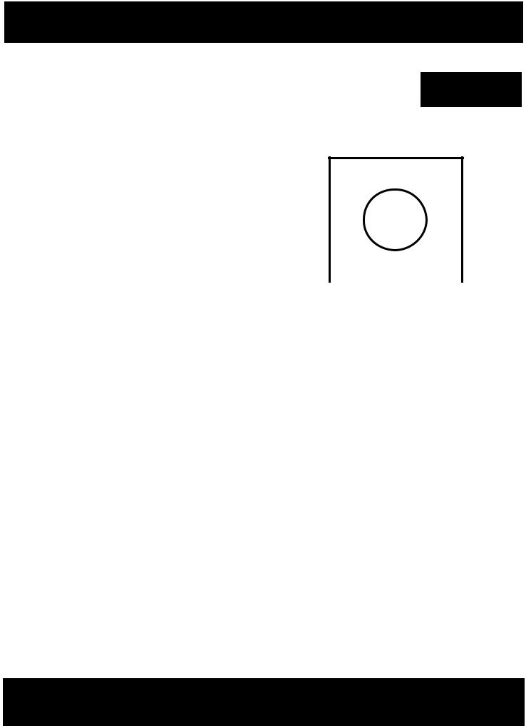
Case Style |
∙Excellent Repeatability (Wafer-to-Wafer and Lot-to-Lot)
∙Small Size
∙Low Loss, High Q
∙Available with Round or Square Bonding Pads
Description |
|
|
|
|
|
|
|
M/A-COM’s MA4M series of MNS (metal-nitride-silicon) sili- |
|
|
|
|
|
|
|
con chip capacitors is designed specifically for high reliability and |
|
|
|
|
|
|
|
repeatable performance in microwave circuit applications. These |
|
|
|
|
|
|
|
capacitors are made using a low pressure chemical vapor deposi- |
|
|
|
|
|
|
|
tion (LPCVD) that results in dense, uniform nitride layers. These |
|
|
|
|
|
|
|
capacitors exhibit higher capacitance per unit area (resulting in |
|
|
|
|
|
|
|
|
|
|
|
|
|
||
smaller chip size) than similar MOS, MIS and ceramic capacitors. |
|
|
|
|
|
|
|
Evaporated gold contacts are used to provide an easily bondable |
|
|
|
|
|
|
|
|
|
|
|
|
|
||
metal pad on the capacitor chip. M/A-COM MNS capacitors have |
|
|
|
|
|
|
|
shown no measurable capacitance change when subjected to the |
|
|
|
|
|
|
|
rated standoff voltage of 150ºC. |
|
350 |
|
|
|
||
|
|
|
|
|
|||
|
|
|
|
|
|
|
|
The MA4M series of chip capacitors is an excellent choice for use |
|
|
|
|
|
|
|
in hybrid microwave circuits up through Ku-band, where low |
|
|
|
|
|
|
|
loss, high reliability, small size and temperature stability are |
|
|
|
|
|
|
|
prime concerns. |
|
|
|
|
|
|
|
These chip capacitors are suited for applications requiring DC |
|
|
|
|
|
|
|
blocks, coupling capacitors, bypass capacitors, capacitive loads |
|
|
|
|
|
|
|
and tuning elements in oscillators, multipliers and filters. |
|
|
|
|
|
|
|
Comparison of M/A-COM MNS Capacitors to Ceramic Chip Capacitors
Characteristics Compared |
MNS |
Ceramic |
Operating Temperature Range |
-55 to +200°C |
-55 to +125°C |
|
|
|
Temperature Coefficient |
180 PPM |
1000 PPM |
|
|
|
Insertion Loss of a 20 pF Capacitor in a 50 Ω line at 15 GHz |
0.1 dB |
0.2 dB |
Chip Size |
|
|
200 pF, 100V |
40 x 40 mils |
70 x 70 mils |
20 pF, 100V |
22 x 22 mils |
50 x 50 mils |
|
|
|
V3.00
M/A-COM Division of AMP Incorporated ■ North America: Tel. (800) 366-2266, Fax (800) 618-8883 ■ Asia/Pacific: Tel.+85 2 2111 8088, Fax +85 2 2111 8087 ■ Europe: Tel. +44 (1344) 869 595, Fax+44 (1344) 300 020
www.macom.com |
AMP and Connecting at a Higher Level are trademarks. |
|
Specifications subject to change without notice. |

MNS Microwave Chip Capacitors |
MA4M Series |
|
|
|
|
Specifications
Chip Capacitors with Round Bonding Pads
|
|
Maximum |
|
Nominal |
|
|
Standoff |
|
Top |
|
Capactance |
Voltage |
|
Contact |
Model |
(pF) 1,2,3,4 |
Rating2,5 |
Chip |
Diameter |
Number |
± 10 % |
(Volts) |
Style |
(mils) |
|
|
|
|
|
MA4M2002 |
2 |
200 |
132 |
3.5 |
|
|
|
|
|
MA4M2005 |
5 |
200 |
132 |
6.0 |
|
|
|
|
|
MA4M1010 |
10 |
100 |
132 |
6.0 |
|
|
|
|
|
MA4M1020 |
20 |
100 |
132 |
9.0 |
|
|
|
|
|
MA4M2020 |
20 |
200 |
132 |
11.5 |
|
|
|
|
|
MA4M1030 |
30 |
100 |
132 |
11.0 |
|
|
|
|
|
MA4M1050 |
50 |
100 |
132 |
14.0 |
|
|
|
|
|
MA4M1080 |
80 |
100 |
199 |
18.0 |
|
|
|
|
|
MA4M1100 |
100 |
100 |
199 |
20.0 |
|
|
|
|
|
MA4M2100 |
100 |
200 |
200 |
26.0 |
|
|
|
|
|
MA4M1200 |
200 |
100 |
200 |
28.0 |
|
|
|
|
|
MA4M1250 |
250 |
100 |
200 |
32.0 |
|
|
|
|
|
MA4M1300 |
300 |
100 |
201 |
35.0 |
|
|
|
|
|
MA4M2300 |
300 |
200 |
263 |
45.0 |
|
|
|
|
|
MA4M1600 |
600 |
100 |
263 |
48.0 |
|
|
|
|
|
Chip Capacitors with Square Bonding Pads
|
|
|
Maximum |
|
|
|
|
Standoff |
|
|
Capactance |
Voltage |
|
|
Model |
(pF) |
1,2,3,4 |
Rating2,5 |
Chip |
|
(Volts) |
|||
Number |
± 10 % |
Style |
||
|
|
|
|
|
MA4M3010 |
10 |
200 |
350 |
|
|
|
|
|
|
MA4M3020 |
20 |
200 |
351 |
|
|
|
|
|
|
MA4M3030 |
30 |
200 |
352 |
|
|
|
|
|
|
MA4M3050 |
50 |
200 |
354 |
|
|
|
|
|
|
MA4M3100 |
100 |
50 |
358 |
|
|
|
|
|
|
MA4M3150 |
150 |
50 |
359 |
|
|
|
|
|
|
Notes:
15% capacitance tolerance is available on request.
2Other capacitance and standoff voltage values are available on request.
3Capacitance is measured at 1 MHz.
4Temperature coefficient of capacitance is nominally 180 PPM/°C.
5Device failure may occur if standoff voltage ratio is exceeded.
Maximum Ratings
Applied Voltage |
Specified standoff voltage |
|
|
Operating Temperature |
-55°C to +200°C |
|
|
Storage Temperature |
-55°C to +200°C |
|
|
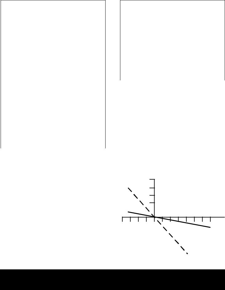
TYPICAL CAPACITANCE CHANGE FOR MNS and CERAMIC CAPACITOR vs TEMPERATURE
(200 pF CAPACITOR)
+10
%
+8 CAPACITANCE CHANGE
+6
+4
TEMPERATURE qC
-75 |
-25 |
0 |
|
25 |
50 |
125 |
|
|
150 |
|
200 |
|||
|
|
-4 |
|
|
|
|
|
|
|
|
|
|
|
|
|
|
|
|
|
|
|
|
|
|
|
||||
|
|
|
|
|
|
|
|
|
M/A-COM MA4M1200 |
|||||
|
|
|
|
|
|
|||||||||
|
|
|
|
|
|
|
|
|
|
CAPACITOR |
|
|
||
|
|
-6 |
|
|
|
|
|
|
|
|
|
|
|
|
|
|
|
|
|
|
|
|
|
|
|
|
|
|
|
|
|
-8 |
|
|
|
|
|
|
|
|
|
|
|
|
|
|
|
|
|
|
|
|
|
|
|
|
|
|
|
|
|
|
|
|
|
|
|
|
|
|
|
|
|
|
|
|
-10 |
|
|
|
|
|
|
|
|
|
|
||
|
|
|
|
|
|
|
|
|
CERAMIC |
|
|
|||
|
|
|
|
|
|
|
|
|||||||
|
|
|
|
|
|
|
|
|
|
CAPACITOR |
|
|
||
|
|
|
|
|
|
|
|
|
|
|
|
|
|
|
V3.00
M/A-COM Division of AMP Incorporated ■ North America: Tel. (800) 366-2266, Fax (800) 618-8883 ■ Asia/Pacific: Tel.+85 2 2111 8088, Fax +85 2 2111 8087 ■ Europe: Tel. +44 (1344) 869 595, Fax+44 (1344) 300 020
www.macom.com |
AMP and Connecting at a Higher Level are trademarks. |
|
Specifications subject to change without notice. |
 Loading...