

Mackie MS1202VLZ User Manual
MICROSERIES1202-VLZ
MIC
/
LINE MIXER
OWNER’S MANUAL
TM
CAUTION
RISK OF ELECTRIC SHOCK
DO NOT OPEN
REPLACE WITH THE SAME TYPE FUSE AND RATING.
DISCONNECT SUPPLY CORD BEFORE CHANGING FUSE
LEFT
CONTROL
ROOM
BAL/UNBAL BAL/UNBAL
L
R
+4
MIC
MAIN
OUTPUT
LEVEL
CONCEIVED, DESIGNED, AND MANUFACTURED BY MACKIE DESIGNS INC.
120 VAC 50/60 Hz 20W
315mA/250V SLO-BLO
CAUTION:
TO REDUCE THE RISK OF
FIRE REPLACE WITH SAME
TYPE FUSE AND RATING
POWER
ON
ON
MICRO SERIES
1202-VLZ
LOW NOISE HIGH HEADROOM
12-CHANNEL MIC/LINE MIXER
RIGHT
PHANTOM
WARNING:
TO REDUCE THE RISK OF FIRE OR ELECTRIC SHOCK, DO NOT
EXPOSE THIS EQUIPMENT TO RAIN OR MOISTURE. DO NOT REMOVE COVER.
NO USER SERVICEABLE PARTS INSIDE. REFER SERVICING TO QUALIFIED PERSONNEL.
AVIS :
RISCQUE DE CHOC ÉLECTRIQUE — NE PAS OUVRIR
UTILISE UN FUSIBLE DE RECHANGE DE MÊME TYPE.
DEBRANCHER AVANT DE REMPLACER LE FUSIBLE
ALT
R
OUTPUT
4
L
SERIAL NUMBER
(
PRE-FADER / PRE EQ TIP SEND / RING RETURN
CHANNEL INSERTS
2
3
WOODINVILLE WASHINGTON
MANUFACTURING DATE
)
1
MADE IN USA
MIC
LINE IN 1
U
10
+10dB
U
OO
U
OO
U
-15
U
U
LR
1
MUTE
ALT 3-4
PRE FADER
SOLO
M
TRIM
+15
+15
+15
+12-12
+15-15
OO
GAIN
1
MIC
2
MIC
3
BAL
BAL
BAL
OR
UNBAL
UNBAL
LINE IN 2
LOW CUT
LOW CUT
18dB/OCT
-
1
0
G
A
C
I
I
N
60
-40dB
U
+20dB
75 Hz
75 Hz
18dB/OCT
-
1
0
G
A
C
I
I
N
M
U
60
10
-40dB
+10dB
TRIM
U
AUX
AUX
1
MON/
MON/
EFX
OO
+15
U
2
EFX
OO
+15
U
EQ
HI
12kHz
12kHz
+15-15
U
MID
2.5kHz
2.5kHz
+12-12
U
LOW
LOW
80Hz
80Hz
+15-15
PAN
PAN
LR
2
MUTE
ALT 3-4
PRE FADER
SOLO
U
OO
+20dB
GAIN
OR
OR
UNBAL
LINE IN 3
LOW CUT
75 Hz
18dB/OCT
-
1
0
G
A
C
I
I
N
M
U
60
10
-40dB
+10dB
TRIM
U
AUX
1
1
MON/
EFX
EFX
OO
+15
U
2
2
EFX
EFX
OO
+15
U
EQ
EQ
MID
HI
HI
12kHz
+15-15
U
MID
2.5kHz
+12-12
U
LOW
80Hz
+15
-15
PAN
LR
3
MUTE
ALT 3-4
PRE FADER
SOLO
U
OO
+20dB
GAIN
MIC
LINE IN 4
U
10
+10dB -40dB
U
OO
U
OO
U
U
U
LR
4
MUTE
ALT 3-4
PRE FADER
SOLO
M
TRIM
+15
+15
+15-15
+12-12
+15-15
OO
GAIN
G
C
I
U
A
+20dB
4
UNBAL
LOW CUT
75 Hz
18dB/OCT
-
1
0
I
N
60
BAL
OR
AUX
1
MON/
EFX
2
EFX
EQ
HI
12kHz
MID
2.5kHz
LOW
80Hz
PAN
LEFT/
1
LEFT
RIGHT
2
STEREO AUX RETURNS
MONO
L
BAL
OR
UNBAL
R
LINE IN 5-6
U
AUX
1
MON/
EFX
OO
+15
U
2
EFX
OO
+15
U
EQ
HI
12kHz
+15-15
U
MID
2.5kHz
+12
-12
U
LOW
80Hz
+15-15
PAN
LR
5 6
MUTE
ALT 3-4
PRE FADER
SOLO
U
OO
+20dB
GAIN
LINE IN 7-8
OO
OO
-15
LR
7 8
MUTE
ALT 3-4
PRE FADER
SOLO
AUX SEND
U
+15
U
+15
U
+15-15
U
+12-12
U
+15
U
OO
GAIN
1
L
2
R
TAPE
INPUT
MONO
L
BAL
OR
UNBAL
R
LINE IN 9-10
U
AUX
1
MON/
EFX
OO
+15
U
2
EFX
OO
+15
U
EQ
HI
12kHz
+15-15
U
MID
2.5kHz
+12
-12
U
LOW
80Hz
+15-15
PAN
LR
9 10
MUTE
ALT 3-4
PRE FADER
SOLO
OO
+20dB
GAIN
ALL BAL/UNBAL
RIGHT
MONO
BAL/UNBAL
L
MICRO SERIES 1202-VLZ
12-CHANNEL MIC/LINE MIXER
R
TAPE
OUTPUT
MAIN OUTS
MONO
MONO
L
L
BAL
BAL
OR
OR
UNBAL
UNBAL
AUX
1
MON/
EFX
2
EFX
EQ
HI
12kHz
MID
2.5kHz
LOW
80Hz
PAN
U
+20dB
R
LINE IN 11-12
U
OO
+15
U
OO
+15
U
+15-15
U
+12-12
U
+15
-15
LR
11 1 2
MUTE
ALT 3-4
PRE FADER
SOLO
U
OO
GAIN
R
PHONES
AUX
MON/
12kHz
2.5kHz
LOW
PAN
+20dB
U
1
EFX
OO
+10
AUX 1 MASTER
MON/PRE
2
POST
EFX
AUX 1
SELECT
EQ
HI
MID
80Hz
SOURCE
POWER
MAIN
ALT 3-4
TAPE
ASSIGN
TO MAIN MIX
U
OO
MAX
CONTROL
/ PHONES
ROOM
U
1
OO
+20
NORMALLED
U
2
U
BAL
OO
LEFT
0dB=0dBu
+28
+10
+7
+4
+2
0
-2
-4
-7
-10
-20
-30
RUDE
SOLO
LIGHT
U
OO
MAIN MIX
+20
RIGHT
+10dB
AUX
RETURN
CLIP
LEVEL SET
EFX TO
MONITOR
MIX
CAUTION AVIS
RISK OF ELECTRIC
DO NOT OPEN
RISQUE DE
CAUTION: TO REDUCE THE RISK OF ELECTRIC SHOCK
DO NOT REMOVE COVER (OR BACK)
NO USER-SERVICEABLE PARTS INSIDE
REFER SERVICING TO QUALIFIED PERSONNEL
ATTENTION: POUR EVITER LES RISQUES DE CHOC
ELECTRIQUE, NE PAS ENLEVER LE COUVERCLE. AUCUN
ENTRETIEN DE PIECES INTERIEURES PAR L'USAGER. CONFIER
L'ENTRETIEN AU PERSONNEL QUALIFIE.
AVIS: POUR EVITER LES RISQUES D'INCENDIE OU
D'ELECTROCUTION, N'EXPOSEZ PAS CET ARTICLE
The lightning flash with arrowhead symbol within an equilateral
triangle is intended to alert the user to the presence of uninsulated
"dangerous voltage" within the product's enclosure, that may be
of sufficient magnitude to constitute a risk of electric shock to persons.
Le symbole éclair avec point de flèche à l'intérieur d'un triangle
équilatéral est utilisé pour alerter l'utilisateur de la présence à
l'intérieur du coffret de "voltage dangereux" non isolé d'ampleur
suffisante pour constituer un risque d'éléctrocution.
The exclamation point within an equilateral triangle is intended to
alert the user of the presence of important operating and maintenance
(servicing) instructions in the literature accompanying the appliance.
Le point d'exclamation à l'intérieur d'un triangle équilatéral est
employé pour alerter les utilisateurs de la présence d'instructions
importantes pour le fonctionnement et l'entretien (service) dans le
livret d'instruction accompagnant l'appareil.
CHOC
NE PAS OUVRIR
A LA PLUIE OU A L'HUMIDITE
SHOCK
ELECTRIQUE
SAFETY INSTRUCTIONS
1. Read Instructions — All the safety and operation
instructions should be read before this Mackie product is
operated.
2. Retain Instructions — The safety and operating instructions should be kept for future reference.
3. Heed Warnings — All warnings on this Mackie product and
in these operating instructions should be followed.
4. Follow Instructions — All operating and other instructions
should be followed.
5. Water and Moisture — This Mackie product should not be
used near water – for example, near a bathtub, washbowl,
kitchen sink, laundry tub, in a wet basement, near a
swimming pool, swamp or salivating St. Bernard dog, etc.
6. Heat — This Mackie product should be situated away
from heat sources such as radiators, or other devices which
produce heat.
7. Power Sources — This Mackie product should be
connected to a power supply only of the type described in
these operation instructions or as marked on this Mackie
product.
8. Power Cord Protection — Power supply cords should be
routed so that they are not likely to be walked upon or
pinched by items placed upon or against them, paying
particular attention to cords at plugs, convenience receptacles,
and the point where they exit this Mackie product.
9. Object and Liquid Entry — Care should be taken so that
objects do not fall into and liquids are not spilled into the
inside of this Mackie product.
10 . Damage Requiring Service — This Mackie product should
be serviced only by qualified service personnel when:
A. The power-supply cord or the plug has been
damaged; or
B. Objects have fallen, or liquid has spilled into
this Mackie product; or
C. This Mackie product has been exposed to rain;
or
D. This Mackie product does not appear to operate
normally or exhibits a marked change in
performance; or
E. This Mackie product has been dropped, or its
chassis damaged.
11 . Servicing — The user should not attempt to service this
Mackie product beyond those means described in this
operating manual. All other servicing should be referred to the
Mackie Service Department.
12 . To prevent electric shock, do not use this polarized plug
with an extension cord, receptacle or other outlet unless the
blades can be fully inserted to prevent blade exposure.
Pour préevenir les chocs électriques ne pas utiliser cette fiche
polariseé avec un prolongateur, un prise de courant ou une autre
sortie de courant, sauf si les lames peuvent être insérées à fond
sans laisser aucune pariie à découvert.
13 . Grounding or Polarization — Precautions should be taken
so that the grounding or polarization means of this Mackie
product is not defeated.
14 . This apparatus does not exceed the Class A/Class B
(whichever is applicable) limits for radio noise emissions from
digital apparatus as set out in the radio interference
regulations of the Canadian Department of Communications.
ATTENTION —Le présent appareil numérique n’émet pas de
bruits radioélectriques dépassant las limites applicables aux
appareils numériques de class A/de class B (selon le cas)
prescrites dans le règlement sur le brouillage radioélectrique
édicté par les ministere des communications du Canada.
15 . To prevent hazard or damage, ensure that only
microphone cables and microphones designed to IEC 268-15A
are connected.
WARNING — To reduce the risk of fire or electric shock, do
not expose this appliance to rain or moisture.

READ THIS PAGE!!!
We realize that you must be dying to try out
your new MicroSeries 1202-VLZ. Or you might be
one of those people who never read manuals.
Either way, all we ask is that you read this page
NOW, and the rest can wait until you’re good and
ready. But do read it — you’ll be glad you did.
LEVEL-SETTING PROCEDURE
Message to seasoned pros: do not set
levels using the old “Turn the trim up until
the clip light comes on, then back off a
hair” trick. When a Mackie Designs mixer
clip light comes on, you really are about to
clip. We worked and slaved to come up
with a better system, one that provides low
noise and high headroom.
Adjusting input levels (Chs. 1–4 only)
On the first four channels, it’s not even
necessary to hear what you’re doing to set
optimal levels. But if you’d like to: Plug
headphones into the
set the
CONTROL ROOM/PHONES
about one-quarter of the way up.
The following steps must be performed
one channel at a time:
1. Turn the
knobs fully down (counterclockwise).
2. Set the
3. Connect the signal source to the input.
4. Engage (push in) the
5. Play something into the selected input.
6. Adjust the channel’s
7. If you’d like to apply some
8. Disengage that channel’s
9. Repeat for each of channels
EQ
This could be an instrument, a singing
or speaking voice, or a line input such
as a CD player or tape recorder output.
Be sure that the volume of the input is
the same as it would be during normal
use. If it isn’t, you might have to
readjust these levels during the middle
of the set.
that the display on the right LED
meter stays around “
higher than “
and return to step 6.
through 4.
PHONES
TRIM, GAIN
knobs at the center detent.
+7
.”
jack, then
and
AUX
SOLO
switch.
TRIM
control so
0
” and never goes
EQ
, do so now
SOLO
switch.
1
knob
send
Other Nuggets of Wisdom
For optimum sonic performance, the channel
GAIN
knobs and the
set near the “
Always turn the
ROOM/PHONES
making connections to and from your
MS1202-VLZ.
If you shut down your equipment, turn off
your amplifier(s) first. When powering up, turn
on your amplifier(s) last.
Save the shipping box! You may need it
someday, and you don’t want to have to pay for
another one.
MAIN MIX
U
” (unity gain) markings.
MAIN MIX
level controls down before
knob should be
and
CONTROL
INSTANT MIXING
Here’s how to get going
right away, assuming you own a
microphone and a keyboard:
1. Plug your microphone into channel
input.
2. Turn on the MS1202-VLZ.
3. Perform the Level-Setting Procedure
4. Connect cords from the
RCA, your choice) to your amplifier.
5. Hook up speakers to the amp and turn it on.
6. Turn up the MS1202-VLZ’s channel
knob to the center detent and the
knob one quarter of the way up.
7. Sing like a canary!
8. Plug your keyboard into stereo channel
9. Turn that channel’s
detent.
10. Play like a madman and sing like a canary!
It’s your first mix!
MAIN OUTS
GAIN
knob to the center
1
’s
MIC
.
(XLR, 1⁄4" or
1 GAIN
MAIN MIX
5-6
.
Please write your serial number here for
future reference (i.e. insurance claims,
tech support, return authorization, etc.):
Purchased at:
Date of Purchase:
Part No. 820-028-00 Rev. C 3/97
©1997 Mackie Designs Inc., All Rights Reserved. Printed in the U.S.A.
3
INTRODUCTION
Thank you! There are a lot of makes and
models of compact mixers out there, all competing for your bucks… but you have voted
with your wallet for the folks in Woodinville
who specialize in American-made mixers.
Now that you have your MicroSeries
1202-VLZ, find out how to get the most from it.
That’s where this manual comes in.
HOW TO USE THIS MANUAL
Since many of you folks will want to hook up
your MS1202-VLZ immediately, the first pages
you will encounter after the table of contents
are the ever popular hookup diagrams. These
show typical mixer setups for Record/Mixdown,
Video, Disc Jockey and Stereo PA. After this
section is a detailed tour of the entire mixer.
Every feature of the MS1202-VLZ is described
“geographically;” in other words, in order of where
it is physically placed on the mixer’s top or rear
panel. These descriptions are divided into the
first three manual chapters, just as your mixer is
organized into three distinct zones:
1. PATCHBAY: The patchbay along the top
and back.
2. CHANNEL STRIP: The eight channel
strips on the left.
3. OUTPUT SECTION: The output section on
the right.
Throughout these chapters you’ll find illustrations, with each feature numbered. If you’re
curious about a feature, simply locate it on the
appropriate illustration, notice the number
attached to it, and find that number in the
nearby paragraphs.
MIC 1
MIC 2
BAL
BAL
OR
OR
UNBAL
UNBAL
LINE IN 2
LINE IN 1
PRE FADER
LOW CUT
LOW CUT
75 Hz
75 Hz
18dB/OCT
18dB/OCT
-
-
1
1
0
0
G
G
A
A
C
C
I
I
I
I
N
N
M
M
U
U
60
10
60
10
-40dB
+10dB
-40dB
+10dB
TRIM
TRIM
U
U
AUX
AUX
1
1
MON/
MON/
EFX
EFX
OO
OO
+15
+15
U
U
2
2
EFX
EFX
OO
OO
+15
+15
U
U
EQ
EQ
HI
HI
12kHz
12kHz
+15-15
+15
-15
U
U
MID
MID
2.5kHz
2.5kHz
+12-12
+12
-12
U
U
LOW
LOW
CHANNEL STRIPS
80Hz
80Hz
+15-15
+15-15
PAN
PAN
LR
LR
2
1
MUTE
MUTE
ALT 3-4
ALT 3-4
PRE FADER
SOLO
SOLO
U
U
OO
OO
+20dB
+20dB
GAIN
GAIN
MIC 4
MIC 3
BAL
OR
UNBAL
LINE IN 4
LINE IN 3
PATCHBAY
LOW CUT
75 Hz
18dB/OCT
-
1
0
G
A
C
I
I
N
M
M
U
U
60
10
10
-40dB
+10dB
+10dB
TRIM
TRIM
U
U
AUX
1
MON/
EFX
OO
OO
+15
U
U
2
EFX
OO
OO
+15
U
U
EQ
HI
12kHz
+15-15
U
U
MID
2.5kHz
+12-12
+12-12
U
U
LOW
80Hz
+15-15
PAN
LR
LR
4
3
MUTE
MUTE
ALT 3-4
ALT 3-4
PRE FADER
PRE FADER
SOLO
SOLO
U
OO
OO
+20dB
GAIN
GAIN
G
C
I
+15
+15
+15-15
+15-15
U
+20dB
BAL
OR
UNBAL
LOW CUT
75 Hz
18dB/OCT
-
1
0
A
I
N
60
-40dB
AUX
1
MON/
EFX
2
EFX
EQ
HI
12kHz
MID
2.5kHz
LOW
80Hz
PAN
RIGHT
MONO
LEFT/
1
LEFT
RIGHT
2
STEREO AUX RETURNS
MONO
L
BAL
OR
UNBAL
R
LINE IN 5-6
U
AUX
1
MON/
EFX
OO
+15
U
2
EFX
OO
+15
U
EQ
HI
12kHz
+15-15
U
MID
2.5kHz
+12-12
U
LOW
80Hz
+15-15
PAN
LR
5 6
MUTE
ALT 3-4
PRE FADER
SOLO
U
OO
+20dB
GAIN
PRE FADER
LINE IN 7-8
OO
OO
-15
LR
7 8
MUTE
ALT 3-4
SOLO
ALL BAL/UNBAL
AUX SEND
U
+15
U
+15
U
+15
U
+12-12
U
+15-15
OO
GAIN
1
L
2
R
MONOLMONO
L
BAL
OR
UNBAL
R
AUX
1
MON/
EFX
2
EFX
EQ
HI
12kHz
MID
2.5kHz
-12
LOW
80Hz
PAN
9 10
PRE FADER
U
+20dB
TAPE
INPUT
LINE IN 9-10
U
OO
U
OO
U
U
U
-15
LR
MUTE
ALT 3-4
SOLO
GAIN
You’ll also find cross-references to these
numbered features within a paragraph. For instance, if you see “To wire your own cables:
,” simply find that number in the manual
and you’ve found your answer.
Finally, you’ll notice feature numbers like
this:
. These numbers direct you to relevant
information.
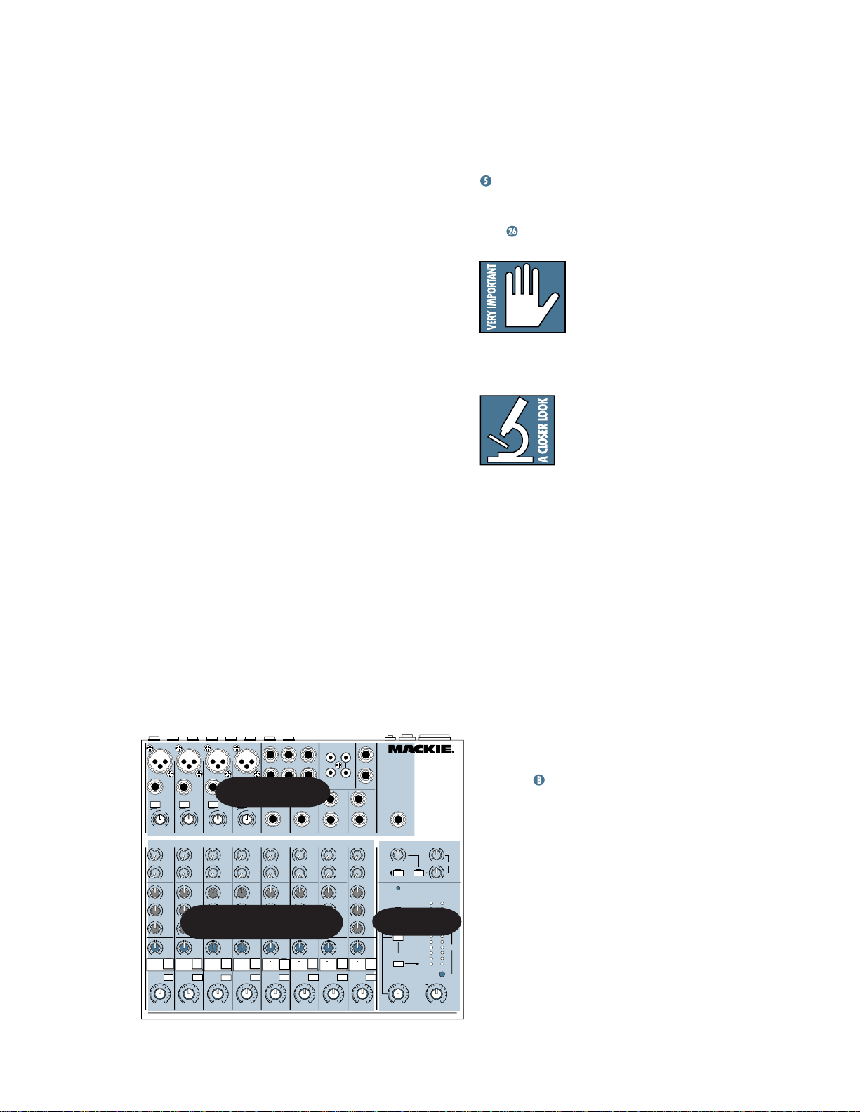
This icon marks information that is critically
important or unique to the
MS1202-VLZ. For your own
good, read them and remem-
ber them. They will be on the final test. And
the final test score will go down on your
Permanent Record.
This icon will lead you to
in-depth explanations of
features and practical tips.
While not mandatory, they
usually have some valuable
nugget of information.
THE GLOSSARY: A HAVEN OF
NON-TECHINESS FOR THE NEOPHYTE
Since the MS1202-VLZ is often purchased by
folks who are new to the jargon of professional
audio, we’ve included a fairly comprehensive
dictionary of pro-audio terms. If terms like “clipping,” “noise floor,” or “unbalanced” leave you
blank, flip to the glossary at the back of this
manual for a quick explanation.
A PLUG FOR THE CONNECTORS SECTION
Also at the back of this manual is a section
on connectors: XLR connectors, balanced con-
BAL/UNBAL
L
MICRO SERIES 1202-VLZ
12-CHANNEL MIC/LINE MIXER
R
TAPE
MAIN OUTS
OUTPUT
MONO
L
BAL
BAL
OR
OR
UNBAL
UNBAL
R
R
AUX
1
MON/
EFX
+15
2
EFX
+15
EQ
HI
12kHz
+15-15
MID
2.5kHz
+12
LOW
80Hz
+15
PAN
U
OO
+20dB
LINE IN 11-12
U
OO
U
OO
U
-15
U
-12
U
LR
11 12
MUTE
ALT 3-4
PRE FADER
SOLO
PHONES
U
OO
+10
AUX 1
EFX TO
SELECT
MONITOR
POWER
MAIN
MIX
OUTPUT
ALT 3-4
SECTION
TAPE
U
U
BAL
OO
MAX
/ PHONES
OO
OO
LEFT
0dB=0dBu
RUDE
SOLO
LIGHT
OO
MAIN MIX
U
U
+28
+10
+7
+4
+2
0
-2
-4
-7
-10
-20
-30
U
AUX
1
MON/
EFX
+15
AUX 1 MASTER
MON/PRE
2
POST
EFX
+15
EQ
HI
12kHz
+15
SOURCE
MID
2.5kHz
+12
LOW
80Hz
+15-15
PAN
ASSIGN
TO MAIN MIX
U
OO
+20dB
CONTROL
GAIN
ROOM
nectors, unbalanced connectors, special hybrid
connectors. Although we provide diagrams
throughout the manual, the Connections
appendix
gives more of the whys and
wherefores for beginners.
ARCANE MYSTERIES ILLUMINATED
1
+20
NORMALLED
2
AUX
+20
RETURN
RIGHT
CLIP
LEVEL SET
+10dB
Finally, we’ve included an appendix entitled
“Balanced Lines, Phantom Powering, Grounding
and Other Arcane Mysteries.” This section
discusses some of the down ’n’ dirty practical
realities of microphones, fixed installations,
grounding, and balanced versus unbalanced
lines. It’s a gold mine for the neophyte and even
the seasoned pro might learn a thing or two.
4

CONTENTS
LEVEL-SETTING PROCEDURE ..................................... 3
HOOKUP DIAGRAMS .............................................. 6
PATCHBAY DESCRIPTION ...................................... 10
MIC INPUTS ................................................... 10
PHANTOM POWER ........................................ 10
LINE INPUTS .................................................. 10
LOW CUT* ..................................................... 11
TRIM* ........................................................... 11
STEREO LINE INPUTS* .................................... 12
EFFECTS: SERIAL OR PARALLEL? ..................... 12
INSERT........................................................... 13
AUX RETURNS* ............................................. 13
TAPE IN.......................................................... 14
XLR MAIN OUTS* .......................................... 14
XLR MAIN OUTPUT LEVEL SWITCH* ............... 15
1
⁄4" MAIN OUTS ............................................. 15
TAPE OUTPUT ................................................ 15
PHONES......................................................... 16
ALT 3-4.......................................................... 16
CONTROL ROOM*.......................................... 16
AUX SEND 1 & 2 ............................................ 16
POWER CONNECTION .................................... 17
FUSE .............................................................. 17
POWER SWITCH ............................................ 17
PHANTOM SWITCH ........................................ 17
CHANNEL STRIP DESCRIPTION .............................. 18
“U” LIKE UNITY GAIN .................................... 18
GAIN ............................................................. 18
PRE-FADER SOLO* ......................................... 18
MUTE/ALT 3-4*............................................. 18
PAN ............................................................... 19
CONSTANT LOUDNESS ! ! !.............................. 19
3-BAND EQ* .................................................. 19
AUX SEND ..................................................... 20
OUTPUT SECTION DESCRIPTION ............................ 21
MAIN MIX ..................................................... 21
VLZ MIX ARCHITECTURE* .............................. 21
SOURCE MATRIX*.......................................... 21
CONTROL ROOM / PHONES .......................... 22
PRE-FADER SOLO (PFL) .................................. 22
RUDE SOLO LIGHT* ........................................ 23
ASSIGN TO MAIN MIX* ................................. 23
METERS ......................................................... 23
AUX TALK ...................................................... 24
AUX 1 PRE/POST SELECT ............................... 24
AUX 1 MASTER .............................................. 24
AUX RETURNS ............................................... 25
EFX TO MONITOR* ........................................ 25
JACK NORMALLING ....................................... 25
MODIFICATIONS ................................................... 26
BLOCK DIAGRAM.................................................. 29
GAIN STRUCTURE DIAGRAM ................................. 30
SPECIFICATIONS.................................................... 31
SERVICE INFO ....................................................... 32
APPENDIX: Glossary of Pro Audio Terms................ 33
APPENDIX: Connections ......................................... 42
APPENDIX: Balanced Lines, Phantom Powering,
Grounding and Other Arcane Mysteries ......................... 45
*NEW! IMPROVED!
PROFESSIONAL FEATURES!
For those of you accustomed to the original MS1202, do not be daunted by all the
new or improved features — we added them
just for you! Details of these features are
wedged into the manual with all the other
great stuff.
5
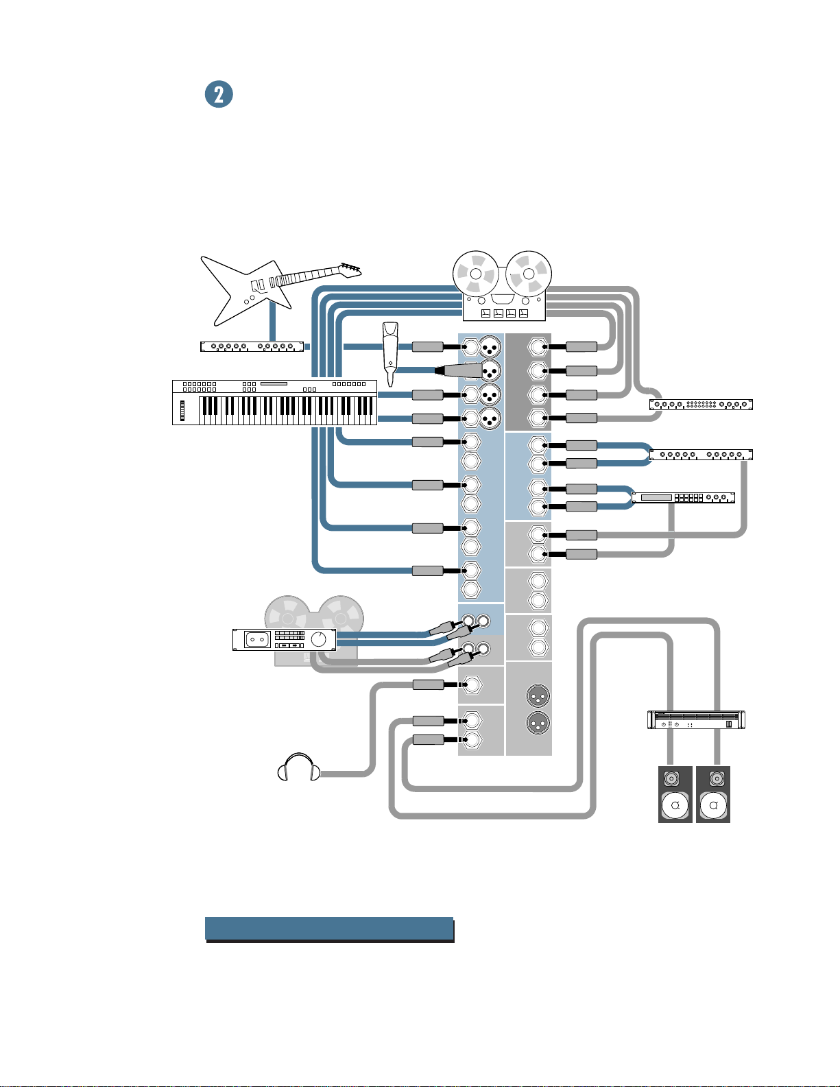
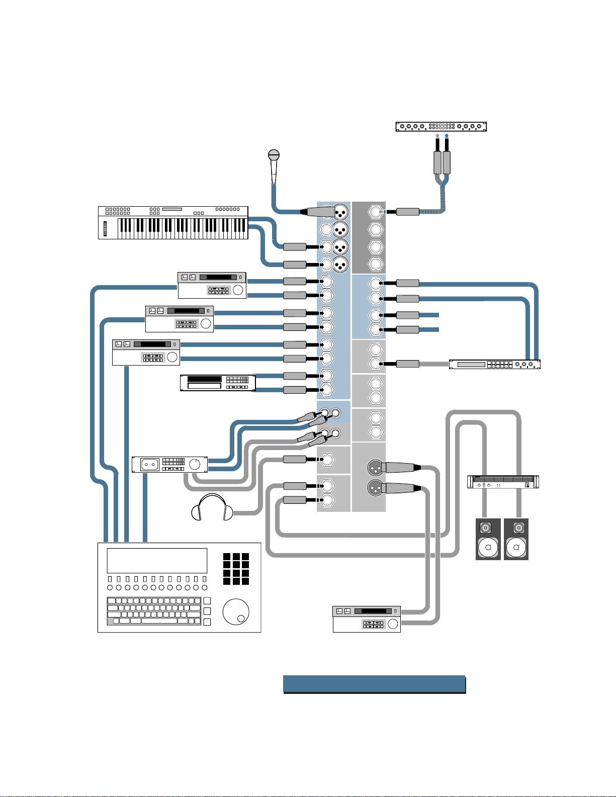
HOOKUP DIAGRAMS
Guitar Effects
Keyboard or other line-level input
2-track Mixdown Deck2-track Mixdown Deck2-track Mixdown Deck
(record)
4-track Recorder
in (record)out (play)
IMPORTANT:
ALL Channel Insert
plugs are inserted
to the SECOND click.
1
2
3
4
L
5
MONO
R
6
L
7
MONO
R
8
L
9
MONO
R
10
L
11
MONO
R
12
out
(play)
R
L
L
R
in
OUT
CNTRL ROOM
OUTPUTS
CHANNEL INSERTSAUX RETURNS
CHANNEL
1
INPUTS
2
OUT
AUX
OUT
ALT 3/4
IN-TAPE-OUT
OUT
MAIN
PHONES
OUT
MAIN
1
2
out
3
4
L
R
Mono Processor
in
out
Mono in / stereo out
Reverb
in
L
R
out
in
Digital Delay
1
2
L
R
L
R
Power
Amplifier
FULL SYMMETRY DUAL DIFFERENTIAL HIGH CURRENT DESIGN
CH
CH
1
2
MS1202-VLZ 4-Tk Record/2-Tk Mix
6
Studio Monitors
Keyboard or other
line-level input
V/O Mic
Compressor
out
in
1
1
1
Video Deck #3
SMPTE Control
Time Code DAT
Video Deck #2
L
R
L
R
Video Deck #1
L
Audio out
R
Audio out
CD Player
L
out
R
in
L
Audio out
R
L
R
2
3
4
5
6
7
8
9
10
11
12
L
L
L
MONO
R
L
MONO
R
L
MONO
R
L
MONO
R
R
R
OUT
OUTPUTS
CHANNEL INSERTSAUX RETURNS
CHANNEL
1
INPUTS
2
OUT
AUX
OUT
ALT 3/4
IN-TAPE-OUT
OUT
MAIN
PHONES
CNTRL ROOM
OUT
MAIN
2
3
4
L
R
L
R
1
2
*Note: Aux Return #2
can be used as an
extra stereo input
Multi Effect Processor
out
in
L
R
L
R
Power
Amplifier
FULL SYMMETRY DUAL DIFFERENTIAL HIGH CURRENT DESIGN
CH
CH
1
2
Mackie Designs: Video Setup
scene #1 _ 23:94:10
Time Base
Multi - VCR Video Switcher
with time code interface
(optional)
Master Video Deck
MS1202-VLZ Video Setup
Studio Monitors
7
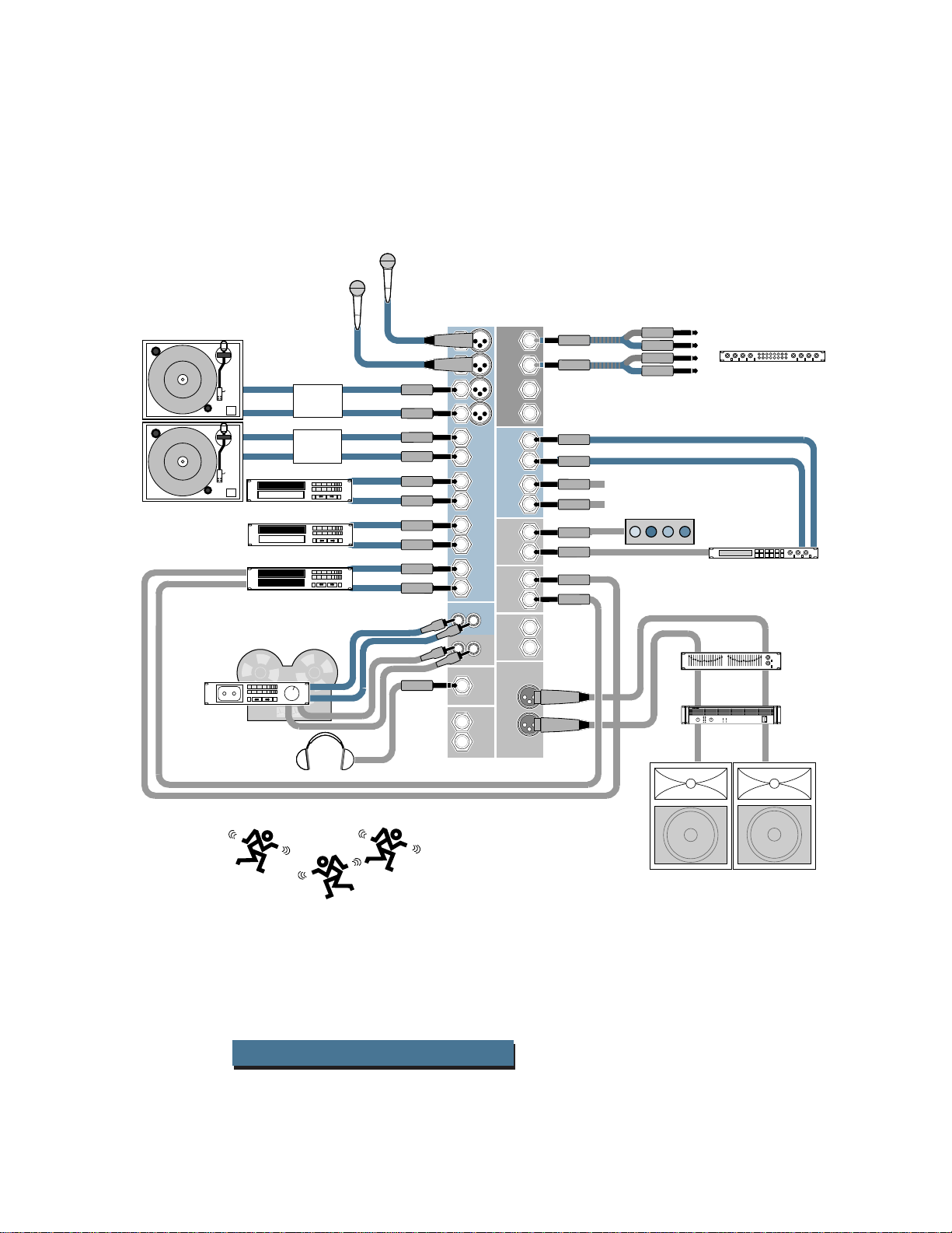
MORE HOOKUP DIAGRAMS
Turntable
in
2-Track
Deck
CD Player
CD Player
Sampler
L
R
(record)
1
1
10
11
12
L
L
3
4
5
6
7
8
9
L
MONO
R
L
MONO
R
L
MONO
R
L
MONO
R
R
R
OUT
OUTPUTS
2
Phono
Preamps
RIAA
RIAA
L
out
R
L
out
R
out
out
(play)
in
CHANNEL INSERTSAUX RETURNS
CHANNEL
1
INPUTS
2
OUT
AUX
OUT
ALT 3/4
IN-TAPE-OUT
OUT
MAIN
PHONES
CNTRL ROOM
OUT
MAIN
1
2
3
4
L
R
L
R
1
2
L
R
L
R
Note: Aux Return #2 can
be used as an extra stereo input
Triggered Lights
org
in
out
in
out
Stereo EQ
FULL SYMMETRY DUAL DIFFERENTIAL HIGH CURRENT DESIGN
CH
1
Amplifier
CH
2
Stereo Compressor
Multi Effect
Processor
Power
Left PA Speaker
Right PA Speaker
People Dancing
MS1202-VLZ DJ Setup
8
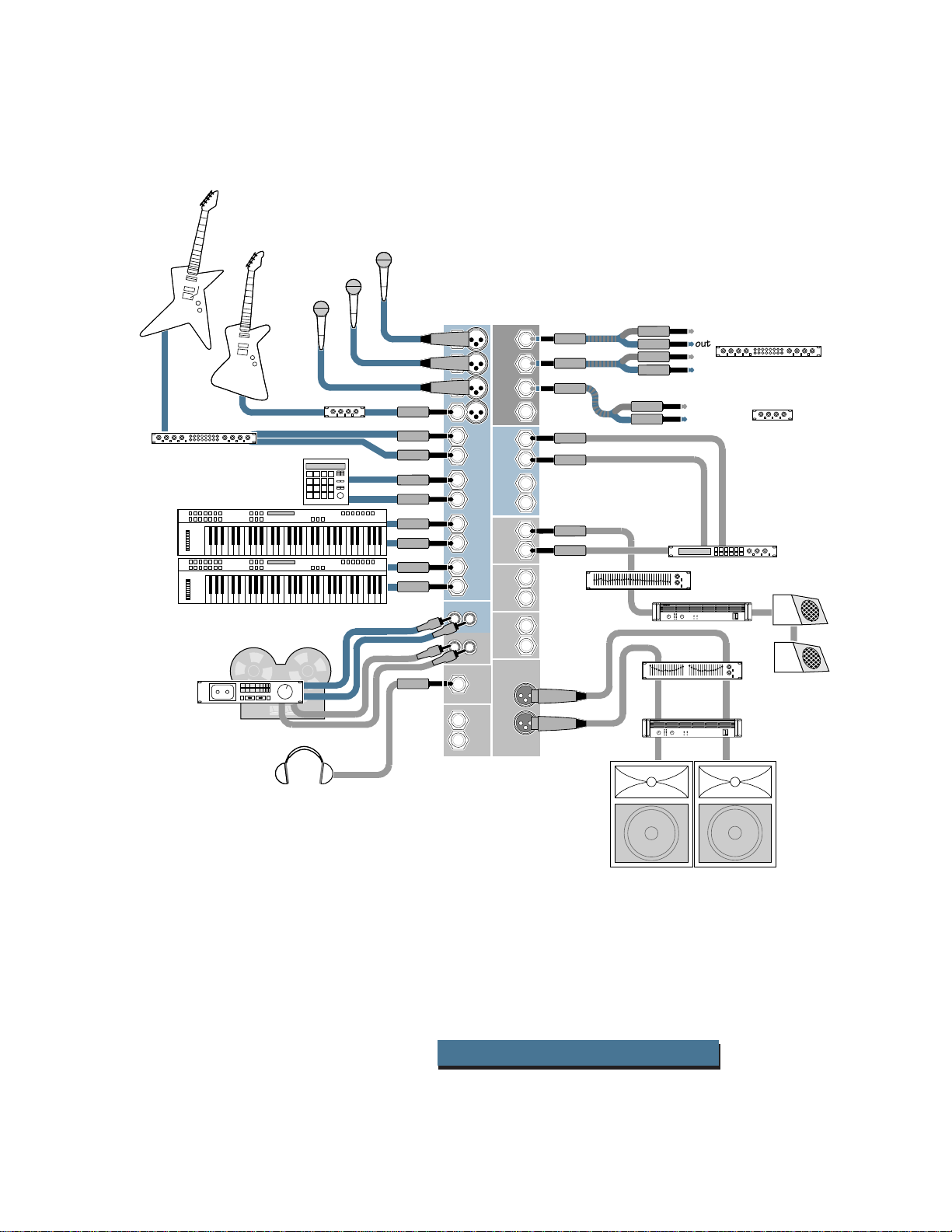
Vocal Mics
Stereo Guitar Effects
Keyboard or other
line level input
2-Track
Deck
(record)
Line out
from
Bass Amp
Drum
Machine
in
Bass Effects
org
org
out
(play)
1
3
4
5
6
7
8
9
10
11
12
L
L
1
2
3
L
MONO
R
L
MONO
R
L
MONO
R
L
MONO
R
R
R
OUT
OUTPUTS
CHANNEL INSERTSAUX RETURNS
CHANNEL
1
INPUTS
2
OUT
AUX
OUT
ALT 3/4
IN-TAPE-OUT
OUT
MAIN
PHONES
CNTRL ROOM
OUT
MAIN
in
1
2
out
in
out
Stereo Compressor
3
4
in
out
Mono Compressor
L
R
L
R
1
2
L
R
Mono EQ
CH
1
FULL SYMMETRY DUAL DIFFERENTIAL HIGH CURRENT DESIGN
CH
2
Multi Effect
Processor
Power Amp
Stage Monitors
L
R
red
red
Stereo EQ
FULL SYMMETRY DUAL DIFFERENTIAL HIGH CURRENT DESIGN
CH
1
Power
Amplifier
CH
2
This setup can be easily reconfigured to become
a Mono PA setup.
A. Stereo sources should feed the left mono
side of channel input only.
B. Pan each channel hard left.
C. Connect Mono PA system to
Left main output.
Left PA Speaker
MS1202-VLZ Stereo PA
Right PA Speaker
9
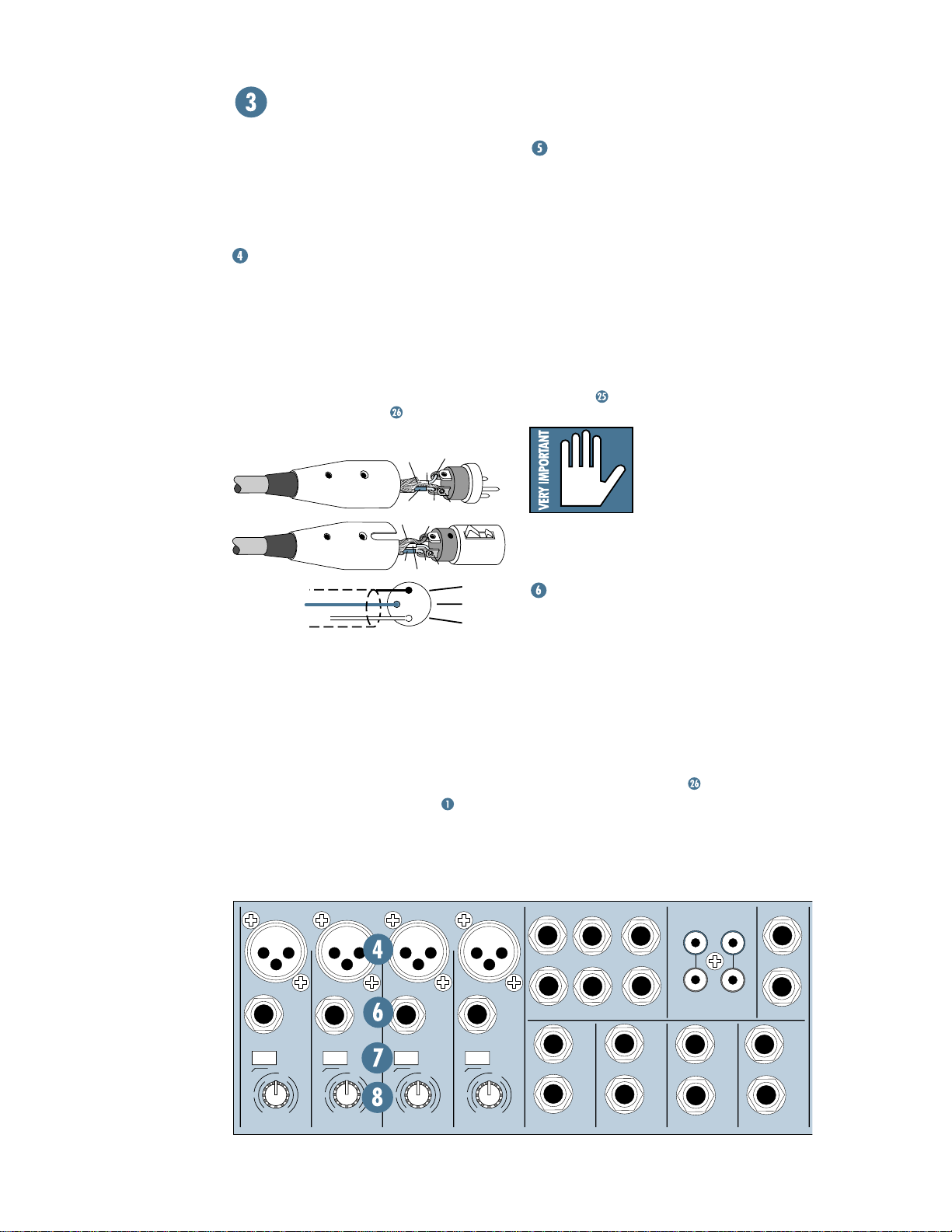
MS1202-VLZ PATCHBAY DESCRIPTION
At the risk of stating the obvious, this is
where you plug everything in: microphones,
line-level instruments and effects, headphones, and the ultimate destination for your
sound: a tape recorder, PA system, etc.
MIC INPUTS (Channels 1–4)
We use phantom-powered, balanced
microphone inputs just like the big studio
mega-consoles, for exactly the same reason:
This kind of circuit is excellent at rejecting
hum and noise. You can plug in almost any
kind of mic that has a standard XLR-type male
mic connector. To learn how signals are
routed from these inputs:
own, connect them like this:
Pin 1 = Ground or shield
Pin 2 = Positive (+ or hot)
Pin 3 = Negative (– or cold)
Professional ribbon, dynamic, and condenser mics will all sound excellent through
these inputs. The MS1202-VLZ’s mic inputs
will handle any kind of mic level you can toss
at them, without overloading. Be sure to perform the Level-Setting Procedure:
. If you wire your
COLD
3
HOT
2
HOT
1
3
1
3
2
1
2
SHIELD
SHIELD
COLD
.
SHIELD
COLD
HOT
PHANTOM POWER
Most modern professional condenser mics
are equipped for Phantom Power, which lets
the mixer send low-current DC voltage to the
mic’s electronics through the same wires that
carry audio. (Semipro condenser mics often
have batteries to accomplish the same thing.)
“Phantom” owes its name to an ability to be
“unseen” by dynamic mics (Shure SM57/SM58,
for instance), which don’t need external power
and aren’t affected by it anyway.
The MS1202-VLZ’s phantom power is globally
controlled by the
rear panel
PHANTOM
switch on the
. (This means the phantom power
for channels 1-4 is turned on and off together.)
Never plug single-ended
(unbalanced) microphones or instruments into
the
MIC
input jacks if the
PHANTOM
power is on.
Do not plug instrument outputs into the
MIC
input jacks with
PHANTOM
power on
unless you know for certain it is safe to do so.
LINE INPUTS (Channels 1–4)
These four line inputs share circuitry (but
not phantom power) with the mic preamps,
and can be driven by balanced or unbalanced
sources at almost any level. You can use these
inputs for virtually any signal you’ll come
across, from instrument levels as low as –30dB
to operating levels of –10dBV to +4dBu, since
there is 30dB more gain available than on
channels
routed from these inputs:
5–12
. To learn how signals are
.
10
MIC
LINE IN 1
M
U
10
+10dB
TRIM
C
I
1
LOW CUT
18dB/OCT
-
1
G
A
I
N
60
-40dB
0
UNBAL
75 Hz
L
BAL
OR
R
TAPE
BAL/UNBAL
MAIN OUTS
LINE IN 11-12
MONO
BAL
UNBAL
L
R
L
OR
R
MONO
1
LEFT
2
LINE IN 5-6
MONO
BAL
UNBAL
RIGHT
RIGHT
L
OR
R
AUX SEND
LINE IN 7-8
MONO
BAL
UNBAL
L
OR
R
1
2
L
R
TAPE
INPUT
LINE IN 9-10
OUTPUT
MONO
UNBAL
-
G
A
-40dB
4
BAL
OR
UNBAL
LOW CUT
75 Hz
18dB/OCT
1
0
I
N
60
LEFT/
STEREO AUX RETURNS
BAL
UNBAL
MIC
OR
LINE IN 4
C
I
M
U
10
+10dB
TRIM
MIC
LINE IN 3
M
U
10
+10dB
TRIM
G
C
I
3
LOW CUT
75 Hz
18dB/OCT
-
1
0
A
I
N
60
-40dB
MIC
2
LINE IN 2
M
U
10
+10dB
TRIM
C
I
LOW CUT
18dB/OCT
-
1
G
A
I
N
60
-40dB
UNBAL
75 Hz
0
BAL
OR
BAL
OR
ALL BAL/UNBAL
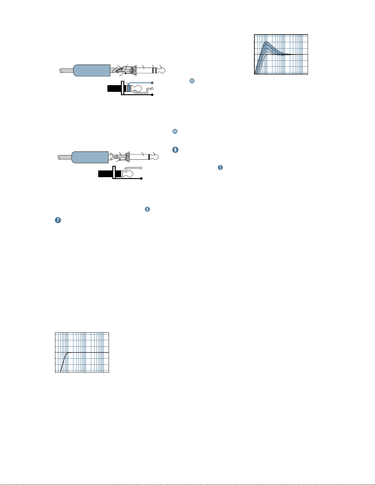
To connect balanced lines to these inputs,
1
use a
⁄4" Tip-Ring-Sleeve (TRS) plug, the type
found on stereo headphones:
SLEEVERING
TIP
RING
Tip = Positive (+ or hot)
Ring = Negative (– or cold)
Sleeve = Shield or ground
To connect unbalanced lines to these
inputs, use a
1
⁄4" mono (TS) phone plug or
standard instrument cable:
TIPSLEEVE
TIP
SLEEVE
Tip = Signal
Sleeve = Ground
LINE IN
inputs 1–4 are a good place to con-
SLEEVE
TIP
nect older instruments that need more gain.
You can correct weak levels by adjusting the
corresponding channel’s
TRIM
control .
LOW CUT (Channels 1–4)
The
LOW CUT
High Pass Filter (all depends on how you look
at it), cuts bass frequencies below 75Hz at a
rate of 18dB per octave.
We recommend that you use
every microphone application except kick
drum, bass guitar, bassy synth patches, or
recordings of earthquakes. These aside, there
isn’t much down there that you want to hear,
and filtering it out makes the low stuff you do
want much more crisp and tasty. Not only that,
but
LOW CUT
of feedback in live situations and it helps to
conserve the amplifier power.
+15
+10
+5
0
–5
–10
–15
20Hz100
Hz
Low Cut
switch, often referred to as a
LOW CUT
can help reduce the possibility
1k
Hz
10kHz20k
Hz
Another way to consider
LOW CUT
’s function is that it
actually adds flexibility during
live performances. With the
TIPSLEEVE
addition of
safely use
vocals.
RING
TIP
shelving
SLEEVE
voices. Trouble is, adding
LOW CUT
LOW
, you can
equalization on
Many times, bass
EQ
can really benefit
LOW EQ
stage rumble, mic handling clunks and breath
pops.
LOW CUT
you can add low
removes all those problems so
EQ
without losing a woofer.
Here’s what the combination of
and
LOW CUT
looks like in terms of
frequency curves.
TRIM (Channels 1–4)
If you haven’t already, please read the Level-
Setting Procedure
TRIM
adjusts the input sensitivity of the mic
and line inputs connected to channels
through 4. This allows signals from the outside
world to be adjusted to optimal internal operating levels.
If the signal originates through the XLR
jack, there will be 10dB of gain with the knob
fully down, ramping to 60dB of gain fully up.
Through the
attenuation fully down and 40dB of gain fully
up, with a “
U
” (unity gain) mark at 9:00. This
10dB of attenuation can be very handy when
on
you are inserting a signal that is very hot, or
when you want to add a lot of
Without this “virtual pad,” a scenario like that
might lead to channel clipping.
.
1
⁄4" input, there is 10dB of
+15
+10
+5
0
–5
–10
–15
20Hz100
Hz
Low Cut with Low EQ
also boosts
LOW EQ
1
EQ
gain, or both.
1k
Hz
10kHz20k
Hz
11
MIC 1
LINE IN 1
M
U
10
+10dB
TRIM
ALL BAL/UNBAL
RIGHT
LEFT/
BAL
OR
STEREO AUX RETURNS
UNBAL
75 Hz
1
0
N
60
MONO
1
LEFT
2
LINE IN 5-6
MONO
UNBAL
BAL
OR
RIGHT
L
R
AUX SEND
LINE IN 7-8
MONO
UNBAL
BAL
OR
L
R
1
2
L
R
TAPE
INPUT
LINE IN 9-10
MIC 2
BAL
OR
UNBAL
LINE IN 2
LOW CUT
75 Hz
18dB/OCT
-
1
0
G
A
C
I
N
I
60
-40dB
LOW CUT
18dB/OCT
-
G
A
C
I
M
U
10
-40dB
+10dB
TRIM
MIC 3
BAL
OR
UNBAL
LINE IN 3
U
+10dB -40dB
10
C
I
M
TRIM
G
A
LOW CUT
18dB/OCT
-
1
I
75 Hz
1
0
I
N
60
MIC 4
BAL
OR
UNBAL
LINE IN 4
75 Hz
0
N
60
LOW CUT
18dB/OCT
-
G
A
C
I
I
M
U
10
-40dB
+10dB
TRIM
TAPE
OUTPUT
MONO
L
BAL
OR
UNBAL
R
BAL/UNBAL
MAIN OUTS
LINE IN 11-12
MONO
UNBAL
L
R
L
BAL
OR
R
PHONES
STEREO LINE INPUTS
(Channels 5–6, 7–8, 9–10 and 11–12)
These fully balanced inputs are designed for
stereo or mono, balanced or unbalanced signals, from –10dBV to +4dBu. They can be used
with just about any professional or semipro
instrument, effect or tape player. To learn how
signals are routed from these inputs:
wire your own cables:
.
In the stereo audio world, an odd-numbered
channel usually receives the “left signal.” For
example, you would feed the MS1202-VLZ’s line
5-6
inputs
left output plug into the channel
a stereo signal by inserting the device’s
5
right output plug into the channel
When connecting a mono device (just one
cord), always use the
(
LINE IN
into the
12
jacks 5, 7, 9 or 11) and plug nothing
RIGHT
)— this way the signal will appear on both
LEFT (MONO)
input (
LINE IN
jacks 6, 8, 10 or
sides. This trick is called “jack normalling”
Serial device
. To
jack, and its
6
jack.
input
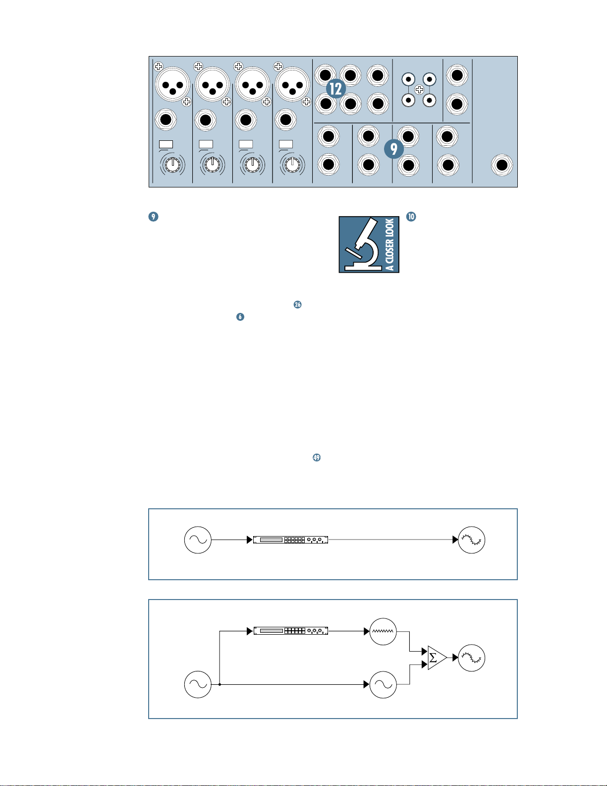
EFFECTS: SERIAL OR
PARALLEL?
The next two sections toss
the terms “serial” and “parallel” around like hacky sacks.
Here’s what we mean by them.
“Serial” means that the entire signal is
routed through the effects device. Examples:
compressor/limiters, graphic equalizers. Linelevel sources can be patched through a serial
effects device before or after the mixer, or preferably through the insert jacks located on the
rear panel (
“Parallel” means that a portion of the signal
in the mixer is tapped off to the device (
SEND
(
STEREO AUX RETURN
original “dry” signal. This way, multiple channels can all make use of the same effects
device. Examples: reverb, digital delay. (See
diagrams below.)
.
CHANNEL INSERT
send/return).
), processed and returned to the mixer
) to be mixed with the
AUX
Dry Signal
Parallel device
Dry Signal(s)
12
Insert
Send
Aux
Send
Signal Processor
(e.g., Compressor)
Signal Processor
(e.g., Reverb)
Channel Path
Insert
Return
Aux
Return
Wet Signal
Dry Signal(s)
Output
Section
Mix
Stage
Processed
Signal
Processed
Signal
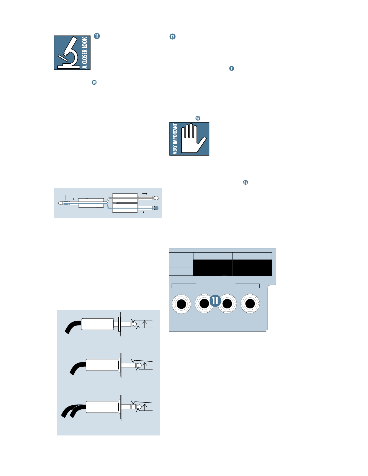
CHANNEL INSERT
E
R
(Channels 1–4 )
These jacks, on the back
of the MicroSeries 1202-VLZ,
are where you connect serial
effects such as compressors, equalizers, deessers, or filters
have more than a few of these gadgets, we’ve
included inserts for just the first four channels. If you want to use this kind of processing
on channels
through the processor before you plug into the
MS1202-VLZ.
The
CHANNEL INSERT
TRIM
and
LOW CUT
channel’s
EQ
(tip) is low-impedance (120 ohms), capable of
driving any line-level device. The return (ring)
is high-impedance (over 2.5k ohms) and can
be driven by almost any device.
Insert cables must be wired thusly:
ring
tip
sleeve
This plug connects to one of the
mixer’s Channel Insert jacks.
Tip = Send (output to effects device)
Ring = Return (input from effects device)
Sleeve = Common ground (connect shield to
all three sleeves)
Besides being used for inserting external
devices, these jacks can also be used as channel direct outputs; post-
and pre
EQ
become so famous that people buy these mixers just to have four of these preamps in their
arsenal. Here’s three ways you can use the
CHANNEL INSERT
. Since most people don’t
5
through 12, simply patch
points are after the
controls, but before the
and
GAIN
controls. The send
(TRS plug)
TRIM
SEND to processor
RETURN from processor
, post-
“tip”
“ring”
LOW CUT
. In fact, Mackie mic preamps have
jacks:
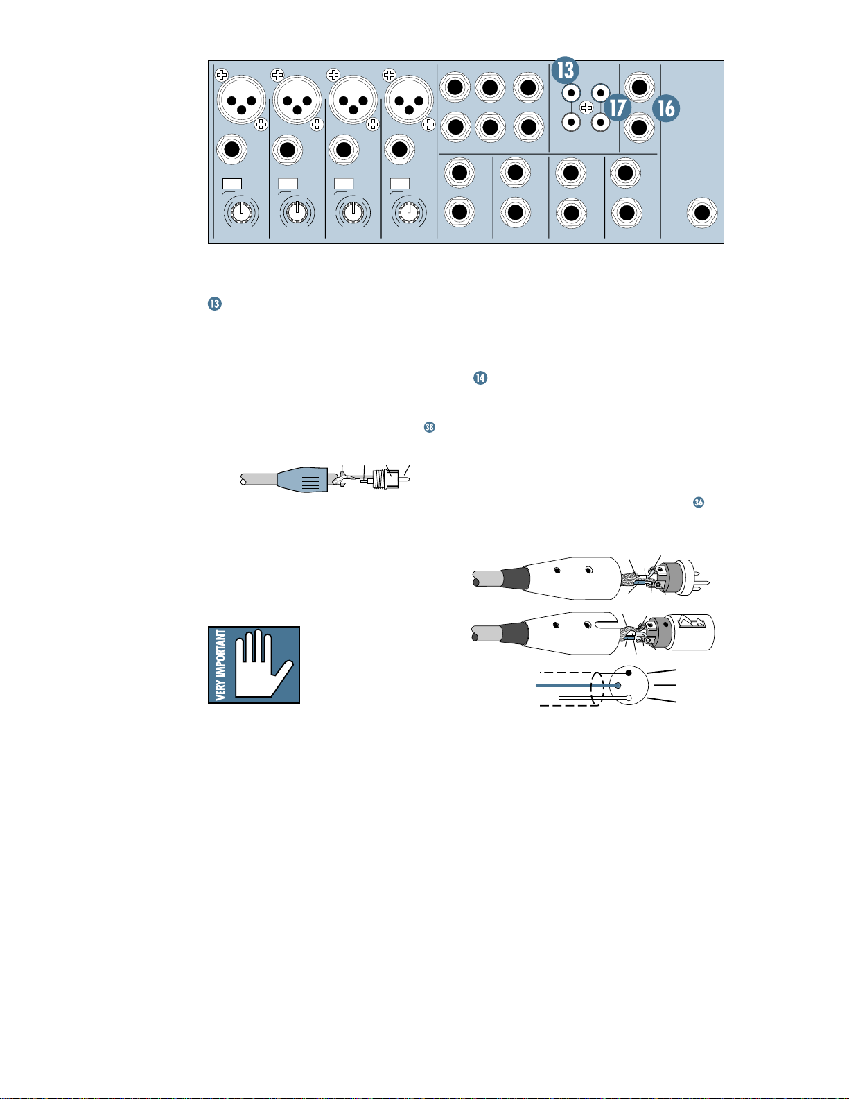
AUX RETURNS
This is where you connect the outputs of
your parallel effects devices (or extra audio
sources). These balanced inputs are similar to
the stereo
Sends, Pan, Mute, and Solo). The circuits will
handle stereo or mono, balanced or unbalanced
signals, either instrument level, –10dBV or
+4dBu. They can be used with just about any
pro or semipro effects device on the market.
To learn how signals are routed from these
inputs, see
unplugged. That way, the unused
TURN 2
AUX RETURN 1
the
vice with a mono output (one cord), plug
that into
MONO
unplugged. That way the signal will be sent
to both sides, magically appearing in the
center as a mono signal. This won’t work
with
R ELECTRIC SHOCK, DO NOT
OT REMOVE COVER.
G TO QUALIFIED PERSONNEL.
OUVRIR
,
CHANGE DE MÊME TYPE.
EMPLACER LE FUSIBLE
LINE IN
inputs (without EQ, Aux
.
One Device: If you have
just one parallel effects
device, use
RETURN 1
STEREO AUX
and leave
REO AUX RETURN 2
level control can be used to feed
to your stage monitors, via
EFX TO MONITOR
switch .
Mono Device: If you have an effects de-
STEREO AUX RETURN 1, LEFT/
, and leave
AUX RETURN 2
(
PRE-FADER / PRE EQ TIP SEND / RING RETURN
4
AUX RETURN 1, RIGHT
— you’ll need a Y-cord.
SERIAL NUMBER
CHANNEL INSERTS
3
2
MANUFACTURING DATE
)
STE-
AUX RE-
,
1
MONO PLUG
Channel Insert jack
Direct out with no signal interruption to master.
Direct out with signal interruption to master.
(TIP = SEND to effect, RING = RETURN from effect.)
Insert only to first “click.”
MONO PLUG
Channel Insert jack
Insert all the way in to the second “click.”
STEREO
PLUG
For use as an effects loop.
Channel Insert jack
KIE DESIGNS INC.
WOODINVILLE WASHINGTON
MADE IN USA
13
MIC 1
LINE IN 1
M
U
10
+10dB
TRIM
ALL BAL/UNBAL
RIGHT
LEFT/
BAL
OR
STEREO AUX RETURNS
UNBAL
75 Hz
1
0
N
60
MONO
1
LEFT
2
LINE IN 5-6
MONO
UNBAL
BAL
OR
RIGHT
L
R
AUX SEND
LINE IN 7-8
MONO
UNBAL
BAL
OR
L
R
1
2
L
R
TAPE
INPUT
LINE IN 9-10
MIC 2
BAL
OR
UNBAL
LINE IN 2
LOW CUT
75 Hz
18dB/OCT
-
1
0
G
A
C
I
N
I
60
-40dB
LOW CUT
18dB/OCT
-
G
A
C
I
I
M
U
10
-40dB
+10dB
TRIM
MIC 3
BAL
OR
UNBAL
LINE IN 3
U
+10dB -40dB
10
C
I
M
TRIM
G
A
LOW CUT
18dB/OCT
-
1
I
75 Hz
1
0
N
60
MIC 4
BAL
OR
UNBAL
LINE IN 4
75 Hz
0
N
60
LOW CUT
18dB/OCT
-
G
A
C
I
I
M
U
10
-40dB
+10dB
TRIM
TAPE
OUTPUT
MONO
L
BAL
OR
UNBAL
R
BAL/UNBAL
MAIN OUTS
LINE IN 11-12
MONO
UNBAL
L
R
L
BAL
OR
R
PHONES
TAPE INPUT
These RCA jacks are designed to work with
semipro as well as pro recorders. To compensate for typically low levels, signals coming in
here will be automatically boosted by 6dB.
Connect your tape recorder’s outputs here,
using standard hi-fi (RCA) cables. To learn how
signals are routed from these inputs, see
Use these jacks for convenient tape playback of your mixes. You’ll be able to review a
mix and then rewind and try another pass
without repatching or disturbing the mixer levels. You can also use these jacks with a
portable tape or CD player to feed music to a
PA system between sets.
WARNING: Engaging
both the
TAPE
and
ASSIGN TO MAIN MIX
buttons in the
SOURCE
matrix can create a feed-
back path between
OUTPUT
. Make sure your tape deck is not
TAPE INPUT
and
in record, record-pause, or input monitor
mode when you engage these switches, or
make sure the
CONTROL ROOM / PHONES
level knob is fully counterclockwise (off).
.
TIPSLEEVETIPSLEEVE
TAPE
Outputs? The MS1202-VLZ has plenty of ’em:
XLR main outputs,
,
OUTPUT
PHONES, CONTROL ROOM
AUX SEND 1
1
⁄4"
MAIN OUTS
and 2. Let’s take a peek.
, RCA
TAPE
and
XLR MAIN OUTS
These low-impedance outputs are fully balanced and capable of driving +4dBu lines with
up to 28dB of headroom. This output is 6dB
hotter than other outputs (noted on the
MIX
level pot by a special “
left of the “
U
” center detent position). To learn
U BAL
how signals are routed to these outputs:
To use these outputs, wire the XLR
(balanced only) connectors like this:
SHIELD
HOT
3
COLD
SHIELD
1
3
COLD
HOT
1
3
2
Pin 1 = Ground
Pin 2 = Positive (+ or hot)
Pin 3 = Negative (– or cold)
MAIN
” mark, just
2
1
2
SHIELD
COLD
HOT
.
14
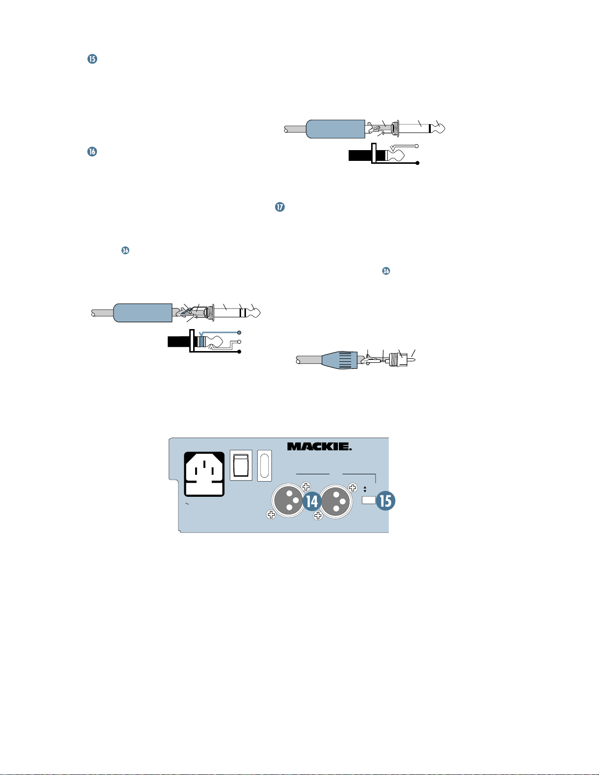
XLR MAIN OUTPUT LEVEL SWITCH
Engaging the
pads the balanced XLR main outputs by 30dB,
so you can feed the microphone input of, say,
another mixer.
You can safely connect this output into an
input that provides 48V phantom power.
MAIN OUTPUT LEVEL
switch
1⁄4" MAIN OUTS
These 1⁄4" jacks are balanced outputs capable of delivering 22dBu into a 600 ohm
balanced or unbalanced load. (Okay, we admit
it, that was a pretty technical sentence. See
the Glossary and Connections appendices if
you want to decode it.)
To learn how signals are routed to these
outputs:
To use these outputs to drive balanced inputs, connect
phone plugs like this:
Tip = + (hot)
Ring = – (cold)
Sleeve = Ground
.
1
⁄4" TRS (Tip-Ring-Sleeve)
SLEEVERING
TIP
RING
TIPSLEEVE
RING
TIP
SLEEVE
For most music recording and PA applications, unbalanced lines are perfectly
acceptable. To use these outputs to drive unbalanced inputs, connect
1
⁄4" TS (Tip-Sleeve)
phone plugs like this:
SLEEVE
TIP
Tip = + (hot)
Sleeve = Ground
TAPE OUTPUT
These unbalanced RCA connections tap the
main output
1
⁄4"
and PA work more convenient. Connect these
to your recorder’s inputs. To learn how signals
are routed to these outputs:
Mono Out: If you want to feed a mono signal
to your tape deck or other device, simply use
an RCA Y-cord to combine these outputs
(Radio Shack
attempt this with any other outputs on the
MS1202-VLZ.
to make simultaneous recording
.
®
#42-4235, for instance). Do not
TIPSLEEVE
TIP
SLEEVE
TIPSLEEVETIPSLEEVE
120 VAC 50/60 Hz 20W
315mA/250V SLO-BLO
CAUTION:
TO REDUCE THE RISK OF
FIRE REPLACE WITH SAME
TYPE FUSE AND RATING
ON
POWER
ON
PHANTOM
MICRO SERIES
1202-VLZ
LOW NOISE HIGH HEADROOM
12-CHANNEL MIC/LINE MIXER
RIGHT
LEFT
TM
+4
MIC
MAIN
OUTPUT
LEVEL
15
 Loading...