

Page 1
MixerMixer
Unity Gain Active Combiner
AUX 1
MONITOR
AUX 2
AUX 3
AUX 4
AUX 5
AUX 6
ALT 3
MIXER MIXER
UNITY GAIN COMBINER
POWER
COMBINED
OUT
INPUTS
COMBINED
COMBINED
COMBINED
COMBINED
COMBINED
COMBINED
+22
+22
+22
+22
+22
+22
MAX
MAX
MAX
MAX
OUT
OUT
INPUTS
OUT
INPUTS
1
2
3
INPUTS
1
1
2
2
3
3
MAX
OUT
OUT
INPUTS
INPUTS
1
1
2
2
3
3
+22
MAX
MAX
OUT
INPUTS
1
1
2
2
3
3
COMBINED
OUT
INPUTS
ALT 4
COMBINED
PHONES OUT
+22
+22
MAX
MAX
OUT
TIP= LEFT RING=RIGHT
PHONE INPUTS
INPUTS
FROM
PHONES
OUT
1
2
3
(TRX)
1
FROM
PHONES
OUT
2
(TRX)
FROM
PHONES
OUT
(TRX)
3
COMBINED
+22
MAX
1
2
3
MAIN COMBINED BALANCED OUTPUTS
LEFT RIGHT MONO
+22
+22
MAX
MAX
L INPUTS
R INPUTS
1
1
2
2
3
3
Optional
Remote
Fader
+22
MAX
A
LIGNMENT
REMOTE MASTER
NOTCH
DEPRESS FOR USE WITH
1
REMOITE MASTER FADER
MAIN INSERT
L
MADE IN THE USA
R
REMOTE MASTER
+dB
10
5
U
5
10
15
20
25
30
35
40
OO
dB
What it is
We called it the MixerMixer because that’s
what it does... it mixes the outputs from up to
three mixers so you can use them as if they
were one bigger mixer.
Combining the outputs of two or more
mixers has always been a difficult task. At best
you could combine main outputs by giving up
two inputs on one of the mixers. However,
none of the AUX sends or headphone monitoring functions could be combined .
The Mixer Mixer solves this problem,
combining ALL outputs from up to three
mixers and providing a new set of outputs for
up to three mixers. For example, three Mackie
Designs CR-1604's and a MixerMixer gives
you 48 line inputs, 18 MIC inputs, 12 stereo
effects returns and 24 direct outs!
Since all combining is at unity gain, you lose
no level or head room — and gain no additional
noise. In fact, the MixerMixer's noise level is so
low that you can use it at
–10dB or +4dB levels.
Remote Fader
With the addition of the
optional remote fader, you
can control the main L/R
output level of all the mixers
that are plugged into the
MixerMixer. The remote
fader comes with its own
connecting cable. Bolt it to
the side of one of your
CR-1604’s, hold it in your
hand, stand it on a table, or
use double-backed tape to
mount it anywhere that’s
convenient to use.
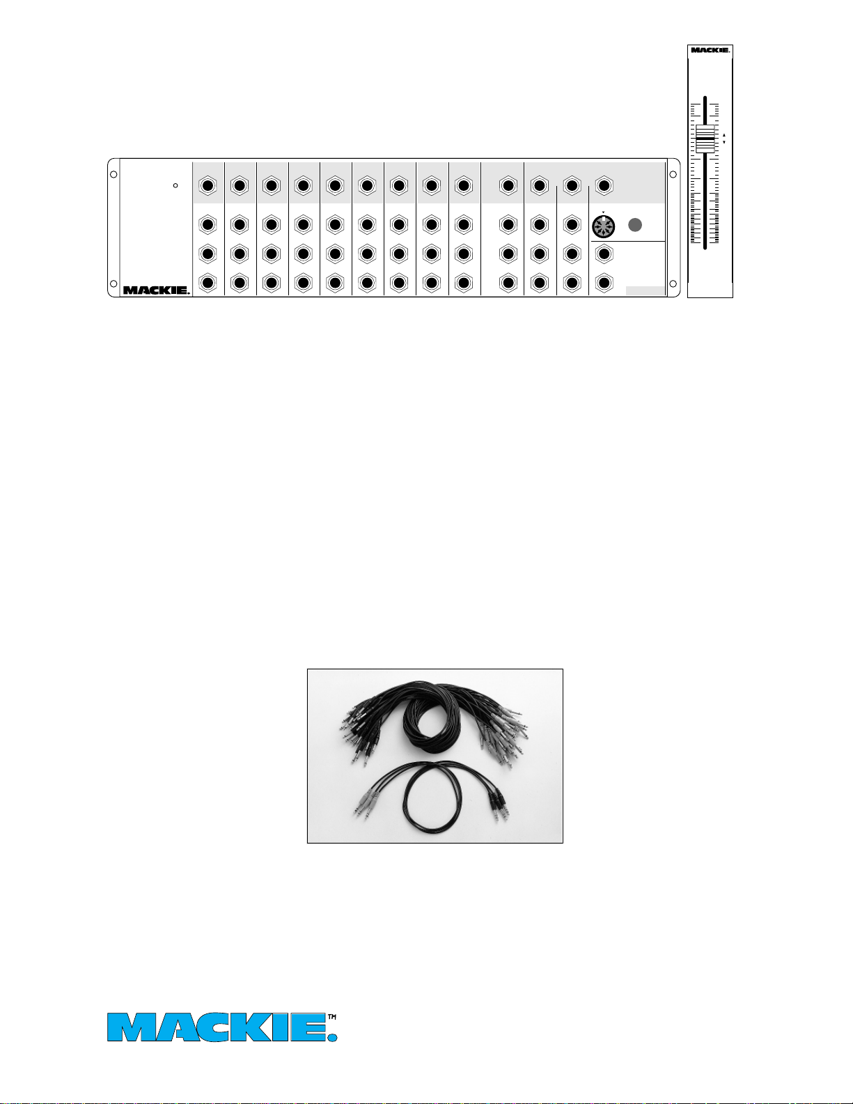
CordPack: The economical patch cord solution. It
takes a lot of cables to link three CR-1604s. So we
offer thirty-six mono and three stereo patch cords for
a VERY reasonable price. These are high quality
cables with molded construction, plated contact
surfaces, flexible insulation and different colored ends
to make identifying inputs and outputs easy.
CordPack
Use the available cord pack to interconnect
CR-1604’s and MixerMixers. CordPacks
include all the cables needed to connect up to
three CR-1604’s to a MixerMixer.
Connections
MixerMixer is really, really easy to hook up.
Just connect all the various outputs from your
mixers to the inputs of the MixerMixer. The
new, combined outputs from your system are
taken from the Mixer Mixer.
If you are using the remote fader, be sure to
position the plug correctly when you plug into
the Mixer Mixer. The alignment notch is clearly
marked on the MixerMixer to correspond with
the “dent” in the end casing of the DIN plug
on the cable supplied.
NOTE:The reason it’s even possible to
insert the plug incorrectly is because we put a
seven- pin DIN connector in the MixerMixer
that allows us to give you some specialized
control functions at a later date (the other pins
supply power).
Enabling the Remote Fader
To use the remote fader you must depress
the switch that lurks behind the MixerMixer’s
front panel, right along
side the DIN plug
socket. It’s recessed for
security, so you have to
very deliberately insert a
pencil (or non-conductive pen) through the
small hole to depress
the switch. MixerMixers
are shipped from the
factory with the switch
in the “remote-off”
position.
Sub-mixing With the
Remote Fader
With the remote fader
you can use the existing
master output sliders for
sub-masters. Use the pan controls to assign
each channel to the appropriate output submaster, then use the remote fader to set the
overall output level.
(continued on back page)
Page 2
REMOTE MASTER
+22
MAX
NOTCH
ALIGNMENT
+22
MAX
R INPUTS
+22
MAX
LEFT RIGHT MONO
MAIN COMBINED BALANCED OUTPUTS
L INPUTS
+22
MAX
COMBINED
TIP= LEFT RING=RIGHT
PHONES OUT
ALT 4
COMBINED
ALT 3
COMBINED
AUX 6
COMBINED
AUX 5
COMBINED
AUX 4
COMBINED
AUX 3
COMBINED
AUX 2
COMBINED
MONITOR
COMBINED
AUX 1
COMBINED
UNITY GAIN COMBINER
MIXER MIXER
POWER
+22
MAX
+22
MAX
+22
MAX
+22
MAX
+22
MAX
+22
MAX
+22
MAX
+22
MAX
+22
MAX
PHONE INPUTS
OUT
INPUTS
OUT
INPUTS
OUT
INPUTS
OUT
INPUTS
OUT
INPUTS
OUT
INPUTS
OUT
INPUTS
OUT
INPUTS
OUT
INPUTS
OUT
FROM
PHONES
HEADPHONE output on
top of CR-1604
MADE IN THE USA
MAIN INSERT
DEPRESS FOR USE WITH
REMOITE MASTER FADER
1
L
R
MAINS PHANTOM
1
2
3
MAIN
OUT
1
2
3
1
2
3
OUT
OUT
(TRX)
(TRX)
(TRX)
FROM
FROM
PHONES
PHONES
1
2
3
1
2
3
1
2
3
1
2
3
1
2
3
1
2
3
1
2
3
1
2
3
1
2
3
LEFT
RIGHT
MAIN
OUT
LEFT
RIGHT
MAIN
OUT
LEFT
RIGHT
MONITOR
MONITOR
MONITOR
MONO
4
MAINS PHANTOM
MONO
4
MAINS PHANTOM
MONO
4
+48V
AUX OUT
HEADPHONE output on
top of CR-1604
+48V
AUX OUT
HEADPHONE output on
top of CR-1604
+48V
AUX OUT
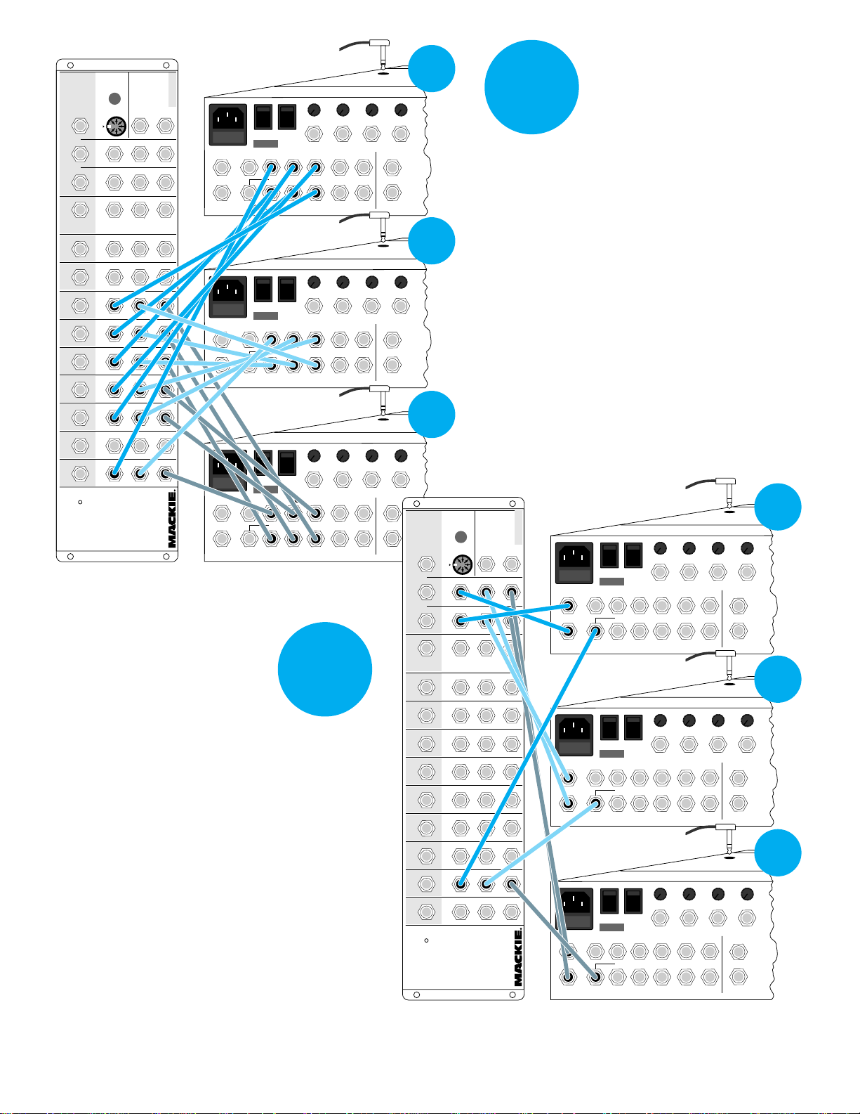
B1. Using mono
patchcords, connect the MONITOR
outputs of each
CR-1604 to the MONITOR INPUTS on the
MixerMixer.
B2. Using mono
patchcords, connect the
MAIN OUTPUTS of each
CR-1604 to the left and
right MAIN INPUTS on
the MixerMixer. Each
main fader on the CR1604 becomes a
submaster.
•
•
–10
–10
+4 –40
+4 –40
U
U
15
16
ALT 3/4
LEFT
36251
RIGHT
•
•
–10
–10
+4 –40
+4 –40
U
U
15
16
ALT 3/4
LEFT
36251
RIGHT
•
•
–10
–10
+4 –40
+4 –40
U
U
15
16
ALT 3/4
LEFT
36251
RIGHT
B
BUSS
INSERT
RIGHT
BUSS
INSERT
RIGHT
BUSS
INSERT
RIGHT
LEFT
LEFT
LEFT
–10
+4 –40
U
–10
+4 –40
U
–10
+4 –40
U
1
•
•
–10
+4 –40
U
13
14
A
Attack of the patchcord
spiderweb! Using mono
patch cords, connect the
AUX OUTPUTS of each
L
1
R
CR-1604 to the AUX INPUTS on the MixerMixer. It
really isn’t as daunting as it
looks. The only critical
2
•
•
–10
+4 –40
U
13
14
detail is to make sure that
the AUX OUT numbers on
the mixer correspond with
the numbered AUX inputs
on the MixerMixer, i.e. AUX
L
1
R
4 on the CR-1604s go to
the AUX 4 INPUTs on the
MixerMixer, etc.
3
•
•
–10
+4 –40
U
13
14
HEADPHONE output on
MAINS PHANTOM
MONO
4
MAINS PHANTOM
MONO
4
MAINS PHANTOM
MONO
4
top of CR-1604
•
•
–10
–10
+4 –40
+4 –40
U
U
16
+48V
AUX OUT
+48V
AUX OUT
+48V
AUX OUT
ALT 3/4
LEFT
36251
RIGHT
HEADPHONE output on
top of CR-1604
•
•
–10
–10
+4 –40
+4 –40
U
U
16
ALT 3/4
LEFT
36251
RIGHT
HEADPHONE output on
top of CR-1604
•
•
–10
–10
+4 –40
+4 –40
U
U
16
ALT 3/4
LEFT
36251
RIGHT
1
•
•
–10
–10
+4 –40
+4 –40
U
U
13
14
15
BUSS
INSERT
L
LEFT
1
R
RIGHT
2
•
•
–10
–10
+4 –40
+4 –40
U
U
13
14
15
BUSS
INSERT
L
LEFT
1
R
RIGHT
3
•
•
–10
–10
+4 –40
+4 –40
U
U
13
14
15
BUSS
INSERT
L
LEFT
1
R
RIGHT
L
1
R
REMOTE MASTER
+22
MAX
NOTCH
ALIGNMENT
+22
MAX
R INPUTS
+22
MAX
LEFT RIGHT MONO
MAIN COMBINED BALANCED OUTPUTS
L INPUTS
+22
MAX
COMBINED
TIP= LEFT RING=RIGHT
PHONES OUT
ALT 4
COMBINED
ALT 3
COMBINED
AUX 6
COMBINED
AUX 5
COMBINED
AUX 4
COMBINED
AUX 3
COMBINED
AUX 2
COMBINED
MONITOR
COMBINED
AUX 1
COMBINED
UNITY GAIN COMBINER
MIXER MIXER
POWER
+22
MAX
+22
MAX
+22
MAX
+22
MAX
+22
MAX
+22
MAX
+22
MAX
+22
MAX
+22
MAX
PHONE INPUTS
OUT
INPUTS
OUT
INPUTS
OUT
INPUTS
OUT
INPUTS
OUT
INPUTS
OUT
INPUTS
OUT
INPUTS
OUT
INPUTS
OUT
INPUTS
OUT
FROM
PHONES
DEPRESS FOR USE WITH
REMOITE MASTER FADER
1
1
1
1
(TRX)
1
1
1
1
1
1
1
1
1
MADE IN THE USA
MAIN INSERT
L
R
2
3
MAIN
OUT
2
3
2
3
OUT
OUT
(TRX)
(TRX)
FROM
FROM
PHONES
PHONES
2
3
2
3
2
3
2
3
2
3
2
3
2
3
2
3
2
3
LEFT
RIGHT
MAIN
OUT
LEFT
RIGHT
MAIN
OUT
LEFT
RIGHT
MONITOR
MONITOR
MONITOR
Page 3

REMOTE MASTER
+22
MAX
NOTCH
ALIGNMENT
+22
MAX
R INPUTS
+22
MAX
LEFT RIGHT MONO
MAIN COMBINED BALANCED OUTPUTS
L INPUTS
+22
MAX
COMBINED
TIP= LEFT RING=RIGHT
PHONES OUT
ALT 4
COMBINED
ALT 3
COMBINED
AUX 6
COMBINED
AUX 5
COMBINED
AUX 4
COMBINED
AUX 3
COMBINED
AUX 2
COMBINED
MONITOR
COMBINED
AUX 1
COMBINED
UNITY GAIN COMBINER
MIXER MIXER
POWER
+22
MAX
+22
MAX
+22
MAX
+22
MAX
+22
MAX
+22
MAX
+22
MAX
+22
MAX
+22
MAX
PHONE INPUTS
OUT
INPUTS
OUT
INPUTS
OUT
INPUTS
OUT
INPUTS
OUT
INPUTS
OUT
INPUTS
OUT
INPUTS
OUT
INPUTS
OUT
INPUTS
OUT
FROM
PHONES
DEPRESS FOR USE WITH
REMOITE MASTER FADER
1
1
1
1
(TRX)
1
1
1
1
1
1
1
1
1
HEADPHONE output on
top of CR-1604
•
•
•
+48V
AUX OUT
4
–10
+4 –40
U
16
36251
MADE IN THE USA
MAIN INSERT
L
R
LEFT
RIGHT
MAINS PHANTOM
MONO
MONITOR
2
3
MAIN
OUT
2
3
2
3
OUT
OUT
(TRX)
(TRX)
FROM
FROM
PHONES
PHONES
2
3
–10
–10
+4 –40
+4 –40
U
U
14
15
BUSS
INSERT
ALT 3/4
LEFT
LEFT
RIGHT
RIGHT
HEADPHONE output
on top of CR-1604
L
R
–10
+4 –40
U
1
1
•
13
C
Using mono patch
cords, connect the
ALT 3 and ALT 4
OUTPUTS of each
CR-1604 to the
ALT 3 and ALT 4
inputs on the
MixerMixer.
2
2
3
2
3
2
3
MAIN
OUT
2
3
2
3
2
3
2
3
2
3
MAIN
OUT
LEFT
RIGHT
LEFT
RIGHT
MONO
MONITOR
MONO
MONITOR
MAINS PHANTOM
+48V
AUX OUT
4
HEADPHONE output on
top of CR-1604
MAINS PHANTOM
+48V
AUX OUT
4
–10
+4 –40
U
–10
+4 –40
U
•
•
16
36251
16
36251
•
–10
+4 –40
U
15
ALT 3/4
LEFT
RIGHT
•
–10
+4 –40
U
15
ALT 3/4
LEFT
RIGHT
BUSS
INSERT
LEFT
RIGHT
BUSS
INSERT
LEFT
RIGHT
–10
–10
•
+4 –40
U
14
•
+4 –40
U
14
•
–10
+4 –40
U
13
L
1
R
D
3
•
–10
+4 –40
U
13
L
1
R
MixerMixer
Using STEREO
patch cords, connect the HEADPHONE outputs of
each CR-1604 to
the PHONE INPUTS
inputs on the
MixerMixer.
14 15 16 PHANTOM MAINS
The Remote Master can
be fastened to the right side
of the CR-1604.
Remove the left side
sheet metal from the
1
2
3
4
MONO
AUX
SOLO
ALT PREVIEW
REMOTE MASTER
MAIN OUTPUT
MUTE
SOLO
TO
MAIN
+dB
10
5
U
SOLO/PHONES
5
10
15
20
25
30
35
40
OO
dB
Remote Master
by taking out
the two sheet
metal screws
on the side of
the unit and
two more on
the bottom.
Next remove
the two bottom
MON
SOLO
16
MUTE
ALT 3/4
1
2
345
5/6
SHIFT
AUX
U
+1500
U
+1500
U
+1500
U
6
+1500
0
HI
+15–15
0
MID
+15–15
0
LO
+12–12
EQ
0
RL
PAN
OL
+20
U
00
STEREO AUX RETURNS
U
C
1
1
+1500
RL
U
C
2
2
+1500
RL
U
C
3
3
+1500
RL
U
C
4
4
+1500
RL
LEVEL BALANCE
CR1604
16 CHANNEL MIC/LINE MIXER
CLIP
+8
+4
+2
0
-4
-8
-12
-16
-20
POWER
SOLO
LEVEL
1/LEFT 2/RIGHT LEVEL
+10
00 00
right side screws on the CR-1604 main
chassis.
Attach the left side sheet metal panel
to the side of the CR-1604 with the same
two screws you just removed.
Now attach the rest of the Remote
Master via the screws on the bottom of
the unit.
REMOTE MASTER
MIXER MIXER
UNITY GAIN COMBINER
POWER
AUX 1
COMBINED
OUT
INPUTS
Make connections
E
to equipment from
the COMBINED
outputs along the
top of the
MixerMixer
REMOTE MASTER
NEW COMBINED OUTPUTS
MONITOR
AUX 2
AUX 3
AUX 4
AUX 5
AUX 6
ALT 3
COMBINED
COMBINED
COMBINED
COMBINED
COMBINED
COMBINED
+22
+22
+22
+22
+22
MAX
MAX
MAX
INPUTS
MAX
OUT
OUT
INPUTS
1
1
2
2
3
3
OUT
INPUTS
1
1
2
2
3
3
INPUTS
+22
MAX
MAX
OUT
OUT
OUT
INPUTS
INPUTS
1
1
2
2
3
3
ALT 4
COMBINED
COMBINED
+22
+22
INPUTS
+22
MAX
MAX
OUT
OUT
INPUTS
1
1
2
2
3
3
MAX
1
2
3
COMBINED
PHONES OUT
TIP= LEFT RING=RIGHT
PHONE INPUTS
FROM
PHONES
OUT
(TRX)
FROM
PHONES
OUT
(TRX)
FROM
PHONES
OUT
(TRX)
MAIN COMBINED BALANCED OUTPUTS
LEFT RIGHT
+22
+22
MAX
MAX
L INPUTS
R INPUTS
1
1
2
2
3
3
+22
MAX
ALIGNMENT
REMOTE MASTER
NOTCH
DEPRESS FOR USE WITH
1
1
REMOITE MASTER FADER
MAIN INSERT
2
L
MADE IN THE USA
3
R
+dB
10
5
U
5
10
15
20
25
30
35
40
OO
dB
Page 4

MixerMixer
INPUTS
INPUTS
HEAD PHONE COMBINER
1
2
3
AUX & ALT 3-4 COMBINERS
1
2
3
MIX
AMP
MIX
AMP
MIX
AMP
OUT
OUT
L
INPUTS
R
MAIN
LEFT
INSERT
1
2
MIX
3
1
2
3
16.2"
AMP
MIX
AMP
MAIN
RIGHT
INSERT
MAIN LEFT/RIGHT COMBINER
REMOTE
MASTER
FADER
SWITCH
(shown out)
+
+10dB
+
+10dB
REMOTE
FADER
OPTION
–
+
–
+
–
+
MAIN LEFT
BALANCED
OUT
MAIN MONO
BALANCED
OUT
MAIN LEFT
BALANCED
OUT
4.0"3.0"
15.7"
16.7"
Studio Monitoring
When used in studio applications, the monitor
amplifier can be driven from the MixerMixer’s
combined HEADPHONE output. If your power
amplifier has input level controls, set them at 12
o’clock to compensate for the extremely high
output level of the headphone driver.
Tape Outputs
Outputs to 2-track tape recorders are derived
from main combined LEFT and RIGHT MixerMixer outputs. Multiple recorders can easily be
driven simply by adding "Y" cords to the output.
©1995 Mackie Designs™ Inc. Printed in USA
PART NO. 820-003-00 v1.1r1/95
1.65"
MixerMixer Specifications
Frequency
Response: 20Hz to 40kHz +0dB –1dB
Distortion: 0.05% 20Hz to 20kHz
Hum & Noise: –94dBu ref. +4dB operating level
20kHz NBW
Dynamic
Range: 124dB 400Hz to 40kHz
Crosstalk: –84dB @1kHz
Power: 5 watts
Shipping
Weight: w/o Remote Fader 5 lbs.
with Remote Fader 7 lbs.
MACKIE DESIGNS INC. • 16220 Wood-Red Rd. NE
WOODINVILLE • WA • 98072 • USA • 800-258-6883
OUTSIDE THE U.S. 206/487-4333 • FAX 206/487-4337
 Loading...