

Mackie Mix10fxP Owner's Manual


CAUTION AVIS
pag
RISK OF ELECTRIC SHOCK
DO NOT OPEN
RISQUE DE CHOC ELECTRIQUE
NE PAS OUVRIR
CAUTION: TO REDUCE THE RISK OF ELECTRIC SHOCK
DO NOT REMOVE COVER (OR BACK)
NO USER-SERVICEABLE PARTS INSIDE
REFER SERVICING TO QUALIFIED PERSONNEL
ATTENTION: POUR EVITER LES RISQUES DE CHOC
ELECTRIQUE, NE PAS ENLEVER LE COUVERCLE. AUCUN
ENTRETIEN DE PIECES INTERIEURES PAR L'USAGER. CONFIER
L'ENTRETIEN AU PERSONNEL QUALIFIE.
AVIS: POUR EVITER LES RISQUES D'INCENDIE OU
D'ELECTROCUTION, N'EXPOSEZ PAS CET ARTICLE
A LA PLUIE OU A L'HUMIDITE
The lightning flash with arrowhead symbol within an equilateral
triangle is intended to alert the user to the presence of uninsulated
“dangerous voltage” within the product’s enclosure that may be
of sufficient magnitude to constitute a risk of electric shock to persons.
Le symbole éclair avec point de flèche à l'intérieur d'un triangle
équilatéral est utilisé pour alerter l'utilisateur de la présence à
l'intérieur du coffret de “voltage dangereux” non isolé d'ampleur
suffisante pour constituer un risque d'éléctrocution.
The exclamation point within an equilateral triangle is intended to
alert the user of the presence of important operating and maintenance
(servicing) instructions in the literature accompanying the appliance.
Le point d'exclamation à l'intérieur d'un triangle équilatéral est
employé pour alerter les utilisateurs de la présence d'instructions
importantes pour le fonctionnement et l'entretien (service) dans le
livret d'instruction accom
nant l'appareil.
SAFETY INSTRUCTIONS
1. Read these instructions.
2. Keep these instructions.
3. Heed all warnings.
4. Follow all instructions.
5. Do not use this apparatus near water.
6. Clean only with a dry cloth.
7. Do not block any ventilation openings. Install in accordance
with the manufacturer’s instructions.
8. Do not install near any heat sources such as radiators, heat
registers, stoves, or other apparatus (including amplifi ers) that
produce heat.
9. Do not defeat the safety purpose of the polarized or
grounding-type plug. A polarized plug has two blades with
one wider than the other. A grounding-type plug has two
blades and a third grounding prong. The wide blade or
the third prong are provided for your safety. If the provided
plug does not fi t into your outlet, consult an electrician for
replacement of the obsolete outlet.
10. Protect the power cord from being walked on or pinched
particularly at plugs, convenience receptacles, and the point
where they exit from the apparatus.
11. Only use attachments/accessories specifi ed by the
manufacturer.
12. Use only with a cart, stand, tripod, bracket, or table specifi ed
by the manufacturer, or sold with the apparatus. When a
cart is used, use caution when moving the cart/apparatus
combination to avoid injury from tip-over.
13. Unplug this apparatus during lightning storms or when unused
for long periods of time.
14. Refer all servicing to qualifi ed service personnel. Servicing
is required when the apparatus has been damaged in any
way, such as when the power-supply cord or plug has been
damaged, liquid has been spilled or objects have fallen into
the apparatus, the apparatus has been exposed to rain or
moisture, does not operate normally, or has been dropped.
15. This apparatus shall not be exposed to dripping or splashing,
and no object fi lled with liquids, such as vases, shall be
placed on the apparatus.
16. This apparatus has been designed with Class-I construction
and must be connected to a mains socket outlet with a
protective earthing connection (the third grounding prong).
17. The MAINS plug or an appliance coupler is used as the
disconnect device, so the disconnect device shall remain
readily operable.
18. This apparatus has been equipped with a double-pole AC
mains power switch. This switch is located on the rear panel
and should remain readily accessible to the user.
19. NOTE: This equipment has been tested and found to comply
with the limits for a Class B digital device, pursuant to part
15 of the FCC Rules. These limits are designed to provide
reasonable protection against harmful interference in a
residential installation. This equipment generates, uses, and
can radiate radio frequency energy and, if not installed and
used in accordance with the instructions, may cause harmful
interference to radio communications. However, there is no
guarantee that interference will not occur in a particular
installation. If this equipment does cause harmful interference
to radio or television reception, which can be determined by
turning the equipment off and on, the user is encouraged to
try to correct the interference by one or more of the following
measures:
• Reorient or relocate the receiving antenna.
• Increase the separation between the equipment and
the receiver.
• Connect the equipment into an outlet on a circuit
different from that to which the receiver is connected.
• Consult the dealer or an experienced radio/TV
CAUTION: Changes or modifi cations to this device not
20.
technician for help.
expressly approved by LOUD Technologies Inc. could void the
user's authority to operate the equipment under FCC rules.
This apparatus does not exceed the Class A/Class B
(whichever is applicable) limits for radio noise emissions
from digital apparatus as set out in the radio interference
regulations of the Canadian Department of Communications.
ATTENTION —Le présent appareil numérique n’émet pas de bruits
radioélectriques dépassant las limites applicables aux appareils numériques
de class A/de class B (selon le cas) prescrites dans le règlement sur le
brouillage radioélectrique édicté par les ministere des communications du
Canada.
21.
Exposure to extremely high noise levels may cause permanent
hearing loss. Individuals vary considerably in susceptibility to
noise-induced hearing loss, but nearly everyone will lose some
hearing if exposed to suffi ciently intense noise for a period of
time. The U.S. Government’s Occupational Safety and Health
Administration (OSHA) has specifi ed the permissible noise level
exposures shown in the following chart.
According to OSHA, any exposure in excess of these
permissible limits could result in some hearing loss. To ensure
against potentially dangerous exposure to high sound
pressure levels, it is recommended that all persons exposed to
equipment capable of producing high sound pressure levels
use hearing protectors while the equipment is in operation.
Ear plugs or protectors in the ear canals or over the ears must
be worn when operating the equipment in order to prevent
permanent hearing loss if exposure is in excess of the limits set
forth here:
PORTABLE CART WARNING
2
Carts and stands - The
Component should be used
only with a cart or stand
that is recommended by
the manufacturer.
A Component and cart
combination should be
moved with care. Quick
stops, excessive force, and
uneven surfaces may cause
the Component and cart
combination to overturn.
Duration Per Day Sound Level dBA, Typical
In Hours Slow Response Example
8 90 Packed garage concert
6 92
4 95 VW Bus Peace Train
3 97
2 100 Cranked psychedelic tunes
1.5 102
1 105 High speed chase on C.H.I.P.s
0.5 110
0.25 or less 115
Loudest parts at a Heavy Metal concert
WARNING — To reduce the risk of fi re
or electric shock, do not expose this
appliance to rain or moisture.

Contents
Safety Instructions .....................................2
Getting Started ..........................................4
Introduction ...............................................5
Hookup Diagrams .....................................6
Rear Panel Features ................................10
1. Power Connection ..................10
2. Power Switch ............................10
3. Speaker-level Outputs .............11
4. Ventilation .................................11
Front Panel Features ...............................12
Connector Section .............................12
5. Mic Inputs..................................12
6. Mono Line Inputs ......................13
7. Stereo Line Inputs .....................13
8. RCA Inputs ................................13
9. Monitor Send ...........................13
10. Tape Outputs ...........................13
11. Main Outputs ...........................13
12. Power Amp Mode Switch .......14
13. Power Amp Inputs ..................14
Channel Controls ................................15
14. High EQ .....................................16
15. Mid EQ .......................................16
16. Low EQ ......................................16
17. Aux Send Mon ..........................17
18. Aux Send FX ..............................17
19. Overload (OL) Led ...................17
20. Channel Level ..........................17
21. Gain Switch ..............................17
Master Controls ...................................18
22. Power Led .................................18
23. Phantom Switch and Led .......18
24. Break Switch and Led .............18
25. Main Master Graphic EQ ........18
26. Main Mix Meters .......................19
27. FX To Main .................................19
28. Main Master Level ....................19
29. Monitor Graphic EQ ................19
30. Monitor Meter ...........................19
31. FX To Monitor ............................19
32. Monitor Master Level ...............20
33. Series 69 EQ ..............................20
Internal Effects .....................................20
34. Preset Selector .........................20
35. OL Led .......................................20
Table of Internal Effects .................21
Appendix A: Service Information ..........22
Appendix B: Connections ......................23
Appendix C: Technical Information ......24
TAPCO Limited Warranty ........................27
Don’t forget to visit our website at www.tapcoworld.com
for more information about this and other TAPCO products.
What me, read a manual?
Your new TAPCO® powered mixer is designed to bring you great joy, as you share your
wonderful skills and love of music with the world. Before you begin, make sure you read the
safety instructions on page 2 and getting started on page 4. You can read the rest of the
manual whenever you get a free moment in your busy schedule.
It is important to keep your receipt in a safe place, and not a bad idea to write your
product information here for future reference (i.e., insurance claims, tech support, return
authorization, etc.).
Product Serial #:
Purchased at:
Date of purchase:
Part No. SW0696 Rev. B 08/08
©2006-2008 LOUD Technologies Inc. All Rights Reserved.
3

Getting Started
We realize that you must be
really keen to try out your new
powered mixer, but please
read the safety instructions on
page 2, and this page fi rst.
SETUP
1. Place the powered mixer in a position
where it is easy to reach the controls.
All the controls and input connections
are located on the front panel so you
can make quick adjustments and
connections on stage.
2. Make sure there is at least 6 inches of
airspace behind the powered mixer for
ventilation. Use the powered mixer in a
nice clean and dry environment.
CONNECTIONS
1. Be sure the rear-panel power switch is
off before making any connections.
2. Push the linecord securely into the
IEC connector on the rear panel, and
plug the other end into a 3-prong AC
outlet that is properly confi gured for the
voltage of your powered mixer.
3. Plug a balanced microphone into one
of the mic XLR (3-pin) connectors on
the front panel. Or you can connect a
line-level source (keyboard, or guitar
preamp) to a line input jack using a TRS
1/4" plug.
4. You will need a DI box to connect
guitars/instruments to the powered
mixer.
READY, STEADY, GO!
1. Turn down all the channel level, mon,
and FX controls.
2. Set all the EQ controls to the center,
including the graphic EQ sliders.
3. Turn down the main master level and
monitor master level controls, and turn
on the powered mixer.
4. For condenser mics, push in the
phantom power switch. If you are using
both condenser and dynamic mics,
don’t worry. Phantom power will not
hurt most dynamic mics. Check the
micro phone’s user manual if you’re not
sure.
5. For each channel 1-6, press the gain
switch in (low gain) if you are using a
line-level source. Press it out (high gain)
if you are using a microphone or other
low-level source.
6. Play something into an input at real-
world levels, and turn up the channel
level to U (unity).
7. In normal playing, the channel's OL
LED should only light occasionally. If
it stays on for a large portion of your
performance, check that the gain
switch is set correctly.
8. Slowly turn up the main master level
control until you hear the signal in your
speakers.
9. Repeat steps 5 to 7 for the remaining
channels.
10. If needed, apply some EQ wisely.
5. Plug your passive speakers (4 ohms or
greater) into the speaker output jacks
on the rear panel. If you plug two
speakers into a side, each speaker must
be 8 ohms or greater to maintain a 4ohm minimum load on the amplifi er.
Use at least 18 gauge speaker cable
with 1/4" TS plugs or Speakon
now, set the power amp mode switch
to stereo mains.
Don’t use guitar cords for speaker
cables! They’re not designed to
handle speaker-level signals and
could overheat.
®
4
plugs. For
11. Adjust the levels to get the best mix.
Keep the level controls fully down on
unused channels.
Other Notes
• Only connect the powered mixer's
speaker-level outputs to passive
loudspeakers.
• When shutting down, turn off any
external amplifi ers or powered
loudspeakers fi rst. When powering
up, turn on any external amplifi ers or
powered loudspeakers last.
• Save the shipping box!

Introduction
Thank you for choosing a TAPCO MIX10fxP powered mixer. We grin with happiness over all
the fun you will have.
The TAPCO product line hails back to the days of TAPCO Corporation, Greg Mackie’s
fi rst company. TAPCO revolutionized the audio industry back in 1969 with the very fi rst 6channel mixer specifi cally designed for keyboards and rock ‘n’ roll.
In essence, TAPCO redefi ned the price/performance ratio, and made high-quality
professional audio equipment accessible to virtually anyone. Today, TAPCO is reborn
with the same ideals, and is backed by the world-class engineering and manufacturing
horsepower of LOUD Technologies.
This versatile powered mixer can be used in a variety of applications, and we hope you
have a wonderful time using it. With its 10 splendid channels, two powerful amplifi ers, and
lightweight power supply, all fi tted into a box smaller than a medium-sized pirate’s treasure
chest, it makes the ideal companion for those who want to spread their musical love.
Here’s a quick look at all the features packed into the powered mixer:
• Two internal power amplifi ers, each
rated at 500 watts peak into 4 ohms
• Two selectable amplifi er modes
(stereo mains, mono-main/monitor)
• 10 channels.
• XLR microphone inputs on all
channels
• TRS Line-level inputs (mono on Ch. 1
to 6, stereo on Ch. 7 and 8)
• RCA stereo inputs on Ch. 9 and 10
• 3-band EQ on each channel
• Separate Aux mon and FX controls
on each channel
• Monitor send line-level output
• Main mix stereo line-level output
• RCA stereo tape outputs for
recording the main mix
• Amplifi er line-level inputs allow the
connection of external mixers if more
channels are needed
• Phantom power can be applied to
all mic inputs
• 16 built-in TAPCO-designed effects
from an internal digital processor
• 7-band stereo graphic EQ on the
main outputs
• 7-band graphic EQ on the monitor
output
• Stereo meters on main mix, and
mono meter on monitor mix
• Overload LED on each channel
• Break switch mutes channels 1-8
• Speakon and 1/4" power amp
speaker-level outputs
• Series 69 EQ switch for enhanced
clarity and low-frequency response
with TAPCO Series 69 passive
speakers
• Top-mounted handle for easy and
joyous transport from gig to gig
• Can be placed in wedge position for
easy access to controls during gig
• Ultra-lightweight and portable
• This powered mixer with all its knobs,
buttons and lights, will make you
almost completely irresistible
• People will love the way you fi x your
hair, fi nd you charming, and laugh at
all your jokes
5
Hookup Diagrams
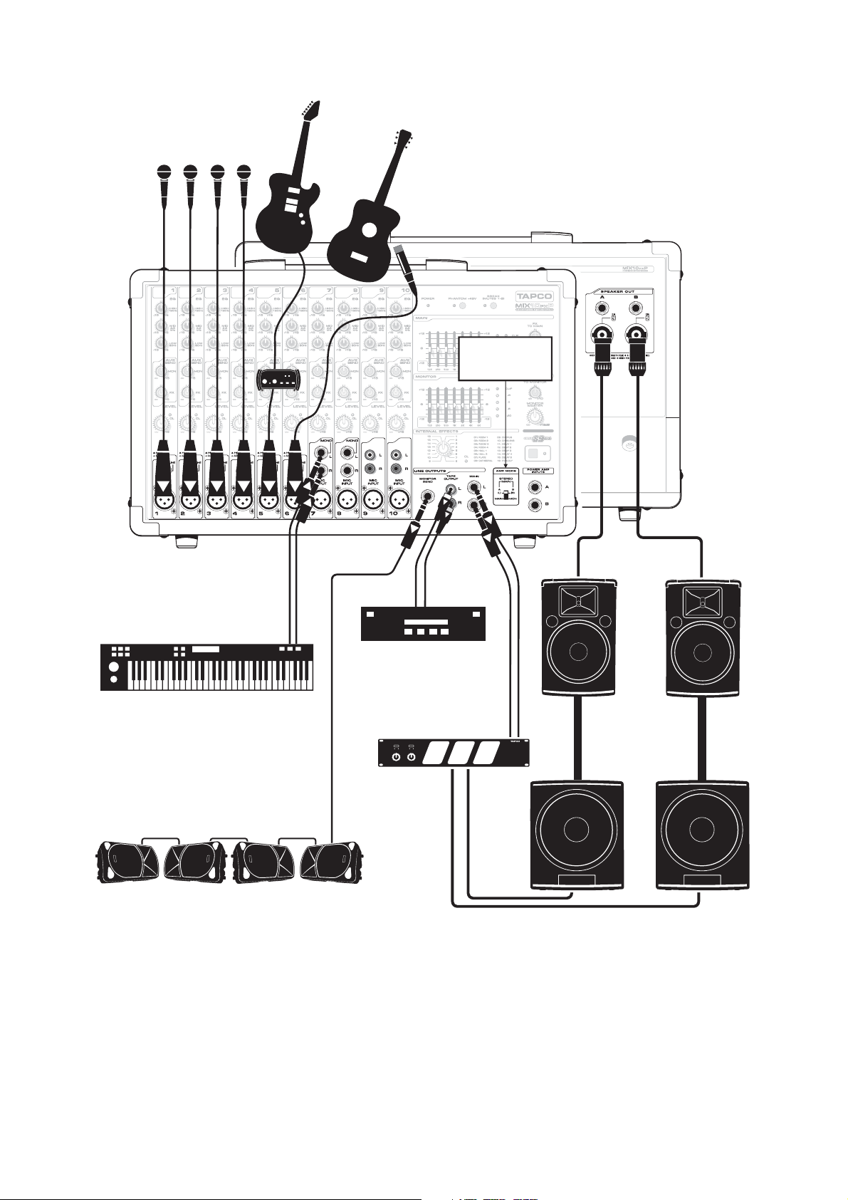
Club System
Microphones
DB-1A
DI Box
Electric
Guitar
Acoustic Guitar
and Mic
Amp Mode
switch set to
Stereo Main
6915 Passive Speakers
(plays stereo main mix)
Recorder
Keyboard
TAPCO Thump-15A Powered Speakers
used as Stage Monitors
This diagram shows microphones attached to channels 1 to 4, an electric guitar connected via a TAPCO DB-1A
DI box to channel 5, an acoustic guitar and mic to channel 6, and a keyboard attached to channel 7's stereo
inputs. A portable recorder is attached to the stereo tape outputs to record the performance.
TAPCO Thump TH15A powered speakers are connected to the monitor send, and are set up as stage monitors.
The aux mon controls of each channel allow you to create a stage monitor mix that is independent of the main
mix. Use the monitor graphic EQ to adjust the stage monitor EQ as desired.
TAPCO 6915 passive speakers are connected to the speaker-level power output of the powered mixer, and they
play the main stereo mix to your audience. The Series 69 EQ switch is engaged to enhance the performance
with these Series 69 speakers. TAPCO 6918s passive subwoofers are powered by a TAPCO J-2500 power amplifi er,
connected to the main line outputs to reinforce the low end in your system.
TAPCO J-2500
Power Amplifier
Po l e M ou nt
6918s Passive Subwoofers
6
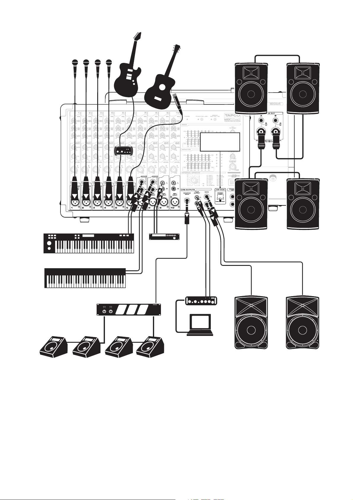
House of Worship
Microphones
DB-1A
DI Box
6912 Passive Speakers
Electric
Guitar
Acoustic Guitar
and Mic
Amp Mode
switch set to
Stereo Main
6912 Passive Speakers
CD/DVD
Player
Keyboard 1
Thump TH-15A
Powered Speakers
in Overflow Room
Keyboard 2
TAPCO J-2500
Power Amplifier
Stage Monitors
This diagram shows microphones attached to channels 1 to 4, an electric guitar connected via a TAPCO DB-1A
DI box to channel 5, a guitar mic to channel 6, keyboards attached to channel 7 and 8 stereo inputs, and a
CD/DVD player connected to channel 9's RCA inputs. A TAPCO Link.USB Digital Audio Interface is attached to
the stereo tape outputs to record the performance via USB onto a laptop.
A TAPCO J-2500 power amplifi er is connected to the line-level monitor send output, and powers four passive
stage monitors, two per side.
TAPCO 6912 passive speakers are connected to the speaker-level power output of the powered mixer, and
they play the main mix to your audience. There are two per side, connected in parallel, (minimum impedance
of 4 ohms per side).
TAPCO Thump TH15A powered speakers are connected to the main line-level outputs, and are set up to play
the main mix to an overfl ow room. Alternatively, you could run Thump TH18s powered subwoofers to reinforce
the low end in your main room.
TAPCO Link.USB
USB
Laptop
or Cry Room
7

Band Practice
Drum Kit Mics
Bass
Guitar
DI Box
Electric
Guitar
Guitar
Processor
Voca l
Microphones
Floor Monitors
(play monitor mix)
Amp Mode
switch set to
Main/Mon
CD Player
iPod Dock
6912 Passive Speakers
(plays mono main mix)
TAPCO Link.USB
Digital Audio Interface
USB
Pole Mount
Laptop
Thump TH-18s Powered Subwoofers
This diagram shows drum kit microphones connected to channels 1 to 4, a guitar connected via a TAPCO
DI box to channel 5, a guitar processor connected to the line input of channel 6, vocal mics connected to
channels 7 and 8, a CD player connected to channel 9's stereo RCA inputs, and an iPod dock connected to
channel 10's stereo RCA inputs. A TAPCO Link.USB Digital Audio Interface is attached to the stereo tape outputs
to record the performance via USB to a laptop.
The amp mode switch is set to main/mon. Passive stage monitors are connected to the speaker-level Ch.B
output, and play the monitor mix for your performers. TAPCO 6912 passive speakers are connected to the
speaker-level Ch.A output, and they play the main mono mix to your audience. TAPCO Thump TH18s powered
subwoofers are connected to the main line-level outputs, to reinforce the low end in your system.
8

Outdoor gig
Drum Kit Mics
DI Box
Gtr
Pro c.
Electric
Guitar
Guitar
Bass
Acoustic Guitar
and Mic
Voc al
Microphones
Amp Mode
switch set to
Stereo Main
6912 Passive Speakers
TAPCO J-1400
Power Amplifier
Recorder
Stage Monitors
This diagram shows drum kit microphones connected to channels 1 to 4, a guitar connected via a TAPCO DI
box to channel 5, a guitar processor connected to the line input of channel 6, an acoustic guitar with guitar
mic connected to channel 7, and vocal mics connected to channels 8, 9 and 10.
A TAPCO J-1400 power amplifi er is connected to the line-level monitor send output, and powers two passive
stage monitors. Monitor EQ can be adjusted with the monitor graphic EQ, and internal FX added.
A portable recorder is attached to the stereo tape RCA outputs to record the performance.
The amp mode switch is set to stereo mains. TAPCO 6912 passive speakers are connected to the speaker-level
outputs, and they play the main stereo mix to your audience. A TAPCO J-2500 power amplifi er is connected to
the main line-level outputs, and supplies speaker-level power to 6925 passive speakers to reinforce the volume
for outdoor events.
(play stereo main mix)
TAPCO J-2500
Power Amplifier
6925 Passive Speakers
(play stereo main mix)
9
 Loading...