

Page 1
USER’S GUIDE
™
™
MDW 2x2
Massenburg’s High Resolution Parametric EQ
Plug-in for Mackie Digital Mixers
®
™
Page 2
Iconography
This icon identifies a description of how to
perform an action with the mouse.
This icon identifies a description of how to
perform an action from the console.
This icon will lead you to some further
explanations of features and practical tips.
This icon marks information which is very
important, so please make sure you have a read.
“Mackie” and the “Running Man” figure are trademarks or
registered trademarks of Mackie Designs Inc. All other brand
names mentioned are trademarks or registered trademarks of
their respective holders, and are hereby acknowledged.
Part No. 820-254-00 Rev. A 03/2001
© 2001 Mackie Designs Inc. All Rights Reserved.
2
Massenburg EQ
Page 3

Contents
Introduction ----------------------------------------4
About Massenburg Design Works ---------------------------4
About the D8B UFX Card --------------------------------------4
About the MDW Equalizer ------------------------------------ 5
Let’s Get Started ---------------------------------- 6
Requirements----------------------------------------------------6
Authorizing the Plug-in----------------------------------------6
Unlock Procedure ----------------------------------------------- 7
Configuring the Plug-in --------------------------------------- 8
Using the MDW EQ Plug-in -------------------- 10
Stereo and Mono Front Panels ----------------------------- 10
Level Control --------------------------------------------------- 11
Frequency Control--------------------------------------------- 11
Q Control -------------------------------------------------------- 12
EQ Types ---------------------------------------------------------12
Saving, Loading, and Resetting a Preset ------------------ 13
Automation and Snapshot Control ---------- 16
FX Routing -----------------------------------------17
Note: Any future revisions of this guide will be available for
viewing and downloading from our website: www.mackie.com.
User’s Guide
3
Page 4

Introduction
Thank you for purchasing this EQ plug-in from Massenburg
Design Works. It is one of the exciting new family of 24-bit plugins for the D8B, specifically designed for the new Mackie
Universal Effects (UFX) card.
This high-resolution parametric EQ contains five discrete,
overlapping bands. Each band’s center frequency can be set
anywhere within the entire 16 Hz–21.5 kHz frequency range.
About Massenburg Design Works
Multiple Grammy and TEC Award-winner George Massenburg is
an internationally renowned producer, recording engineer, and
designer of audio equipment — and the creator of parametric
EQ! His stereo analog mastering equalizers have been dubbed
the best sounding EQs available anywhere at any price.
The goal of Massenburg Design Works is to create the best
sounding digital EQ ever designed. His first products are
specifically developed for the D8B, Sonic Solutions Mastering
System and the Sony Oxford console — obviously we are in good
company!
About the D8B UFX card
The UFX card provides robust processing power for computationheavy plug-ins. The UFX card is a 4-in/4-out architecture, which
means it can support four mono, two mono and one stereo, or
two stereo sends simultaneously. Up to four UFX cards can be
installed in the D8B, allowing up to sixteen simultaneous singlechannel effects, eight stereo plug-ins, or combinations thereof.
Note: Earlier D8Bs were fitted with 16 MB of memory. It is recommended that
you increase this to 32 MB (as fitted in newer D8Bs) if you install more than one
UFX card. Memory upgrade instructions are supplied with each UFX card.
4
Massenburg EQ
Page 5
About the MDW Equalizer
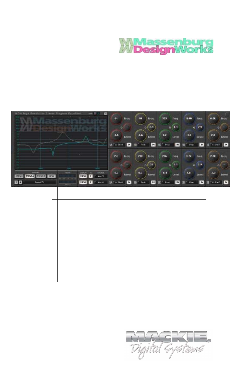
The MDW High-Resolution Parametric Equalizer plug-in
provides a five-band stereo/mono EQ to the D8B master stereo
bus, any individual channel or the surround buses. It operates at
double sample rates (96 kHz) to deliver excellent clarity and
response with superlative smoothness in the high-frequency
audio spectrum.
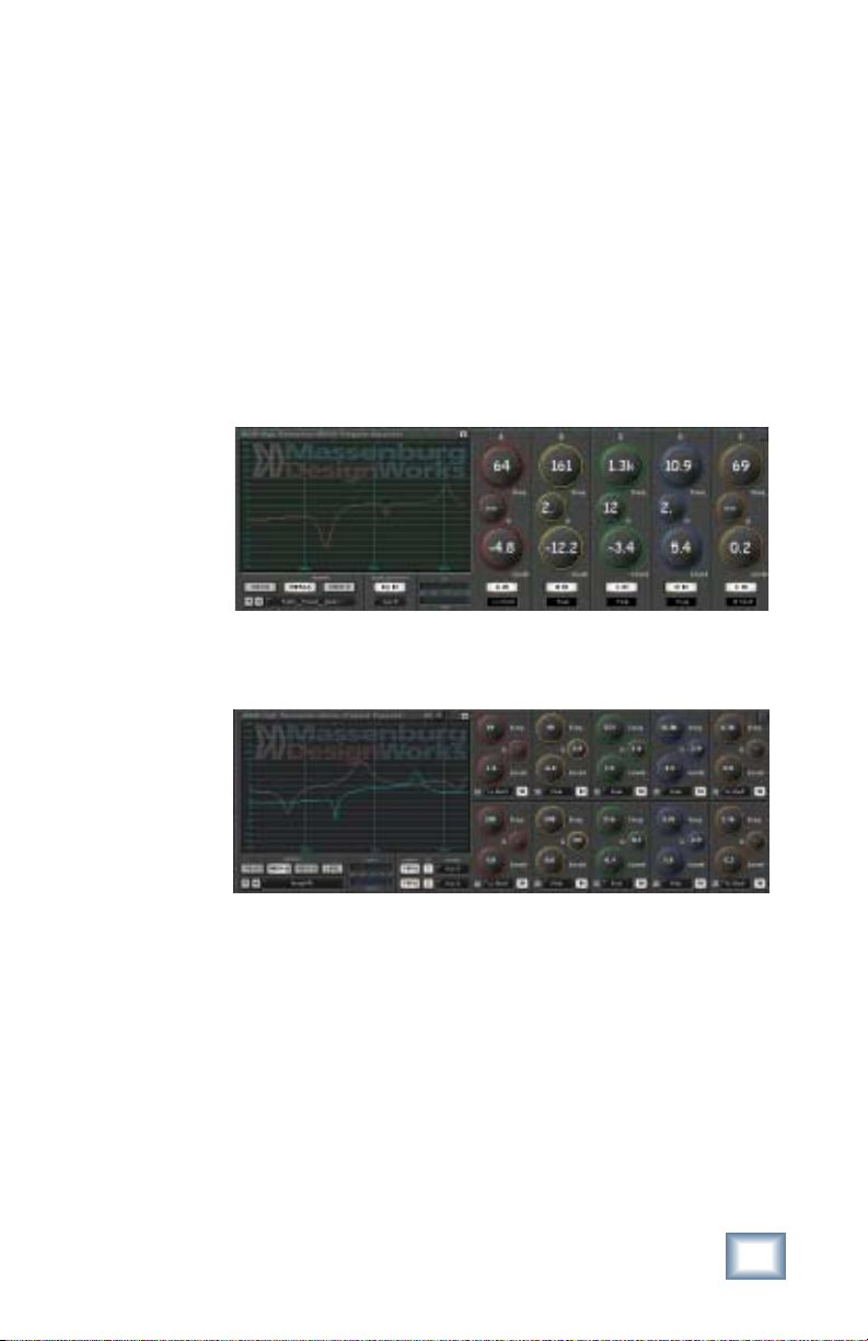
The plug-in can be loaded as MDW Stereo EQ or MDW Mono EQ.
MDW Mono EQ
MDW Stereo EQ
User’s Guide
5
Page 6
Let’s Get Started
Requirements
• One or more Mackie UFX cards
• Mackie Real Time OS 3.0 Software
• Plug-in Software
We will assume you have successfully installed a Mackie UFX
card and Mackie Real Time OS 3.0 software upgrade. If you have
encountered problems with the installation of hardware or
software please see their associated user guides or contact
Mackie support (www.mackie.com).
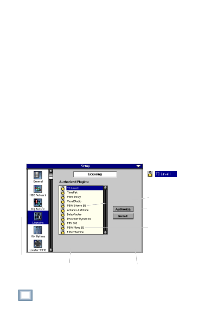
Authorizing the Plug-in
If you have D8B v 3.0 b186 or greater, the plug-in is already
installed on the D8B hard drive, however an authorized unlock
code must be entered to unlock the plug-in for normal operation.
Note that the MDW plug-in has two versions to be unlocked:
MDW Stereo EQ and MDW Mono EQ.
LICENSING
6
1234-5167-89D1
D8B Electronic Serial Number (ESN)
Massenburg EQ
An Unlocked
Plug-in
MDW Stereo EQ
AUTHORIZE
MDW Mono EQ
D8B SETUP screen’s
LICENSING window
Page 7
Unlock Procedure
1. Locate your D8B’s Electronic Serial Number (ESN). This
is displayed at the bottom of the Licensing window
which is accessed from the Setup screen. The 12 digit
ESN is made from numbers 0–9 and letters A–F. It is
unique to the D8B processor, and is not the serial
number label on the rear of the control surface or CPU
chassis.
2. You will also need your plug-in’s serial number which is
printed on each floppy disk label.
3. To obtain the unlock code, have the ESN and plug-in
serial number ready. Then you have two options:
• Log on to the Mackie plug-in authorization web page:
(http://www.mackie.com/d8bauthorize.htm)
or
• Telephone Mackie Tech Support at 800-258-6883.
4. When you have obtained an unlock code for the Mono
EQ, and one for the Stereo EQ, open the D8B Setup
window, and click Licensing.
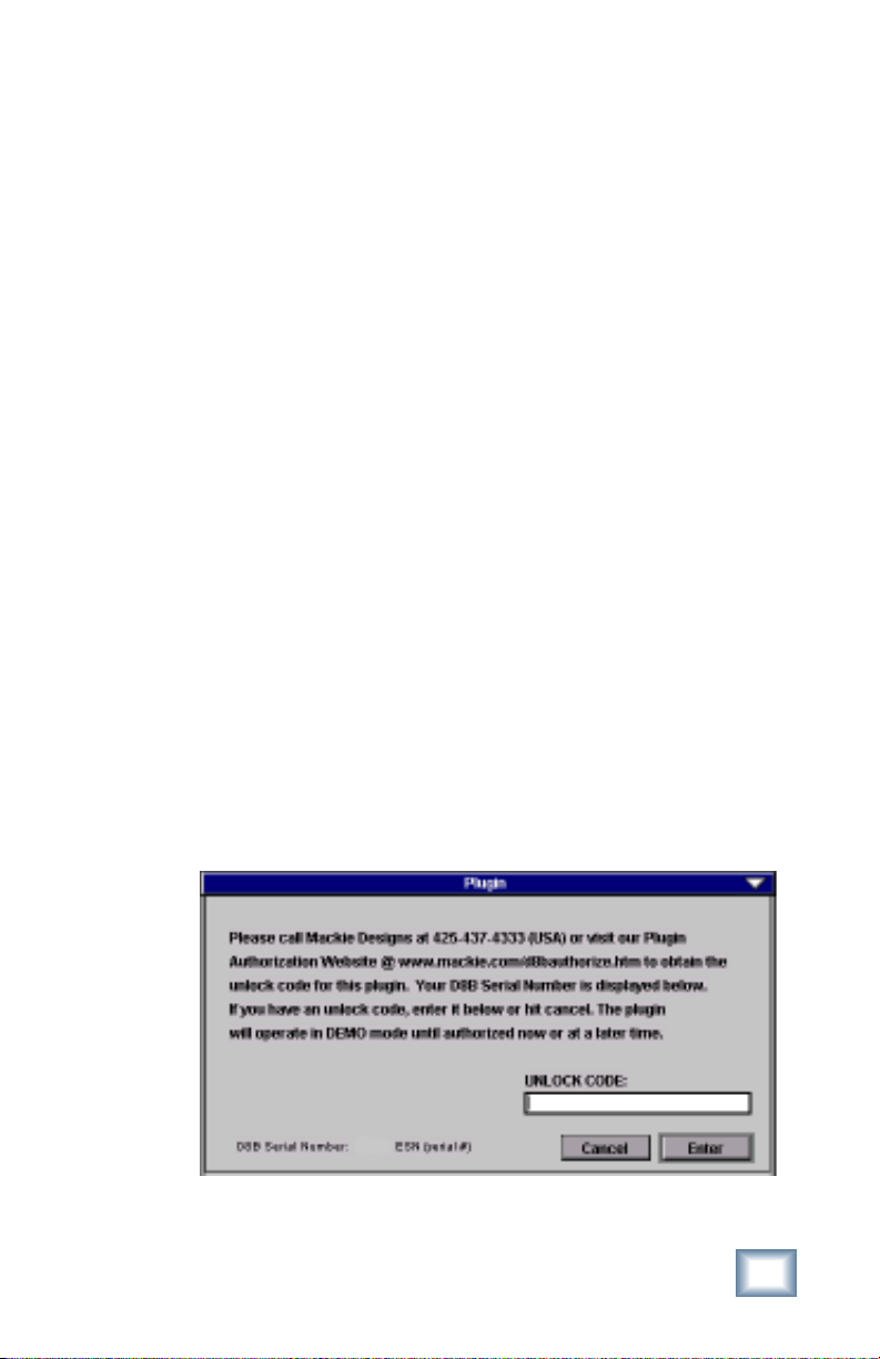
5. With your plug-in highlighted in the Licensing window,
click Authorize, and enter your unlock code in the
UNLOCK CODE box. Click Enter, and enjoy your newly
expanded console.
User’s Guide
7
Page 8
Configuring the Plug-in
After booting the D8B you must assign the MDW plug-in to a
UFX card. See FX Routing on page 17 for more details.
Assign the MDW Plug-in to a UFX card
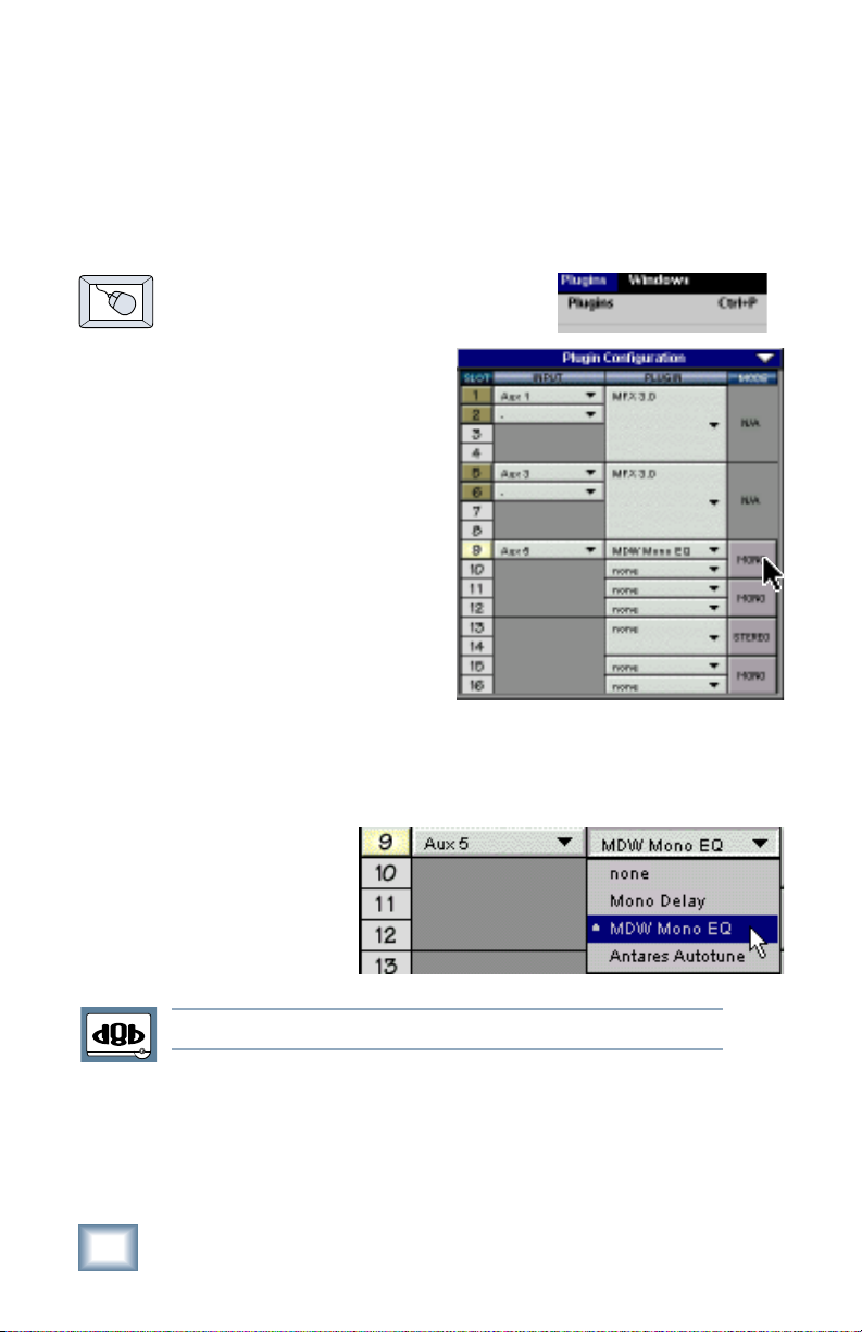
1. Click the Plugins menu and
select Plugins, or use
the keyboard shortcut
Ctrl+P.
2. In the Plugin
Configuration window,
locate the card slot
that contains the UFX
card you wish to
assign to.
3. In the Mode column,
click the Mono/Stereo
toggle button and set
it to Mono or Stereo.
4. In the Plugin column, select MDW Mono EQ or MDW
Stereo EQ from the drop-down menu.
Note:Note:
Note: A plug-in can also be loaded from the Setup section on the console.
Note:Note:
8
Massenburg EQ
Page 9

Assign an Input Source to the Plug-in
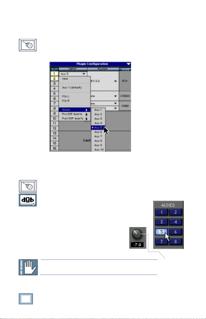
• Click the plug-in’s INPUT menu button to select an input
source. In the example below, we have chosen the Aux 5
Bus as the input to the plug-in installed in slot 5.
When a plug-in is fed from
an aux bus, its output
appears on the FX Return
channels (faders in the
EFFECTS bank). The return
channel is determined by
the slot number and
whether the effect output is
mono or stereo. For
example, a reverb with a
mono input and stereo
output that is installed in
Slot 5 has its outputs on FX
5 and FX 6. Note: The
default state for all FX
channels is MUTE. You
won’t hear the effect until
you unmute its FX return
channel(s).
A plug-in can also receive its input from a channel pre- or postDSP insert or the main stereo left and right bus. When a plug-in
is inserted “in line” in this manner, its output is routed directly
back into the channel. See FX Routing on page 17 for more
details.
Removing the Plug-in
1. Select none from the associated plug-in
drop-down assignment menu.
2. Click OK in the Alert dialog
box.
Note:Note:
Note: A plug-in can also be deleted
Note:Note:
from the Setup section on the console.
User’s Guide
9
Page 10

Using the MDW EQ Plug-in
MDW Mono Front Panel
Band
Graphical Display
(mouse active)
Menu
Preset Selection
& Display
Boundary
Markers
Input
Source
Memory
MDW Stereo Front Panel
Expand Button
(display controls)
Meter Display
EQ In/Out
(In/Out)
Edit Channel
toggle button
Five Bands of
Parametric EQs
EQ Type
Display
Hide Plug-in
Window Button
EQ In/Out
Buttons
Freq
Q
Level
Both right
and left
EQ curves
displayed
10
Link for
stereo
control
Global display
buttons for both
channels
Massenburg EQ
Global In/Out
buttons for both
EQ channels
EQ Type
EQ In/Out
Buttons
Page 11

Level Control
Each band’s gain can be adjusted within a range of +18 dB and
–18 dB. There are a few ways of changing the level:
• Click and drag up or down on the band’s Level control.
• Click and drag up or down in the graphical EQ display
within the band’s region (see note below).
• Right click and drag in the EQ display to change the
level and Q.
Frequency Control
Each band’s center frequency can be set between 16 Hz and
21.5 kHz.
• Click and drag up or down on the band’s Freq control.
• Click and drag horizontally in the MDW’s EQ display.
Note:Note:
Note: Each band can extend beyond it’s assigned region. If you have
Note:Note:
moved the band outside it’s region, you must still drag the mouse
cursor from within the band’s boundary markers in the display.
Frequency
Region for
Band A
Band
Boundary
Markers
You can change the level and center frequency by
dragging the mouse over the graph.
User’s Guide
EQ Band A
Frequency
Control
Q Control
Level
Control
11
Page 12

Q Control
This control adjusts the bandwidth of the
affected frequencies around the center
frequency. A higher Q value creates a tighter
bandwidth so fewer frequencies around the
center frequency are affected. A smaller Q
value creates a wider bandwidth so more
frequencies around the center frequency are
affected.
♦
To change the Q, click and drag up/down
or right/left on the band’s Q control.
♦
The Q and Level can also be adjusted by
right-clicking and dragging in the graphic display.
EQ Types
Each band (A thru D) has five EQ
types, except band E which has
two additional types. Under each
band you will notice a display
indicating the type of envelope
currently chosen.
Bands A
thru D
Q
12
♦
To change the EQ type,
click the EQ type display
and select from the dropdown list.
Massenburg EQ
Band E has two additional EQ
types, Low Pass 24 and High
Pass 24. They both use a
steeper cutoff slope than Low
Pass 12 and High Pass 12.
Page 13

Saving, Loading, and Resetting a Preset
EQ settings can be saved and
recalled from the hard drive. You can
save and load files from either
Memory A or Memory B.
To Save an EQ Preset:
1. Click and hold the Menu button.
2. Select Save User Preset to
overwrite the file currently
opened.
3. Select Save User Preset As to
save to a new file name. The
Save Preset File As dialog box
appears:
A new sub folder
can be easily created to help
organize custom
patches.
4. A default name for the patch is automatically displayed,
such as Preset#1. If you want to rename it, simply type
in the name you want, using up to 32 characters.
5. Select INTERNAL (default hard drive) or FLOPPY.
6. Click Save to complete the operation.
User’s Guide
13
Page 14

To Load an EQ Preset:
1. Click MEM A or MEM B to choose the memory location
from which to load the file.
2. Click and hold the MENU
button.
3. Select Load MDW Stereo (or
Mono) EQ to open a file. The Load
Preset File dialog box appears.
14
4. Click INTERNAL if the file is on the internal drive, or
click FLOPPY if the file is on a floppy disk.
5. Select the preset you want to load.
6. Click Open to load the selected preset.
You can also load a preset from
the Preset display, and toggle
through the presets using the
up and down arrows located to
the left.
Massenburg EQ
Page 15

To Reset The Preset:
Reset the plug-in also reverts to its default state.
1. Click and hold the MENU button.
2. Select Reset MDW Stereo (or
Mono) EQ.
To Cut Preset Settings:
1. Click and hold the MENU
button.
2. Select Cut MDW Stereo (or
Mono) EQ.
The current settings are temporarily
stored in the clipboard memory in case
you want to paste them to a new patch.
The plug-in also reverts to its default
state (it is reset).
To Copy Preset Settings:
1. Click and hold the MENU button.
2. Select Copy.
The current settings are temporarily stored in the clipboard
memory in case you want to paste them to a new patch.
To Paste Preset Settings:
1. Click and hold the MENU button.
2. Select Paste MDW Stereo (or Mono) EQ.
The current settings are replaced with the setting in the
clipboard memory.
User’s Guide
15
Page 16

Automation and Snapshot Control
Dynamic Real Time
To write automation on a loaded plug-in:
1. Engage AUTO TOUCH.
2. Engage ALL, disengage
BYPASS, and send
timecode to the console –
the POSITION readout will change to show TC is being
received.
3. Move a parameter or recall a patch (user or factory
preset).
Subsequent edits to any recorded automation moves may be
performed in the Mix Editor. Enable the channel view by clicking
the Channel View button, then choose the plug-in you wish to
view from the page drop-down
menu.This displays a list of
available channel and plug-in
automation tracks on a
parameter basis.
Note:Note:
Note: Parameters can be controlled from either the GUI plug-in graphic param-
Note:Note:
eters (using a mouse to modify the parameters) or via the VFD V-Pots and
SELECT buttons (with the plug-in parameters called up on the VFD readout).
On The Console
Dynamic Off-line
To write a snapshot on a loaded plug-in:
♦
Use the Event Automation Track, available under the
Window Menu as ‘Event Track’, to load plug-in user
(previously stored) or factory preset patches, at a
specific time during automation playback.
General Note:General Note:
General Note:
General Note:General Note:
Plug-in settings are recalled as part of a console Snapshot, but may also be recalled as Presets (patches). If you are recalling snapshots and presets, be aware
that one may override the other.
16
Massenburg EQ
Page 17

FX Routing
The Plug-in Configuration Window
Card Slot Column
Plug-in
display toggle
Input Channel
Assignment Dropdown Menu Button
Card A
Card B
Card C
Card D (no
card installed)
Input Source Assignment Column
Plug-in Assignment Column
Close Window
Stereo/Mono
Mode Column
Stereo/Mono
Toggle Button
User’s Guide
17
Page 18

Stereo Plug-in Routing
If the plug-in has a stereo input as well as stereo output,
typically it will be fed from two aux buses and returned to a pair
of FX return channels. In the diagram below, Aux 1 and Aux 2
feed the plug-in in stereo, and its output is returned to FX 1 and
FX 2.
If the plug-in has a stereo input, it is permissible to send the
same aux to both inputs.
FX Channels 1&2
(channels 49&50)
Stereo Input
(Aux 1 & 2)
Note:Note:
Note: When an FX Channel Assignment
Note:Note:
light is lit, the assigned plug-in is open and
visible on the main mixer screen.
Stereo Plug-in
18
Massenburg EQ
Page 19

Inserting a Plug-in into a Channel
A pre- or post-DSP channel insert can also be used as the input
source for a plug-in. When a channel insert point is selected, the
plug-in output returns to the channel. The FX return path is
disconnected, although the plug-in output is still displayed on
the FX return channel meter.
A plug-in channel insert assignment can be made from the
Plugin Configuration window, or from a drop-down menu from
the mixer screen.
Plug-in Configuration Window
Post-DSP Drop-down
Pre-DSP Drop-down
This assignment can also be made from the control surface and
VFD by holding in the desired channel’s SELECT button for two
seconds, then paging over to Plug Pre or Plug Post, selecting
the input source, then selecting the desired plug-in slot from the
follow-on menu.
User’s Guide
19
Page 20
Using an Aux Send with a Plug-in
♦
Click on the associated input menu button and select an
Aux input source. In the example below, we have chosen
the Aux 5 Bus.
Send the Input Signal to the Aux Bus
1. Send a signal to a D8B mixer input channel (MIC/LINE
or TAPE IN).
20
2. Assign the input channel V-Pot/GUI
Control Pot to an Aux Send. We have
chosen AUX 5 according to the example
above.
3. Use the AUX 5 control to
adjust the input level to the
plug-in.
Remember to Select an aux send before using the V-pot or GUI
Control Pot on the mixer input channel (MIC/LINE or TAPE IN).
Massenburg EQ
GUI Control
Pot Assigned
to AUX 5
Page 21

You will see the plug-in’s input meter become active as you raise
the mixer input channel’s aux send.
Set the plug-in input/output signal levels as you would with any
effect, so the meter reaches it’s upper-most range every so often
(always trust your ears first). This can be accomplished from the
console or GUI.
Pre-Fader and Post-Fader Auxiliary Sends
Normally, effect sends are post-fader, so the signal sent to the
effect follows the program level in the mix. Occasionally you
may wish to feed an effect from a pre-fader source so that the
signal level from the aux control is independent of the channel
fader position. Aux sends are selectable pre- or post-fader
globally (all Aux 1’s for instance) from the Mix Options screen in
the Setup window, or individually on a channel-by-channel basis
either from the channel strip or the Fat Channel.
In the channel strip, Alt-click on the Aux Send level
indicator to toggle between pre-and post-fader operation.
Post-fader is indicated by a red bar, pre-fader is indicated
by a yellow bar.
In the Fat Channel,
clicking on the small
indicators below the
Aux knobs toggles
between pre- and postfader operation. Yellow
indicates pre-fader,
post-fader is indicated
by the background
color.
Channel Strip
Fat Channel
User’s Guide
21
Page 22

The FX Return Channel
♦
Switch the D8B Bank Select to
EFFECTS (49-72) and bring up
faders one and two (channels 49 and
50). You will also see meter activity
associated with these channels.
FX Channels 1&2
(channels 49&50)
Stereo Plug-in
The Plug button
toggles between
Windows menu
buttons and FX
buttons (lower
left on the D8B
mixer screen).
22
Massenburg EQ
Plug-ins button opens the Patch
Configuration window (or
Ctrl+P
on the keyboard )
Here the Delay Factor plug-in is
selected for display.
Page 23

Complimentary Doodle Page
User’s Guide
23
Page 24

®
™
©2001 Mackie Designs Inc. and Massenburg Design Works
All Rights Reserved. Part No. 820-254-00 Rev. A 03/2001
 Loading...