

Mackie MDR 24, MDR 96, MDR 24/96 Operation Manual
MDR 24MDR 24
MDR 24/96
MDR 24MDR 24
Operation Guide
24 TRACK/24 BIT, DIGITAL AUDIO HARD DISK RECORDER
CAUTION AVIS
RISK OF ELECTRIC SHOCK
DO NOT OPEN
RISQUE DE CHOC ELECTRIQUE
NE PAS OUVRIR
CAUTION: TO REDUCE THE RISK OF ELECTRIC SHOCK
DO NOT REMOVE COVER (OR BACK)
NO USER-SERVICEABLE PARTS INSIDE
REFER SERVICING TO QUALIFIED PERSONNEL
ATTENTION: POUR EVITER LES RISQUES DE CHOC
ELECTRIQUE, NE PAS ENLEVER LE COUVERCLE. AUCUN
ENTRETIEN DE PIECES INTERIEURES PAR L’USAGER. CONFIER
L’ENTRETIEN AU PERSONNEL QUALIFIE.
AVIS: POUR EVITER LES RISQUES D’INCENDIE OU
D’ELECTROCUTION, N’EXPOSEZ PAS CET ARTICLE
MDR 24/96
A LA PLUIE OU A L’HUMIDITE
The lightning flash with arrowhead symbol within an equilateral
triangle is intended to alert the user to the presence of uninsulated
"dangerous voltage" within the product’s enclosure, that may be
of sufficient magnitude to constitute a risk of electric shock to persons.
Le symbole clair avec point de fl che l’int rieur d’un triangle
quilat ral est utilis pour alerter l’utilisateur de la pr sence
l’int rieur du coffret de "voltage dangereux" non isol d’ampleur
suffisante pour constituer un risque d’ l ctrocution.
The exclamation point within an equilateral triangle is intended to
alert the user of the presence of important operating and maintenance
(servicing) instructions in the literature accompanying the appliance.
Le point d’exclamation l’int rieur d’un triangle quilat ral est
employ pour alerter les utilisateurs de la pr sence d’instructions
importantes pour le fonctionnement et l’entretien (service) dans le
livret d’instruction accompagnant l’appareil.
Important Safety Instructions
1. Read instuctions — Read, understand and follow all safety and operating
instructions before using the MDR24/96.
2. Retain Instructions — Keep these safety and operating instructions for future
reference.
3. Heed Warnings — Follow all warnings on the MDR24/96 and in these
operating instructions.
4. Water and Moisture — Do not use the MDR24/96 near water – for
example, near a bathtub, kitchen sink, garden hose, incontinent poodle,
sweaty drummer, etc. – or when condensation has formed on the unit.
5. Heat and Ventilation — Locate the MDR24/96 away from heat sources such
as radiators, campfires, compost pits, heliarc welders, magma flows, etc. Do
not block MDR24/96 ventilation openings or install in spaces that prevent
adequate air circulation to the unit.
6. Power Sources — Connect the MDR24/96 only to a power source of the type
described in these operating instructions or as marked on the MDR24/96.
7. Power Cord Protection — Route power supply cords so that they are not likely
to be walked upon, tripped over, or abraded by items placed upon or against
them. Pay particular attention to cords at plugs, convenience receptacles, and
the point where they exit the MDR24/96.
8. Object and Liquid Entry — Do not drop objects or spill liquids into the
MDR24/96. Clean only with a damp cloth; do not clean with liquid or aerosol
cleaners.
9. Attachments — Use the MDR24/96 with only the accessories specified in
this manual.
10. Damage Requiring Service — The MDR24/96 should be serviced only by
qualified service personnel when:
A. The power supply cord or the plug has been damaged; or
B. Objects have fallen onto, or liquid has spilled into the unit; or
C. The unit has been exposed to rain or water; or
D. The unit does not appear to operate normally or exhibits a marked
change in performance; or
E. The unit has been dropped, or its chassis damaged.
11. Servicing — Do not attempt to service the MDR24/96. All servicing
should be referred to the Mackie Service Department.
12. Lightning — Unplug the MDR 24/96 during lightning storms or when
unused for long periods of time.
13. Grounding and Polarization — To prevent electric shock, do not use the
MDR24/96 polarized plug with an extension cord, receptacle or other
outlet unless the blades can be fully inserted to prevent blade exposure.
Do not defeat the MDR24/96 grounding by plugging into an ungrounded
receptacle or ground lift adapter.
This apparatus does not exceed the Class A/Class B (whichever is applicable)
limits for radio noise emissions from digital apparatus as set out in the radio
interference regulations of the Canadian Department of Communications.
ATTENTION — Le présent appareil numérique n’émet pas de bruits
radioélectriques dépassant las limites applicables aux appareils numériques de
class A/de class B (selon le cas) prescrites dans le réglement sur le brouillage
radioélectrique édicté par les ministere des communications du Canada.
FCC Information
NOTE: This equipment has been tested and found to comply
with the limits for a Class A digital devices, pursuant to Part 15
of the FCC Rules. These limits are designed to provide
reasonable protection against harmful interference when the
equipment is operated in a commercial installation. This
equipment generates, uses, and can radiate radio frequency
energy and, if not installed and used in accordance with the
instruction manual, may cause harmful interference to radio
communications. Operation of this equipment in a residential
area is likely to cause harmful interference in which case the
user will be required to correct the interference at his own
expense.
This product has been tested and complies with the
following standards and directives as set forth by the
European Union:
* EN 55022 Radiated and Conducted Emissions
* EN 61000-4-2 Electrostatic Discharge Immunity
* EN 61000-4-3 RF Electromagnetic Fields Immunity
* EN 61000-4-4 Electrical Fast Transient/Burst Immunity
* EN 60950/IEC 950 Electrical Safety Requirements
WARNING — To reduce the risk of fire or electric shock, do not expose this
appliance to rain or moisture.
WARNING — Before applying power to the MDR24/96, make sure that the
Voltage Selector switch next to the AC inlet jack on the rear panel is set to
the line voltage used in your region. Powering-on the MDR24/96 with
the Voltage Selector switch set incorrectly will cause an electrical and fire
hazard that may result in irreparable damage to the unit.
2
MDR 24/96

Contents
Operation Guide
Introduction ----------------------------5
Save your Box! -------------------------------- 5
How To Use This Guide --------------------- 5
Conventions ---------------------------------- 6
About “Tape” --------------------------------- 9
Overview -------------------------------------- 9
Setup and Configuration -------------10
Required Equipment ------------------------ 10
Installation------------------------------------ 10
I/O Cards and Cables ---------------------------- 11
Sync Card and Cables - Word Clock and
Digital Synchronization ------------------------- 13
Mackie Media (Optional) ----------------------- 15
Remote 24 / Remote 48 (Optional) ---------- 16
Footswitch (Optional) --------------------------- 16
Power-Up-------------------------------------- 16
Configuration--------------------------------- 17
I/O Cards------------------------------------------- 17
Synchronization------------------------------ 19
Synchronization Options ----------------------- 19
Sample Clock ---------------------------------- 19
Sample Rate ------------------------------------ 19
Bit-Depth --------------------------------------- 19
Time Code Chase ------------------------------ 19
Time Code Source ----------------------------- 20
Time Code Frame Rate ----------------------- 20
MMC Device ID -------------------------------- 20
Send MMC -------------------------------------- 21
Pre-roll Time ----------------------------------- 21
Pre-roll Enable --------------------------------- 21
Generate SMPTE/MTC ----------------------- 22
Time Code Offset ----------------------------- 22
Word Clock Divisors (88.2/96 kHz
operation only) -------------------------------- 22
Hookups ----------------------------------------23
Analog Hookup (AIO•8) ------------------------- 23
TDIF Hookup (DIO•8) ---------------------------- 25
ADAT Optical Hookup (DIO•8 or OPT•8) ---- 27
AES/EBU Hookup (PDI•8) ----------------------- 30
MDR24/96 Operation ----------------32
Project Management------------------------ 32
Creating Projects --------------------------------- 32
Opening Projects --------------------------------- 33
Saving Projects ------------------------------------ 33
Deleting Projects --------------------------------- 34
Purge Audio---------------------------------------- 34
Project Backup/Restore ------------------------ 35
Basic Transport Operations ----------------36
Play -------------------------------------------------- 36
Fast Wind------------------------------------------- 36
Stop ------------------------------------------------- 36
Record ---------------------------------------------- 36
Time Display ---------------------------------- 37
Locate Points and Looping----------------- 37
Recording ------------------------------------- 38
Virtual Tracks ------------------------------------- 38
Track Mutes ---------------------------------------- 39
Record Safe ---------------------------------------- 39
Auto Take ------------------------------------------ 40
Monitoring ----------------------------------------- 40
All Input----------------------------------------- 40
Auto Input -------------------------------------- 40
Metering and Setting Record Levels ---------- 41
Auto Punch ---------------------------------------- 42
Rehearse-------------------------------------------- 43
Footswitch Operation --------------------------- 43
Editing ----------------------------------------- 45
Delete Last ----------------------------------------- 45
Track Edit ------------------------------------------- 46
Cut --------------------------------------------------- 47
Join -------------------------------------------------- 47
Copy ------------------------------------------------- 48
Paste ------------------------------------------------ 48
Insert ------------------------------------------------ 49
Undo/Redo ---------------------------------------- 49
Editing Examples----------------------------- 51
Replacing a Multiple Track Chorus ----------- 51
Deleting a Section of Audio ------------------- 51
Making a Vocal Comp---------------------------- 52
Editing on a Computer -------------------------- 53
Disk Management ----------------------------53
Formatting Drives -------------------------------- 53
Verify Drive Performance ----------------------- 54
Mount/Refresh Drives -------------------------- 55
Operation Guide
3

Appendix A: Troubleshooting and Service----56
Appendix B: Specifications --------------------- 56
Appendix C: Upgrading the System Software - 57
Appendix D: Analog I/O Pinout ----------------58
MDR 24/96
Appendix E: Compatible Cables---------------- 59
Analog and Digital Multitrack Cables ----59
Horizon Music, Inc. ------------------------------- 59
Hosa Technology, Inc. ---------------------------- 59
Marshall Electronics ----------------------------- 60
Pro Co Sound, Inc. -------------------------------- 60
Other Cables---------------------------------- 60
Apogee Electronics Corporation -------------- 60
Canare ---------------------------------------------- 60
Whirlwind ------------------------------------------ 60
Appendix F: Networking (FTP) Setup --------- 61
Peer to Peer Networking------------------------ 61
Hardware Interconnection --------------------- 62
Network Configuration ------------------------- 62
System #1 Settings (MDR24/96)--------------- 63
System #2 Settings (second computer or
other Ethernet device) -------------------------- 64
Windows 95/98 ------------------------------- 64
Macintosh OS 9.2.1 ---------------------------- 65
FTP Client Configuration------------------------ 66
Troubleshooting ------------------------------- 66
Networking Glossary ------------------------- 66
Please write your serial number here for future
reference:
Purchased at:
Date Of Purchase:
Manual Part No. 0000107 Rev. B 10/02
© 2002 Mackie Designs Inc. All rights reserved
Printed in the U.S.A.
4
MDR 24/96

Introduction
Save your Box!
Uncle Jeff’s Bottom Ten Reasons to Save the Box:
10. You think boxes grow on trees?
9. It’s actually a time capsule, packed with a biological code that can’t be
decrypted until 2043.
8. Its festive graphics will cheer up those other boxes forgotten in your
attic.
7. Impress your friends: tape it up and pretend that you actually have two
MDR24/96s.
6. If you throw it away, bad people will know you have a studio in your
house.
5. Someday, when paper costs more than steel, it could net you a fortune.
4. The MDR24/96 itself only costs $47.95. The balance is what you paid for
the box.
3. Properly sealed, it can be used as a flotation device in the unlikely event
of a water landing.
2. It’s a great place to hide your old digital 8-track recorder.
1. If you collect ten MDR24/96 boxes, Greg will come over for dinner (this
offer does not apply to dealers or distributors).
Operation Guide
In the unlikely event that you should need to send the MDR24/96 back to Mackie
for service, please use the shipping box it came in. This box has been specially
designed to minimize damage to the MDR24/96 during shipping, so that it won’t
end up more broken than when you sent it.
How To Use This Guide
Welcome to the cutting edge of affordable multitrack recording and editing! We
know you’re feeling eager, but please take some time to read this Operation Guide
before you jump into your first MDR24/96 session. The first part of this guide
explains how to install and configure the various MDR24/96 I/O cards and connect
the MDR24/96 to an analog or digital console. The second part describes how to
start a session, operate the basic transport and monitoring controls, and explains
the terms and conventions used to name, store, and retrieve projects on disk. Then
the appendices contain information on troubleshooting and service, upgrading the
software, cabling, and networking.
Updated manuals and the latest software releases can be obtained from Mackie’s
website at:
www.mackie.com.
Operation Guide
5
MDR 24/96
Conventions
The MDR24/96 Quick Start Guide uses the following conventions to help you find
information quickly:
Text Conventions
a) File or folder names (example: C:\HDR Projects\Ode To Masters\Ode
To Masters.hdr)
b) Software or hardware controls (example: Punch)
c) Proper names of objects on front/rear panel (example: PLAY)
Icons
This icon identifies in-depth explanations of features and practical tips. Though
not required reading, they do offer some choice tidbits of knowledge that will
leave you wiser for the reading.
This icon identifies information that is critically important to the operation of the
MDR24/96. So for your own sake, please read these sections.
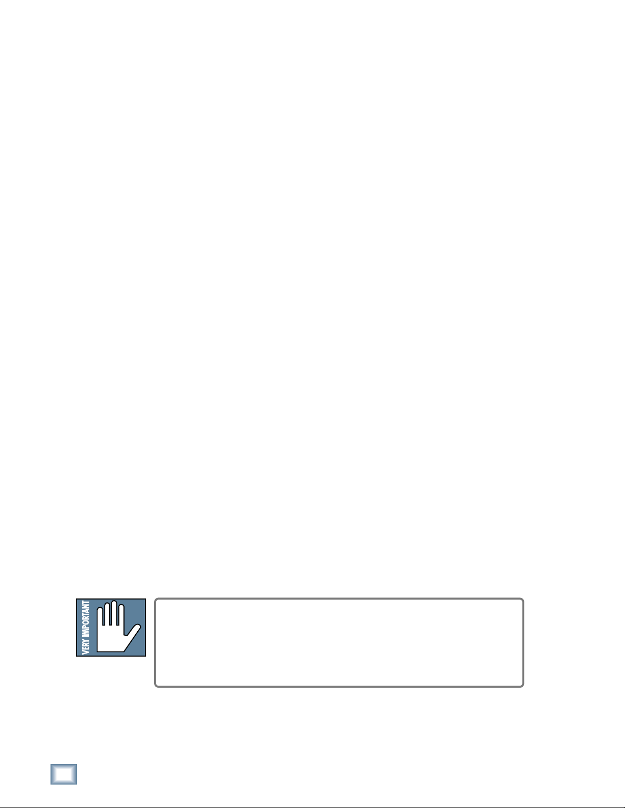
Front Panel User Interface Conventions
Most of the buttons on the front panel need no explanation (don’t worry, we’ll
explain them anyway). The display (LCD) and the buttons immediately below it
control the computer that’s at the heart of the MDR24/96. Once you understand
the functions, you’ll find them to be intuitive.
Originally we plopped all of the controls onto the MDR24/96 front panel and found
that after a while, it was entirely filled with buttons. So we decided to lose a few
along the way, and hide the ones that were used less frequently (as often as you
visited Aunt Sadie) somewhere under an LCD menu. To make up for missing
buttons and the need for a road map, we stuck in a few Go Here and Go There
buttons and here’s what we came up with:
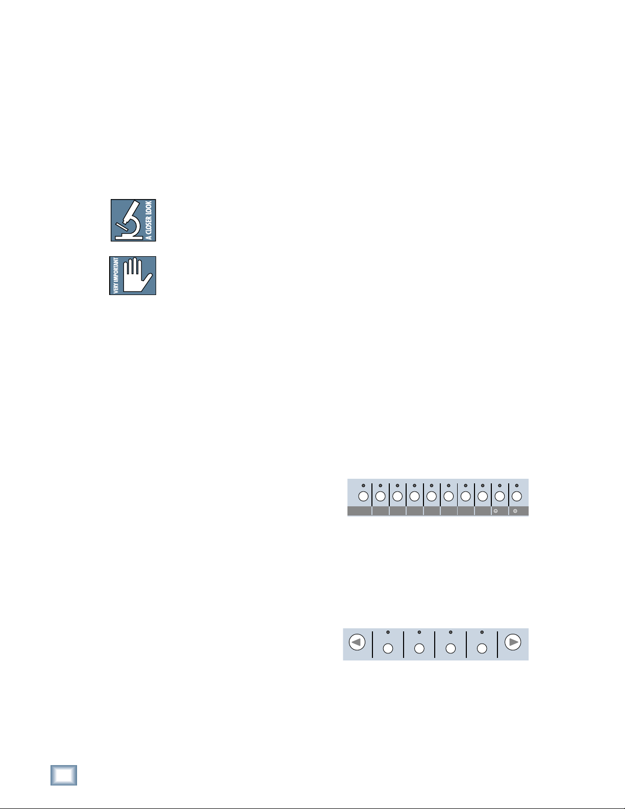
System Control Buttons
Most of the group of buttons
immediately above the transport
(“tape deck”) controls open menus in
the LCD. These are the entry points to
TRACK/
DELETE LAST PROJECT BACKUP DISK UTIL SYSTEM DIGI-I/O SYNC DEC INC
EDIT
the LCD menus and are called System
Control buttons.
Page Left and Page Right Buttons
The large < and > buttons are page navigators. If a menu consists of more than
one page, the top line on the 24 character by 4 line LCD readout will display a ←
or → in the upper left or upper right corner to indicate the direction in which you
may page to find more choices within
that menu.
SELECTSELECTSELECT
SELECT
Select Buttons
The four SELECT buttons under the
LCD are aligned under text describing the choices available within that menu.
Examples include Exit, confirmation (OK), increment or decrement a number,
scroll through choices, or advance through operational tiers (“follow the signs, you
won’t get lost”). Select buttons are soft buttons whose function changes depending
on the operation you’re performing.
6
MDR 24/96
Pairs of SELECT buttons with << >> displayed above them are used to select
MINUTESHOURS
SECONDS FR AMES
TICKS
BEATS
BARS
among choices or move a cursor ‘v’ through a text field. The (–)DEC and (+)INC
(decrement and increment) buttons scroll through choices in the active field.
Sometimes they duplicate the << >> buttons and, at other times, they interact,
where the << >> buttons select the character that will be changed by the DEC
and INC buttons.
Pressing the SELECT button labeled OK in the display performs the menu
operation in process. There’s usually a button labeled Cancel should you decide
not to complete an operation. Pressing any menu button will also back out without
performing the operation.
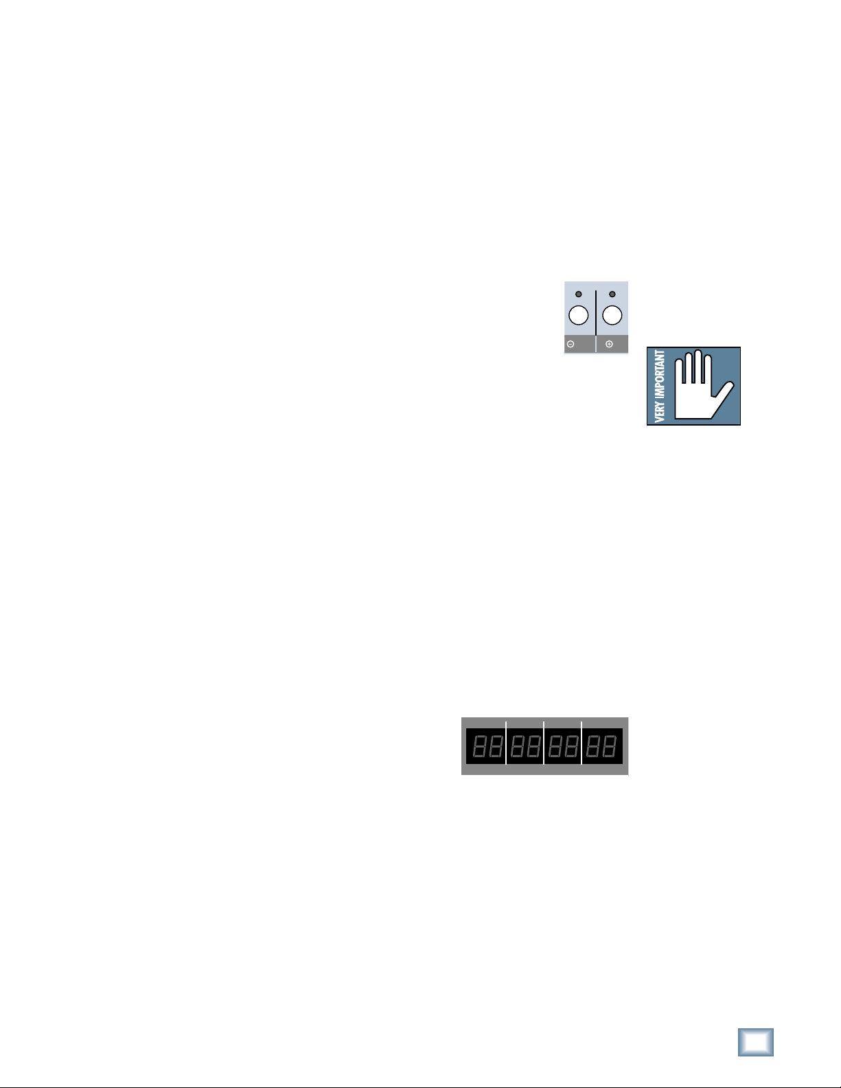
Front Panel Display and Controls
The (–)DEC and (+)INC (decrement and increment) buttons are
used to modify an alphabetical or numerical parameter displayed in
the LCD such as Project Name or Time Code Offset. If the red LEDs
above the buttons are glowing, they’re active. Generally you can tell
that a character can be edited with the (–)DEC and (+)INC buttons
if it’s sitting above a pair of << >> characters. The Select buttons
below the << >> characters move a ‘v’ cursor along numeric field, indicating
which character will be changed by pressing the (–)DEC and (+)INC buttons.
Any time you’re working in a menu, LED’s will illuminate above any button that
does something within that menu. Some operations, particularly those which could
be disastrous like deleting data that can’t be recovered, offer you a Cancel option,
allowing you to quit without changing anything.
Depending on the menu and how many layers it has, Exit or Cancel may bring you
back to a previous menu or all the way back to the top. You can also leave the
menu by pressing the button that got you there (its red LED will be lit to remind
you where you are), or by pressing the left < button when the ← symbol isn’t
displayed. You need not completely exit one menu before moving to another; just
press another menu button to jump into a new menu.
Transport Controls
Transport operating controls are described in detail in other sections of this
manual, so they won’t be repeated here. This section describes the front panel
displays and the setup and system function buttons located below the LCD.
Current Time Display
Current transport time is displayed in either
Hours:Minutes:Seconds:Frames (SMPTE time) or
musical score position in Bars:Beats:Ticks (BBT) if
you are working on a project brought over from an
HDR24/96. The project must be displaying BBT
when last saved on the HDR. The display cannot be changed from the MDR24/96
directly.
DEC INC
Note:Note:
Note: Whether or not a
Note:Note:
“Cancel” or “Exit”
prompt appears above a
SELECT button, it’s okay
to jump directly to one
of the other top level
menus without responding to a prompt. It’s a
quick “bail out” in case
you’ve discovered that
you’re in the wrong menu
for what you want to accomplish. Skipping an
OK, Cancel, or Exit
prompt will not harm or
hang the MDR24/96.
Operation Guide
In BBT mode, the front panel display only shows tick numbers when the transport
is stopped. When running, the Ticks field contains hyphens (- -). Leading spaces in
the Bars field are also filled with hyphens, as: - - 73:04:45. Bar numbers greater
than 999 are displayed as hyphens. However, the display still counts beats (01
through 04) while the transport is running.
Operation Guide
7
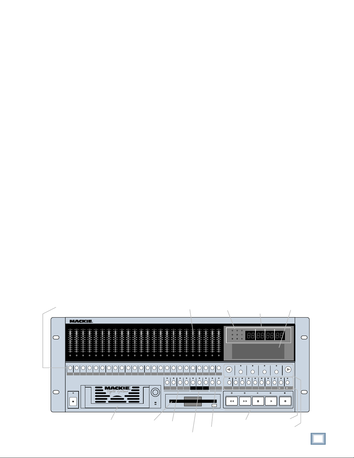
Status LEDs
The group of LEDs to the left of the time code display
indicates the state of several of the current setup options.
44.1k
48k
96k
MDR 24/96
• 44.1k, 48k and 96k LEDs indicate the selected
sample rate.
• VARI indicates that the sample rate is controlled by
an external word clock source or video sync signal.
• 16 BIT and 24 BIT indicate the selected word length.
• ERROR indicates a clock or synchronization error; for example, a word
clock frequency that is out of range.
TC indicates that the transport is receiving acceptable time code. This LED is only
active when the MDR24/96 is set to chase time code. The LED blinks when time
code is expected but is either not present or at the incorrect frame rate. When
everything is in order with time code synchronization, it will be on.
CLOCK indicates that a proper data clock signal is being received. It blinks if the
MDR24/96 is expecting an external clock and it’s not present. If all is well, when
Internal clock is selected, the CLOCK LED will be on.
VARI
ERROR
16 BIT
24 BIT
TC CLOCK
Front Panel Alphanumeric Display (LCD)
The front panel LCD, when not performing a setup or utility operation, is an
informative summary of the current project. A screen saver blanks the display after
ten minutes of display inactivity. To re-activate it, press one of the large < >
buttons or any menu button.
Project Information Display
The following information is displayed
on the MDR24/96 hardware front panel
display after boot-up and whenever any
front panel operation is exited.
PROJECT: [Name of the currently loaded project]
PLAYLIST: [The currently loaded playlist version]
DRIVE: [The disk drive containing the Project — Internal or External]
AVAIL: [The amount of recording time left on the disk]
The MDR 24/96 allows only one playlist. If a project is brought from an HDR24/96,
the last active playlist is used (you are not able to switch to other playlists from the
MDR24/96).
PROJECT: Project#1
PLAYLIST: Playlist 1
DRIVE: C:Internal
AVAIL: 01:35:00
Menu/Status Display
The LCD indicates menu choices and
displays status information when a
time-consuming operation, such as disk
formatting or file copy is in process.
The large < and > buttons scroll
through the menu horizontally if there
are more choices within the current level menu than can be displayed in the
available display area. An arrow ← or → at the top corner of the display indicates
that more choices are available, and in which direction to scroll in order to view them.
SYNC OPTIONS [1]->
Sample Time Code
Clock Rate Source Rate
8
MDR 24/96
About “Tape”
No, you’re not reading the wrong manual. Our goal was to build a hard disk recorder that is
comfortable for someone familiar with tape recording, but that doesn’t require you to get a
brain transplant from a computer geek to use. When familiar terms such as Tape Inputs,
Tape Returns, Transport, and the like are applied to the MDR24/96, they mean exactly
what you expect them to mean. Where the well-worn shoe fits, we continue to wear it.
Overview
By combining traditional multitrack tape recording features with the power and flexibility
of hard disk recording, the Mackie Designs MDR24/96 takes multitrack recording to a
level never before achieved by a product in its price range. In addition to the standard
battery of traditional tape-based features, the MDR24/96:
• Combines the familiarity of a multitrack tape machine with the security of nondestructive recording and non-degrading recording media.
• Records simultaneously on all 24 tracks at 44.1 or 48 kHz and on 12 tracks at
88.2 or 96 kHz. At 48 kHz the internal hard drive stores over 2200 track-minutes
of 24-bit audio (90 minutes of 24 full tracks). That’s more than six reels of 2-inch
tape at 30 inches per second! At 96 kHz the drive stores 1100 track-minutes of
24-bit audio (45 minutes of 24 full tracks).
• Has eight Virtual Takes per track, allowing you to record multiple passes without
having to change routing and bussing assignments or use additional tracks.
Operation Guide
• Iinterfaces with any analog or digital console. The MDR24/96 uses the same I/O
cards as the Mackie Digital 8•Bus console: the AIO•8 (24-bit analog A/D and
D/A), DIO•8 (TDIF/ADAT Optical), PDI•8 (AES/EBU), OPT•24 and low-cost
OPT•8 (ADAT Optical).
• Provides three convenient methods of backup: Mackie Media M•90, a removable
hard drive (also capable of 24-track recording and playback), Mackie Media
PROJECT, a removable drive using inexpensive, removable 2.2 GB ORB
cartridges; and data transfer to another computer through the MDR24/96’s
100 Base-T Ethernet port via the built-in FTP server.
• Offers two optional remote control devices — the compact Remote 24 for smaller
project studios, and the full-featured Remote 48 for controlling up to 48 tracks
on two MDR24/96 recorders.
Record Ready
24TRACK/24BIT DIGITAL AUDIO HARD DISK RECORDER
OL
OL
OL
OL
OL
2
2
2
4
4
4
7
7
7
10
10
10
15
15
15
20
20
20
25
25
25
30
30
30
35
35
35
40
40
40
50
50
50
REC REC REC REC REC REC REC REC REC REC REC
OL
2
2
2
4
4
4
7
7
7
10
10
10
15
15
15
20
20
20
25
25
25
30
30
30
35
35
35
40
40
40
50
50
50
Meter Display
OL
OL
OL
OL
OL
OL
OL
OL
OL
OL
OL
OL
OL
2
2
2
2
2
2
2
2
2
2
4
4
4
4
4
4
4
7
7
7
7
10
10
15
15
20
20
25
25
30
30
35
35
40
40
50
50
7
10
10
10
15
15
15
20
20
20
25
25
25
30
30
30
35
35
35
40
40
40
50
50
50
4
7
7
7
10
10
10
15
15
15
20
20
20
25
25
25
30
30
30
35
35
35
40
40
40
50
50
50
REC
REC REC REC REC REC REC REC REC REC REC REC REC
2
4
4
4
7
7
7
10
10
10
15
15
15
20
20
20
25
25
25
30
30
30
35
35
35
40
40
40
50
50
50
OL
2
2
2
4
4
4
7
7
7
10
10
10
15
15
15
20
20
20
25
25
25
30
30
30
35
35
35
40
40
40
50
50
50
2019181716151413121110987654321
OL
OL
2
2
4
4
7
7
10
10
15
15
20
20
25
25
30
30
35
35
40
40
50
50
21
Status Display
MDR 24/
OL
2
44.1k
4
7
10
15
20
25
30
35
40
50
242322212019181716151413121110987654321
242322
48k
VARI
16 BIT
ERROR
TC CLOCK
PROJECT: Little love
PLAYLIST: Playlist 1
DRIVE: C:Internal
AVAIL: 01:35:00
Current
Time Display
96k
24 BIT
HIGH RESOLUTION AUDIO
96
44.1/48/96K SAMPLE RATES
MINUTESHOURS
BARS
SELECTSELECTSELECT
SECONDS FR AMES
BEATS
TICKS
SELECT
LCD Display
POWER
ON
Media Tray Floppy Drive
LOC 2LOC 1 STORE
Locate &
Loop
Monitoring &
Record Safe
ALL
REC
LOOP
SAFE
1–2
AUTO
AUTO
INPUT
TAKE
INPUT
Auto Take &
Time code
Chase
T-CODE
TRACK/
DELETE LAST PROJECT BACKUP DISK UTIL SYSTEM DIGI-I/O SYNC DEC INC
CHASE
EDIT
REWIND
FAST FWD
Transport
PLAY
STOP
System Control
LCD Control
Operation Guide
RECORD
9
MDR 24/96
Setup and Configuration
This chapter explains how to set up and configure the MDR24/96 for use in your
studio. Two application examples show how to interface the MDR24/96 with
analog and digital recording consoles.
Required Equipment
Of course, there’s more to a studio than a recorder and some musicians. At a
minimum, you’ll need the following to make the MDR24/96 feel at home:
• Three Mackie 8-channel I/O (input/output) cards.
• A console with a minimum of 24 tape sends (buses or direct outputs) and
returns (line inputs or monitor returns). If your analog console has only 8
tape sends, use Y-cord splitters to send Tape Out 1 to MDR24/96 Inputs 1,
9 and 17; Tape Out 2 to MDR24/96 Inputs 2, 10, and 18, and so forth.
• Cables to connect the MDR24/96 to the console: 3 or 6 multi-channel
snakes or fiber optic cables, depending on your I/O setup.
• All the stuff that typically connects to a console: microphones,
instruments, outboard equipment, control room monitors, and so on.
Installation
This section describes how to install the I/O cards and how to connect the
MDR24/96 to your console. Before you begin, you should choose a location for
your MDR24/96 considering the following:
• If you’re not using the Remote 24 or Remote 48, position the front panel
within convenient reach of your normal recording/mixing position. Be
aware that although analog and AES/EBU cables can be fairly long, TDIF
and Remote 24/Remote 48 cables are limited to about 10 meters. ADAT
Optical cables can reach up to about 15 meters.
• The MDR24/96 requires a reliable AC power source with a good ground.
Do not use a ground lift adapter or plug the MDR24/96 into an
ungrounded receptacle. Remember, this is a computer. Using an
uninterruptible power supply (UPS) to power the MDR24/96 is a good idea
to avoid an unexpected shutdown and protect it from transient line voltages.
Warning!
Before applying power to the MDR24/96, make sure that the Voltage Selector
switch next to the AC inlet jack on the rear panel is set to the line voltage used
in your region. Powering-on the MDR24/96 with the Voltage Selector switch
set incorrectly can cause an electrical and fire hazard that may result in
irreparable damage to the unit.
10
MDR 24/96
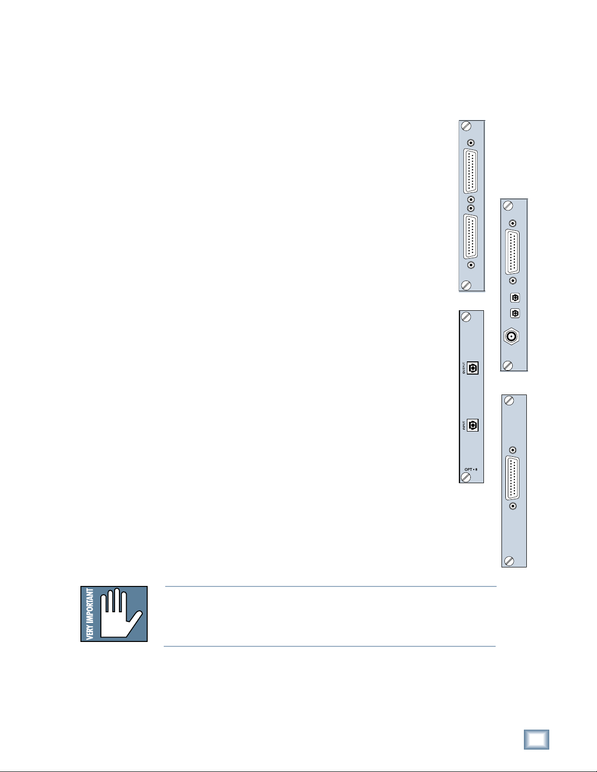
I/O Cards and Cables
While the MDR24/96 ships with AIO•8 cards already installed, three other flavors
of I/O cards are also available. All I/O cards can be mixed and matched in any
combination.
Operation Guide
AIO•8
• Each AIO•8 provides 8 analog line-level inputs and outputs on two 25-pin
D-subminiature (DB25) connectors. These connectors are pin-for-pin
compatible with the analog (not TDIF) DB25 connectors found on the
TASCAM DTRS recorders. DB25 cables that break out to XLR or 1/4" TRS
connectors for mating with your console are readily available.
DIO•8
• Each DIO•8 provides 8 digital inputs and outputs in two formats:
1. TASCAM Digital Interface (TDIF) provides 8 input and output channels
of digital audio on a single DB25 connector. It requires a TASCAM
PW-88D or equivalent TDIF-compatible cable.
2. ADAT Optical provides 8 channels of digital audio on fiber-optic cable.
Two optical cables are required for each card, one for inputs, the other
for outputs. Both cables must connect to the same device, creating a
closed loop.
3. The DIO•8 also provides a TDIF word clock sync output for use with
older TASCAM equipment.
OPT• 8
• The OPT•8 is a low-cost, ADAT Optical-only version of the DIO•8 card.
The previous ADAT information also applies to this card.
PDI• 8
• Each PDI•8 carries four stereo pairs (eight channels) of digital input and
output on a single DB25 connector. This card supports the AES/EBU
(IEC-958 Type 1) digital interfacing standard carrying two channels of
digital audio on a single balanced cable. The PDI•8 can also be configured
for the consumer (IEC-958 Type 2, or S/PDIF) data format if required.
DB25 cables that break out to XLR connectors, and double-ended DB25 to
DB25 AES/EBU cables for mating with your console, are readily available.
AIO•8
ANALOG I/O
OPT•8
INPUT OUTPUT
DIO•8
APOGEE
DIGITAL I/O
ADAT OPTICAL
PDI•8
TDIF
IN OUT
SYNC
AES/EBU I/O
The PDI•8 is the only Mackie I/O card that currently supports 88.2 or 96
kHz operation. At these sample rates, the PDI•8 card runs in “doublewide” (dual-wire) mode. In double-wide mode, the PDI•8 carries four mono
channels of digital I/O by transmitting two consecutive 88.2/96k samples
of the same channel on a single conductor.
Note: Different manufacturers use different wiring standards for DB25 interface cables (both analog and digital) that otherwise look the same. Make
sure the cable you are using is the correct one. See Appendix E for a list of
compatible MDR24/96 I/O card cables.
Operation Guide
PDI• 8
11
 Loading...