

Mackie MDR24/96 Operation Manual
MDR 24MDR 24
MDR 24/96
MDR 24MDR 24
Operation Guide
24 TRACK/24 BIT, DIGITAL AUDIO HARD DISK RECORDER
CAUTION AVIS
RISK OF ELECTRIC SHOCK
DO NOT OPEN
RISQUE DE CHOC ELECTRIQUE
NE PAS OUVRIR
CAUTION: TO REDUCE THE RISK OF ELECTRIC SHOCK
DO NOT REMOVE COVER (OR BACK)
NO USER-SERVICEABLE PARTS INSIDE
REFER SERVICING TO QUALIFIED PERSONNEL
ATTENTION: POUR EVITER LES RISQUES DE CHOC
ELECTRIQUE, NE PAS ENLEVER LE COUVERCLE. AUCUN
ENTRETIEN DE PIECES INTERIEURES PAR L’USAGER. CONFIER
L’ENTRETIEN AU PERSONNEL QUALIFIE.
AVIS: POUR EVITER LES RISQUES D’INCENDIE OU
D’ELECTROCUTION, N’EXPOSEZ PAS CET ARTICLE
MDR 24/96
A LA PLUIE OU A L’HUMIDITE
The lightning flash with arrowhead symbol within an equilateral
triangle is intended to alert the user to the presence of uninsulated
"dangerous voltage" within the product’s enclosure, that may be
of sufficient magnitude to constitute a risk of electric shock to persons.
Le symbole clair avec point de fl che l’int rieur d’un triangle
quilat ral est utilis pour alerter l’utilisateur de la pr sence
l’int rieur du coffret de "voltage dangereux" non isol d’ampleur
suffisante pour constituer un risque d’ l ctrocution.
The exclamation point within an equilateral triangle is intended to
alert the user of the presence of important operating and maintenance
(servicing) instructions in the literature accompanying the appliance.
Le point d’exclamation l’int rieur d’un triangle quilat ral est
employ pour alerter les utilisateurs de la pr sence d’instructions
importantes pour le fonctionnement et l’entretien (service) dans le
livret d’instruction accompagnant l’appareil.
Important Safety Instructions
1. Read instuctions — Read, understand and follow all safety and operating
instructions before using the MDR24/96.
2. Retain Instructions — Keep these safety and operating instructions for future
reference.
3. Heed Warnings — Follow all warnings on the MDR24/96 and in these
operating instructions.
4. Water and Moisture — Do not use the MDR24/96 near water – for
example, near a bathtub, kitchen sink, garden hose, incontinent poodle,
sweaty drummer, etc. – or when condensation has formed on the unit.
5. Heat and Ventilation — Locate the MDR24/96 away from heat sources such
as radiators, campfires, compost pits, heliarc welders, magma flows, etc. Do
not block MDR24/96 ventilation openings or install in spaces that prevent
adequate air circulation to the unit.
6. Power Sources — Connect the MDR24/96 only to a power source of the type
described in these operating instructions or as marked on the MDR24/96.
7. Power Cord Protection — Route power supply cords so that they are not likely
to be walked upon, tripped over, or abraded by items placed upon or against
them. Pay particular attention to cords at plugs, convenience receptacles, and
the point where they exit the MDR24/96.
8. Object and Liquid Entry — Do not drop objects or spill liquids into the
MDR24/96. Clean only with a damp cloth; do not clean with liquid or aerosol
cleaners.
9. Attachments — Use the MDR24/96 with only the accessories specified in
this manual.
10. Damage Requiring Service — The MDR24/96 should be serviced only by
qualified service personnel when:
A. The power supply cord or the plug has been damaged; or
B. Objects have fallen onto, or liquid has spilled into the unit; or
C. The unit has been exposed to rain or water; or
D. The unit does not appear to operate normally or exhibits a marked
change in performance; or
E. The unit has been dropped, or its chassis damaged.
11. Servicing — Do not attempt to service the MDR24/96. All servicing
should be referred to the Mackie Service Department.
12. Lightning — Unplug the MDR 24/96 during lightning storms or when
unused for long periods of time.
13. Grounding and Polarization — To prevent electric shock, do not use the
MDR24/96 polarized plug with an extension cord, receptacle or other
outlet unless the blades can be fully inserted to prevent blade exposure.
Do not defeat the MDR24/96 grounding by plugging into an ungrounded
receptacle or ground lift adapter.
This apparatus does not exceed the Class A/Class B (whichever is applicable)
limits for radio noise emissions from digital apparatus as set out in the radio
interference regulations of the Canadian Department of Communications.
ATTENTION — Le présent appareil numérique n’émet pas de bruits
radioélectriques dépassant las limites applicables aux appareils numériques de
class A/de class B (selon le cas) prescrites dans le réglement sur le brouillage
radioélectrique édicté par les ministere des communications du Canada.
FCC Information
NOTE: This equipment has been tested and found to comply
with the limits for a Class A digital devices, pursuant to Part 15
of the FCC Rules. These limits are designed to provide
reasonable protection against harmful interference when the
equipment is operated in a commercial installation. This
equipment generates, uses, and can radiate radio frequency
energy and, if not installed and used in accordance with the
instruction manual, may cause harmful interference to radio
communications. Operation of this equipment in a residential
area is likely to cause harmful interference in which case the
user will be required to correct the interference at his own
expense.
This product has been tested and complies with the
following standards and directives as set forth by the
European Union:
* EN 55022 Radiated and Conducted Emissions
* EN 61000-4-2 Electrostatic Discharge Immunity
* EN 61000-4-3 RF Electromagnetic Fields Immunity
* EN 61000-4-4 Electrical Fast Transient/Burst Immunity
* EN 60950/IEC 950 Electrical Safety Requirements
WARNING — To reduce the risk of fire or electric shock, do not expose this
appliance to rain or moisture.
WARNING — Before applying power to the MDR24/96, make sure that the
Voltage Selector switch next to the AC inlet jack on the rear panel is set to
the line voltage used in your region. Powering-on the MDR24/96 with
the Voltage Selector switch set incorrectly will cause an electrical and fire
hazard that may result in irreparable damage to the unit.
2
MDR 24/96

Contents
Operation Guide
Introduction ----------------------------5
Save your Box! -------------------------------- 5
How To Use This Guide --------------------- 5
Conventions ---------------------------------- 6
About “Tape” --------------------------------- 9
Overview -------------------------------------- 9
Setup and Configuration -------------10
Required Equipment ------------------------ 10
Installation------------------------------------ 10
I/O Cards and Cables ---------------------------- 11
Sync Card and Cables - Word Clock and
Digital Synchronization ------------------------- 13
Mackie Media (Optional) ----------------------- 15
Remote 24 / Remote 48 (Optional) ---------- 16
Footswitch (Optional) --------------------------- 16
Power-Up-------------------------------------- 16
Configuration--------------------------------- 17
I/O Cards------------------------------------------- 17
Synchronization------------------------------ 19
Synchronization Options ----------------------- 19
Sample Clock ---------------------------------- 19
Sample Rate ------------------------------------ 19
Bit-Depth --------------------------------------- 19
Time Code Chase ------------------------------ 19
Time Code Source ----------------------------- 20
Time Code Frame Rate ----------------------- 20
MMC Device ID -------------------------------- 20
Send MMC -------------------------------------- 21
Pre-roll Time ----------------------------------- 21
Pre-roll Enable --------------------------------- 21
Generate SMPTE/MTC ----------------------- 22
Time Code Offset ----------------------------- 22
Word Clock Divisors (88.2/96 kHz
operation only) -------------------------------- 22
Hookups ----------------------------------------23
Analog Hookup (AIO•8) ------------------------- 23
TDIF Hookup (DIO•8) ---------------------------- 25
ADAT Optical Hookup (DIO•8 or OPT•8) ---- 27
AES/EBU Hookup (PDI•8) ----------------------- 30
MDR24/96 Operation ----------------32
Project Management------------------------ 32
Creating Projects --------------------------------- 32
Opening Projects --------------------------------- 33
Saving Projects ------------------------------------ 33
Deleting Projects --------------------------------- 34
Purge Audio---------------------------------------- 34
Project Backup/Restore ------------------------ 35
Basic Transport Operations ----------------36
Play -------------------------------------------------- 36
Fast Wind------------------------------------------- 36
Stop ------------------------------------------------- 36
Record ---------------------------------------------- 36
Time Display ---------------------------------- 37
Locate Points and Looping----------------- 37
Recording ------------------------------------- 38
Virtual Tracks ------------------------------------- 38
Track Mutes ---------------------------------------- 39
Record Safe ---------------------------------------- 39
Auto Take ------------------------------------------ 40
Monitoring ----------------------------------------- 40
All Input----------------------------------------- 40
Auto Input -------------------------------------- 40
Metering and Setting Record Levels ---------- 41
Auto Punch ---------------------------------------- 42
Rehearse-------------------------------------------- 43
Footswitch Operation --------------------------- 43
Editing ----------------------------------------- 45
Delete Last ----------------------------------------- 45
Track Edit ------------------------------------------- 46
Cut --------------------------------------------------- 47
Join -------------------------------------------------- 47
Copy ------------------------------------------------- 48
Paste ------------------------------------------------ 48
Insert ------------------------------------------------ 49
Undo/Redo ---------------------------------------- 49
Editing Examples----------------------------- 51
Replacing a Multiple Track Chorus ----------- 51
Deleting a Section of Audio ------------------- 51
Making a Vocal Comp---------------------------- 52
Editing on a Computer -------------------------- 53
Disk Management ----------------------------53
Formatting Drives -------------------------------- 53
Verify Drive Performance ----------------------- 54
Mount/Refresh Drives -------------------------- 55
Operation Guide
3

Appendix A: Troubleshooting and Service----56
Appendix B: Specifications --------------------- 56
Appendix C: Upgrading the System Software - 57
Appendix D: Analog I/O Pinout ----------------58
MDR 24/96
Appendix E: Compatible Cables---------------- 59
Analog and Digital Multitrack Cables ----59
Horizon Music, Inc. ------------------------------- 59
Hosa Technology, Inc. ---------------------------- 59
Marshall Electronics ----------------------------- 60
Pro Co Sound, Inc. -------------------------------- 60
Other Cables---------------------------------- 60
Apogee Electronics Corporation -------------- 60
Canare ---------------------------------------------- 60
Whirlwind ------------------------------------------ 60
Appendix F: Networking (FTP) Setup --------- 61
Peer to Peer Networking------------------------ 61
Hardware Interconnection --------------------- 62
Network Configuration ------------------------- 62
System #1 Settings (MDR24/96)--------------- 63
System #2 Settings (second computer or
other Ethernet device) -------------------------- 64
Windows 95/98 ------------------------------- 64
Macintosh OS 9.2.1 ---------------------------- 65
FTP Client Configuration------------------------ 66
Troubleshooting ------------------------------- 66
Networking Glossary ------------------------- 66
Please write your serial number here for future
reference:
Purchased at:
Date Of Purchase:
Manual Part No. 0000107 Rev. B 10/02
© 2002 Mackie Designs Inc. All rights reserved
Printed in the U.S.A.
4
MDR 24/96

Introduction
Save your Box!
Uncle Jeff’s Bottom Ten Reasons to Save the Box:
10. You think boxes grow on trees?
9. It’s actually a time capsule, packed with a biological code that can’t be
decrypted until 2043.
8. Its festive graphics will cheer up those other boxes forgotten in your
attic.
7. Impress your friends: tape it up and pretend that you actually have two
MDR24/96s.
6. If you throw it away, bad people will know you have a studio in your
house.
5. Someday, when paper costs more than steel, it could net you a fortune.
4. The MDR24/96 itself only costs $47.95. The balance is what you paid for
the box.
3. Properly sealed, it can be used as a flotation device in the unlikely event
of a water landing.
2. It’s a great place to hide your old digital 8-track recorder.
1. If you collect ten MDR24/96 boxes, Greg will come over for dinner (this
offer does not apply to dealers or distributors).
Operation Guide
In the unlikely event that you should need to send the MDR24/96 back to Mackie
for service, please use the shipping box it came in. This box has been specially
designed to minimize damage to the MDR24/96 during shipping, so that it won’t
end up more broken than when you sent it.
How To Use This Guide
Welcome to the cutting edge of affordable multitrack recording and editing! We
know you’re feeling eager, but please take some time to read this Operation Guide
before you jump into your first MDR24/96 session. The first part of this guide
explains how to install and configure the various MDR24/96 I/O cards and connect
the MDR24/96 to an analog or digital console. The second part describes how to
start a session, operate the basic transport and monitoring controls, and explains
the terms and conventions used to name, store, and retrieve projects on disk. Then
the appendices contain information on troubleshooting and service, upgrading the
software, cabling, and networking.
Updated manuals and the latest software releases can be obtained from Mackie’s
website at:
www.mackie.com.
Operation Guide
5
MDR 24/96
Conventions
The MDR24/96 Quick Start Guide uses the following conventions to help you find
information quickly:
Text Conventions
a) File or folder names (example: C:\HDR Projects\Ode To Masters\Ode
To Masters.hdr)
b) Software or hardware controls (example: Punch)
c) Proper names of objects on front/rear panel (example: PLAY)
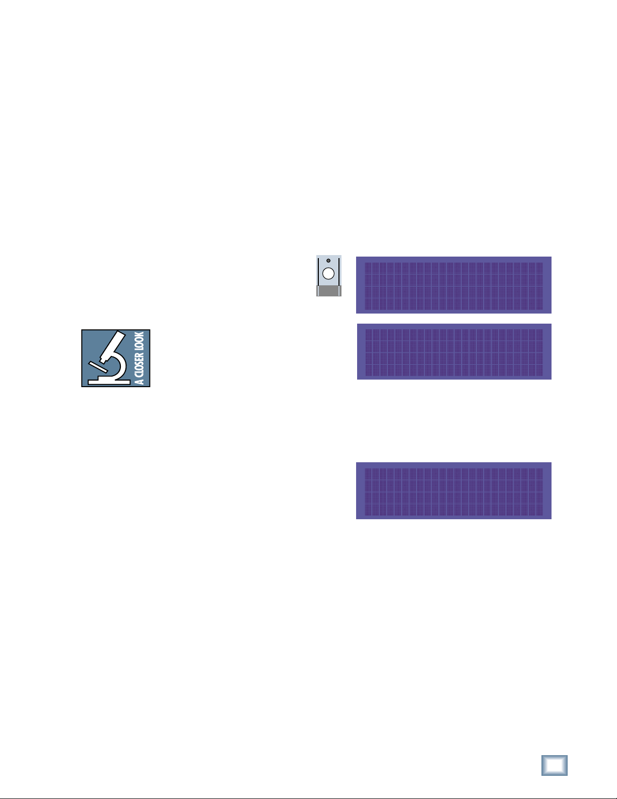
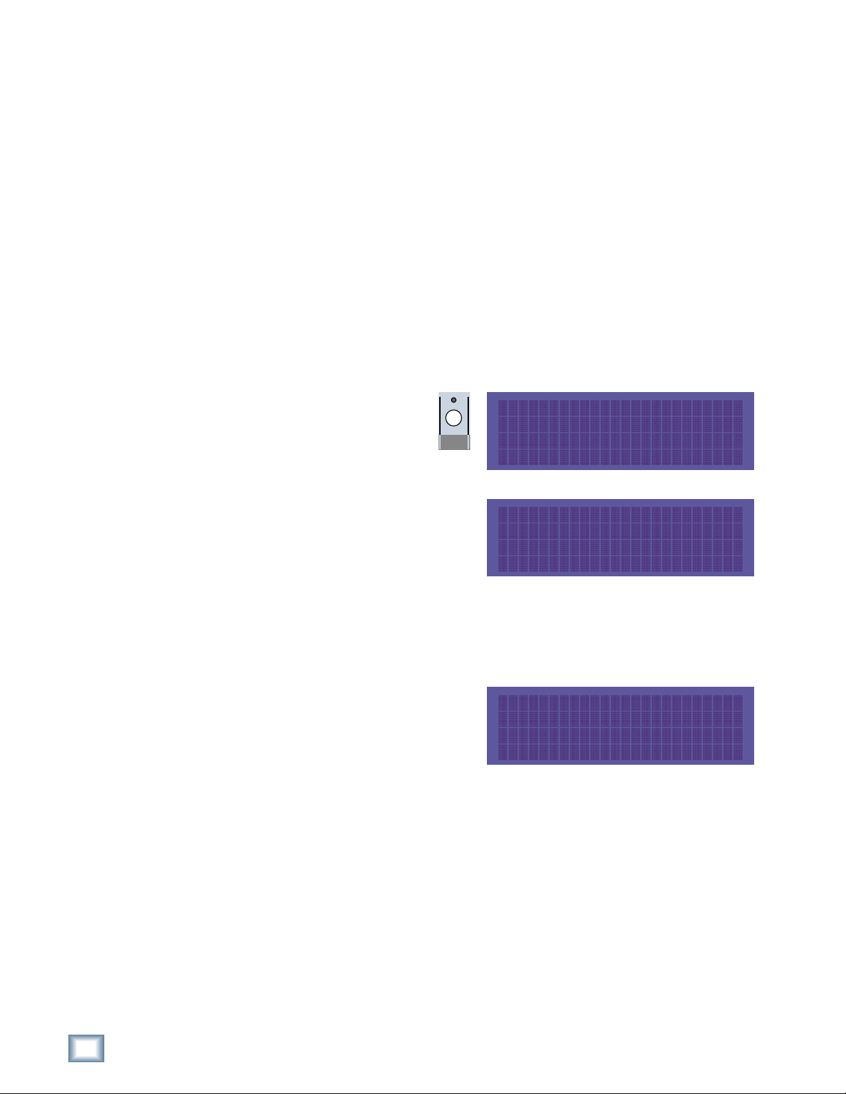
Icons
This icon identifies in-depth explanations of features and practical tips. Though
not required reading, they do offer some choice tidbits of knowledge that will
leave you wiser for the reading.
This icon identifies information that is critically important to the operation of the
MDR24/96. So for your own sake, please read these sections.
Front Panel User Interface Conventions
Most of the buttons on the front panel need no explanation (don’t worry, we’ll
explain them anyway). The display (LCD) and the buttons immediately below it
control the computer that’s at the heart of the MDR24/96. Once you understand
the functions, you’ll find them to be intuitive.
Originally we plopped all of the controls onto the MDR24/96 front panel and found
that after a while, it was entirely filled with buttons. So we decided to lose a few
along the way, and hide the ones that were used less frequently (as often as you
visited Aunt Sadie) somewhere under an LCD menu. To make up for missing
buttons and the need for a road map, we stuck in a few Go Here and Go There
buttons and here’s what we came up with:
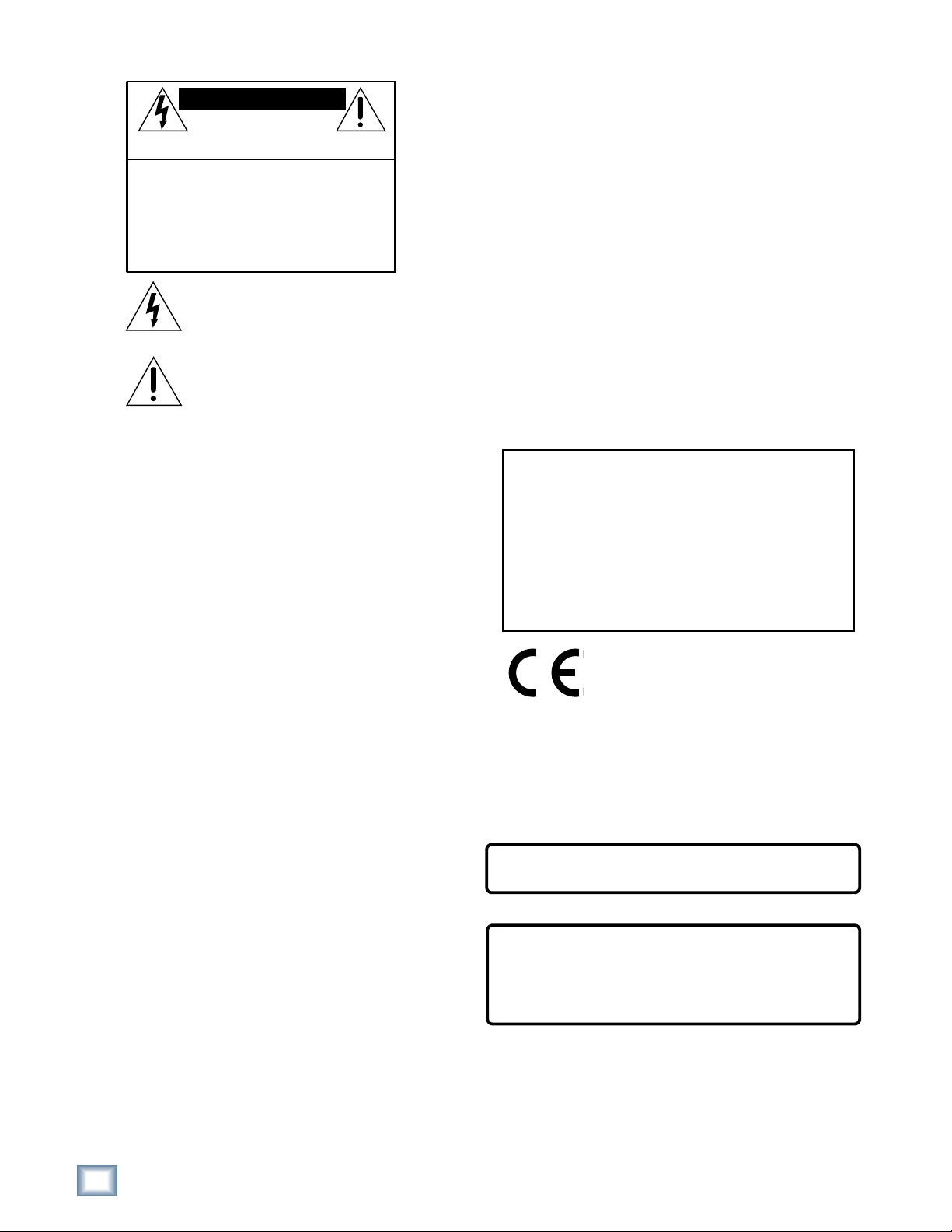
System Control Buttons
Most of the group of buttons
immediately above the transport
(“tape deck”) controls open menus in
the LCD. These are the entry points to
TRACK/
DELETE LAST PROJECT BACKUP DISK UTIL SYSTEM DIGI-I/O SYNC DEC INC
EDIT
the LCD menus and are called System
Control buttons.
Page Left and Page Right Buttons
The large < and > buttons are page navigators. If a menu consists of more than
one page, the top line on the 24 character by 4 line LCD readout will display a ←
or → in the upper left or upper right corner to indicate the direction in which you
may page to find more choices within
that menu.
SELECTSELECTSELECT
SELECT
Select Buttons
The four SELECT buttons under the
LCD are aligned under text describing the choices available within that menu.
Examples include Exit, confirmation (OK), increment or decrement a number,
scroll through choices, or advance through operational tiers (“follow the signs, you
won’t get lost”). Select buttons are soft buttons whose function changes depending
on the operation you’re performing.
6
MDR 24/96
Pairs of SELECT buttons with << >> displayed above them are used to select
MINUTESHOURS
SECONDS FR AMES
TICKS
BEATS
BARS
among choices or move a cursor ‘v’ through a text field. The (–)DEC and (+)INC
(decrement and increment) buttons scroll through choices in the active field.
Sometimes they duplicate the << >> buttons and, at other times, they interact,
where the << >> buttons select the character that will be changed by the DEC
and INC buttons.
Pressing the SELECT button labeled OK in the display performs the menu
operation in process. There’s usually a button labeled Cancel should you decide
not to complete an operation. Pressing any menu button will also back out without
performing the operation.
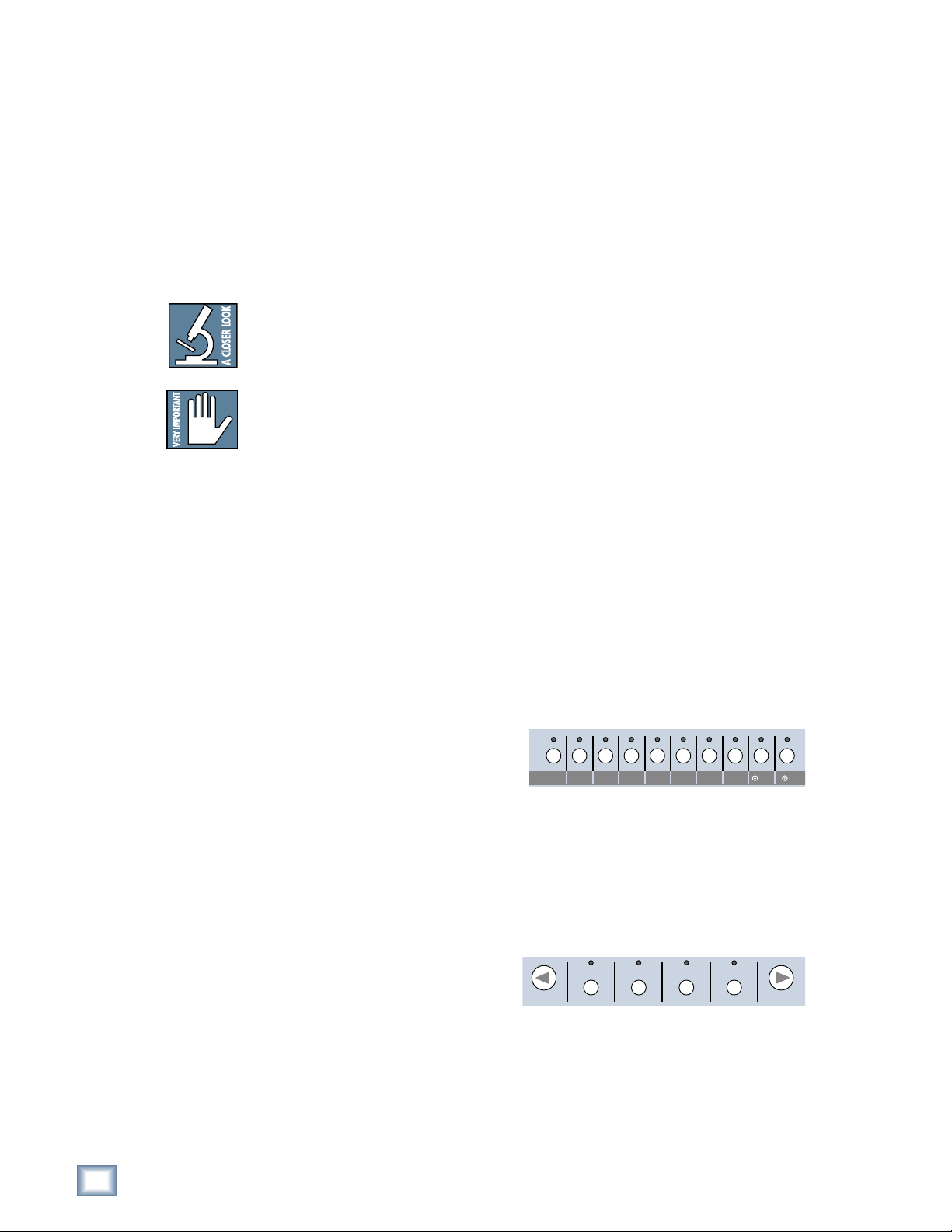
Front Panel Display and Controls
The (–)DEC and (+)INC (decrement and increment) buttons are
used to modify an alphabetical or numerical parameter displayed in
the LCD such as Project Name or Time Code Offset. If the red LEDs
above the buttons are glowing, they’re active. Generally you can tell
that a character can be edited with the (–)DEC and (+)INC buttons
if it’s sitting above a pair of << >> characters. The Select buttons
below the << >> characters move a ‘v’ cursor along numeric field, indicating
which character will be changed by pressing the (–)DEC and (+)INC buttons.
Any time you’re working in a menu, LED’s will illuminate above any button that
does something within that menu. Some operations, particularly those which could
be disastrous like deleting data that can’t be recovered, offer you a Cancel option,
allowing you to quit without changing anything.
Depending on the menu and how many layers it has, Exit or Cancel may bring you
back to a previous menu or all the way back to the top. You can also leave the
menu by pressing the button that got you there (its red LED will be lit to remind
you where you are), or by pressing the left < button when the ← symbol isn’t
displayed. You need not completely exit one menu before moving to another; just
press another menu button to jump into a new menu.
Transport Controls
Transport operating controls are described in detail in other sections of this
manual, so they won’t be repeated here. This section describes the front panel
displays and the setup and system function buttons located below the LCD.
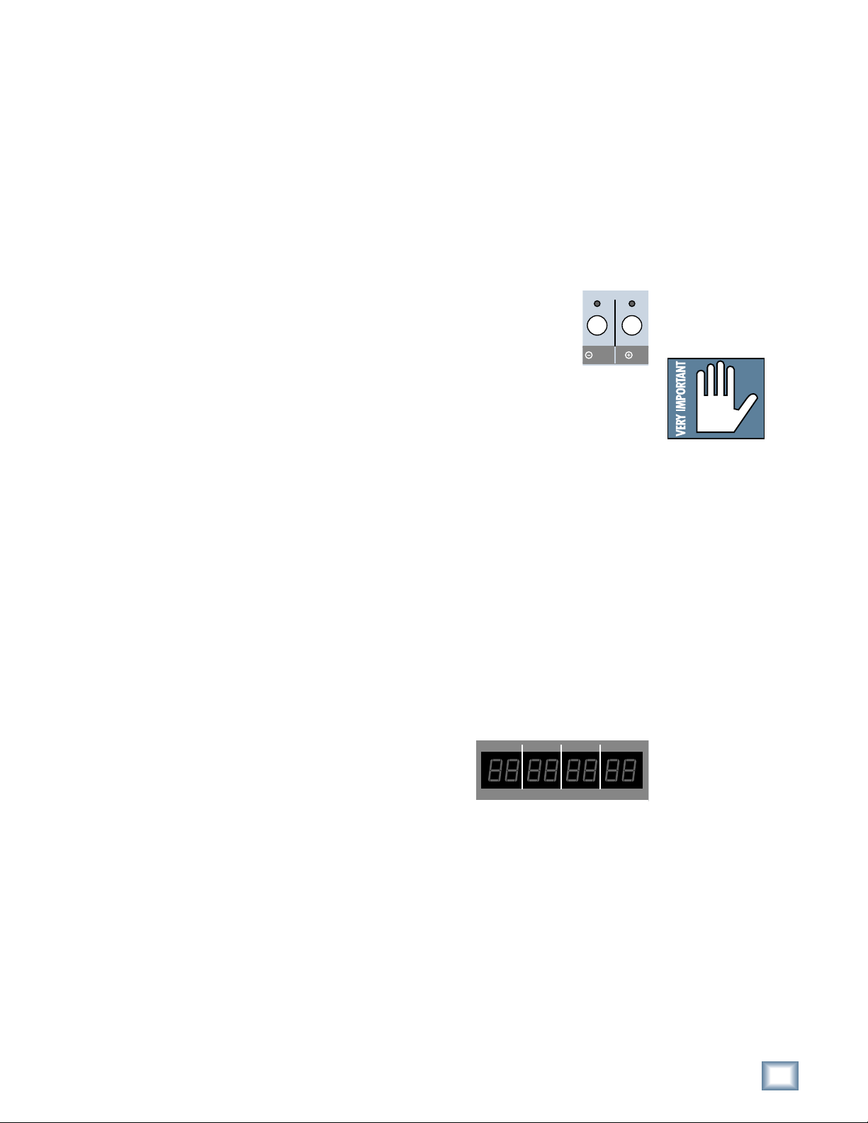
Current Time Display
Current transport time is displayed in either
Hours:Minutes:Seconds:Frames (SMPTE time) or
musical score position in Bars:Beats:Ticks (BBT) if
you are working on a project brought over from an
HDR24/96. The project must be displaying BBT
when last saved on the HDR. The display cannot be changed from the MDR24/96
directly.
DEC INC
Note:Note:
Note: Whether or not a
Note:Note:
“Cancel” or “Exit”
prompt appears above a
SELECT button, it’s okay
to jump directly to one
of the other top level
menus without responding to a prompt. It’s a
quick “bail out” in case
you’ve discovered that
you’re in the wrong menu
for what you want to accomplish. Skipping an
OK, Cancel, or Exit
prompt will not harm or
hang the MDR24/96.
Operation Guide
In BBT mode, the front panel display only shows tick numbers when the transport
is stopped. When running, the Ticks field contains hyphens (- -). Leading spaces in
the Bars field are also filled with hyphens, as: - - 73:04:45. Bar numbers greater
than 999 are displayed as hyphens. However, the display still counts beats (01
through 04) while the transport is running.
Operation Guide
7
Status LEDs
The group of LEDs to the left of the time code display
indicates the state of several of the current setup options.
44.1k
48k
96k
MDR 24/96
• 44.1k, 48k and 96k LEDs indicate the selected
sample rate.
• VARI indicates that the sample rate is controlled by
an external word clock source or video sync signal.
• 16 BIT and 24 BIT indicate the selected word length.
• ERROR indicates a clock or synchronization error; for example, a word
clock frequency that is out of range.
TC indicates that the transport is receiving acceptable time code. This LED is only
active when the MDR24/96 is set to chase time code. The LED blinks when time
code is expected but is either not present or at the incorrect frame rate. When
everything is in order with time code synchronization, it will be on.
CLOCK indicates that a proper data clock signal is being received. It blinks if the
MDR24/96 is expecting an external clock and it’s not present. If all is well, when
Internal clock is selected, the CLOCK LED will be on.
VARI
ERROR
16 BIT
24 BIT
TC CLOCK
Front Panel Alphanumeric Display (LCD)
The front panel LCD, when not performing a setup or utility operation, is an
informative summary of the current project. A screen saver blanks the display after
ten minutes of display inactivity. To re-activate it, press one of the large < >
buttons or any menu button.
Project Information Display
The following information is displayed
on the MDR24/96 hardware front panel
display after boot-up and whenever any
front panel operation is exited.
PROJECT: [Name of the currently loaded project]
PLAYLIST: [The currently loaded playlist version]
DRIVE: [The disk drive containing the Project — Internal or External]
AVAIL: [The amount of recording time left on the disk]
The MDR 24/96 allows only one playlist. If a project is brought from an HDR24/96,
the last active playlist is used (you are not able to switch to other playlists from the
MDR24/96).
PROJECT: Project#1
PLAYLIST: Playlist 1
DRIVE: C:Internal
AVAIL: 01:35:00
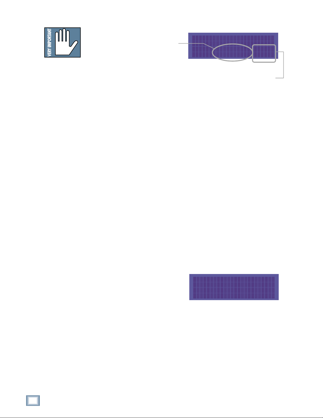
Menu/Status Display
The LCD indicates menu choices and
displays status information when a
time-consuming operation, such as disk
formatting or file copy is in process.
The large < and > buttons scroll
through the menu horizontally if there
are more choices within the current level menu than can be displayed in the
available display area. An arrow ← or → at the top corner of the display indicates
that more choices are available, and in which direction to scroll in order to view them.
SYNC OPTIONS [1]->
Sample Time Code
Clock Rate Source Rate
8
MDR 24/96
About “Tape”
No, you’re not reading the wrong manual. Our goal was to build a hard disk recorder that is
comfortable for someone familiar with tape recording, but that doesn’t require you to get a
brain transplant from a computer geek to use. When familiar terms such as Tape Inputs,
Tape Returns, Transport, and the like are applied to the MDR24/96, they mean exactly
what you expect them to mean. Where the well-worn shoe fits, we continue to wear it.
Overview
By combining traditional multitrack tape recording features with the power and flexibility
of hard disk recording, the Mackie Designs MDR24/96 takes multitrack recording to a
level never before achieved by a product in its price range. In addition to the standard
battery of traditional tape-based features, the MDR24/96:
• Combines the familiarity of a multitrack tape machine with the security of nondestructive recording and non-degrading recording media.
• Records simultaneously on all 24 tracks at 44.1 or 48 kHz and on 12 tracks at
88.2 or 96 kHz. At 48 kHz the internal hard drive stores over 2200 track-minutes
of 24-bit audio (90 minutes of 24 full tracks). That’s more than six reels of 2-inch
tape at 30 inches per second! At 96 kHz the drive stores 1100 track-minutes of
24-bit audio (45 minutes of 24 full tracks).
• Has eight Virtual Takes per track, allowing you to record multiple passes without
having to change routing and bussing assignments or use additional tracks.
Operation Guide
• Iinterfaces with any analog or digital console. The MDR24/96 uses the same I/O
cards as the Mackie Digital 8•Bus console: the AIO•8 (24-bit analog A/D and
D/A), DIO•8 (TDIF/ADAT Optical), PDI•8 (AES/EBU), OPT•24 and low-cost
OPT•8 (ADAT Optical).
• Provides three convenient methods of backup: Mackie Media M•90, a removable
hard drive (also capable of 24-track recording and playback), Mackie Media
PROJECT, a removable drive using inexpensive, removable 2.2 GB ORB
cartridges; and data transfer to another computer through the MDR24/96’s
100 Base-T Ethernet port via the built-in FTP server.
• Offers two optional remote control devices — the compact Remote 24 for smaller
project studios, and the full-featured Remote 48 for controlling up to 48 tracks
on two MDR24/96 recorders.
Record Ready
24TRACK/24BIT DIGITAL AUDIO HARD DISK RECORDER
OL
OL
OL
OL
OL
2
2
2
4
4
4
7
7
7
10
10
10
15
15
15
20
20
20
25
25
25
30
30
30
35
35
35
40
40
40
50
50
50
REC REC REC REC REC REC REC REC REC REC REC
OL
2
2
2
4
4
4
7
7
7
10
10
10
15
15
15
20
20
20
25
25
25
30
30
30
35
35
35
40
40
40
50
50
50
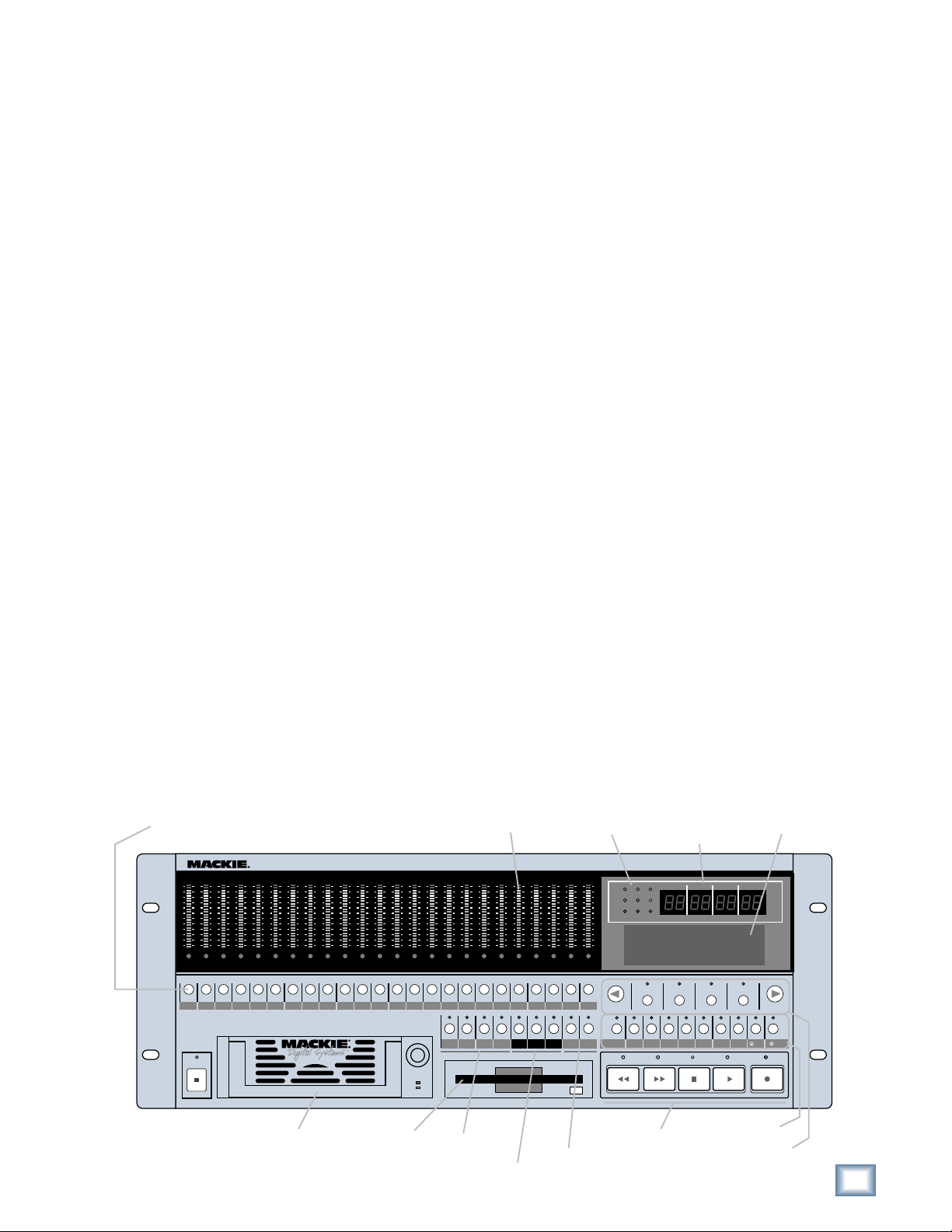
Meter Display
OL
OL
OL
OL
OL
OL
OL
OL
OL
OL
OL
OL
OL
2
2
2
2
2
2
2
2
2
2
4
4
4
4
4
4
4
7
7
7
7
10
10
15
15
20
20
25
25
30
30
35
35
40
40
50
50
7
10
10
10
15
15
15
20
20
20
25
25
25
30
30
30
35
35
35
40
40
40
50
50
50
4
7
7
7
10
10
10
15
15
15
20
20
20
25
25
25
30
30
30
35
35
35
40
40
40
50
50
50
REC
REC REC REC REC REC REC REC REC REC REC REC REC
2
4
4
4
7
7
7
10
10
10
15
15
15
20
20
20
25
25
25
30
30
30
35
35
35
40
40
40
50
50
50
OL
2
2
2
4
4
4
7
7
7
10
10
10
15
15
15
20
20
20
25
25
25
30
30
30
35
35
35
40
40
40
50
50
50
2019181716151413121110987654321
OL
OL
2
2
4
4
7
7
10
10
15
15
20
20
25
25
30
30
35
35
40
40
50
50
21
Status Display
MDR 24/
OL
2
44.1k
4
7
10
15
20
25
30
35
40
50
242322212019181716151413121110987654321
242322
48k
VARI
16 BIT
ERROR
TC CLOCK
PROJECT: Little love
PLAYLIST: Playlist 1
DRIVE: C:Internal
AVAIL: 01:35:00
Current
Time Display
96k
24 BIT
HIGH RESOLUTION AUDIO
96
44.1/48/96K SAMPLE RATES
MINUTESHOURS
BARS
SELECTSELECTSELECT
SECONDS FR AMES
BEATS
TICKS
SELECT
LCD Display
POWER
ON
Media Tray Floppy Drive
LOC 2LOC 1 STORE
Locate &
Loop
Monitoring &
Record Safe
ALL
REC
LOOP
SAFE
1–2
AUTO
AUTO
INPUT
TAKE
INPUT
Auto Take &
Time code
Chase
T-CODE
TRACK/
DELETE LAST PROJECT BACKUP DISK UTIL SYSTEM DIGI-I/O SYNC DEC INC
CHASE
EDIT
REWIND
FAST FWD
Transport
PLAY
STOP
System Control
LCD Control
Operation Guide
RECORD
9
MDR 24/96
Setup and Configuration
This chapter explains how to set up and configure the MDR24/96 for use in your
studio. Two application examples show how to interface the MDR24/96 with
analog and digital recording consoles.
Required Equipment
Of course, there’s more to a studio than a recorder and some musicians. At a
minimum, you’ll need the following to make the MDR24/96 feel at home:
• Three Mackie 8-channel I/O (input/output) cards.
• A console with a minimum of 24 tape sends (buses or direct outputs) and
returns (line inputs or monitor returns). If your analog console has only 8
tape sends, use Y-cord splitters to send Tape Out 1 to MDR24/96 Inputs 1,
9 and 17; Tape Out 2 to MDR24/96 Inputs 2, 10, and 18, and so forth.
• Cables to connect the MDR24/96 to the console: 3 or 6 multi-channel
snakes or fiber optic cables, depending on your I/O setup.
• All the stuff that typically connects to a console: microphones,
instruments, outboard equipment, control room monitors, and so on.
Installation
This section describes how to install the I/O cards and how to connect the
MDR24/96 to your console. Before you begin, you should choose a location for
your MDR24/96 considering the following:
• If you’re not using the Remote 24 or Remote 48, position the front panel
within convenient reach of your normal recording/mixing position. Be
aware that although analog and AES/EBU cables can be fairly long, TDIF
and Remote 24/Remote 48 cables are limited to about 10 meters. ADAT
Optical cables can reach up to about 15 meters.
• The MDR24/96 requires a reliable AC power source with a good ground.
Do not use a ground lift adapter or plug the MDR24/96 into an
ungrounded receptacle. Remember, this is a computer. Using an
uninterruptible power supply (UPS) to power the MDR24/96 is a good idea
to avoid an unexpected shutdown and protect it from transient line voltages.
Warning!
Before applying power to the MDR24/96, make sure that the Voltage Selector
switch next to the AC inlet jack on the rear panel is set to the line voltage used
in your region. Powering-on the MDR24/96 with the Voltage Selector switch
set incorrectly can cause an electrical and fire hazard that may result in
irreparable damage to the unit.
10
MDR 24/96
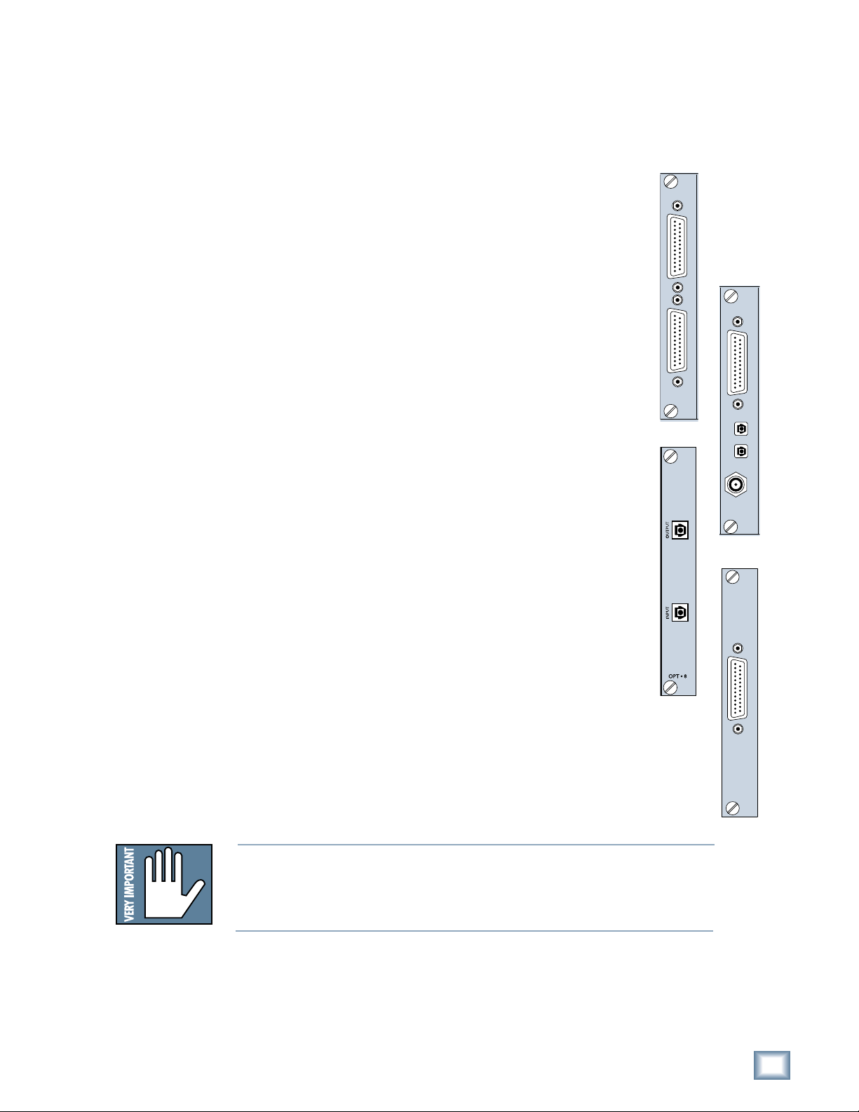
I/O Cards and Cables
While the MDR24/96 ships with AIO•8 cards already installed, three other flavors
of I/O cards are also available. All I/O cards can be mixed and matched in any
combination.
Operation Guide
AIO•8
• Each AIO•8 provides 8 analog line-level inputs and outputs on two 25-pin
D-subminiature (DB25) connectors. These connectors are pin-for-pin
compatible with the analog (not TDIF) DB25 connectors found on the
TASCAM DTRS recorders. DB25 cables that break out to XLR or 1/4" TRS
connectors for mating with your console are readily available.
DIO•8
• Each DIO•8 provides 8 digital inputs and outputs in two formats:
1. TASCAM Digital Interface (TDIF) provides 8 input and output channels
of digital audio on a single DB25 connector. It requires a TASCAM
PW-88D or equivalent TDIF-compatible cable.
2. ADAT Optical provides 8 channels of digital audio on fiber-optic cable.
Two optical cables are required for each card, one for inputs, the other
for outputs. Both cables must connect to the same device, creating a
closed loop.
3. The DIO•8 also provides a TDIF word clock sync output for use with
older TASCAM equipment.
OPT• 8
• The OPT•8 is a low-cost, ADAT Optical-only version of the DIO•8 card.
The previous ADAT information also applies to this card.
PDI• 8
• Each PDI•8 carries four stereo pairs (eight channels) of digital input and
output on a single DB25 connector. This card supports the AES/EBU
(IEC-958 Type 1) digital interfacing standard carrying two channels of
digital audio on a single balanced cable. The PDI•8 can also be configured
for the consumer (IEC-958 Type 2, or S/PDIF) data format if required.
DB25 cables that break out to XLR connectors, and double-ended DB25 to
DB25 AES/EBU cables for mating with your console, are readily available.
AIO•8
ANALOG I/O
OPT•8
INPUT OUTPUT
DIO•8
APOGEE
DIGITAL I/O
ADAT OPTICAL
PDI•8
TDIF
IN OUT
SYNC
AES/EBU I/O
The PDI•8 is the only Mackie I/O card that currently supports 88.2 or 96
kHz operation. At these sample rates, the PDI•8 card runs in “doublewide” (dual-wire) mode. In double-wide mode, the PDI•8 carries four mono
channels of digital I/O by transmitting two consecutive 88.2/96k samples
of the same channel on a single conductor.
Note: Different manufacturers use different wiring standards for DB25 interface cables (both analog and digital) that otherwise look the same. Make
sure the cable you are using is the correct one. See Appendix E for a list of
compatible MDR24/96 I/O card cables.
Operation Guide
PDI• 8
11
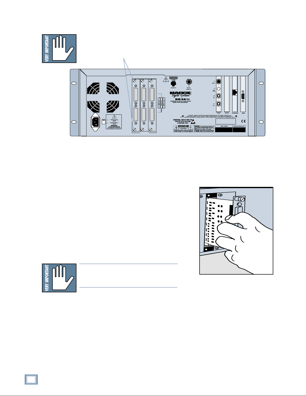
To replace the AIO-8 cards with different I/O cards:
1. If the MDR24/96 is plugged into AC power, unplug it.
2. Unscrew the thumbscrews at the top and bottom of each I/O card to be
removed. Grasp one thumbscrew with each hand and gently pull the card
out.
MDR 24/96
ANALOG I/O ANALOG I/O ANALOG I/O
M
INPUT OUTPUT
INPUT OUTPUT
INPUT OUTPUT
TAPE IN/OUTS
3. Before you take I/O cards from their bags, touch a grounded metal object
to discharge any static electricity from your body.
4. Remove the new I/O card from its anti-static bag and put the I/O
card you just removed from the MDR24/96 into the bag.
5. Hold the new card so the component side
faces left and line up the top and bottom
edges with the white card guides. Push the
card all the way into the slot until its
faceplate is flush with the back panel.
6. Hand-tighten the thumbscrews at the top
and bottom of the card. Do not use a
screwdriver.
12
MDR 24/96
If you want to hook up the MDR24/96 I/O cables
to your console right now, see the console hookup
diagrams in the “Hookups” section (page 23). Be
sure to come right back here when you’re done.
Note:Note:
Note: Always hand tighten the thumbscrews
Note:Note:
at the top and bottom of all I/O cards before operating the MDR 24/96.

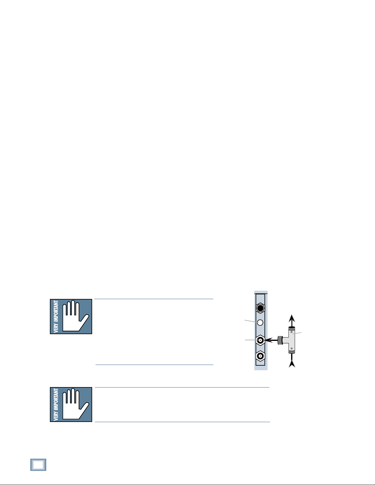
SMPTE Input/
Output
Termination
Switch
Word Clock/
Video Input
Word Clock
Output
Sync Card and Cables - Word Clock and Digital Synchronization
The Sync Card provides ports to synchronize the MDR24/96’s sample clock and
time/transport position to other equipment. The functions of the jacks and switch,
from top to bottom are:
• SMPTE Input / Output – This 1/4" TRS jack serves as an input when
slaved to incoming SMPTE time code, and as an output when generating
SMPTE time code to synchronize other devices with the MDR24/96.
• Termination Switch – This pushbutton switch selects the termination
impedance of the Word Clock / Video Input jack. When the switch is out,
the impedance is 3.3kΩ (bridging); when in, the impedance is 75Ω
(terminated).
• Word Clock / Video Input – This BNC jack receives either word clock,
composite video, or video blackburst as determined by the MDR24/96
SYNC
Whenever digital audio connections are made between devices, the sample clock
of every device must run at exactly the same rate. This is usually accomplished by
selecting one device as the “master” clock source and distributing its word clock
signal to all the “slave” devices in the system. The master is configured to run
from its internal clock, and the slaves from external word clock. Some digital
interfaces are self-clocking (such as the AES input on many DAT machines) and
do not require a separate work clock connection. Others simply cannot be
configured as slaves. The master/slave designation must be made correctly for
each device to avoid the clicks and pops associated with asynchronous clocks.
Sample Clock setting. Use this input when the MDR24/96 is operating as a
word clock slave.
• Word Clock Output – This BNC jack transmits word clock to other devices
in the system when the MDR24/96 is configured as the clock master.
Operation Guide
Whenever time code (positional) synchronization is used, all the devices in a
system, both analog and digital, must be synchronized to a common timing (speed)
reference. This is often achieved by distributing video from a master video sync
generator (sometimes called “house sync”) to all the slave devices in the system
when word clock cannot otherwise be used. The MDR24/96, like many other
digital devices, can synchronize its sample clock to a video signal. However, video
does not provide enough timing precision to properly synchronize devices whose
digital audio paths are interconnected; word clock must be used instead.
Generally it doesn’t matter which device in a system serves as the word clock
master, except when synchronizing to time code or video. For example, if your
MDR24/96 Inputs and Outputs are connected to the Tape Inputs and Outputs of a
Mackie Digital 8•Bus console using TDIF, either the MDR24/96 or D8B can be the
word clock master. However, if you later synchronize the MDR24/96 to time code
from a VTR, you must lock the VTR and MDR24/96 to a master video sync source
and lock the D8B (which can’t sync to video) to word clock from the MDR24/96.
In this case the MDR24/96 becomes both a video slave and a word clock master.
For more detailed information on setups involving video and time code
synchronization, see the HDR24/96 Technical Reference manual, available to
download at www.mackie.com.
Note: Note:
Note: For audio-for-video applications, the MDR24/96 can lock its word clock to
Note: Note:
a video signal. In this configuration, there must be only one word clock dependent device (The MDR24/96) locked to the video source. The MDR24/96 then
becomes the word clock master for the other digital devices in the system (for
example, a digital mixing console). Do not attempt to lock multiple digital devices to the video signal, or you’ll get clicks.
Operation Guide
13
MDR 24/96
The following are recommended setups for establishing proper sample clock
synchronization with the devices connected to the MDR24/96 digital I/O cards.
TDIF (DIO•8)
With the MDR24/96 as a master, connect Word Clock Out of the MDR24/96
to Word Clock In on the receiving device(s). If connecting to older TASCAM
DTRS recorders, use the Sync Out port on the first DIO
Word Clock Out. If there is more than one DTRS recorder in the chain,
connect Sync Out to the word clock input of the first DTRS recorder only; the
other recorders are synchronized through their interconnecting DTRS cables.
With the MDR24/96 operating as a slave to another TDIF device, connect the
word clock output from the master TDIF device to Word Clock In on the
MDR24/96.
•8 card instead of
ADAT Optical (DIO•8, OPT•8)
With the MDR24/96 as a master, set the receiving device(s) to derive sample
clock from their ADAT Optical ports if the ports are self-clocking. In this
case, no word clock connection is necessary. If the ADAT Optical ports on the
receiving devices are not self-clocking, connect Word Clock Out of the
MDR24/96 to Word Clock In on the receiving device(s).
With the MDR24/96 configured as a slave, connect the word clock out of the
master ADAT Optical device to Word Clock In on the MDR24/96.
AES/EBU (PDI•8)
With the MDR24/96 as a master, set the receiving device(s) to derive their
sample clock from the AES/EBU ports if the ports are self-clocking. In this
instance, no word clock connection is necessary. If the AES/EBU ports on the
receiving device(s) are not self-clocking, connect Word Clock Out of the
MDR24/96 to Word Clock In of the receiving device(s).
With the MDR24/96 as a slave, connect the word clock out of the master
AES/EBU device to Word Clock In on the MDR24/96.
Note:Note:
Note: Use 75 Ω coaxial cables when con-
Note:Note:
necting word clock or video to the Sync
Card Word Clock/Video input jack. If the
Termination
Switch
Word Clock to
other Slaves
MDR24/96 is at the end of a cable that’s
connected to several devices, push the
Termination Switch in; otherwise leave it
Word clock
input jack
out and use a BNC Tee adapter to feed the
signal on to the next device in the chain.
Note:Note:
Note: If you are using an MDR24/96 with the Mackie Digital
Note:Note:
SYNC
Word Clock
From Master
8•Bus console, you may need to turn on the Digital 8•Bus first.
The Clock I/O on the D8B prefers not to see an active signal at
its Word Clock input when it powers up.
BNC-Tee
adaptor
14
MDR 24/96
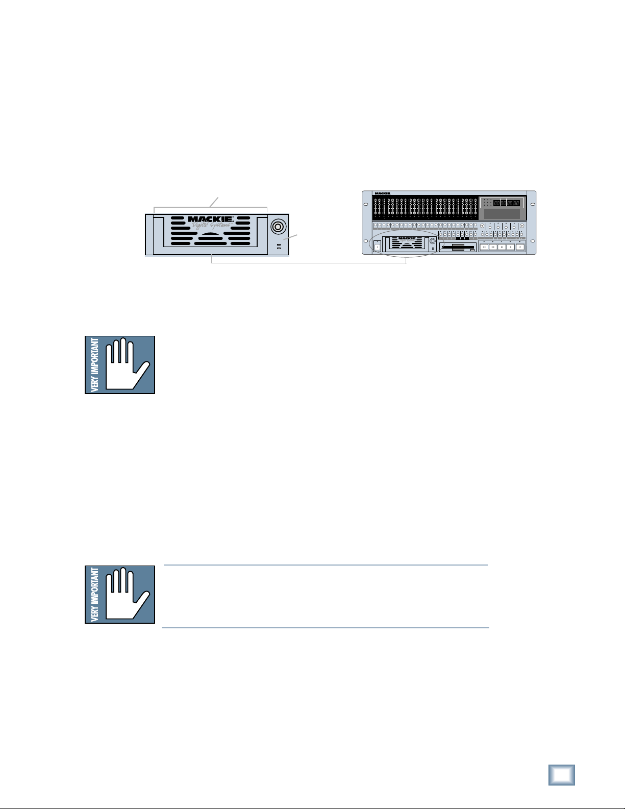
Mackie Media (Optional)
The MDR24/96 emulates the tape library tradition with Mackie Media M•90 and
Mackie Media PROJECT drives. Both drives come complete with a plug-in tray for
quick removal and a nifty storage case for shelving and transporting the drives.
Trays can be purchased separately if you want to use your own UDMA IDE drives.
The MDR24/96 can record or play directly off the M
sessions as quickly as changing tape on a 24-track—no backup time required.
PROJECT drives are for backup only and use removable 2.2GB ORB cartridges that
fit in your pocket. Each can hold a couple of 5-minute 24-track masters.
Mackie Media Tray
Mackie Media
Receiver
To install or remove a Mackie Media tray:
1. Power the MDR24/96 off whenever inserting or removing media trays.
If you have an active project, don’t forget to save it first!
•90 so you can change
24TRACK/24BIT DIGITAL AUDIO HARD DISK RECORDER
OL
OL
OL
OL
OL
OL
OL
OL
OL
OL
OL
OL
OL
OL
OL
OL
2
2
2
2
2
2
2
2
4
4
4
4
4
4
4
4
7
7
7
7
7
7
7
7
10
10
10
10
10
10
10
10
15
15
15
15
15
15
15
15
20
20
20
20
20
20
20
20
25
25
25
25
25
25
25
25
30
30
30
30
30
30
30
30
35
35
35
35
35
35
35
35
40
40
40
40
40
40
40
40
50
50
50
50
50
50
50
50
REC REC REC REC REC REC REC REC REC REC REC
POWER
ON
2
4
7
10
15
20
25
30
35
40
50
OL
2
2
2
2
2
2
2
4
7
10
15
20
25
30
35
40
50
2
4
4
4
4
4
4
4
7
7
7
7
7
7
7
10
10
10
10
10
10
10
15
15
15
15
15
15
15
20
20
20
20
20
20
20
25
25
25
25
25
25
25
30
30
30
30
30
30
30
35
35
35
35
35
35
35
40
40
40
40
40
40
40
50
50
50
50
50
50
50
REC
REC REC REC REC REC REC REC REC REC REC REC REC
LOC 2LOC 1 STORE
OL
OL
2
2
4
4
7
7
10
10
15
15
20
20
25
25
30
30
35
35
40
40
50
50
REC
LOOP
SAFE
1–2
OL
OL
OL
OL
2
2
2
2
4
4
4
4
7
7
7
7
10
10
10
10
15
15
15
15
20
20
20
20
25
25
25
25
30
30
30
30
35
35
35
35
40
40
40
40
50
50
50
50
242322212019181716151413121110987654321
242322212019181716151413121110987654321
ALL
AUTO
T-CODE
AUTO
INPUT
TAKE
CHASE
INPUT
HIGH RESOLUTION AUDIO
MDR 24/
96
44.1/48/96K SAMPLE RATES
MINUTESHOURS
SECONDS FRAMES
44.1k
48k
96k
VARI
24 BIT
16 BIT
ERROR
TC CLOCK
BEATS
BARS
PROJECT: Little love
PLAYLIST: Playlist 1
DRIVE: C:Internal
AVAIL: 01:35:00
DELETE LAST PROJECT BACKUP DISK UTIL SYSTEM DIGI-I/O SYNC DEC INC
REWIND
TICKS
SELECT
SELECTSELECTSELECT
TRACK/
EDIT
PLAY
FAST FWD
STOP
RECORD
Operation Guide
2. To remove a drive, first unlock it by inserting the key and turning it a
quarter-turn counterclockwise. Two keys are packed with the recorder, and
one with each M•90 drive.
3. Lift the bail handle to release the drive, and pull it out of the drive bay.
4. To install a new M•90 or PROJECT drive, slide the media tray into the
front panel drive bay. Press it firmly into place, and latch it by pressing the
bail handle downward until it’s fully seated.
5. Insert the key into the lock and turn it a quarter-turn clockwise. The key
locks the drive into place and powers the tray.
6. The MDR24/96 will automatically detect the Mackie Media drive when you
next power it up.
Note: Note:
Note: Mackie Media are hard drives, and as we all know, hard drives
Note: Note:
involve some pretty intricate technology. So don’t shake the little
darlin’, and if a tray has just come in from a freezing car or airplane
cargo hold, do not install it until it has reached room temperature.
Operation Guide
15
Note:Note:
Note: The Remotes
Note:Note:
duplicate nearly all
of the front panel
operating controls.
MDR 24/96
When we describe a
front panel opera-
tion, you’ll probably
find it available on
the Remote also. If
you have a Remote,
try it both ways. If
you don’t have a Re-
mote yet, think of
how convenient it
would be.
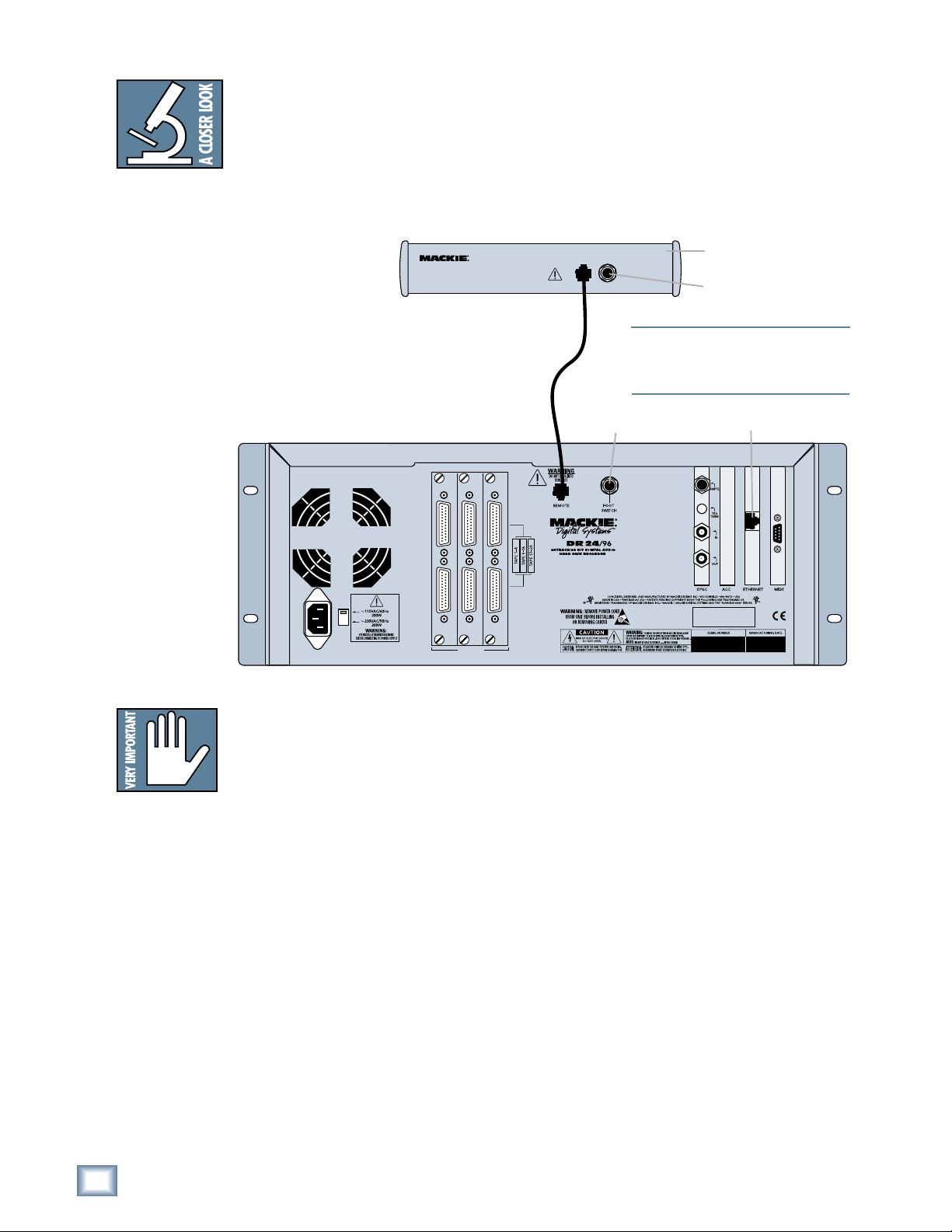
Remote 24 / Remote 48 (Optional)
Installing either remote is as simple as plugging in a telephone. Connect one end
of the cable (supplied with the Remote) to the REMOTE jack on MDR24/96 rear
panel, and the other end to the TO HDR REMOTE JACK jack on the Remote 24,
or to the TO HDR jack on the Remote 48. It’s OK to plug or unplug either Remote
with the MDR24/96 powered on. However, if you plug the Remote 48 into the
MDR24/96 while both are powered on, you must power cycle the Remote 48 to
reset the connection.
REMOTE 24
Remote
connection
ANALOG I/O ANALOG I/O ANALOG I/O
WARNING
DO NOT PLUG INTO
ETHERNET
TO HDR/MDR
FOOT SW
REMOTE JACK
Footswitch
Note:Note:
Note: The MDR24/96 ‘REMOTE’ and Eth-
Note:Note:
ernet jacks both accept CAT-5 Ethernet
cables - don’t get them mixed up!
Back panel of the
Mackie Remote 24
Footswitch
Ethernet Jack
Note:Note:
Note: If you are us-
Note:Note:
ing an MDR24/96
with the Mackie
Digital 8•Bus con-
sole, you may need
to turn on the Digi-
tal 8•Bus first. The
Clock I/O on the
D8B prefers not to
see an active signal
at its Word Clock
input when it
powers up.
M
INPUT OUTPUT
INPUT OUTPUT
INPUT OUTPUT
TAPE IN/OUTS
Footswitch (Optional)
For hands-free do-it-yourself punches and other frequently-used functions like
Play/Stop, Punch In/Out, and Take Select, connect the cable of a momentary,
normally open footswitch to the FOOT SWITCH 1/4" TS jack on the rear panel of
the MDR24/96, the Remote 24, or Remote 48. If you have a Remote installed you
can connect two foot switches, one to the MDR24/96 and one to the Remote. Each
footswitch functions independently of the other. Footswitch functionality is
assigned in the front panel System menu.
Power-Up
OK, NOW you can turn it on. Assuming you have already connected the MDR24/96
to your console, power up the MDR24/96 first, then the outboard equipment and
console, and finally the power amplifiers or powered monitors. Audio equipment
tends to generate unexpected clicks and pops when you power it up, so by
powering up your monitoring system last, you’ll save your speakers and your ears.
Before you read the next section, take a quick, self-guided tour of the front panel
display and controls to get a sense of where they are.
16
MDR 24/96
Note:Note:
Note: The front
Note:Note:
panel display’s back-
light sw it ches off
aft er several min-
utes of inactivity. It’ll
come back on auto-
matically when it’s
needed to display
new information, but
you can revive it at
any time by pressing
either the Page Left
<<
(
<) or Page Right
<<
>>
(
> ) b ut to n below
>>
the display.
Configuration
Before starting a Project, you will need to configure the MDR24/96 I/O card
options and synchronization parameters. These parameters determine where the
sample clock is coming from, how fast the sample clock runs, and how many bits
are recorded in every sample. Some options, like sample rate and bit depth, will
become “standards” that you won’t need to change very often. Others, like Time
Code Source, you may need to change from project to project.
I/O Cards
Only the DIO•8 and PDI•8 cards require special configuration. If you are using
AIO•8, OPT•8, or OPT•24 cards only, you can skip to the next section.
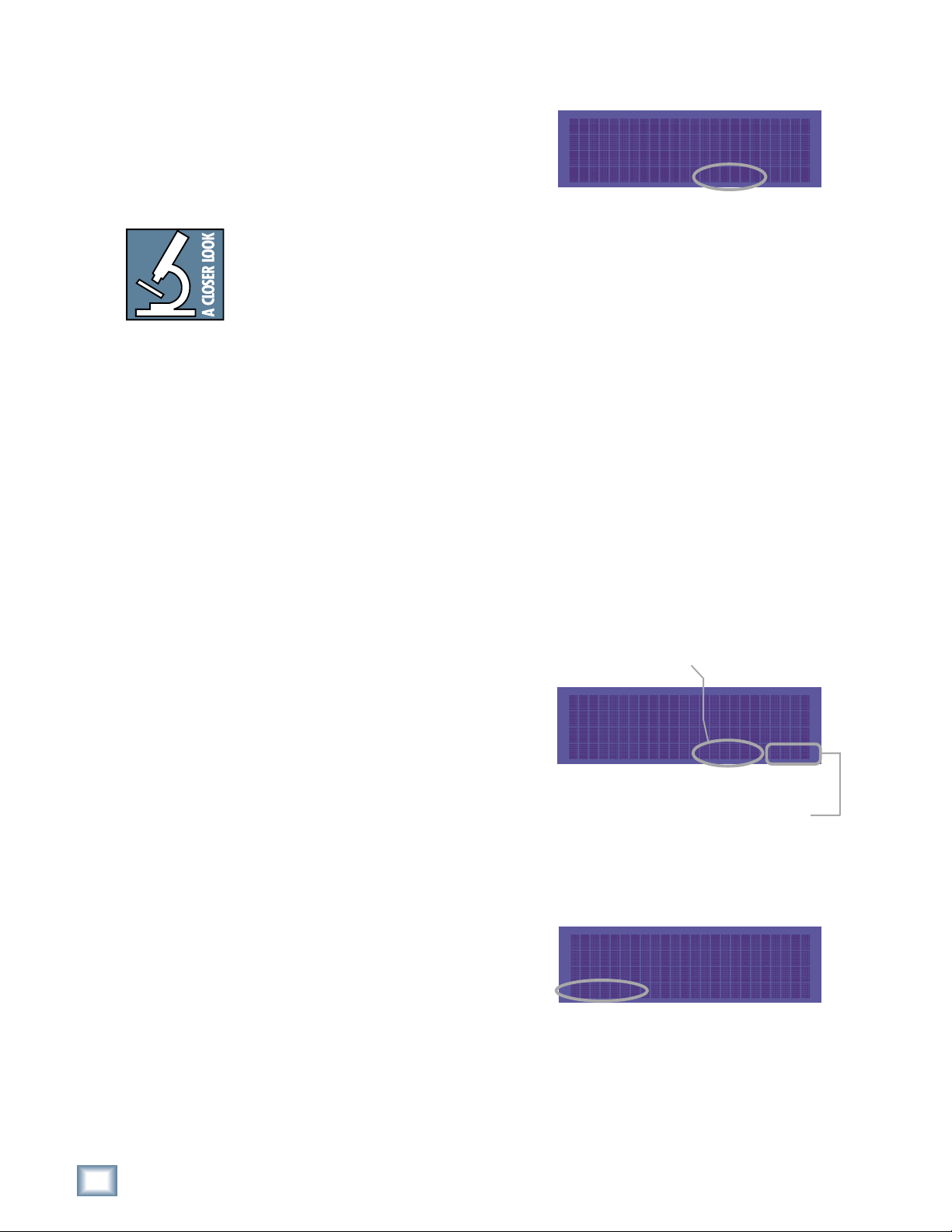
DIO•8 Card
To set the DIO•8 input and output formats:
1. Press DIGI-I/O to enter
the Digital I/O Card Setup
menu.
DIGI-I/O
2. Select In.
The SETUP TAPE INPUTS menu
shows you the current input settings
for each of the three I/O cards.
3. Press the SELECT button
corresponding to each DIO•8 card
and toggle the selection between
ADAT and TDIF.
4. Press the Page Left (<) button to return to the previous screen.
5. Now select Out.
The SETUP TAPE OUTPUTS menu
shows you the current output settings
for each of the three I/O cards.
6. For each DIO•8 card present,
press the SELECT button to
choose the desired output format. Or, select the TD–>AD or AD–>TD
option to convert between formats, bypassing the MDR24/96 tape signal
path entirely.
7. When done, press DIGI-I/O to exit the menu.
DIGITAL I/O Card Setup
Stat Rate
In Out Bits Convert
(SETUP TAPE INPUTS)
1-8 9-16 17-24
ADAT ADAT ADAT
(SETUP TAPE OUTPUTS)
1-8 9-16 17-24
ADAT ADAT ADAT
Operation Guide
Operation Guide
17
PDI•8 Card
The PDI•8 card options include sample rate conversion for each stereo AES/EBU
input, and status bit control (pro/consumer mode) for each output. When a PDI•8
card is first installed, its default settings are for sample rate conversion Off, and
channel status bits set to indicate the Pro (AES/EBU) format. In most
circumstances you won’t need to change these settings. However, if the device(s)
connected to the PDI•8 inputs cannot be made a clock master or slave (such as a
CD player with a digital out), enabling sample rate conversion on each affected
input will effectively re-clock the incoming data.
MDR 24/96
Occasionally you’ll run across a device that will not recognize the digital audio
output from the PDI•8 card. Changing the status bits on the affected output(s)
from Pro to Consumer (S/PDIF) may solve the problem.
Remember that with the AES/EBU format, channels come in pairs, so rather than
eight settings, you have four, one for each pair of channels.
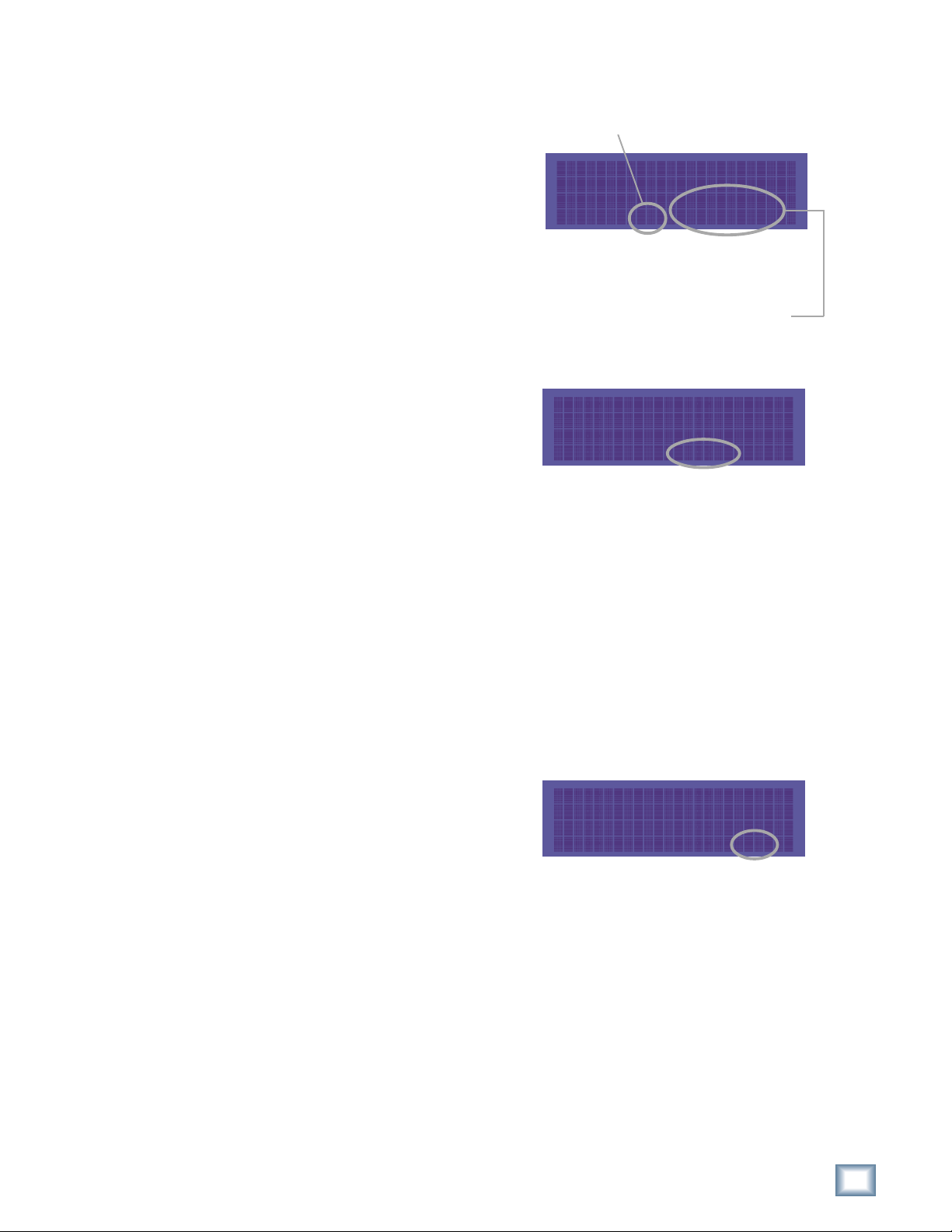
To set the PDI•8 card options:
1. Press DIGI-I/O to enter the
DIGITAL I/O Card Setup
menu.
DIGI-I/O
2. Select Rate Convert. The
SAMPLE RATE CONVERT
menu shows you the sample rate
conversion settings for inputs 1-8.
DIGITAL I/O Card Setup
Stat Rate
In Out Bits Convert
SAMPLE RATE CONVERT ->
3. Press the SELECT button
corresponding to the desired input
channel(s) and toggle the selection.
On enables sample rate conversion,
Off disables it (default).
4. Press the Page Right (>) button to scroll to channels 9-16. Repeat the
procedure for channels 9-16 and 17-24. Press Page Left (<) until you
return to the DIGITAL I/O Card Setup menu.
1-2 3-4 5-6 7-8
ON OFF OFF ON
18
MDR 24/96
5. Select Stat Bits. The SETUP
STATUS BITS menu shows you the
current status bit settings for
outputs 1-8.
SETUP STATUS BITS
1-2 3-4 5-6 7-8
Pro Pro Pro Consu
6. Press the SELECT button
corresponding to the desired output channel(s) to toggle the selection
between Pro (default) and Consu.
7. Press the Page Right (>) button to scroll to channels 9-16. Repeat the
procedure for channels 9-16 and 17-24. Press DIGI-I/O to exit.

Synchronization
Synchronization Options
Sample Clock
The Sample Clock setting determines the
source of the MDR24/96 sample clock. If
the MDR24/96 is a clock master or is not
connected to any other digital device(s),
set it to Internal. If the MDR24/96 is a
word clock slave, set it to Word Clock.
When Video is selected as the clock source, an additional parameter, the video
frame rate is required. This is actually set as the Video Field Rate (twice as fast).
Video Field magically appends itself to the list of Sync Options in the LCD display.
However, you’ll have to hunt it down as there are normally 3 pages of Sync
Options and Video Field appears on a new page 4. Video Field Rate options are
B&W (60Hz), NTSC (59.94 Hz), and PAL (50 Hz). If you’re doing post in the U.S.
then choose NTSC, and if you’re doing post (or music) in Europe then choose
PAL. If you’re doing music in the U.S. and you’re just using a black burst
generator to keep the clocking universal and solid for the studio, then set the field
rate as well as the BB Generator to use 60 Hz. The integral number of frames per
second will make you much happier than NTSC ever will. The 60 Hz setting can
also be used in HDTV production, where many permutations of frame rate and
raster lines are available.
SYNC OPTIONS [1]->
Sample Time Code
Clock Rate Source Rate
SYNC
Operation Guide
Note:Note:
Note: The PDI·8 is the
Note:Note:
only Mackie I/O card
that currently supports
88.2 or 96 kHz operation. Do not operate
the MDR24/96 at
these Sample Rates
with AIO·8, DIO·8, or
OPT·8 cards installed.
Sample Rate
The Sample Rate determines how fast the
MDR24/96 sample clock runs. Compact
discs use a 44.1 kHz sample rate, while
some DVD disks use 96 kHz. The video
production folks prefer 48 kHz because
their digital video recorders use 48 kHz.
Even though the MDR24/96 supports four Sample Rates, you can only choose
between two at any given time. The range of available rates is determined by the
current Project’s Sample Rate mode. The Sample Rate mode determines whether
a Project will be a 24-track 44.1 kHz or 48 kHz Project, or a 12-track 88.2 kHz or
96 kHz Project. To change the Sample Rate to a setting that is not available, first
create or open a Project with the desired Sample Rate mode.
SYNC OPTIONS [1]->
Sample Time Code
Clock Rate Source Rate
Bit-Depth
The Bit Depth setting determines how
many bits are contained in each audio
sample recorded to disk (the bit
“resolution”). While 16-Bit audio takes
up 1/3 less disk space than 24-Bit audio,
24-Bit audio offers the potential for
greater dynamic range (the difference between the softest and loudest sounds that
can be recorded) and captures a more accurate “image” of the sound.
<- SYNC OPTIONS [3]
Bit Generate TC
Depth SMPTE MTC Offset
Note:Note:
Note: You must still select the MDR24/96’s Sample Rate even if it’s slaved to an-
Note:Note:
other device’s clock. If you don’t set it correctly, the MDR24/96 time display will
run at the wrong rate, even though audio will play at the right speed.
Operation Guide
19
Time Code Chase
If the MDR is set to slave to external time
code (MTC or SMPTE time code),
engaging the Time Code Chase mode
causes the MDR24/96 transport to follow
time code coming from an external master
source. If disengaged, the MDR will go off
line and will no longer follow the external time code. This function is enabled with
the T. CODE CHASE button.
SYNC OPTIONS [1]->
Sample Time Code
Clock Rate Source Rate
MDR 24/96
Note: Note:
Note: When oper-
Note: Note:
ating in sync with
external time code,
you’d nomally stop
the MDR24/96 by
stopping the time
code master, not
the recorder. If
you’re recording
when chasing time
code, pressing Stop
or Play will punch
out of recording.
In the Time Code Chase mode, pressing the PLAY button causes the transport to
wait in an armed state for time code to start. Start, stop, wind, and locate
functions follow the time code master.
The MDR24/96 does not resolve its word clock to incoming time code, it only uses
time code to synchronize transport time. Once the MDR24/96 transport has
jumped to the time code time and started running, it runs on its internal clock,
while continuously monitoring the incoming time code. It will stay locked as long
as the time code doesn’t drop out or otherwise become corrupt for longer than its
“flywheel” window of ten frames. If the time code problem is corrected within that
window, the MDR24/96 will continue to chase. If not, it will drop out of time code
chase mode and stop.
You can disengage TC Chase on the fly, however, without interrupting the MDR24/96’s
operation. If you’re working with really poor quality time code, for example what
might come from an inexpensive VCR, by disengaging TC Chase after the MDR24/96
has found its time code-related position, it will free-run and not sweat the unstable
time code. Synchronization won’t be perfect, but this is a means of working with
problem time code.
Time Code Source
The MDR24/96 can chase time code from either MIDI In or SMPTE In. Use Time Code
Source to select either SMPTE or MTC.
Time Code Frame Rate
There are four standard time code frame
rates, each developed for a specific
application. In addition, two of the frame
rates have variations called drop-frame,
mostly used in broadcast applications to correct timing issues caused by the 29.97
frame rate. Use the Time Code Rate option to set the time code frame rate to one
of the following settings: 30, 30 Drop, 29.97, 29.97 Drop, 25 and 24. If you’re not
involved in video or broadcast applications, 30 frames per second (fps) is your best
choice.
SYNC OPTIONS [1]->
Sample Time Code
Clock Rate Source Rate
20
MDR 24/96
MMC Device ID
You can set the MMC (MIDI Machine
Control) Device ID independently for each
group of eight tracks. Most 24-track MMC
control devices share the same Device ID
for the three 8-track blocks.
<- SYNC OPTIONS [2]->
MMC Pre-Roll
Device On Time On
Send MMC
Use MMC On/Off to toggle MIDI Machine Control at the MDR24/96 MIDI Out.
Pre-Roll Time
Preroll is the amount of time by which
the transport location is offset when
jumping to a locate point. If Preroll is
other than zero, the transport will locate
to a point earlier than the locate time by
the amount of time set in the Preroll window. This is useful when you want the
locator to accurately define a point in the song (like when the guitar solo begins),
but when punching in at that point, you want to start rolling a few seconds before
hand. The MDR 24/96 allows you to set a Preroll amount and then toggle the
Preroll on or off as needed.
<- SYNC OPTIONS [2]->
MMC Pre-Roll
Device On Time On
To set the Preroll amount:
1. Press the SYNC button and
press the Right Arrow button
to move to page two of the
SYNC OPTIONS menu.
2. Press the Pre-Roll Time
select button.
<- SYNC OPTIONS [2]->
MMC Pre-Roll
Device On Time On
Operation Guide
3. Use the << and >> select buttons to select Hours, Minutes, Seconds,
or Frames and use the (–) DEC and (+) INC buttons to set the amount
for that field. Press the Zero select button to reset the Preroll amount
to zero.
4. Press the OK select button to return to the SYNC OPTIONS menu
when you are satisfied with the Preroll amount displayed.
Pre-Roll Enable
When Preroll enable is on, Locate points are offset by the Preroll time. When
Preroll enable is off, there is no preroll offset.
To turn Preroll on or off:
1. Press the SYNC button and
press the Right Arrow button
to move to page two of the
SYNC OPTIONS menu.
2. Press the Pre-Roll On select
button.
3. Use the << and >> select buttons to turn Preroll on or off.
4. Press the OK select button to make your selection and to return to the
SYNC OPTIONS menu.
<- SYNC OPTIONS [2]->
MMC Pre-Roll
Device On Time On
Operation Guide
21
Note: It is not pos-
sible to generate and
chase SMPTE time
code simultaneously.
MDR 24/96
If Generate SMPTE is
selected as the time
code Source, an error
message will appear
Time Code Chase.
if you also select
Generate SMPTE/MTC
These options allow you to select whether
SMPTE time code or MIDI time code (or
both) are generated.
<- SYNC OPTIONS [3]
Bit Generate TC
Depth SMPTE MTC Offset
Time Code Offset
This is the amount of time (hours, minutes, seconds and frames) that is added to
the incoming time code value, and the resulting time is the Current Time of the
MDR24/96 when in Time Code Chase. Negative can be selected to subtract the
offset value from the incoming time code.
To set the TC Offset:
1. Select TC Offset from the SYNC OPTIONS menu.
2. Select Set.
Use the Select buttons to move the “vv” cursor among fields, and then use the
Select buttons to change the value. Negative can be selected from the TC
Offset menu.
To configure the MDR24/96 synchronization settings:
1. Press SYNC to enter the SYNC OPTIONS menu. Select Sample Clock.
Select either Internal or Word Clock according to your setup using the
(–)Dec / (+)Inc or << / >> buttons.
2. Select OK to return to the SYNC OPTIONS menu.
3. Select Sample Rate. Using the (–)Dec / (+)Inc or << / >> buttons, set
the Sample Rate to 44.1 kHz or 48 kHz (88.2 kHz or 96 kHz). Select
OK.
4. Move to the third page of the SYNC OPTIONS menu with the Page
Right (>) button.
5. Select Bit Depth. Set the Bit Depth to 16 Bit or 24 Bit using the (–)Dec
/ (+)Inc or << / >> buttons. Select OK.
Word Clock Divisors (88.2/96 kHz operation only)
Some devices that support double-wide
AES at 88.2 and 96 kHz can only
transmit or receive word clock at 0.5x
the Sample Rate. The Word Clock
divisors determine whether Word Clock
In and Word Clock Out run at 1x or 0.5x the MDR24/96 Sample Rate. Both
divisors can be set independently.
<- SYNC OPTIONS [4]
Video SR/2 SR/2
Field In Out
Sync Settings for 88.2/96 kHz operation only:
1. Move to the last page of the SYNC OPTIONS menu with the Page Right
(>) button. Select SR/2 In.
22
2. Set the Word Clock Input divisor to On or Off using the (–)Dec / (+)Inc
or << / >> buttons. Off selects 1x operation, On selects 0.5x operation.
3. Select OK, then Select SR/2 Out and set the Word Clock Output divisor
to On or Off.
4. Select OK and press the SYNC button to exit the menu.
MDR 24/96
 Loading...