

Mackie MB-16, MB-24, MB-32, MB-E, 8BMETER Installation Instructions Manual
...
MB•32/MB•24/MB•16/MB•E
8•BUS METER BRIDGES
MB•32
4. Locate and
identify the hardware that came with
MB•24
MB•16
MB•E
Congratulations on adding a Meter
Bridge to your Mackie Designs 8•Bus
Console. Installation is very straightforward and should take just a few minutes.
The only reason we've included so many
step-by-step drawings is because our art
department wanted something to do on
a rainy day
1
.
■■ a. Two (2) slotted screws;
■ ■ b. Two (2) collar pieces (Note
that there is a small
pin protruding from
the bottom of each
collar piece);
■■ c. Two (2) Allen head screws;
■■ d. Two (2) lockwashers;
■■ e. One (1) allen wrench.
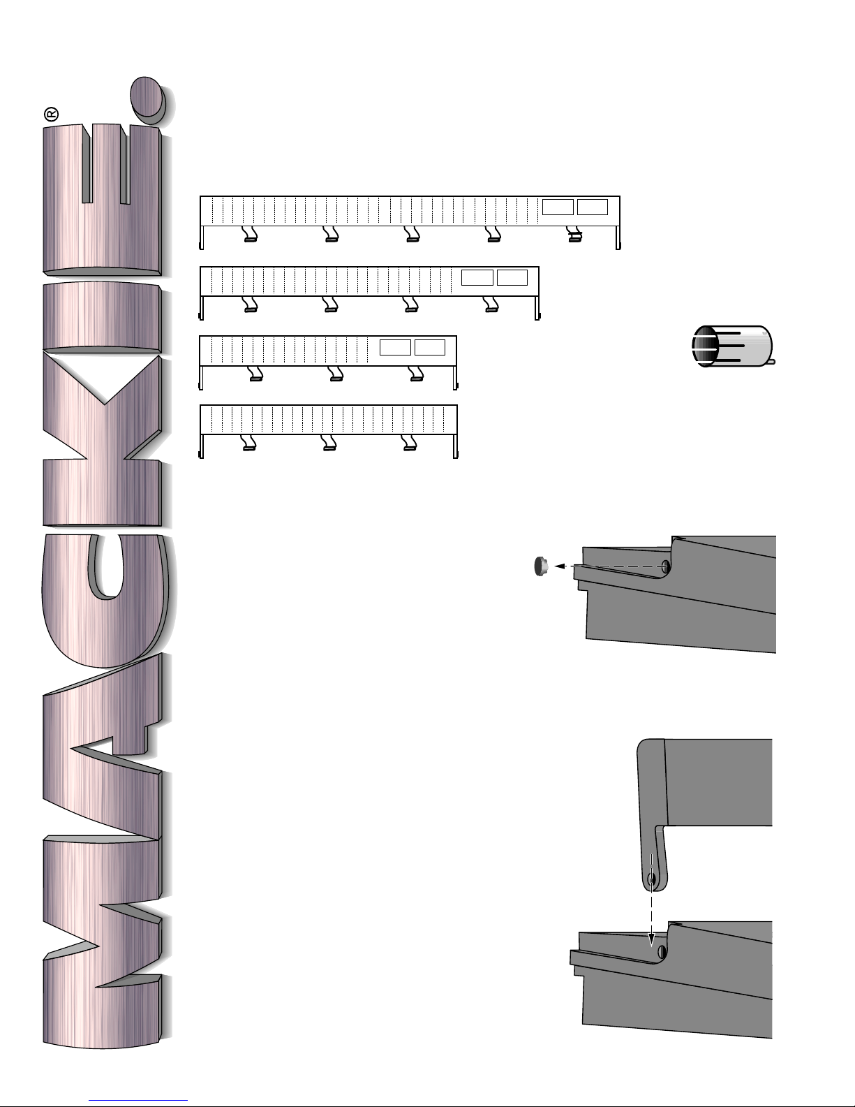
5. Remove the plastic caps that cover
the Meter Bridge mounting holes
on each side of the Console (Drawing A). Feed them to your boa.
your Meter Bridge:
A
INSTALLATION INSTRUCTIONS
1. Locate the warranty card and fill it
out. If you bought your Meter
Bridge at the same time you purchased an 8•Bus series console, you
don't need to answer all the questions on the card that came with the
Meter Bridge. Just fill in the model
number of the Meter Bridge, serial
number, purchase date and dealer,
and your name and address.
2. Make sure that your 8•Bus Console
power supply is turned off.
3. Remove the Meter Bridge from its
plastic bag. Save the bag. It's handy
for wrapping boa constrictors or
moray eels before popping them in
your freezer. Also, save the box.
1
And, since every day except four or five in August are
rainy up here in the Northwest Rainforest, they had time
to do quite a nice job.
.
6. Align the Meter Bridge
with the Console (B) and lower it
into place. Tilt the Meter Bridge
back until it is
at rest against
the Console
chassis (or
your tangle of
patchcords).
Make sure
that the meter
bridge's
mounting
holes line up
B
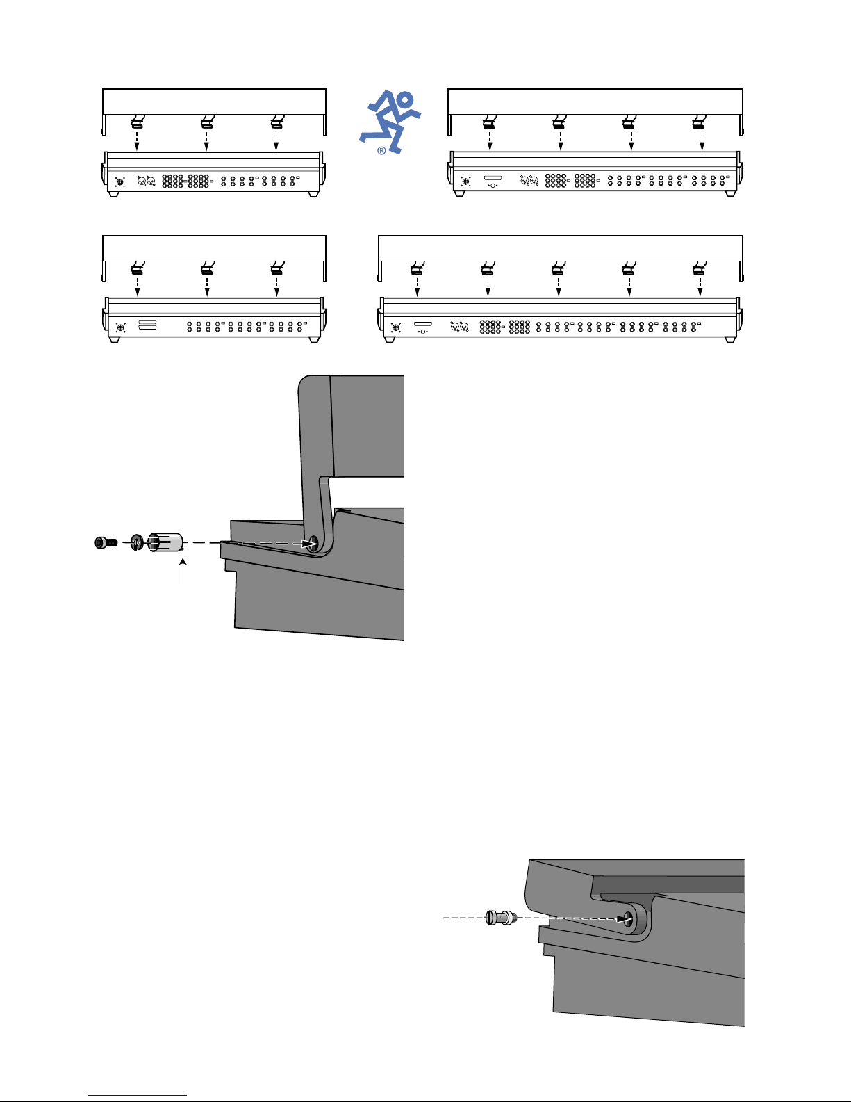
MB•16 Meter Bridge
MB•24 Meter Bridge
E
MB•E Meter Bridge
with the console's mounting
holes.
7. Hand-insert one collar
piece into each side, with
the “teeth” pointing out
(C). Occasionally, the end
caps of the Console will try
C
pin down
to interfere with
this step. Don't get
upset. Simply loosen the CONSOLE end
cap screws, install the collar and then retighten the screws.
8. Turn the collars by hand until you feel the
pin seat itself (it will stop turning).
9. Slide one lockwasher onto each allen-head
screw.
10. Secure the collars by inserting an Allenhead screw on each side (C). Take care not
to cross-thread the screws or strip the
screwheads. Tighten the Allen screws
securely.
11. Using a hefty screw driver, install a flush
screw almost all the way into each side
(Drawing D at right).
12. Raise the Meter Bridge as far forward as it
will go.
13. On the Console, locate the rubber plugs
that cover the Meter Bridge ribbon cable
MB•32 Meter Bridge
sockets. The 32•8 has five; the 24•8 has
four; the 16•8 and MB•E each have three
(see epic MondoDrawing E at the top).
14. Remove the rubber plugs and feed them to
the afore-mentioned boa constrictor.
13. Making sure that the plug and socket are
aligned, firmly insert each ribbon cable into
its corresponding socket in the Console (F).
Take care to make sure that the cable is
not
twisted 180˚ (sounds insulting to caution
you against something like this, but we've
seen it done.) Unless your fingers are
microminiature, you'll probably need to use
the eraser end of a pencil to press down on
the plug and make sure that it is fully
seated (G).
16. Slide the new improved, slotted rubber
plugs (that are pre-attached to the ribbon
cables) down until they fit snugly into the
rectangular Console holes (Drawing H).
17. Adjust the Meter Bridge to the desired
angle and tighten the screws.
18. Make yourself a sandwich. Wash hands
before returning to work.
D
 Loading...