

Page 1
USER’S GUIDE
™
™
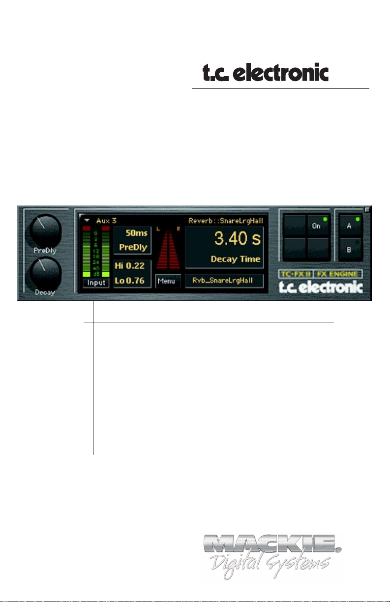
TC FX II
Renowned M2000 Reverb Algorithms
Plug-in for Mackie Digital Mixers
®
™
Page 2
Iconography
This icon identifies a description of how to
perform an action with the mouse.
This icon identifies a description of how to
perform an action from the console.
This icon will lead you to some further
explanations of features and practical tips.
This icon marks information which is very
important, so please make sure you have a read.
This icon does not appear in this guide.
“Mackie” and the “Running Man” figure are trademarks or
registered trademarks of Mackie Designs Inc. All other brand
names mentioned are trademarks or registered trademarks of
their respective holders, and are hereby acknowledged.
Part No. 820-246-00 Rev. B 02/2001
¤
2
© 2001 Mackie Designs Inc. All Rights Reserved.
TC FX II
Page 3

Contents
Introduction ----------------------------------------4
About TC Electronic --------------------------------------------4
About the D8B UFX Card -------------------------------------- 5
About TC FX II --------------------------------------------------- 5
Let’s Get Started ---------------------------------- 6
Requirements----------------------------------------------------6
Authorizing the Plug-in----------------------------------------6
Unlock Procedure ----------------------------------------------- 7
Configuring the Plug-in --------------------------------------- 8
Using the TC FX II Plug-in ---------------------- 10
Front Panel Overview ---------------------------------------- 10
Saving, Loading and Resetting a Preset -------------------12
Automation and Snapshot Control ---------- 14
FX Routing -----------------------------------------15
Note: Any future revisions of this guide will be available for
viewing and downloading from our website: www.mackie.com.
User’s Guide
3
Page 4

Introduction
TC Electronic’s™ TC FX II™ is one of the exciting new family of
24-bit plug-ins for the D8B, specifically designed for the new
Mackie Universal Effects (UFX) card.
The UFX comes bundled with Mackie Real Time OS 3.0,
TC FX II (Level I), and Mackie’s Mono Delay.
About TC Electronic
TC Electronic was founded in 1976 with the objective of
developing, producing, and marketing first class audio products.
Now they're the undisputed industry leader in digital effects and
reverb technology.
TC's development team encompasses not only the R&D
department at their main office in Risskov/Denmark, but also an
increasing number of the very best audio software engineers
around the world. Their Hamburg, Germany satellite company,
TC/Works, is dedicated to creating quality products for computer
workstations.
TC users include top artists, world class recording studios, TV
and Radio stations, theaters, operas and other installations and
public address companies. At the 1999 TEC Awards, TC
Electronic was nominated for five, and walked away with three including the M3000 Studio Reverb Processor in the category of
"Signal Processing Hardware" and the TC/Works Master X in
the "Signal Processing Software" category.
Twenty-four years after its inception, TC continues to produce
some of the most precise and gloriously musical effects ever to
come off a chip.
4
TC FX II
Page 5
About the D8B UFX Card
The UFX card provides robust processing power for computationheavy plug-ins. The UFX uses a 4-in/4-out architecture, which
means it can support four mono, two mono and one stereo, or
two stereo sends simultaneously. Up to four UFX cards can be
installed in the D8B, allowing up to sixteen simultaneous singlechannel effects, eight stereo plug-ins, or combinations thereof.
Note: It is recommended that you increase the D8B’s memory if you install
more than one UFX card. Memory upgrade instructions are supplied with each
card.
About TC FX II
The new TC FX II Series for the Digital 8•Bus furthers TC’s
reputation for the finest effects in the world. It provides plug-in
versions of many of their most popular effects algorithms,
including the Reverb-1 and Reverb-2 algorithms from the
renowned TC Electronic M2000, and many TC factory presets.
This version of TC FX II is TC Level I. It is for demonstration
purposes, and we hope it will whet your appetite towards the
higher TC FX II levels.
User’s Guide
5
Page 6
Let’s Get Started
Requirements
• One or more Mackie UFX cards
• Mackie Real Time OS 3.0 Software
• Plug-in Software
We will assume you have successfully installed a Mackie UFX
card and Mackie Real Time OS 3.0 software upgrade. If you have
encountered problems with the installation of hardware or
software please see their associated user guides or contact
Mackie support (www.mackie.com).
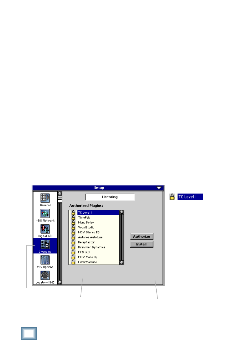
Authorizing the Plug-in
If you have D8B v 3.0 b186 or greater, the plug-in is already
installed on the D8B hard drive, however an authorized unlock
code must be entered to unlock the plug-in for normal operation.
In the windows and menus, the plug-in is shown as TC Level I.
LICENSING
6
1234-5167-89D1
D8B Electronic Serial Number (ESN)
TC FX II
An Unlocked
Plug-in
AUTHORIZE
D8B SETUP screen’s
LICENSING window
Page 7

Unlock Procedure
1. Locate your D8B’s Electronic Serial Number (ESN). This
is displayed at the bottom of the Licensing window
which is accessed from the Setup screen. The 12 digit
ESN is made from numbers 0–9 and letters A–F. It is
unique to the D8B processor, and is not the serial
number label on the rear of the control surface or CPU
chassis.
2. You will also need your plug-in’s serial number which is
1111 1111 1111.
3. To obtain the unlock code, have the ESN and plug-in
serial number ready. Then you have two options:
• Log on to the Mackie plug-in authorization web page:
(http://www.mackie.com/d8bauthorize.htm)
or
• Telephone Mackie Tech Support at 800-258-6883.
4. When you have obtained an unlock code, open the D8B
Setup window, and click Licensing.
5. With your plug-in highlighted in the Licensing window,
click Authorize, and enter your unlock code in the
UNLOCK CODE box. Click Enter, and enjoy your newly
expanded console.
User’s Guide
7
Page 8

Configuring the Plug-in
After booting the D8B you must assign the plug-in to a UFX
card. See “FX Routing” on page 15 for more details.
Assign the Plug-in to a UFX card
1. Click the Plugins menu and select
Plugins, or Ctrl+P
on the keyboard.
2. In the Plugin
Configuration
window, locate the
card slot that
contains the UFX
card you wish to
assign to.
3. In the Mode column,
click the Mono/
Stereo toggle button
and set it to Stereo.
4. In the Plugin column,
select TC Level I from
the stereo plug-in drop
down menu.
Note:Note:
Note: A Plug-in can also be loaded from the Setup section on the console.
Note:Note:
8
TC FX II
Page 9

Assign an Input Source to the Plug-in
• Click the plug-in’s INPUT menu button to select an input
source. In the example below, we have chosen the Aux 5
Bus as the input to the plug-in installed in Slot 5.
When a plug-in is fed from an
aux bus, its output appears
on the FX Return channels
(faders in the EFFECTS
bank). The return channel is
determined by the slot
number and whether the
effect output is mono or
stereo. For example, a reverb
with a mono input and stereo
output that is installed in Slot
5 has its outputs on FX 5 and
FX 6. Note: The default state
for all FX channels is MUTE.
You won’t hear the effect
until you unmute its FX
return channel(s).
A plug-in can also receive its input from a channel pre- or postDSP insert or the main stereo left and right Bus. When a plug-in
is inserted “in line” in this manner, its output is routed directly
back into the channel. See “FX Routing” on page 15 for more
details.
Removing the Plug-in
1. Select none from the associated plug-in
drop-down assignment menu.
2. Click OK in the Alert dialog box.
Note:Note:
Note: A plug-in can also be deleted
Note:Note:
from the Setup section on the console.
User’s Guide
9
Page 10

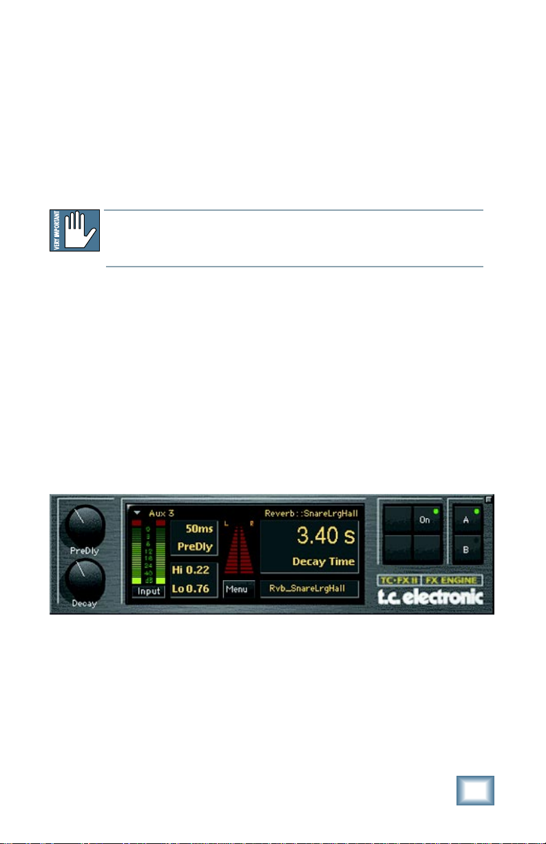
Using the TC FX II
Front Panel Overview
Pre-Delay
Control
Input Assignment
and Dropdown Button
Pre-Delay Display
(mouse active)
Preset
Algorithm
Effect
Bypass
Close
Display
Meter Displays
(In/Out)
Decay Time
Control
High/Low Freq Decay (mouse active)
Input/Output Meter
Toggle Button
Preset Selection
& Display
Menu
Button
Decay Time
Display (mouse
active)
Pre-Delay Control and Display
Pre-Delay is the subtle delaying of the reverb itself so that the dry
signal more easily stands out from the reverb. It can give the
impression of a larger sound, especially with instruments such as
percussion. The Pre-Delay parameter can also be controlled by the
mouse in the Pre-Delay display. Ranges from 0ms to 200ms.
Note: When the input assignment is from a channel insert or L/R
mix rather than an Aux, the Pre-Delay control changes to a Mix control, allowing adjustment of the amount of reverberation added to
the direct channel signal. In this mode, pre-delay can be adjusted by
dragging the mouse on the pre-delay value.
Decay Control and Display
The Reverb Decay determines how long the reverb will sound
before it can no longer be heard. The Decay parameter can also
be controlled by the mouse in the Decay display. Ranges from
200ms to 20S.
Input Assignment Button
Assign TC FX II inputs from any of the D8B’s
pre, post, mix L/R or auxiliary channels.
Memory A/B
Buttons
10
Note:Note:
Note: The Input Source can be set from either the
Note:Note:
plug-in GUI or the Patch Configuration Window.
TC FX II
Page 11

Input/Output Meter Display and Toggle Button
This button toggles from Input to Output. Meters range from
–40 dB to 0 dB. Note: The meters above the Menu button are
inactive in this version.
Hi/Low Frequency Decay Control and Display
These two parameters allow the decay time to be set separately
for both low and high frequencies as a multiplication factor
value. This means you have control over the tonal shape of the
reverb itself, being able to make the high frequencies dissipate
faster if the reverb is too bright, and make the lows dissipate
faster if the reverb is too boomy. This allows you to simulate
different surfaces of an acoustic environment with softer
surfaces having more high frequency decay and smaller
enclosures having more low frequency decay. The scale for these
controls is a multiplication factor ranging from 0.02 to 2.5 times
the nominal delay time.
Menu Button
The drop-down menu button will enable familiar functions such
as undo, redo, load, save, reset, cut, copy, and paste.
Preset Selection and Display
Select from Factory or Users presets
by clicking in the preset name
display. The displayed Preset
Algorithm which makes up the
Factory preset is not editable, but can be used as a
base for making and saving your own User presets.
Effect Bypass
Enables or disables the TC FX II.
Close Display
Clicking this button will close the TC FX II display while still
keeping the plug-in enabled.
A/B Memory Buttons
Memory A and Memory B are two separate storage banks that
let you temporarily store set-ups. This is handy for quickly
referencing and comparing sounds while you are creating edits.
User’s Guide
11
Page 12

Saving, Loading and Resetting a Preset
TC FX II settings can be saved and recalled from the
hard drive. You can save and load files from either
Memory A or Memory B.
To Save a Preset:
1. Click and hold the Menu button.
2. Select Save to overwrite the file
currently opened.
3. Select Save TC Level I As to save to
a new file name. The Save Preset
File As dialog box appears.
4. A default name for the preset is
automatically displayed, such as
Preset#1. If you want to rename it,
simply type in the name you want,
using up to 32 characters.
12
A new sub folder can
be easily created to
help organize custom
patches.
5. Select INTERNAL (default hard drive) or FLOPPY.
6. Click Save to complete the operation.
TC FX II
Page 13

To Load a Preset:
1. Click Memory A or Memory B to choose the
memory location from which to load the file.
2. Click and hold the Menu button.
3. Select Load TC Level I to open a
file. The Load Preset File dialog box
appears.
4. Click INTERNAL if the file is on the internal drive, or
click FLOPPY if the file is on a floppy disk.
5. Select the preset you want to load.
6. Click Open to load the selected preset.
Other Menu Items:
Reset: Loads the previous patch.
Cut: The current settings are temporarily stored in the
clipboard memory in case you want to paste them to a
new preset. The plug-in also reverts to its default
state (it is reset).
Copy: The current settings are temporarily stored in the
clipboard memory in case you want to paste them to a
new preset.
Paste: The current settings are replaced with the setting in
the clipboard memory.
User’s Guide
13
Page 14

Automation and Snapshot Control
Dynamic Real Time
To write automation on a loaded Plug-in:
1. Engage AUTO TOUCH.
2. Engage ALL, disengage
BYPASS, and send
timecode to the console –
the POSITION readout will change to show TC is being
received.
3. Move a parameter or recall a patch (user or factory
preset).
Subsequent edits to any recorded automation moves may be
performed in the Mix Editor. Enable the channel view by clicking
the Channel View button, then choose the plug-in you wish to
view from the page drop-down
menu. This displays a list of
available channel and plug-in
automation tracks on a
parameter basis.
Note:Note:
Note: Parameters can be controlled from either the GUI Plug-in graphic param-
Note:Note:
eters (using a mouse to modify the parameters) or via the VFD V-Pots and
SELECT buttons (with the Plug-in parameters called up on the VFD readout).
On The Console
Dynamic Off-line
To write a snapshot on a loaded plug-in:
♦
Use the Event Automation Track, available under the
Window Menu as ‘Event Track’, to load plug-in user
(previously stored) or factory preset patches, at a
specific time during automation playback.
General Note:General Note:
General Note:
General Note:General Note:
Plug-in settings are recalled as part of a console Snapshot, but may also be recalled as Presets (patches). If you are recalling snapshots and presets, be aware
that one may override the other.
14
TC FX II
Page 15

FX Routing
The Plug-in Configuration Window
Input Source As-
Card Slot Column
Plug-in
display toggle
Input Channel
Assignment Dropdown Menu Button
Card A
Card B
Card C
Card D (no
card installed)
signment Column
Stereo Plug-in Routing
If the plug-in has a stereo input as well as stereo output,
typically it will be fed from two aux buses and returned to a pair
of FX return channels. In the diagram below, Aux 1 and Aux 2
feed the plug-in in stereo, and its output is returned to FX 1 and
FX 2. If the plug-in has a stereo input, it is permissible to send
the same aux to both inputs.
Plug-in Assignment Column
Close Window
Stereo/Mono
Mode Column
Stereo/Mono
Toggle Button
FX Channels 1&2
(channels 49&50)
Stereo Input
(Aux 1 & 2)
Note:Note:
Note: When an FX Channel Assignment
Note:Note:
Stereo Plug-in
light is lit, the assigned plug-in is open and
visible on the main mixer screen.
User’s Guide
15
Page 16

Inserting a Plug-in into a Channel
A pre- or post-DSP channel insert can also be used as the input
source for a plug-in. When a channel insert point is selected, the
plug-in output returns to the channel. The FX return path is
disconnected, although the plug-in output is still displayed on
the FX return channel meter.
A plug-in channel insert assignment can be made from the
Plugin Configuration window, or from a drop-down menu from
the mixer screen.
Plug-in Configuration Window
Post-DSP Drop-down
Pre-DSP Drop-down
This assignment can also be made from the control surface and
VFD by holding in the desired channel’s SELECT button for two
seconds, then paging over to Plug Pre or Plug Post, selecting
the input source, then selecting the desired plug-in slot from the
follow-on menu.
16
TC FX II
Page 17

Using an Aux Send with a Plug-in
♦
Click on the associated INPUT menu button and select
an aux input source. In the example below, we have
chosen the Aux 5 Bus.
Send the Input Signal to the Aux Bus
1. Send a signal to a D8B mixer input channel (MIC/LINE
or TAPE IN).
2. Assign the input channel V-Pot/GUI
Control Pot to an aux send. We have
chosen AUX 5 according to the example
above.
3. Use the AUX 5 control to
adjust the input level to the
plug-in.
Remember to select an aux send before using the V-pot or GUI
Control Pot on the mixer input channel (MIC/LINE or TAPE IN).
User’s Guide
GUI Control
Pot Assigned
to AUX 5
17
Page 18

You will see the plug-in’s input meter become active as you raise
the mixer input channel’s aux send.
Set the plug-in input/output signal levels as you would with any
effect, so the meter reaches its upper-most range every so often
(always trust your ears first). This can be accomplished from the
console or GUI.
Pre-Fader and Post-Fader Auxiliary Sends
Normally, effect sends are post-fader, so the signal sent to the
effect follows the program level in the mix. Occasionally you
may wish to feed an effect from a pre-fader source so that the
signal level from the Aux control is independent of the channel
fader position. Aux sends are selectable pre- or post-fader
globally (all Aux 1’s for instance) from the Mix Options screen in
the Setup window, or individually on a channel-by-channel basis
either from the channel strip or the Fat Channel.
In the channel strip, Alt-click the Aux Send level
indicator to toggle between pre-and post-fader operation.
Post-fader is indicated by a red bar, pre-fader is indicated
by a yellow bar.
In the Fat Channel,
clicking on the small
indicators below the
Aux knobs toggles
between pre- and postfader operation. Yellow
indicates pre-fader,
post-fader is indicated
by the background
color.
Channel Strip
18
Fat Channel
TC FX II
Page 19

The FX Return Channel
♦
Switch the D8B Bank Select to
EFFECTS (49-72) and bring up
faders one and two (channels 49 and
50). You will also see meter activity
associated with these channels.
FX Channels 1&2
(channels 49&50)
Stereo Plug-in
The Plug button
toggles between
Windows menu
buttons and FX
buttons (lower
left on the D8B
mixer screen).
Plug-ins button opens the Patch
Configuration window (or
Ctrl+P
on the keyboard)
Here the Delay Factor plug-in is
selected for display.
User’s Guide
19
Page 20

®
™
©2001 Mackie Designs Inc. and TC Electronic. All Rights Reserved.
Part No. 820-246-00 Rev. B 02/2001
 Loading...