

Page 1
OL
–3
–6
–9
–20
–3
–6
–9
–20
SIG
OL
SIG
CH
1
30
28
26
20
22
18
2416
14
8
0
0
1.23v (+4dBu)
SENSITIVITY
GAIN/dB
CH
2
PROTECT
COLD HOT
SHORT
TEMP STATUS
INTERNAL STATUS
CH
1
CH
2
CH
1& 2
ON
OFF
POWER
3v
2v
1v
30
28
26
20
22
18
2416
14
8
0
0
1.23v (+4dBu)
SENSITIVITY
GAIN/dB
3v
2v
1v
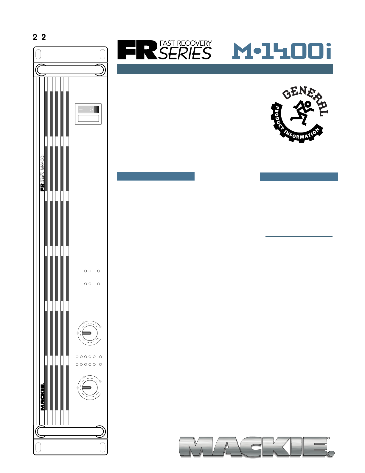
PROFESSIONAL POWER AMPLIFIER
FULL SYMMETR Y DUAL DIFFERENTIAL HIGH CURRENT DESIGN
2/25/98
TM
F AST REC O VERY SERIES HIGH CURRENT POWER AMPLIFIER
The world is full of amplifiers that do one thing –
amplify audio signals. But at Mackie Designs, we’ve
always put out the extra effort to provide more quality and more features than our competitors while
maintaining a comparable (or lower) price.
The FR Series™ power amplifiers are designed to
perform reliably under the most adverse conditions,
and we’ve added a bundle of extra features, so you
don’t have to put out the extra bucks to buy a
bunch of add-ons or plug-ins to make your sound
system do what you want it to do.
®
with Architects and
Engineers Specifications
FEATURES
■ Fast Recovery design
for improved tran-
sient response and
recovery from clip-
ping
■ Rack-mountable (2U)
with rear support
rails for extra support
■ Separate left and
right detented gain
controls, calibrated in
both dB and volts
■ Balanced XLR and
1/4" TRS input jacks
■ Balanced XLR thru
jacks
■ Heavy-duty binding
post output jacks in
parallel with 1/4" T S
output jacks
■ 6 LED metering
including Signal
Present and Overload
■ Four levels of protec-
tion circuitry
1) Automatic turn-on
delay to prevent
thumps and pops
from reaching your
speakers
2) Short-circuit
protection with
separate L/R indicating LEDs
3) Thermal protection
with combined CH1
and CH2 Cold and Hot
indicating LEDs
4) SCR Crowbar DC
offset protection
■ Low-cut filter with
variable frequency
control (Off – 170Hz)
■ Infrasonic1 stabiliza-
tion eliminates ultralow-frequency noise
caused by microphone handling,
stage rumble
■ Constant directivity
horn compensation
with variable highfrequency boost
control (2kHz to
6kHz)
■ Amp Mode switch for
Stereo, Mono, or
Bridge modes
■ Limiter to eliminate
clipping in both
channels
1
a.k.a. Subsonic.
MORE INFORMATION
CHECK OUT OUR
WEBSITE
WWW.MACKIE.COM
■
“IN YOUR F A CE”
ALL PRODUCT
BROCHURE
■ Subwoofer mode
switch with dualfrequency select
(63Hz/125Hz)
■ T-Design Constant
Gradient Cooling
T unnel uses two
short tunnels instead
of one long tunnel
for improved cooling
efficiency and output
device reliability
■ Dual-speed cooling
fan
■ Toroidal transformer
for reduced EMI
emissions
Page 2
CH 1
BALANCED
LINE INPUT
(TRS)
CH 1
BALANCED
LINE INPUT
(XLR-F)
LIMITER
LIMITER
ON
OFF
LOW CUT
FILTER
LOW PASS
FILTER
(SUBWOOFER)
+
–
80 VDC
+
–
90 VDC
TOROIDAL P OWER
TRANSFORMER
LAMP
FUSE
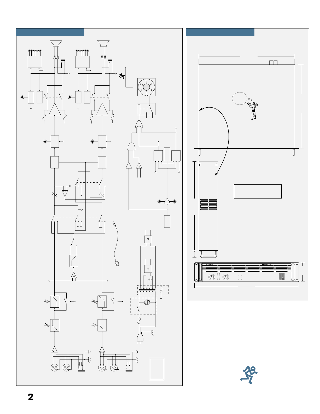
MACKIE DESIGNS
M•1400i
BLOCK DIAGRAM
(#022598DF)
FREQ
CD EQ
FREQ
OUTPUT
APPLICATION
SWITCH
AMP
MODE
SWITCH
63 Hz
125 Hz
FREQ
TO
LIMITER
ON
OFF
LOW CUT
FILTER
FREQ
CD EQ
FREQ
CH 1
GAIN
STEREO
MONO
BRIDGE
CH 2
GAIN
INVERTING
UNITY GAIN
AMPLIFIER
ON
OFF
SUB
ON
OFF
SUB
NC
NC
NC
MUTE
CH 1
PROTECT
LED
CH 1
SHORT
LED
MUTE
CH 2
PROTECT
LED
POWER
AMPLIFIER
FUSE
–80VDC
FUSE
+80VDC
DC OFFSET
DETECT
SHORT
DETECT
METER
DRIVE
POWER
AMPLIFIER
FUSE
–80VDC
FUSE
+80VDC
DC OFFSET
DETECT
TO CH 1
MUTE
OL
–3
–6
–9
–20
SIG
CH 1
SIG
CH 2
SHORT
LED
SHORT
DETECT
METER
DRIVE
TO CH 2
MUTE
TO CH 1
MUTE
TO CH 2
MUTE
OL
–3
–6
–9
–20
SIG
CH 2
SIG
SIG
(TO CH 1
METER DRIVE)
SIG
(TO CH 2
METER DRIVE)
PD's LEASH
HOT
LED
COLD
LED
TEMP
SENSOR
(ON HEATSINK)
FROM CH 1
SHORT DETECT
FROM CH 2
SHORT DETECT
CH 1
MUTE
CONTROL
CH 2
MUTE
CONTROL
4 SEC DELAY
(TURN-ON)
CH 1 AMP OUT
CH 2 AMP OUT
PROGRAM
DETECT
AND
OR
60ºC
DETECTOR
FAN
SPEED
CONTROL
HI DCV
LO DCV
CH 1
MUTE
CH 2
MUTE
POWER
SWITCH
TO CH 1
AND CH 2
MUTE
THERMAL
PROTECT
THRU
(XLR-M)
CH 2
BALANCED
LINE INPUT
(TRS)
CH 2
BALANCED
LINE INPUT
(XLR-F)
THRU
(XLR-M)
80ºC MUTE
55ºC UNMUTE
FAN
TO HUSKY
STADIUM
CH 1
SPEAKER
OUT
CH 2
SPEAKER
OUT
OL
–3
–6
–9
–20
–3
–6
–9
–20
SIGOLSIG
CH
1
30
28
26
20
22
18
2416
14
8
0
0
1.23v (+4dBu)
SENSITIVITY
GAIN/dB
CH
2
PROTECT
COLD HOT
SHORT
TEMP STATUS
INTERNAL STATUS
CH
1
CH
2
CH
1&2
ON
OFF
POWER
3v
2v
1v
30
28
26
20
22
18
2416
14
8
0
0
1.23v (+4dBu)
SENSITIVITY
GAIN/dB
3v
2v
1v
PROFESSIONAL POWER AMPLIFIER
FULL SYMMETRY DUAL DIFFERENTIAL HIGH CURRENT DESIGN
19.00" (48.3cm)
17.25" (43.8cm)
15.25" (38.7cm)
3.50"
(8.9cm)
2U
16.25" (41.3cm)
M•1400i
WEIGHT
36 lbs.
(16.3 kg)
1.25"
(3.2cm)
BLOCK DIAGRAM
DIMENSIONS
M•1400i
DIMENSIONS
®
Page 3

SPECIFICATIONS
CHANNEL
2
1
CHANNEL
CH
1
CH
2
SPEAKER OUTPUTS
+
––
+
63Hz
125Hz
CONSTANT DIRECTIVITY
HORN EQ /AIR EQ
CONSTANT DIRECTIVITY
HORN EQ /AIR EQ
INPUT
THRUTHRU
INPUT
AMP MODE
FREQUENCY
4.5 k Hz
ON
6k Hz
2k Hz
MONO
B
R
I
D
G
E
LIMITER
(CH1 & CH2)
OFF
FULL
RANGE
SUB
WOOFER
LOW CUT
FILTER
LOW CUT
FILTER
OUTPUT APPLICATION
BALANCED
OR
UNBALANCED
BALANCED
OR
UNBALANCED
AIR EQ
ON
/ BRIDGE / MONO
170 Hz
OFF
4.5k Hz
6k Hz
2k Hz
AIR EQ
+
–
170 Hz
100 Hz
OFF
STAGE
MONITOR
100 Hz
STAGE
MONITOR
OFF
TYPICAL
ON
OFF
TYPICAL
TYPICAL
35 Hz
TYPICAL
35 Hz
STEREO
TYPICAL
STEREO
TYPICAL
AIR EQ
AIR EQ
SERIAL NUMBER
MANUFACTURING DATE
RISK OF ELECTRIC SHOCK
DO NOT OPEN
REPLACE WITH THE SAME TYPE FUSE AND RATING.
DISCONNECT SUPPLY CORD BEFORE CHANGING FUSE
UTILISE UN FUSIBLE DE RECHANGE DE MÊME TYPE.
DEBRANCHER AVANT DE REMPLACER LE FUSIBLE
WARNING:
TO REDUCE THE RISK OF FIRE OR ELECTRIC SHOCK, DO NOT
EXPOSE THIS EQUIPMENT TO RAIN OR MOISTURE. DO NOT REMOVE COVER.
NO USER SERVICEABLE PARTS INSIDE. REFER SERVICING TO QUALIFIED PERSONNEL.
CAUTION
AVIS:
RISQUE DE CHOC ELECTRIQUE — NE PAS OUVRIR
MONO
BRIDGE
120 VAC 60 Hz
1500 WATTS
CONCEIVED, DESIGNED, AND MANUFACTURED BY MACKIE DESIGNS INC • WOODINVILLE • WA • 98072 • USA • MADE IN USA • FABRIQUE AU USA •
PATENTS PENDING
COPYRIGHT
©
1997 • THE FOLLOWING ARE TRADEMARKS AND/OR REGISTERED TRADEMARKS OF MACKIE DESIGN INC.: "MACKIE", FR SERIES, AND THE "RUNNING M
AN" FIGURE
(MONO BRIDGE)
1400 WATTS
4 OHM LOAD MIN.
700 WATTS CH
2 OHM LOAD MIN.
Continuous Average Output
Power, both channels
driven:
250 watts per channel into
8 ohms from 20Hz to 20kHz,
with no more than 0.01 2% THD
425 watts per channel into
4 ohms from 20Hz to 20kHz,
with no more than 0.025% THD
630 watts per channel into
2 ohms from 20Hz to 20kHz,
with no more than 0.050% THD
Bridged mono operation:
850 watts into 8 ohms from
20Hz to 20kHz, with no more
than 0.025% THD
1260 watts into 4 ohms from
20Hz to 20kHz, with no more
than 0.050% THD
Maximum Power at 1% THD
(per IHF-A-202):
300 watts per channel into 8Ω
500 watts per channel into 4Ω
700 watts per channel into 2Ω
1000 watts into 8Ω bridged
1400 watts into 4Ω bridged
Power Bandwidth:
20Hz to 70kHz (+0, –3dB)
Frequency Response:
20Hz to 40kHz (+0, –1dB)
10Hz to 7 0kHz (+0, –3dB)
Distortion:
THD, SMPTE IMD, TIM
< 0.025%@8Ω
< 0.050%@4Ω
< 0.150%@2Ω
Signal to Noise Ratio:
> 107dB below rated
power into 4 ohms
Channel Separation:
> 80dB@1kHz
Damping Factor:
> 350 from 0 to 400Hz
Input Impedance:
20kΩ balanced bridging
Input Sensitivity:
1.23 volts (+4dBu) for
rated power into 4 ohms
Gain:
30.25dB (32.5V/V)
Maximum Input Level:
9.75 volts (+22dBu)
Rise Time:
< 4.4µs
Slew Rate:
Voltage Slew Rate
> 50V/µs
> 100V/µs bridged
Current Slew Rate
> 32A/µs at 2Ω
CMRR:
> 40dB, 20Hz to 20kHz
Transient Recovery:
< 1µs for 20dB overdrive @
1kHz
High Frequency Overload
and Latching:
No latch up at any frequency
or level
Variable Low-Cut Filter:
10Hz (Off) to 170Hz,
2nd Order Bessel
Subwoofer Low-Pass Filter:
Switched: 63Hz/125Hz,
3rd Order Bessel
Constant Directivity High
Frequency Boost:
2kHz to 6kHz (+3dB points)
6dB/octave high-frequency
shelving filter, (shelving occurs
at approximately 30kHz)
Turn On Delay:
3 seconds
Limiter Section:
Channel independent
complementary positive and
negative peak detecting
Indicators:
Six meter LEDs per channel:
SIG (Signal Present),
–20, –9, –6, –3, OL (Overload)
CH 1 & 2
PROTECT LEDs
SHORT LEDs
TEMP STA TUS
COLD, HO T LEDs
Power Consumption:
65 watts at idle 0.9A
550 watts with musical
program fully loaded 6.7A
(4Ω per side, or 8Ω bridged)
900 watts with musical
program fully loaded 10.5A
(2Ω per side, or 4Ω bridged)
850 watts at full power into 8Ω
(cont. sine wave) 9.6A
1500 watts at full power into 4Ω
(cont. sine wave) 15.6A
2500 watts at full power into 2Ω
(cont. sine wave) 24.8A
AC Line Power:
120VAC, 60Hz
AC Drop-out V oltage:
At approximately 50% of
rated line voltage
Physical:
Height: 2U = 3.5" (89mm)
Width: 19.0" (483mm)
Depth: 15.25" (387mm)
Handle Depth:
1.25" (32mm)
Overall Depth:
16.25" (413mm)
Weight: 36 lbs (16.3kg)
Mackie Designs Inc. is engaged in a continuous
pr o gr a m o f p r o d u c t e va l u a t i o n and improvement
and reserves the right to change product
specifications at any time without notice.
The following are trademarks or registered
trademarks of Mackie Designs Inc.: The Mackie
logo, the Running Man, and FR Series.
Part No. 091-154-00 2/98
1998 Mackie Designs Inc. All Rights Reserved.
©
Printed in Woodinville USA.
3
Page 4

ARCHITECTS AND ENGINEERS SPECIFICATIONS
1. GENERAL. The amplifier
shall have a free-standing
frame with front and rear
brackets for rack-mounting,
and supplied with four
resilient feet suitable for tabletop placement. The amplifier
shall be capable of two-channel
operation, with a switch to
place the amplifier into singlechannel operation by bridging
the outputs of the two channels.
2. POWER OUTPUT. The
power amplifier, being of two
channels, shall deliver a rated
continuous average sine wave
power output over a 20Hz to
20kHz bandwidth of 250 watts
RMS into 8 ohms per channel,
425 watts into 4 ohms, and
630 watts into 2 ohms with
both channels operating, with
no more than 0.05% total
harmonic distortion. In singlechannel operation it shall
deliver 850 watts RMS into
8 ohms and 1260 watts into
4 ohms, with no more than
0.05% total harmonic
distortion.
The power amplifier shall
deliver a maximum continuous average sine wave power
output over a 20Hz to 20kHz
bandwidth of 300 watts RMS
into 8 ohms per channel, 500
watts into 4 ohms, and 700
watts into 2 ohms with both
channels operating, with no
more than 1% total harmonic
distortion. In single-channel
operation it shall deliver 1000
watts RMS into 8 ohms and
1400 watts into 4 ohms, with
no more than 1% total
harmonic distortion.
3. POWER SUPPLIES. All
necessary operating voltages
for the amplifier shall be
provided by an internal power
supply. A master power switch
shall be located on the front
panel along with a green
power-indicating light.
4. INPUT CHANNEL
CONNECTIONS. Each
monaural input channel
shall have a n electronically
balanced line-level input,
presenting no less than a 20k
ohm impedance to the source.
Each input shall have an input
sensitivity of +4dBu, requiring
no more than 1.23V rms to be
driven to rated output into a
4 ohm load. The input
connector shall appear on the
rear panel as a female XLR-3
type connector. In addition,
each monaural input channel
shall have a parallel 1/4" TRS
phone jack and a male XLR-3
type connector, which can be
used as inputs or “thru” jacks
for daisy-chaining the input
signal to another amplifier.
Pin 2 of the XLR connectors,
and the tip of the 1/4" TRS
phone jack, shall be noninverting.
5. INPUT CHANNEL LEVEL
CONTROLS. Each monaural
input channel shall be equipped
with a gain control appearing
on the front panel, each
having 40 detent positions,
and calibrated in dB and volts.
6. FRONT PANEL INDICATORS. Each channel shall
have an associated six-segment
LED meter appearing on the
front panel, capable of
displaying signal present,
–20dB, –9dB, –6dB, –3dB,
and overload. Each channel
shall have internal status LEDs
appearing on the front panel
to indicate activation of protect
mode and short-circuit
protection. Two temperature
status LEDs shall appear on
the front panel, one to
indicate normal operation
(COLD) and one to indicate
thermal protection (HOT).
7. PROTECTION FEATURES.
The amplifier shall provide
delayed activation of the
outputs at turn-on. Each
channel shall have a shortcircuit protection circuit for
detecting excessive current
flow at the output that, when
activated, mutes the output
for four seconds. The shortcircuit protection shall
continuously cycle on and off
until the shorted condition is
remedied. The amplifier shall
have a thermal protection
circuit to protect the power
devices from over-temperature
operation. The circuit shall
activate when the internal
temperature crosses the safeoperating threshold and,
T oll-Free 800/258-6883 • FAX 425/ 48 7-4337 • E-mail: sales@mackie.com
®
when activated, mute the
outputs until the internal
temperature cools to a safeoperating temperature, at
which time the amplifier shall
resume normal operation. The
amplifier shall have a fan to
cool the heat-producing
internal components, drawing
cool air in from the front, and
exhuasting warm air out
through both sides. The fan
shall operate at two speeds,
the speed being determined
by the internal temperature
and the signal level present at
the output. The amplifier shall
have an SCR crowbar circuit to
protect the speakers against a
catastrophic amplifier failure.
The circuit shall activate in the
presence of continuous DC at
the speaker outputs, and shall
shut the amplifier down by
turning off the high-voltage
rails.
8. OUTPUT CONNECTIONS.
Each channel shall have a
heavy-duty 5-way binding
post speaker output connector appearing on the rear
panel, with 3/4" spacing for
accommodating standard
double banana plugs as well
as spade lugs or bare wires.
Each channel shall have a 1/4"
TS phone speaker output jack
appearing on the rear panel in
parallel with the binding post
output.
9. AMP MODES. The
amplifier shall have a threeway switch appearing on the
rear panel for selecting the
mode of operation, which
shall include stereo (two
channels in, two channels
out), mono (one channel in,
two channels out), and bridge
(one channel in, one channel
out, bridged between both
speaker outputs).
10. OUTPUT APPLICATION.
The amplifier shall have a
three-way switch appearing
on the rear panel for selecting
between limiter on, limiter off,
and subwoofer mode. The
defeatable electronic limiter
circuit shall sense the onset of
clipping and shall limit the
input signal and thereby
prevent the output from
clipping. The amplifier shall
have a two-way switch
appearing on the rear panel
for selecting between a 63Hz
and 125Hz low-pass cutoff
frequency when subwoofer
mode is selected.
11. LOW-CUT FILTER. Each
channel shall have a low-cut
filter with a variable frequency
control appearing on the rear
panel covering a range of
10Hz (OFF) to 170Hz.
12. CONST ANT DIRECTIVITY
HORN EQ. Each channel shall
have a two-way switch
appearing on the rear panel
for selecting a constant
directivity horn equalization
circuit. When selected, this
circuit shall provide a 6dB per
octave high frequency boost.
The EQ shall have a variable
frequency control appearing
on the rear panel covering a
range of 2kHz to 6kHz. The
6kHz position shall be called
AIR.
13. PHYSICAL CONFIGURATION. The amplifier shall be
rack-mountable with rear
support rails for extra support,
and shall have a steel chassis
frame painted grey-black. The
amplifier shall be 19" wide
(483mm), 3.5" (2U) tall
(89mm), and 15.25" deep
(387mm), and shall weigh 3 6
pounds (16.3kg).
14. DESIGNATION. The
power amplifier shall be a
Mackie Designs M•1400i.
MACKIE DESIGNS INCORPORATED
16220 Wood-Red Rd. NE
Woodinville • WA • 98072 • USA
www.mackie.com
4
 Loading...