

Page 1
MORE INFORMATION
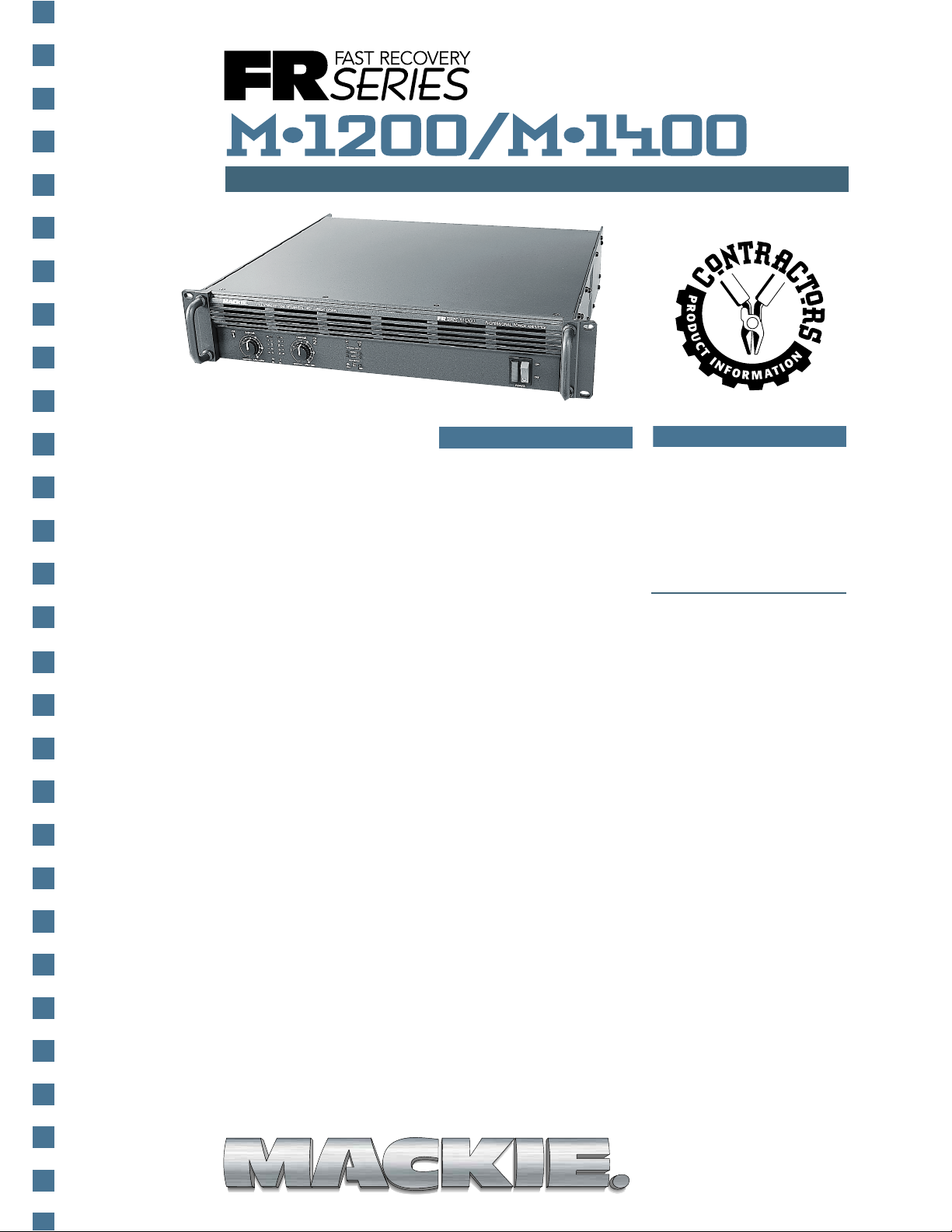
TM
F A S T REC O VER Y SERIES HIGH CURRENT POWER AMPLIFIERS
The world is full of amplifiers
that do one thing – amplify
audio signals. But at Mackie
Designs, we’ve always put
out the extra effort to provide
more quality and more
features than our competitors
while maintaining a comparable (or lower) price.
The FR Series™ power
amplifiers are designed to
perform reliably under the
most adverse conditions,
and we’ve added a bundle
of extra features, so you
don’t have to put out the
extra bucks to buy a bunch
of add-ons or plug-ins to
make your sound system
do what you want it to do.
Meticulous Detail
Perhaps the most important aspect of the FR Series
amplifiers is the attention
to detail in the design of
the electronic architecture.
We have incorporated a
number of unique properties
including Fast Recovery,
sustained high-current output
capability, high voltage and
current slew rate, and defeatable clipping eliminator, to
ensure that the output of
the amplifier is virtually
distortion-free.
FEATURES
■ Fast Recovery design
for improved transient
response and recovery
from clipping
■ Rack-mountable (2U)
with rear support rails
for extra support
■ Separate left and right
detented gain controls,
calibrated in both dB
and volts
■ Balanced XLR and 1/4"
TRS input jacks
■ Balanced XLR thru jacks
■ Heavy-duty binding post
output jacks in parallel
with:
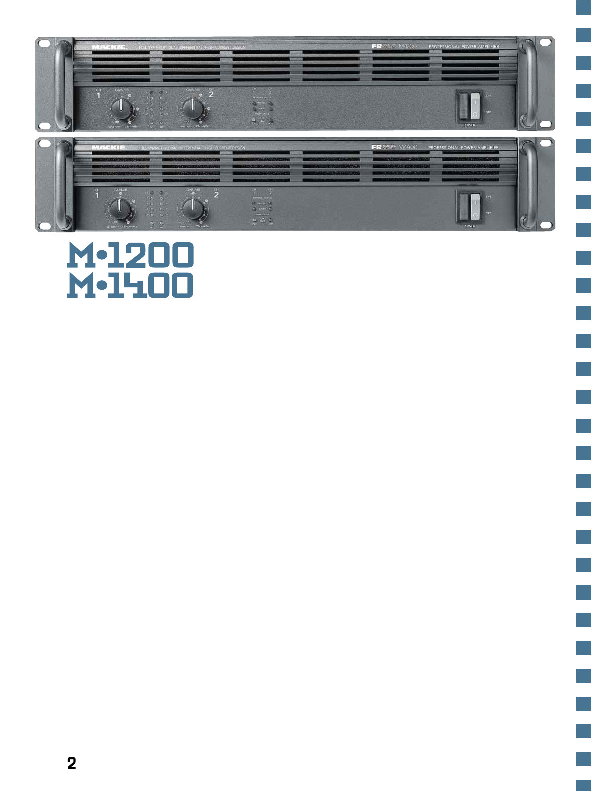
M•1200 —
1/ 4" T S output jacks
M•1400 —
Speakon® output jacks
■ 6 LED metering includ-
ing Signal Present and
Overload
■ Separate L/R Protect
LEDs indicate the
following protection
conditions:
1) Automatic turn-on
delay to prevent potentially damaging thumps
and pops from reaching
your speakers
2) Short-circuit protect
with separate L/R
indicating LEDs
3) Thermal protect with
combined Ch1 and 2 Cold
and Hot indicating LEDs
■ SCR Crowbar DC offset
protect
M•1200/M•1400
ARCHITECTS &
ENGINEERS
SPECIFICATIONS
■
“IN YOUR FACE”
SOUND REINFORCEMENT
& RECORDING BROCHURE
■ Low-cut filter with
variable frequency
control (Off – 170Hz)
■ Subsonic stabilization
eliminates ultra-lowfrequency noise caused
by microphone handling, stage rumble
■ Constant directivity horn
compensation with
variable high-frequency
boost control (2kHz to
6kHz)
■ Amp Mode switch for
Stereo, Mono, or Bridge
modes
■ Limiter to eliminate
clipping in both channels
■ Subwoofer mode switch
with dual-frequency select
(63Hz/125Hz)
■ T-Design Constant
Gradient Cooling Tunnel
uses two short tunnels
instead of one long
tunnel for improved
cooling efficiency and
output device reliability
■ Dual-speed cooling fan
■ T oroidal transformer for
reduced EMI emissions
®
1
Page 2
What is Fast Recovery?
Fast Recovery refers to the
amplifier’s ability to recover
after being over-driven into
clipping. Most amplifiers’
output circuits tend to stay
“latched” in the clipping
mode, making their recovery
time relatively slow, especially
at high frequencies. Our FR
Series amplifiers incorporate
two unique circuit designs
that completely eliminate
the latching phenomena.
The first is a Baker Clamp
diode configuration, and the
second is the use of two
additional supplies that are
at a higher voltage than the
main supplies. Without getting too technical, the result
is no latching and instant
recovery from overdrive.
Durability. A word
Mackie lives by.
Mackie mixers are wellknown for their ability to
withstand the abuses of the
road. Most of Mackie Designs’
employees have experience
as musicians, roadies, or
sound engineers in the real
world of music entertainment
and live sound reinforcement.
We know what kind of
punishment sound equipment can be subjected to,
and our engineers know
how to design equipment
that can take it.
Pro features even
amateurs can understand.
Mackie’s FR Series power
amplifiers were designed
with professionals – and
amateurs – in mind. These
amplifiers are great for live
sound reinforcement applications as well as studio or
broadcast control rooms.
With the ability to deliver
massive amounts of current
instantly, the FR Series amplifiers can handle powersucking subwoofers, yet
remain discriminating and
responsive when driving a
bank of delicate tweeters.
Power Output.
The M•1 2 00 is rated at
225 watts per channel into
8Ω, 400 watts per channel
into 4Ω and 600 watts per
channel into 2Ω. In bridge
mode the M•1200 is rated
at 800 watts into 8Ω and
12 00 watts into 4Ω.
The M•1 400 is rated at
250 watts per channel into
8Ω, 425 watts per channel
into 4Ω and 630 watts per
channel into 2Ω. In bridge
mode the M•1400 is rated
at 850 watts into 8Ω, and
12 60 watts into 4Ω.
Sustained ultra-low
impedance capability.
The FR Series power amplifiers are designed to drive
low impedance loads effortlessly and reliably. Most power
amplifiers have difficulty
driving anything lower than
4 ohms, but the FR Series
power amplifiers can easily
drive 2 ohm loads all day
long without breaking a sweat.
This is a result of the careful
and efficient design of the
heatsink and cooling tunnels,
which keep the output devices
running as cool as possible,
along with the virtual elimination of VI limiters, which
can cause lesser amplifiers
to distort or to shut down
completely when driving
low impedance loads.
Inputs, Input Level Controls
and Metering.
The FR Series amplifiers
are equipped with balanced,
line-level input connectors
for each channel in the form
of XLR female jacks and 1/ 4"
TRS phone jacks. In addition,
XLR male jacks are provided
as thru connections for daisychaining the input signal to
multiple amplifiers. The XLR
male thru jack is in parallel
with the XLR female jack
and the 1/4" TRS jack, and
any one can be used as an
input or thru connector.
2
Page 3

Each channel
has an independent gain
control with
40 detents for
accurately
setting and
matching the
gain between
channels. The
gain controls
are calibrated
in dB (from
off to 30) and
in volts (with
indications of
1V , 2V , and 3V).
Six discrete
LEDs are used
to indicate signal level for
each channel, including a
signal present LED, indicators
at –20, –9, –6, and –3dB
below full power, and an
overload LED to indicate
when the output has reached
the clipping point.
Outputs.
The M•1 2 00 and M•1400
differ in their output connector configurations. They
both come with heavy-duty
5-way binding posts, which
can accept standard double
banana plugs, spade lugs, or
bare wire (Export versions
will not accept banana plugs
due to European safety
requirements). The M•1200
also has 1/ 4" TS phone jack
outputs in parallel with the
binding posts. The M•1 400
comes with Neutrik brand
Speakon
®
connectors in par-
alle l with the binding posts.
Stereo, Mono and Bridge
modes.
The amplifiers can be operated in one of three modes.
In stereo mode, the amplifier
operates with two inputs and
two outputs. It accepts separate channel 1 and 2 input
signals, and outputs separate
channel 1 and 2 signals.
In mono mode, the ampli-
fier operates with one input
and two identical outputs. It
accepts an input signal through
channel 1, and outputs the
same signal at both channel
1 and 2 speaker outputs.
In bridge mode, the amplifier operates with one input
and one output. It accepts an
input signal through channel
1, and combines the power
of both output sections into
a single output, using the
channel 1 positive and
channel 2 positive speaker
output terminals.
Clipping eliminator.
Mackie Designs power
amplifiers use a method of
protecting the amplifier and
the speakers from clipping
that doesn’t affect the low
impedance capablility of the
amplifier. A defeatable limiter
circuit is employed that
reduces the
input signal
when the output of the
amplifier approaches the
clipping point.
Cooling tunnel airflow
The moment the output
level drops below clipping,
the limiter turns off and is
effectively “out-of-circuit,”
so it doesn’t
degrade the
audio signal in
any way.
T-Design
Constant
Gradient
Cooling
Tunnel.
Most amplifiers have a fan
in the back that
blows air (along
with dust and
other contaminants) into the
inside of the
amplifier, across
the heatsinks
as well as all the other internal components, and finally
out through the front.
These designs are cheap to
implement, but not very
efficient.
Others use a cooling tunnel with the fan at one end.
The problem with this design
is that the heat from the
first transistors warms the
air so that by the time the
air reaches the end of the
tunnel it’s too hot to provide
sufficient cooling.
Our T-Design Constant
Gradient Cooling Tunnel
offers a much more efficient
method of providing cool
air to all the transistors without blowing contaminants
all over its insides. A dualspeed fan is located in the
center of the amplifier, directing air from the front of the
amplifier
through a
large intake
manifold into
the cooling
tunnel. The
cool air is
evenly dis-
tributed
from the middle of th e tunnel to each end, where the
warm air then exits the
amplifier on either side.
3
Page 4

Block Diagram
CH 1
BALANCED
LINE INPUT
(TRS)
CH 1
BALANCED
LINE INPUT
(XLR-F)
LIMITER
LIMITER
ON
OFF
LOW CUT
FILTER
LOW PASS
FILTER
(SUBWOOFER)
+
–
80 VDC
+
–
90 VDC
TOROIDAL P OWER
TRANSFORMER
LAMP
INTERNAL
FUSE
MACKIE DESIGNS
M•1200/M•1400
BLOCK DIAGRAM
(#011497DF)
FREQ
CD EQ
FREQ
OUTPUT
APPLICATION
SWITCH
AMP
MODE
SWITCH
63 Hz
125 Hz
FREQ
TO
LIMITER
ON
OFF
LOW CUT
FILTER
FREQ
CD EQ
FREQ
CH 1
GAIN
STEREO
MONO
BRIDGE
CH 2
GAIN
INVERTING
UNITY GAIN
AMPLIFIER
ON
OFF
SUB
ON
OFF
SUB
NC
NC
NC
MUTE
CH 1
PROTECT
LED
CH 1
SHORT
LED
MUTE
CH 2
PROTECT
LED
POWER
AMPLIFIER
CH 1
SPEAKER
OUT
FUSE
–80VDC
FUSE
+80VDC
DC OFFSET
DETECT
SHORT
DETECT
METER
DRIVE
POWER
AMPLIFIER
CH 2
SPEAKER
OUT
FUSE
–80VDC
FUSE
+80VDC
DC OFFSET
DETECT
TO CH 1
MUTE
OL
–3
–6
–9
–20
SIG
CH 1
SIG
CH 2
SHORT
LED
SHORT
DETECT
METER
DRIVE
TO CH 2
MUTE
OL
–3
–6
–9
–20
SIG
CH 2
SIG
SIG
(TO CH 1
METER DRIVE)
SIG
(TO CH 2
METER DRIVE)
PD's LEASH
HOT
LED
COLD
LED
TEMP
SENSOR
(ON HEATSINK)
TO CH 1
AND CH 2
MUTE
CH 1 AMP OUT
CH 2 AMP OUT
CH 1 MUTE
CH 2 MUTE
60ºC
DETECTOR
FAN
SPEED
CONTROL
HI DCV
LO DCV
CH 1
MUTE
CH 2
MUTE
POWER
SWITCH
TO CH 1
AND CH 2
MUTE
THERMAL
PROTECT
THRU
(XLR-M)
CH 2
BALANCED
LINE INPUT
(TRS)
CH 2
BALANCED
LINE INPUT
(XLR-F)
THRU
(XLR-M)
80ºC MUTE
55ºC UNMUTE
FAN
TO HUSKY
STADIUM
1/4" TS JACK
M•1200 only
1/4" TS JACK
M•1200 only
17.25" (43.8cm)
M•1200/1400
WEIGHT
36 lbs.
(16.3 kg)
15.25" (38.7cm)
M•1200/M•1400
DIMENSIONS
16.25" (41.3cm)
1.25"
(3.2cm)
CH
GAIN/dB
3v
20
1
22
18
2v
2416
14
26
28
8
30
0
0
1v
1.23v (+4dBu)
SENSITIVITY
FULL SYMMETRY DUAL DIFFERENTIAL HIGH CURRENT DESIGN
GAIN/dB
CH
OL
3v
20
2
–3
–3
22
18
2v
2416
–6
–6
–9
14
–9
26
–20
–20
28
8
30
0
0
1v
1.23v (+4dBu)
SENSITIVITY
SIGOLSIG
CH
CH
2
1
INTERNAL STATUS
PROTECT
SHORT
TEMP STATUS
CH
1&2
COLD HOT
19.00" (48.3cm)
PROFESSIONAL POWER AMPLIFIER
POWER
2U
3.50"
ON
OFF
(8.9cm)
Built-in subwoofer crossover .
The amplifier has a subwoofer mode that allows you
to turn on the built-in subwoofer crossover. W hen
activated, the signals appearing at the left and right inputs
are summed, directed to a
low-pass filter, and routed
to both output stages. A
switch selects the cutoff frequency of the filter at either
63Hz or 12 5Hz, and the amplifier can be set to either mono
or bridge mode of operation.
Built-in constant directivity
horn compensation.
When a compression driver
is attached to a constant
directivity (CD) horn, it requires
a certain amount of high-
4
Page 5

frequency boost to compensate for the natural roll-off
inherent in all compression
drivers. Some speaker manufacturers provide external
processors with plug-in
modules for each of the
various combinations of
horns and drivers (at an
additional cost to you!) to
compensate the CD horns.
Each channel of an FR
Series power amplifier has
its own built-in CD horn
compensation circuit. All you
need to do is set the variablefrequency horn EQ control on
the amplifier to the manufacturer’s recommended mass
breakpoint frequency (the
point where the frequency
response begins to roll o f f ).
As an added feature, if you’re
not using CD horns, set the
frequency control fully clockwise to the AIR setting to enjo y Mackie’s exclusive AIR
EQ, a gentle high-frequency
boost that brightens and
lightens the sound.
Low-cut filter.
Virtually all loudspeakers
have a low-frequency cutoff
point somewhere above
20Hz. Many low-frequency
drivers have a –3dB point
at 35Hz to 40Hz, while many
stage monitor speakers cut
off at about 100Hz; there’s
no sense in amplifying low-
frequency signals that the
loudspeaker cannot reproduce.
Each channel of the FR
Series amplifiers has a continuously variable low-cut
filter. Simply dial in the frequency at which the loudspeakers drop off (anywhere
from OFF to 170Hz), and
reap the benefits of saving
amplifier power with
cleaner, tighter bass.
Built-in subsonic stabilizer.
Even with the low-cut
filter set to the OFF position,
each channel of the FR Series
amplifiers has a built-in
subsonic stabilizer (technically
called infrasonic stabilizer).
This dampens the very low
frequencies, which can be
caused by microphone
handling or stage rumble.
These frequencies are below
the threshold of human
hearing, and rob the amplifier
of power and contribute to
intermodulation distortion.
Protection circuits.
Both amplifiers are
equipped with a number of
unique and innovative protection circuits to ensure the
safety of your speakers and
the amplifiers.
Separate left and right
Protect LEDs on the front
panel indicate when a protection circuit has been activated.
For example, when the amplifier is first turned on the
outputs are muted for three
seconds, during which time
the Protect LEDs are lit. This
allows time for all the equipment in the system to power
up and stabilize, and prevents
potentially damaging thumps
or pops from propagating
to the speakers.
Separate left and right
Short LEDs indicate if there
is a short circuit at the
speaker output terminals.
This lets you know at a glance
to check the speaker wiring
for shorts (or recalculate the
speaker load impedance)
right from the get-go, so you
don’t waste precious time
searching for the problem.
Combined left and right
Cold and Hot LEDs indicate
if the amplifier has overheated.
Under normal operation,
the Cold LED remains lit. If
the Hot LED should light,
the outputs become muted
until the amplifier cools to
a safe operating temperature,
then normal operation ensues.
The FR Series: The most
affordable, full-featured
power amplifiers available.
As you can see, there is
every reason the M•1200
and M•1400 are fast becoming
the premier affordable choice
for many sound reinforcement
and recording applications.
With their proven durability ,
professional features and
specs, and certainly not least,
low cost – the FR Series is
destined to be a classic.
There are no other power
amplifiers in their class with
all these features at such
an affordable price.
And that’s why people
from all professions, with
all kinds of different applications, prefer Mackie’s FR Series.
Y ou’ll like them because of
their low price, easy-to-use
features, and rugged construction. That’s got to sound good.
And, of course, Mackie does.
5
Page 6

SPECIFICATIONS
Continuous Average Output
Power, both channels driven:
M•1200
225 watts per channel into
8 ohms from 20Hz to 20kHz, with
no more than 0.025% THD
400 watts per channel into
4 ohms from 20Hz to 20kHz, with
no more than 0.050% THD
600 watts per channel into
2 ohms from 20Hz to 20kHz, with
no more than 0.095% THD
Bridged mono operation:
800 watts into 8 ohms from 20Hz
to 20kHz, with no more than
0.05% THD
1200 watts into 4 ohms from
20Hz to 20kHz, with no more
than 0.095% THD
Maximum Power at 1% THD (per
IHF-A-202):
250 watts per channel into 8Ω
425 watts per channel into 4Ω
640 watts per channel into 2Ω
850 watts into 8Ω bridged
1280 watts into 4Ω bridged
M•1400
250 watts per channel into
8 ohms from 20Hz to 20kHz, with
no more than 0.01 2% THD
425 watts per channel into
4 ohms from 20Hz to 20kHz, with
no more than 0.025% THD
630 watts per channel into
2 ohms from 20Hz to 20kHz, with
no more than 0.050% THD
Bridged mono operation:
850 watts into 8 ohms from 20Hz
to 20kHz, with no more than
0.025% THD
1260 watts into 4 ohms from
20Hz to 20kHz, with no more
than 0.050% THD
Maximum Power at 1% THD (per
IHF-A-202):
280 watts per channel into 8Ω
480 watts per channel into 4Ω
700 watts per channel into 2Ω
960 watts into 8Ω bridged
1400 watts into 4Ω bridged
Note: Power ratings are specified
at 120VAC (U.S. and Canada) and
240VA C (Export) line voltages.
Power Bandwidth:
20Hz to 70kHz (+0, –3dB)
Frequency Response:
20Hz to 40kHz (+0, –1dB)
10Hz to 7 0kHz (+0, –3dB)
Distortion:
THD, SMPTE IMD, TIM
< 0.025%@8Ω
< 0.050%@4Ω
< 0.150%@2Ω
Signal to Noise Ratio:
> 10 7dB below rated
power into 4 ohms
Channel Separation:
> 80dB@1kHz
Damping Factor:
> 350 from 0 to 400Hz
Input Impedance:
20kΩ balanced bridging
Input Sensitivity:
1.23 volts (+4dBu) for rated
power into 4 ohms
Gain:
30.25dB (32.5V/V)
Maximum Input Level:
9.75 volts (+22dBu)
Rise Time: < 4.4µs
Slew Rate:
Voltage Slew Rate > 50V/µs
> 100V/µs bridged
Current Slew Rate
> 32A/µs at 2Ω
CMRR: > 40dB, 20Hz to 20kHz
T ransient Recovery:
< 1µs for 20dB overdrive @ 1kHz
High Frequency Overload and
Latching:
No latch up at any frequency or
level
Variable Low-Cut Filter:
10Hz (Off) to 170Hz,
2nd Order Bessel
Subwoofer Low-Pass Filter:
Switched: 63Hz/125Hz,
3rd Order Bessel
Constant Directivity High
Frequency Boost:
2kHz to 6kHz (+3dB points)
6dB/octave high-frequency
shelving filter, (shelving occurs at
approximately 30kHz)
T urn On Delay:
3 seconds
Limiter Section:
Complementary Positive and
Negative Peak Detecting
Indicators:
Six meter LEDs per channel
SIG (Signal Present),
–20, –9, –6, –3, OL (Overload)
CH 1 & 2
PROTECT LEDs
SHORT LEDs
TEMP STATUS
COLD, HO T LEDs
Power Consumption:
M•1200 120V 240V
65 watts at idle 0.9A 0.5A
500 watts with musical program
fully loaded 6.4A 3.2A
(4Ω per side, or 8Ω bridged)
850 watts with musical program
fully loaded 10.0A 5.0A
(2Ω per side, or 4Ω bridged)
800 watts at full power into 8Ω
(cont. sine wave) 9.3A 4.7A
1400 watts at full power into 4Ω
(cont. sine wave) 15.0A 7.5A
2400 watts at full power into 2Ω
(cont. sine wave) 24.3A 12.2A
M•1400 120V 240V
65 watts at idle 0.9A 0.5A
550 watts with musical program
fully loaded 6.7A 3.4A
(4Ω per side, or 8Ω bridged)
900 watts with musical program
fully loaded 10.5A 5.3A
(2Ω per side, or 4Ω bridged)
850 watts at full power into 8Ω
(cont. sine wave) 9.6A 4.8A
1500 watts at full power into 4Ω
(cont. sine wave) 15.6A 7.8A
2500 watts at full power into 2Ω
(cont. sine wave) 24.8A 12.4A
AC Line Power:
US 120VAC, 60Hz
Europe 240VA C, 50/60Hz
Japan 100V AC, 50/60Hz
Korea 220VAC, 60Hz
AC Drop-out V oltage:
At approximately 50% of rated
line voltage
Physical:
Height: 2U = 3.5" (89mm)
Width: 19.0" (483mm)
Depth: 15.25" (3 87mm)
Handle Depth: 1.25" (32mm)
Overall Depth: 16.2 5" (413mm)
Weight: 36 lbs (16.3kg)
®
MACKIE DESIGNS INC.
16220 Wood-Red Rd. NE , Woodinville • WA • 98072 • USA
Toll-Free 800/258-6883 • FAX 425/487-4337 •
E-mail: sales@mackie.com • www.mackie.com
6
For distribution information outside the USA,
425/487-4333 • FAX 425/485-1152
Mackie Designs Inc. is engaged in a continuous
pr o gr a m o f p r o d u c t e va l u a t i o n and improvement
and reserves the right to change product
specifications at any time without notice.
®
The following are trademarks or registered
trademarks of Mackie Designs Inc.: “Mackie.”,
the Running Man, and FR Series.
Speakon is a registered trademark of Neutrik.
Part No. 091-096-00 Rev. B 2/98
1997-1998 Mackie Designs Inc. All Rights
©
Reserved.
 Loading...