

Mackie M1200/M1400, FR Series M.1400, FR Series M-1200 Owner's Manual
OL
–3
–6
–9
–20
–3
–6
–9
–20
SIG
OL
SIG
CH
1
30
28
26
20
22
18
2416
14
8
0
0
1.23v (+4dBu)
SENSITIVITY
GAIN/dB
CH
2
PROTECT
COLD HOT
SHORT
TEMP STATUS
INTERNAL STATUS
CH
1
CH
2
CH
1&2
ON
OFF
POWER
3v
2v
1v
30
28
26
20
22
18
2416
14
8
0
0
1.23v (+4dBu)
SENSITIVITY
GAIN/dB
3v
2v
1v
PROFESSIONAL POWER AMPLIFIER
FULL SYMMETRY DUAL DIFFER ENTIAL HIGH CURRENT DESIGN
CHANNEL
2
1
CHANNEL
CH
1
CH
2
SPEAKER OUTPUTS
+
––
+
63Hz
125Hz
CONSTANT DIRECTIVITY
HORN EQ/AIR EQ
CONSTANT DIRECTIVITY
HORN EQ/AIR EQ
INPUT
THRUTHRU
INPUT
AMP MODE
FREQUENCY
4.5 k Hz
ON
5.6k Hz
2k Hz
MONO
BRIDGE
LIMITER
(CH1 & CH2)
OFF
FULL
RANGE
SUB
WOOFER
LOW CUT
FILTER
LOW CUT
FILTER
OUTPUT APPLICATION
SERIAL NUMBER
MANUFACTURING DATE
RISK OF ELECTRIC SHOCK
DO NOT OPEN
REPLACE WITH THE SAME TYPE FUSE AND RATING.
DISCONNECT SUPPLY CORD BEFORE CHANGING FUSE
UTILISE UN FUSIBLE DE RECHANGE DE MÊME TYPE.
DEBRANCHER AVANT DE REMPLACER LE FUSIBLE
WARNING:
TO REDUCE THE RISK OF FIRE OR ELECTRIC SHOCK, DO NOT
EXPOSE THIS EQUIPMENT TO RAIN OR MOISTURE. DO NOT REMOVE COVER.
NO USER SERVICEABLE PARTS INSIDE. REFER SERVICING TO QUALIFIED PERSONNEL.
CAUTION
AVIS:
RISCQUE DE CHOC
É
LECTRIQUE — NE PAS OUVRIR
BALANCED
OR
UNBALANCED
BALANCED
OR
UNBALANCED
AIR EQ
MONO
BRIDGE
ON
/ BRIDGE/ MONO
170 Hz
OFF
CONCEIVED, DESIGNED, AND MANUFACTURED
BY MACKIE DESIGNS INC • WOODINVILLE • WA
98072 • USA • MADE IN USA • PATENTS PENDING
4.5k Hz
5.6k Hz
2k Hz
AIR EQ
120 VAC 50/60 Hz
1500 WATTS
+
–
170 Hz
100 Hz
OFF
STAGE
MONITOR
100 Hz
STAGE
MONITOR
OFF
TYPICAL
ON
OFF
TYPICAL
TYPICAL
35 Hz
TYPICAL
35 Hz
(MONO BRIDGE)
1200 WATTS
4 OHM LOAD MIN.
600 WATTS CH
2 OHMS LOAD MIN.
STEREO
TYPICAL
STEREO
TYPICAL
AIR EQ
AIR EQ
™
M•1200/M•1400
OWNER’S MANUAL
™
HIGH-CURRENT POWER AMPLIFIERS
CAUTION AVIS
RISK OF ELECTRIC
RISQUE DE
CAUTION: TO REDUCE THE RISK OF ELECTRIC SHOCK
NO USER-SERVICEABLE PARTS INSIDE
REFER SERVICING TO QUALIFIED PERSONNEL
ATTENTION: POUR EVITER LES RISQUES DE CHOC
ELECTRIQUE, NE PAS ENLEVER LE COUVERCLE. AUCUN
ENTRETIEN DE PIECES INTERIEURES PAR L'USAGER. CONFIER
L'ENTRETIEN AU PERSONNEL QUALIFIE.
AVIS: POUR EVITER LES RISQUES D'INCENDIE OU
D'ELECTROCUTION, N'EXPOSEZ PAS CET ARTICLE
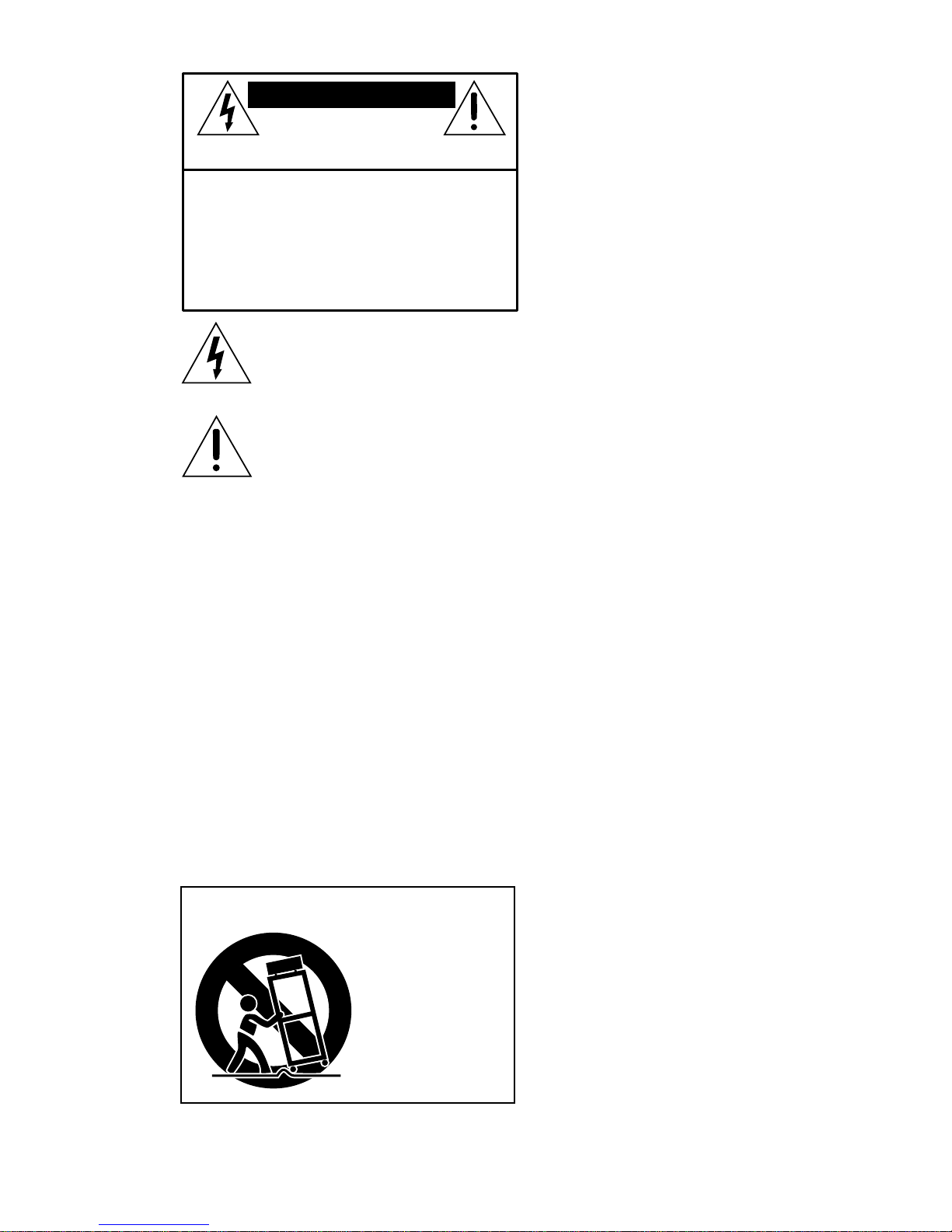
The lightning flash with arrowhead symbol within an equilateral
triangle is intended to alert the user to the presence of uninsulated
"dangerous voltage" within the product's enclosure, that may be
of sufficient magnitude to constitute a risk of electric shock to persons.
Le symbole éclair avec point de flèche à l'intérieur d'un triangle
équilatéral est utilisé pour alerter l'utilisateur de la présence à
l'intérieur du coffret de "voltage dangereux" non isolé d'ampleur
suffisante pour constituer un risque d'éléctrocution.
The exclamation point within an equilateral triangle is intended to
alert the user of the presence of important operating and maintenance
(servicing) instructions in the literature accompanying the appliance.
Le point d'exclamation à l'intérieur d'un triangle équilatéral est
employé pour alerter les utilisateurs de la présence d'instructions
importantes pour le fonctionnement et l'entretien (service) dans le
livret d'instruction accompagnant l'appareil.
DO NOT OPEN
CHOC
NE PAS OUVRIR
DO NOT REMOVE COVER (OR BACK)
A LA PLUIE OU A L'HUMIDITE
SHOCK
ELECTRIQUE
SAFETY INSTRUCTIONS
1. Read Instructions — All the safety and operation
instructions should be read before this Mackie product is
operated.
2. Retain Instructions — The safety and operating
instructions should be kept for future reference.
3. Heed Warnings — All warnings on this Mackie product and
in these operating instructions should be followed.
4. Follow Instructions — All operating and other instructions
should be followed.
5. Water and Moisture — This Mackie product should not be
used near water – for example, near a bathtub, washbowl,
kitchen sink, laundry tub, in a wet basement, near a
swimming pool, swamp or salivating St. Bernard dog, etc.
6. Heat — This Mackie product should be situated away
from heat sources such as radiators, or other devices which
produce heat.
PORTABLE CART WARNING
Carts and stands - The
Component should be used
only with a cart or stand
that is recommended by
the manufacturer.
A Component and cart
combination should be
moved with care. Quick
stops, excessive force, and
uneven surfaces may cause
the Component and cart
combination to overturn.
7. Power Sources — This Mackie product should be
connected to a power supply only of the type described in
these operation instructions or as marked on this Mackie
product.
8. Power Cord Protection — Power supply cords should be
routed so that they are not likely to be walked upon or
pinched by items placed upon or against them, paying
particular attention to cords at plugs, convenience receptacles,
and the point where they exit this Mackie product.
9. Object and Liquid Entry — Care should be taken so that
objects do not fall into and liquids are not spilled into this
Mackie product.
10. Damage Requiring Service — This Mackie product
should be serviced only by qualified service personnel when:
A. The power-supply cord or the plug has been
damaged; or
B. Objects have fallen, or liquid has spilled into
this Mackie product; or
C. This Mackie product has been exposed to rain;
or
D. This Mackie product does not appear to operate
normally or exhibits a marked change in
performance; or
E. This Mackie product has been dropped, or its
chassis damaged.
11. Servicing — The user should not attempt to service this
Mackie product beyond those means described in this
operating manual. All other servicing should be referred to the
Mackie Service Department.
12. To prevent electric shock, do not use this polarized plug
with an extension cord, receptacle or other outlet unless the
blades can be fully inserted to prevent blade exposure.
Pour préevenir les chocs électriques ne pas utiliser cette fiche
polariseé avec un prolongateur, un prise de courant ou une
autre sortie de courant, sauf si les lames peuvent être insérées
à fond sans laisser aucune pariie à découvert.
13. Grounding or Polarization — Precautions should be
taken so that the grounding or polarization means of this
Mackie product is not defeated.
14. This apparatus does not exceed the Class A/Class B
(whichever is applicable) limits for radio noise emissions from
digital apparatus as set out in the radio interference
regulations of the Canadian Department of Communications.
ATTENTION —Le présent appareil numérique n’émet pas de
bruits radioélectriques dépassant las limites applicables aux
appareils numériques de class A/de class B (selon le cas)
prescrites dans le règlement sur le brouillage radioélectrique
édicté par les ministere des communications du Canada.
WARNING — To reduce the risk of fire or electric shock, do
not expose this appliance to rain or moisture.
Lend Me Your Ears
Exposure to extremely high
noise levels may cause permanent hearing loss.
Individuals vary considerably
in susceptibility to noise-induced hearing loss, but
nearly everyone will lose some hearing if exposed
to sufficiently
intense
noise for a
period of
time. The
U.S.
Government’s
Occupational
Safety and
Health Administration (OSHA) has specified the permissible
noise level exposures shown in this chart.
Duration Per Day Sound Level dBA, Typical
In Hours Slow Response Example
8 90 Duo in small club
692
4 95 Subway Train
397
2 100 Very loud classical music
1.5 102
1 105 Lori screaming at Ron about deadlines
0.5 110
0.25 or less 115 Loudest parts at a rock concert
INTRODUCTION
According to OSHA, any exposure in excess of
these permissible limits could result in some hearing loss. To ensure against potentially dangerous
exposure to high sound pressure levels, it is recommended that all persons exposed to equipment
capable of producing high sound pressure levels
(such as this amplification system) use hearing
protectors
while this
unit is in
operation.
Ear plugs
or protectors in the
ear canals
or over the
ears must
be worn
when operating this amplification system in order to prevent
a permanent hearing loss if exposure is in excess of
the limits set forth here.
Thank you for choosing a Mackie Designs
power amplifier! W e appr eciate your vote of
confidence for the folks in W oodinville who
specialize in awesome and affordable audio.
The Mackie Designs M•1200/M•1400 Power
Amplifiers are designed to fulfill the amplification needs of almost any type of application.
They boast a wealth of features you’d expect to
pay extra for — like subwoofer filtering, constant directivity equalization, speaker-protecting
limiter , and gobs of ultra-clean power, to name
a few.
Perhaps the most important feature of the
FR Series™ Power Amplifiers is the attention
amplifier that performs better than conventional designs when presented with adverse
conditions. One of the most difficult things for
a power amplifier to handle is clipping. Conventional designs use lots of negative feedback
to provide stability and lower distortion. When
clipping occurs, this “feedback” causes highfrequency sticking, keeping the amplifier
“latched” in the clipping state longer than necessary. This r esults in painfully audible
distortion. Our Fast Recovery design eliminates
this high-frequency sticking and allows the amplifier to remain stable when powering highly
reactive loads at high volume levels.
to detail in every aspect of the design. At Mackie,
we know what it takes to be roadworthy. After
all, our mixers have traveled all over the world
under the worst of conditions, and we’ve applied
what we’ve learned to the mechanical design of
our amplifiers.
Roadworthiness is only part of the picture.
needs an owner’s manual. After all, you just
plug in a few cables and power it up. W ell, it’ s
almost that simple. There’s just a few things
that we’d like you to be aware of, and we’ll dis-
cuss those right away — please see the Quick
Start
W e know that r eliability is paramount to sound
reinforcement. That’s why we use double-sided
thru-hole-plated fiberglass printed circuit
boards. That’s why our engineers have sub-
The M•1200/M•1400 amplifiers have a wealth
of useful features, and each of them is explained
in detail.
jected the amplifier to the most rigorous and
punishing tests imaginable, to fine-tune the
design and extend its limits beyond those of
ordinary amplifiers.
Fast Recovery — where the “FR” comes
Please write your serial number here for
future reference (i.e., insurance claims,
tech support, return authorization, etc.):
from — is more than a buzzword. It is based on
real, proven design principles. The result is an
Part No. 820-062-00 Rev. A 12/96
©1996 Mackie Designs, All Rights Reserved. Printed in the U.S.A.
Y ou may wonder why a power amp even
on the next page.
Then go ahead and read the entire manual.
TM
3

READ THIS PAGE!
QUICK ST ART
I got ants in my pants and I got to dance!
INSTALLATION
The M•1200/M•1400
amps can be mounted in
any standard rack system
(see
tally on a floor or table. The heavier internal
components are located towards the front of
the chassis to make it easier to hold the amp
by its front handles.
They need plenty of fresh air to stay cool.
DO NOT BLOCK THE VENTILATION PORTS
(see
).
CONNECTIONS AND SETTINGS
1. Be sure the
making connections.
2. Turn the
(counterclockwise) for now.
3. Set both
their
4. Set both
switches
directivity horns with compression drivers).
5. Set the
Note: If you’re using the M•1200/M•1400 to
power a subwoofer , you probably do not need
an external crossover . Please see
POWER
GAIN
controls fully down
LOW CUT FILTER
TYPICAL
marks (35Hz).
CONSTANT DIRECTIVITY
OFF
(unless you’re using constant
LIMITER
), or placed horizon-
IMPORTANT: The
M•1200/M•1400 amps
draw their ventilation air
in from the front and out
through the side panels.
switch is off befor e
controls to
switch on.
for details.
6. Determine which
AMP MODE
is best
for your application:
STEREO
•
mode (separate left and right
inputs, separate left and right outputs) is
the typical setup for amplifying stereo
signals.
MONO
•
mode (sometimes called DualMono mode – one mono input, two mono
outputs) is for sending a mono signal to
two different speaker sets, with separatelyadjustable level controls.
BRIDGE
•
mode (sometimes called
Bridged-Mono – one mono input, one mono
output) uses both sides of the amp to
double the power to one speaker set. An
M•1200 power amplifier , set to
BRIDGE
mode, delivers 1200 watts (into 4 ohms).
The M•1400 delivers 1260 watts. Garsh!
Note: 4 ohms is the minimum impedance
you should connect to the amplifier in
BRIDGE
mode. If you connect a lower impedance load
BRIDGE
in
light, putting the amplifier into
mode, the
SHORT
LEDs may
PROTECT
mode.
Set the
7. In
AMP MODE
STEREO
mode, connect line-level cables
switch accordingly .
from your signal source to the M•1200/
INPUT
M•1400’s
jacks, either XLR or
TRS:
• The XLR and TRS inputs for each
channel are wired in parallel.
• The balanced XLR inputs are wired
pin 2 = hot (+), pin 3 = cold (–) and
pin 1 = shield (ground).
FULL SYMMETRY DUAL DIFFERENTIAL HIGH CURRENT DESIGN
GAIN/dB
CH
1
14
SENSITIVITY
OL
3v
20
–3
22
18
8
30
0
0
1v
1.23v (+4dBu)
–3
2v
2416
–6
–6
–9
14
–9
26
–20
–20
28
SIGOLSIG
8
SENSITIVITY
4
GAIN/dB
18
0
0
3v
20
1.23v (+4dBu)
PROFESSIONAL POWER AMPLIFIER
CH
CH
2
22
2v
2416
26
28
30
1v
CH
1
INTERNAL STATUS
PROTECT
SHORT
TEMP STATUS
CH
1&2
COLD HOT
2
ON
OFF
POWER
• The 1/4" TRS inputs are wired
tip = hot (+), ring = cold (–) and
sleeve = shield (ground), and can accept
either balanced (TRS) or unbalanced (TS)
cables.
MONO
8. In
input cable to
and nothing into
(Y ou could plug into
and
BRIDGE
CHANNEL 1
CHANNEL 2
modes, connect an
’s
INPUT
’s
INPUT
CHANNEL 2
’s input,
only,
it just won’t do anything.)
STEREO
9. In
speaker cables to the
and
MONO
modes, connect
SPEAKER OUTPUTS
, either binding post or 1/4" TS for the
M•1200, or binding post or Speakon
®
the M•1400:
• The binding post connectors are wired
red = hot (+) and black = cold (–).
• The 1/4" TS connectors are wired
tip = hot (+) and sleeve = cold (–).
10.In
BRIDGE
mode, connect the binding post
cable like this: the hot (+) side goes in the
CHANNEL 1 SPEAKER OUTPUTS
post and the cold (–) side goes in
s red post. Plug nothing into the
NEL 2’
red
CHAN-
black posts, 1/4" TS jacks, or Speakon jacks.
11.Connect the other ends of the speaker
cables to your loudspeakers.
12.Plug the amp’s power cord
into a
3-prong AC outlet capable of delivering at
least 15 amps.
13.Make sure your signal source (the cables
feeding the M•1200/M•1400’s inputs)
is powered up and delivering signal to
the amp.
14.Turn the M•1200/M•1400’s
POWER
switch on and verify that the signal present
(
SIG
) LEDs are blinking.
.
for
GAIN
15.Slowly turn both
controls up:
Y ou should hear the music and see the
and meter LEDs flashing. If the
OL
topmost LEDs (named
are flashing, turn down either the
, for OverLoad)
GAIN
controls on the amp or the source signal’s
output level controls (i.e., master faders).
OL
The point is: The
LEDs should never
light up.
16.For quieter listening, it is preferable to
GAIN
adjust the amp’s
controls rather
than the source signal’s output level
(unless you have the source’s control all
the way up!).
17.Start dancing, but don’t let the ants out of
your pants.
Things You Must Remember:
• Never plug amplifier
outputs into anything
except speakers (unless
you have an outboard box
specifically designed to
handle speaker-level
signals).
• Before making connections to an amp or
reconfiguring an amp’s routing, turn the
GAIN
amp’s level (
) controls down, turn
the power off, make the changes, turn
the power back on, and then turn the
level controls back up.
• If you shut down your equipment, turn
off the amplifiers first. When powering
up, turn on the amplifiers last.
• Save the shipping boxes! You may need
them someday, and you probably don’t
want to have to pay for them again.
SIG
(MONO BRIDGE)
1200 WATTS
4 OHM LOAD MIN.
600 WATTS CH
2 OHMS LOAD MIN.
120 VAC 50/60 Hz
1500 WATTS
CAUTION
RISK OF ELECTRIC SHOCK
REPLACE WITH THE SAME TYPE FUSE AND RATING.
DISCONNECT SUPPLY CORD BEFORE CHANGING FUSE
CH
1
DO NOT OPEN
+
SPEAKER OUTPUTS
MONO
BRIDGE
+
WARNING:
EXPOSE THIS EQUIPMENT TO RAIN OR MOISTURE. DO NOT REMOVE COVER.
NO USER SERVICEABLE PARTS INSIDE. REFER SERVICING TO QUALIFIED PERSONNEL.
AVIS:
–
TO REDUCE THE RISK OF FIRE OR ELECTRIC SHOCK, DO NOT
RISCQUE DE CHOC ÉLECTRIQUE — NE PAS OUVRIR
UTILISE UN FUSIBLE DE RECHANGE DE MÊME TYPE.
DEBRANCHER AVANT DE REMPLACER LE FUSIBLE
CH
2
+
––
MANUFACTURING DATE
SERIAL NUMBER
CONCEIVED, DESIGNED, AND MANUFACTURED
BY MACKIE DESIGNS INC • WOODINVILLE • WA
98072 • USA • MADE IN USA • PATENTS PENDING
1
CHANNEL
OFF
2k Hz
LOW CUT
/ BRIDGE/ MONO
FILTER
TYPICAL
35 Hz
STAGE
MONITOR
100 Hz
170 Hz
CONSTANT DIRECTIVITY
HORN EQ/AIR EQ
4.5 k Hz
5.6k Hz
AIR EQ
AIR EQ
BALANCED
OR
UNBALANCED
ON
OFF
TYPICAL
INPUT
AMP MODE
MONO
STEREO
TYPICAL
OUTPUT APPLICATION
FULL
RANGE
LIMITER
(CH1 & CH2)
STEREO
TYPICAL
OFF
ON
WOOFER
CHANNEL
2
BALANCED
OR
UNBALANCED
ON
OFF
TYPICAL
OFF
CONSTANT DIRECTIVITY
HORN EQ/AIR EQ
2k Hz
LOW CUT
FILTER
TYPICAL
35 Hz
4.5k Hz
STAGE
MONITOR
100 Hz
170 Hz
5.6k Hz
AIR EQ
AIR EQ
BRIDGE
SUB
FREQUENCY
125Hz
63Hz
INPUT
THRUTHRU
5
HOW TO USE THIS MANUAL
APPLICATION DIAGRAMS
Mackie’s gang of illustrators have created
easy-to-understand diagrams of popular studio
and live-sound setups. Y our setup will probably
be different in some way , but these diagrams
will help you see the big picture so you can add
your own finishing touches.
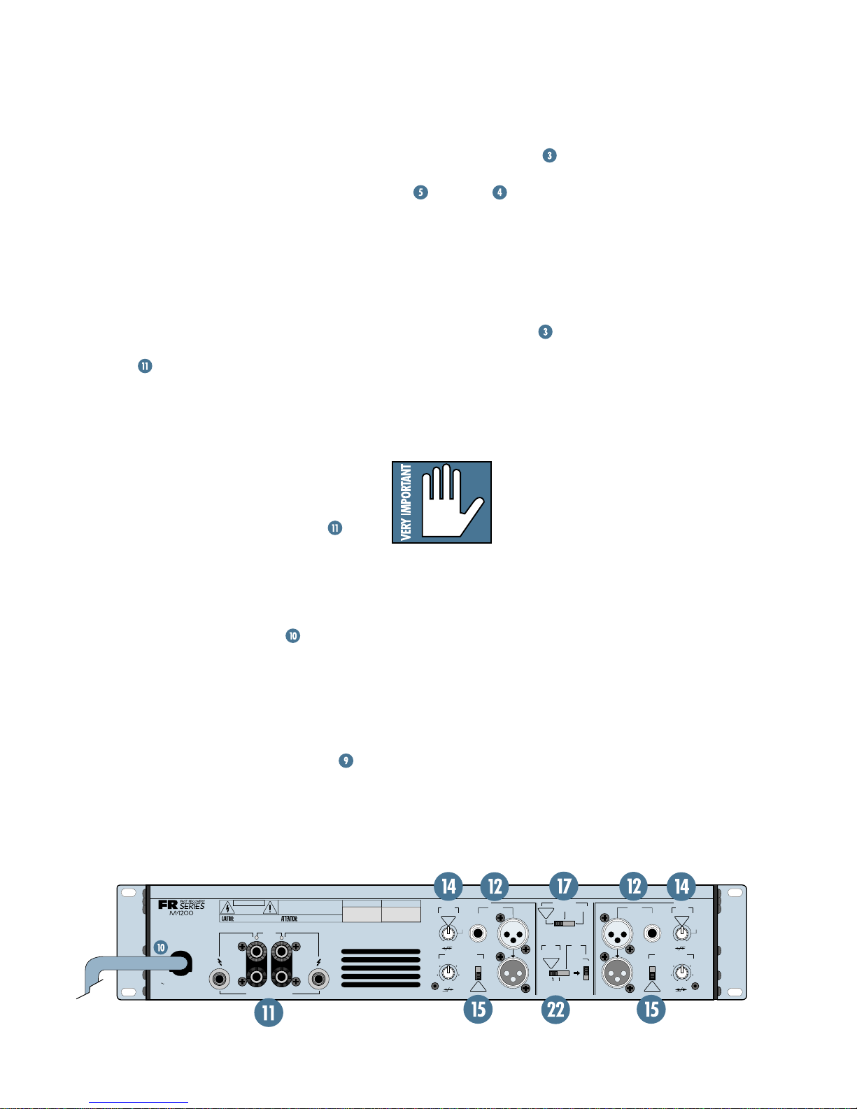
FEATURE DESCRIPTIONS: MIND
BOGGLING DET AILS
Each and every knob, switch, and connector
on the M•1200/M•1400 Power Amplifiers is
explained in depth here. Throughout this section you’ll find illustrations, with each feature
numbered like this
a feature, simply locate it on the appropriate
illustration, note the number attached to it,
and find that number in the nearby paragraphs.
This icon marks information that is critically important or unique to the M•1200/
M•1400. For your own good, read them and remember them. W e may call you someday and
quiz you.
. If you’re curious about
THE GLOSSARY: A HAVEN OF NONTECHINESS FOR THE NEOPHYTE
Just in case you’re new to the audio world,
we’ve included a fairly comprehensive dictionary of pro audio terms. If terms like “clipping,”
“noise floor ,” or “unbalanced” leave you blank,
flip to the glossary at the back of this manual
for a quick explanation.
A PLUG FOR THE CONNECTORS
SECTION
Also at the back of this manual is a section
on connectors: XLR, TRS, Binding Post and
Speakon connectors, balanced connectors,
unbalanced connectors, and special hybrid
connectors. If you plan on wiring your own
cables, please visit this section before you start.
ARCANE MYSTERIES ILLUMINA TED
Almost last but not least, we’ve included
an appendix entitled Arcane Mysteries Illumi-
nated. This section discusses some of the down
’n’ dirty practical realities of signal transmission,
balancing a sound system, grounding, and balanced versus unbalanced lines. It’s a gold mine
for the neophyte and even the seasoned pro
might learn a thing or two.
TECHNICAL INFO
This section is for you tech-heads who like
to use a calculator and read specifications.
Y ou’ll find it all her e.
This icon leads you to in-depth explanations
of features and practical tips. While not mandatory, they’ll have some valuable information.
GENERAL PRECAUTIONS AND
CONSIDERA TIONS
This section discusses important things to
keep in mind when installing and using the
M•1200/M•1400, including rack mounting, AC
power , and wiring.
6
CONTENTS
QUICK STAR T.......................................................... 4
APPLICATION DIAGRAMS.........................................8
FEATURE DESCRIPTIONS .............................................. 11
GAIN............................................................. 11
METERS ......................................................... 12
SIG ............................................................... 13
PROTECT........................................................ 13
SHORT........................................................... 13
TEMP ST ATUS ................................................. 14
POWER ......................................................... 14
POWER CORD ................................................ 15
SPEAKER OUTPUTS ......................................... 15
INPUT ........................................................... 16
THRU ............................................................ 18
LOW CUT FILTER ............................................. 18
CONSTANT DIRECTIVITY .................................. 18
CD FREQUENCY ........................................ 19
AMP MODE.................................................... 19
STEREO ...................................................20
MONO .................................................... 20
BRIDGE ................................................... 20
OUTPUT APPLICATION..................................... 20
LIMITER................................................... 20
SUBWOOFER............................................ 21
FREQUENCY ............................................. 21
GENERAL PRECAUTIONS AND CONSIDERATIONS............. 23
RACK MOUNTING ........................................... 23
THERMAL CONSIDERATIONS ............................ 23
AC POWER CONSIDERATIONS........................... 23
INPUT WIRING ............................................... 24
OUTPUT WIRING ............................................ 24
70V DISTRIBUTION SYSTEMS ........................... 25
APPENDIX A: Service Info ............................................ 26
TROUBLESHOOTING ............................................. 26
REPAIR ............................................................... 27
APPENDIX B: Glossary................................................. 28
APPENDIX C: Connectors.............................................. 33
APPENDIX D: Arcane Mysteries Illuminated .................... 35
Balanced Lines ...................................................... 35
“Do’s” and “Don’ts” of Fixed Installations............... 35
Grounding............................................................ 36
Optimizing Sound System Levels ............................. 36
Biamplified and T riamplified Systems ....................... 38
APPENDIX E: T echnical Info........................................... 39
DO THE MATH: OHMS, LOADS AND SUCH................ 39
SPECIFICATIONS................................................... 40
BLOCK DIAGRAM ................................................. 42
COLOPHON................................................................ 43
7
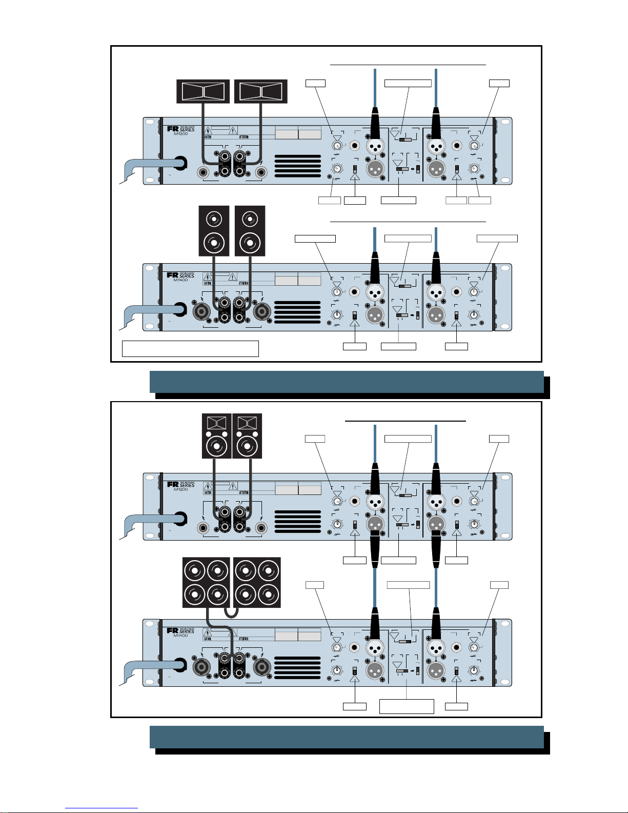
APPLICATION DIAGRAMS
CHANNEL
2
1
CHANNEL
CH
1
CH
2
SPEAKER OUTPUTS
+
––
+
63Hz
125Hz
CONSTANT DIRECTIVITY
HORN EQ/AIR EQ
CONSTANT DIRECTIVITY
HORN EQ/AIR EQ
INPUT
THRUTHRU
INPUT
AMP MODE
FREQUENCY
4.5 k Hz
ON
5.6k Hz
2k Hz
MONO
BRIDGE
LIMITER
(CH1 & CH2)
OFF
FULL
RANGE
SUB
WOOFER
LOW CUT
FILTER
LOW CUT
FILTER
OUTPUT APPLICATION
SERIAL NUMBER
MANUFACTURING DATE
RISK OF ELECTRIC SHOCK
DO NOT OPEN
REPLACE WITH THE SAME TYPE FUSE AND RATING.
DISCONNECT SUPPLY CORD BEFORE CHANGING FUSE
UTILISE UN FUSIBLE DE RECHANGE DE MÊME TYPE.
DEBRANCHER AVANT DE REMPLACER LE FUSIBLE
WARNING:
TO REDUCE THE RISK OF FIRE OR ELECTRIC SHOCK, DO NOT
EXPOSE THIS EQUIPMENT TO RAIN OR MOISTURE. DO NOT REMOVE COVER.
NO USER SERVICEABLE PARTS INSIDE. REFER SERVICING TO QUALIFIED PERSONNEL.
CAUTION
AVIS:
RISCQUE DE CHOC
É
LECTRIQUE — NE PAS OUVRIR
BALANCED
OR
UNBALANCED
BALANCED
OR
UNBALANCED
MONO
BRIDGE
ON
/ BRIDGE/ MONO
170 Hz
OFF
CONCEIVED, DESIGNED, AND MANUFACTURED
BY MACKIE DESIGNS INC • WOODINVILLE • WA
98072 • USA • MADE IN USA • PATENTS PENDING
4.5k Hz
5.6k Hz
2k Hz
120 VAC 50/60 Hz
1500 WATTS
+
–
170 Hz
100 Hz
OFF
STAGE
MONITOR
100 Hz
STAGE
MONITOR
OFF
TYPICAL
ON
OFF
TYPICAL
TYPICAL
35 Hz
TYPICAL
35 Hz
(MONO BRIDGE)
1200 WATTS
4 OHM LOAD MIN.
600 WATTS CH
2 OHMS LOAD MIN.
STEREO
TYPICAL
STEREO
TYPICAL
AIR EQ
AIR EQ
CHANNEL
2
1
CHANNEL
CH
1
CH
2
SPEAKER OUTPUTS
+
––
+
63Hz
125Hz
CONSTANT DIRECTIVITY
HORN EQ/AIR EQ
CONSTANT DIRECTIVITY
HORN EQ/AIR EQ
INPUT
THRUTHRU
INPUT
AMP MODE
FREQUENCY
4.5 k Hz
ON
5.6k Hz
2k Hz
MONO
BRIDGE
LIMITER
(CH1 & CH2)
OFF
FULL
RANGE
SUB
WOOFER
LOW CUT
FILTER
LOW CUT
FILTER
OUTPUT APPLICATION
SERIAL NUMBER
MANUFACTURING DATE
RISK OF ELECTRIC SHOCK
DO NOT OPEN
REPLACE WITH THE SAME TYPE FUSE AND RATING.
DISCONNECT SUPPLY CORD BEFORE CHANGING FUSE
UTILISE UN FUSIBLE DE RECHANGE DE MÊME TYPE.
DEBRANCHER AVANT DE REMPLACER LE FUSIBLE
WARNING:
TO REDUCE THE RISK OF FIRE OR ELECTRIC SHOCK, DO NOT
EXPOSE THIS EQUIPMENT TO RAIN OR MOISTURE. DO NOT REMOVE COVER.
NO USER SERVICEABLE PARTS INSIDE. REFER SERVICING TO QUALIFIED PERSONNEL.
CAUTION
AVIS:
RISCQUE DE CHOC
É
LECTRIQUE — NE PAS OUVRIR
BALANCED
OR
UNBALANCED
BALANCED
OR
UNBALANCED
MONO
BRIDGE
ON
/ BRIDGE/ MONO
170 Hz
OFF
CONCEIVED, DESIGNED, AND MANUFACTURED
BY MACKIE DESIGNS INC • WOODINVILLE • WA
98072 • USA • MADE IN USA • PATENTS PENDING
4.5k Hz
5.6k Hz
2k Hz
120 VAC 50/60 Hz
1500 WATTS
+
–
170 Hz
100 Hz
OFF
STAGE
MONITOR
100 Hz
STAGE
MONITOR
OFF
TYPICAL
ON
OFF
TYPICAL
TYPICAL
35 Hz
TYPICAL
35 Hz
(MONO BRIDGE)
1200 WATTS
4 OHM LOAD MIN.
600 WATTS CH
2 OHMS LOAD MIN.
STEREO
TYPICAL
STEREO
TYPICAL
AIR EQ
AIR EQ
TYPICAL 35Hz
FROM MIXING CONSOLE MAIN OUT L/R
STEREO/TYPICAL
TYPICAL 35Hz
LIMITER ON
CD OFF
FROM MIXING
CONSOLE
AUX 1 OUT
FROM MIXING
CONSOLE
AUX 2 OUT
CD OFF
STAGE MONITOR 100Hz
STEREO/TYPICAL
STAGE MONITOR 100Hz
LIMITER ONCD OFF
CD OFF
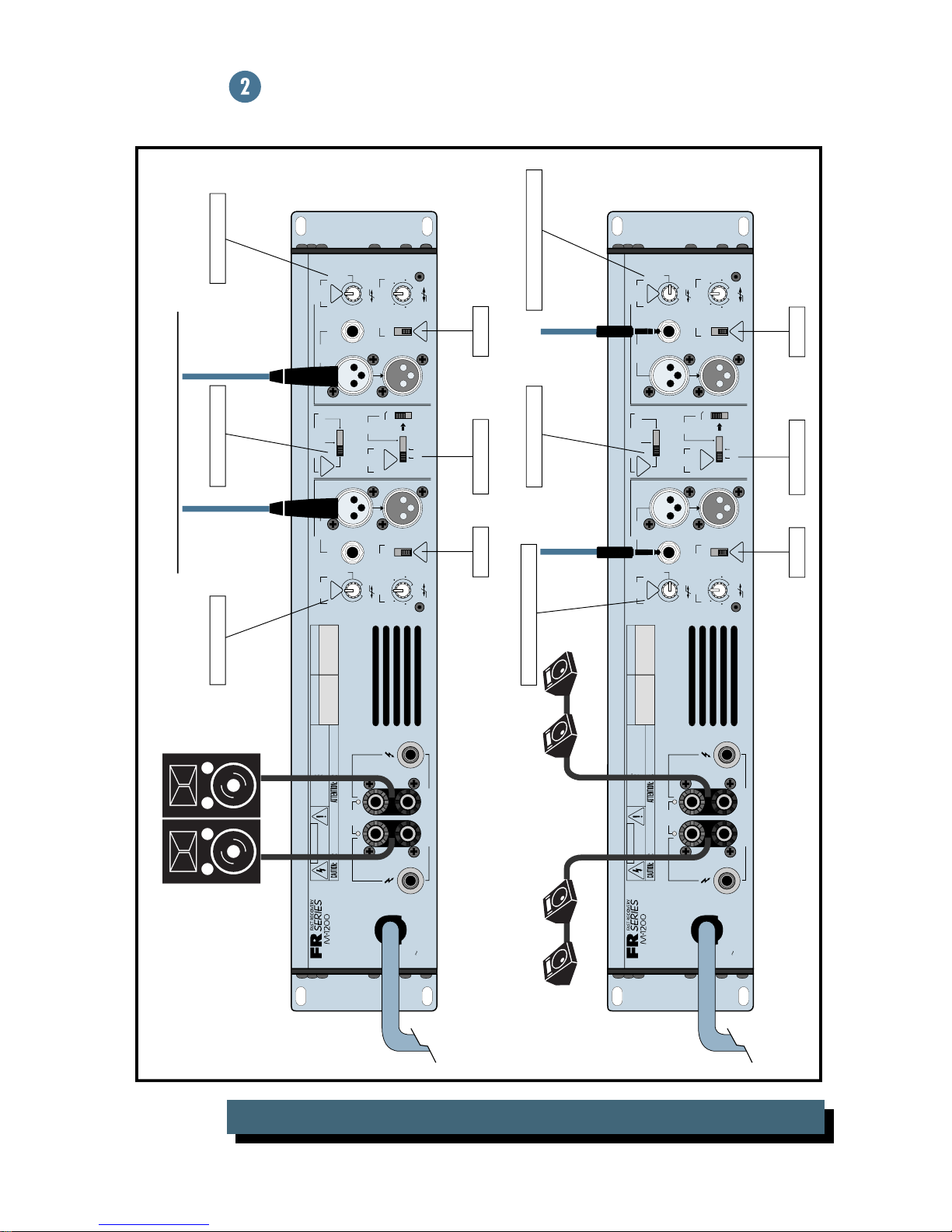
8
TWO M•1200S: MAIN SPEAKERS AND ST AGE MONITORS
FROM MIXING CONSOLE
MAIN OUT
FROM MIXING CONSOLE
MONITOR OUT
TYPICAL 35Hz STEREO/TYPICAL
/ BRIDGE/ MONO
CHANNEL
1
OFF
2k Hz
LOW CUT
FILTER
TYPICAL
35 Hz
STAGE
MONITOR
100 Hz
170 Hz
CONSTANT DIRECTIVITY
HORN EQ/AIR EQ
4.5 k Hz
5.6k Hz
AIR EQ
BALANCED
UNBALANCED
INPUT
OR
ON
OFF
TYPICAL
AMP MODE
MONO
STEREO
TYPICAL
OUTPUT APPLICATION
FULL
RANGE
LIMITER
(CH1 & CH2)
STEREO
TYPICAL
OFF
ON
WOOFER
BRIDGE
SUB
FREQUENCY
125Hz
63Hz
THRUTHRU
(MONO BRIDGE)
1400 WATTS
4 OHM LOAD MIN.
700 WATTS CH
2 OHMS LOAD MIN.
120 VAC 50/60 Hz
1500 WATTS
CAUTION
RISK OF ELECTRIC SHOCK
DO NOT OPEN
REPLACE WITH THE SAME TYPE FUSE AND RATING.
DISCONNECT SUPPLY CORD BEFORE CHANGING FUSE
CH
1
+
MONO
BRIDGE
+
SPEAKER OUTPUTS
WARNING:
TO REDUCE THE RISK OF FIRE OR ELECTRIC SHOCK, DO NOT
EXPOSE THIS EQUIPMENT TO RAIN OR MOISTURE. DO NOT REMOVE COVER.
NO USER SERVICEABLE PARTS INSIDE. REFER SERVICING TO QUALIFIED PERSONNEL.
AVIS:
RISCQUE DE CHOC ÉLECTRIQUE — NE PAS OUVRIR
UTILISE UN FUSIBLE DE RECHANGE DE MÊME TYPE.
DEBRANCHER AVANT DE REMPLACER LE FUSIBLE
CH
–
2
+
––
MANUFACTURING DATE
SERIAL NUMBER
CONCEIVED, DESIGNED, AND MANUFACTURED
BY MACKIE DESIGNS INC • WOODINVILLE • WA
98072 • USA • MADE IN USA • PATENTS PENDING
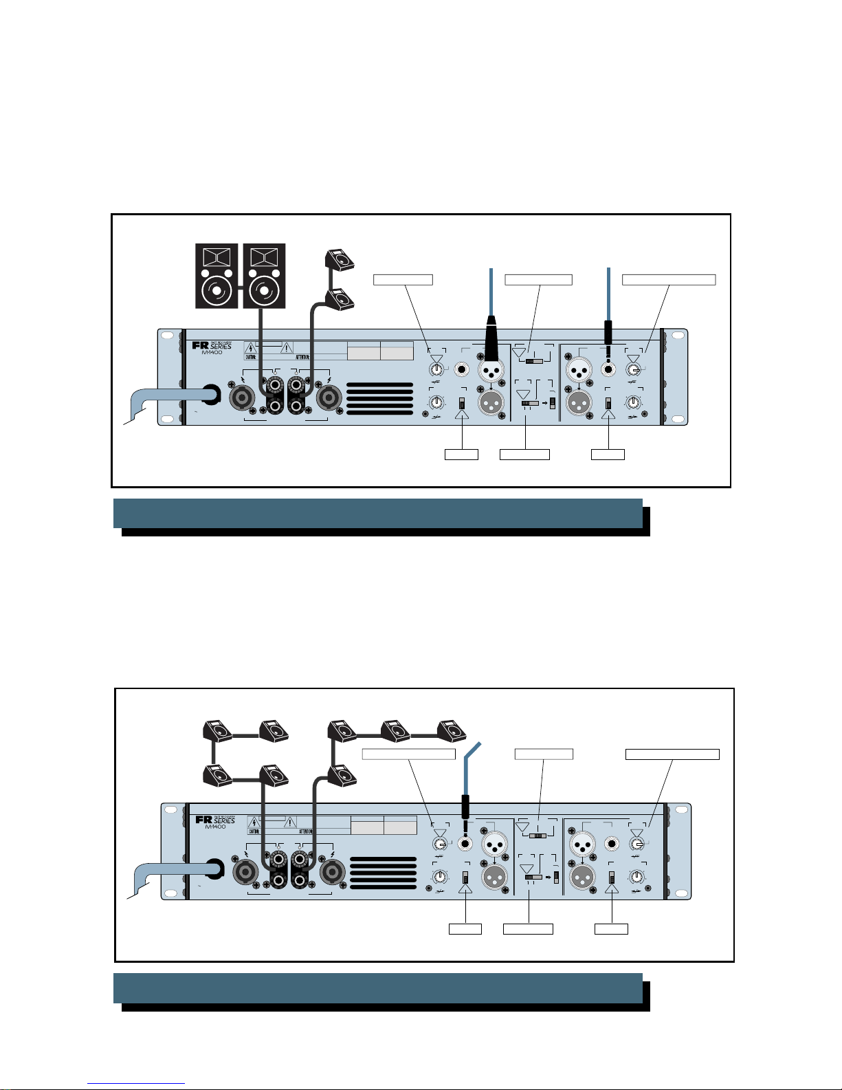
LIMITER ONCD OFF CD OFF
M•1400: MAIN SPEAKERS AND ST AGE MONITORS WITH ONE AMPLIFIER
STAGE MONITOR 100Hz
CHANNEL
INPUT
BALANCED
OR
UNBALANCED
OFF
CONSTANT DIRECTIVITY
HORN EQ/AIR EQ
ON
2k Hz
OFF
TYPICAL
LOW CUT
2
FILTER
TYPICAL
35 Hz
STAGE
MONITOR
100 Hz
170 Hz
4.5k Hz
5.6k Hz
AIR EQ
* SEE NOTE BELOW
CAUTION
RISK OF ELECTRIC SHOCK
DO NOT OPEN
REPLACE WITH THE SAME TYPE FUSE AND RATING.
(MONO BRIDGE)
1400 WATTS
4 OHM LOAD MIN.
700 WATTS CH
2 OHMS LOAD MIN.
DISCONNECT SUPPLY CORD BEFORE CHANGING FUSE
CH
1
+
+
120 VAC 50/60 Hz
1500 WATTS
* NOTE: TOTAL IMPEDANCE MUST BE GREATER
THAN 2 OHMS PER CHANNEL
SPEAKER OUTPUTS
M•1400: EIGHT MONITOR SPEAKERS
WARNING:
EXPOSE THIS EQUIPMENT TO RAIN OR MOISTURE. DO NOT REMOVE COVER.
NO USER SERVICEABLE PARTS INSIDE. REFER SERVICING TO QUALIFIED PERSONNEL.
AVIS:
RISCQUE DE CHOC ÉLECTRIQUE — NE PAS OUVRIR
MONO
BRIDGE
–
+
––
TO REDUCE THE RISK OF FIRE OR ELECTRIC SHOCK, DO NOT
UTILISE UN FUSIBLE DE RECHANGE DE MÊME TYPE.
DEBRANCHER AVANT DE REMPLACER LE FUSIBLE
CH
2
MANUFACTURING DATE
SERIAL NUMBER
CONCEIVED, DESIGNED, AND MANUFACTURED
BY MACKIE DESIGNS INC • WOODINVILLE • WA
98072 • USA • MADE IN USA • PATENTS PENDING
1
CHANNEL
OFF
2k Hz
LOW CUT
/ BRIDGE/ MONO
FILTER
TYPICAL
35 Hz
STAGE
MONITOR
100 Hz
170 Hz
CONSTANT DIRECTIVITY
HORN EQ/AIR EQ
4.5 k Hz
5.6k Hz
AIR EQ
FROM MIXING CONSOLE
MONITOR OUT
INPUT
BALANCED
OR
UNBALANCED
ON
OFF
TYPICAL
MONO MODE
AMP MODE
STEREO
TYPICAL
OUTPUT APPLICATION
FULL
RANGE
LIMITER
(CH1 & CH2)
STEREO
TYPICAL
OFF
ON
LIMITER ONCD OFF
STAGE MONITOR 100HzSTAGE MONITOR 100Hz
CHANNEL
2
LOW CUT
MONO
BRIDGE
SUB
WOOFER
FREQUENCY
INPUT
125Hz
63Hz
THRUTHRU
BALANCED
UNBALANCED
TYPICAL
OR
CONSTANT DIRECTIVITY
HORN EQ/AIR EQ
ON
OFF
FILTER
TYPICAL
35 Hz
STAGE
MONITOR
100 Hz
170 Hz
OFF
4.5k Hz
2k Hz
5.6k Hz
AIR EQ
CD OFF
9
CONSTANT DIRECTIVITY HORNS
CAUTION
WARNING:
TO REDUCE THE RISK OF FIRE OR ELECTRIC SHOCK, DO NOT
EXPOSE THIS EQUIPMENT TO RAIN OR MOISTURE. DO NOT REMOVE COVER.
NO USER SERVICEABLE PARTS INSIDE. REFER SERVICING TO QUALIFIED PERSONNEL.
RISK OF ELECTRIC SHOCK
DO NOT OPEN
AVIS:
RISCQUE DE CHOC ÉLECTRIQUE — NE PAS OUVRIR
(MONO BRIDGE)
1200 WATTS
4 OHM LOAD MIN.
600 WATTS CH
2 OHMS LOAD MIN.
120 VAC 50/60 Hz
1500 WATTS
REPLACE WITH THE SAME TYPE FUSE AND RATING.
DISCONNECT SUPPLY CORD BEFORE CHANGING FUSE
CH
1
+
MONO
BRIDGE
+
SPEAKER OUTPUTS
–
UTILISE UN FUSIBLE DE RECHANGE DE MÊME TYPE.
DEBRANCHER AVANT DE REMPLACER LE FUSIBLE
+
––
CH
2
MANUFACTURING DATE
SERIAL NUMBER
CONCEIVED, DESIGNED, AND MANUFACTURED
BY MACKIE DESIGNS INC • WOODINVILLE • WA
98072 • USA • MADE IN USA • PATENTS PENDING
FROM ACTIVE CROSSOVER: HIGH-FREQUENCY L/R
STEREO/TYPICAL
/ BRIDGE/ MONO
CHANNEL
1
LOW CUT
FILTER
TYPICAL
35 Hz
OFF
CONSTANT DIRECTIVITY
HORN EQ/AIR EQ
4.5 k Hz
2k Hz
5.6k Hz
AIR EQ
INPUT
BALANCED
OR
UNBALANCED
STAGE
MONITOR
100 Hz
170 Hz
ON
OFF
TYPICAL
AMP MODE
STEREO
TYPICAL
OUTPUT APPLICATION
FULL
RANGE
LIMITER
(CH1 & CH2)
STEREO
TYPICAL
OFF
ON
MONO
BRIDGE
SUB
WOOFER
FREQUENCY
125Hz
63Hz
THRUTHRU
CHANNEL
LOW CUT
INPUT
BALANCED
OR
UNBALANCED
OFF
CONSTANT DIRECTIVITY
HORN EQ/AIR EQ
ON
2k Hz
OFF
TYPICAL
170Hz170Hz
2
FILTER
TYPICAL
35 Hz
STAGE
MONITOR
100 Hz
170 Hz
4.5k Hz
5.6k Hz
AIR EQ
LOW-FREQUENCY
CABINETS
CAUTION
WARNING:
EXPOSE THIS EQUIPMENT TO RAIN OR MOISTURE. DO NOT REMOVE COVER.
NO USER SERVICEABLE PARTS INSIDE. REFER SERVICING TO QUALIFIED PERSONNEL.
RISK OF ELECTRIC SHOCK
DO NOT OPEN
AVIS:
+
SPEAKER OUTPUTS
RISCQUE DE CHOC ÉLECTRIQUE — NE PAS OUVRIR
MONO
BRIDGE
+
–
+
––
REPLACE WITH THE SAME TYPE FUSE AND RATING.
(MONO BRIDGE)
1400 WATTS
4 OHM LOAD MIN.
700 WATTS CH
2 OHMS LOAD MIN.
120 VAC 50/60 Hz
1500 WATTS
* CD HORN EQ FREQUENCY SETTING DEPENDS
ON COMPRESSION DRIVER/CD HORN COMBINATION
DISCONNECT SUPPLY CORD BEFORE CHANGING FUSE
CH
1
M•1200/M•1400: STEREO SYSTEM WITH CD HORNS
FULL
RANGE
WARNING:
CAUTION
EXPOSE THIS EQUIPMENT TO RAIN OR MOISTURE. DO NOT REMOVE COVER.
NO USER SERVICEABLE PARTS INSIDE. REFER SERVICING TO QUALIFIED PERSONNEL.
RISK OF ELECTRIC SHOCK
DO NOT OPEN
AVIS:
+
SPEAKER OUTPUTS
RISCQUE DE CHOC ÉLECTRIQUE — NE PAS OUVRIR
MONO
BRIDGE
+
–
+
––
(MONO BRIDGE)
1200 WATTS
4 OHM LOAD MIN.
600 WATTS CH
2 OHMS LOAD MIN.
120 VAC 50/60 Hz
1500 WATTS
REPLACE WITH THE SAME TYPE FUSE AND RATING.
DISCONNECT SUPPLY CORD BEFORE CHANGING FUSE
CH
1
TO REDUCE THE RISK OF FIRE OR ELECTRIC SHOCK, DO NOT
UTILISE UN FUSIBLE DE RECHANGE DE MÊME TYPE.
DEBRANCHER AVANT DE REMPLACER LE FUSIBLE
CH
2
TO REDUCE THE RISK OF FIRE OR ELECTRIC SHOCK, DO NOT
UTILISE UN FUSIBLE DE RECHANGE DE MÊME TYPE.
DEBRANCHER AVANT DE REMPLACER LE FUSIBLE
CH
2
*3.5KHz
CD ON
LIMITER ON
FROM ACTIVE CROSSOVER: LOW-FREQUENCY L/R
TYPICAL 35Hz TYPICAL 35Hz
SERIAL NUMBER
CONCEIVED, DESIGNED, AND MANUFACTURED
BY MACKIE DESIGNS INC • WOODINVILLE • WA
98072 • USA • MADE IN USA • PATENTS PENDING
1
LOW CUT
FILTER
BALANCED
OR
TYPICAL
UNBALANCED
35 Hz
STAGE
MONITOR
100 Hz
170 Hz
OFF
CONSTANT DIRECTIVITY
HORN EQ/AIR EQ
4.5 k Hz
ON
2k Hz
5.6k Hz
OFF
AIR EQ
TYPICAL
/ BRIDGE/ MONO
CHANNEL
MANUFACTURING DATE
CD OFF CD OFF
INPUT
STEREO/TYPICAL
AMP MODE
MONO
BRIDGE
STEREO
TYPICAL
OUTPUT APPLICATION
SUB
FULL
WOOFER
RANGE
LIMITER
(CH1 & CH2)
FREQUENCY
STEREO
TYPICAL
125Hz
63Hz
OFF
ON
LIMITER ON
INPUT
BALANCED
OR
UNBALANCED
CONSTANT DIRECTIVITY
HORN EQ/AIR EQ
ON
OFF
TYPICAL
THRUTHRU
FROM MIXING CONSOLE MAIN OUT L/R
130Hz STEREO/TYPICAL 130Hz
/ BRIDGE/ MONO
CHANNEL
MANUFACTURING DATE
SERIAL NUMBER
CONCEIVED, DESIGNED, AND MANUFACTURED
BY MACKIE DESIGNS INC • WOODINVILLE • WA
98072 • USA • MADE IN USA • PATENTS PENDING
1
LOW CUT
FILTER
TYPICAL
35 Hz
OFF
CONSTANT DIRECTIVITY
HORN EQ/AIR EQ
4.5 k Hz
2k Hz
5.6k Hz
AIR EQ
INPUT
BALANCED
OR
UNBALANCED
STAGE
MONITOR
100 Hz
170 Hz
ON
OFF
TYPICAL
AMP MODE
STEREO
TYPICAL
OUTPUT APPLICATION
FULL
RANGE
LIMITER
(CH1 & CH2)
STEREO
TYPICAL
OFF
ON
BRIDGE
FREQUENCY
INPUT
BALANCED
OR
UNBALANCED
CONSTANT DIRECTIVITY
125Hz
63Hz
HORN EQ/AIR EQ
ON
OFF
TYPICAL
THRUTHRU
MONO
SUB
WOOFER
*3.5KHzCD ON
CHANNEL
OFF
2k Hz
CHANNEL
OFF
2k Hz
2
LOW CUT
FILTER
TYPICAL
35 Hz
STAGE
MONITOR
100 Hz
170 Hz
4.5k Hz
5.6k Hz
AIR EQ
2
LOW CUT
FILTER
TYPICAL
35 Hz
STAGE
MONITOR
100 Hz
170 Hz
4.5k Hz
5.6k Hz
AIR EQ
SUBWOOFERS
(MONO BRIDGE)
1400 WATTS
4 OHM LOAD MIN.
700 WATTS CH
2 OHMS LOAD MIN.
120 VAC 50/60 Hz
1500 WATTS
CH
1
M•1200/M•1400: STEREO SYSTEM WITH BRIDGED SUBWOOFER
10
CAUTION
RISK OF ELECTRIC SHOCK
DO NOT OPEN
REPLACE WITH THE SAME TYPE FUSE AND RATING.
DISCONNECT SUPPLY CORD BEFORE CHANGING FUSE
MONO
BRIDGE
+
+
SPEAKER OUTPUTS
WARNING:
TO REDUCE THE RISK OF FIRE OR ELECTRIC SHOCK, DO NOT
EXPOSE THIS EQUIPMENT TO RAIN OR MOISTURE. DO NOT REMOVE COVER.
NO USER SERVICEABLE PARTS INSIDE. REFER SERVICING TO QUALIFIED PERSONNEL.
AVIS:
RISCQUE DE CHOC ÉLECTRIQUE — NE PAS OUVRIR
UTILISE UN FUSIBLE DE RECHANGE DE MÊME TYPE.
DEBRANCHER AVANT DE REMPLACER LE FUSIBLE
CH
–
2
+
––
LIMITER ONCD OFF CD OFF
20Hz BRIDGE MODE 20Hz
/ BRIDGE/ MONO
CHANNEL
MANUFACTURING DATE
SERIAL NUMBER
CONCEIVED, DESIGNED, AND MANUFACTURED
BY MACKIE DESIGNS INC • WOODINVILLE • WA
98072 • USA • MADE IN USA • PATENTS PENDING
1
LOW CUT
FILTER
TYPICAL
35 Hz
OFF
CONSTANT DIRECTIVITY
4.5 k Hz
2k Hz
STAGE
MONITOR
100 Hz
170 Hz
HORN EQ/AIR EQ
5.6k Hz
AIR EQ
BALANCED
UNBALANCED
INPUT
OR
ON
OFF
TYPICAL
CD OFF CD OFF
AMP MODE
MONO
BRIDGE
STEREO
TYPICAL
OUTPUT APPLICATION
SUB
FULL
WOOFER
RANGE
LIMITER
(CH1 & CH2)
FREQUENCY
STEREO
TYPICAL
125Hz
63Hz
OFF
ON
SUBWOOFER MODE
@ 125Hz
THRUTHRU
CHANNEL
2
LOW CUT
INPUT
FILTER
BALANCED
TYPICAL
OR
35 Hz
UNBALANCED
STAGE
MONITOR
100 Hz
170 Hz
OFF
CONSTANT DIRECTIVITY
HORN EQ/AIR EQ
4.5k Hz
ON
2k Hz
5.6k Hz
AIR EQ
OFF
TYPICAL

FEATURE DESCRIPTIONS
GAIN
These giant knobs control the levels to the
output section of the M•1200/M•1400 amplifiers. Y ou’ll notice that their travel is detented,
meaning there are 40 built-in “resting points”
so you can easily set both controls to the same
level. Usually, these controls ar e set all the
way up.
The gain structure of the amplifier is designed so that a +4 dBu (1.23V rms) input
signal drives the amplifier to full rated power
into 4 ohms (40V rms @ 4 ohms = 400 watts for
the M•1200). This is how the sensitivity
of an amplifier is defined. In this case, it
equates to a voltage gain of about 30 dB (okay,
30.24 dB for those of you sittin’ there with your
calculator!).
The graphics around the knob depict two
different methods for setting the gain. The inner circle is marked in dB, calibrated from off
(∞) to 30. This r epresents the amount of voltage gain from input to output. When using
professional equipment with +4 dBu output
GAIN
levels, set the
The outer circle is labeled in volts, with indications of 1V , 2V, and 3V. These corr espond to
the input sensitivity of the amplifier . W ith the
GAIN
control all the way up (fully clockwise),
the input sensitivity is 1.23V , which works well
with professional equipment operating at a
nominal +4 dBu level.
On the other hand, you may want your listening level to be quieter than the M•1200/
M•1400’s maximum level. For instance, if
you’re using the M•1200/M•1400 as a control
room amp, and your control room is the size of
a telephone booth, you’ll probably never want
to hear the amp at its maximum level.
reach full power at the amplifier’s output.
See the sidebar “Constant Gain vs. Constant
Sensitivity” for a better understanding of how
this works.
Like all amplifier controls, you’ll typically
determine the optimal settings during installa-
control all the way up to 30.
GAIN
Y ou can set the
trols as low as you like.
However , r educing the
GAIN
controls requires an
increased input level to
con-
Constant Gain vs. Constant Sensitivity
There are two viewpoints, or philosophies,
regarding the gain structure of power amplifiers — constant gain and constant sensitivity.
Constant gain means that regardless of the
output power of the amplifier , the gain from input to output remains the same. (By the way,
this refers to the full gain of the amplifier, with
the gain or level controls all the way up.)
Within a product line of constant gain power
amplifiers, as the output power rating of an
amplifier increases, the level of the input voltage must also increase.
For example, if an amplifier is rated at
100W into an 8-ohm load, and it has 26 dB of
gain, it requires an input signal of 1.4V rms to
drive it to full power . This is about +5 dBu, a
reasonable operating point for professional
gear .
Now take an amplifier rated at 200W into an
8-ohm load. If it also has a gain of 26 dB, it requires an input signal of 2.0V rms to drive it to
full power , or +8 dBu.
This can become problematic as the power
of the amplifier increases. What if you have a
power amp rated at 800W into 8 ohms? This
will require an input signal of 4.0V rms to drive
it to full power . This equates to a whopping
+14.3 dBu!! Y ou’ve just robbed your mixer of
10 dB of headroom. Y ou’ll either have to have a
good limiter to keep the transient peaks down,
or turn down the level from the mixer and not
use all the power available from the amplifier .
Constant sensitivity means that regardless
of the output power of the amplifier , the input
sensitivity of the amplifier (the input voltage
required to attain full output power) remains
the same. As the output power of an amplifier
increases, the gain of the amplifier must also
increase.
Referring back to the previous example, an
amplifier rated at 100W into 8 ohms with a
gain of 26 dB requires an input signal of 1.4V
rms to drive it to full power . It has an input
sensitivity of 1.4V rms. In order for the 200W
amplifier to reach full power into 8 ohms with
a 1.4V rms input signal, it must have a gain of
29 dB. And the 800W amplifier will require a
gain of 35 dB to reach full power with a 1.4V
input signal.
Continued on page 12
11

So what are the pros and cons of these two
approaches? The reason some amplifier
manufacturers use the constant gain approach is because the noise specification
looks better . It’ s a fact of physics that as the
gain of the amplifier increases, the circuit
noise is amplified and increases too. By maintaining a constant gain, the noise spec for an
800W amplifier can look as good as the noise
spec for a 100W amplifier . The downside to
this is that you have to crank up your mixer
level feeding the input of the amplifier , losing
headroom and possibly increasing the noise
level from the mixer (unless you have a
Mackie mixer with low-noise VLZ circuitry!).
Conversely, constant sensitivity demands
that as the power increases, so must the gain.
Y es, the output noise of the amplifier will
increase, but you maintain the critical headroom available from your mixer. The additional noise is generally not a problem in live
sound reinforcement situations. If it is, you
GAIN
can turn down the
control a few clicks
to find a happy compromise between noise
floor and headroom available (see “Optimizing Sound System Levels” in Appendix D).
As an added benefit, you can drive multiple
amplifiers with the same signal and get the
maximum power available from all of them.
Mackie subscribes to the philosophy of
constant sensitivity. Our amplifiers can be
driven to full power with an input level of
+4 dBu (1.23V rms).
tion or sound check, then leave them alone,
using your signal source (usually a mixer) to
control listening levels as you work. Or play .
Y ou may wonder why we
didn’t use just one stereo
control to control both sides.
That’s in case your applica-
tion requires a left/right
imbalance (due to an irregularly shaped room)
or if you’re using the two sides for completely
different purposes (monitor in channel 1 and
side-fill in channel 2, for instance). Besides,
they look cool.
METERS
The M•1200/M•1400’s meters indicate the
relative output level of the amplifier refer enced to full power . The numbers next to the
meter’s LEDs are in dB below full power.
–20, –9
Ideally, the M•1200/M•1400’ s
–6,
and –3 LEDs will flicker at normal signal
OL
levels, while the
LED may flicker occasion-
ally during peak moments.
OL
is short for Overload. Overloading, or
clipping, occurs when the output voltage no
longer linearly follows the input voltage and
simply stops. This causes a sine wave to
“square off,” or get “clipped off.” Thus, the term
clipping. Fear not — this scenario is quite un-
GAIN
likely. Even with the
controls fully up,
the M•1200/M•1400 amplifiers easily accept
professional “+4 dBu” operating levels.
,
CH
1
12
GAIN/dB
18
14
8
SENSITIVITY
3v
20
0
0
FULL SYMMETRY DUAL DIFFERENTIAL HIGH CURRENT DESIGN
GAIN/dB
18
14
8
SENSITIVITY
3v
20
0
0
22
2416
26
28
30
1v
1.23v (+4dBu)
2v
22
2416
26
28
30
1v
1.23v (+4dBu)
OL
–3
2v
–6
–9
–20
–3
–6
–9
–20
SIGOLSIG
CH
CH
2
CH
1
INTERNAL STATUS
PROTECT
SHORT
TEMP STATUS
CH
1& 2
COLD HOT
2
If the OL (Overload) LED
is blinking frequently or
continuously, turn down
the source signal (i.e. the
mixer’s master faders).
SIG
SIG
(short for “signal present”) is the lowest
step in the meters’
prior to the
GAIN
ladder . It senses the signal
control, so when
SIG
is lit,
you know the M•1200/M•1400 is receiving signal.
If it’s the only meter LED lit (meaning the other
meter LEDs are not lit), the M•1200/M•1400 is
receiving a very weak signal (below –20 dB).
PROTECT
If the
PROTECT
M•1400’s output section has shut down. That,
of course, means you won’t hear anything until
you rectify the situation. Three things can
cause the
PROTECT
1. Powering up the M•1200/M•1400. A built-
in delay circuit saves your speakers (and
ears) from the thumps or pops that can
sometimes occur when powering up a
system. During this 3 second delay, the
PROTECT
2. A short circuit (or near short) in either of
the outputs. Both the
SHORT
LEDs light up.
3. The temperature in the M•1200/M•1400
has risen to an unsafe level. The
and the
LEDs are on, the M•1200/
circuit to engage:
LEDs light up.
PROTECT
TEMP STATUS
LEDs light up.
and the
PROTECT
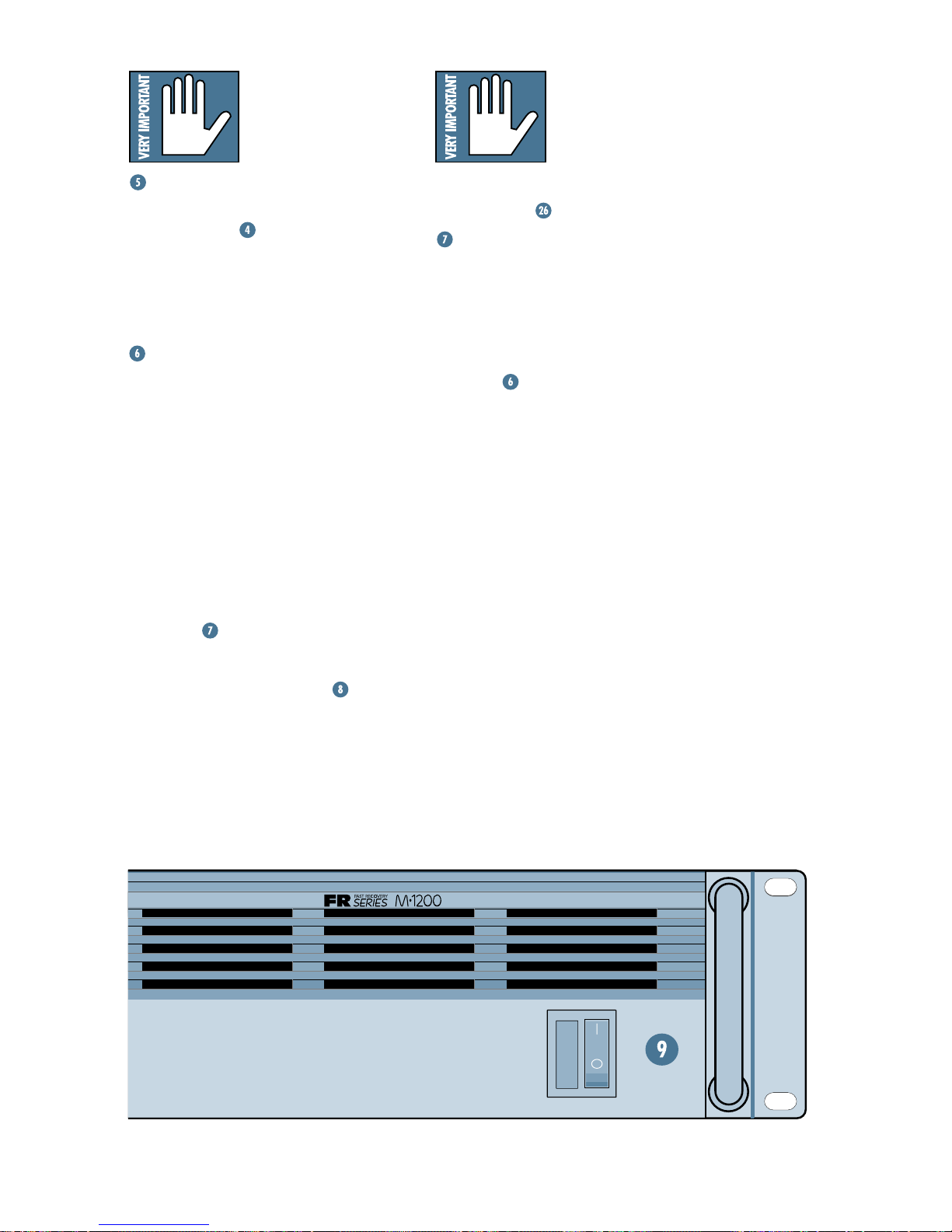
The M•1200/M•1400
amps draw their ventilation air in from the front
and out through the side
panels. The amp needs
plenty of fresh air to stay cool. DO NOT BLOCK
THE VENTILATION PORTS. See
Considerations”
.
“Thermal
SHORT
If this LED comes on, the M•1200 or
M•1400 has detected a short circuit in either
of the outputs, meaning that the hot (+) and
cold (–) speaker wires are touching, or a
speaker itself is shorted out. Such a condition
causes the M•1200/M•1400 to engage its
PROTECT
muting all signals at the amp’s outputs.
(until the other guys “borrow” the idea) and
can save precious minutes of your troubleshooting time. Without it, you’d still have
speaker and amp protection (via the
circuit), but you wouldn’t be able to determine
the source of the problem. But with the
LED, the M•1200/M•1400 comes right out and
tells you!
unsafe condition for the power amplifier . Once
the
off, wait for the indicator to extinguish, and
turn the power back on again to reset the amplifier .
be either a shorted speaker cable or too many
speaker cabinets connected to the amplifier
(i.e., the load impedance is too low). If a “short”
is indicated, please check your cables. If the
cabling is OK, then reduce the number of cabinets driven by the amplifier .
mode (when a signal is present),
This short-circuit LED is a Mackie exclusive
PROTECT
SHORT
SHORT
WARNING: The
SHORT
LED is lit, you must turn the power
LEDs indicate an
Typical causes for a “short” indication would
PROFESSIONAL POWER AMPLIFIER
ON
OFF
POWER
13
 Loading...