

Page 1

;?#'
;0:4?A>24BB>A20A3
DB4A½B6D834
Page 2

Contents
1.1 Introduction.................................................................3
Insert EQ Features ......................................................3
Lake Loudspeaker Processor Features ....................3
Getting Started ............................................................4
Installing the Card .......................................................4
Updating the Software ................................................4
Opening the LP48 Setup Screen ................................4
2. Modes of Operation .....................................................6
Overview ......................................................................7
LP48 Card Outputs ......................................................7
3. Lake EQ Mode (10 Insert Equalizers) .......................8
Source Assign ..............................................................8
Low-shelf EQ .............................................................11
Parametric EQ ...........................................................11
High-shelf EQ .............................................................12
Parametric EQ ...........................................................13
Mesa EQ .....................................................................14
Button Bar ..................................................................15
Home ...........................................................................15
Overlay Functions .....................................................15
Overlay GEQ ..............................................................15
Overlay PEQ ..............................................................16
EQ Preferences ..........................................................16
4. Lake Loudspeaker Processor Mode (4x8) .............18
Source Assign ............................................................18
4.1 Home ..........................................................................20
4.2 System Store/Recall..................................................21
4.3 Modules ......................................................................23
Default Modules ........................................................28
Two Auxiliary Outputs ..............................................30
XOVER Tab ................................................................32
Levels Tab ..................................................................39
4.4 Groups .........................................................................44
Gang ............................................................................49
4.5 Solo/Mute ....................................................................50
4.6 User Preferences .......................................................51
4.7 Icon Control ...............................................................53
5. Introduction to Designer Mode ...............................54
6. Functional Reference Guide ....................................63
Need help with your new LP48 Card?
• Visit www.mackie.com and click Support
to fi nd: FAQs, manuals, addendums, and
other useful information.
• Email us at: techmail@mackie.com.
• Telephone 1-800-898-3211 to speak with
one of our splendid technical support
chaps, (Monday through Friday, from 7
a.m. to 5 p.m. PST).
Part No. SW0726 Rev. A 09/08
©2008 LOUD Technologies Inc. All Rights Reserved.
2
Page 3

1. Introduction
Thank you for choosing to upgrade your TT24 Digital Live Mixing Console with the LP48 Lake Processor
expansion card. Dolby Laboratories designed the highly regarded Lake Contour™ Digital Loudspeaker processor,
and worked with us here at Mackie to develop the fi rst integrated Lake EQ and Lake Loudspeaker modules for a
digital console.
The TT24 with an LP48 expansion card provides 10 channels of Lake Insert EQ processing, or eight channels of
Lake Loudspeaker processing, or a combination of the two (fi ve channels of EQ processing and four channels of
Lake Loudspeaker processing).
The inputs to the LP48 are assigned in the TT Control software application running on your PC from virtually
any point in the TT24 signal path. The loudspeaker processor outputs from the LP48 card can be routed to any
physical output connector on the console or the DS3232 Digital Snake.
LP48 confi guration is done within the TT Control software Setup>Expansion menu.
Insert EQ Features
The Lake EQ Mode provides ten EQ processors that can be inserted into any of the TT24 digital insert points.
Each EQ processor can operate with the Lake Ideal Graphic EQ (28-bands) or the Lake Mesa EQ (parametric
EQ).
Unlike standard graphic equalizers whose adjacent fi lters interact and add to each other, the Lake Ideal Graphic
EQ provides a frequency response curve exactly like the curve of the user interface sliders. This allows you to
have more precise control over your sound. What you see is what you get!
Lake Loudspeaker Processor Features
The Lake Loudspeaker Processor Mode provides a four input by eight output speaker processor (two input by
four output when in split mode). It has two DSP engines that split up the work between them.
In split mode, you can confi gure the processor as follows:
• Two two-way crossovers
• One three-way crossover
• One four-way crossover
• Two Aux mode
When the whole card is confi gured in Lake
Loudspeaker Processor mode, you can confi gure the
processors as follows:
• Four two-way crossovers
• One four-way crossover and one three-way
• One four-way crossover and two two-way
• Two four-way crossovers
• Two three-way crossovers
• Two Aux mode
You can select from the following crossover types for each individual crossover fi lter, using fi lter orders from
6 dB/octave up to 48 dB/octave:
2 Aux mode
A
1
2
2-way
Xover
A
2-way
Xover
B
C
2-way
Xover
D
2-way
Xover
1
2
3
4
5
6
7
8
3-way
Xover
A
B
C
3-way
D
Xover
1
2
3
4
5
6
7
8
4-way
Xover
A
B
C
D
4-way
Xover
1
2
3
4
5
6
7
8
• Bessel
• Butterworth
• Linkwitz-Riley
Important default presets allow you to set up and change between the various crossover types. Presets for EAW
and Mackie loudspeakers are also provided.
3
Page 4

Getting Started
Installing the Card
The fi rst thing to do is to install the LP48 expansion card into your TT24. See the “TT24 Expansion Card
Installation Instructions” that came with your LP48 for instructions on how to install the expansion card.
Updating the Software
The next thing is to make sure you have the latest fi rmware for the TT24 and the latest TT Control software
application for your PC. Version 1.7 or greater is required to run the LP48 card.
If you don't know the software version you are currently using, you can check your software ver sion and build
number by pressing the “HELP” button on the console,
application.
You can fi nd the latest version of the TT24 fi rmware and TT Control PC application on the Mackie website:
http://www.mackie.com/products/tt24/software.html
Be sure to follow the instructions when upgrading to new software, as described in the TT24 Firmware/Software
Installation guide found in the link.
It is VERY IMPORTANT that you always update the fi rmware in the following order:
1. DS3232 Digital Snake (if present)
or by clicking Menu > About in the TT Control PC
2. Expansion Cards (if present)
3. The TT24 Console.
Opening the LP48 Setup Screen
Now you have installed the LP48 expansion card and updated the fi rmware and
software, you are ready to turn on the TT24 and start confi guring the LP48 Lake
Processor Card.
To confi rm that the LP48 card is installed and properly recognized:
1. Press the SETUP button in the QuickMix area.
2. Touch the EXPANSION button in the MENU SELECTION window.
SETUP
SNAPSHOTS
SETUP
CTRL
COPY
RECALL
STORE
HELP
UTIL
PAS TE
4
Page 5

3. The EXPANSION window displays the cards installed in the two expansion slots on the TT24. That’s as far as
you can go on the TT24 Touchscreen. All the configurations for the LP48 are done through the TT Control PC
application.
4. Connect a USB cable between the TT24 and your computer.
5. Open the TT Control PC application on your computer.
6. If the Expansion window isn’t open yet, press F11 on the keyboard to open the Expansion window.
7. Click the EDIT button at the bottom of the expansion slot window.
EDIT
8. This is your window into the amazing world of Lake processing, where you can access all the tools provided
by this powerful software and expansion card.
Snapshots Warning
The LP48 card has its own Snapshot Backup and Snapshot Restore
items available in the Menu>Expansion Card Options drop-down
menu of the TT Control software.
Make sure that you backup your LP48 Card Snapshots
when you backup your console, or the LP48 will not be
backed up.
NOTE: The LP48 snapshot backup and snapshot recall
process can take a long time, such as 30 minutes or so!!!
5
Page 6

2. Modes of Operation
Overview
There are three Card Modes from which to choose in the Lake Card Edit window: 10 Insert Equalizers, 4x8
Speaker Processor, and 2x4 Speaker Processor with 5 Insert EQs. Select the mode of operation you want to use
from the window shown below. If you make a change, you will be prompted to confi rm your choice:
10 Insert Equalizers
4x8 Speaker Processor
2x4 Speaker Processor
with 5 Insert EQs
6
Page 7

10 INSERT EQUALIZERS
Lake EQ Mode
When this mode of operation is selected, the LP48 supplies up to ten 1/3-octave graphic equalizers or parametric
equalizers, each of which can be inserted into the pre- or post-inserts for each channel (Analog 1-24 pre or post,
Digital 25-48 pre or post, card return 1-8 pre or post), the insert for an aux send (Aux Send 1-12), or the insert
for the Main Left, Right, or Mono output.
The Lake Ideal Graphic EQ™ provides tighter fi lter control over traditional analog (and digital) graphic EQs. It
features “raised cosine” algorithms that provide a frequency response that truly matches the curve established on
the graphic interface.
If one were to the boost a conventional graphic equalizer by 6 dB at 500, 750, 1000, 1250, 1600, and 2000 Hz,
the resulting frequency response would resemble the wavy curve in the top trace of the illustration below. The
bottom trace shows that the same adjacent fi lters in the Lake Ideal Graphic EQ sum to a fl at frequency response,
providing a response curve just like the one you expect when you adjust the Graphic EQ sliders.
The Lake Mesa EQ™ offers the classic shelving and parametric fi lters of traditional parametric EQs. But it goes
one step further by providing asymmetric fi ltering for independent control over upward and downward slopes of
a parametric fi lter section. This is particularly useful when performing corrective adjustments to the asymmetric
response patterns of all loudspeakers.
4x8 SPEAKER PROCESSOR
Lake Loudspeaker Processor Mode (4x8)
When this mode is selected, the LP48 provides four 1x2 crossover modules, each accepting an input from an aux
send (Aux Send 1-12), Matrix Out (Matrix A-H), or the Main Left, Right, or Mono output.
can also be confi gured as 1x3 (3-way) or 1x4 (4-way) crossovers, or a 1-input, 2-aux preset can be chosen.
Each input and output has a delay function for time alignment of delay stacks and drivers. In addition, each
output has a limiter function to provide protection for each driver. An extensive library of presets are provided,
tailored for many popular loudspeaker systems, including EAW and Mackie loudspeaker products.
The crossover modules
2x4 SPEAKER PROCESSOR with 5 INSERT EQs
Split Mode (2x4 Lake Loudspeaker Processor with 5 Lake Insert EQs)
This mode provides a combination of the fi rst two modes: two 1x2 crossover modules and fi ve insert EQ modules.
The features remain the same for each type, only the number of modules has been reduced by half for each type.
Refer to this manual’s sections regarding Lake EQ Mode and Lake Loudspeaker Processor Mode for an
explanation of each of the modes contained within Split Mode.
LP48 Card Outputs
For Inserts EQs, the processed output from the card is routed to the insert point. For Loudspeaker Processor
outputs, the output from the LP48 card (either 8, or 4 in split mode) can be routed using the TT Control Routing
Output screen of software version 1.7 or greater.
7
Page 8

3. Lake EQ Mode (10 Insert Equalizers)
When this mode is selected, you can choose between a 28-band graphic EQ (Lake Ideal Graphic EQ) or a fullfeatured parametric EQ (Lake Mesa EQ) for each insert.
Source Assign
You must assign a source for each insert EQ. You can select from any analog input (1-24 pre/post), digital input
(25-48 pre/post), card channel (1-8 pre/post), aux send (1-12 post), or the main left, right, or mono outputs
(post). Since these are insert points, the processed signal is returned to the signal path at the selected insert
point.
Edit
Click the EDIT button to open the EQ Edit window. This is where you select either the graphic EQ or parametric
EQ, and confi gure the various parameters of the equalizer.
EDIT
NOTE: After clicking EDIT, there may be a warning that the graphics need to be 16 bit. Usually it is OK to ignore
this warning, but if you have any trouble then adjust your computer display to suit.
8
Page 9

The parametric EQ is the default selection when you enter the EQ Edit window. The EQ Edit window consists of a
graph, with the x-axis (horizontal) representing frequency, and the y-axis (vertical) representing amplitude. The
icons at the top of the graph represent a low-shelf EQ, parametric EQ, Mesa EQ, and high-shelf EQ. The
the bottom of the graph provide access to other EQ options.
To confi gure the parametric EQ, simply click one of the blue icons at the top of the graph and move it to the
approximate point in the graph where you want it to be, then click again to place it.
buttons at
EQ Edit Window
Frequency Lock
This button, located in the upper left corner of the graph, locks the frequency of the selected fi lter so it cannot
be changed by clicking within the graph area. You will have to click below the graph.
mode as well, since you can adjust the cut or boost without accidentally moving to the next fi lter along.
This is useful in graphic EQ
9
Page 10

Button Menus used in Insert EQ mode
The LP48 uses a row of buttons along the bottom to choose and navigate within menu items.
This map shows the general layout of the button menus and their submenus for the Insert EQ mode. For
example, clicking on the Home button takes you to the top level. Clicking on Overlay Functions takes you to
another world of enchantment where you can select from graphic EQ or Parametric EQ, select EQ display
preferences, or copy and paste an EQ overlay.
Selectable buttons are blue.
Buttons that lead to sub-menus turn orange when selected.
Non-selectable buttons are grey (for example Filter Delete is not selectable for the graphic EQ).
Home
Overlay Functions
Overlay GEQ/Overlay PEQ
EQ Preferences
No Scale
Reset Scale
Zoom In
Zoom Out
Up
Down
Overlay Copy
Overlay Paste
Overlay Bypass
Overlay Flat
10
Filter Bypass
Filter Flat
Filter Delete
Filter Edit
Page 11

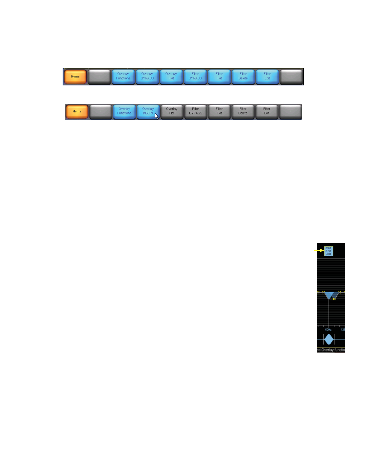
Parametric EQ
Click on Overlay Functions and select the Overlay PEQ button (if it is not already in that mode).
The operations that follow can be made no matter which row of buttons is displayed, even Home, but you need to
get into the Overlay Functions menu to change from GEQ to PEQ.)
Low-shelf EQ
Click the low-shelf EQ icon at the top of the work area (it
glows orange) and move it to the area of 0 dB, 100 Hz on the
graph, then click again to place it.
The icon appears at the bottom of the graph and the
parameters appear at the top of the graph (frequency, Q, and
amplitude).
Click the blue icon at the bottom of the graph and move it
left or right to adjust the cutoff frequency of the fi lter.
Click the vertical bar at the right tip of the icon and move it
left or right to adjust the slope (Q) of the fi lter.
Click the horizontal bar (0 dB) in the graph and move it up
or down to adjust the amplitude of the fi lter.
11
Page 12

High-shelf EQ
Click the high-shelf EQ icon (it glows orange) and move it
to the area of 0 dB, 10 kHz on the graph, then click again to
place it.
The icon appears at the bottom of the graph and the
parameters appear at the top of the graph (frequency, Q, and
amplitude).
Notice that the low-shelf EQ icon disappears from the
bottom of the graph, and an “X” appears in the graph. This
indicates that there is a fi lter located at that frequency.
Simply click on or below the “X” to select it or click on the
blue box above the X, and readjust the parameters if desired.
Click in the blue icon at the bottom of the graph and move it
left or right to adjust the cutoff frequency of the fi lter.
Click on the vertical bar at the left tip of the icon and move it
left or right to adjust the slope (Q) of the fi lter.
Click on the horizontal bar (0 dB) in the graph and move it
up or down to adjust the amplitude of the fi lter.
12
Page 13

Parametric EQ
Click the parametric EQ icon (it glows orange) and drag it to
the area of 1 kHz on the graph, then click again to place it.
The icon appears at the bottom of the graph and the
parameters appear at the top of the graph (frequency, Q, and
amplitude).
Notice that the high-shelf EQ icon disappears from the
bottom of the graph, and an “X” appears in the graph. This
indicates that there is a fi lter located at that frequency.
Simply click on the “X” to select it and readjust the
parameters, if desired.
Click inside the blue icon at the bottom of the graph and
move it left or right to adjust the center frequency of the
fi lter.
Click to the left or right of the vertical bar at either tip of the
icon and move it left or right to adjust the slope (Q) of the
fi lter. Note this adjusts the slope at both ends of the fi lter
symmetrically.
Click on the horizontal bar (0 dB) in the graph and move it
up or down to adjust the amplitude of the fi lter.
13
Page 14

Mesa EQ
The Mesa EQ is similar to the parametric EQ, except that
the bandwidth of the fi lter and the slope at both sides
of the fi lter envelope can be adjusted independently.
This allows you to tailor the fi lter for complex frequency
response corrections required for certain loudspeaker/room
combinations.
The icon appears at the bottom of the graph and the
parameters appear at the top of the graph (frequency, Q, and
amplitude of each end of the fi lter envelope).
Click inside the blue icon at the bottom of the graph and
move it left or right to adjust the center frequency of the
fi lter.
Click and move inside either tapered end of the blue icon to
increase or decrease the bandwidth.
Click to the left of the left tip of the icon and move it left or
right to adjust the slope (Q) of the low end of the fi lter.
Click to the right of the right tip of the icon and move it left
or right to adjust the slope (Q) of the high end of the fi lter.
Click on the horizontal bar (0 dB) in the graph and move it
up or down to adjust the amplitude of the fi lter.
14
Page 15

Button Bar
The buttons at the bottom of the EQ Edit window provide access to EQ options.
Home
Click this button to quickly return to the default EQ Edit screen.
Overlay Functions
Click this button and the other buttons will change function. These options allow you to change to the 28-band
Graphic EQ, to change EQ preferences, and to copy/paste EQ settings.
Overlay GEQ
Click this button to switch to a graphic EQ instead of a parametric EQ. A warning message asks you to confi rm
that you want to change to the graphic EQ overlay and lose the current EQ settings. Click “Yes” to switch to the
graphic EQ overlay.
Note: You cannot “undo” this action.
Each yellow “X” on the horizontal line (0 dB) represents a fi lter. You can click on an “X” to select it, or click and
drag across the bottom horizontal bar to access each individual graphic EQ fi lter.
Click on each “X” and drag up or down to adjust the amplitude (boost or cut) for each fi lter. The frequency and
slope for each fi lter are fi xed, and not adjustable.
Frequency Lock
If you click this button in the top left corner, then the fi lters cannot be selected by clicking on, above, or below
the yellow Xs. To select a different frequency, move the blue fi lter icon along the bottom of the screen left or
right.
If this is not engaged, then fi lters can be selected by clicking on, above, or below the yellow Xs.
15
Page 16

Overlay PEQ
Click this button to switch back to a parametric EQ from the graphic EQ. Once again, you will get a warning
message to confi rm that you want to change to the parametric EQ overlay and lose the current EQ settings. Click
“Yes” to switch to the parametric EQ overlay.
Note: You cannot “undo” this action.
EQ Preferences
No Scale: Hides the horizontal lines on the graph.
Reset Scale: Resets the 0 dB line back to center in the graph, and the vertical scale back to ±15 dB.
Zoom In: Magnifi es the vertical scale up to ±3 dB. This allows for fi ne tuning the amplitude settings.
Zoom Out: Diminishes the vertical scale up to ±60 dB in 3 dB steps. This allows you to adjust the view to see the
entire frequency response curve of the graphic EQ.
Up: Shifts the 0 dB line upwards by 3 dB increments on the graph.
Down: Shifts the 0 dB line downwards by 3 dB increments on the graph.
EQ Pref EXIT: Return to the Overlay Functions selections.
Overlay Copy
This copies all the current settings for the graphic EQ to the clipboard. Use this to copy your current settings to
other channels of the mixer.
Overlay Paste
This overwrites all the current settings for the graphic EQ with the settings that were last copied to the clipboard.
Note that if you copy a graphic EQ and paste it, this will appear even if you are currently in the parametric EQ
view, and similarly, if you copy a PEQ, and paste it, it will appear even if you are in the GEQ view.
16
Page 17
Overlay Bypass/Overlay Insert
Click this button to bypass all the fi lters in the EQ section. This allows the signal to pass without processing. The
button will change to “Overlay Insert” and the other buttons will grey-out and become inactive. Note: if this is a
new EQ, and no EQ fi lters have been added, or the EQ has been made fl at with the overlay fl at button, then the
other buttons are already greyed out.
Click the Overlay Insert button to reinsert the EQ section into the signal path.
Use this bypass/insert to do a quick A/B comparison of the signal with and without EQ.
Overlay Flat
This button returns all the fi lter settings to their default values.
want to fl atten the EQ overlay and lose the current EQ settings. Click “Yes” to fl atten the EQ overlay.
Note: You cannot “undo” this action.
You will get a warning message to confi rm that you
Filter Bypass/Filter Insert
Click this button to bypass the selected fi lter in the EQ section. This allows the signal to pass without the selected
fi lter affecting it, so you can do a quick A/B comparison of the signal with and without the selected fi lter. The fi lter
boost or cut will shift to fl at at 0 dB. The button changes to read Filter Insert.
Click the Filter Insert button to reinsert the selected fi lter into the signal path, and it will change to Filter Bypass.
Shortcut: You can quickly bypass/insert a fi lter by clicking on the blue box above, and dragging it down
Filter Flat
This button returns the settings for the selected fi lter to their default values.
message to confi rm that you want to fl atten the fi lter. Click “Yes” to fl atten the selected fi lter.
Note: You cannot “undo” this action.
You will get a warning
Filter Delete
This button deletes the selected fi lter (applies to the parametric EQ only).
message to confi rm that you want to delete the fi lter. Click “Yes” to delete the selected fi lter.
You will get a warning
Note: You cannot “undo” this action or delete a graphic EQ.
Filter Edit
This button allows you to edit the parameters of the selected fi lter with an onscreen numeric keypad. When you
click the button, the editable parameters for the selected fi lter appear as buttons at the top of the graph. Click a
button to bring up the keypad, which you can use to enter a precise value for that parameter (Gain, Frequency,
and BW for the parametric EQ, and Gain for the graphic EQ). Note that the computer numeric keypad cannot be
used, so do not try it or you will exit out to other TT24 screens.
17
Page 18

4. Lake Loudspeaker Processor Mode (4x8)
When the Lake Loudspeaker Processor mode is selected, you can choose from among a variety of confi gurations,
including 2-way, 3-way, and 4-way crossover operation, as well as presets optimized for specifi c types of
loudspeakers.
Source Assign
You must assign a source for each crossover module. You can select from any aux send (1-12), matrix send (A-H),
or the main left, right, or mono outputs. The processed signals are sent to the outputs of the LP48 card (1-8).
18
Page 19

Edit
Click the EDIT button to open the Speaker Processing Edit window. This window is where you confi gure the
types of crossovers you want to use, and add fi lters, delay, and limiting features.
Normally there is a short delay for the window to appear, and there may be a warning that the display should be
set to 16-bit for best performance. It is usually OK to ignore this warning, but if you see any problems, set your
computer graphics display to suit.
Main Buttons
The Speaker Processing Edit Window is your main work area. Below it are buttons that are described in this
chapter in the following order:
Home
System Store/Recall
Modules
Groups
Solo/Mute
User Preferences
Icon Control
19
Page 20

Button Menus used in Loudspeaker Processor mode
This map shows the general layout of the button menus and their submenus for the Loudspeaker Processor
mode. The buttons at the bottom of the Speaker Processing Edit window provide access to processing options.
This bar updates as you go into various screens and menus.
Selectable buttons are blue.
Buttons that lead to sub-menus turn orange with black text when selected.
Non-selectable buttons are grey. Some will turn blue when items such as modules or groups are selected, and
some will turn blue when you are in Designer Mode.
4.1 Home
Click this button to quickly return to the default Speaker Processing Edit window.
HOME System Store/Recall
Recall
Store
New Store
File Utilities
Open
Read Only
Rename
Delete
New Folder
Modules
EQ/Levels LEVELS TAB
Gain
Delay
Limiter Max
Enable Mute
Enable Polarity
Meter Options
Label & Lock
Label Module
Unlock Module
Set Mod Password
Unlock Base
Set Base Password
Remove
Module Store/Recall
Recall
Store
New Store
Base Configuration
File Utilities
Open
Read Only
Rename
Delete
New Folder
EQ/Levels XOVER TAB
Crossover Functions
Max RMS Level
Max RMS Corner
Max RMS Attack
Max RMS Release
Max Peak Level
Input +4dBu Reference
Pre Limiter
AmpClip reference
Assign Meters
Label Channel
Level Limits
Adjust Factory
*
*
Gain/Delay Limits
Limiter Max Limits
Meter Parameters
*
Designer Mode Only
Crossover Split
Crossover Select
Filter Bypass
Filter Flat
Filter Delete
Filter Edit
Designer Mode is accessed through the
User Preferences/Designer Functions menu
HPF/LPF Functions
Crossover Hide
Crossover View Only
EQ Preferences
Crossover Copy
Crossover Paste
Input HPF
Low Output HPF
HPF Enable
LPF Enable
*
*
No Scale
Reset Scale
Zoom In
Zoom Out
Up
Down
Phase Large
*
Groups
EQ/Levels LEVELS TAB
Assign
Label
Remove
Gang
User Preferenc es
Delay Units
Designer Functions
Show Mode
Milliseconds
Meters
Feet
Change Password
Designer Mode
Global Access
EQ Hide
EQ View Only
Xover Hide
Xover View Only
Levels Hide
Levels View Only
Solo/Mute
EQ/Levels
Solo/Mute Enable
Pile
All Mute
Icon Control
Meter On/Off
Icon Small
Icon Normal
Icon Medium
Icon Large
20
Page 21

4.2 System Store/Recall
System Store/Recall
Recall
Store
New Store
File Utilities
Open
Read Only
Rename
Delete
New Folder
21
Page 22

System Store/Recall Button
Click this button to store or recall a system confi guration fi le to and from your hard drive. This includes the
speaker processor library, and all modules and settings.
Recall
To recall a confi guration already stored, select an existing confi guration fi le that appears along the bottom of
the edit window and click the Recall button. Alternately, you can double-click on the “My Computer” icon to
locate additional fi les you may have saved in separate folders, then click Recall.
Store
Click the Store button to overwrite the selected fi le.
New Store
Click the New Store button to create a new fi le and store it on your computer’s hard drive.
File Utilities
The File Utilities button provides access to a number of fi le management utilities:
Open: Open an existing folder (not a fi le).
Read Only: This tags a fi le (not a folder) so that it cannot be overwritten. This prevents a fi le from being
changed accidentally. (A fi le that is read-only has an orange read-only button, and cannot be deleted.)
Rename: Allows you to rename a fi le or folder using the pop-up keypad.
Delete: Deletes an existing fi le or empty folders. Note: This operation cannot be undone.
New Folder: Creates a new folder on your hard drive for storing fi les.
22
Page 23

4.3 Modules
”
The modules section allows you to set up your crossover and EQ fi lters in the XOVER tab, set the levels in the
LEVELS tab, label and lock, remove, store and recall modules, dispense vanilla icecream with sprinkles.
The LP48 comes with a standard 2-way, 3-way, and 4-way crossover stored in the default modules area. Select
these to start with, and adjust them as required for your system. Selecting these default modules is the best way
to change from one crossover design to the next. One special default module allows you to set up a one-input, 2
output aux crossover. EAW and Mackie modules are also available.
Each button is described in the pages that follow.
Modules
EQ/Levels LEVELS TAB
Gain
Delay
Limiter Max
Enable Mute
Enable Polarity
Meter Options
Label & Lock
Label Module
Unlock Module
Set Mod Password
Unlock Base
Set Base Password
Remove
Module Store/Recall
Recall
Max RMS Level
Max RMS Corner
Max RMS Attack
Max RMS Release
Max Peak Level
Input +4dBu Reference
Pre Limiter
AmpClip reference
Assign Meters
Label Channel
Level Limits
Adjust Factory
*
Gain/Delay Limits
Limiter Max Limits
Meter Parameters
*
EQ/Levels XOVER TAB EQ/Levels AUX 1, AUX 2 TAB
This tab is available in
one stored module
called “2 Aux Outputs
Crossover Split
Crossover Functions
HPF/LPF Functions
Crossover Hide
Crossover View Only
EQ Preferences
Crossover Copy
Crossover Paste
Input HPF
Low Output HPF
HPF Enable
LPF Enable
*
*
No Scale
Reset Scale
Zoom In
Zoom Out
Up
Down
Phase Large
*
Store
New Store
Base Configuration
File Utilities
Open
Read Only
Rename
Delete
New Folder
Crossover Select
Filter Bypass
Filter Flat
Filter Delete
Filter Edit
Designer Mode Only
*
Designer Mode is accessed through the
User Preferences/Designer Functions menu
23
Page 24

Modules Button
Click this button to access the four default crossover modules that will then appear as round purple circles in the
display above the buttons. These modules represent the default confi guration of four 2-way crossovers.
Click one of the pairs of modules (A and B, or C and D),
move it into the window above, and click to place it.
The module icons turn red to indicate that they are muted.
They are muted by default while you proceed to confi gure
each crossover module for your application.
When you have completed the confi guration, refer to page
xx to see how to unmute the modules and adjust the output
levels.
Click on one of the modules to select it, and it will be
highlighted in yellow to show it is selected. Other buttons
along the bottom become active: Label & Lock, Remove, and
Module Store/Recall.
24
Page 25

Module Store/Recall
This button provides access to reconfi gure the crossover modules to 2-way, 3-way, or
4-way operation. The default modules, EAW modules and Mackie modules appear in
the scroll bar at the bottom of the work area. Select one and click the Recall button.
Note: If you select 3-way or 4-way, then the “B” or “D” module disappears since it takes
the processing power of both A and B modules to create a 3-way or 4-way crossover.
New Store
Click the New Store button to create a new module fi le and store it on your computer’s
hard drive.
Base Confi guration
A base confi guration fi le defi nes a starting
point for the module setup. It contains EQ
and Levels settings, invisible to the user,
which represent the appropriate general
confi guration for a particular speaker type.
Modules
EQ/Levels
Label & Lock
Remove
Module Store/Recall
Recall
Store
New Store
Base Configuration
File Utilities
Open
Read Only
Rename
Delete
New Folder
EQ and Levels settings for an existing module (and crossover settings)
may be saved as a base confi guration for future use when confi guring
new modules. A system designer can also lock access to the XOVER
screen or HPF/LPF screen (Mesa EQ) within the base confi guration fi le.
The Recall/Open, Store, and New Store functions operate identically as described above, but the available fi les/
folders in the scroll-bar change when Base Confi guration is selected.
To Store/Recall a base confi guration File:
1. Select a module icon in the work area.
2. Click Module Store/Recall from the Modules menu.
3. Click Base Confi guration.
4. Navigate to the desired folder/fi le.
5. Use the Recall/Store/New Store functions as required.
25
Page 26

EAW and Mackie Speakers
The following example shows how to recall data for an existing EAW
speaker system.
In the Modules area, select a module ball that you want to become this
new confi guration, and press the Store/Recall button.
Click on the EAW speakers folder.
Select a speaker system such as the FR153z single amplifi er speaker and
a FR250z subwoofer. Notes and warnings about different speakers may
pop up.
Press Store/Recall EXIT to return to the modules area.
Press EQ/Levels to see the crossover and EQ details for this EAW system.
It has been carefully designed to be the optimum two-way crossover with
a tad of EQ added to the high end, and high and lows rolling off at each
end.
Here is the high end, which your FR153z would receive.
Here is the low end of the EAW system, which your EAW 250z subwoofer
would receive.
26
Page 27

File Utilities
Here is a more complex system, a tri-amped EAW KF695z with a
subwoofer.
The last button in the modules section, the File Utilities button provides access to a number of fi le/folder
management utilities.
Open: This button is active only when a folder is selected. Click Open to open the selected folder.
Read Only: This tags a fi le so that it cannot be overwritten or delected. This prevents a fi le from being
changed accidentally. The currently selected fi le’s status is identifi ed by the color of the Read Only button
(orange = read only; blue = not read only).
Rename: Allows you to rename a fi le using the pop-up keypad.
Delete: This button is active only when a fi le or folder is selected, which is not designated “Read Only.” Click
this button to delete an existing fi le or folder. Note: This operation cannot be undone.
New Folder: Creates a new folder in the current directory on your hard drive for storing fi les. Enter the name
for the new folder using the pop-up keypad.
27
Page 28

Default Modules
Click on the default modules to bring up...well....the default modules.
These are the main gateway for you to create new modules from existing standard crossovers.
Default Modules
The four default crossovers are:
2 Auxiliary Outputs
Classic 2-Way
Classic 3-Way
Classic 4-Way
Classic 2-Way
2 Auxiliary Outputs
Each of these is a standard crossover
that can be altered to suit your
system. EQ can be added where
required, fi lter slopes and types
changed, and all sorts of fun.
The 2 Aux Outputs is a special case,
and is shown on page 30.
Classic 4-Way
Classic 3-Way
28
Page 29

Classic Two-Way
This is the XOVER tab of the crossover graph for
the two-way crossover.
Classic Three-Way
Classic Four-Way
29
Page 30

Two Auxiliary Outputs
This special default module allows one input to feed two aux outputs. Each Aux can then be
shaped with high and low-pass fi lters, and EQ added. The details of how this is done can be
found in the XOVER tab and LEVELS tab section of this manual. The 2-aux has its own set of
2 Aux mode
A
1
2
buttons, with similar features found in non-2-aux land.
For an example of aux, suppose we have two speaker systems fed from the same source. We could shape one aux
so one speaker system receives the range from 100 Hz and up, and the other speaker system receives 60 Hz and
up.
2 Auxiliary Outputs
This is the Aux-1 tab of the crossover graph.
This is the Aux-1 with HPF fi lter added. Different
fi lter types and slopes can be added, such as
Bessel, Butterworth and L-W.
30
Page 31

This is the Aux-1 with LPF fi lter added as well
This is the Aux-1 with some EQ added
This Aux-2 with the settings of Aux-1 copied and
pasted on top.
31
Page 32

XOVER Tab
For modules that are not 2-Aux outs, the following details apply.
EQ/Levels
Click the EQ/Levels button to open a graphical world
representing the crossover, with frequency on the x-axis
(horizontal) and amplitude on the y-axis (vertical).
Each section of the crossover can be adjusted and
additional EQ fi lters added to each.
With a module selected, there are two tabs at the top of the
edit window, XOVER and Levels. The XOVER tab opens
by default. The buttons along the bottom also change to
crossover buttons and fi lter buttons.
Click and drag left or right on the crossover
icon at the bottom of the window to change the
crossover frequency.
Here we have moved the crossover frequency down a few
octaves. The low frequency section is highlighted in a nice
shade of Pacifi c NorthWest fungus green. If you want to
change the frequency by small amounts, double-click the
small green box above the crossover point on the graph until
the text inside it is greyed out. Moving the bottom crossover
icon left and right will now change the frequency by smaller
amounts, giving more fi ne control. Or, you can press the
Filter Edit button in the bottom row and enter the exact
frequency in the pop-up keyboard. Again, do not be tempted
to use the real keyboard.
Green shapes and boxes in the graphical work area refer to
crossovers, and blue refers to the EQ fi lters.
Click on the high frequency side of the bottom
crossover icon to view and edit the high
frequency section.
32
Page 33

Crossover Functions
Click this button to access the HPF/LFP Filter, EQ
Preferences, and Crossover Copy and Paste.
HPF/LPF Functions
Click this button to access the high-pass fi lter and low-pass fi lter functions.
Click the HPF Enable button to insert a high-pass fi lter into
the low-frequency output. Click and drag left and right on
the LPF icon in the bottom of the window to change the
cutoff frequency of the fi lter.
Note: This button is duplicated in the upper-left corner of
the edit window.
The high-pass fi lter is applied to the low-frequency output by default, but you can
click the Input HPF button to apply the high-pass fi lter to the input signal, prior to the
crossover fi lter.
33
Page 34

Click the LPF Enable button to insert a low-pass fi lter into
the high-frequency output.
Click and drag left and right on the HPF icon in the bottom
of the window to change the cutoff frequency of the fi lter.
Click and drag left and right on the LPF icon in the bottom
of the window to change the cutoff frequency of the fi lter.
Click on HPF/LPF Functions EXIT to return to the
Crossover Functions buttons:
Crossover Hide
This feature is only available in Designer Mode, so you can hide the crossover display. Only the LEVELS tab will
then be visible.
Crossover View Only
This feature is only available in Designer Mode, so you can view the crossover display, but cannot change it.
34
Page 35

EQ Preferences
Click this button to access options to adjust the view in the speaker processing edit window:
No Scale: Hides the horizontal lines on the graph.
Reset Scale: Resets the 0 dB line back to center in the graph, and the vertical scale back to ±15 dB.
Zoom In: Magnifi es the vertical scale up to ±3 dB. This allows for fi ne tuning the amplitude settings.
Zoom Out: Diminishes the vertical scale up to ±60 dB. This allows you to adjust the view to see the entire
frequency response curve of the crossover.
Up: Shifts the 0 dB line upwards in 3 dB steps on the graph.
Down: Shifts the 0 dB line downwards in 3 dB steps on the graph.
Phase Large: This feature is only available in Designer Mode, where it is always shown enabled. It displays a
large phase overlay on top of the crossover curve, and an extra blue icon at the top of the graph.
Click on EQ Pref EXIT to return to the Crossover Functions buttons:
Crossover Copy
This copies all the current settings for the crossover to the clipboard.
Crossover Paste
This overwrites all the current settings for the crossover with the settings that were last copied to the clipboard.
This button is highlighted in blue only when a previous crossover has been copied onto the clipboard.
Click on Xover Func EXIT to return to the EQ/Levels buttons:
Crossover Split/Combine
Click the Crossover Split button to unlock the highfrequency output section from the low-frequency output
section, and allow you to move them independently.
The small green icon boxes above the crossover point splits
into two, showing the different information for each section.
35
Page 36

Use the crossover icons at the bottom to move the two
sections apart.
Click the Crossover Combine button to recombine the two
output sections and lock them at the –3 dB or –6 dB point.
Crossover Select
This button gives you access to a plethora of crossover fi lters that can be applied to the beginning and/or end of
each band. The fi lters range from 6 dB/octave to 48 dB/octave and the following designs:
Bessel
Butterworth
Linkwitz-Riley
These icons pop up in a scrolling window above the buttons. Use the >> and << buttons to move between the
selections.
Note: The Linkwitz-Riley fi lter is only available in 12 dB, 24 dB, 36 dB, and 48 dB versions. The 12 dB and 36 dB
Linkwitz-Riley crossovers require a polarity inversion between adjacent crossover pairs in order to maintain a
constant magnitude characteristic. For example, when using a 2-way 36 dB Linkwitx-Riley crossover, invert the
polarity of the high output channel. When using a multi-way crossover, invert the polarity of every other output
channel.
Crossover Set
This button highlights in blue when you select a crossover.
Select the crossover you want to use, and it will be
highlighted with a yellow border outline. Click the Crossover
Set button and the crossover choice will be applied after a
short confi rmation.
36
Page 37

Here is an example with a 30 dB Bessel fi lter added.
Here is a 36 dB Butterworth, named after slope of the dress of the
pancake-syrup lady.
Here is a 36 dB Butterworth, with the crossover split and moved apart.
Xover Select EXIT
Click this button to return to the EQ/Levels menu.
Filter Edit
This button allows you to edit the parameters of the selected crossover fi lter or EQ with a numeric keypad. When
you click the button, the editable parameters for the selected fi lter appear as buttons at the top of the graph, in
this case, the frequency. Click the button to bring up the keypad, which you can use to enter a precise value for
that parameter.
37
Page 38

Equalizer
You may have noticed the shelving and parametric EQ icons at the top
of the edit window. You can drag and place them onto the selected
crossover section, and adjust them as described in the parametric EQ
section, to provide frequency response correction to the crossover
outputs. Note the Mesa fi lter is not available in speaker processor mode.
When an EQ fi lter is highlighted and added to the crossover, the FILTER
buttons are highlighted in blue.
You can select the EQ fi lters easily by clicking on
the blue boxes of information at the top of the
screen. Green boxes are the crossover parameters.
If you press FREQUENCY LOCK in the top left corner, the frequency of the selected fi lter is locked, so you can
tweak its level and Q as normal but not change its frequency from within the graph area. You have to move the
lower icon at the bottom of the graph.
Filter Bypass: Select a fi lter and then press this button on and off a few times to judge its effect.
Filter Flat: Press this to set the selected fi lter to fl at (no boost or cut). Unlike bypass, you will have to tweak
its level if you want it to go back to how it was.
Filter Delete: Press this to delete the selected fi lter.
Filter Edit: Brings up an on-screen keypad where the fi lter parameters can be tweaked.
38
Page 39

Levels Tab
Click the Levels tab at the top of the edit window to view the input
and output level controls for the selected crossover. There are a
number of other useful options you can adjust in this window as
well.
Gain
When the Gain button is selected, the faders adjust the input and
output gains, and a meter next to each fader indicates the signal
level for the specifi ed input or output.
A mute button is located at the bottom of each meter. The Enable
Mute button must be selected (orange) for the mute button to
work.
A polarity button is located at the bottom of each fader. The Enable
Polarity button must be selected (orange) for the mute button to
work.
The gain setting, in dB, is indicated at the top of each fader. Click
on the numeric button to open the pop-up keypad and enter an
exact value for the gain.
EQ/Levels LEVELS TAB
Gain
Delay
Limiter Max
Enable Mute
Enable Polarity
Meter Options
Max RMS Level
Max RMS Corner
Max RMS Attack
Max RMS Release
Max Peak Level
Input +4dBu Reference
Pre Limiter
AmpClip reference
Assign Meters
Label Channel
Level Limits
Adjust Factory
Designer Mode Only
*
*
Gain/Delay Limits
Limiter Max Limits
Meter Parameters
*
Delay
Click the Delay button to add delay to the input or outputs,
up to 100 ms. The sliders change function to delay time, and
can be dragged up and down to change the value.
39
Page 40

Limiter Max
This button opens up a few options for setting the limiter display and levels:
Max RMS Level
The Limiter Max button displays the true rms limiters for
each output. You can adjust the limiter to activate anywhere
between -30 dB to +30 dB. This is the maximum rms value
allowed at that output.
Max RMS Corner
The limiter corner setting softens the limiting action by
gradually introducing limiting before hitting the maximum
rms value. If the limiter is set to a maximum rms value
of 20 dB, and the limiter corner is set at –6 dB, limiting
begins gradually at 14 dB and increases until maximum
limiting occurs at 20 dB. This function is similar to an audio
compressor’s “knee” function.
Limiter Attack and Limiter Release
These buttons allow you to adjust the attack and release time of the true rms limiters. In order to maintain a true
rms response, the limiter’s attack and release should be set to the same time constant. These functions are similar
to an audio compressor’s attack and release functions.
Max Peak Level
The Limiter Max button displays the peak limiters for each output. You can adjust the limiter to activate
anywhere between -30 dB to +30 dB. This is the maximum peak value allowed at that output.
Press Limiter Max EXIT to return to the main levels tab.
Enable Mute
This button locks and unlocks the mute buttons directly under each meter. The mute buttons are unlocked by
default. When the button is orange, the mute buttons are enabled.
Enable Polarity
This button locks and unlocks the polarity buttons directly under each fader. The polarity buttons are locked by
default. When the button is orange, the polarity buttons are enabled.
40
Page 41

Meter Options
This button provides access to meter viewing options, as well as some system design features.
Input +4 dBu Reference
Enabling this button changes the input meter’s reference to +4 dBu. When the button is off, the input meter is
referenced to the input clipping level.
Note: This is a global function, and affects all input meters throughout the system.
Pre Limiter
When this button is activated, the meters display the output signals before the limiter (pre), rather than after
(post). The pre/post status is identifi ed in the bottom-right corner of each output meter, just above the channel
label/mute button.
Note: This is a global function, and affects all the output meters throughout the system.
AmpClip Reference
When the AmpClip Reference button is enabled, the output meter meters display the output signals with respect
to the Amp Clip reference level. The Amp Clip level is used as the reference for 0 dB on the meter.
When set correctly, according to the amplifi er manufacturer’s sensitivity specifi cation, the output meter will
indicate the onset of clipping at 0 dB.
Note: This is a global function, and affects all the output meters throughout the system.
Assign Meters
This function is active only when a group levels page is accessed via a group icon. For metering purposes, a
module may be assigned to a group. This provides an overview of the Input/Output signals for that group.
To assign a module to a group for metering purposes:
1. Access a group levels page via a group icon.
2. Click Meter Options, then click Assign Meters.
The module scroll-bar appears displaying modules assigned to the selected group.
3. On the scroll-bar, click the module you wish to use for metering.
4. Click Assign Meters again, then Meter Options Exit to exit this mode.
Label Channel
This allows you to rename an input or an output to one that carries more meaning than the default name assigned
by the system. Simply click the label/mute button below the fader and enter the new name using the pop-up
keyboard. Click the Label Channel button again to exit the label channel mode.
Note: You must click on the keypad to enter the letters. The computer keyboard won’t work.
Level Limits
This button is visible only in Designer Mode and is used for setting minimum and maximum values for all “Levels”
attributes. For details refer to the “Designer Mode” section.
41
Page 42

Adjust Factory
This button is visible only in Designer Mode, and is used for defi ning default level settings and level limit. For
details refer to the “Designer Mode” section.
Meter Opts EXIT
Click this button to exit meter options mode and return to the EQ/Levels menu.
EQ/Levels EXIT
Click this button to return to the Modules menu.
Label & Lock
Click this button to rename the selected module with a more useful description than the default name (e.g.,
CL2way).
Label Module
Click the Label Module button to open the pop-up keypad
and enter the new name.
Note: You must click on the keypad to enter the letters. The
computer keyboard won’t work.
Module and Base Confi guration Locking
The following functions are active only in the Designer Mode.
Module Unlocked/Unlock Module
Set Mod Password
Base Unlocked/Unlock Base
Set Base Passwor
For details refer to the “Designer Mode” section.
Label Exit
Click this button to return to the Modules menu.
42
Page 43

Remove
This button removes the selected module from the current system confi guration. The module appears back in the
module scroll bar, indicating it is available for use. Audio is not affected unless the module is assigned to a group
that contains settings that will affect the audio of the module.
Note: You can also remove a module by dragging the icon to the module scroll bar when in the modules menu.
No warning message is displayed unless the selected module is assigned to a group. In this case, removing the
module from the work area de-assigns the module from all groups it is currently assigned to (see Groups).
43
Page 44

4.4 Groups
Groups
Groups provide powerful control over all modules in a system.
Modules can be assigned to multiple groups, and each module
can be a member of up to 28 different Groups.
Some of the functions that Groups enable include:
• Master Level, Limiter, and Delay control over an entire
system or subsections (e.g. speaker clusters)
• HPF/LPF/Crossover/Auxiliary Output ganging, enabling a
change to a crossover, or output specifi c EQ to be refl ected
across all modules of the same type within the group
• Simplifi ed control over multiple speakers or zones
Once your speakers are confi gured, the modules that control the
detailed individual response for each speaker can be protected
with the access privileges and security provided by Designer
Mode.
You can use multiple Groups to logically partition a large
scale loudspeaker system. Group all modules driving the left
loudspeaker array to create a left sub-master. Create Groups
for the center cluster, the right loudspeaker array, and any sidefi ll, down-fi ll, front-fi ll and delay systems. Then create a single
master group to enable a system-wide interface for EQ and
Levels, making instant adjustments to all hardware processors
on a distributed network system with a single click of your
mouse.
EQ/Levels LEVELS TAB
Gain
Delay
Limiter Max
Max RMS Level
Max RMS Corner
Max RMS Attack
Max RMS Release
Max Peak Level
Enable Mute
Enable Polarity
Meter Options
Assign
Label
Remove
Gang
Input +4dBu Reference
Pre Limiter
AmpClip reference
Assign Meters
Label Channel
Level Limits
*
Gain/Delay Limits
Limiter Max Limits
44
Meter Parameters
Adjust Factory
Designer Mode Only
*
*
Page 45

Adding a Group:
Click the Groups button from the Home menu. The available group icons appear in the scroll bar. Most options in
the button bar appear gray and are inactive until a group is moved from the scroll bar to the Main Page.
The Groups scroll bar and menu
shows the different status of group
icons while on the scroll bar.
Group 1 (empty) is being used in
the current system confi guration
Group 2 (gray) is assigned to a
module that is not a part of the
current system confi guration
Groups 3 through 28 are available
for use and are not currently
assigned to any other modules
Click and drag the scroll-bar to
the left/right or click the >> or <<
buttons to access additional group
icons.
To add a group to your system confi guration:
1. Click a group icon on the scroll-bar. The cursor changes to the group icon.
2. Click on the work area to add the group to your system confi guration.
3. Follow the instructions below to assign modules to the Group.
45
Page 46

EQ/Levels
Groups
Click the EQ/Levels button from the Groups menu to display the Levels
screens for the selected group. This function is active only when a
group is selected in the work-area.
Module level limits are always adhered to when group levels are
changed. If one module in the group would exceed its level limit as a
result of a change to group data, then the change will not be allowed.
Note: Level limits can be adjusted in Designer Mode.
Gain
When the Gain button is selected, the faders adjust the input and
output gains for the selected group, and a meter next to each fader
indicates the signal level for the specifi ed input or output.
A mute button is located at the bottom of each meter.
The gain setting, in dB, is indicated at the top of each fader. Click on
the numeric button to open the pop-up keypad and enter an exact
value for the gain.
Delay
Click the Delay button to add delay to the input or outputs, up to
100 ms.
Limiter MaxRMS
The Limiter/MaxRMS button displays the true rms limiters for each
output. You can adjust the limiter to activate anywhere between -30
dB to 0 dB, where 0 dB is referenced to the lowest MaxRMS value in
the group. This is the maximum rms value allowed at that output.
Meter Options
EQ/Levels LEVELS TAB
Gain
Delay
Limiter Max
Max RMS Level
Max RMS Corner
Max RMS Attack
Max RMS Release
Max Peak Level
Enable Mute
Enable Polarity
Meter Options
Assign
Label
Remove
Gang
Input +4dBu Referenc e
Pre Limiter
AmpClip reference
Assign Meters
Label Channel
Level Limits
Adjust Factory
Designer Mode Only
*
*
Gain/Delay Limits
Limiter Max Limits
Meter Parameters
*
This button provides access to meter viewing options, as well as some system design features.
Input +4 dBu Reference
Enabling this button changes the input meter’s reference to +4 dBu. When the button is off, the input meter is
referenced to the input clipping level.
Note: This is a global function, and affects all input meters throughout the system.
Pre Limiter
When this button is activated, the meters display the output signals before the limiter (pre), rather than
after (post). The pre/post status is identifi ed in the bottom-right corner of each output meter, just above the
channel label/mute button.
Note: This is a global function, and affects all the output meters throughout the system.
AmpClip Reference
When the AmpClip Reference button is enabled, the output meter meters display the output signals with
respect to the Amp Clip reference level. The Amp Clip level is used as the reference for 0 dB on the meter.
46
Page 47

When set correctly, according to the amplifi er manufacturer’s sensitivity specifi cation, the output meter will
indicate the onset of clipping at 0 dB.
Note: This is a global function, and affects all the output meters throughout the system.
Assign Meters
This function is active only when a group levels page is accessed via a group icon. For metering purposes, a
module may be assigned to a group. This provides an overview of the Input/Output signals for that group.
To assign a module to a group for metering purposes:
1. Access a group levels page via a group icon.
2. Click Meter Options, then click Assign Meters.
The module scroll-bar appears displaying modules assigned to the selected group.
3. On the scroll-bar, click the module you wish to use for metering.
4. Click Assign Meters again, then Meter Options Exit to exit this mode.
Meter Opts EXIT
Click this button to exit meter options mode and return to the EQ/Levels menu.
EQ/Levels EXIT
Click this button to return to the Groups menu.
Assign
Changes made to the Group EQ/Levels affect only those Modules assigned to that Group. Before assigning
Modules to a Group, make sure the required Modules/Groups are in the work-area, and navigate to the Groups
menu.
To assign Modules to a Group:
1. Click the Assign button to activate the function.
2. Click a Group icon. The icon illuminates yellow.
3. Click each Module icon you wish to assign to that Group. Each Module icon border illuminates yellow
indicating it is assigned to the selected Group.
4. Click the Assign button again to deactivate the function.
Module/Group assignments can be verifi ed by selecting a Group icon in the work-area. The selected Group and
associated Module icons will display yellow borders.
Note: Each Module will not allow any Group, or any combination of Groups to exceed its min/max level limits.
Warning messages are displayed if a Group assignment would cause the Module to exceed its level limits.
47
Page 48

Label
The Group Label is a user-defi ned value at the bottom of the group icon that is useful for identifying which part of
the sound system the Group communicates to (e.g., front of house, monitors, downfi ll, etc.).
To label a Group:
1. Click the desired Group icon.
2. Click the Label button and enter a Group label.
3. Click OK.
Remove
This function removes the selected Group from the current system confi guration.
To remove a Group:
1. Click the Group icon to be removed.
2. Click Remove.
3. Confi rm the action by selecting YES in the warning message.
The warning message is displayed only if the Group has Modules assigned to it. The Group icon reappears in the
scroll-bar indicating it is not currently used.
Note: You can also remove a Group from the confi guration and de-assign its Modules by dragging the Group icon
to the scroll-bar.
48
Page 49

Gang
Clicking this button activates a scroll bar containing all Modules currently assigned to the selected Group, along
with a sub-menu.
Gang Xover/Aux
This function allows the crossovers and auxiliary output channels of the selected module in the scroll bar
to be copied to all the other modules in the group. In addition, when Gang Xover/Aux is active on a Group
containing Crossover Modules, the crossovers, HPF/LPF and auxiliary channels of all modules in the Group are
synchronized; a change made in one Module will be refl ected in all Modules of that group.
To gang the crossover of all Modules in a Group:
1. Assign Modules to a Group. All Modules must be of the same crossover type (e.g., Classic 3-Way).
2. From the Groups menu, click Gang.
3. Click the Module on the scroll-bar to select which Module’s settings will be transferred to all other
Modules in the Group.
4. Click Gang Xover/Aux.
5. Click YES to complete.
Note: Only the Xover/Aux/HPF/LPF/Output EQ data is ganged. Levels data and Input EQ (PEQ/GEQ) are NOT
ganged. Please use the Group function for master Levels and EQ control across multiple Modules.
Gang EXIT
Returns to the Group menu.
Groups EXIT
Returns to the Home menu.
49
Page 50

4.5 Solo/Mute
The Solo/Mute menu provides an invaluable tool for the sound engineer during
system setup and optimization. The Solo function allows you to choose a specifi c
Module or Group and instantly mute the rest of the system. This allows for rapid
measurement and analysis, including lobe studies in large complex systems.
Click the Solo/Mute button from the Home menu to display a sub-menu with Mute
and Solo functions for modules and groups.
EQ/Levels
Click the EQ/Levels button from the Solo/Mute menu to display the Parametric EQ,
Graphic EQ, XOVER, and Levels screens for the selected Module or Group. This
function is active only when a Module or Group icon has been selected in the Solo/
Mute work-area.
Note: When Solo/Mute is enabled, EQ/Levels can only be accessed for a Module that is soloed.
The ability to access EQ/Levels from the Solo/Mute button bar is necessary because the Lake Speaker Processor
will exit Solo/Mute mode when you navigate to other areas of the user interface. This is a safety feature to ensure
that no modules or groups are left accidentally muted.
Additionally, context switching is also disabled to ensure that no Modules or Groups are left accidentally muted.
Solo/Mute
EQ/Levels
Solo/Mute Enable
Pile
All Mute
Solo/Mute Enable
Click the Solo/Mute Enable button to toggle the Solo/Mute functionality On (orange) and Off (blue). While the
Solo/Mute function is On, icons are red when muted or green when soloed. All modules default to solo when Solo/
Mute is fi rst turned on.
Click a Module or Group icon to keep solo active on that Module (or all Modules in the selected Group) and mute
all other Modules in the system. Click the same icon again to un-mute all Modules.
Pile
The Pile function allows for multiple Modules/Groups to be soloed at the same time.
1. Click the Solo/Mute Enable button from the Solo/Mute menu. The button illuminates orange.
2. Click the Pile button. The button illuminates orange.
3. Click a Module/Group icon to solo.
4. Repeat Step 3 for other Modules/Groups to solo.
5. Click Solo/Mute Enable to exit from this function.
All Mute
To mute all Modules in a system:
1. Click Solo/Mute Enable from the Solo/Mute menu. The button illuminates orange.
2. Click the All Mute button.
3. Click Solo/Mute Enable or Solo/Mute Exit to resume normal status.
Solo/Mute EXIT
Returns to the Home menu.
50
Page 51

4.6 User Preferences
User Preferences provides a number of functions for customizing the LP48
speaker processor to suit your particular application requirements.
Click the User Preferences button from the Home menu to display a sub-menu
containing functions and various additional menus as described below. User
Preferences functions change settings system-wide.
Delay Units
The units used for setting Delay levels defaults to milliseconds.
This menu provides the option for values to be entered and viewed in feet and
meters. Click the relevant button to change to your required default setting.
Delay calculations in meters and in feet are performed with the speed of sound
being 343.6 meters per second (1127.3 feet per second). This is the speed of
sound as calculated for an ambient temperature of 20º Celsius (68º Fahrenheit).
The speed of sound also depends on how fast you are playing.
Designer Functions
Designer Functions provide a gateway to Designer Mode, an advanced mode of
the LP48 that provides the engineer with the ability to secure various aspects of
the user interface.
Change Password
The Change Password function is active only when Designer Mode is On. It
allows a system designer to password-protect access to Designer Mode.
User Preferences
Delay Units
Milliseconds
Meters
Feet
Designer Functions
Change Password
Designer Mode
Global Access
EQ Hide
EQ View Only
Xover Hide
Xover View Only
Levels Hide
Levels View Only
Designer Mode
Show Mode
Click the Designer Mode button to toggle Designer Mode On (orange) and Off (blue). With Designer Mode
On, the user can access and adjust additional functions throughout the system including:
• Global and Individual Overlay access security settings
• Crossover and HPF/LPF access security settings
• All Pass Filters
• Factory settings and Level Limits
When Designer Mode is active, the text “Designer Mode” is displayed on the status bar of the LP48 edit
screen.
Note: For more information on Designer Mode, refer to Designer Mode.
Global Access
The Global Access function is active only when Designer Mode is On. It allows a system designer to hide or set
to view only entire sections of the system. More detail is provided in the Designer Mode reference chapter.
Designer Func EXIT
Returns to the User Preferences menu.
51
Page 52

Show Mode
Click the Show Mode button to toggle Show Mode On (orange) and Off (blue). Show Mode should be activated
during a show to prevent accidental changes.
When Show Mode is On:
• Channel Mute and Polarity buttons are disabled on all Levels screens.
• Input Mixer and Input Mute controls are disabled.
• All changes to Levels are restricted to fi ne adjustments.
• All Xover screens become view only.
• All Home level menu options are disabled except User Preferences and Network.
52
Page 53

4.7 Icon Control
The Icon Control menu allows you to confi gure the size of icons displayed on in the work
area, and can also change icons to show input and output meters. You can confi gure
Pages to provide an overview of all modules on the network, providing a system
monitoring interface including both level and limiting activity.
Meters On/Off
This feature is active for Modules when a Module icon is selected, and for Groups. The
icon below displays input levels, output levels, limiting, clip warnings, and the module
label.
To toggle meters on and off:
1. Click Icon Control from the Home menu.
2. Click Meters On/Off. The button illuminates orange.
3. Click the Module/Group icon to toggle between the Meters On/Off.
4. Click Meters On/Off again to exit this mode.
Icon Control
Meter On/Off
Icon Small
Icon Normal
Icon Medium
Icon Large
Icon Small/Normal/Medium/Large
The Icon Small, Icon Normal, Icon Medium, and Icon Large buttons
described below are active only when a Module or Group icon is selected
from the main work-area and the Meters On/Off mode is not selected
(i.e., Meters On/Off button is blue).
Click the icon size buttons to change the size of the selected Module or
Group icon. The example below shows the various sizes of icons that are
available.
Icon Control EXIT
Returns to the Home menu.
53
Page 54

5. Introduction to Designer Mode
The LP48 Loudspeaker Processor software provides two modes of operation: User and Designer Modes. This
chapter describes the Designer Mode.
Some important functions that Designer Mode activates include:
1. Global Access Security
2. Individual Overlay/Screen Access Security
3. Level Limits
4. Factory Levels (Adjust Factory Mode)
5. Password Protection of Modules and Base Confi gurations
6. All Pass Filters
This chapter provides detailed descriptions of these functions. An example system design illustrates the utility of
Designer Mode functions. A quick reference guide provides a high-level overview of Designer Mode functions.
Security Levels
Designer Mode provides three levels of password-protected security that can be applied to a system
confi guration.
Global
At the global level, a simple selection makes system-wide changes that affect what can be seen or adjusted in
User Mode. A system designer can choose to hide any combination of EQ overlays, crossover tabs, levels, and
meters. These items can also be set to View Only, allowing a User Mode operator to view, but not change certain
information.
Note: Global settings are saved in the system confi guration fi le.
Module
Individual EQ overlays and crossover tabs can be hidden or set to View Only. Additional settings normally
invisible in User Mode can also be adjusted and hidden at the module level.
At the module level, changes are specifi c to individual Modules and Groups. Discrete password protection can be
applied to Modules, providing an additional level of security.
Base Confi guration
Base Confi guration is the lowest level of Module security, enabling the system designer to defi ne an underlying
base EQ curve and crossover settings along with factory levels and level limits. A system designer can restrict
what can be seen or adjusted and provide optional password protection to the underlying settings.
Note: The LP48 Loudspeaker Processor software is not shipped with base confi guration fi les. These can be
created if required using default module fi les.
54
Page 55

Designer Mode
The functions available in Designer Mode can be used with or without password protection. By default, the
Designer Mode password is empty, allowing unprotected access to Designer Mode in a new installation of the
LP48 Loudspeaker Controller software.
To access Designer Mode:
1. From Home, click User Preferences.
2. Click Designer Functions.
3. Click Designer Mode.
Additional buttons on the button-bar become active, providing functions specifi c to Designer Mode.
When Designer Mode is active, the text ‘Designer Mode’ appears above the toolbar.
Password Protection of Designer Mode
Each software installation has one Designer Mode password. This password is stored on the host computer and is
relevant for any system confi guration.
To password-protect Designer Mode:
1. Click the Change Password button.
2. Enter a password and click OK.
3. Confi rm the password and click OK.
It is important that you record the Designer Mode password in a safe place. Once the password is set, it will
always be required to enter Designer Mode.
Note: If the Designer Mode password is forgotten, please contact us for details on password retrieval.
Simple Designer Mode System Security
If multiple levels of security are not required for your LP48 Loudspeaker Controller installation, exiting Designer
Mode activates all security features described in this chapter without needing to lock or password-protect
individual modules or base confi guration fi les.
55
Page 56

Designing and Protecting an LP48 Loudspeaker Processor System
This section discusses how to use Designer Mode to protect your system by developing an example system. The
example includes detailed instructions to defi ne a base confi guration, lock individual module level settings, and
enforce global security.
System Setup for Designer Mode Tutorial
Follow the steps below to prepare for the tutorial.
Access Designer Mode:
1. From Home, click User Preferences.
2. Click Designer Functions.
3. Click the Designer Mode button and enter your Designer Mode password if prompted. (If the Designer
Mode button is orange, you are already logged in to Designer Mode.)
4. Click Home to return to the main menu.
5. Place the Modules of a factory-preset processor in the work area.
Save the system:
1. Click Home then System Store/Recall.
2. Navigate to, or create a folder in which to store the fi le.
3. Click New Store, enter the fi lename as Designer Mode Tutorial, and click OK.
Your system confi guration is now ready for the following tutorials.
Designer Mode Security
Security for the Base Confi guration
A base confi guration fi le contains EQ, levels, crossover, HPF/LPF information for a particular speaker type. A base
confi guration fi le can be used to create a standard starting point for a particular make and model of speaker. This
can then be used in a variety of system confi gurations and fi ne-tuned using module and group settings.
The base password is saved with the base confi guration fi le, and is stored when loaded into the processor. This
prevents access to certain data stored in the base confi guration fi le, even if you are in Designer Mode. Using a
base password allows hiding of your custom settings from any user of the LP48 Loudspeaker Controller system.
Note: The base confi guration fi le hides EQ curves, crossovers or HPF/LPF and converts Group and Module levels
to hidden ‘Factory’ values. The use of base confi guration fi les is recommended only for experienced LP48 users
who require this additional level of security and functionality. Module fi les provide additional functionality to base
confi guration fi les and can be used instead of base confi guration fi les in most circumstances.
Crossover and Output EQ
All information in the Xover screen (Lake Contour) or HPF/LPF screen (Mesa EQ) is stored in the base
confi guration fi le, including crossover frequencies, crossover type (e.g., Bessel, Butterworth, or Linkwitz/Riley)
along with any output-specifi c EQ, HPF/LPF settings, and crossover access status. All data in the Xover screen
can be adjusted for each Module, unless the designer has applied security to the base confi guration fi le.
A base confi guration fi le cannot be loaded into a Module running a different DSP program. For example, a 2-way
base confi guration fi le cannot be loaded into a Module that is currently running a 3-way Module program; a 2-way
Module program must be loaded fi rst.
56
Page 57

Levels
With the exception of Limiter Attack, Release and Limiter Corners, current Module and Group levels are
combined and stored as factory levels when a base confi guration fi le is saved. The factory levels can be viewed
and adjusted in Designer Mode after activating the Adjust Factory option in the Levels/Meter Options menu.
Level Limits, also stored with a base confi guration fi le, can be viewed and adjusted from Levels/Meter Options >
Levels Limits.
Base Confi guration Tutorial
This tutorial illustrates important features of base confi guration fi les, using loudspeaker modules as the example.
Adjust Levels and Level Limits:
1. Navigate to the Gain levels page of Module A.
2. Adjust the Output 2 gain to –9 dB.
3. Click the Delay button and increase Output 3 delay to 6.00 ms.
4. Click Meter Options, then click Level Limits.
5. Select Gain/Delay Limits.
6. Click the Max Delay value highlighted in blue for the Input channel. This is located on the left of the
screen, 2nd from bottom and should initially read 1800.00.
7. Enter 0 (zero) and click OK.
Setting a maximum value identical to the minimum value removes the fader when in User Mode, or when the base
confi guration fi le or module is locked.
Adjust Crossover Settings:
1. Click the XOVER tab (top-left) and select XOVER.
2. With the fi rst output (low frequency) selected, click Crossover Select.
3. Select 36 dB Butterworth from the scroll bar.
4. Click Crossover Set then click YES to the warning message.
5. Click HPF Enable located at the top-left of the screen.
6. Click Xover Functions from the button-bar then click Crossover View Only.
This locks the crossover screen when in User Mode, or when the base confi guration fi le or module is locked.
Add EQ:
1. Click the low-shelf fi lter icon at the top of the screen and drag it to the work area. Add the low-shelf fi lter
around 80 Hz, with 3 dB of gain
2. Click Home.
Lock the base confi guration:
1. Click Modules then click Module A to select it.
2. Click Label & Lock. The options are displayed.
3. Click Set Base Password, type demo, and click OK.
4. Type demo again to confi rm, and click OK to message.
57
Page 58

5. Click Base Unlocked.
This button changes to read Unlock Base and the password is now required to unlock this base confi guration
fi le. The Xover page will be displayed as View Only until it is unlocked. Any user, even a system designer, cannot
adjust the settings unless they fi rst unlock the base confi guration fi le.
Level Limits and Adjust Factory options are locked out in both User and Designer Modes, and the input delay
fader is removed when in User Mode.
Save the new base confi guration fi le:
1. Click Label Exit then Module Store/Recall.
2. Click Base Confi guration.
3. Navigate to the desired folder location or create a new folder.
4. Click New Store, enter “Base Confi g Test” and click OK.
The fi le is stored in the folder you navigated to prior to storing and the screen appears.
In addition to locking the crossover, HPF/LPF, etc., of a base confi guration fi le, the entire fi le can be protected
from accidental deletion.
Secure the base confi guration fi le:
1. Click File Utilities.
2. Select the Base Confi g Test base confi guration fi le from the scroll-bar.
3. Click Read Only. Notice that the Delete button is now disabled for this fi le.
Note: For further protection, base confi guration File Utilities are disabled when in User Mode.
Load the new base confi guration fi le into Module B of the processor:
1. Click File Util EXIT, then click the Module B icon to select it.
2. Select the Base Confi g Test fi le on the scroll-bar and click Recall.
3. Click Yes to the warning message.
All data changed during this tutorial is loaded into Module B, and because the base confi guration was locked,
some data is now invisible or protected. Navigate to the various sections of Module B to verify the changes made
to the base confi guration fi le.
To Check... Navigate to...
Factory Levels are locked. EQ/Levels -> Levels Tab -> Meter Options – the Adjust
Factory button normally present is not available until
the base confi guration fi le is unlocked.
Level Limits are locked. EQ/Levels -> Levels Tab -> Meter Options – the Level
Limits button normally present is not available until
the Base Confi guration fi le is unlocked.
The Input Delay Max Level Limit is set to zero. In Designer Mode, attempt to move the input delay
fader, found under EQ/Levels ->Delay (In User Mode,
this delay fader is removed)
Crossover HPF/LPF settings have been transferred and
are set to view only.
EQ/Levels -> XOVER Tab
Summary
58
Page 59

Base confi guration fi les enable low-level security allowing control over individual aspects of the system. The
system designer can fi ne tune a speaker confi guration or system EQ and protect the settings by hiding or setting
them as view only.
The base confi guration fi les can be saved and loaded into other Modules in the same system, or in different
systems. This provides a starting point from which the Module can be fi ne-tuned by another designer or user.
Security for Module Functions
All settings that can be protected for a base confi guration can also be protected for a Module. Base confi guration
settings are overwritten by Module settings, unless access has been restricted in the base confi guration fi le, in
which case certain parameters will not be accessible. The base confi guration fi le itself will not be affected by any
changes made to a Module after the fi le is loaded.
The Module password is saved with the single module fi le, and is stored when loaded into a processor. This
prevents access to certain data stored in the Module fi le, even if you are in Designer Mode in the LP48
Loudspeaker Controller. Using a Module password allows hiding of your custom settings from any user of the
LP48.
The following features are available for both base confi guration and module fi les:
• Adjust and lock factory levels
• Adjust and lock access to crossover settings
• Hide unused channels
• Adjust level limits
• Disable individual level faders or entire level sections from other designers (using Level Limits and Module
Lock)
59
Page 60

Module Tutorial
The tutorial below illustrates Designer Mode’s most important features about Modules. It also includes some
functions that relate to both base confi guration and Module fi les, such as Level Limits. Use the same Designer
Mode Tutorial system confi guration from earlier in this chapter. Ensure you are in Designer Mode and that the
base confi guration is unlocked before proceeding.
Remove an unused channel meter and fader:
1. Click the Levels tab.
2. Click Meter Options then Label Channel.
3. Click the mute/label button of Output 3.
4. Type “unused” and click OK.
Change the polarity of an output:
1. From the Meter Options menu, click Enable Polarity.
2. Click the Polarity Button (to the right of the mute button).
3. Click Enable Polarity again to exit this mode.
Lock the Module:
1. Click Home, then click Modules.
2. Click the icon for Module A to select it.
3. Click Label & Lock, then Set Mod Password.
4. Type demo, then click OK.
5. Type demo again to confi rm, click OK, then click OK to the message.
6. Click Module Unlocked.
Save the new Module fi le:
1. Click Label Exit, then Module Store/Recall.
2. Navigate to the required folder.
3. Click New Store, type demo module, and click OK.
Load the saved fi le into Module B:
1. Click the icon for Module B.
2. Click the demo module fi le on the scroll-bar.
3. Click Recall, then Yes to the warning messages.
Exit Designer Mode to see the effect of the changes on Module A (Module B is already locked following loading
the Module fi le). All updates made previously also remain.
Summary
Modules can store and secure all data that a base confi guration can.
60
Page 61

Security for Group Functions
Groups are used to connect and adjust multiple Modules. Groups cannot be locked or password-protected. Global
Access settings also apply to Groups. Security for levels and crossovers is not relevant for Groups.
A Group may contain various Modules, each with different security settings. However, Group levels are restricted
by the level limits set for the Modules within the Group. For example, if changing a Group level causes one or
more Modules to exceed their min/ max level limits, the action is not permitted.
Group Tutorial
Add a Group to the confi guration:
1. From Home, click Groups.
2. Click Group 1 from the Groups scroll-bar and click again in the work area.
3. Click Assign, then click the Module A and Module B icons.
4. Click Assign again to exit the group assignment mode.
Summary
Crossovers are not relevant to Groups, and all security for levels is controlled via individual modules.
Security for Global Access Functions
Global Access settings affect all Modules and Groups within a system confi guration.
To enable Global Access Mode:
1. From Home, click User Preferences.
2. Click Designer Functions (ensure Designer Mode is active – orange).
3. Click Global Access.
The following options are available:
Function Result when in normal User Mode
EQ Hide Hides all EQ Overlays for all Modules and Groups.
EQ View Only Protects all EQ Overlays from adjustment for all Modules and Groups.
Crossover Hide Hides all crossover screens or HPF/LPF screens for all Modules and Groups.
Crossover View Only Protects all crossover screens or HPF/LPF screens from adjustment for all
Modules and Groups.
Levels Hide Hides all levels screens for all Modules and Groups.
Levels View Only Protects all levels screens from adjustment for all Modules and Groups.
61
Page 62

Global Access Tutorial
To hide all crossover, HPF/LPF, and PEQs in a system:
1. From Home, click User Preferences.
2. Click Designer Functions, then click Global Access.
3. Click EQ Hide, the click Xover Hide. Active buttons illuminate orange.
To activate these global settings:
1. Click Glbl Access EXIT.
2. Click Designer Mode. The button becomes blue (inactive/available) in User Mode.
3. Click Designer Func EXIT, then User Pref EXIT.
4. Click on Module 1. The XOVER tab disappears, and only the Levels tab is available.
Summary
The global access functions apply an overall security to a particular system and can be used in addition to the
system security settings.
User Preferences
Delay Units
Milliseconds
Meters
Feet
Designer Functions
Change Password
Designer Mode
Global Access
Show Mode
EQ Hide
EQ View Only
Xover Hide
Xover View Only
Levels Hide
Levels View Only
62
Page 63

6. Functional Reference Guide
This section provides an overview of the steps required for each Designer Mode process. This can be used as
a quick reference for the features described throughout the tutorial based on the procedure or function. This
section describes the standard functions using the Levels and Xover screens.
Note: Designer Mode must be active to access the functions described in this section.
Crossover Functions
These functions apply to base confi gurations and Modules only.
To set Individual Xover screens to Hide or View only:
1. Navigate to the XOVER screen.
2. Click Crossover Functions.
3. Click Crossover View Only or Crossover Hide. The selected status is illuminated orange.
To set all Xover screens to Hide or View only:
This affects all crossover screens in the current system confi guration.
1. From Home click User Preferences.
2. Click Designer Functions, then click Global Access.
3. Click Xover Hide or Xover View Only. The selected status is illuminated orange.
All Pass Filters
In Designer Mode only, the All Pass fi lter icon is available on the Xover screens. The Phase
Large button is highlighted in orange in the Crossover Functions\EQ Preferences menu.
The fi lter allows 1st and 2nd Order (default) phase adjustment with variable bandwidth and
frequency.
To add an All Pass fi lter to an output:
Select the Xover tab.
Click the Phase fi lter icon.
Click on the main part of the screen to add the fi lter.
Adjust the Order (1 or 2), Frequency, and Bandwidth as required. Use the Filter Edit button to edit the order.
or adjust the frequency or bandwith using the blue fi lter icon at the bottom.
63
Page 64

Adjust Factory
A button labeled Adjust Factory is available on the Meter Options menu from the levels page of a Module. When
this button is active (orange) a label reading [ADJUST FACTORY] appears at the top of each levels page to
confi rm this special mode of operation. Factory levels are not applicable for Groups.
In this mode a different set of ‘factory’ levels are displayed for each level type. These are displayed using the same
faders and meters used for the adjustment of user levels; the fader positions and gain values change to indicate
the factory level instead of the user level.
Note: The sum of Factory, User, and Group levels are combined to provide the actual total. Factory levels are not
included in the total level value, which is shown in brackets in user mode.
The table below shows which level types are available in Adjust Factory mode:
Level Type Available?
Gain Yes
Delay Yes
Limiter Max RMS Yes
Limiter Corner No
Limiter Attack and Release No
Input Headroom No
Output Amp Clip Level Yes
To set factory levels:
1. From the Levels page, click Meter Options, then Adjust Factory.
2. Click Meter Opts EXIT and navigate to the relevant Levels page.
3. Enter the values required using the fader or keyboard entry.
4. Click Meter Options, then Adjust Factory to exit this mode.
Note: Factory levels can be hidden from the end user by locking the Module or exiting from Designer Mode.
Restrict Level Adjustments
Level Limits are used to restrict minimum and maximum levels for a Module. Although a Group’s Level Limits
cannot be set, they adhere to the limits of all modules that are assigned to it. For example, if changing a Group
level causes any of its modules to exceed their allowable range, the action is not permitted.
1. Navigate to module Levels, click Meter Options, then click Level Limits.
2. Click Gain/Delay Limits or Limiter/Soft Clamp Limits.
3. Click the relevant min/max level. Each channel is displayed in the same order as the channel faders (from
left to right: Input, Output 1, Output 2 etc.).
4. Enter the limit and click OK.
Disable Level Adjustments
If the minimum and maximum level limits are identical for a particular channel and level type, that control is
effectively disabled. The fader for the associated channel and level type is not visible in User Mode or when the
Module is locked.
Set both the minimum and maximum values of a particular level output and level type to the same value. To verify
that the fader has been removed and the level fi xed, either lock the Module or base confi guration, or switch to
User Mode.
64
Page 65

Disable Access to a Levels Function
To disable access to an entire level function (e.g., Delay), set identical minimum and maximum delay level limits
for every channel for the Module. Set the minimum and maximum values of all inputs/outputs for a particular
level type to the same value.
The fi gure above shows an example of identical min/max settings for delay. These settings disable the levels
function on the EQ/Levels menu in User Mode or when the module or base confi guration is locked.
Disable/Enable Unused Output Channels
To completely hide a levels meter/fader, set the name of fader to unused:
1. Navigate to the relevant Module Levels page and click Meter Options.
2. Click Label Channel, then click the mute/label button of the relevant channel.
3. Type unused and click OK.
The meter and fader will be invisible on the Levels screen. To enable the channel again, change the channel label
to something other than unused.
Set Hide/View Only Status for All Levels Screens
This function affects all Levels screens in the current system confi guration.
1. From Home, click User Preferences.
2. Click Global Access, then click Levels Hide or Levels View Only.
The selected button is illuminated orange.
Additional Designer Mode Functions
Switch between Designer and User Mode.
To access Designer Mode:
1. From Home, click User Preferences, then click Designer Mode.
2. Enter the password (if set) and click OK.
To switch to User Mode:
1. From Home, click User Preferences. The Designer Mode button is orange when Designer Mode is active.
2. Click Designer Mode. The Designer Mode button is now blue; Designer Mode is inactive.
To Lock and Password-Protect a Module or Base Confi guration
Locking a module or base confi guration enables access security (such as setting Crossover screens to view only
and disabling level functions). The Label & Lock function activates security in both User and Designer modes,
allowing certain settings to be protected from other system designers.
1. From the Modules menu, click a module icon to select it.
2. Click Label & Lock.
3. Click Set Password (for module) or Set Base Password (for Base).
4. Enter a password and click OK.
5. Confi rm password, click OK, then click OK to the warning message.
6. Click Module Unlocked or Base Unlocked to lock the relevant settings.
65
Page 66

To Unlock a Locked Module or Base Confi guration
1. From the Modules menu, click a Module icon to select it.
2. Click Label & Lock.
3. Click Unlock Module or Unlock Base.
4. Enter the associated password and click OK.
Creating Descriptions/Assigning Graphics for Module Files
Text fi les (.txt) and bitmap fi les (.bmp) with the same fi lename as a module fi le can be placed in the data/user/
modules directory of your Lake Controller installation. All the Mackie and EAW modules use this method to
provide
When a text fi le is present with the same fi lename, the controller displays the text when the module fi le is
selected on the Module Store/Recall scroll-bar. When a bitmap fi le is present, the graphic is displayed in place of
the default module icon.
Follow the steps below to create and view module fi le descriptions:
1. Store a module with the fi lename example at the module root directory.
2. Minimize the controller and using a text editor (e.g. Microsoft Notepad) create a text fi le containing the
text: ‘Example description for Example Module.’
3. Store this text fi le in the directory:
Program Files\TT24\Data\User\Modules directory as example.txt
4. Maximize the Lake Controller and navigate to Module Store/Recall.
5. Select the Module File example from the scrollbar.
The text you entered appears above the Module as shown in the fi gure below.
Module descriptions can be modifi ed by editing the text fi le, or deleted by deleting the text fi le.
Note: Folder descriptions can also be created by placing a text fi le with the same name as the folder in the same
directory as the folder.
Note: If bitmap fi les are used to replace the standard module graphics, these must be 24-Bit Windows format
bitmaps of 80x80 pixels maximum dimension. Module name text will overwrite the bottom portion of this 80x80
bitmap.
66
Page 67

%!!F^^SATSA^PS=4F^^SX]eX[[TF0('&!DB0
fff\PRZXTR^\bP[Tb/\PRZXTR^\
D]XcTSBcPcTbP]S2P]PSP)''('"! 4da^_T0bXP2T]caP[P]SB^dcW0\TaXRP)#!$#'&#"""
5Pg)#!$#'&#""& <XSS[T4PbcP]S0UaXRP)" !%$##
67
 Loading...