

Mackie iP-10, iP-12, iP-15, iP-18S Owner's Manual

iP Series
Install Performance Loudspeakers
OWNER’S MANUAL
Important Safety Instructions
1. Read these instructions.
2. Keep these instructions.
3. Heed all warnings.
4. Follow all instructions.
5. Do not use this apparatus near water.
6. Clean only with a dry cloth.
7. Do not block any ventilation openings. Install in accordance with the
manufacturer’s instructions.
8. Do not install near any heat sources such as radiators, heat registers,
stoves, or other apparatus (including amplifiers) that produce heat.
9.
Only use attachments/accessories specified by the manufacturer.
10.
Use only with a cart, stand, tripod, bracket, or
table specified by the manufacturer, or sold with
PORTABLE CART
the apparatus. When a cart is used, use caution
when moving the cart/apparatus combination to
avoid injury from tip-over.
11.
Refer all servicing to qualified service personnel.
iP Series Loudspeakers
Servicing is required when the apparatus has been
damaged in any way, such as power-supply cord or plug is damaged,
liquid has been spilled or objects have fallen into the apparatus, the
apparatus has been exposed to rain or moisture, does not operate
normally, or has been dropped.
Laite on liitettävä suojakoskettimilla varustettuun pistorasiaan.
WARNING
12.
Exposure to extremely high noise levels may cause permanent hearing
loss. Individuals vary considerably in susceptibility to noise-induced
hearing loss, but nearly everyone will lose some hearing if exposed to
sufficiently intense noise for a period of time. The U.S. Government’s
Occupational Safety and Health Administration (OSHA) has specified
the permissible noise level exposures shown in the following chart.
According to OSHA, any exposure in excess of these permissible limits
could result in some hearing loss. To ensure against potentially dangerous exposure to high sound pressure levels, it is recommended that all
persons exposed to equipment capable of producing high sound pressure levels use hearing protectors while the equipment is in operation.
Ear plugs or protectors in the ear canals or over the ears must be worn
when operating the equipment in order to prevent permanent hearing
loss if exposure is in excess of the limits set forth here:
Duration, per
day in hours
8 90 Duo in small club
6 92
4 95 Subway Train
3 97
2 100 Very loud classical music
1.5 102
1 105
0.5 110
0.25 or less 115 Loudest parts at a rock concert
Sound Level dBA,
Slow Response
Typical Example
Troy screaming at Karl about deadlines
Apparatet må tilkoples jordet stikkontakt.
Apparaten skall anslutas till jordat uttag.
Correct Disposal of this product: This symbol indicates that this product should not be disposed of with your household waste, according to the WEEE Directive
(2012/19/EU) and your national law. This product should be handed over to an authorized collection site for recycling waste electrical and electronic equipment (EEE). Improper handling
of this type of waste could have a possible negative impact on the environment and human health due to potentially hazardous substances that are generally associated with EEE. At the
same time, your cooperation in the correct disposal of this product will contribute to the effective usage of natural resources. For more information about where you can drop off your waste
equipment for recycling, please contact your local city office, waste authority, or your household waste disposal service.
WARNING — To reduce the risk of fire or electric shock, do not
expose this apparatus to rain or moisture.
Please write the serial number for your loudspeaker(s) here for future reference:
Loudspeaker 1
Loudspeaker 2
Loudspeaker 3
Loudspeaker 4
Purchased at:___________________________________ Date of Purchase:_____________
Don’t forget to visit our website at www.720trees.com
for more information about this and other products.
Part No. SW1081 Rev. A 12/14
©2014 LOUD Technologies Inc. All Rights Reserved.
2
iP Series Loudspeakers

Contents
Owner’s Manual
Features
IMPORTANT SAFETY INSTRUCTIONS ........................ 2
CONTENTS .............................................................. 3
INTRODUCTION ...................................................... 3
FEATURES ............................................................... 3
HOW TO USE THIS MANUAL .................................... 4
GETTING STARTED ................................................... 4
THINGS TO REMEMBER ........................................... 4
HOOKUP DIAGRAMS............................................... 5
PLACEMENT ............................................................ 7
ROOM ACOUSTICS .................................................. 7
RIGGING ................................................................ 8
PROTECTION ........................................................ 10
AMPLIFIER POWER ............................................... 10
RECOMMENDED POWER RATINGS ......................... 10
PREVENTING LOUDSPEAKER DAMAGE ................... 10
APPENDIX A: SERVICE INFORMATION .................... 11
APPENDIX B: CONNECTIONS ................................. 12
APPENDIX C: SPECIFICATIONS AND DIMENSIONS ... 13
LIMITED WARRANTY ............................................. 15
iP Full-Range Models:
• Low-profile installation loudspeaker.
• High-output ceramic woofer with voice coil for
maximum output.
• iP-10 – 10" woofer / 2" voice coil
• iP-12 – 12" woofer / 2.5" voice coil
• iP-15 – 15" woofer / 2.5" voice coil
• 1.4" titanium compression driver provides smooth,
consistent high-frequency response.
• 8 × M10 rigging points and rotatable 90° × 50° horn
for vertical/horizontal rigging (PA-A2 accessory).
• Optional ceiling and wall mount accessories meet
the needs of the most aesthetically demanding
venues (iP-CM100 & iP-WM100 accessories).
• Rotatable center logo allows for clean presentation
in all configurations.
• Convenient terminal strip connectivity saves time
and cost.
®
• Dual Neutrik
parallel connectors.
Introduction
iP Series Install Performance Loudspeakers are
designed exclusively for a wide range of installed
sound reinforcement applications. Behind each
iP loudspeaker’s clean, professional look are highoutput, custom-designed woofers and premium 1.4"
titanium diaphragm compression drivers delivering
rich, articulate full-bandwidth response. Ample rigging
points support vertical and horizontal rigging and a
choice of Neutrik
install flexibility. Optional ceiling and wall mounts are
available for aesthetically demanding venues. Plus,
the companion iP-18S 18" subwoofer is perfect for
additional low-frequency response and output in larger
applications. Add the SP260 speaker processor with iP
presets for quick setup and flawless sonic performance.
®
or terminal connections provides
• Lightweight, compact and durable 15mm poplar
cabinet construction.
• Companion iP-18S 18" subwoofer extends
low-frequency response and increases output
in larger applications.
• Optional SP260 2 × 6 speaker processor delivers
iP presets to get your system quickly dialed in.
iP-18S Subwoofer:
• 18" high-output installation subwoofer.
• 18" high-output ceramic woofer with 3" voice coil
for maximum output.
• Convenient terminal strip connectivity saves
time and cost.
®
• Dual Neutrik
• Lightweight, compact and durable 15mm poplar
cabinet construction.
• Optional SP260 2 × 6 speaker processor delivers
iP presets to get your system quickly dialed in.
parallel connectors.
Like us
Follow us
Watch our dang videos
Owner’s Manual
3

How to Use This Manual
Things to Remember:
After this introduction, a getting started guide will
help you get things set up fast. The hook-up diagrams
show some typical setups.
This icon marks information that is critically
important or unique to the loudspeaker. For
your own good, read and remember them.
This icon leads you to in-depth explanations
of features and practical tips. They usually
have some valuable nuggets of information.
Appendix A is a section on troubleshooting and repair.
Appendix B is a section on connectors.
Appendix C shows the technical specifications.
iP Series Loudspeakers
Getting Started
The following steps will help you set up your
loudspeakers quickly.
• Never listen to loud music for prolonged periods.
Please see the Safety Instructions on page 2 for
information on hearing protection.
• When you shut down your equipment, turn off the
amplifiers first to prevent thumps and other
noises generated by any upstream equipment
from coming out of the speakers. When powering
up, turn on the amplifiers last.
• Save the shipping boxes and packing materials!
You may need them someday. Besides, your
cat will love playing in them and jumping out at
you unexpectedly. Remember to pretend like you
are surprised!
• Save your sales receipt in a safe place.
• Record the serial numbers in the spaces provided
on page 2, along with where and when you bought
them.
1. Make all initial connections with the power switches
OFF on all equipment. Make sure the master
volume, level, or gain controls are all the way down.
2. Connect the line-level outputs from your mixing
console (or other signal source) to the inputs of
your power amplifier.
3. Connect the “Speaker Output” from your power
amplifier (or powered mixer) to the INPUT
connector on the iP Series speaker (NL4 jack).
4. If you are using the iP-18S subwoofer with one of the
full-range loudspeakers, connect the NL4 THRU to
the subwoofer’s input.
5. Turn on your mixing console (or other signal
source).
6. Turn on the amplifier. Turn up its volume or gain
control(s) as recommended by the manufacturer.
7. Start the signal source, whether it be speaking
into a microphone or starting a CD player. Adjust
the volume controls on the mixer (or other signal
source) for normal operation.
4
iP Series Loudspeakers
Hookup Diagrams
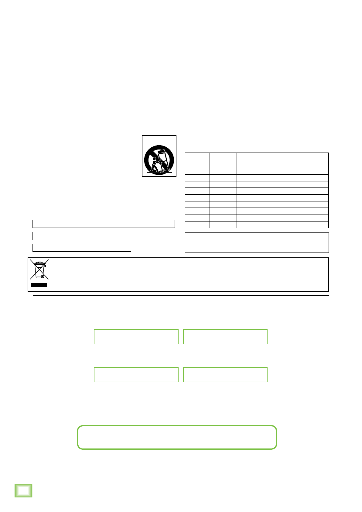
Two iP-12’s with a Mixer and Power Amplifier
Owner’s Manual
Left
Line level
Output
Right
Line level
Output
ProFX12 Mixer
Power Amplifier
CHANNEL 2 CHANNEL 1
BRIDGED
PIN
PIN
PIN
1+
1
CH 2
BRIDGED
1+
1+
1
2+
PIN
1+
2+
CH 1
1
2
The left and right line-level outputs from a mixer feed the inputs of a power amplifier. The speaker outputs
of the power amplifier feed the inputs of two iP-12 loudspeakers.
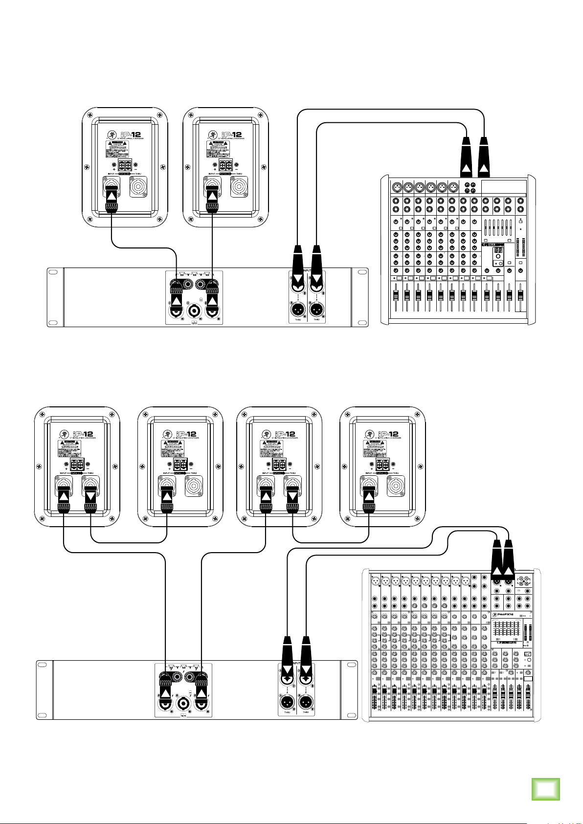
Four iP-12’s with a Mixer and Power Amplifier, Daisy-Chaining
BALANCED BALANCED
BAL/UNBAL BAL/UNBAL
L R
MAIN OUT
BAL/UNBAL BAL/UNBAL
L
L
(MONO)
R
R
AUX RETURN CR OUT SUB OUT
PROFESSIONAL MIC/LINE MIXER WITH FX
STEREO GRAPHIC EQ
15
10
5
0
5
10
15
MAIN MIX
EQ IN
MON 1
BYPASS
13 DELAY 1 (300ms)
01 BRIGHT ROOM
09 CHORUS
05 WARM HALL
14 DELAY 2 (380ms)
02 WARM LOUNGE
10 CHORUS + REV
06 CONCERT HALL
15 DELAY 3 (480ms)
03 SMALL STAGE
11 DOUBLER
07 PLATE REVERB
16 REVERB + DLY (250ms)
04 WARM THEATER
12 TAPE SLAP
08 CATHEDRAL
AUX
AUX
MASTER
RETURN
U
U
MON
TO
MON 1
1
+15
OO
+15
OO
OO
U
U
TO
MON
MON 2
2
+15
+15
OO
OO
OO
U
U
TO
MAIN
L-R
OO
+15
OO
+10
OO
U
TAPE
MAIN
USB
SUB 1-2
2-TRACK RETURN
USB OUT
+15
OO
LEVEL
RL RL RL RL
SUB 2 SUB 3SUB 1
dB
dB
dB
10
10
10
5
5
5
U
U
U
5
5
5
10
10
10
20
20
20
30
30
30
40
40
40
50
50
50
60
60
60
OO
OO
OO
Right
Line level
Output
IN OUT
PHONES
BAL/UNBAL BAL/UNBALBAL/UNBALBAL/UNBALBAL/UNBALBAL/UNBALBAL/UNBALBAL/UNBALBAL/UNBALBAL/UNBALBAL/UNBALBAL/UNBAL
PHANTOM POWER
48V
15
10
5
0
5
10
15
8K4K2K1K500250125
INTERNAL FX
U
TO
MON 1
+15
U
TO
MON 2
+15
U
TO
MAIN
L-R
+10
BREAK
(MUTES ALL CH)
SUB 4
dB
10
5
U
5
10
20
30
40
50
60
OO
Power Amplifier
CHANNEL 2 CHANNEL 1
BRIDGED
SPEAKER OUTPUTS
PIN
PIN
1+
1+
BRIDGED
2+
1
PIN
1+
2+
CH 1 CH 2
1
2
Left
Line level
7 8
OFF MAX
OFF MAX
COMP
COMP
U
U
G
G
A
A
C
C
I
I
N
N
I
I
M
M
U
U
+50
+50
+30dB
+30dB
-20dB
-20dB
GAIN
GAIN
LOW CUT
LOW CUT
EQ
EQ
U
U
HI
HI
12kHz
+15
+15
-15
-15
U
U
MID
MID
+15
+15
-15
-15
600
600
1.5k150
FREQ
FREQ
8k100
8k100
LOW
LOW
80Hz
80Hz
-15U+15
-15U+15
U
U
AUX
MON
1
1
+15
OO
+15
OO
U
U
MON
2
2
+15
OO
+15
OO
U
U
+15
OO
+15
OO
PAN
RL
RL
OL
OL OL OL OL OL
7
dB
dB
10
10
5
5
1-2
1-2
U
U
5
5
3-4
3-4
10
10
20
20
L-R
L-R
30
30
PFL
PFL
SOLO
SOLO
40
40
50
50
60
60
OO
OO
Output
BAL/UNBAL
1
BAL/UNBAL
2
MON SEND
11/129/10 13/14 15/16
BAL/UNBAL
L
L
L
(MONO)
(MONO)
(MONO)
LINE IN 9
LINE IN 11
LINE IN 13
R
R
R
LINE IN 10
LINE IN 12
LINE IN 14
G
G
U
A
A
C
C
I
I
N
N
I
I
M
M
U
U
+50
+50
+20-20
GAIN
GAIN
LOW CUT LOW CUT
EQ EQ EQ EQ EQ
U
HI
HI
HI
12kHz
12kHz
+15
-15U+15
-15
U
U
MID
MID
2.5kHz
2.5kHz
-15
-15
+15
+15
U
U
LOW
LOW
80Hz
80Hz
-15
-15
+15
+15
U
U
AUX
AUX
MON
MON
1
1
+15
OO
+15
OO
U
U
MON
MON
2
2
+15
OO
+15
OO
U
U
+15
OO
+15
OO
PAN
PAN
RL
RL
9/10 11/12 13/14 15/16
dB
dB
dB
10
10
10
5
5
5
1-2
1-2
U
U
U
5
5
5
3-4
3-4
10
10
10
20
20
20
L-R
L-R
30
30
30
PFL
PFL
SOLO
SOLO
40
40
40
50
50
50
60
60
60
OO
OO
HI
12kHz
-15U+15
U
MID
2.5kHz
-15
+15
U
LOW
80Hz
-15
+15
U
AUX
MON
1
+15
OO
U
MON
2
+15
OO
U
+15
OO
PAN
RL
1-2
3-4
L-R
PFL
SOLO
OO
12kHz
MID
1.5k150
FREQ
LOW
80Hz
AUX
MON
1
MON
2
PAN
866554433221
1-2
3-4
L-R
PFL
SOLO
FOOTSWITCH
BAL/UNBAL
FX SEND
BAL/UNBAL
L
(MONO)
LINE IN 15
R
LINE IN 16
U
+20-20
GAINGAIN
SOURCE
LINE
USB
HI
12kHz
-15U+15
U
MID
2.5kHz
-15
+15
U
LOW
80Hz
-15
+15
U
AUX
MON
1
+15
OO
U
MON
2
+15
OO
U
+15
OO
PAN
RL
dB
10
5
1-2
U
5
3-4
10
20
L-R
30
PFL
SOLO
40
50
60
OO
ProFX16 Mixer
MIC MIC MIC MIC MIC MIC MIC MIC MIC MIC
1
LINE IN LINE INLINE IN LINE IN LINE IN LINE IN
LINE IN
LINE IN
LINE IN
OFF MAX
INSERT
INSERT
U
U
G
G
A
A
C
C
I
I
N
N
I
I
M
M
U
U
+50
+50
+30dB
+30dB
-20dB
-20dB
-20dB
GAIN
GAIN
LOW CUT
LOW CUT
100Hz 100Hz 100Hz 100Hz 100Hz 100Hz 100Hz 100Hz 100Hz 100Hz
EQ
EQ
U
U
HI
HI
12kHz
12kHz
+15
+15
-15
-15
U
U
MID
MID
+15
+15
-15
-15
600
600
1.5k150
1.5k150
FREQ
FREQ
8k100
8k100
LOW
LOW
80Hz
80Hz
-15U+15
-15U+15
U
U
AUX
AUX
MON
MON
1
1
+15
OO
+15
OO
U
U
MON
MON
2
2
+15
OO
+15
OO
U
U
FXFXFX FX FX FX FX FX FX FX FX FX FX
+15
OO
+15
OO
PAN
PAN
RL
RL
OL
OL
MUTE MUTE MUTE MUTE MUTE MUTE MUTE MUTE MUTE MUTE MUTE MUTE
dB
dB
dB
10
10
10
5
5
PIN
1+
1
5
1-2
1-2
U
U
U
5
5
5
3-4
3-4
10
10
10
20
20
20
L-R
L-R
30
30
30
PFL
PFL
SOLO
SOLO
40
40
40
50
50
50
60
60
60
OO
OO
OO
OFF MAX
INSERT
INSERT
COMP
COMP
U
U
U
U
G
G
A
C
I
N
I
M
U
+50
+30dB
GAIN
LOW CUT
U
+15
-15
U
+15
-15
600
8k100
-15U+15
U
+15
OO
U
+15
OO
U
+15
OO
RL
OL
G
G
A
A
A
C
C
C
I
I
I
N
N
N
I
I
I
M
M
M
U
U
U
+50
+50
+50
+30dB
+30dB
+30dB
-20dB
-20dB
-20dB
GAIN
GAIN
GAIN
LOW CUT
LOW CUT
LOW CUT
EQ
EQ
EQ
U
U
U
HI
HI
HI
12kHz
12kHz
12kHz
12kHz
+15
+15
+15
-15
-15
-15
U
U
U
MID
MID
MID
+15
+15
+15
-15
-15
-15
600
600
600
1.5k150
1.5k150
1.5k150
1.5k150
FREQ
FREQ
FREQ
8k100
8k100
8k100
LOW
LOW
LOW
80Hz
80Hz
80Hz
-15U+15
-15U+15
-15U+15
U
U
U
AUX
AUX
AUX
MON
MON
PAN
AUX
MON
MON
MON
1
1
1
+15
OO
+15
OO
+15
OO
U
U
U
MON
MON
MON
2
2
2
+15
OO
+15
OO
+15
OO
U
U
U
+15
OO
+15
OO
+15
OO
PAN
PAN
PAN
RL
RL
RL
OL
OL
OL
dB
dB
dB
10
10
10
5
5
5
1-2
1-2
1-2
U
U
U
5
5
5
3-4
3-4
3-4
10
10
10
20
20
20
L-R
L-R
L-R
30
30
30
PFL
PFL
PFL
SOLO
SOLO
SOLO
40
40
40
50
50
50
60
60
60
OO
OO
OO
The left and right line-level outputs from a mixer feed the inputs of a power amplifier. The speaker outputs
of the power amplifier feed the inputs of two iP-12 loudspeakers. Their respective THRU jacks feed the
inputs of another pair of iP-12 loudspeakers.
Owner’s Manual
L
R
TAPE
123
LEVEL
SET
SIG/OL
INT FX
MUTE
4
MAIN
METERS
0dB = 0dBu
OL
15
10
6
3
0
2
4
7
10
20
30
RL
RUDE
SOLO
OO
MAX
CR/PHONES
MAIN
dB
dB
10
10
5
5
U
U
5
5
10
10
20
20
30
30
40
40
50
50
60
60
OO
OO
5
 Loading...