

Page 1
HR824 MK2
High Resolution Active Studio Monitor
O W N E R ’ S M ANUAL
Page 2
HR84 MK
HR824 MK2
IMPORTANT SAFETY INSTRUCTIONS
PORTABLE CART WARNING
Carts and stands - The
Component should be used
only with a cart or stand
that is recommended by
the manufacturer.
A Component and cart
combination should be
moved with care. Quick
stops, excessive force, and
uneven surfaces may cause
the Component and cart
combination to overturn.
CAUTION AVIS
RISK OF ELECTRIC SHOCK
DO NOT OPEN
RISQUE DE CHOC ELECTRIQUE
NE PAS OUVRIR
CAUTION: TO REDUCE THE RISK OF ELECTRIC SHOCK
DO NOT REMOVE COVER (OR BACK)
NO USER-SERVICEABLE PARTS INSIDE
REFER SERVICING TO QUALIFIED PERSONNEL
ATTENTION: POUR EVITER LES RISQUES DE CHOC
ELECTRIQUE, NE PAS ENLEVER LE COUVERCLE. AUCUN
ENTRETIEN DE PIECES INTERIEURES PAR L'USAGER. CONFIER
L'ENTRETIEN AU PERSONNEL QUALIFIE.
AVIS: POUR EVITER LES RISQUES D'INCENDIE OU
D'ELECTROCUTION, N'EXPOSEZ PAS CET ARTICLE
A LA PLUIE OU A L'HUMIDITE
The lightning flash with arrowhead symbol within an equilateral
triangle is intended to alert the user to the presence of uninsulated
"dangerous voltage" within the product's enclosure, that may be
of sufficient magnitude to constitute a risk of electric shock to persons.
Le symbole éclair avec point de flèche à l'intérieur d'un triangle
équilatéral est utilisé pour alerter l'utilisateur de la présence à
l'intérieur du coffret de "voltage dangereux" non isolé d'ampleur
suffisante pour constituer un risque d'éléctrocution.
The exclamation point within an equilateral triangle is intended to
alert the user of the presence of important operating and maintenance
(servicing) instructions in the literature accompanying the appliance.
Le point d'exclamation à l'intérieur d'un triangle équilatéral est
employé pour alerter les utilisateurs de la présence d'instructions
importantes pour le fonctionnement et l'entretien (service) dans le
livret d'instruction accompagnant l'appareil.
1. Read these instructions.
2. Keep these instructions.
3. Heed all warnings.
4. Follow all instructions.
5. Do not use this apparatus near water.
6. Clean only with dry cloth. Use a non-scratch cloth to protect the finish.
7. Do not block any ventilation openings. Install in accordance with the
manufacturer’s instructions.
8. Do not install near any heat sources such as radiators, heat registers,
stoves, or other apparatus (including amplifiers) that produce heat.
9. Do not defeat the safety purpose of the polarized or grounding-type
plug. A polarized plug has two blades with one wider than the other.
A grounding-type plug has two blades and a third grounding prong.
The wide blade or the third prong are provided for your safety. If the
provided plug does not fit into your outlet, consult an electrician for
replacement of the obsolete outlet.
10.
Protect the power cord from being walked on or pinched particularly at
plugs, convenience receptacles, and the point where they exit from the
apparatus.
11.
Only use attachments/accessories specified by the manufacturer.
12.
Use only with a cart, stand, tripod, bracket, or table specified by the
manufacturer, or sold with the apparatus. When a cart is used, use
caution when moving the cart/apparatus combination to avoid injury
from tip-over.
13.
Unplug this apparatus during lightning storms or when unused for long
periods of time.
14.
Refer all servicing to qualified service personnel. Servicing is required
when the apparatus has been damaged in any way, such as powersupply cord or plug is damaged, liquid has been spilled or objects have
fallen into the apparatus, the apparatus has been exposed to rain or
moisture, does not operate normally, or has been dropped.
15.
This apparatus shall not be exposed to dripping or splashing, and no
object filled with liquids, such as vases, shall be placed on the apparatus.
16.
This apparatus has been designed with Class-I construction and must
be connected to a mains socket outlet with a protective earthing con
-
nection (the third grounding prong).
17.
Note that this apparatus is not completely disconnected from the AC
mains service when the power switch is in the OFF position.
18. This apparatus does not exceed the Class A/Class B (whichever is
applicable)
set out in the radio interference regulations of the Canadian Department
limits for radio noise emissions from digital apparatus as
of Communications.
ATTENTION — Le présent appareil numérique n’émet pas de bruits
radioélectriques dépassant las limites applicables aux appareils numériques de
class A/de class B (selon le cas) prescrites dans le réglement sur le brouillage
radioélectrique édicté par les ministere des communications du Canada.
19.
Exposure to extremely high noise levels may cause permanent hearing
loss. Individuals vary considerably in susceptibility to noise-induced
hearing loss, but nearly everyone will lose some hearing if exposed to
sufficiently intense noise for a period of time. The U.S. Government’s
Occupational Safety and Health Administration (OSHA) has specified
the permissible noise level exposures shown in the following chart.
According to OSHA, any exposure in excess of these permissible limits
could result in some hearing loss. To ensure against potentially danger
ous exposure to high sound pressure levels, it is recommended that all
persons exposed to equipment capable of producing high sound pres
sure levels use hearing protectors while the equipment is in operation.
Ear plugs or protectors in the ear canals or over the ears must be worn
when operating the equipment in order to prevent permanent hearing
loss if exposure is in excess of the limits set forth here.
Duration Per Day Sound Level dBA, Typical
In Hours Slow Response Example
8 90 Duoinsmallclub
6 92
4 95 SubwayTrain
3 97
2 100 Veryloudclassicalmusic
1.5 102
1 105 Hometheater(loudestpeaks)
0.5 110
0.25orless 115 Loudestpartsatarockconcert
WARNING — To reduce the risk of fire or
electric shock, do not expose this apparatus
to rain or moisture.
-
-
Page 3

INTRODUCTION
Tweeter
Woofer
Passive Radiator
Power Amplifier/
Crossover Assembly
Owner’s Manual
Thank you for choosing the Mackie HR824 MK2 Studio
Monitors. We began producing the original HR824
Studio Monitors in 1997, and they quickly became the
standard by which near-field studio reference monitors
were compared for extremely flat frequency response at
a reasonable price. The HR824 MK2s have been redesigned with modern components for improved accuracy
and an extended low-frequency response.
Investments in Excellence...
When we decided it was time to update the HR824s,
we turned to our expert loudspeaker and transducer design engineering team at EAW to determine how to make
an already excellent studio monitor even better. The
first thing they noticed was that the front baffle could
be redesigned with a rounder aluminum construction
to further reduce edge diffraction for improved imaging. The volume of the cabinet was increased slightly to
improve the low-frequency response. The amplifiers have
been adjusted with all new ‘voicing’ to match the new
cabinets. However, the amplifiers’ design is fundamentally the same and has a very similar characteristic to the
original model. If you are upgrading from the original
HR824s, you won’t have to relearn the sound. The MK2s
still deliver the clarity, ultra-linear frequency response,
and broad stereo imaging of the originals.
An elegant piano-black gloss finish emphasizes that
these studio monitors are in a class by themselves,
pleasing to the most discerning eye as well as the most
discerning ear.
The result? The HR824 MK2 Studio Monitors are
extremely accurate and versatile, loaded with unique controls that allow you to fine-tune the sound to match your
individual environment precisely. You’re gonna love these!
What are they? The Advantages...
• The amplifiers are designed to provide maximum
acoustic output from the speakers, yet minimize
the danger of speaker damage due to overdriving.
• In addition, the amplifiers’ gain and frequency re
sponses are individually hand-trimmed to compensate for typical manufacturing tolerances between
the drivers and produce a smooth frequency
response from 35 Hz to 20 kHz.
• The connecting wires between the amplifier outputs
and the drivers are kept to an absolute minimum,
so the damping factor of the amplifier isn’t compromised by the resistance of long speaker cables.
• The acoustic sum of the outputs from the two driv
ers are optimized electronically, as well as physically, so the amplitude response is unity and the
phase difference is minimal.
In short, all the complex interconnected components
in the system are designed to work in harmony with
each other to produce the best possible sound.
The Transducers...
The monitors feature an 8.75-inch high-precision, lowdistortion
dome tweeter on the front, and a 6-inch x 12-inch elliptical flat piston passive radiator in the back.
The high-frequency driver is mounted on a massive,
acoustically non-resonant die-cast aluminum exponential
waveguide, which results in wide, controlled dispersion
of high-frequency sounds. The unique passive radiator
design provides tight, articulate bass response down to
35 Hz — an astounding accomplishment for a cabinet
of this size! And since the radiator is producing most of
the sound at the lowest frequencies, there is very little
distortion from the woofer because its cone movement
is minimal at those frequencies.
woofer and a 1-inch ferrofluid cooled titanium
-
-
The HR824 MK2 Studio Monitors are highresolution
tors employing a 6th-order Butterworth system
with a built-in rear-firing mass-loaded passive
radiator. Whew! There are many benefits to
integrating an active crossover, power amplifiers, and drivers into a single cabinet, and we’ve
taken full advantage of these benefits in the
design of the HR824 MK2.
• The crossover point is designed so that the
, two-way, bi-amplified, active moni-
high- and low-frequency drivers are fed
only the frequencies they are best able to
reproduce.
Figure 1. HR824 MK2 Cutaway side view
Owner’s Manual
Page 4
4
HR84 MK
HR824 MK2
The Cabinet...
The cabinet is made of MDF with a high-gloss pianoblack finish. Internal bracing increases the strength and
rigidity (stiffness) of the box. An open-cell adiabatic
foam material fills the inside of the box to absorb internal reflections and dampen standing waves. Mounting
hardware is installed on the bottom of the cabinet that
fits the 60.0 WB OmniMount wall-mount bracket (see
“Placement” on page 6 for more info).
FR Series Power Ampliers...
What better way to power the loudspeakers than with
our acclaimed FR Series “Fast Recovery” power amplifiers. Our Fast Recovery design uses low negative feedback, yet allows the amplifiers to maintain low distortion and stability even when driven into clipping.
The low-frequency amplifier produces up to 150 watts
continuous (350 watts peak) before clipping, while
the high-frequency amplifier produces up to 100 watts
continuous (210 watts peak).
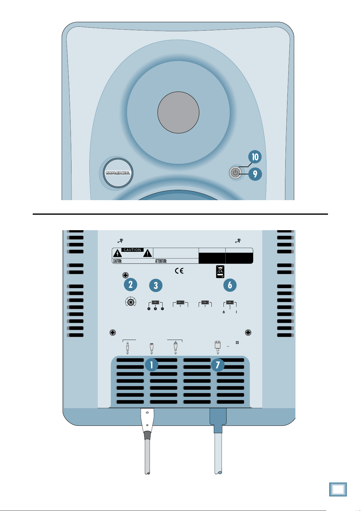
1. Connect the line-level monitor signal from your mixer,
preamp, or other signal source to the SIGNAL INPUT
[1] jack on the HR824 MK2 Studio Monitor (1⁄4-inch
PHONE, XLR, or RCA).
2. Connect the supplied AC power cord to the IEC socket
[7] on the back of the monitor. Plug the other end into
an AC outlet properly configured with the correct voltage for your particular model.
3. Set the POWER MODE [6] switch on the rear panel to
the ON position. With the front panel power switch [9]
out, the power amplifier is in Standby mode.
4. Start your signal source (tape deck, CD, DAW, or
whatever), but leave the master volume control on your
mixer or preamp down.
5. Push in the power switch [9] on the front of the HR824
MK2. The power ring [10] around the switch will illuminate.
6. Slowly turn up the INPUT SENSITIVITY [2] control on
the back of the monitor to its fully clockwise position
(NORMAL).
7. Adjust the master volume on your mixer to a comfort
ably loud listening level. Enjoy the silky smooth highs
and authoritative, commanding lows of the HR824 MK2.
Then read the rest of this manual.
-
QUICK START
We realize that you can’t wait to hook
up your new Mackie HR824 MK2 High
Resolution Studio Monitors and try
them out. Nevertheless, please take
the time to read this page NOW, and
the rest can wait until you’re good and ready.
Each of the HR824 MK2 cabinets has its own builtin power amplifiers. That’s right, two amplifiers per
speaker cabinet; one for the high-frequency tweeter
and one for the low-frequency woofer. You should turn
the INPUT SENSITIVITY [2] control on the back of the
cabinet down (fully counterclockwise) before turning
on the Studio Monitors for the first time. Also be sure
to set the power switch [9] on the front panel to its
standby position (out). This will prevent you from accidentally connecting a hot signal source to the monitors
and getting a rude surprise.
There are a number of other settings you can make
on the back of the HR824 MK2, and you can look at the
graphic instructions relating to each of them on the
back of the cabinet (or wait until you read about them
later on in this manual so you really know what they
do). For now, just leave them at the factory default
settings (ACOUSTIC SPACE = WHOLE; LOW FREQ =
49Hz; HIGH FREQ = 0), except for the POWER MODE
[6] switch. Be sure it is set to the STANDBY position.
AN EXTREMELY IMPORTANT NOTE
ON HR824 MK2 BASS RESPONSE
AND YOUR CONTROL ROOM.
Your new HR824 MK2s achieve their
best bass response in a room that’s
optimized for bass reproduction. A
lot of factors can conspire to thwart
the HR824 MK2s’ extended low
frequency — including room shape, room volume and
acoustical treatment.
This is not a cop-out or an apology. It’s plain old
physics in action. Luckily we’ve armed you with some
compensating controls that you can use to optimize the
frequency response of the speakers in your particular
room. Consider the following:
The ACOUSTIC SPACE switch
must be set correctly.
When you put your HR824 MK2s in a corner or up
against walls, their bass characteristics change. Adjust
the ACOUSTIC SPACE [3] switch setting accordingly to
avoid muddy or exaggerated low frequency response.
Page 5
AUTO
STANDBY
ON
MAINS INPUT
120VAC
60 Hz 150W
SIGNAL INPUTS BAL/UNBAL
ACOUSTIC SPACE
0
dB
–
2dB
–
3dB
–
4
dB
20 100Hz
LOW FREQ
LOW CUT
24dB/oct
LOW CUT
BUTTERWORTH
47Hz
80Hz
HIGH FREQ
0dB
–
2dB
10kHz
+
2dB
ACOUSTIC SPACE APPLICATIONS
C
SPEAKERS AGAINST WALLSPEAKERS IN CORNERS
B
CONSOLE
CONSOLE
A
HALF SPACE
QUARTER SPACE
37Hz
SPEAKERS AWAY FROM WALLS
CONSOLE
WHOLE SPACE
XLRPHONE
0dB
RCA
ON
ACOUSTIC SPACE LOW FREQ HIGH FREQ. POWER MODE
NORMALOFF
HALFQUARTER
WHOLE
(
NORMAL
)
37Hz80Hz
0
(
NORMAL
)
–
2dB+2dB
47Hz
INPUT
SENSITIVITY
LOW CUT
–
10dB
(
NORMAL
)
INTERNAL BI •AMPLIFICATION
150W. L. F. / 100W . H.F.
™
PATENT NO:
DES. 387,351
"THX PM3" AND "LUCASFILM" ARE TRADEMARKS OF LUCASFILM, LTD. USED BY PERMISSION
DESIGNED BY MACKOIDS IN WOODINVILLE, WA, USA • MANUFACTURED IN CHINA • FABRIQUE EN CHINE • COPYRIGHT ©2005
"MACKIE", "FR SERIES" AND THE RUNNING MAN FIGURE ARE TRADEMARKS OF LOUD TECHNOLOGIES, INC. • PATENT PENDING
SERIAL NUMBER
MANUFACTURING DATE
RISK OF ELECTRIC SHOCK
DO NOT OPEN
REPLACE WITH THE SAME TYPE FUSE AND RATING.
DISCONNECT SUPPLY CORD BEFORE CHANGING FUSE
UTILISE UN FUSIBLE DE RECHANGE DE MÊME TYPE.
DEBRANCHER AVANT DE REMPLACER LE FUSIBLE
WARNING:
TO REDUCE THE RISK OF FIRE OR ELECTRIC SHOCK, DO NOT
EXPOSE THIS EQUIPMENT TO RAIN OR MOISTURE. DO NOT REMOVE COVER.
NO USER SERVICEABLE PARTS INSIDE. REFER SERVICING TO QUALIFIED PERSONNEL.
AVIS:
RISQUE DE CHOC ELECTRIQUE — NE PAS OUVRIR
This device complies with part 15 of the FCC Rules.
Operation is subject to the following two conditions:
(1) This device may not cause harmful interference, and
(2) This device must accept any interference received,
including interference that may cause undesired operation.
ROHS
Owner’s Manual
Owner’s Manual
Page 6
HR84 MK
HR824 MK2
Feel free to experiment.
Placement
In many respects, every room is unique in terms of its
acoustics.
Even after you’ve read about how to set the HR824
MK2’s rear panel switches, try other settings to see if
your particular room environment requires different
adjustments.
And, even after you’ve placed your monitors where you
think they’ll sound best, try moving them around. You
might be pleasantly surprised.
Finally, keep an open mind about
improving your room’s acoustics
and bass-handling ability.
Nobody likes to buy a new set of monitor speakers
and then be told that they should spend extra bucks on
bass traps or a remodeling job. But the simple fact is,
“standard” rooms, i.e., rectangular rooms in conventional business or residential structures, are rarely if ever
conducive to optimal low bass reproduction without
some modifications.
Luckily, there are plenty of options short of building
a new control room, many of which are covered in this
manual.
Additional Tidbits of Wisdom
• When you shut down your equipment, turn off the
HR824 MK2 studio monitors first to prevent thumps
and other noises generated by any upstream equipment
from coming out the speakers. When powering up, turn
on the monitors last.
• Save the shipping box! You may need it someday, and
you don’t want to have to pay for another one.
• Save your sales receipt in a safe place.
• Also record all HR824 MK2 serial numbers in the space
provided on the next page, along with where and when
you bought them.
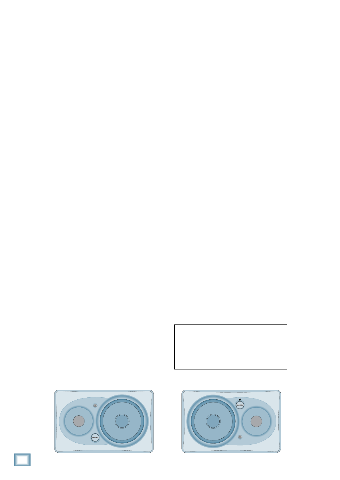
The HR824 MK2s were designed to be placed in a
vertical position. If you find it necessary to place the
speakers in a horizontal position (on their sides), place
them so that the woofers are toward the inside; that is,
so the woofers are closest to each other. This provides
the best low-frequency summing and overall imaging.
The HR824 MK2s can also be wall-mounted using the
mounting hardware located on the bottom of the cabinet. This is designed to be used with the OmniMount
60.0 WB (Wall-to-Bottom) wall-mount bracket, which
provides a wide range of horizontal and vertical movement to meet your coverage requirements. Refer to the
OmniMount website for more details.
www.omnimount.com/pro/product.aspx?ProductId=1ec10a27b84e-4ec8-9155-db5b646335bd&CurrentId=1.1.1.1
A Few Words About THX™ pm™
Certication
Nearly two decades ago, George Lucas turned a
passion for great sound into the world’s most accepted
and trusted solution for achieving it. The standard was
named THX (for Tomlinson Holman, who developed
the THX Sound System when he was the research and
technical director at Lucasfilm Ltd.™ in the early 80s),
and today, with hundreds of thousands of home theater
customers and more than 3000 THX Certified movie theaters enjoying its benefits, the THX name has become
nothing short of legendary. Simply put: when it comes
to premium sound, no other name so closely defines
‘quality’ for millions of movie-goers and home theater
enthusiasts alike.
Today, a new landscape is emerging. A landscape comprised of hundreds of small, professional multi-channel
facilities, whose need for differentiation, expert technical and marketing support, and a true, multi-channel
Note: The Mackie logo can be rotated 90º so
that it is oriented correctly when placing the
speakers on their sides. Gently pull out on
the Mackie emblem, rotate it, and push it
back into place.
Page 7

standard is becoming a competitive fact of life. Again,
THX has a singular solution and this time it’s called
THX pm3 Certification.
Owner’s Manual
Contents
All facilities involved with mixing and/or monitoring
of multi-channel material should have the option to use
pm3. THX pm3 Certification is ideal for DVD mastering,
sweetening, and mixing; and is also perfect for facilities
doing work in broadcast, music, or multi-media applications.
HR84 MK THX pm Certication
When we submitted the HR824 MK2s for THX pm3
Certification, they passed on the first try with no modifications!
Anyone seeking THX Certification for their studio,
or striving to maintain THX standards, can use the
HR824 MK2s and rest assured that their facility is in
full compliance.
IMPORTANT SAFETY INSTRUCTIONS ...........
INTRODUCTION..................................................
QUICK START ...........................................................................4
REAR PANEL DESCRIPTION ..............................8
1. SIGNAL INPUTS................................................................8
. INPUT SENSITIVITY ........................................................8
. ACOUSTIC SPACE.............................................................8
4. LOW FREQ FILTER ...........................................................9
. HIGH FREQ FILTER ..........................................................9
. POWER MODE................................................................10
. Mains Input .....................................................................10
8. Passive Radiator .............................................................11
FRONT PANEL DESCRIPTION ..........................1
9. Power Switch ..................................................................1
10. Power Ring and Overload Indicator ......................1
PROTECTION CIRCUITS ....................................1
Overload Protect ..............................................................1
Thermal Protect .................................................................1
Integrated Magnetic Shielding ......................................1
Input Signal Wiring ...........................................................1
CARE AND CLEANING .......................................1
SERVICE INFO ......................................................14
Troubleshooting.................................................................14
Repair ....................................................................................1
TECHNICAL INFORMATION ...........................1
HR84 MK Specications .................................................1
Graphs ...................................................................................1
HR84 MK Block Diagram .............................................18
• Please write the serial number for your studio monitor here
(all studio monitors if you have more than one) for future reference
(i.e., insurance claims, tech support, return authorization, etc.):
Monitor 1 Monitor 2
Purchased at:___________________________________ Date of Purchase:_____________
Monitor 3
Part No. 0022104 Rev. B1 11/07
©2007 LOUD Technologies Inc. All Rights Reserved.
Owner’s Manual
Page 8

8
HR84 MK
HR824 MK2
REAR PANEL DESCRIPTION
AUTO
STANDBY
ON
ON
ACOUSTIC SPACE LOW FREQ HIGH FREQ. POWER MODE
NORMALOFF
HALFQUARTER
WHOLE
(
NORMAL
)
37Hz80Hz
0
(
NORMAL
)
–
2dB
+
2dB
47Hz
INPUT
SENSITIVITY
LOW CUT
–
10dB
(
NORMAL
)
AUTO
STANDBY
ON
ON
ACOUSTIC SPACE LOW FREQ HIGH FREQ. POWER MODE
HALFQUARTER
WHOLE
(
NORMAL
)
37Hz80Hz
0
(
NORMAL
)
–
2dB
+
2dB
47Hz
LOW CUT
(
NORMAL
)
This is where you connect your signal to the monitor,
and make adjustments to the frequency response of
the speakers to match the monitor’s location and your
room’s environment.
For THX applications, the rear panel
switches and controls should be set
to the THX positions as indicated in
this section.
1. SIGNAL INPUTS
The location of the signal input jacks makes the connectors exit down and not straight out the back of the
enclosure. This flush-mount design allows you to place
the monitor right up against the wall if desired.
• The XLR female, TRS female (balanced), and RCA
female (unbalanced) input connectors are provided for
user convenience.
• Don’t connect more than one source to the jacks.
• Unbalanced TS (tip-sleeve) lines can be accommodated
via the TRS jack. Make sure the cable terminates with
a TS plug (like a guitar plug), or if it’s a TRS plug (such
as a headphone plug), make sure the ring is tied to the
sleeve and that the plug is fully inserted into the jack.
• The XLR and TRS input connectors accept balanced or
unbalanced signals. The connectors are wired as follows
(per the AES/IEC standard):
XLR TRS RCA
. INPUT SENSITIVITY
THX = NORMAL
The HR824 MK2 expects a line-level signal at its input
connectors.
• The reference sensitivity is –7.5 dBu=100 dB SPL at
one meter (39 inches) with the INPUT SENSITIVITY
control set to its NORMAL position (in other words,
wide open).
• The HR824 MK2 is designed to operate with a +4 dBu
signal when the INPUT SENSITIVITY control is in the
NORMAL position.
• Refer to the QUICK START section on page 4 for the
level-setting procedure.
. ACOUSTIC SPACE
Hot (+) Pin 2 Tip Tip
Cold (–) Pin 3 Ring —
Shield (Ground) Pin 1 Shield Shield
• The HR824 MK2s can be used with a home receiver
even if the receiver lacks a preamp output by using a
speaker-level to line-level signal attenuator. (See page
13 for more information.)
THX = WHOLE (NORMAL)
This is a three-way switch that adjusts the low-frequency response of the monitors to compensate for their
placement in the room. See page 5 for an overview of
the rear panel.
• If you place the HR824 MK2 monitors against a wall
(half space [3B]), set the ACOUSTIC SPACE switch
to the “B” position. This activates a shelving filter to
reduce the low-frequency output by 2 dB to compensate
for the half-space placement.
• If you place the monitors into the corners of your
room (quarter space [3A]), the low-frequency output
approximately doubles from what it is in half space.
Set the ACOUSTIC SPACE switch to the “A” position to
reduce the low-frequency output by 4 dB to compensate
for the quarter-space placement.
• If you use the HR824 MK2s free-standing, away from
walls and corners (whole space [3C]), set the ACOUSTIC SPACE switch to the “C” position (NORMAL).
Page 9

AUTO
STANDBY
ON
MAINS INPUT
120VAC
60 Hz 150W
SIGNAL INPUTS BAL/UNBAL
ACOUSTIC SPACE
0dB
–
2dB
–
3dB
–
4
dB
20 100Hz
LOW FREQ
LOW CUT
24dB/oct
LOW CUT
BUTTERWORTH
47Hz
80Hz
HIGH FREQ
0dB
–
2dB
10kHz
+
2dB
ACOUSTIC SPACE APPLICATIONS
C
SPEAKERS AGAINST WALLSPEAKERS IN CORNERS
B
CONSOLE
CONSOLE
A
HALF SPACE
QUARTER SPACE
37Hz
SPEAKERS AWAY FROM WALLS
CONSOLE
WHOLE SPACE
XLRPHONE
0
dB
RCA
ON
ACOUSTIC SPACE LOW FREQ HIGH FREQ. POWER MODE
NORMALOFF
HALFQUARTER
WHOLE
(
NORMAL
)
37Hz80Hz
0
(
NORMAL
)
–
2dB
+
2dB
47Hz
INPUT
SENSITIVITY
LOW CUT
–
10dB
(
NORMAL
)
PATENT NO:
DES. 387,351
DESIGNED BY MACKOIDS IN WOODINVILLE, WA, USA • MANUFACTURED IN CHINA • FABRIQUE EN CHINE • COPYRIGHT ©2007
"MACKIE", "FR SERIES" AND THE RUNNING MAN FIGURE ARE TRADEMARKS OF LOUD TECHNOLOGIES, INC. • PATENT PENDING
SERIAL NUMBER
MANUFACTURING DATE
RISK OF ELECTRIC SHOCK
DO NOT OPEN
REPLACE WITH THE SAME TYPE FUSE AND RATING.
DISCONNECT SUPPLY CORD BEFORE CHANGING FUSE
UTILISE UN FUSIBLE DE RECHANGE DE MÊME TYPE.
DEBRANCHER AVANT DE REMPLACER LE FUSIBLE
WARNING:
TO REDUCE THE RISK OF FIRE OR ELECTRIC SHOCK, DO NOT
EXPOSE THIS EQUIPMENT TO RAIN OR MOISTURE. DO NOT REMOVE COVER.
NO USER SERVICEABLE PARTS INSIDE. REFER SERVICING TO QUALIFIED PERSONNEL.
AVIS:
RISQUE DE CHOC ELECTRIQUE — NE PAS OUVRIR
This device complies with part 15 of the FCC Rules.
Operation is subject to the following two conditions:
(1) This device may not cause harmful interference, and
(2) This device must accept any interference received,
including interference that may cause undesired operation.
INTERNAL BI•AMPLIFICAT ION
150W. L.F. / 10 0W. H.F.
™
THE THX LOGO AND PM3 ARE TRADEMARKS OF THX LTD. WHICH MAY BE REGISTERED IN SOME JURISDICTIONS.
ALL RIGHTS REVERVED
ROHS
AUTO
STANDBY
ON
ON
0
(
NORMAL
)
–
2dB
+
2dB
4. LOW FREQ FILTER
AUTO
STANDBY
ON
ON
37Hz80Hz
0
(
NORMAL
)
–
2dB
+
2dB
47Hz
LOW CUT
(
NORMAL
)
Removing the low-frequency content also allows
Owner’s Manual
you to raise the overall output level somewhat. Lowfrequency information requires the largest amount of
an amplifier’s output, so restricting the low-frequency
content allows raising the mid-frequency level somewhat. If your client insists on mixing LOUD, this may be
a workable strategy.
THX = 80Hz
The LOW FREQ FILTER switch inserts a low-frequency
rolloff into the response curve.
• For some applications, the low-frequency output of the
HR824 MK2 may impair your ability to make mix judgements.
• For THX applications, use the 80Hz setting.
• For non-THX applications where a sub-woofer isn’t en
hancing low-frequency output use the 37Hz (NORMAL)
position.
• The LOW FREQ switch affects the low-frequency con
tent of your mix. Remember how things work in reverse,
so removing the deep bass content on playback may
actually increase it in the final mix.
• You can use the LOW FREQ switch’s 80Hz position to
simulate a smaller loudspeaker, especially one with
limited low-frequency capability (like a certain popular
2-way nearfield monitor). You may need to do this if a
small speaker is the eventual destination of your mix,
or perhaps just to see how your mix sounds on a clock
radio.
. HIGH FREQ FILTER
The HIGH FREQ FILTER switch tailors the overall
high-frequency response by ±2 dB beginning at 10kHz.
Leave this switch in the 0 (NORMAL) position unless:
• You want to subtly brighten or darken the sound of the
speakers.
• Perhaps you have hearing loss caused by too many
nights in front of a double Marshall stack.
• You just like to mix on the bright side or dull side.
If your mixes consistently sound dull or dark when
you listen elsewhere, this usually indicates that your
monitors are too bright, relative to your normal hearing.
A bit less high-frequency energy usually fixes this, and
you can force the mix in this direction by reducing the
high-frequency output of the monitors by using the –2 dB
position of the switch.
THX = 0 dB
Owner’s Manual
9
Page 10

10
HR84 MK
HR824 MK2
AUTO
STANDBY
ON
MAINS INPUT
120VAC
60 Hz 150W
SIGNAL INPUTS BAL/UNBAL
ACOUSTIC SPACE
0dB
–
2dB
–
3dB
–
4
dB
20 100Hz
LOW FREQ
LOW CUT
24dB/oct
LOW CUT
BUTTERWORTH
47Hz
80Hz
HIGH FREQ
0dB
–
2dB
10kHz
+
2dB
ACOUSTIC SPACE APPLICATIONS
C
SPEAKERS AGAINST WALLSPEAKERS IN CORNERS
B
CONSOLE
CONSOLE
A
HALF SPACE
QUARTER SPACE
37Hz
SPEAKERS AWAY FROM WALLS
CONSOLE
WHOLE SPACE
XLRPHONE
0dB
RCA
ON
ACOUSTIC SPACE LOW FREQ HIGH FREQ. POWER MODE
NORMALOFF
HALFQUARTER
WHOLE
(
NORMAL
)
37Hz80Hz
0
(
NORMAL
)
–
2dB+2dB
47Hz
INPUT
SENSITIVITY
LOW CUT
–
10dB
(
NORMAL
)
PATENT NO:
DES. 387,351
DESIGNED BY MACKOIDS IN WOODINVILLE, WA, USA • MANUFACTURED IN CHINA • FABRIQUE EN CHINE • COPYRIGHT ©2007
"MACKIE", "FR SERIES" AND THE RUNNING MAN FIGURE ARE TRADEMARKS OF LOUD TECHNOLOGIES, INC. • PATENT PENDING
SERIAL NUMBER
MANUFACTURING DATE
RISK OF ELECTRIC SHOCK
DO NOT OPEN
REPLACE WITH THE SAME TYPE FUSE AND RATING.
DISCONNECT SUPPLY CORD BEFORE CHANGING FUSE
UTILISE UN FUSIBLE DE RECHANGE DE MÊME TYPE.
DEBRANCHER AVANT DE REMPLACER LE FUSIBLE
WARNING:
TO REDUCE THE RISK OF FIRE OR ELECTRIC SHOCK, DO NOT
EXPOSE THIS EQUIPMENT TO RAIN OR MOISTURE. DO NOT REMOVE COVER.
NO USER SERVICEABLE PARTS INSIDE. REFER SERVICING TO QUALIFIED PERSONNEL.
AVIS:
RISQUE DE CHOC ELECTRIQUE — NE PAS OUVRIR
This device complies with part 15 of the FCC Rules.
Operation is subject to the following two conditions:
(1) This device may not cause harmful interference, and
(2) This device must accept any interference received,
including interference that may cause undesired operation.
INTERNAL BI•AMPLIF ICATION
150W. L.F. / 100W. H.F .
™
THE THX LOGO AND PM3 ARE TRADEMARKS OF THX LTD. WHICH MAY BE REGISTERED IN SOME JURISDICTIONS.
ALL RIGHTS REVERVED
ROHS
Conversely, if your mixes are consistently too bright,
AUTO
STANDBY
ON
ON
then adding some additional high-frequency energy in
the monitors satisfies your ears, and the resultant mix
has less HF content.
The timbre of your monitors affects
the way that your mixes play on other
equipment. Remember that the monitors have a mirroring effect on the
mix; if the monitors make something
too loud in the mix it usually results in not enough of
that thing on tape.
Start with the response modification switches in the
factory recommended settings (see Quick Start Section). After prolonged listening, if you notice a trend in
your mixes, perhaps making some small adjustments as
suggested here will help.
It’s a real rush to mix really loud. But remember that
the resulting mix only sounds good when you play it at
least that loud. However strange it may sound, mixes
made at lower levels sound even better when played
loud; perhaps even a bit bigger than life.
Get that sound level meter out. Decide what level
you’re going to mix at and use the meter to help keep
your mixing at that level. Your ears will thank you, and
your mixes will be better for it.
. POWER MODE
This 3-position switch turns the amplifiers on or off, or
sets them to automatic mode. Use this switch to set the
HR824 MK2s to your preferred mode of operation, and
use the front panel power
• In the STANDBY position, the power amplifiers are in
Standby mode and produce no sound. Low-level circuitry
is still active, but the power consumption of the circuitry is minimal (8 watts).
• Flip the switch to the ON position and the power ampli
fiers are live and operate normally. (The front panel
power [9] switch must also be IN.)
• When it’s in the AUTO ON position, the amplifiers turn
on and off depending on the presence or absence of an
input signal. An input signal level of –45 dBu (minimum) activates the auto-on function. A silent period
greater than eight minutes activates the auto-off function. The power ring [10] on the front panel reflects the
state of the amplifiers.
switch for convenience.
[9]
-
. Mains Input
Connect the power cord to this IEC socket, and plug
the other end into your AC outlet.
Page 11

• When the POWER MODE [6] switch is in the ON
Tweeter
Woofer
Passive Radiator
position (and the front panel power switch [9] is in the
IN position), applying AC power activates the muting
circuit for about four seconds while the power supply
and internal circuitry stabilize, then the HR824 MK2
unmutes and is ready to go.
8. Passive Radiator
When you mount a loudspeaker in a box, there are two
things that you can do with the radiation from the rear of
the cone: use it to enhance the low-frequency performance
of the speaker system (bass reflex system) or soak it up
(acoustic suspension system).
• A bass reflex system uses the rear radiation to extend
the low-frequency response. Most systems provide holes
(ports) in the front or back of the cabinet to release the
rear wave. Sometimes the holes have tubes (ducts) in
them. The dimensions of the holes and the volume of
the cabinet work with the characteristics of the woofer
to produce low-frequency extension. These systems are
characterized by good low-frequency performance down
to the –3 dB frequency set by the design. Below this
frequency, the frequency response falls at 24 dB/octave
or more.
The HR824 MK2 is a bass reflex 6th-order system.
Rather than use ports, the vent takes the form of a passive radiator, a mass-loaded flat piston coupled to the air
trapped within the enclosure. You can’t see the passive
radiator because it is located at the rear of the cabinet,
behind the power amplifier assembly.
• Simple ports or ducts must have sufficient surface
area to prevent the velocity of the air within them from
exceeding 5% of the speed of sound, which keeps the
vent from becoming audible (breathing and wheezing
sounds) at high signal levels.
• This requirement for sufficient surface area creates a
design problem when using ports — finding enough
space in the enclosure for them to fit.
The passive radiator replaces the port found on most
speaker systems. It offers several advantages to simple
porting:
• One primary advantage of a passive radiator is that it
can reproduce low frequencies with lower distortion
and at a higher sound pressure level (SPL) than a
simple port or duct.
• Our unique passive radiator design uses a flat dia
phragm providing exceptional stiffness to the radiating
surface.
• The elliptical shape of the passive radiator takes up
nearly the entire surface area available on the rear of
the enclosure, allowing the passive radiator to move
more air than a port.
Owner’s Manual
-
Owner’s Manual
11
Page 12

1
HR84 MK
HR824 MK2
FRONT PANEL DESCRIPTION
AUTO
STANDBY
ON
ON
9. Power Switch
Use this switch to turn on or off the HR824 MK2 from
the front. It works with the POWER MODE [6] switch
on the rear panel in the following way:
• If the POWER MODE switch on the rear panel is set
to STANDBY, the front panel power [9] switch has no
effect. The power [10] ring remains off.
• If the POWER MODE switch is ON, the front panel
power switch turns the HR824 MK2 on or returns it to
STANDBY mode, as indicated by the power ring.
• If the POWER MODE switch is in the AUTO ON posi
tion, the front panel power switch turns the HR824 MK2
on, even when there is no signal present. If there is no
signal after about two minutes, the auto-off function
is activated and the amplifiers go into Standby mode,
indicated when the power ring goes off.
10. Power Ring and Overload Indicator
-
The power ring around the power switch illuminates
when the power amplifiers are on, and turns off when
the amplifiers are in Standby mode or off.
The power ring turns red when the overload protection circuit has been triggered.
• Occasional blinking of the overload indicator means
that the loudest transients are reaching the maximum
drive capability of the amplifiers. This is okay, although
distortion may be audible.
• Frequent or continuous blinking of the overload indica
tor means that you have exceeded the maximum drive
allowed for the speakers. The amplifiers are clipping,
and the overload protection circuit has taken over, reducing the input level. You should reduce the level from
your signal source until the overload indicator blinks
occasionally or not at all.
-
PROTECTION CIRCUITS
There are a number of protection mechanisms designed into the HR824 MK2 to safeguard the loudspeakers from inadvertent damage.
CAUTION: The protection circuits are designed to
prevent damage to the loudspeakers under reasonable
and sensible conditions. Should you choose to ignore
the warning signs (i.e., frequent overload indications,
excessive distortion), you can still damage the speakers
in the HR824 MK2 by overdriving them. Such damage is
beyond the scope of the warranty.
Overload Protect
• If you see the overload indicator [10] blinking more
than just occasionally, it’s an indication that you should
reduce the signal level coming from your mixer or other
signal source.
• The blinking overload indicator means the driver
thermal overload protection has activated a compressor.
This reduces the input level to the amplifiers.
• The compressor was designed to protect the speakers
and its action is highly audible.
If a client insists on listening to the
monitors at a very high volume, you
may find that the overload indicator
lights frequently. Since the majority of
the power requirement in any monitor
are the low frequencies, selectively reducing the low
end can provide a little more headroom and volume
for the monitors. Change the LOW FREQ FILTER [4]
switch to 80Hz if necessary, to reduce the bass response.
This may allow the HR824 MK2s to play just enough
louder to satisfy the client and to eliminate most of the
amplifier clipping.
Page 13

Thermal Protect
All amplifiers produce heat. The HR824 MK2 is de-
signed to be efficient both electrically and thermally.
• If for some reason the heatsinks get too hot, a thermal
switch activates, placing the HR824 MK2 into Standby
mode (indicated when the power ring [10] turns off).
• Should this happen, make sure that airflow to the rear
of the cabinet is not restricted.
• When the heatsinks cool down to a safe temperature,
the switch resets and normal operation resumes.
Integrated Magnetic Shielding
The HR824 MK2 Studio Monitor contains drivers
with large magnet structures. The drivers’ magnets are
shielded to help prevent the magnetic field from radiating out into the environment and playing havoc with
computer monitors or TV screens. Unshielded speakers
can cause distortion in both the shape and color of the
picture if placed too close to a CRT (cathode ray tube).
If you have a particularly sensitive computer monitor or
TV screen, it may be necessary to move the speakers a
few inches away.
Owner’s Manual
CARE AND CLEANING
Remove the protective plastic film that encases the
cabinet.
Note: You may leave the protective
plastic film on the cabinet if you
wish, or you can remove all but the
side that will be in contact with the
surface it is sitting on to protect the
finish. Also, you should save the protective plastic film
to reapply to the cabinet in case you need to move it to
another location (or return for servicing).
The piano-black finish on the HR824 MK2 cabinets is
exceedingly beautiful, yet extremely delicate. Clean the
outside of the cabinet with an optical grade non-scratch
cloth, such as you would use to clean eyeglasses, CDs, or
DVDs.
Input Signal Wiring
You should use high-quality, shielded cable to connect
the signal source to the SIGNAL INPUT jack [1] on the
HR824 MK2.
• Foil shielded cables, such as Belden 8451, 8761, or 9501
are commonly used for studio wiring.
• Microphone cables work well.
• The better the shield, the better the immunity from
externally induced noise (like EMI and RFI). Route the
cable away from AC power cords and outlets. These are
common sources for hum in an audio signal. Wall warts
and line lumps are especially insidious hum inducers!
You can purchase quality cables from your Mackie
dealer.
• In certain home theater applications, it may be nec
essary to connect the speaker outputs from a stereo
receiver to the inputs of the HR824 MK2s, if the receiver
doesn’t have preamp outputs or other line-level output
connections.
CAUTION: Do not attempt to connect a speaker output directly to the
input of the HR824 MK2! Speaker
levels are much higher than line levels and can damage the input circuitry
in the HR824 MK2.
-
You can, however, insert a speaker-level to line-level
signal attenuator between the receiver’s speaker output
and the HR824 MK2’s input. Your Mackie dealer may be
able to help you find one, or you can build your own.
Owner’s Manual
1
Page 14

14
HR84 MK
HR824 MK2
SERVICE INFO
Details concerning Warranty Service are spelled out in
the Warranty section on page 19.
If you think your monitor has a problem, please check
out the following troubleshooting tips and do your best
to confirm the problem. Visit the Support section of our
website (www.mackie.com/support) where you will find
lots of useful information such as FAQs, documentation,
and user forums. You may find the answer to the problem without having to send your monitor away.
Bad Sound
• Is the input connector plugged completely into the
jack? If using a 1⁄4" TS or TRS plug, make sure it is
plugged all the way in.
• Is it loud and distorted? Reduce the signal level at the
mixer.
• If possible, listen to the signal source with headphones
plugged into the preamp stage. If it sounds bad there,
it’s not the monitor.
• Too much bass or not enough bass? Move around the
room and see if the bass response changes. It’s possible
your listening position coincides with a room mode
where the low frequencies either become exaggerated
or nulled. If so, try moving the monitors to a different
position, or moving your listening position.
Troubleshooting
No Power
• Our favorite question: Is it plugged in?
• Make sure the power cord is securely seated in the IEC
socket [7] and plugged all the way into the AC outlet.
• Make sure the AC outlet is live (check with a tester or
lamp).
• Is the power [9] switch on the front panel pushed in
and the POWER MODE [6] switch on the rear panel in
the ON position?
• Is the power ring [10] on the front panel illuminated?
If not, make sure the AC outlet is live. If so, refer to “No
Sound” below.
• If the power ring is not illuminated, and you are certain
that the AC outlet is live, it will be necessary to have
the HR824 MK2 serviced. There are no user-serviceable
parts inside. Refer to “Repair” at the end of this section
to find out how to proceed.
No Sound
• Is the power ring [10] on the front panel illuminated? If
not, refer to “No Power” above.
• Is the INPUT SENSITIVITY [2] control turned up?
• Is the signal source turned up? Make sure the signal level
from the mixing console (or whatever device immediately precedes the studio monitor) is high enough to
produce sound.
• If it’s a stereo pair, try switching them around. For
example, if a left output is presumed dead, switch the
left and right cords at the monitor end. If the problem
switches sides, it’s not the monitor. It could be a bad
cable, or no signal from the mixer.
Noise/Hum/Buzz
• Check the signal cable between the mixer and the
monitor. Make sure all connections are secure. These
problems usually produce crackling noises, hum, or
buzz.
• If connecting an unbalanced output to the HR824 MK2
balanced input, make sure the shield is connected to the
unbalanced ground of the source and to pins 1 and 3 of
the XLR (or the sleeve and ring of the TRS jack).
• If a CATV cable is connected to the system, try discon
necting it. If the hum goes away, call your cable carrier
to check for proper grounding of the cable.
• Make sure the signal cable is not routed near AC cables,
power transformers, or other EMI sources (including
wall warts and line lumps!). These sources usually
produce hum.
• Is there a light dimmer or other triac-based device on
the same AC circuit as the monitor? Dimmers cause
buzzing noises. Use an AC line filter or plug the monitor
into a different AC circuit.
• Excessive hiss is an indication of an incorrect gain set
ting somewhere before the speaker.
• If possible, listen to the signal source with headphones
plugged in. If it sounds noisy there, it’s not the monitor.
-
-
I hear sound from the monitors after I switch
the AC power off!
• Use the front panel switch to turn the monitors on and
off, or turn off the signal going to the monitors when the
AC power is turned off.
Page 15

Repair
If your HR824 MK2 needs service, follow these instructions:
1. Review the preceding troubleshooting suggestions.
Please.
2. Call Tech Support at 1-800-898-3211, 7 am to 5 pm
PST, to explain the problem and obtain a Service
Request Number. Have your HR824 MK2’s serial
number ready. (Service for Mackie products living
outside the United States can be obtained through
local dealers or distributors.)
You must have a Service Request Number before
you can obtain factory-authorized service.
3.
Keep this owner’s manual and the detachable line-
cord. We don’t need them to repair the preamp.
4. Reapply the protective plastic film on the sides of
the cabinet to protect the finish. Pack the monitor
in its original package, including endcaps and box.
This is VERY IMPORTANT. When you call for the
Service Request Number, please let Tech Support
know if you need new packaging. Mackie is not
responsible for any damage that occurs due to nonfactory packaging.
Owner’s Manual
5. Include a legible note stating your name, shipping
address (no P.O. boxes), daytime phone
Service Request Number, and a detailed description
of the problem, including how we can duplicate it.
6.
Write the Service Request Number in BIG PRINT on
top of the box. Units sent without the Service Request
Number will be refused.
7. Tech Support will tell you where to ship the monitor for repair. We suggest insurance for all forms of
cartage.
8. You will need to contact the authorized service
center for their latest turn-around times when you
call for your Service Request N
must be packaged in its original packing box, and
must have the Service Request Number on the box.
Once it’s repaired, the authorized service center will
ship it back prepaid (if it was a warranty repair).
Note: Under the terms of the warranty, you must
ship or drop-off the unit to an authorized service
center. The return ground shipment is covered for
those units deemed by us to be under warranty.
umber. The monitor
number,
Note: You must have a sales receipt from an Autho-
rized Mackie Dealer to qualify for a warranty repair.
Owner’s Manual
1
Page 16

1
HR84 MK
HR824 MK2
TECHNICAL INFORMATION
HR824 MK2 Specifications
Enclosure
Materials and Construction:
3
⁄4-inch (19 mm) thick MDF cabinet construction with internal
bracing to add to cabinet stiffness.
Piano-black gloss finish.
Die-cast aluminum exponential wave guide for controlled, wide
dispersion from high-frequency driver and Zero Edge Baffle™ to
minimize diffraction around the cabinet edges.
Open cell adiabatic “foam fill” acoustical damping material absorbs internal reflections, preventing delayed sound coloration.
Flush-mount connector system allows monitor to be placed
against a wall without need for connector clearance.
Transducers
Low-frequency driver:
Diameter: 8.75 inches (222mm)
Sensitivity (2.83V, 1 m): 91 dB SPL
Nominal Impedance: 4 ohms
Voice Coil Diameter: 1.6 inches (40 mm)
Frame: Die-cast magnesium
Magnet: Ferrite
Fully shielded: Ferrite opposing magnet
High-frequency driver:
Sensitivity (2.83V, 1m): 91 dB SPL
Nominal Impedance: 6
Power Handling (Long Term/Program):
20/50 watts
Frequency Range: 1.6 kHz to 22 kHz
Diaphragm/Suspension: Titanium with polymer suspension
Voice Coil Diameter: 1.0 inch (25.4 mm)
Magnet: Neodymium
Bucking Magnet: Ferrite opposing magnet
Passive Radiator:
6-inch x 12-inch (152mm x 305mm) mass-loaded elliptical flat
piston with variable thickness filleted edge rubber surround.
Ω
Crossover Section
Crossover Type:
Modified Linkwitz-Riley, 24 dB/octave @ 1900 Hz
Amplier Section
Low-frequency power amplifier
Rated Power (at 1 kHz with 1% THD):
150 watts
Rated Load Impedance: 4 ohms
Burst Power Output: 350 watts
Rated THD (1W to –1 dB of rated power):
0.1 %
Slew Rate: 35V/µS
Distortion (THD, SMPTE IMD, DIM 100):
< 0.035%
Signal-to-Noise
(20Hz-20kHz, unweighted, referenced to 150W into 4Ω):
> 102 dB
Cooling: Convection
Design: Class AB, Parametric Servo
Feedback
High-frequency power amplifier
Rated Power(at 1 kHz with 1% THD):
100 watts
Rated Load Impedance: 6 ohms
Burst Power Output: 210 watts
Rated THD (1W to –1 dB of rated power):
0.1 %
Slew Rate: 35V/µS
Distortion (THD, SMPTE IMD, DIM 100):
< 0.035%
Signal-to-Noise
(20 Hz-20 kHz, unweighted, referenced to 100 W into 6 ohms):
> 102 dB
Cooling: Convection
Design: Conventional Class AB
System Specications
Input Type: Balanced Differential
(XLR and 1/4" TRS)
Unbalanced (RCA)
Input Impedance: 20 k
10 k
Input Protection: RFI and Level Protected
Maximum Input Level: +20 dBu
Low Frequency Filter:
–3 dB @ 37 Hz, 2nd-order transitional high-pass filter
–3 dB @ 47 Hz, 4th-order Chebyshev high-pass filter
–3 dB @ 80 Hz, 4th-order Butterworth high-pass filter
HF Equalization: ±2 dB @ 10 kHz, shelving
Acoustic Space:
A position: –4 dB @ 50 Hz, shelving
B position: –2 dB @ 50 Hz, shelving
C position: Flat
Compressor:
Independent high and low frequency overload detection
Low Line Voltage Shut Down:
Thermal Protection: Amplifier Shut-Down, Auto Reset
Muting: 5 seconds at turn-on
Driver Protection: Independent LF and HF Detection
Overall Compression
Ω Balanced
Ω Unbalanced
60% of Nominal Line
Page 17

Acoustic Section
11.4" (29.0 cm)
13.8" (35.1 cm)
16.8"
(42.5 cm)
HR824 MK2
WEIGHT
34.6 lb
(15.7 kg)
10.8" (27.3 cm)
HR824 Acoustic Space Filter Response
-15
+5
-14
-13
-12
-11
-10
-9
-8
-7
-6
-5
-4
-3
-2
-1
-0
+1
+2
+3
+4
d
B
u
10 20k20 50 100 200 500 1k 2k 5k 10k
Hz
®
HR824 High Frequency EQ Filter Response
-15
+5
-14
-13
-12
-11
-10
-9
-8
-7
-6
-5
-4
-3
-2
-1
-0
+1
+2
+3
+4
d
B
u
10 20k20 50 100 200 500 1k 2k 5k 10k
Hz
®
HR824 Low Frequency Filter Response
-45
+5
-43
-41
-39
-37
-35
-33
-31
-29
-27
-25
-23
-21
-19
-17
-15
-13
-11
-9
-7
-5
-3
-1
+1
+3
d
B
u
10 20020 30 40 50 60 70 80 90 100
Hz
®
Free-Field Frequency Response:
±1.5 dB, 37 Hz to 20 kHz
Lower cutoff frequency: –3 dB @ 35 Hz
Upper cutoff frequency: –3 dB @ 22 kHz
Sound Pressure Level at 1 meter,
–7.5 dBu into balanced input: 100 dB SPL @ 1m
Maximum peak SPL per pair: 120 dB SPL @ 1m
Maximum short term SPL on axis,
half space 80 Hz to 2.5 kHz: 111 dB SPL @ 1m
Residual noise (maximum gain, 600Ω source,
20 Hz-20 kHz bandwidth): < 8 dB SPL @ 1m
Rated Line Input Voltage and Power:
Power consumption
Standby mode: 8 watts
Quiescent (idle): 18 watts
Musical Program, Loud mix: 135 watts
Rated Power
(For UL-6500, CSA-E65-94, EN-60065):
150 watts
US: 120 VAC, 60 Hz
Europe: 240 VAC, 50 Hz
Korea: 220 VAC, 60 Hz
Japan: 100 V, 50-60 Hz
Note: The HR824 MK2 does not support multiple voltage
configurations. Make sure the voltage rating for your particular
model (as indicated on the rear panel near the IEC socket) corresponds with your local AC mains voltage.
Graphs
Owner’s Manual
Physical Properties
Height: 16.8 in/42.5 cm
Width: 10.8 in/27.3 cm
Depth Enclosure: 11.4 in/29.0 cm
Depth Overall: 13.8 in/35.1 cm
Weight: 34.6 lb/15.7 kg
LOUD Technologies is always striving to improve our products
by incorporating new and improved materials, components and
manufacturing methods. Therefore, we reserve the right to change
these specifications at any time without notice.
Owner’s Manual
1
Page 18

18
HR84 MK
HR824 MK2
+2 dB
0
2
3
1
–2 dB
HIGH FREQ.
CLIP SENSE
CLIP SENSE
CIRCUIT
HF TRANSDUCER
THERMAL MODELER
BALANCED
LINE
INPUTS
UNBALANCED
LINE
INPUT
SENSITIVITY
COMPRESSOR
CROSSOVER
HI-FREQ
WHOLE
HALF
QUARTER
ACOUSTIC
SPACE
LO-FREQ
SENSITIVE
CALLOUS
HF OUT
LF TRANSDUCER
THERMAL MODELER
LF OUT
TO CLIP
SENSE
HI-FREQUENCY
POWER AMPLIFIER
HI-FREQUENCY
DRIVER
LO-FREQUENCY
DRIVER
TWEET
HF OUT
LF OUT
MUTE
37Hz (NORMAL)
80Hz
LOW FREQ
47Hz
TO CLIP
SENSE
LO-FREQUENCY
POWER AMPLIFIER
MUTE
SENSE
RESISTOR
BASS CONTROL SERVO LOOP
MOTION DETECTOR
WOOF
+
–
MID VDC
+
–
LO VDC
+
–
HI VDC
TOROIDAL POWER
TRANSFORMER
FUSE
V
ref
ON
AUTO
STANDBY
+15VDC
SIGNAL
SENSE
MUTE
ON/OFF
CONTROL
MUTE
THERMAL
SWITCH
LOW AC
VOLTS SENSE
POWER SWITCH
(FRONT PANEL)
POWER
MODE
SWITCH
POWER RING
(POWER = WHITE
OVERLOAD = RED)
HIGH = MUTE OFF
LOW = MUTE ON
MACKIE
HR824 MK2
BLOCK DIAGRAM
(030207)
OUTER SPACE
HR84 MK Block Diagram
marks of LOUD Technologies Inc.: The Mackie logo, HR
The following are trademarks or registered trade-
Series, Zero Edge Baffle, and the Running Man.
THX and pm3 are trademarks of THX Ltd. which may
be registered in some jurisdications. All rights reserved.
Lucasfilm is a trademark of Lucasfilm Ltd.
This manual also contains names and marks of other
companies which belong to those respective companies,
and are hereby acknowledged.
ent: DES. 387,351
©2007 LOUD Technologies Inc. All Rights Reserved.
HR824 MK2 design protected under the following pat-
Page 19

HR824 MK2 Limited Warranty
Please keep your sales receipt in a safe place.
Owner’s Manual
A. LOUD Technologies Inc. warrants all materials,
workmanship
of one year
are found in the materials or workmanship or if the product
fails to function properly during the applicable warranty
period, LOUD Technologies, at its option, will repair or replace
the product. This warranty applies only to equipment sold
and delivered within the U.S. by LOUD Technologies Inc. or
its authorized dealers.
B. Failure to register online or return the product registration
card will not void the one-year warranty.
C. Service and repairs of Mackie products are to be
performed only at a factory-authorized facility (see D below).
Unauthorized service, repairs, or modification will void this
warranty. To obtain repairs under warranty, you must have a
copy of your sales receipt from the authorized Mackie dealer
where you purchased the product. It is necessary to establish
purchase date and determine whether your Mackie product is
within the warranty period.
D. To obtain factory-authorized service:
1. Call Mackie Technical Support at 800/898-3211, 7
AM to 5 PM Monday through Friday (Pacific Time) to get
a Service Request Number. Products returned without a
Service Request Number will be refused.
2. Pack the product in its original shipping carton. Also
include a note explaining exactly how to duplicate the
problem, a copy of the sales receipt with price and date
showing, and your return street address (no P.O. boxes or
route numbers, please!). If we cannot duplicate the problem
or establish the starting date of your Limited Warranty, we
may, at our option, charge for service time.
3. Ship the product in its original shipping carton, freight
prepaid to the authorized service center. The address of
your closest authorized service center will be given to you
by Technical Support.
IMPORTANT: Make sure that the Service Request
Number is plainly written on the shipping carton.
E. LOUD Technologies reserves the right to inspect any
products that may be the subject of any warranty claims before
repair or replacement is carried out. LOUD Technologies may,
at our option, require proof of the original date of purchase in
the form of a dated copy of the original dealer’s invoice or sales
receipt. Final determination of warranty coverage lies solely
with LOUD Technologies.
and proper operation of this product for a period
from the original date of purchase. If any defects
F. Any products returned to one of the LOUD Technologies
factory-authorized service centers and deemed eligible for
repair or replacement under the terms of this warranty will
be repaired or replaced within thirty days of receipt. LOUD
Technologies and its authorized service centers may use
refurbished parts for repair or replacement of any product.
Products returned to LOUD Technologies that do not meet the
terms of this Warranty will be not be repaired unless payment
is received for labor, materials, return freight, and insurance.
Products repaired under warranty will be returned freight
prepaid by LOUD Technologies to any location within the
boundaries of the USA.
G. LOUD Technologies warrants all repairs performed
for 90 days or for the remainder of the warranty period.
This warranty does not extend to damage resulting from
improper installation, misuse, neglect or abuse, or to exterior
appearance. This warranty is recognized only if the inspection
seals and serial number on the unit have not been defaced or
removed.
H. LOUD Technologies assumes no responsibility for the
quality or timeliness of repairs performed by an authorized
service center.
I. This warranty is extended to the original purchaser and to
anyone who may subsequently purchase this product within
the applicable warranty period. A copy of the original sales
receipt is required to obtain warranty repairs.
J. This is your sole warranty. LOUD Technologies does not
authorize any third party, including any dealer or sales
representative, to assume any liability on behalf of LOUD
Technologies or to make any warranty for LOUD Technologies
Inc.
K. THE WARRANTY GIVEN ON THIS PAGE IS THE SOLE
WARRANTY GIVEN BY LOUD TECHNOLOGIES INC.
AND IS IN LIEU OF ALL OTHER WARRANTIES, EXPRESS
AND IMPLIED, INCLUDING THE WARRANTIES OF
MERCHANTABILITY AND FITNESS FOR A PARTICULAR
PURPOSE. THE WARRANTY GIVEN ON THIS PAGE SHALL BE
STRICTLY LIMITED IN DURATION TO ONE YEAR FROM THE
DATE OF ORIGINAL PURCHASE FROM AN AUTHORIZED
MACKIE DEALER. UPON EXPIRATION OF THE APPLICABLE
WARRANTY PERIOD, LOUD TECHNOLOGIES INC. SHALL
HAVE NO FURTHER WARRANTY OBLIGATION OF ANY
KIND. LOUD TECHNOLOGIES INC. SHALL NOT BE LIABLE
FOR ANY INCIDENTAL, SPECIAL, OR CONSEQUENTIAL
DAMAGES THAT MAY RESULT FROM ANY DEFECT IN THE
MACKIE PRODUCT OR ANY WARRANTY CLAIM. Some states
do not allow exclusion or limitation of incidental, special, or
consequential damages or a limitation on how long warranties
last, so some of the above limitations and exclusions may not
apply to you. This warranty provides specific legal rights and
you may have other rights which vary from state to state.
Owner’s Manual
19
Page 20

16220 Wood-Red Road NE • Woodinville, WA 98072 • USA
United States and Canada: 800.898.3211
Europe, Asia, Central and South America: 425.487.4333
Middle East and Africa: 31.20.654.4000
Fax: 425.487.4337 • www.mackie.com
E-mail: sales@mackie.com
 Loading...