

Mackie hotwire VT12 Owner's Manual

Mode Switching Tube Guitar Amplifier
O W N E R ’ S M A N U A L
Important Safety Instructions
PORTABLE CART WARNING
Carts and stands - The
Component should be used
only with a cart or stand
that is recommended by
the manufacturer.
A Component and cart
combination should be
moved with care. Quick
stops, excessive force, and
uneven surfaces may cause
the Component and cart
combination to overturn.
CAUTION AVIS
RISK OF ELECTRIC SHOCK
DO NOT OPEN
RISQUE DE CHOC ELECTRIQUE
NE PAS OUVRIR
CAUTION: TO REDUCE THE RISK OF ELECTRIC SHOCK
DO NOT REMOVE COVER (OR BACK)
NO USER-SERVICEABLE PARTS INSIDE
REFER SERVICING TO QUALIFIED PERSONNEL
ATTENTION: POUR EVITER LES RISQUES DE CHOC
ELECTRIQUE, NE PAS ENLEVER LE COUVERCLE. AUCUN
ENTRETIEN DE PIECES INTERIEURES PAR L'USAGER. CONFIER
L'ENTRETIEN AU PERSONNEL QUALIFIE.
AVIS: POUR EVITER LES RISQUES D'INCENDIE OU
D'ELECTROCUTION, N'EXPOSEZ PAS CET ARTICLE
A LA PLUIE OU A L'HUMIDITE
The lightning flash with arrowhead symbol within an equilateral
triangle is intended to alert the user to the presence of uninsulated
"dangerous voltage" within the product's enclosure, that may be
of sufficient magnitude to constitute a risk of electric shock to persons.
Le symbole éclair avec point de flèche à l'intérieur d'un triangle
équilatéral est utilisé pour alerter l'utilisateur de la présence à
l'intérieur du coffret de "voltage dangereux" non isolé d'ampleur
suffisante pour constituer un risque d'éléctrocution.
The exclamation point within an equilateral triangle is intended to
alert the user of the presence of important operating and maintenance
(servicing) instructions in the literature accompanying the appliance.
Le point d'exclamation à l'intérieur d'un triangle équilatéral est
employé pour alerter les utilisateurs de la présence d'instructions
importantes pour le fonctionnement et l'entretien (service) dans le
livret d'instruction accompagnant l'appareil.
1. Read these instructions.
2. Keep these instructions.
3. Heed all warnings.
4. Follow all instructions.
5. Do not use this apparatus near water.
6. Clean only with dry cloth.
hotwire VT12
7. Do not block any ventilation openings. Install in accordance with the
manufacturer’s instructions.
8. Do not install near any heat sources such as radiators, heat registers,
stoves, or other apparatus (including amplifiers) that produce heat.
9. Do not defeat the safety purpose of the polarized or grounding-type
plug. A polarized plug has two blades with one wider than the other.
A grounding-type plug has two blades and a third grounding prong.
The wide blade or the third prong are provided for your safety. If the
provided plug does not fit into your outlet, consult an electrician for
replacement of the obsolete outlet.
10.
Protect the power cord from being walked on or pinched particularly at
plugs, convenience receptacles, and the point where they exit from the
apparatus.
11.
Only use attachments/accessories specified by the manufacturer.
12.
Use only with a cart, stand, tripod, bracket, or table specified by the
manufacturer, or sold with the apparatus. When a cart is used, use
caution when moving the cart/apparatus combination to avoid injury
from tip-over.
13.
Unplug this apparatus during lightning storms or when unused for long
periods of time.
14.
Refer all servicing to qualified service personnel. Servicing is required
when the apparatus has been damaged in any way, such as powersupply cord or plug is damaged, liquid has been spilled or objects have
fallen into the apparatus, the apparatus has been exposed to rain or
moisture, does not operate normally, or has been dropped.
15.
This apparatus shall not be exposed to dripping or splashing, and no
object filled with liquids, such as vases, shall be placed on the apparatus.
16.
This apparatus has been designed with Class-I construction and must
be connected to a mains socket outlet with a protective earthing con
-
nection (the third grounding prong).
17.
This apparatus has been equipped with a single-pole, rocker-style AC
mains power switch. This switch is located on the front panel and
should remain readily accessible to the user.
18. This apparatus does not exceed the Class A/Class B (whichever is
applicable)
set out in the radio interference regulations of the Canadian Department
limits for radio noise emissions from digital apparatus as
of Communications.
ATTENTION — Le présent appareil numérique n’émet pas de bruits
radioélectriques dépassant las limites applicables aux appareils numériques de
class A/de class B (selon le cas) prescrites dans le réglement sur le brouillage
radioélectrique édicté par les ministere des communications du Canada.
19.
Exposure to extremely high noise levels may cause permanent hearing
loss. Individuals vary considerably in susceptibility to noise-induced
hearing loss, but nearly everyone will lose some hearing if exposed to
sufficiently intense noise for a period of time. The U.S. Government’s
Occupational Safety and Health Administration (OSHA) has specified
the permissible noise level exposures shown in the following chart.
hotwire VT1
According to OSHA, any exposure in excess of these permissible limits
could result in some hearing loss. To ensure against potentially danger
ous exposure to high sound pressure levels, it is recommended that all
persons exposed to equipment capable of producing high sound pres
sure levels use hearing protectors while the equipment is in operation.
Ear plugs or protectors in the ear canals or over the ears must be worn
when operating the equipment in order to prevent permanent hearing
loss if exposure is in excess of the limits set forth here.
Duration Per Day Sound Level dBA, Typical
In Hours Slow Response Example
8 90 Duoinsmallclub
6 92
4 95 SubwayTrain
3 97
2 100 Veryloudclassicalmusic
1.5 102
1 105 TamiscreamingatAdrianaboutdeadlines
0.5 110
0.25orless 115 Loudestpartsatarockconcert
WARNING — To reduce the risk of fire or
electric shock, do not expose this apparatus
to rain or moisture.
-
-

R
Table of Contents
Introduction .................................................................................................................................5
Getting Started ...........................................................................................................................7
VT1 Features ...............................................................................................................................9
Input Stage and Hotwire Section ......................................................................................................................................9
1. INPUT .................................................................................................................................................................................9
. SIG ......................................................................................................................................................................................9
. CLIP .....................................................................................................................................................................................9
4. GAIN ..................................................................................................................................................................................9
5. MANUAL ...........................................................................................................................................................................9
6. BRIGHT ..............................................................................................................................................................................9
7. MODE Switch ...................................................................................................................................................................9
8. DRIVE ................................................................................................................................................................................10
9. VOLUME ...........................................................................................................................................................................10
EQ and Effects Section ........................................................................................................................................................10
10. USA/UK .........................................................................................................................................................................10
11. BASS ..................................................................................................................................................................................10
1. MIDDLE ...........................................................................................................................................................................10
1. TREBLE .............................................................................................................................................................................10
14. PRESENCE ........................................................................................................................................................................11
15. EFX .....................................................................................................................................................................................11
16. MODULATION ...............................................................................................................................................................11
17. DELAY ..............................................................................................................................................................................1
19. REVERB ............................................................................................................................................................................1
0. MASTER VOLUME .......................................................................................................................................................1
Owner’s Manual
Display and Channel Section .............................................................................................................................................1
1. Display ............................................................................................................................................................................1
. Select/Adjust Knob ....................................................................................................................................................1
. CLEAN .............................................................................................................................................................................1
4. CRUNCH .........................................................................................................................................................................1
5. OVERDRIVE ...................................................................................................................................................................1
6. LEAD ................................................................................................................................................................................
7. EXIT ..................................................................................................................................................................................
8. BUZZ ...............................................................................................................................................................................14
9. NOTCH ............................................................................................................................................................................14
0. SPEAKER .........................................................................................................................................................................14
Don’t forget to visit our website at www.mackie.com for more
information about this and other Mackie products.
Part No. SW0658 Rev. A 02/08
©2008 LOUD Technologies Inc. All Rights Reserved.
14
14
Owner’s Manual

hotwire VT12
1. SAVE .................................................................................................................................................................................14
. MIC ..................................................................................................................................................................................15
. COMP ..............................................................................................................................................................................15
4. CLICK ...............................................................................................................................................................................15
5. TUNER .............................................................................................................................................................................15
6. TOOLS ............................................................................................................................................................................16
7. OUTPUT POWER ..........................................................................................................................................................16
8. MAINS Switch ..............................................................................................................................................................16
Rear Panel ...............................................................................................................................................................................17
9. AC Power Receptacle
40. USB..................................................................................................................................................................................17
41. PEDAL ..............................................................................................................................................................................17
4. EXTERNAL SPEAKER ...................................................................................................................................................17
4. PHONES OUT ................................................................................................................................................................
44. PHONES LEVEL .............................................................................................................................................................17
45. LINE OUTPUT LEFT/RIGHT ......................................................................................................................................17
46. LINE INPUT LEFT/RIGHT ..........................................................................................................................................18
47. LINE INPUT GAIN .........................................................................................................................................................18
48. INSERT LOOP SEND/RETURN .................................................................................................................................18
49. MIC INPUT .....................................................................................................................................................................18
50. MIC INPUT GAIN .........................................................................................................................................................18
..................................................................................................................................................17
17
Factory Presets .......................................................................................................................... 18
Saving Your Own ....................................................................................................................... 19
VT1 Control Panel ...................................................................................................................0
Installing the Software .......................................................................................................................................................0
Computer Requirements ................................................................................................................................................0
Installing the VT1 Control Panel .................................................................................................................................0
Controls ...................................................................................................................................................................................1
Installing Tracktion ..........................................................................................................................................................4
Appendix A: Service Information .........................................................................................5
Troubleshooting ...................................................................................................................................................................5
Repair ......................................................................................................................................................................................5
Appendix B: Connections .......................................................................................................6
Appendix C: Technical Info ....................................................................................................8
VT1 Specications ..............................................................................................................................................................8
VT1 Block Diagram .............................................................................................................................................................0
VT1 Limited Warranty ............................................................................................................1
4
hotwire VT1

Introduction
Owner’s Manual
Thank you for choosing the Mackie Hotwire VT12
professional guitar amplifier, the world’s first Class A/A-B
mode-switching tube guitar amplifier for live performance
and studio recording.
The Hotwire VT12 is a single 12" combo amplifier
combining extremely high power with a remarkably lightweight, compact package offering players maximum flexibility of features with authentic vacuum tube tonality.
This unique guitar amplifier was created by Greg
Mackie over a period of several years of meticulous
research and design, using proven techniques (okay,
and some trial and error) to fine tune the circuitry and
obtain the sounds for each mode. Other guitar amp
manufacturers use DSP to “model” the sound of various
vacuum tube amplifiers. Greg thought, “Why use DSP
to model tubes when we can simply put tubes in the
amp?” So the VT12 has two 12AX7A tubes in the preamp
section, which can be literally rewired, or “Hotwired,” to
create different tube circuits by using the Mode control.
The VT12 comes with 12 Factory Modes, with the capability to modify and store them, and recall the original
Factory Modes at any time using the VT12’s control
panel application (more on that later).
These modes serve as the basis to create presets,
which can also be stored in memory. You can create
up to 96 presets (24 banks of 4 channels each: Clean,
Crunch, Overdrive, and Lead). The distortion sounds
are created by the tube circuitry for that genuine tube
overdrive sound.
A 1.35" compression driver is included for highfrequency enhancement of the Line, Acoustic, and Hi-Fi
modes. Thus, the VT12 can become a full-range system
for acoustic guitars, keyboards, microphones, and other
sources. There is a microphone input on the rear panel,
so as an example you could sing through the microphone in full-range mode while the guitar is routed
through the tubes and limited to the 12” speaker.
A USB connection is provided on the rear panel for
connecting to your computer. You can install the VT12
control panel application on your computer (PC or Macintosh), which gives you access to even more editing of
user modes, presets, speaker EQ curves, and effects settings. It also allows you to stream audio from the VT12
to your computer’s DAW application for recording.
An optional foot pedal board is available (PB-1) for
switching channels, changing banks, wah, volume, and
expression foot control, and controlling the VT12’s tensecond onboard loop recorder, with unlimited overdubbing
capability. A simpler four-button footswitch (PB-4) is
also available that can switch among the four channels.
The features built into the VT12 go on and on, so we’ve
listed them below to provide a quick overview of all of
them. Be sure to read the “Getting Started” section next.
It will help you quickly understand how the VT12 works,
and have you enjoying your new guitar amp in no time.
VT12 Features
• Authentic tube amplifier tone, ranging from Hi-Fi
clean sounds to full-on high gain distortions.
• Fully-configurable dual 12AX7A vacuum tube
circuitry with 12 factory wiring modes (including
LINE, ACOUSTIC, HI FI, JAZZ, BLUES, CLASS A,
UK I, UK II, USA I, USA II, HI GAIN I, and HI GAIN
II), which can be modified for your own personal
preference.
• High power: 120 W main amplifier, + 30 W com
pression driver amplifier, + 30 W external speaker
amplifier.
• Extremely light weight: at less than 25 lbs., the
VT12 is roughly half the weight of many typical
single 12" combo amplifiers.
-
Of course, standard tone stack controls are provided;
Bass, Middle, and Treble, along with a Presence control.
Standard effects controls are also included; Modulation,
Delay, and Reverb, with numerous types to choose from
for each effect.
There is a unique Output Power control, with settings from 120 watts down to 1 watt. Each click of the
control reduces the output power by 3 dB (or one-half),
Most guitar players like the sound of their amp at high
volumes, but can’t always play it that loud (rehearsal,
small clubs, etc.). The Output Power control allows you
to retain the soft overload and distortion characteristics
of the amplifier without the high volume.
• Four-band tone stack (Bass, Middle, Treble, and
Presence), with user-selectable USA and UK tone
stack types.
• 32-bit onboard digital effects, including modulation
(chorus, flanger, phaser, tremolo, modulated delay,
and rotary speaker), delay (mono delay, tape echo,
multitap delay), and reverb (room, hall, plate,
spring short, and spring long).
• 2 x 8 character amber-backlit LCD display.
• Storage capability for 96 presets, arranged in banks
of Clean, Crunch, Overdrive, and Lead channels.
• One-button Buzz feature, for eliminating noise due
single-coil pickups or other noisy input sources.
Owner’s Manual
5

• Notch filter, for reducing feedback on acoustic
instrument sources.
• Front-panel selectable USA
speaker emulations.
• Manual mode, for “what-you-see-is-what-you-get”
(basic guitar amp) operation.
• Rear-panel microphone input, with user-selectable
routing options.
hotwire VT12
• Onboard compressor/limiter.
• Click (metronome) function, with variable tempo,
sample type, and volume.
• Onboard chromatic strobe tuner.
• Tools menu, allowing access to utility functions.
• Output Power control, providing fully-cranked
amplifier tones at low volumes.
• A 12" custom-voiced speaker, with neodymium mag
net structure for reduced weight.
• A 1.35" Celestion neodymium compression driver
with custom waveguide.
• Insert loop, for inserting external effects/signal
processors.
• Stereo line inputs, for jamming along with a CD or
MP3 player.
and UK
HOW TO USE THIS MANUAL
We know that many of you can’t wait to get your new
guitar amplifier working, and you’re probably not going
to read the manual first (sigh!). So the first section after
this introduction is a Quick-Start Guide called “Getting
Started” to help you get the VT12 set up fast so you can
start using it right away.
Then, when you have time, read the Features Description section. This describes every knob, button, and
connection point on the VT12, as well as the software
control panel application settings and controls.
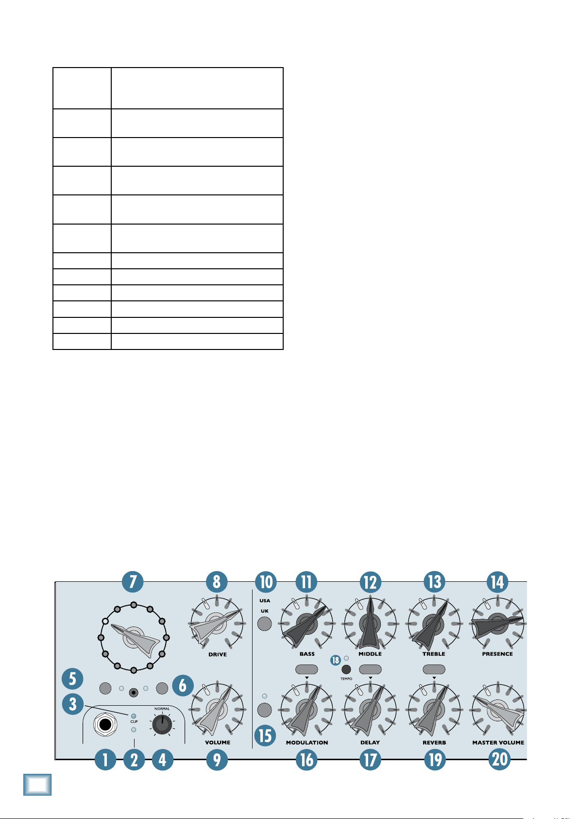
Throughout this section you’ll find illustrations with
each feature numbered. If you want to know more about
a feature, simply locate it on the appropriate illustration, notice the number attached to it, and find that
number in the nearby paragraphs.
This icon marks information that is
-
critically important or unique to the
VT12. For your own good, read them
and remember them. They will be on
the final test.
This icon leads you to in-depth
explanations of features and practical tips. While not mandatory, they
usually have some valuable nugget of
information.
• Cabinet-emulated stereo line outputs.
• Stereo headphone output.
• External speaker jack, for connecting the optional
EX12 extension speaker cabinet.
• Pedal jack, for connecting optional PB-1 and PB-4
pedal boards.
• USB jack — provides streaming audio to PC (cabi
net emulated) for recording applications, and allows for deep editing, preset archiving, live control,
and firmware upgrade functions.
• Seven-ply Italian poplar cabinet construction, for
warm tone and light weight.
• Universal switching power supply.
•
Includes Tracktion Music Production
digital audio recording.
Software for
A PLUG FOR THE CONNECTOR SECTION
Appendix C is a section on connectors: XLR connectors, balanced connectors, unbalanced connectors, and
the insert connectors used on the VT12.
More resources on our website at
www.mackie.com
Visit our website and click “Support.” There you will
find links to the Glossary of Terms (brief explanations
of many pro audio terms), Frequently Asked Questions
(FAQs), and our forums (our online help community).
Now, let’s get started!
6
hotwire VT1
Getting Started
M
O
D
E
HI-FI
JAZZ
ACOUSTIC
HI GAIN I
HI GAIN II
BLUES
LINE
GAIN
SIG
INPUT
CHANNEL
BRIGHTMANUAL
USA II
USA I
UK II
CLASS A
UK I
STYLE
EQ
TYPE TYPE TYPE
EFX
02
READ THIS PAGE!!
4. Turn up the VOLUME and DRIVE controls about
Owner’s Manual
halfway (12 o’clock position). SLOWLY turn up the
MASTER VOLUME control while strumming your
guitar until you hear your guitar, and set it for a
comfortable listening level.
Even if you’re one of those people
who never reads manuals, all we ask
is that you read this page now before
you begin using the VT12. You’ll be
glad you did!
The Hotwire VT12 may seem daunting at first with all
the knobs and buttons on the top panel. However, once
you understand the concept and the signal-flow of the
amplifier, you will see that it operates very much like
any other guitar amplifier. It just has more features and
options to spark your creativity than any other guitar
amp you’ve ever seen.
Input Stage and Hotwire Section
Now that you are getting sound through your amplifier, let’s talk about the Hotwire section. The input stage
of the VT12 is comprised of two 12AX7A vacuum tubes,
with two gain stages per tube (it’s a dual-triode vacuum
tube for those of you interested in such things), for a
total of four vacuum tube gain stages.
The MODE switch is used to rewire the configuration of these four gain stages and, along with carefully
applied EQ voicing, create the different sounds that
represent the many styles of guitar amplifiers that have
been used throughout the years.
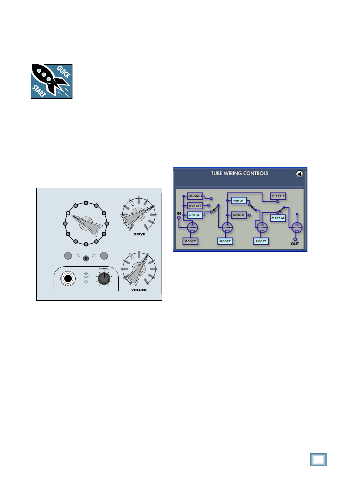
The following screenshot from the VT12 PC application shows a graphical representation of the UKI Mode.
1. Turn down the VOLUME, DRIVE and MASTER VOLUME controls, and set the MODE control to JAZZ.
2. Plug your guitar into the INPUT jack and turn the
POWER switch on.
3.
Set the GAIN control to NORMAL and strum your
guitar. If your guitar has its own volume control(s),
adjust them to where you normally set them when
you play. You should see the yellow SIG LED light,
indicating that the VT12 sees a signal coming from
your guitar. If the SIG LED doesn’t light, try turning
up the GAIN control or the volume control(s) on
your guitar. If the CLIP LED lights continuously or
frequently, turn down the GAIN control or the volume
control(s) on your guitar (it’s okay if the CLIP LED
lights occasionally).
As you switch through the various modes, the switches in the above tube wiring diagram change positions to
represent how the tubes are rewired. In addition, EQ is
applied before and after the tube preamp stage.
There are two more controls to discuss in relation
to the input stage: the DRIVE control and VOLUME
control (we’ll discuss the MANUAL button on page 9;
the BRIGHT button simply adds a fixed mid-to-high-frequency boost to the signal).
The DRIVE control provides additional gain before the
tube stage. You can use this to adjust the amount of analog tube distortion you can hear for the particular mode
you have selected. The more DRIVE, the more distortion.
The VOLUME control adjusts the signal level after the
tube stage and the EQ section (described next). With high
drive levels and high gain modes, you may need to turn the
VOLUME control down to compensate. On the other hand,
with low drive levels and low gain modes, you can turn the
VOLUME control up more for a cleaner sound.
Owner’s Manual
7
EQ and Effects Sections
W
A
T
T
S
8
4
16
30
2
60
1
120
MAINS
CHANNEL
OVERDRIVE LEADCRUNCHCLEAN
SPEAKERNOTCHBUZZ
CLICKCOMP TOOLSTUNERMIC
MODE SWITC HING T UBE A MPLIFI ER
BY
STYLE
EQ
TYPE TYPE TYPE
EFX
SAVE
EXI T
Silver
Surfer
02
W
A
T
T
S
8
4
16
30
2
60
1
120
MAINS
CHANNEL
OVERDRIVE LEADCRUNCHCLEAN
SPEAKERNOTCHBUZZ
CLICKCOMP TOOLSTUNERMIC
MODE SWITC HING T UBE A MPLIFI ER
BY
SAVE
EXI T
Silver
Surfer
02
Silver
Surfer
02
hotwire VT12
The EQ section contains the four EQ controls: BASS,
MIDDLE, TREBLE, and PRESENCE. These controls
come after the tube stage, and provide the opportunity
to adjust the overall sound of the particular mode you
have selected.
The EQ section also has a USA/UK tone stack switch.
This changes the characteristics of the EQ to resemble
either USA or UK style tone controls.
The Effects section contains Modulation, Delay, and
Reverb controls. You can switch the Effects section on
and off with the EFX button next to the MODULATION
control.
Each effect has a number of types you can select by
pressing the TYPE button just above the MODULATION,
DELAY, and REVERB controls. The currently selected
type appears in the display. Rotate the Select/Adjust
knob to change the type of the effect, and press the
Select/Adjust knob to cycle through the parameters for
each effect.
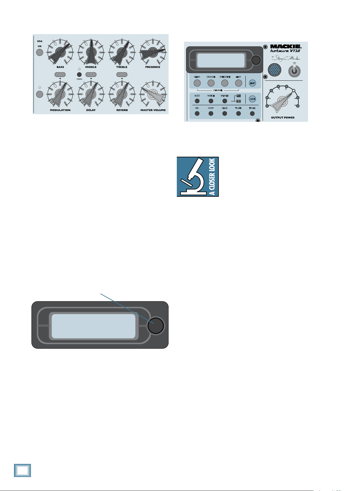
Select/Adjust Knob
Display and Channel Section
The four channel buttons, CLEAN, CRUNCH, OVERDRIVE, and LEAD, give you access to four preset sounds
stored within the current bank.
There are 24 banks of four stored
presets, one for each channel. Change
banks by turning the Select/Adjust
knob next to the display, then press a
channel button to recall the preset for
that bank and channel.
A preset stores the following settings: Mode, Drive,
Volume, EQ, Bass, Middle, Treble, Presence, Modulation,
Delay, Reverb, and Compressor.
You can create your own preset and save it to a bank
and channel using the SAVE button. Refer to page 14 for
more details on how to do this.
There are several miscellaneous buttons in this section, including EXIT, BUZZ, NOTCH, SPEAKER, SAVE,
MIC, COMP, CLICK, TUNER, and TOOLS. These are
described in more detail in the “Display and Channel”
section beginning on page 13.
Finally, the OUTPUT POWER switch allows you to
reduce the amplifier power in 3 dB increments (halving
the power reduces it by 3 dB). As the output power is
reduced, so is the overall volume and the point at which
the amplifier overloads. This allows you to get a “loud”
(i.e., overdrive) sound without having the amplifier
playing loud. Good for practicing and keeping peace
with your neighbors.
The MASTER VOLUME control is also in this section.
It controls the amount of signal that is sent to the power
amplifier section, after the EQ and Effects sections. Use
this to control the overall volume of the amplifier.
That’s it for the Getting Started section. Hopefully,
this has provided enough information to get you well on
your way to enjoying your new Hotwire VT12. The next
section, VT12 Features, goes into more detail describing every input, output, knob, and button on the VT12.
After that, there is a section on the VT12 Control Panel,
which describes how to install the VT12 Control Panel
application on your computer. This provides access to
even more editing and control features than you have
available on the top panel of the VT12.
8
hotwire VT1

Owner’s Manual
M
O
D
E
HI-FI
JAZZ
ACOUSTIC
HI GAIN I
HI GAIN II
BLUES
LINE
GAIN
SIG
INPUT
CHANNEL
OVERDRIVE LEADCRUNCHCLEAN
SPEAKERNOTCHBUZZ
CLICKCOMP TOOLSTUNERMIC
BRIGHTMANUAL
USA II
USA I
UK II
CLASS A
UK I
STYLE
EQ
TYPE TYPE TYPE
EFX
Silver
Surfer
02
VT12 Features
Input Stage and Hotwire Section
1. INPUT
This is where you plug in your guitar or other instrument. It is a 1/4" TS connector that accepts an unbalanced
instrument-level input signal from a high-impedance instrument like a guitar or a line-level signal from
a low-impedance source (LINE mode [7]).
2. SIG
This LED indicates when signal is present at the input
jack. It senses the signal after the input GAIN control,
but before the DRIVE and VOLUME controls.
3. CLIP
The CLIP LED lights when the input preamp reaches
its maximum output and is on the verge of clipping. It’s
okay for the CLIP LED to blink occasionally, but if it is
blinking frequently or continuously, turn down the GAIN
control [4] or the volume control on your instrument.
4. GAIN
The GAIN controls adjust the input sensitivity of the
instrument input. This allows the signal from the outside
world to be adjusted to optimal internal operating levels.
Set the GAIN control to the NORMAL position (12
o’clock). The SIG LED should stay lit while you are playing your instrument. If the SIG LED doesn’t light or blinks
occasionally, turn the GAIN control up. It’s okay if the
CLIP LED blinks occasionally, but if it blinks frequently or
lights continuously, turn the GAIN control down.
5. MANUAL
Push this button to activate manual mode. When
manual mode is active, the LED next to the button
lights
and the display goes blank. All of the channel
presets and effects are bypassed by default when in
manual mode, so only the MODE switch and EQ controls
are active. Use manual mode to simplify the operation of
the VT12 for basic guitar amp operation.
You can reactivate the effects by pressing the EFX
[15] button. The previous effects settings are activated.
You cannot change the effects settings from the VT12
top panel, but you can from the VT12 Control Panel on
your computer.
6. BRIGHT
This button applies a fixed mid/high frequency boost
to the input signal. When Bright is activated, the LED
next to the button lights.
7. MODE Switch
Use the Mode switch to select among 12 different amplifier modes, emulating various classic guitar amplifier
sounds. As described in the “Getting Started” section,
the various sounds are created by “hotwiring” the tube
gain stages into different configurations and levels of
gain, along with applying selected EQ voicings.
Note: You can modify and overwrite a factory mode
setting using the VT12 Control Panel’s FILE button (see
page 22 for more info).
The VT12 has a 12" speaker as well as a 1.35" compression driver. The compression driver and 12
combination
is used for the microphone input and the
Line, Acoustic, and Hi-Fi settings on the Mode switch
and provides a full-range output. The remaining settings
on the Mode switch only use the 12" speaker.
" speaker
Owner’s Manual
9
The following table provides a brief description of
M
O
D
E
HI-FI
JAZZ
ACOUSTIC
HI GAIN I
HI GAIN II
BLUES
LINE
GAIN
SIG
INPUT
CHANNEL
OVERDRIVE LEADCRUNCHCLEAN
SPEAKERNOTCHBUZZ
CLICKCOMP TOOLSTUNERMIC
BRIGHTMANUAL
USA II
USA I
UK II
CLASS A
UK I
STYLE
EQ
TYPE TYPE TYPE
EFX
Silver
Surfer
02
each of the Mode settings:
LINE
Works like a standard line input and
provides a clean signal for keyboards
and other line-level sources.
ACOUSTIC
Provides a voicing optimized for acoustic electric and hybrid guitars.
HI-FI
hotwire VT12
JAZZ
Full-range clean sound for electric
guitar or keyboard.
Warm, dark, and clean sound for jazz
guitar.
BLUES
Brighter sound with a bit of grit, designed to accentuate touch sensitivity.
CLASS A
Pure clean tone ranging to ragged
overdrive.
USA I
USA II
UK I
UK II
HI GAIN I
HI GAIN II
Late-50s “tweed” sound.
Early 60s “black face” sound.
Classic British rock sound.
High gain British rock sound.
West coast high gain sound.
Modern metal sound.
8. DRIVE
control down to compensate. On the other hand, with low
drive levels and low gain modes, you can turn the VOLUME
control up more for a cleaner sound.
EQ and Effects Section
10. USA/UK
The EQ section has a USA/UK tone stack switch. This
changes the characteristics of the EQ to resemble either
USA or UK style tone controls. The UK setting has a bit
more midrange presence. Experiment to find the setting
that you like best for a particular riff or song.
11. BASS
Use this to adjust the output level of the low frequencies of the selected channel. The adjustment range and
frequency is determined by the USA/UK button.
12. MIDDLE
Use this to adjust the output level of the mid frequencies of the selected channel. The adjustment range and
frequency is determined by the USA/UK button.
The Drive control adjusts the amount of gain within
each amplifier mode, just before the tube stage. The
higher the Drive control setting, the more overdrive
sound you can achieve.
9. VOLUME
The Volume control provides the final overall gain for
the signal from the preamp tube stage of the amplifier,
after the Drive and EQ controls.
and high gain modes, you may need to turn the VOLUME
With high drive levels
13. TREBLE
Use this to adjust the output level of the high frequencies. The adjustment range and frequency is determined
by the USA/UK button.
10
hotwire VT1
 Loading...