

Page 1
OWNER’S MANUAL
™
dB
dB
MAIN IN 1
MAIN IN 2
OL
0
STEREO
-6
MONO
-12
-18
-24
-30
PHONES OUTPUT
OL
0
-6
-12
-18
-24
-30
dB
OL
0
IN 1
STEREO
-6
IN 2
MONO
-12
-18
-24
-30
PHONES OUTPUT
dB
OL
0
IN 1
STEREO
-6
IN 2
MONO
-12
-18
-24
-30
PHONES OUTPUT
dB
OL
0
IN 1
STEREO
-6
IN 2
MONO
-12
-18
-24
-30
PHONES OUTPUT
dB
OL
0
IN 1
STEREO
-6
IN 2
MONO
-12
-18
-24
-30
PHONES OUTPUT
dB
OL
0
IN 1
STEREO
-6
IN 2
MONO
-12
-18
-24
-30
PHONES OUTPUT
dB
OL
0
IN 1
STEREO
-6
IN 2
MONO
-12
-18
-24
-30
PHONES OUTPUT
dB
OL
0
IN 1
-6
IN 2
-12
-18
-24
-30
STEREO
MONO
PHONES OUTPUT
IN 1
IN 2
POWER
Page 2
Important Safety Instructions
.
Read these instructions.
2.
Keep these instructions.
3.
Heed all warnings.
4.
Follow all instructions.
5.
Do not use this apparatus near water.
6.
Clean only with a dry cloth.
7.
Do not block any ventilation openings. Minimum distance (5 cm) around
the apparatus for sucient ventilation. The ventilation should not be impeded
by covering the ventilation openings with items, such as newspapers,
table-cloths, curtains, etc. Install in accordance with the manufacturer’s
instructions.
8.
Do not install near any heat sources such as radiators, heat registers, stoves,
or other apparatus (including amplifiers) that produce heat. No naked flame
sources, such as lighted candles, should be placed on the apparatus.
9.
Do not defeat the safety purpose of the polarized or grounding-type plug.
A polarized plug has two blades with one wider than the other. A groundingtype plug has two blades and a third grounding prong. The wide blade or the
third prong are provided for your safety. If the provided plug does not fit into
your outlet, consult an electrician for replacement of the obsolete outlet.
0.
Protect the power cord from being walked on or pinched particularly at plugs,
convenience receptacles, and the point where they exit from the apparatus.
11.
Only use attachments/accessories specified by the manufacturer.
HM Series Headphone Amplifiers
2.
Use only with a cart, stand, tripod, bracket, or table specified
by the manufacturer, or sold with the apparatus. When a
cart is used, use caution when moving the cart/apparatus
combination to avoid injury from tip-over.
3.
Unplug this apparatus during lightning storms or when
unused for long periods of time.
14.
Refer all servicing to qualified service personnel. Servicing is required when
the apparatus has been damaged in any way, such as power-supply cord
or plug is damaged, liquid has been spilled or objects have fallen into the
apparatus, the apparatus has been exposed to rain or moisture, does not
operate normally, or has been dropped.
15.
This apparatus shall not be exposed to dripping or splashing, and no object
filled with liquids, such as vases or beer glasses, shall be placed on the
apparatus.
6.
Do not overload wall outlets and extension cords as this can result in a risk
of fire or electric shock.
7. Warning:
8.
This apparatus has been equipped with a rocker-style AC mains power switch.
This apparatus has been designed with Class I construction and must
beconnected to a mains socket outlet with a protective earthing connection
(the third grounding prong).
This switch is located on the rear panel and should remain readily accessible
to the user.
PORTABLE CART
WARNING
9.
The MAINS plug or an appliance coupler is used as the disconnect device,
so the disconnect device shall remain readily operable.
20.
Max. specified ambient temperature 45˚C. Altitude up to 2000m.
2. NOTE:
This equipment has been tested and found to comply with the limits
for a Class B digital device, pursuant to part 5 of the FCC Rules. These
limits are designed to provide reasonable protection against harmful
interference in a residential installation. This equipment generates, uses,
and can radiate radio frequency energy and, if not installed and used in
accordance with the instructions, may cause harmful interference to radio
communications. However, there is no guarantee that interference will
not occur in a particular installation.If this equipment does cause harmful
interference to radio or television reception, which can be determined by
turning the equipment o and on, the user is encouraged to try to correct
the interference by one or more of the following measures:
• Reorient or relocate the receiving antenna.
• Increase the separation between the equipment and the receiver.
• Connect the equipment into an outlet on a circuit dierent from
that to which the receiver is connected.
• Consult the dealer or an experienced radio/TV technician for help.
CAUTION: Changes or modifications to this device not expressly approved by
LOUD Audio, LLC could void the user’s authority to operate the equipment
under FCC rules.
22.
This apparatus does not exceed the Class A/Class B (whichever is
applicable) limits for radio noise emissions from digital apparatus as set
out in the radio interference regulations of the Canadian Department of
Communications.
ATTENTION
— Le présent appareil numérique n’émet pas de bruits
radioélectriques dépassant las limites applicables aux appareils
numériques de class A/de class B (selon le cas) prescrites dans le
réglement sur le brouillage radioélectrique édicté par les ministere des
communications du Canada.
23.
Exposure to extremely high noise levels may cause permanent hearing loss.
Individuals vary considerably in susceptibility to noise-induced hearing
loss, but nearly everyone will lose some hearing if exposed to suciently
intense noise for a period of time. The U.S. Government’s Occupational
Safety and Health Administration (OSHA) has specified the permissible
noise level exposures shown in the following chart.
According to OSHA, any exposure in excess of these permissible limits
could result in some hearing loss. To ensure against potentially dangerous
exposure to high sound pressure levels, it is recommended that all persons
exposed to equipment capable of producing high sound pressure levels
use hearing protectors while the equipment is in operation. Ear plugs or
protectors in the ear canals or over the ears must be worn when operating
the equipment in order to prevent permanent hearing loss if exposure is in
excess of the limits set forth here:
CAUTION
RISK OF ELECTRIC SHOCK! DO NOT OPEN!
CAUTION: TO REDUCE THE RISK OF ELECTRIC SHOCK DO NOT
REMOVE COVER (OR BACK). NO USER-SERVICEABLE PARTS INSIDE.
REFER SERVICING TO QUALIFIED PERSONNEL.
The lightning flash with arrowhead symbol within
an equilateral triangle is intended to alert the user
to the prescence of uninsulated “dangerous voltage”
within the product’s enclosure, that may be of significant magnitude to
constitute a risk of electric shock to persons.
The exclamation point within an equilateral triangle is
intended to alert the user of the prescence of important
operating and maintaining (servicing) instructions in the
literature accompanying the appliance.
WARNING — To reduce the risk of fire or electric shock,
do not expose this apparatus to rain or moisture.
Correct disposal of this product: This symbol indicates that this product should not be disposed of with your household waste, according to the WEEE
directive (2012/19/EU) and your national law. This product should be handed over to an authorized collection site for recycling waste electrical and
electronic equipment (EEE). Improper handling of this type of waste could have a possible negative impact on the environment and human health due
to potentially hazardous substances that are generally associated with EEE. At the same time, your cooperation in the correct disposal of this product
will contribute to the eective usage of natural resources. For more information about where you can drop o your waste equipment for recycling, please
contact your local city oce, waste authority, or your household waste disposal service.
2
HM Series Headphone Amplifiers
Duration, per
day in hours
8 90 Duo in small club
6 92
4 95 Subway Train
3 97
2 100 Very loud classical music
1.5 102
1 105 Ryan screaming at Troy about deadlines
0.5 110
0.25 or less 115 Loudest par ts at a rock concert
Sound Level dBA,
Slow Response
Typical Example
Page 3

Contents
Owner’s Manual
Features
Important Safety Instructions ........................................ 2
Contents ........................................................................... 3
Features ............................................................................3
Introduction ..................................................................... 3
How To Use This Manual ................................................. 3
Getting Started ................................................................ 4
Things To Remember ....................................................... 4
Hookup Diagrams ............................................................ 5
HM Series Headphone Amps: Rear Panel Features ......7
1. Power Connector and Fuse ................................... 7
2. Voltage Selector Switch ....................................... 7
3. 1/4" Headphone Output Jacks .............................7
4. Main Input Jacks ..................................................8
5. Main Output Jacks ...............................................8
6. Aux Input Jacks [HM-800].................................8
HM Series Headphone Amps: Front Panel Features ..... 9
7. Power Switch and LED ..........................................9
8. Genre Knob ...........................................................9
9. Meters ...................................................................9
10. Main Level Knobs ................................................9
11. 1/4" Headphone Output Jacks ............................9
12. 1/4" Aux Input Jacks ...........................................9
13. Phones Output Knobs .........................................9
14. St. / 2-Ch Switches [HM-400]
Stereo / Mono Switches [HM-800] ................ 10
15. In 1/2 Switches [HM-800] ............................... 10
16. Balance Knobs [HM-400]................................ 10
17. L/R Mute Switches [HM-400] ......................... 10
18. Bass Knobs [HM-400] ..................................... 10
19. Treble Knobs [HM-400] ................................... 10
Appendix A: Service Information ................................... 11
Appendix B: Technical Information ...............................12
HM Series Headphone Amps Dimensions .............13
HM Series Headphone Amps Block Diagrams ......14
Limited Warranty ............................................................16
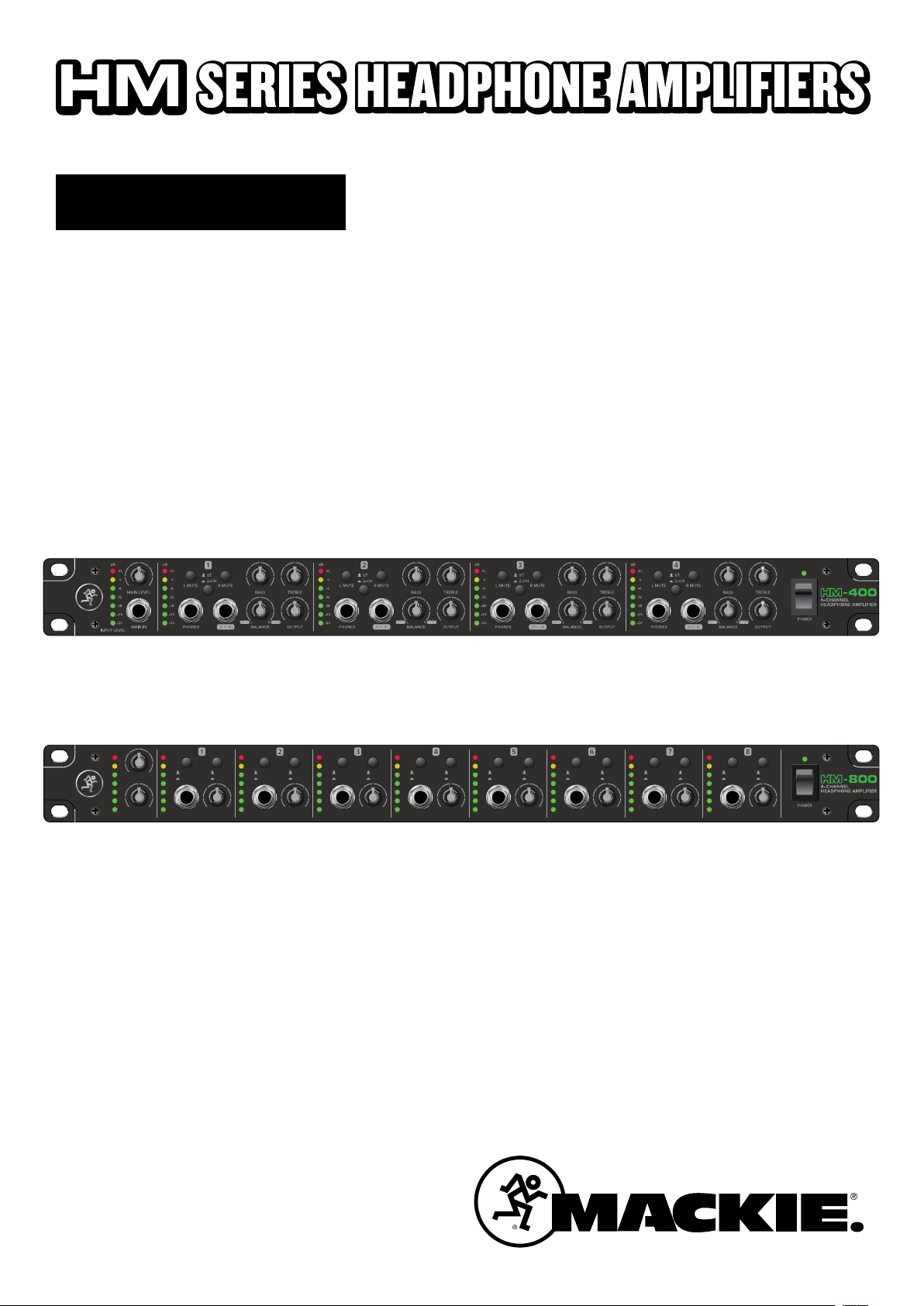
HM-400 Headphone Amplifier
• L/R Main stereo inputs plus L/R stereo outputs
• 7-segment LED metering per channel plus main
• Three headphone outputs per channel
• Aux input on each channel with balance control
to mix main and aux signal
• Mute and stereo/2-ch mode switches per channel
• 12 total headphone outputs
• Built-Like-A-Tank™ construction
HM-800 Headphone Amplifier
• Two discrete main stereo inputs with separate level
control plus stereo outputs
• 7-segment LED metering per channel plus main
• Two headphone outputs per channel
• Eight independent aux inputs for up to eight individual
stereo mixes
• Input Select and Stereo/Mono switches per channel
• 16 total headphone outputs
• Built-Like-A-Tank™ construction
Introduction
HM-400 Headphone Amplifier
The 19" rackmount HM-400 4-Channel Headphone Amplifier
oers an incredible amount of versatility and excellent sound
quality in a single rack space.
Perfect for professional applications including studios,
Houses of Worship, practice spaces, and more. The HM-400
features a main input with level control plus stereo outs, aux
inputs and EQ per channel with 12 total headphone outputs.
HM-800 Headphone Amplifier
The 19" rackmount HM-800 8-Channel Headphone Amplifier
oers up to 10 available mixes with a total of 16 headphone
outputs.
Like us
Follow us
Watch our dang videos
Part No. SW1227 Rev. A 01/18
©2018 LOUD Audio, LLC All Rights Reserved.
Perfect for professional applications including studios,
Houses of Worship, practice spaces, and more. Featuring two
discrete main inputs with level control plus stereo outs, aux
inputs per channel.
How to Use This Manual
Afer this introduction, a getting started guide will help you
set things up fast. The hookup diagrams show typical setups.
This icon marks information that is critically
important or unique to the HM Series Headphone
Amplifier. For your own good, read and remember
them.
Owner’s Manual
3
Page 4

Getting Started
Things to Remember
The following steps will help you set up the HM Series
Headphone Amplifier quickly.
1. Make sure the power switch is o on all connected gear.
2. Turn down all level knobs on all connected gear.
3. Set all channel EQ and Balance knobs at their center
detent [HM-400].
4. Disengage all switches.
5. Connect cables from the output jacks of a mixer,
computer or other audio device to the input jacks
of the HM Series Headphone Amplifier.
6. Connect stereo headphones to the headphone output
jack(s) of the HM Series Headphone Amplifier.
HM Series Headphone Amplifiers
7. Push the line cord securely into the IEC connector
and plug the other end into a grounded AC outlet.
The headphone amp may accept the appropriate voltage
as indicated near the connector.
8. Turn the mixer, computer or audio device’s power
switch on.
• Never listen to loud music for prolonged periods.
Please see the Safety Instructions on page 2 for
information on hearing protection.
• Save the shipping boxes and packing materials!
You may need them someday. Besides, your pet
hamsters will love playing in them and jumping out
at you unexpectedly. Remember to pretend like you
are surprised!
• Save your sales receipt in a safe place.
9. Turn the HM-400 / HM-800 power switch on.
10. Be sure that the volume of the input is the same as it
would be during normal use.
11. Slowly raise the phones knob(s) to a comfortable
listening level.
2. Adjust the EQ knobs to taste [HM-400].
4
HM Series Headphone Amplifiers
Page 5
Hookup Diagrams
dB
OL
0
-6
MAIN LEVEL
-12
-18
-24
-30
MAIN IN PHONES PHONES PHONES PHONES
INPUT LEVEL
4–CHANNEL
HEADPHONE AMPLIFIER
115V
~100-120V /~220-240V 50/ 60Hz 24W
FUSE: T1.0AL 250V for ~100-120V
T0.5AL 250V for ~220-240V
4–CHANNEL
HEADPHONE AMPLIFIER
115V
~100-120V /~220-240V 50/ 60Hz 24W
FUSE: T1.0AL 250V for ~100-120V
T0.5AL 250V for ~220-240V
dB
1 2 3 4
OL
ST.
0
2-CH
-6
-12
-18
-24
-30
4 3 12
PHONES PHONES PHONES PHONES
4 3 1
dB
OL
0
BASS TREBLE
-6
-12
-18
-24
-30
OUTPUT
2
ST.
2-CH
BASS TREBLE
dB
OL
ST.
0
2-CH
L MUTE R MUTEL MUTE R MUTEL MUTE R MUTE L MUTE R MUTE
-6
-12
-18
-24
-30
OUTPUT
BASS TREBLE
Owner’s Manual
MAIN IN LMAIN IN RMAIN OUT LMAIN OUT R
MAIN IN LMAIN IN RMAIN OUT LMAIN OUT RPHONES PHONES PHONES PHONES
dB
OL
ST.
0
2-CH
-6
-12
-18
-24
-30
OUTPUT
BASS TREBLE
4–CHANNEL
HEADPHONE AMPLIFIER
POWER
OUTPUT
MONITOR
MONITOR
MONO
6 5 4
SUBGROUP INSERTS
TIP SEND, RINGRETURN
L
3 2 14
3 2 14
R
AUX INSERTS
TIP SEND, RING RETURN
3 2 1 2 1
AUX SENDS
BAL / UNBAL
3 2 16 5 4
100 - 240 V
50 - 60 Hz 55W
SUBGROUP OUTS
BAL / UNBAL
POWERONPHANTOM
21/22 23/24
INSERTS (TIP SEND, RING RETURN)
BAL / UNBALBAL / UNBAL
20
L
MONO
LINE (BAL / UNBAL)
20
R
STEREO RETURNS
BAL / UNBAL
ONYX MIC PREAMPS
L
MONO
2 1
R
20
TALKBACK
MIC
ON
INSERT LINE
TIP SEND
RING RETURN
BAL / UNBAL BAL / UNBAL BAL / UNBAL
17
18
19
17
18
19
17
18
19
RIGHT
MAIN OUT
INSERT LINE
TIP SEND
RING RETURN
14
15
16
14
15
16
14
15
16
LEFT
MONO
MAIN OUT
INSERT LINE
TIP SEND
RING RETURN
11
12
13
11
12
13
11
12
13
TAPE
MAIN OUT
OUTPUT
L
U
+6
RLR
LEVEL
UNBALANCED
8
9
10
8
9
10
8
9
10
OUTIN
USB
5
6
7
5
6
7
5
6
7
3
4
3
4
3
4
AVIS:
RISQUE DE CHOC ELECTRIQUE — NE PAS OUVRIR
REPLACE WITH THE SAME TYPE FUSE AND RATING.
DISCONNECT SUPPLY CORD BEFORE CHANGING FUSE
THIS DEVICE COMPLIES WITH PART 15 OF THE FCC RULES FOR THE U.S. AND THE ICES-003 FOR
CANADA. OPERATION IS SUBJECT TO THE FOLLOWING TWO CONDITIONS: (1) THIS DEVICE MAY NOT
CAUSE HARMFUL INTERFERENCE, AND (2) THIS DEVICE MUST ACCEPT ANY INTERFERENCE RECEIVED,
INCLUDING INTERFERENCE THAT MAY CAUSE UNDESIRED OPERATION.
INSERTS (TIP SEND, RING RETURN)
2
LINE (BAL / UNBAL)
2
ONYX MIC PREAMPS
2
SERIAL NUMBER
WARNING:
SHOCK, DO NOT EXPOSE THIS EQUIPMENT TO RAIN OR
MOISTURE. DO NOT REMOVE COVER. NO USER SERVICEABLE
PARTS INSIDE. REFER SERVICING TO QUALIFIED PERSONNEL.
UTILISE UN FUSIBLE DE RECHANGE DE MÊME TYPE.
DEBRANCHER AVANT DE REMPLACER LE FUSIBLE
1
1
1
TO REDUCE THE RISK OF FIRE OR ELECTRIC
REVISION
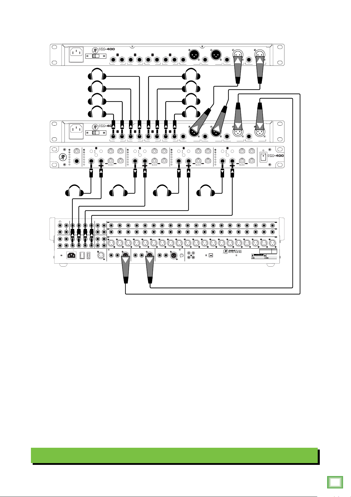
Let’s take a look at a typical hookup diagram for the HM-400, starting with the front panel connections. There
are four channels, so connect a pair of stereo headphones to each headphone out jack. Next, connect cables
between the mixer’s aux out jacks to each HM-400’s 1/4" aux input jacks. There is also a 1/4" main input jack
on the far lef of the HM-400. Feel free to feed a computer or other audio source into this input.
Now let’s look at the rear panel from lef to right. There are eight 1/4" headphone jacks, two for each channel.
Connect as many stereo headphones as necessary to these jacks. Next up are the main output L/R jacks.
These outputs may be connected to the main inputs of an additional HM-400 or to speakers in a live room. On
the far right are the main input jacks. These are typically connected to the main outputs of a mixer, although a
computer or other audio source also works. For convenience, both the main inputs and outputs of the HM-400
contain XLR and 1/4" jacks. You can choose between the XLR or 1/4" inputs, but not both simultaneously. We
appreciate your ability to multi-task, but it’s getting out of hand!
Once the connections are made and the music playing, set the input and output levels as desired, along with
EQ settings, balance and/or main / aux level, stereo / 2-channel switch position, etc.
Typical HM-400 Setup
Owner’s Manual
5
Page 6
Hookup Diagrams Continued...
AUX
8–CHANNEL
INPUTS
HEADPHONE AMPLIFIER
115V
MONITOR
MONITOR
MONO
6 5 4
SUBGROUP INSERTS
TIP SEND, RINGRETURN
3 2 14
L
SUBGROUP OUTS
BAL / UNBAL
3 2 14
R
AUX INSERTS
TIP SEND, RING RETURN
3 2 1 2 1
AUX SENDS
BAL / UNBAL
3 2 16 5 4
100 - 240 V
50 - 60 Hz 55W
POWERONPHANTOM
~100-120V /~220-240V 50/ 60Hz 24W
FUSE: T1.0AL 250V for ~100-120V
T0.5AL 250V for ~220-240V
ON
~100-120V /~220-240V 50/ 60Hz 24W
FUSE: T1.0AL 250V for ~100-120V
T0.5AL 250V for ~220-240V
21/22 23/24
L
MONO
R
STEREO RETURNS
BAL / UNBAL
L
MONO
2 1
R
TALKBACK
MIC
8–CHANNEL
HEADPHONE AMPLIFIER
115V
PHONE
OUT
INSERTS (TIP SEND, RING RETURN)
BAL / UNBALBAL / UNBAL
19
20
LINE (BAL / UNBAL)
19
20
ONYX MIC PREAMPS
19
20
RIGHT
INSERT LINE
TIP SEND
RING RETURN
BAL / UNBAL BAL / UNBAL BAL / UNBAL
AUX
INPUTS
PHONE
OUT
HM Series Headphone Amplifiers
8 7
8 7
18
18
18
MAIN OUT
8 7
8 7
17
17
17
INSERT LINE
TIP SEND
RING RETURN
R
6
4 3
5
6
4 3
5
13
14
15
16
13
14
15
16
13
14
15
16
LEFT
6
6
MONO
MAIN OUT
5
5
INSERT LINE
TIP SEND
RING RETURN
4 3
4 3
MAIN OUT
R
1
2
2
L
1
2
10
11
12
10
11
12
10
11
12
TAPE
OUTIN
OUTPUT
L
U
+6
RLR
LEVEL
UNBALANCED
R
1
2
2
L
1
2
R
2
1
L
L
7
8
9
7
8
9
7
8
9
USB
R
R
2
1
L
L
R
1
L
INSERTS (TIP SEND, RING RETURN)
1
2
3
4
5
6
4
5
6
4
5
6
R
LINE (BAL / UNBAL)
1
2
3
ONYX MIC PREAMPS
1
2
3
SERIAL NUMBER
WARNING:
TO REDUCE THE RISK OF FIRE OR ELECTRIC
SHOCK, DO NOT EXPOSE THIS EQUIPMENT TO RAIN OR
MOISTURE. DO NOT REMOVE COVER. NO USER SERVICEABLE
AVIS:
RISQUE DE CHOC ELECTRIQUE — NE PAS OUVRIR
PARTS INSIDE. REFER SERVICING TO QUALIFIED PERSONNEL.
REPLACE WITH THE SAME TYPE FUSE AND RATING.
UTILISE UN FUSIBLE DE RECHANGE DE MÊME TYPE.
DISCONNECT SUPPLY CORD BEFORE CHANGING FUSE
DEBRANCHER AVANT DE REMPLACER LE FUSIBLE
THIS DEVICE COMPLIES WITH PART 15 OF THE FCC RULES FOR THE U.S. AND THE ICES-003 FOR
CANADA. OPERATION IS SUBJECT TO THE FOLLOWING TWO CONDITIONS: (1) THIS DEVICE MAY NOT
CAUSE HARMFUL INTERFERENCE, AND (2) THIS DEVICE MUST ACCEPT ANY INTERFERENCE RECEIVED,
INCLUDING INTERFERENCE THAT MAY CAUSE UNDESIRED OPERATION.
REVISION
1
L
PC / MAC
dB
dB
OL
OL
0
0
-6
-6
LEVEL
MAIN 1
-12
-12
-18
-18
-24
-24
-30
-30
LEVEL
MAIN 2
dB
1
OL
0
STEREO
IN 1
-6
MONO
IN 2
-12
-18
-24
-30
PHONES
OUTPUT
dB
2
OL
0
STEREO
IN 1
-6
MONO
IN 2
-12
-18
-24
-30
PHONES
OUTPUT
dB
3
OL
0
STEREO
IN 1
-6
MONO
IN 2
-12
-18
-24
-30
PHONES
OUTPUT
dB
4
OL
0
STEREO
IN 1
-6
MONO
IN 2
-12
-18
-24
-30
PHONES
OUTPUT
dB
5
OL
0
STEREO
IN 1
-6
MONO
IN 2
-12
-18
-24
-30
PHONES
OUTPUT
dB
6
OL
0
STEREO
IN 1
-6
MONO
IN 2
-12
-18
-24
-30
PHONES
OUTPUT
dB
7
STEREO
MONO
PHONES
8
OL
0
STEREO
IN 1
IN 2
OUTPUT
IN 1
-6
MONO
IN 2
-12
-18
-24
-30
PHONES
8–CHANNEL
HEADPHONE AMPLIFIER
POWER
OUTPUT
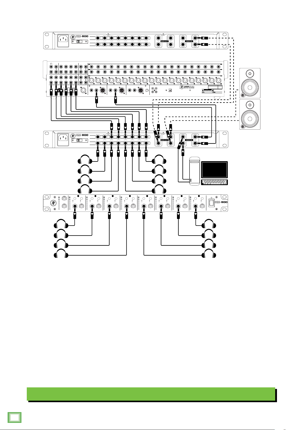
The front panel of the HM-800 has eight headphone output jacks, so connect a pair of stereo headphones
to each channel that will be utilized. Like the front panel, the rear panel of the HM-800 also has eight
headphone output jacks, one for each channel. Again, connect as many headphones as needed to each jack.
Let’s look at the rest of the rear panel from lef to right. Above each headphone output jack is an aux input
jack. These are connected to each aux output jack of the mixer. To the right of the headphone out and aux in
jacks are two pairs of 1/4" main output jacks and two pairs of 1/4" main input jacks.
Here we have L/R output 1 connected to a pair of studio monitors located in a live room, while L/R output 2 is
connected to the main inputs of an additional HM-800. The main input jacks are typically connected to the
main outputs of a mixer (as seen in this illustration), but with an additional pair of input jacks available, we’re
able to connect it to a computer or other audio source’s output jacks.
Once the connections are made and the music playing, set the input and output levels as desired, along with
your choice to hear source input 1 or 2 and listen in stereo or mono. Once an aux source is plugged in, though,
it overrides BOTH main inputs and will be the only available source until the aux cable is removed.
Typical HM-800 Setup
6
HM Series Headphone Amplifiers
Page 7

HM Series Headphone Amplifiers: Rear Panel Features
4–CHANNEL
1
HEADPHONE AMPLIFIER
115V
~100-120V /~220 -240V 50/60Hz 24W
FUSE: T1.0AL 250V for ~100-120V
T0.5AL 250V for ~220-240V
4
2 5 43
PHONES PHONES PHONES PHONES
3 12
Owner’s Manual
MAIN IN LMAIN IN RMAIN OUT LMAIN OUT R
6
6
5
6
5
1
8–CHANNEL
HEADPHONE AMPLIFIER
115V
~100-120V /~220 -240V 50/60Hz 24W
FUSE: T1.0AL 250V for ~100-120V
T0.5AL 250V for ~220-240V
AUX
INPUTS
2
PHONE
8 7
OUT
8 7
3
1. Power Connector and Fuse
Just in case you lose the cord provided with the HM
Series Headphone Amplifer, its power jack accepts a
standard 3-prong IEC cord like those found on most
professional recorders, musical instruments, and
computers.
WARNING: Before you plug the AC power
cord into the HM Series Headphone
Amplifer, you must make sure that
the voltage selector slide switch is set to the
same voltage as the local AC mains supply.
WARNING: Disconnecting the plug’s ground
pin can be dangerous. Don’t do it.
4 3
4 3
R
R
1
2
2
2
L
1
R
2
1
L
L
5 4
R
1
L
2. Voltage Selector Switch
Make sure the switch is in the correct position for
your local AC mains voltage before connecting the AC
power cord. Use a small flat screwdriver to slide the
switch, if required.
The switch allows you to use the HM Series
Headphone Amplifer in dierent countries and
voltages, meet interesting people from other cultures,
and entertain them.
Only slide the voltage switch with the power
cord unplugged.
The fuse is located behind the fuse cover,
at the bottom of the IEC socket.
To remove and replace the fuse:
1. Disconnect the power cord from the IEC socket.
2. Remove the fuse drawer by prying it open
with a small screwdriver. It will slide all the way out.
FUSE
3. Remove the fuse and replace it with an
equivalent-type fuse:
T1.0AL 250 V [~100–120V]
T0.5AL 250 V [~220–240V]
4. Replace the fuse drawer by pushing it all the way
back into the IEC socket.
If two fuses blow in a row, then something is very
wrong. Try a dierent outlet in a totally dierent
location. If fuses continue to blow, see the “Repair”
section on page 11 to find out what to do.
3. 1/4" Headphone Output Jacks
These 1/4" TRS connectors supply the output
for stereo headphones. The volume is controlled
with the phones level knobs on the front panel.
The phones output follows standard conventions:
Tip = Lef channel
Ring = Right channel
Sleeve = Common ground
RING
SLEEVE
SLEEVERING
TIP
WARNING: The headphone amp is loud,
and can cause permanent hearing damage.
Even intermediate levels may be painfully
loud with some headphones. BE CAREFUL! Always
turn the phones level controls all the way down before
connecting headphones or doing anything new that
may aect the headphone volume. Then turn it up
slowly as you listen carefully.
TIP
RING
TIP
SLEEVE
Owner’s Manual
7
Page 8

HM Series Headphone Amplifiers: Rear Panel Features Continued...
2
SHIELD
TIPSLEEVE
SLEEVE
1
HOT
SHIELD
MAIN IN LMAIN IN RMAIN OUT LMAIN OUT R
R
R
R
R
8 7
6
5
4 3
2
1
4. Main Input Jacks
These connectors provide a balanced mic level
signal using an XLR cable or line-level signal using
a 1/4" cable. These input jacks are designed to connect
to the outputs of your favorite DAW and/or mixer.
The balanced XLR jacks, are wired as follows,
according to standards specified by the AES
(Audio Engineering Society):
Balanced XLR Input Connector
Pin 1 – Shield (ground)
Pin 2 – Positive (+ or hot)
Pin 3 – Negative (– or cold)
HOT
HM Series Headphone Amplifiers
1
3
COLD
1
3
2
Balanced XLR Connector
SHIELD
COLD
HOT
5. Main Output Jacks
These connectors provide a balanced mic level
signal using an XLR cable or line-level signal using
a 1/4" cable. These output jacks are designed to
connect to the input jacks of an additional headphone
amplifier and/or powered live room studio monitors
or loudpeakers.
The output connectors and cables are wired the
same as the input connectors and cables as described
and illustrated to the lef, except for the XLR output.
The XLR connector on the HM-400 is male and the
cable will be female.
It is wired as follows, according to standards
specified by the AES (Audio Engineering Society):
Balanced XLR Output Connector
Pin 1 – Shield (ground)
Pin 2 – Positive (+ or hot)
Pin 3 – Negative (– or cold)
The 1/4" TRS and TS jacks, on the other hand, are
wired as follows, according to standards specified by
the AES (Audio Engineering Society):
Balanced 1/4" TRS Input Connector
Tip = Positive (+ or hot)
Ring = Negative (– or cold)
Sleeve = Shield or ground
SLEEVERING
TIP
TIP
RING
TIP
SLEEVE
RING
SLEEVE
Balanced 1/4" Connector
Unbalanced 1/4" TS Input Connector
Tip = Positive (+ or hot)
Sleeve = Shield or ground
3
COLD
2
HOT
1
3
2
Balanced XLR Connector
HM-400 I/O:
One Main In L/R (XLR and 1/4")
One Main Out L/R (XLR and 1/4")
5 4
HM-800 I/O:
Two Main Ins L/R (1/4" Only)
Two Main Outs L/R (1/4" Only)
R
R
2
R
2
1
SHIELD
COLD
R
1
Unbalanced 1/4" Connector
NEVER connect the output of an
amplifier directly to the HM Series
Headphone Amplifer’s input jack.
This could damage the input circuitry!
8
HM Series Headphone Amplifiers
TIP
TIP
SLEEVE
L
L
5 4
L
6. Aux Input Jacks [HM-800]
L
The aux input jacks on the rear panel of the HM-800
work exactly the same as the aux input jacks on the
front panel of the HM-400. Please see call-out #12 on
the following page for a description.
AUX
INPUTS
6
Page 9

HM Series Headphone Amplifiers: Front Panel Features
Owner’s Manual
10
dB
Country
Reggae
Blues
PopRap
Funk
Metal
GENRE
INPUT LEVEL
dB
Country
Reggae
Blues
PopRap
Funk
Metal
GENRE
dB
1 2 3 4
OL
0
-6
-12
-18
-24
-30
OL
0
-6
-12
-18
-24
-30
OL
ST.
0
2-CH
-6
MAIN LEVEL
-12
-18
-24
-30
MAIN IN PHONES PHONES PHONES PHONES
dB
1
OL
0
STEREO
-6
LEVEL
MONO
MAIN 1
-12
-18
-24
-30
LEVEL
PHONES
MAIN 2
OUTPUT
BASS TREBLE
14
dB
OL
0
STEREO
IN 1
-6
MONO
IN 2
-12
-18
98
-24
-30
PHONES
dB
OL
0
-6
-12
-18
98
-24
-30
OUTPUT
15
dB
2
OL
0
IN 1
-6
IN 2
-12
-18
-24
-30
OUTPUT
STEREO
MONO
PHONES
ST.
2-CH
3
OUTPUT
1717
18
BASS TREBLE
1211 13
16
dB
OL
0
STEREO
IN 1
-6
MONO
IN 2
-12
-18
-24
-30
PHONES
11
7. Power Switch and LED
Press the top of this rocker switch inwards to turn
on the HM Series Headphone Amplifier. The power LED
right above the switch will glow with happiness, or at
least it will if you have the headphone amp plugged in
to a suitable live AC mains supply.
Press the bottom of this switch in to turn the HM
Series Headphone Amplifier o. If the amp will not be
used for some time, we suggest unplugging the amp
from the AC outlet, too.
19
OUTPUT
4
IN 1
IN 2
OUTPUT
14
dB
OL
ST.
0
2-CH
L MUTE R MUTEL MUTE R MUTEL MUTE R MUTE L MUTE R MUTE
-6
-12
-18
-24
-30
dB
5
OL
0
STEREO
-6
MONO
-12
-18
-24
-30
PHONES
OUTPUT
BASS TREBLE
dB
OL
0
STEREO
IN 1
-6
MONO
IN 2
-12
-18
-24
-30
PHONES
dB
OL
0
-6
-12
-18
-24
-30
OUTPUT
dB
6
OL
0
IN 1
-6
IN 2
-12
-18
-24
-30
OUTPUT
PHONES
STEREO
MONO
ST.
2-CH
7
OUTPUT
BASS TREBLE
dB
OL
0
STEREO
IN 1
-6
MONO
IN 2
-12
-18
-24
-30
PHONES
10. Main Level Knobs
The main knobs control the level of the signal
fed into the main input(s). This allows signals from
the outside world to be adjusted at optimal internal
operating levels.
The main input jacks on both models are on the
rear panel, although the HM-400 has an additional
1/4" main input jack on the front panel. There is
one main level knob on the HM-400 and two on
the HM-800.
4–CHANNEL
HEADPHONE AMPLIFIER
POWER
OUTPUT
79
8
IN 1
IN 2
OUTPUT
POWER
8–CHANNEL
HEADPHONE AMPLIFIER
79 10 13
8. Genre Knob
Both the HM-400 and HM-800 have a genre knob on
the far lef of the front panel. It streams music through
the headphone outputs based on the chosen genre and
is typically used during breaks in the session. A really
cool feature about this is setting the knob between two
of the listed genres to hear a crossover of both... that
reggae-country sure is weird.
9. Meters
These seven-segment meters display the input and
output signal levels.
These meters should remain green with the
occasional bump into the yellow zone. If there is too
much yellow (or any red clipping), lower the input and/
or output knob(s) until it’s gone. You might check the
EQ settings, as well [HM-400].
Input and output meters (starting at the top):
OL, 0 dB, –6 dB, –12 dB, –18 dB, –24 dB and –30 dB
Both models have one input level meter.
The HM-400 has four output level meters
and the HM-800 has eight.
11. 1/4" Headphone Output Jacks
The headphone output jacks on the front panel work
exactly the same as the headphone output jacks on
the rear panel. Please see call-out #3 on page 7 for a
description.
12. 1/4" Aux Input Jacks
Each aux input jack of the HM Series Headphone
Amplifier may be fed additional input stereo signals
from the aux outputs – also know as aux sends – from
an external mixer. The HM-400 has four of these aux
input jacks (on the front panel) while the HM-800
possesses eight of them (on the rear panel, see
call-out #6 on the previous page).
13. Phones Output Knobs
These knobs are used to adjust the volumes at
the phones outputs from minimum to maximum gain.
The HM-400 has four of these output knobs while
the HM-800 possesses eight of them.
WARNING: Yes, we just mentioned this
exact same warning a couple pages back,
but that is how important this is...the
headphone amp is loud, and can cause permanent
hearing damage. Even intermediate levels may be
painfully loud with some headphones. BE CAREFUL!
Always turn this control all the way down before
connecting headphones or doing anything new that
may aect the headphone volume. Then turn it up
slowly as you listen carefully.
Owner’s Manual
9
Page 10

HM Series Headphone Amplifiers: Front Panel Features Continued...
dB
OL
0
-6
-12
-18
-24
-30
dB
OL
0
-6
-12
-18
-24
-30
PHONES PHONES PHONES
BASS TREBLE
OUTPUT
BASS TREBLE
OUTPUT
ST.
2-CH
ST.
2-CH
L MUTE R MUTEL MUTE R MUTE
2 3 4
14. St. / 2-Ch Switches [HM-400]
Stereo / Mono Switches [HM-800]
When this switch is engaged, the stereo signal
(of that channel) becomes monophonic. The HM-400
has four of these switches while the HM-800 has
eight. Engaged switches will illuminate orange.
15. In 1/2 Switches [HM-800]
Each of the eight channels on the HM-800 have
an in(put) 1/2 switch. Here you are able to choose
whether to listen to input (switch disengaged)
or input 2 (switch engaged). Engaged switches will
illuminate red.
HM Series Headphone Amplifiers
17
L MUTE R MUTE
PHONES
16. Balance Knobs [HM-400]
The HM-400 has a stereo balance knob on each
of the four channels and it serves a dual-purpose.
17
1
ST.
2-CH
14
16
HM-400 Front Panel
18
BASS TREBLE
19
OUTPUT
17. L/R Mute Switches [HM-400]
Mute switches do just what they sound like they do.
They turn o the signal by “routing” it into oblivion.
Instead of muting the entire signal, though, you’re able
to mute just the lef signal or just the right signal...
or we suppose you
could
mute both if you’re so
inclined, but we’re not sure why you would do that!
Simply push a switch in to mute. Engaged switches
will illuminate red.
18. Bass Knobs [HM-400]
Each of the four channels on the HM-400 have
a bass knob. Here you’re able to boost (to the right)
or cut (to the lef) the low frequencies to enhance
the sound of each channel.
We’ve designed a lot of boost and cut into the
equalizer circuit because we know everyone will
occasionally need that. But if you max the EQs, you’ll
likely get mix mush. Equalize subtly and use the lef
sides of the EQ (cut), as well as the right (boost).
19. Treble Knobs [HM-400]
Each of the four channels on the HM-400 also have
a treble knob. Here you’re able to boost (to the right)
or cut (to the lef) the high frequencies to enhance
the sound of each channel.
10
If an aux input IS NOT in use...
...it is a standard balance knob. They allow you
to adjust how much of the lef or right output signals
are heard in the headphones. Turn the knobs lef
or right to make adjustments. Center it to hear
the output equally from the lef and right sides.
The balance control employs a design called
“Constant Loudness.” If a channel is panned hard
lef (or right) and then centered, the signal is
attenuated 3 dB to maintain the same apparent
loudness. Otherwise, the sound would appear
much louder when centered.
If an aux input IS in use...
...it becomes a mix / ratio knob. They allow you
to adjust how much of the aux (lef) or main (right)
input signals are heard in the headphones. Turn the
knobs lef or right to make adjustments. Center it
to hear the aux and main inputs equally.
HM Series Headphone Amplifiers
We’ve designed a lot of boost and cut into the
equalizer circuit because we know everyone will
occasionally need that. But if you max the EQs, you’ll
likely get mix mush. Equalize subtly and use the lef
sides of the EQ (cut), as well as the right (boost).
Page 11

Appendix A: Service Information
Owner’s Manual
If you think your HM Series Headphone Amplifier has a
problem, please check out the following troubleshooting tips and
do your best to confirm the problem. Visit the Support section
of our website (www.mackie.com/support) where you will
find lots of useful information such as FAQs and other
documentation. You may find the answer to the problem without
having to part with your HM Series Headphone Amplifier.
Troubleshooting
No power
• Our favorite question: Is it plugged in? Make sure
the AC outlet is live [check with a tester or lamp].
• Our next favorite question: Is the power switch
on? If not, try turning it on.
• Make sure the line cord is securely seated in the
line cord socket and plugged all the way into the
AC outlet.
Hum
• Use balanced connections throughout your system
for the best noise rejection.
• Whenever possible, plug all the audio equipment’s line
cords into outlets which share a common ground.
The distance between the outlets and the common
ground should be as short as possible.
Repair
For warranty service, refer to the warranty information
on page 16.
Non-warranty service is available at a factory-authorized
service center. To locate the nearest service center, visit
www.mackie.com/support/service-locator. Service for
HM Series Headphone Amplifiers living outside the United
States may be obtained through local dealers or distributors.
• Is the power LED on the front panel illuminated?
If not, make sure the AC outlet is live. If so, refer
to “No sound” below.
• The fuse may have blown. If you suspect a blown fuse,
please see the fuse replacement instructions on page 7.
No sound
• Are the input and/or output level knobs turned all the way
down? Verify that all the volume controls in the system
are properly adjusted. Look at the meters to ensure
that the headphone amp is receiving a signal.
• Is the signal source working? Make sure the connecting
cables are in good repair and securely connected at both
ends. Make sure the output level control on the mixing
console is turned up suciently.
• Make sure the mixer does not have a mute on or a
processor loop engaged. If you find something like this,
make sure the level is turned down before disengaging
the oending switch.
Poor sound
• Is it loud and distorted? Make sure that you’re not
overdriving a stage in the signal chain. Verify that
all level controls are set properly.
If you do not have access to our website, please call our Tech
Support department at 1-800-898-3211 (normal business hours,
Pacific Time), to explain the problem. They will tell you where
the nearest factory-authorized service center is located in your
area.
Please write the serial numbers here for future reference
(i.e., insurance claims, tech support, return authorization,
make dad proud, etc.)
Purchased at:
Date of purchase:
• Be sure all connections are secure.
Owner’s Manual
11
Page 12

Appendix B: Technical Information
HM Series Headphone Amplifiers Specifications
Audio Performance
Frequency Response 20 Hz – 20 kHz, ±1 dB
Noise –66 dB [HM-400]
Distortion (THD)
+4 dBu, 1 kHz, unity gain <0.01% [HM-400]
<0.005% [HM-800]
Maximum Levels
Main Input +15 dBu balanced / unbalanced [HM-400]
+19 dBu balanced / unbalanced [HM-800]
Aux Input +20 dBu unbalanced
Headphone Output 550 mW / channel @ 47
CMRR (Main Input) >42 dB @1 kHz [HM-400]
HM Series Headphone Amplifiers
Gain Range (Main Input) –66 to 18 dBu [HM-400]
>52 dB @1 kHz [HM-800]
–67 to 19 dBu [HM-800]
Input / Output
Input Type Female XLR Balanced
Female 1/4" Balanced – Unbalanced
Main Input Impedance 20 k balanced, 10 k unbalanced [HM-400]
40 k balanced, 20 k unbalanced [HM-800]
Aux Input Impedance 10 k
Output Type Male XLR Balanced
Female 1/4” Balanced – Unbalanced
Headphone Output Impedance 3
unbalanced [HM-400]
13 k unbalanced [HM-800]
–70 dB [HM-800]
(+21 dBu)
unbalanced
Power Requirements
Detachable line cord ~100 – 120V, 50/60 Hz, 24 W
~220 – 240V, 50/60 Hz, 24 W
AC Connector 3-pin IEC 250 VAC, 10 A male
Display LEDs
Front power on/o,
Front input level meter
Front output level meters
L/R mute switches [HM-400]
St. / 2-Ch switches [HM-400]
Stereo / Mono switches [HM-800]
In 1/2 switches [HM-800]
Physical Properties
Height 1.8 in / 46 mm
Width 19.0 in / 483 mm
Depth 8.8 in / 224 mm
Weight 8.0 lb / 3.6 kg
Disclaimer
Since we are always striving to make our products better by incorporating new
and improved materials, components, and manufacturing methods, we reserve
the right to change these specifications at any time without notice.
The “Running Man” figure is a registered trademark of LOUD Audio, LLC.
All other brand names mentioned are trademarks or registered trademarks
of their respective holders, and are hereby acknowledged.
©2018 LOUD Audio, LLC
All Rights Reserved.
12
HM Series Headphone Amplifiers
Page 13

HM-400 Dimensions
WEIGHT
8.0 lb
3.6 kg
Owner’s Manual
8.8 in
224 mm
1.8 in
46 mm
19.0 in / 483 mm
HM-800 Dimensions
WEIGHT
8.0 lb
3.6 kg
8.8 in
224 mm
1.8 in
46 mm
19.0 in / 483 mm
Owner’s Manual
13
Page 14

HM-400 Block Diagram
①
HEADPHONE
HEADPHONE
HEADPHONE
PHONE JACK
PHONE JACK
FIXED RESISTANCE
FIXED RESISTANCE
FIXED RESISTANCE
LINE AMP
LA
LINE AMP
HM Series Headphone Amplifiers
LA
LA
LINE AMP
CAP
FIXED RESISTANCEFIXED RESISTANCE
5
1
3
L MUTE
2
METER
LA
LINE AMP
PHONE JACK.
FIXED RESISTANCE
FIXED RESISTANCE
FIXED RESISTANCE
FIXED RESISTANCE
FIXED RESISTANCE
LINE AMP
LINE AMP
LA
LA
LA
LINE AMP
OUTPUT LEVEL CONTROL
CAP
STEREO/MONO
FIXED RESISTANCE
6
4
FIXED RESISTANCE
1
3
R MUTE
2
②
HEADPHONE
HEADPHONE
HEADPHONE
PHONE JACK
PHONE JACK
FIXED RESISTANCE
FIXED RESISTANCE
FIXED RESISTANCE
LINE AMP
LA
LINE AMP
LA
LA
LINE AMP
CAP
FIXED RESISTANCEFIXED RESISTANCE
5
1
3
L MUTE
2
METER
LA
LINE AMP
PHONE JACK.
FIXED RESISTANCE
FIXED RESISTANCE
FIXED RESISTANCE
FIXED RESISTANCE
FIXED RESISTANCE
LINE AMP
LINE AMP
LA
LA
LA
LINE AMP
OUTPUT LEVEL CONTROL
CAP
STEREO/MONO
FIXED RESISTANCE
6
4
FIXED RESISTANCE
1
3
R MUTE
2
HEADPHONE
PHONE JACK
LINE AMP
③
HEADPHONE
HEADPHONE
PHONE JACK
FIXED RESISTANCE
FIXED RESISTANCE
FIXED RESISTANCE
LINE AMP
LA
LA
LA
LINE AMP
CAP
FIXED RESISTANCEFIXED RESISTANCE
5
1
3
L MUTE
2
METER
LA
LINE AMP
PHONE JACK.
FIXED RESISTANCE
FIXED RESISTANCE
FIXED RESISTANCE
FIXED RESISTANCE
FIXED RESISTANCE
LINE AMP
LINE AMP
LA
LA
LA
LINE AMP
OUTPUT LEVEL CONTROL
CAP
STEREO/MONO
FIXED RESISTANCE
6
4
FIXED RESISTANCE
1
3
R MUTE
2
HEADPHONE
PHONE JACK
LINE AMP
④
HEADPHONE
HEADPHONE
PHONE JACK
FIXED RESISTANCE
FIXED RESISTANCE
FIXED RESISTANCE
LINE AMP
LA
LA
LA
LINE AMP
CAP
FIXED RESISTANCEFIXED RESISTANCE
5
1
3
L MUTE
2
METER
LA
LINE AMP
PHONE JACK.
FIXED RESISTANCE
FIXED RESISTANCE
FIXED RESISTANCE
FIXED RESISTANCE
FIXED RESISTANCE
LINE AMP
LINE AMP
LA
LA
LA
LINE AMP
OUTPUT LEVEL CONTROL
CAP
STEREO/MONO
FIXED RESISTANCE
6
4
FIXED RESISTANCE
1
3
R MUTE
2
TREBLE
BASS
AUX IN
的左右声道,
BALANCE
Analog switch
AUX INPUT
CHANNEL R
CHANNEL L
PHONE JACK
与
MAIN IN
MAIN IN
是控制
是控制
BALANCE
BALANCE
�入�,
�入�,
AUX
AUX
有
当无
Analog switch
LINE AMP
TREBLE
BASS
BALANCE
Analog switch
AUX INPUT
PHONE JACK
BASS TREBLE
BALANCE
Analog switch
AUX INPUT
PHONE JACK
TREBLE
BASS
BALANCE
AUX INPUT
PHONE JACK
LA
FIXED RESISTANCE
FIXED RESISTANCE
MAIN IN LEVEL
LA
LINE AMP
CAP
LA
LINE AMP
CAP
MAIN IN METER
14
XLR
1
3
2
MAIN OUT L
XLR
1
2
3
PHONE JACK
MAIN IN L
HM Series Headphone Amplifiers
BALANCED INPUT
PHONE JACK
DIRECT INPUT
BALANCED INPUT
CAP
CAP
XLR
1
3
2
PHONE JACK
PHONE JACK
MAIN IN R
XLR
1
2
3
PHONE JACK
MAIN OUT R
Page 15

HM-800 Block Diagram
⑧
Owner’s Manual
①
HEADPHONE
HEADPHONE
PHONE JACK
FIXED RESISTANCE
FIXED RESISTANCE
FIXED RESISTANCE
LINE AMP
LA
LINE AMP
LA
LA
LINE AMP
CAP
FIXED RESISTANCEFIXED RESISTANCE
5
METER
LA
LINE AMP
PHONE JACK.
FIXED RESISTANCE
FIXED RESISTANCE
FIXED RESISTANCE
FIXED RESISTANCE
FIXED RESISTANCE
LINE AMP
LINE AMP
LA
LA
LA
LINE AMP
OUTPUT LEVEL CONTROL
CAP
STEREO/MONO
FIXED RESISTANCE
6
4
FIXED RESISTANCE
FIXED RESISTANCE
FIXED RESISTANCE
LA
LINE AMP
LINE AMP
FIXED RESISTANCE FIXED RESISTANCE
②
HEADPHONE
HEADPHONE
METER
LA
PHONE JACK
LINE AMP
LA
CAP
LINE AMP
PHONE JACK.
FIXED RESISTANCE
FIXED RESISTANCE
FIXED RESISTANCE
FIXED RESISTANCE
FIXED RESISTANCE FIXED RESISTANCE
LINE AMP
LA
5
LINE AMP
LA
LA
LA
LINE AMP
OUTPUT LEVEL CONTROL
CAP
STEREO/MONO
FIXED RESISTANCE
6
4
FIXED RESISTANCE
FIXED RESISTANCE
LA
LINE AMP
LINE AMP
③
HEADPHONE
HEADPHONE
METER
LA
PHONE JACK
FIXED RESISTANCE
FIXED RESISTANCE
LINE AMP
LA
CAP
FIXED RESISTANCE FIXED RESISTANCE
LINE AMP
PHONE JACK.
FIXED RESISTANCE
FIXED RESISTANCE
FIXED RESISTANCE
FIXED RESISTANCE FIXED RESISTANCE
LINE AMP
LA
5
LINE AMP
LA
LA
LA
LINE AMP
OUTPUT LEVEL CONTROL
CAP
STEREO/MONO
FIXED RESISTANCE
6
4
FIXED RESISTANCE
FIXED RESISTANCE
LA
LINE AMP
LINE AMP
④
HEADPHONE
HEADPHONE
METER
LA
PHONE JACK
FIXED RESISTANCE
LINE AMP
LA
CAP
FIXED RESISTANCE FIXED RESISTANCE
LINE AMP
PHONE JACK.
FIXED RESISTANCE
FIXED RESISTANCE
FIXED RESISTANCE
FIXED RESISTANCE
FIXED RESISTANCE FIXED RESISTANCE
LINE AMP
LA
5
LINE AMP
LA
LA
LA
LINE AMP
.
. . . .
OUTPUT LEVEL CONTROL
CAP
STEREO/MONO
FIXED RESISTANCE
6
4
FIXED RESISTANCE
.
DIRECT INPUT
PHONE JACK
2
IN1/IN2
1
354
6
2 CHANNEL R
2 CHANNEL L
1 CHANNEL R
1 CHANNEL L
LINE AMP
DIRECT INPUT
PHONE JACK
2
5
IN1/IN2
1
3
4
6
LA
FIXED RESISTANCE
FIXED RESISTANCE
MAIN IN 1 LEVEL
PHONE JACK
MAIN OUT 1 L
LA
LINE AMP
CAP
BALANCED INPUT
PHONE JACK
MAIN IN 1 L
LA
LINE AMP
CAP
BALANCED INPUT
PHONE JACK
MAIN IN 1 R
MAIN IN METER
PHONE JACK
MAIN OUT 1 R
DIRECT INPUT
PHONE JACK
2
5
IN1/IN2
1
3
4
6
LINE AMP
LA
FIXED RESISTANCE
FIXED RESISTANCE
MAIN IN 2 LEVEL
PHONE JACK
MAIN OUT 2 L
LINE AMP
LA
CAP
BALANCED INPUT
PHONE JACK
MAIN IN 2 L
LINE AMP
LA
CAP
BALANCED INPUT
PHONE JACK
MAIN IN 2 R
DIRECT INPUT
PHONE JACK
2
5
IN1/IN2
1
3
4
6
PHONE JACK
MAIN OUT 2 R
Owner’s Manual
15
Page 16

Limited Warranty
Please keep your sales receipt in a safe place.
This Limited Product Warranty (“Product Warranty”) is provided by LOUD Audio, LLC (“LOUD”) and is applicable to products
purchased in the United States or Canada through a LOUD-authorized reseller or dealer. The Product Warranty will not extend
to anyone other than the original purchaser of the product (hereinafer, “Customer,” “you” or “your”).
For products purchased outside the U.S. or Canada, please visit www.mackie.com to find contact information for your local
distributor, and information on any warranty coverage provided by the distributor in your local market.
LOUD warrants to Customer that the product will be free from defects in materials and workmanship under normal use
during the Warranty Period. If the product fails to conform to the warranty then LOUD or its authorized service representative
will at its option, either repair or replace any such nonconforming product, provided that Customer gives notice of the
noncompliance within the Warranty Period to the Company at: www.mackie.com or by calling LOUD technical support
at 1.800.898.3211 (toll-free in the U.S. and Canada) during normal business hours Pacific Time, excluding weekends
or LOUD holidays. Please retain the original dated sales receipt as evidence of the date of purchase. You will need it
HM Series Headphone Amplifiers
to obtain any warranty service.
For full terms and conditions, as well as the specific duration of the Warranty for this product, please visit www.mackie.com.
The Product Warranty, together with your invoice or receipt, and the terms and conditions located at www.mackie.com
constitutes the entire agreement, and supersedes any and all prior agreements between LOUD and Customer related
to the subject matter hereof. No amendment, modification or waiver of any of the provisions of this Product Warranty
will be valid unless set forth in a written instrument signed by the party to be bound thereby.
16
Need help with the HM Series Headphone Amplifier?
• Visit www.mackie.com/support to find: FAQs, manuals, addendums, and other documents.
• Email us at: www.mackie.com/support-contact
• Telephone 1-800-898-3211 to speak with one of our splendid technical support chaps
(Monday through Friday, normal business hours, Pacific Time).
HM Series Headphone Amplifiers
Page 17

16220 Wood-Red Road NE
Woodinville, WA 98072 • USA
Phone: 425.487.4333
Toll-free: 800.898.3211
Fax: 425.487.4337
www.mackie.com
 Loading...