

Page 1
HDR 24HDR 24
HDR 24/96
HDR 24HDR 24
Operation Guide
24 TRACK/24 BIT, DIGITAL AUDIO HARD DISK RECORDER AND EDITOR
Page 2
CAUTION AVIS
RISK OF ELECTRIC SHOCK
DO NOT OPEN
RISQUE DE CHOC ELECTRIQUE
NE PAS OUVRIR
CAUTION: TO REDUCE THE RISK OF ELECTRIC SHOCK
DO NOT REMOVE COVER (OR BACK)
NO USER-SERVICEABLE PARTS INSIDE
REFER SERVICING TO QUALIFIED PERSONNEL
ATTENTION: POUR EVITER LES RISQUES DE CHOC
ELECTRIQUE, NE PAS ENLEVER LE COUVERCLE. AUCUN
ENTRETIEN DE PIECES INTERIEURES PAR L’USAGER. CONFIER
L’ENTRETIEN AU PERSONNEL QUALIFIE.
AVIS: POUR EVITER LES RISQUES D’INCENDIE OU
HDR 24/96
D’ELECTROCUTION, N’EXPOSEZ PAS CET ARTICLE
A LA PLUIE OU A L’HUMIDITE
The lightning flash with arrowhead symbol within an equilateral
triangle is intended to alert the user to the presence of uninsulated
"dangerous voltage" within the product’s enclosure, that may be
of sufficient magnitude to constitute a risk of electric shock to persons.
Le symbole clair avec point de fl che l’int rieur d’un triangle
quilat ral est utilis pour alerter l’utilisateur de la pr sence
l’int rieur du coffret de "voltage dangereux" non isol d’ampleur
suffisante pour constituer un risque d’ l ctrocution.
The exclamation point within an equilateral triangle is intended to
alert the user of the presence of important operating and maintenance
(servicing) instructions in the literature accompanying the appliance.
Le point d’exclamation l’int rieur d’un triangle quilat ral est
employ pour alerter les utilisateurs de la pr sence d’instructions
importantes pour le fonctionnement et l’entretien (service) dans le
livret d’instruction accompagnant l’appareil.
Important Safety Instructions
1. Read Instructions — Read, understand and follow all safety and operating
instructions before using the HDR24/96.
2. Retain Instructions — Keep these safety and operating instructions for future
reference.
3. Heed Warnings — Follow all warnings on the HDR24/96 and in these
operating instructions.
4. Water and Moisture — Do not use the HDR24/96 near water – for example,
near a bathtub, kitchen sink, garden hose, incontinent poodle, sweaty
drummer, etc. – or when condensation has formed on the unit.
5. Cleaning — Clean only with a dry cloth.
6. Heat and Ventilation — Locate the HDR24/96 away from heat sources such
as radiators, campfires, compost pits, heliarc welders, magma flows, etc. Do
not block HDR24/96 ventilation openings or install in spaces that prevent
adequate air circulation to the unit.
7. Power Sources — Connect the HDR24/96 only to a power source of the type
described in these operating instructions or as marked on the HDR24/96.
8. Power Cord Protection — Route power supply cords so that they are not likely
to be walked upon, tripped over, or abraded by items placed upon or against
them. Pay particular attention to cords at plugs, convenience receptacles, and
the point where they exit the HDR24/96.
9. Object and Liquid Entry — Do not drop objects or spill liquids into the
HDR24/96. Clean only with a dry cloth; do not clean with liquid or aerosol
cleaners.
PORTABLE CART WARNING
Carts and stands - The
Component should be used
only with a cart or stand
that is recommended by
the manufacturer.
A Component and cart
combination should be
moved with care. Quick
stops, excessive force, and
uneven surfaces may cause
the Component and cart
combination to overturn.
2
HDR 24/96
10.
Attachments — Use the HDR24/96 with only the accessories specified in
this manual.
11.
Damage Requiring Service — The HDR24/96 should be serviced only by
qualified service personnel when:
A. The power supply cord or the plug has been damaged; or
B. Objects have fallen onto, or liquid has spilled into the unit; or
C. The unit has been exposed to rain or water; or
D. The unit does not appear to operate normally or exhibits a marked
change in performance; or
E. The unit has been dropped, or its chassis damaged.
12.
Servicing — Do not attempt to service the HDR24/96. All servicing
should be referred to the Mackie Service Department.
13.
Power Precaution — Unplug the HDR 24/96 during lightning storms or
when unused for long periods of time. Note that this Mackie product is not
completely disconnected from the AC mains service when the power switch
is in the OFF position.
14.
Grounding and Polarization — To prevent electric shock, do not use the
HDR24/96 polarized plug with an extension cord, receptacle or other
outlet unless the blades can be fully inserted to prevent blade exposure.
Do not defeat the HDR24/96 grounding by plugging into an ungrounded
receptacle or ground lift adapter.
This apparatus does not exceed the Class A/Class B (whichever is applicable)
limits for radio noise emissions from digital apparatus as set out in the radio
interference regulations of the Canadian Department of Communications.
ATTENTION — Le présent appareil numérique n’émet pas de bruits
radioélectriques dépassant las limites applicables aux appareils numériques de
class A/de class B (selon le cas) prescrites dans le réglement sur le brouillage
radioélectrique édicté par les ministere des communications du Canada.
FCC Information
NOTE: This equipment has been tested and found to comply
with the limits for a Class A digital devices, pursuant to Part 15
of the FCC Rules. These limits are designed to provide
reasonable protection against harmful interference when the
equipment is operated in a commercial installation. This
equipment generates, uses, and can radiate radio frequency
energy and, if not installed and used in accordance with the
instruction manual, may cause harmful interference to radio
communications. Operation of this equipment in a residential
area is likely to cause harmful interference in which case the
user will be required to correct the interference at his own
expense.
This product has been tested and complies with the
following standards and directives as set forth by the
European Union:
* EN 55022 Radiated and Conducted Emissions
* EN 61000-4-2 Electrostatic Discharge Immunity
* EN 61000-4-3 RF Electromagnetic Fields Immunity
* EN 61000-4-4 Electrical Fast Transient/Burst Immunity
* EN 60950/IEC 950 Electrical Safety Requirements
WARNING — To reduce the risk of fire or electric shock, do not expose this
appliance to rain or moisture.
WARNING — Before applying power to the HDR24/96, make sure that the
Voltage Selector switch next to the AC inlet jack on the rear panel is set
to the line voltage used in your region. Powering-on the HDR24/96
with the Voltage Selector switch set incorrectly will cause an electrical
and fire hazard that may result in irreparable damage to the unit.
Page 3
Contents
Operation Guide
Introduction ----------------------------4
Save your Box! -------------------------------- 4
How To Use This Guide --------------------- 4
Conventions ---------------------------------- 5
About “Tape” --------------------------------- 5
Overview -------------------------------------- 6
Setup & Configuration ----------------7
Required Equipment ------------------------ 7
Installation------------------------------------ 7
I/O Cards & Cables ------------------------------- 8
Sync Card & Cables - Word Clock and
Digital Synchronization------------------------ 10
Mackie Media (Optional) ----------------------- 12
Monitor / Mouse / Keyboard (Optional) --- 13
Remote 24 / Remote 48 (Optional) ---------- 14
Footswitch (Optional) --------------------------- 14
Power-Up-------------------------------------- 14
Configuration--------------------------------- 15
I/O Cards------------------------------------------- 15
Synchronization ---------------------------------- 19
Hookups ----------------------------------------21
Analog Hookup (AIO•8) ------------------------- 21
TDIF Hookup (DIO•8) ---------------------------- 23
ADAT Optical Hookup (DIO•8 or OPT•8) ---- 25
AES/EBU Hookup (PDI•8) ----------------------- 28
Appendix A: Compatible Cables ----52
Analog and Digital Multitrack Cables ----52
Other Cables---------------------------------- 53
Appendix B: I/O Card Pinouts ------54
AIO•8 Pinouts -------------------------------- 54
PDI•8 Pinouts --------------------------------- 54
Troubleshooting and Service--------55
Please write your serial number here for future
reference:
Purchased at:
Date Of Purchase:
HDR24/96 Operation----------------- 30
Opening Projects ---------------------------- 30
Basic Transport Operations ----------------32
Time Displays--------------------------------- 33
Locate Points and Looping----------------- 34
Cues -------------------------------------------- 36
Creating Projects ---------------------------- 38
Naming Tracks -------------------------------- 40
Monitoring ------------------------------------ 40
Metering and Setting Record Levels ----- 42
Recording ------------------------------------- 44
Autopunch ------------------------------------ 46
Footswitch Operation ---------------------- 47
Delete Last ------------------------------------ 48
Saving Projects --------------------------------48
Project Backup / Restore ------------------ 49
Manual Part No. 820-225-00 Rev. C1 10/02
© 2002 Mackie Designs Inc. All rights reserved
Printed in the U.S.A.
Operation Guide
3
Page 4

HDR 24/96
Introduction
Save your Box!
Uncle Jeff’s Bottom Ten Reasons to Save the Box:
10. You think boxes grow on trees?
9. It’s actually a time capsule, packed with a biological code that can’t be
decrypted until 2043.
8. Its festive graphics will cheer up those other boxes forgotten in your
attic.
7. Impress your friends: tape it up and pretend that you actually have two
HDR24/96s.
6. If you throw it away, bad people will know you have a studio in your
house.
5. Someday, when paper costs more than steel, it could net you a fortune.
4. The HDR24/96 itself only costs $47.95. The balance is what you paid for
the box.
3. Properly sealed, it can be used as a flotation device in the unlikely event
of a water landing.
2. It’s a great place to hide your old digital 8-track recorder.
1. If you collect ten HDR24/96 boxes, Greg will come over for dinner (this
offer does not apply to dealers or distributors).
In the unlikely event that you should need to send the HDR24/96 back to Mackie
for service, please use the shipping box it came in. This box has been specially
designed to minimize damage to the HDR24/96 during shipping, so that it won’t
end up more broken than when you sent it.
How To Use This Guide
Welcome to the cutting edge of affordable multitrack recording and editing! We
know you’re feeling eager, but please take a few minutes and read this Operation
Guide before you jump into your first HDR24/96 session. The first part of this guide
explains how to install and configure the various HDR24/96 I/O cards and connect
the HDR24/96 to an analog or digital console. The second part describes how to
start a session, operate the basic transport and monitoring controls, and explains
the terms and conventions used to name, store, and retrieve projects on disk.
To get the most out of this guide, you’ll need to be familiar with the basic
multitrack recording process. To take advantage of the built-in Graphical User
Interface (GUI), you’ll need to attach a standard SVGA computer monitor, mouse,
and keyboard. This Quick Start Guide covers both front panel and GUI operation.
We have purposely excluded all the extra stuff from this guide to give you just the
basic information you need to get going right away. For more information see the
companion Editing Guide and download the Technical Reference Guide from our
website. Updated manuals and the latest software releases can be obtained from
Mackie’s website at:
www.mackie.com.
4
HDR 24/96
Page 5
Conventions
The HDR24/96 Operation Guide uses the following conventions to help you find
information quickly:
Text Conventions
a) Keyboard Keys (example: SHIFT)
b) Keyboard keys you hold at same time (example: CTRL+SHIFT+6)
c) File or folder names (example: C:\HDR Projects\Ode To Masters\Ode
To Masters.hdr)
d) Software or hardware controls (example: Punch)
e) Proper names of objects in GUI or front/rear panel (example: Transport)
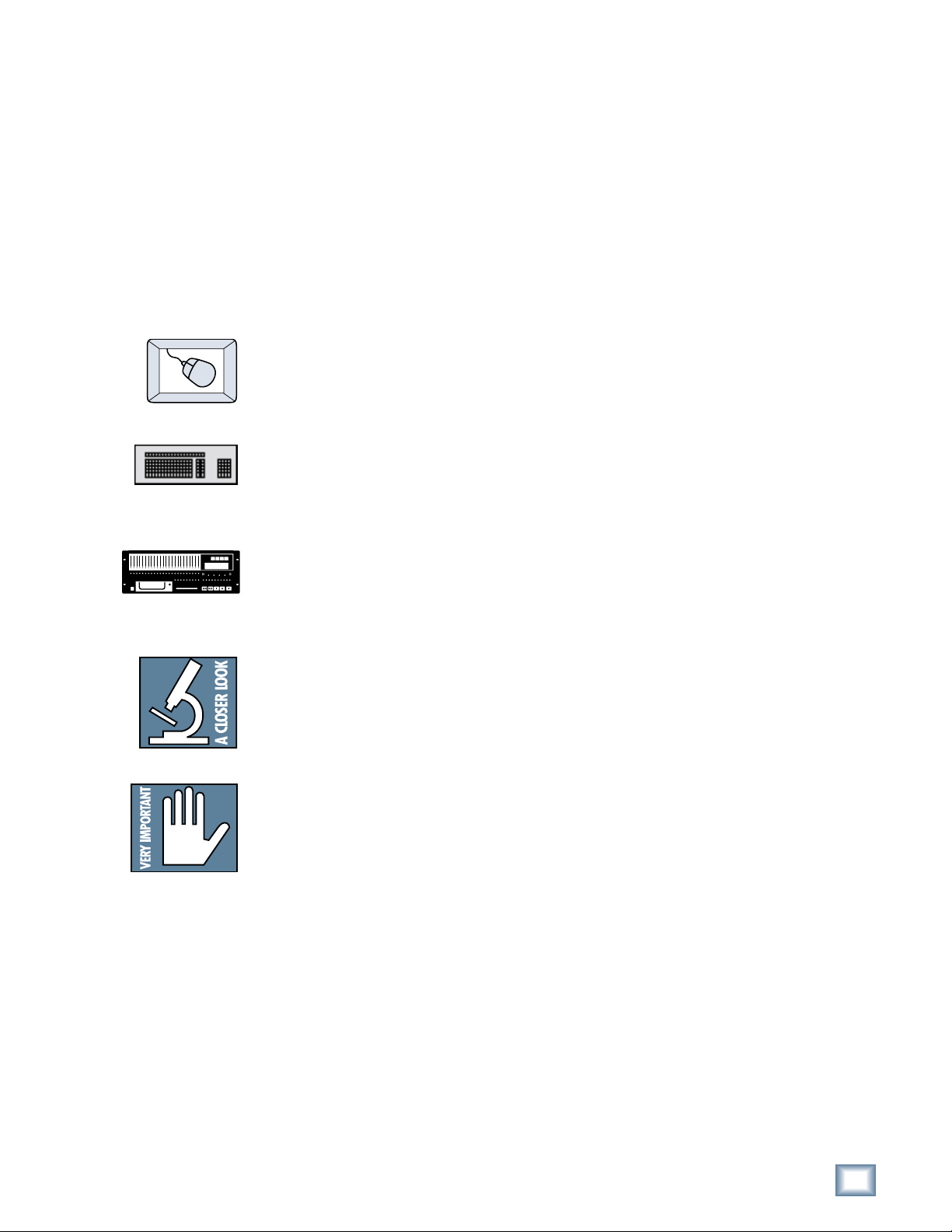
Icons
This icon identifies a description of how to perform an action with the mouse.
This icon identifies a description of how to perform an action with the keyboard.
Operation Guide
This icon identifies a description of how to perform an action from the front panel.
This icon identifies in-depth explanations of features and practical tips. Though
not required reading, they do offer some choice tidbits of knowledge that will
leave you wiser for the reading.
This icon identifies information that is critically important to the operation of the
HDR24/96. So for your own sake, please read these sections.
About “Tape”
No, you’re not reading the wrong manual. Our goal was to build a hard disk
recorder that is comfortable for someone familiar with tape recording, but that
doesn’t require you to get a brain transplant from a computer geek to use. When
familiar terms such as Tape Inputs, Tape Returns, Transport, and the like are
applied to the HDR24/96, they mean exactly what you expect them to mean.
Where the well-worn shoe fits, we continue to wear it.
Operation Guide
5
Page 6
HDR 24/96
Overview
By combining traditional multitrack tape recording features with the power and
flexibility of graphical non-linear editing, the Mackie Designs HDR24/96 takes
multitrack recording to a level never before achieved by a product in its price
range. In addition to the standard battery of traditional tape-based features, the
HDR24/96:
• Combines the familiarity of a multitrack tape machine with the security of
non-destructive recording and non-degrading recording media.
• Includes a Graphical User Interface and a built-in DAW-style editor,
accessible by adding an SVGA monitor, two-button PS/2 compatible
mouse, and a standard PC keyboard.
• Records simultaneously on all 24 tracks at 44.1 or 48 kHz and on 12
tracks at 88.2 or 96 kHz. At 48 kHz the internal hard drive stores over
2200 track-minutes of 24-bit audio (90 minutes of 24 full tracks). That’s
more than six reels of 2” tape at 30 inches per second! At 96 kHz the drive
stores 1100 track-minutes of 24-bit audio (90 minutes of 12 full tracks).
• Has eight Virtual Takes per track, allowing you to record multiple passes
without having to change routing and busing assignments or use
additional tracks.
• Interfaces with any analog or digital console. The HDR24/96 uses the
same I/O cards as the Mackie Digital 8•Bus console: the AIO•8 (24-bit
analog A/D and D/A), DIO•8 (TDIF/ADAT Optical), PDI•8 (AES/EBU),
and low-cost OPT•8 (ADAT Optical).
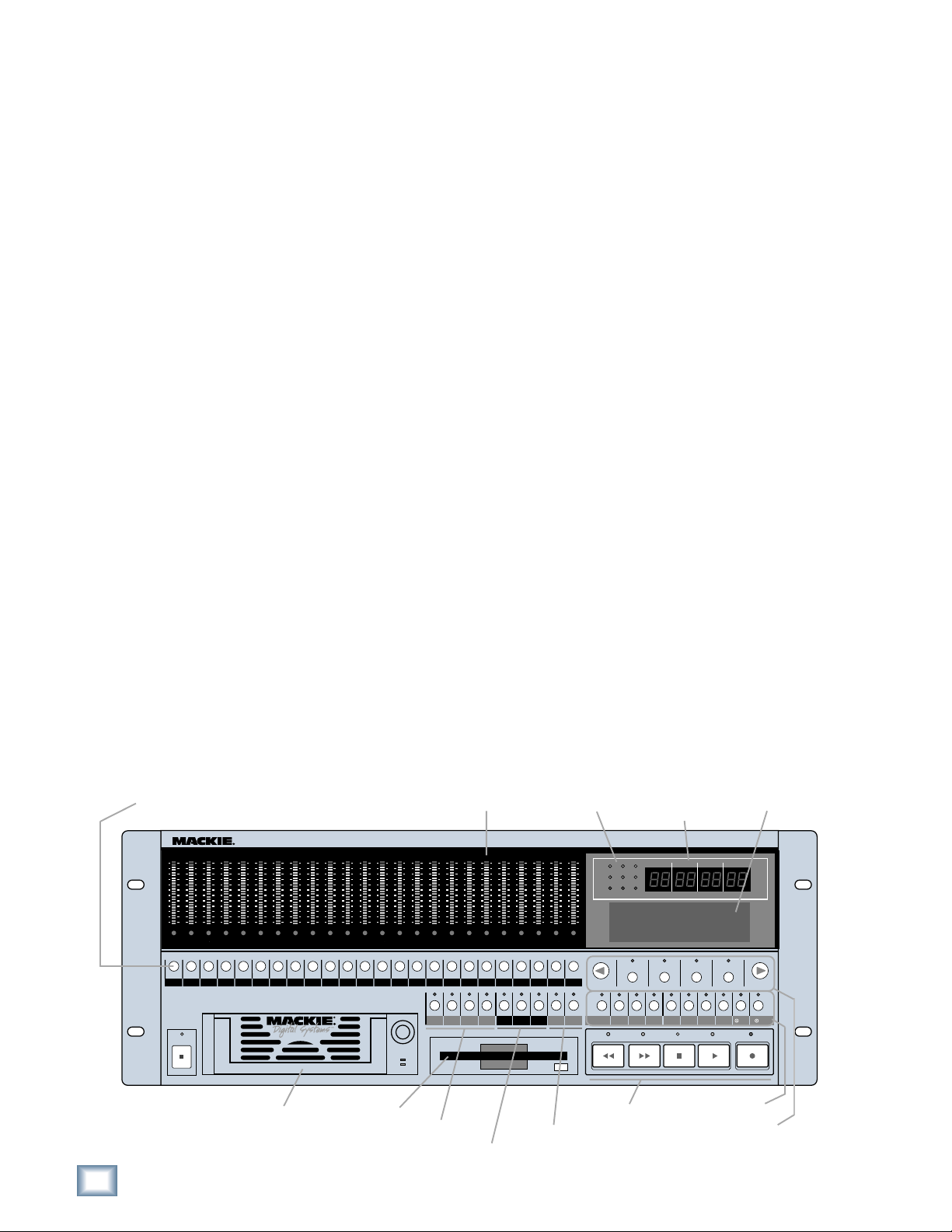
Record Ready
24TRACK/24BIT DIGITAL AUDIO HARD DISK RECORDER/EDITOR
OL
OL
OL
OL
OL
2
2
2
4
4
4
7
7
7
10
10
10
15
15
15
20
20
20
25
25
25
30
30
30
35
35
35
40
40
40
50
50
50
REC REC REC REC REC REC REC REC REC REC REC
POWER
ON
OL
2
2
2
4
4
4
7
7
7
10
10
10
15
15
15
20
20
20
25
25
25
30
30
30
35
35
35
40
40
40
50
50
50
• Provides three convenient methods of backup: Mackie Media M•90, a
removable hard drive (also capable of 24-track recording and playback),
Mackie Media PROJECT, a removable drive using inexpensive, removable
2.2 GB ORB cartridges, and data transfer to another computer through the
HDR24/96’s 100 Base-T Ethernet port via the built-in FTP server.
• Offers two optional remote control devices — the compact Remote 24 for
smaller project studios, and the full-featured Remote 48 for controlling up
to 48 tracks on two HDR24/96 recorders.
Meter Display
OL
OL
OL
OL
OL
OL
OL
OL
OL
OL
OL
OL
2
2
2
2
2
2
2
2
2
4
4
4
4
4
4
7
7
7
10
15
20
25
30
35
40
50
7
10
10
10
15
15
15
20
20
20
25
25
25
30
30
30
35
35
35
40
40
40
50
50
50
4
7
7
7
10
10
10
15
15
15
20
20
20
25
25
25
30
30
30
35
35
35
40
40
40
50
50
50
REC
REC REC REC REC REC REC REC REC REC REC REC REC
2
4
4
4
7
7
7
10
10
10
15
15
15
20
20
20
25
25
25
30
30
30
35
35
35
40
40
40
50
50
50
2
4
7
10
15
20
25
30
35
40
50
LOC 2LOC 1 STORE
OL
2
2
4
4
7
7
10
10
15
15
20
20
25
25
30
30
35
35
40
40
50
50
LOOP
1–2
OL
OL
2
2
4
4
7
7
10
10
15
15
20
20
25
25
30
30
35
35
40
40
50
50
2019181716151413121110987654321
21
ALL
REC
INPUT
SAFE
Status Display
OL
OL
2
2
4
4
7
7
10
10
15
15
20
20
25
25
30
30
35
35
40
40
50
50
242322212019181716151413121110987654321
242322
AUTO
T-CODE
AUTO
TAKE
CHASE
INPUT
Current
Time Display
HDR 24/
44.1k
48k
96k
VARI
24 BIT
16 BIT
ERROR
TC CLOCK
PROJECT: Little love
PLAYLIST: Playlist 1
DRIVE: C:Internal
AVAIL: 01:35:00
TRACKDELETE LAST PROJECT BACKUP DISK UTIL SYSTEM DIGI-I/O SYNC DEC INC
REWIND
FAST FWD
HIGH RESOLUTION AUDIO
96
44.1/48/96K SAMPLE RATES
MINUTESHOURS
BARS
SELECTSELECTSELECT
STOP
SECONDS FR AMES
BEATS
TICKS
SELECT
PLAY
LCD Display
RECORD
Media Tray Floppy Drive
Locate & Loop
Monitoring &
Record Safe
6
HDR 24/96
Auto Take & Time
code Chase
Transport
System Control
LCD Control
Page 7

Setup & Configuration
This chapter explains how to set up and configure the HDR24/96 for use in your
studio. Two application examples show how to interface the HDR24/96 with
analog and digital recording consoles.
Required Equipment
Of course, there’s more to a studio than a recorder and some musicians. At a
minimum, you’ll need the following to make the HDR24/96 feel at home:
• Three Mackie 8-channel I/O (input/output) cards.
• A console with a minimum of 24 tape sends (buses or direct outputs) and
returns (line inputs or monitor returns). If your analog console has only 8
tape sends, use Y-cord splitters to send tape out 1 to HDR24/96 Inputs 1,
9 and 17; tape out 2 to HDR24/96 Inputs 2, 10, and 18, and so forth.
• Cables to connect the HDR24/96 to the console: 3 or 6 multi-channel
snakes or fiber optic cables, depending on your I/O setup.
• All the stuff that typically connects to a console: microphones,
instruments, outboard equipment, control room monitors, and so on.
• Optional, but strongly recommended: an SVGA monitor, two-button PS/2
mouse, and PC keyboard for the Graphical User Interface.
Operation Guide
Installation
This section describes how to install the I/O cards and how to connect the
HDR24/96 to your console. Before you begin, you should choose a location for
your HDR24/96 considering the following:
• If you’re not using the GUI interface, Remote 24, or Remote 48, position
the front panel within convenient reach of your normal recording/mixing
position. If you are using the GUI interface, you might want to get the
HDR24/96 out of the way. Be aware that although analog and AES/EBU
cables can be fairly long, TDIF and Remote 24/Remote 48 cables are
limited to about 10 meters. ADAT Optical and KVM (keyboard, video and
mouse) cables can reach up to about 15 meters.
• The HDR24/96 requires a reliable AC power source with a good ground.
Do not use a ground lift adapter or plug the HDR24/96 into an ungrounded
receptacle. Remember, this is a computer. Using an uninterruptible power
supply (UPS) to power the HDR24/96 is a good idea to avoid an
unexpected shutdown and protect it from transient line voltages.
Warning!
Before applying power to the HDR24/96, make sure that the Voltage Selector
switch next to the AC inlet jack on the rear panel is set to the line voltage used
in your region. Powering-on the HDR24/96 with the Voltage Selector switch
set incorrectly will cause an electrical and fire hazard that may result in
irreparable damage to the unit.
Operation Guide
7
Page 8

HDR 24/96
ANALOG I/O
AIO•8
APOGEE
DIGITAL I/O
I/O Cards & Cables
I/O cards are available in four different flavors and can be mixed and matched in
any combination:
AIO•8
• Each AIO•8 provides 8 analog line-level inputs and outputs on two 25-pin
D-subminiature (DB25) connectors. These connectors are pin-for-pin
compatible with the analog (not TDIF) DB25 connectors found on the
DIO•8
TASCAM DTRS recorders. DB25 cables that break out to XLR or 1/4" TRS
connectors for mating with your console are readily available.
OPT•8
INPUT OUTPUT
PDI• 8
ADAT OPTICAL
PDI•8
TDIF
IN OUT
SYNC
AES/EBU I/O
DIO•8
• Each DIO•8 provides 8 digital inputs and outputs in two formats:
1. TASCAM Digital Interface (TDIF) provides 8 input and output channels
of digital audio on a single DB25 connector. It requires a TASCAM
PW-88D or equivalent TDIF-compatible cable.
2. ADAT Optical provides 8 channels of digital audio on fiber-optic cable.
Two optical cables are required for each card, one for inputs, the other
for outputs. Both cables must connect to the same device, creating a
closed loop.
3. The DIO•8 also provides a TDIF word clock sync output for use with
older TASCAM equipment.
OPT• 8
• The OPT•8 is a low-cost, ADAT Optical-only version of the DIO•8 card.
The previous ADAT information also applies to this card.
PDI• 8
• Each PDI•8 carries four stereo pairs (eight channels) of digital input and
output on a single DB25 connector. This card supports the AES/EBU
(IEC-958 Type 1) digital interfacing standard carrying two channels of
digital audio on a single balanced cable. The PDI•8 can also be configured
for the consumer (IEC-958 Type 2, or S/PDIF) data format if required.
DB25 cables that break out to XLR connectors, and double-ended DB25 to
DB25 AES/EBU cables for mating with your console, are readily available.
The PDI•8 is the only Mackie I/O card that currently supports 88.2 or 96
kHz operation. At these Sample Rates the PDI•8 card runs in “doublewide” (dual-wire) mode. In double-wide mode, the PDI•8 carries four mono
channels of digital I/O by transmitting two consecutive 88.2/96k samples
of the same channel on a single conductor.
Note: Different manufacturers use different wiring standards for DB25 interface cables (both analog and digital) that otherwise look the same. Make
sure the cable you are using is the correct one. See Appendix A for a list of
compatible I/O card cables for the HDR24/96.
8
HDR 24/96
Page 9

To install the I/O cards:
1. If the HDR24/96 is plugged into AC power, unplug it.
2. Remove the I/O card slot cover plates by removing the rather tight top
and bottom screws with a screwdriver.
3. Before you take I/O cards from their bags, touch a grounded metal object
to discharge any static electricity from your body.
Operation Guide
4. Remove the I/O card from its bag and hold it so that the component side
faces left.
5. Line up the card so that the top and bottom
edges slide smoothly into the white card
guides. Push the card all the way in until its
faceplate is flush with the back panel.
6. Hand-tighten the thumbscrews at the top
and bottom of the card. Do not use a
screwdriver.
If you want to hook up the HDR24/96 I/O cables
to your console right now, see the console hookup
diagrams in “Hookups” (page 21). Be sure to come
right back here when you’re done.
Note:Note:
Note: Always hand tighten the thumbscrews
Note:Note:
at the top and bottom of all I/O cards before operating the HDR 24/96.
Operation Guide
9
Page 10

SMPTE Input/
Output
HDR 24/96
Termination
Switch
Word Clock/
Video Input
Word Clock
Output
Sync Card & Cables - Word Clock and Digital Synchronization
The Sync Card provides ports to synchronize the HDR24/96’s sample clock and
time/transport position to other equipment. The functions of the jacks and switch,
from top to bottom are:
• SMPTE Input/Output — This 1/4" TRS jack serves as an input when
slaved to incoming SMPTE time code, and as an output when generating
SMPTE time code to synchronize other devices with the HDR24/96.
• Termination Switch — This pushbutton switch selects the termination
impedance of the Word Clock / Video Input jack. When the switch is out,
the impedance is 3.3kΩ (bridging); when in, the impedance is 75Ω
(terminated).
• Word Clock/Video Input — This BNC jack receives either word clock,
composite video, or video blackburst as determined by the HDR24/96
SYNC
Whenever digital audio connections are made between devices, the sample clock
of every device must run at exactly the same rate. This is usually accomplished by
selecting one device as the “master” clock source and distributing its word clock
signal to all the “slave” devices in the system. The master is configured to run
from its internal clock, and the slaves from external word clock. Some digital
interfaces are self-clocking (such as the AES input on many DAT machines) and
do not require a separate work clock connection. Others simply cannot be
configured as slaves. The master/slave designation must be correctly made for
each device to avoid the clicks and pops associated with asynchronous clocks.
Sample Clock setting. Use this input when the HDR24/96 is operating as a
word clock slave.
• Word Clock Output — This BNC jack transmits word clock to other devices
in the system when the HDR24/96 is configured as word clock master.
Whenever time code (positional) synchronization is used, all the devices in a
system, both analog and digital, must be synchronized to a common timing (speed)
reference. This is often achieved by distributing video from a master video sync
generator (sometimes called “house sync”) to all the slave devices in the system
when word clock cannot otherwise be used. The HDR24/96, like many other
digital devices, can synchronize its sample clock to a video signal. However, video
does not provide enough timing precision to properly synchronize devices whose
digital audio paths are interconnected; word clock must be used instead.
Generally it doesn’t matter which device in a system serves as the word clock
master, except when synchronizing to time code or video. For example, if your
HDR24/96 Inputs and Outputs are connected to the Tape Inputs and Outputs of a
Mackie Digital 8
word clock master. However, if you later synchronize the HDR24/96 to time code
from a VTR, you must lock the VTR and HDR24/96 to a master video sync source
and lock the D8B (which can’t sync to video) to word clock from the HDR24/96. In
this case the HDR24/96 becomes both a video slave and a word clock master. For
more detailed information on setups involving video and time code
synchronization, see the Technical Reference Guide.
Note: Note:
Note: For audio-for-video applications, the HDR24/96 can lock its word clock to
Note: Note:
•Bus console using TDIF, either the HDR24/96 or D8B can be the
a video signal. In this configuration, there must be only one word clock dependent device (the HDR24/96) locked to the video source. The HDR24/96 then
becomes the word clock master for the other digital devices in the system (for
example, a digital mixing console). Do not attempt to lock multiple digital devices to the video signal, or you’ll get clicks.
10
HDR 24/96
Page 11

The following are recommended setups for establishing proper sample clock
synchronization with the devices connected to the HDR24/96 digital I/O cards.
TDIF (DIO•8)
With the HDR24/96 as a master, connect Word Clock Out of the HDR24/96 to
Word Clock In on the receiving device(s). If connecting to older TASCAM
DTRS recorders, use the Sync Out port on the first DIO
Word Clock Out. If there is more than one DTRS recorder in the chain,
connect Sync Out to the word clock input of the first DTRS recorder only; the
other recorders are synchronized through their interconnecting DTRS cables.
With the HDR24/96 operating as a slave to another TDIF device, connect the
word clock output from the master TDIF device to Word Clock In on the
HDR24/96.
•8 card instead of
ADAT Optical (DIO•8, OPT•8)
With the HDR24/96 as a master, set the receiving device(s) to derive sample
clock from their ADAT Optical ports if the ports are self-clocking. In this
case, no word clock connection is necessary. If the ADAT Optical ports on the
receiving devices are not self-clocking, connect Word Clock Out of the
HDR24/96 to Word Clock In on the receiving device(s).
With the HDR24/96 configured as a slave, connect the word clock out of the
master ADAT Optical device to Word Clock In on the HDR24/96.
Operation Guide
AES/EBU (PDI•8)
With the HDR24/96 as a master, set the receiving device(s) to derive their
sample clock from the AES/EBU ports if the ports are self-clocking. In this
instance, no word clock connection is necessary. If the AES/EBU ports on the
receiving device(s) are not self-clocking, connect Word Clock Out of the
HDR24/96 to Word Clock In of the receiving device(s).
With the HDR24/96 as a slave, connect the word clock out of the master
AES/EBU device to Word Clock In on the HDR24/96.
Note:Note:
Note: Use 75 Ω coaxial cables when con-
Note:Note:
necting word clock or video to the Sync
Card Word Clock/Video input jack. If the
Termination
Switch
Word Clock to
other Slaves
HDR24/96 is at the end of a cable that’s
connected to several devices, push the
Termination Switch in; otherwise leave it
Word Clock
Input jack
out and use a BNC Tee adapter to feed the
signal on to the next device in the chain.
Note:Note:
Note: If you are using an HDR24/96 with the Mackie Digital
Note:Note:
SYNC
Word Clock
From Master
8•Bus console, you may need to turn on the Digital 8•Bus first.
The Clock I/O on the D8B prefers not to see an active signal at
its Word Clock input when it powers up.
BNC-Tee
adaptor
Operation Guide
11
Page 12

HDR 24/96
Mackie Media (Optional)
The HDR24/96 emulates the tape library tradition with Mackie Media M•90 and
Mackie Media PROJECT drives. Both drives come complete with a plug-in tray for
quick removal and a nifty storage case for shelving and transporting the drives.
Trays can be purchased separately if you want to use your own UDMA IDE drives.
The HDR24/96 can record or play directly off the M
sessions as quickly as changing tape on a 24-track — no backup time required.
PROJECT drives are for backup only and use removable 2.2GB ORB cartridges that
fit in your pocket. Each can hold two or three 5-minute 24-track masters.
Blank Plate
Mackie Media
Receiver
To install or remove a Mackie Media tray:
1. Power the HDR24/96 off. Don’t forget to save your project first!
•90, so you can change
24TRACK/24BIT DIGITAL AUDIO HARD DISK RECORDER/EDITOR
OL
OL
OL
OL
OL
OL
OL
OL
OL
OL
OL
OL
OL
OL
OL
OL
OL
2
2
2
2
2
2
2
2
4
4
4
4
4
4
4
4
7
7
7
7
7
7
7
7
10
10
10
10
10
10
10
10
15
15
15
15
15
15
15
15
20
20
20
20
20
20
20
20
25
25
25
25
25
25
25
25
30
30
30
30
30
30
30
30
35
35
35
35
35
35
35
35
40
40
40
40
40
40
40
40
50
50
50
50
50
50
50
50
REC REC REC REC REC REC REC REC REC REC REC
POWER
ON
2
2
4
4
7
7
10
10
15
15
20
20
25
25
30
30
35
35
40
40
50
50
OL
2
2
2
2
2
2
2
2
4
4
4
4
4
4
4
4
7
7
7
7
7
7
7
7
10
10
10
10
10
10
10
10
15
15
15
15
15
15
15
15
20
20
20
20
20
20
20
20
25
25
25
25
25
25
25
25
30
30
30
30
30
30
30
30
35
35
35
35
35
35
35
35
40
40
40
40
40
40
40
40
50
50
50
50
50
50
50
50
REC
REC REC REC REC REC REC REC REC REC REC REC REC
LOOP
LOC 2LOC 1 STORE
1–2
OL
OL
2
2
4
4
7
7
10
10
15
15
20
20
25
25
30
30
35
35
40
40
50
50
ALL
REC
INPUT
SAFE
OL
OL
OL
2
2
2
4
4
4
7
7
7
10
10
10
15
15
15
20
20
20
25
25
25
30
30
30
35
35
35
40
40
40
50
50
50
242322212019181716151413121110987654321
242322212019181716151413121110987654321
AUTO
T-CODE
AUTO
TAKE
CHASE
INPUT
HIGH RESOLUTION AUDIO
HDR 24/
96
44.1/48/96K SAMPLE RATES
MINUTESHOURS
SECONDS FRAMES
44.1k
48k
96k
VARI
24 BIT
16 BIT
ERROR
TC CLOCK
BEATS
BARS
PROJECT: Little love
PLAYLIST: Playlist 1
DRIVE: C:Internal
AVAIL: 01:35:00
REWIND
TICKS
SELECT
SELECTSELECTSELECT
TRACKDELETE LAST PROJECT BACKUP DISK UTIL SYSTEM DIGI-I/O SYNC DEC INC
PLAY
FAST FWD
STOP
RECORD
2. To install a new M•90 or PROJECT drive, first remove the blank plate by
inserting the key and turning it a quarter-turn counterclockwise. Pull out
from the edge of the plate closest to the key to remove it. Slide the media
tray into the front panel drive bay. Press it firmly into place, and latch it by
pressing the bail handle downward until it’s fully seated.
3. Insert the key into the lock and turn it a quarter-turn clockwise. The key
locks the drive into place and powers the tray.
4. The HDR24/96 automatically detects the Mackie Media drive when you
power it up again.
5. To remove a drive, first unlock it by inserting the key and turning it a
quarter-turn counterclockwise. Two keys are packed with the recorder, and
one with each M•90 drive.
6. Lift the bail handle to release the drive, and pull it out of the drive bay.
Note: Note:
Note: Mackie Media are hard drives, and as we all know, hard drives
Note: Note:
involve some pretty intricate technology. So don’t shake the little
darlin’, and if a tray has just come in from a freezing car or airplane
cargo hold, do not install it until it has reached room temperature.
12
HDR 24/96
Page 13

Monitor / Mouse / Keyboard (Optional)
Most of the HDR24/96 editing features require a monitor, mouse and keyboard.
Here’s how to install them:
1. Connect a color SVGA monitor to the HDR24/96 Video connector. The
monitor should support a 1024x768 screen resolution at a 60 Hz vertical
scan rate, and for the best picture, should have at least a 17" screen.
2. Connect a two-button PS/2 compatible mouse to the Mouse port.
3. Connect a PC-style keyboard to the Keyboard port. If your keyboard has a
PS/2 style connector, you will also need a male 5-pin DIN to female PS/2
adapter, readily available at any computer store.
No special software configuration is required for these devices. On bootup, the
HDR24/96 will automatically detect their presence and configure itself
accordingly.
Operation Guide
Keyboard
Mouse
Video
Operation Guide
13
Page 14

Note:Note:
Note: The Remotes
Note:Note:
duplicate nearly all of
the front panel oper-
ating controls and
HDR 24/96
some extras to boot.
When we describe a
front panel operation,
you’ll probably find it
available on the Re-
mote also.
Remote 24 / Remote 48 (Optional)
Installing either remote is as simple as plugging in a telephone. Connect one end
of the cable (supplied with the Remote) to the ‘REMOTE’ jack on HDR24/96 rear
panel, and the other end to the ‘TO HDR REMOTE JACK’ jack on the Remote 24,
or to the “TO HDR” jack on the Remote 48. It’s OK to plug or unplug either
Remote with the HDR24/96 powered on. However, if you plug the Remote 48 into
the HDR24/96 while both are powered on, you must power cycle the Remote 48 to
reset the connection.
REMOTE 24
Remote
connection
WARNING
DO NOT PLUG INTO
ETHERNET
TO HDR
REMOTE JACK
FOOT SW
Note:Note:
Note: The HDR24/96 ‘REMOTE’ and
Note:Note:
Ethernet jacks both accept CAT-5 Ethernet
cables - don’t get them mixed up!
Back panel of the
Mackie Remote 24
Footswitch
Note:Note:
Note: If you are us-
Note:Note:
ing an HDR24/96
with the Mackie Digi-
tal 8•Bus console,
you may need to turn
on the Digital 8•Bus
first. The Clock I/O
on the D8B prefers
not to see an active
signal at its Word
Clock input when it
powers up.
Footswitch
Ethernet Jack
Footswitch (Optional)
For hands-free do-it-yourself punches and other frequently-used functions like
Play/Stop, New Cue, Solo, and Next Cue, connect the cable of a momentary,
normally open footswitch to the ‘FOOT SWITCH’ 1/4" TS jack on the rear panel of
the HDR24/96, the Remote 24, or Remote 48. If you have a Remote installed you
can connect two foot switches, one to the HDR24/96 and one to the Remote. Each
footswitch functions independently of the other. Footswitch functionality is
assigned in the front panel System menu or the GUI General Setup window. See
the Technical Reference Guide for more details.
Power-Up
OK, NOW you can turn it on. Assuming you have already connected the HDR24/96
to your console, power up the HDR24/96 first, then the outboard equipment and
console, and finally the power amplifiers or powered monitors. Audio equipment
tends to generate unexpected clicks and pops when you power it up, so by
powering up your monitoring system last, you’ll save your speakers and your ears.
Before you read the next section, take a quick, self-guided tour of the front panel
display and controls to get a sense of where they are.
14
HDR 24/96
Page 15

Configuration
Before starting a Project, you need to configure the HDR24/96 I/O card options
and synchronization parameters. These parameters determine where the sample
clock is coming from, how fast the sample clock runs, and how many bits are
recorded in every sample. Some options, like sample rate and bit depth, will
become “standards” that you won’t need to change very often. The remaining
synchronization options (for time code and video) are covered in detail in the
Technical Reference Guide.
I/O Cards
Only the DIO•8 and PDI•8 cards require special configuration. If you are using
AIO•8 or OPT•8 cards only, you can skip to the next section.
DIO•8 Card
To set the DIO•8 input and output formats:
Operation Guide
Note:Note:
Note: The front panel
Note:Note:
display’s backlight
switches off after ten
minutes of inactivity.
It’ll come back on auto-
matically when it’s
needed to display new
information, but you
can revive it at any time
by pressing either the
Page Left [<] or Page
Right [>] button below
the display.
1. Press DIGI-I/O to enter
the Digital I/O Card Setup
menu.
2. Select In.
The Setup Tape Inputs screen shows
you the current input settings for
each of the three I/O cards.
3. Press the Select button
corresponding to each DIO•8 card
and toggle the selection between ADAT and TDIF.
4. Press the Page Left (<) button to return to the previous screen.
5. Now select Out.
The Setup Tape Outputs screen
shows you the current output
settings for each of the three I/O
cards.
6. For each DIO•8 card present,
press the Select button to select the desired output format. Or, select
the TD–>AD or AD–>TD option to convert between formats, bypassing
the HDR24/96 tape signal path entirely.
DIGI-I/O
DIGITAL I/O Card Setup
Stat Rate
In Out Bits Convert
(SETUP TAPE INPUTS)
1-8 9-16 17-24
ADAT ADAT ADAT
(SETUP TAPE OUTPUTS)
1-8 9-16 17-24
ADAT ADAT ADAT
7. When done, press DIGI-I/O to exit the menu.
Operation Guide
15
Page 16

HDR 24/96
1. Select Setup from the Windows menu (or use
keyboard shortcut CTRL+1) and click the
Digital I/O icon.
The Digital I/O Setup dialog shows you the current
settings for each of the three I/O cards (see
illustration below).
2. Click the Input pulldown menu and select either
ADAT or TDIF for each DIO•8 card.
3. Click the Output pulldown menu and select the
desired output format. Or, select the TDIF–>ADAT or ADAT–>TDIF
option to convert between formats, bypassing the HDR24/96 tape signal
path entirely.
4. Click the arrow in the top right corner of the dialog or hit ESC to exit.
I/O Card 1-8
(AIO•8)
AIO-8
I/O Card 9-16
(DIO•8)
DIO-8
ADAT
ADAT
ADAT
TDIF
TD -> AD
AD -> TD
I/O Card 1724 (PDI•8)
PDI-8
Setup
The input and output settings on the DIO•8 card need not be the same.
For example, you can use outboard A/D converters with ADAT Optical
outputs and a console with TDIF inputs without problems. Just remember
to correctly set up Word Clock.
16
HDR 24/96
Page 17

PDI•8 Card
The PDI•8 card options include sample rate conversion for each stereo AES/EBU
input, and status bit control (pro/consumer mode) for each output. When a PDI•8
card is first installed, its default settings are for sample rate conversion Off, and
channel status bits set to indicate the Pro (AES/EBU) format. In most
circumstances you won’t need to change these settings. However, if the device(s)
connected to the PDI•8 inputs cannot be made a clock master or slave (such as a
CD player with a digital out), enabling sample rate conversion on each affected
input will effectively re-clock the incoming data.
Occasionally you’ll run across a device that will not recognize the digital audio
output from the PDI•8 card. Changing the status bits on the affected output(s)
from Pro to Consumer (S/PDIF) may solve the problem.
Remember that with the AES/EBU format, channels come in pairs, so rather than
eight settings, you have four, one for each pair of channels.
To set the PDI•8 card options:
DIGITAL I/O Card Setup
1. Press DIGI-I/O to enter
the Digital I/O Card Setup
menu.
2. Select Rate Convert. The
Sample Rate Convert screen shows
you the Sample Rate Conversion
settings for inputs 1-8.
DIGI-I/O
Stat Rate
In Out Bits Convert
SAMPLE RATE CONVERT ->
1-2 3-4 5-6 7-8
ON OFF OFF ON
3. Press the Select button
corresponding to the desired input channel(s) and toggle the selection.
On enables sample rate conversion, Off disables it (default).
Operation Guide
4. Press the Page Right (>) button to scroll to channels 9-16. Repeat the
procedure for channels 9-16 and 17-24. Press Page Left (<) until you
return to the Digital I/O Card Setup screen.
5. Select Stat Bits. The Setup Status
Bits screen shows you the current
Status Bit settings for outputs 1-8.
SETUP STATUS BITS
1-2 3-4 5-6 7-8
6. Press the Select button
corresponding to the desired output
channel(s) to toggle the selection between Pro (default) and Consu.
7. Press the Page Right (>) button to scroll to channels 9-16. Repeat the
procedure for channels 9-16 and 17-24. Press DIGI-I/O to exit.
Pro Pro Pro Consu
Operation Guide
17
Page 18

1. Select Setup from the Windows menu (or use
keyboard shortcut CTRL+1).
2. Click the Digital I/O icon. For each PDI•8 card,
click the Setup button. In the AES/EBU Setup
dialog, check the Converted boxes corresponding
to the desired input(s) to enable sample rate
conversion; leave the boxes unchecked for no
sample rate conversion (default).
HDR 24/96
3. Then select Pro (default) or Consumer from the
pulldown menus associated with the desired
output(s). Click the arrow in the top right corner of
the dialog or hit ESC to exit.
I/O Card 1724
AIO-8
Note: Note:
Note: When sample rate conversion is active, the input signal is truncated to 20
Note: Note:
DIO-8
ADAT
ADAT
PDI-8
Setup
Setup AES Card - Slot 3
Sample Rate Conversion:
1- 2 Converted
3- 4 Converted
5- 6 Converted
7- 8 Converted
Optimal settings are - NOT converted and Pro.
Stadus Bits:
Pro
Pro
Pro
Pro
Consumer
Pro
bits, causing a slight degradation in the signal quality of a 24-bit input. Therefore
sample rate conversion should be enabled only when intentionally converting a
signal to a different sample rate (e.g., from 44.1k to 48k), or when no other means
exist to establish clock synchronization with the device(s). See the Technical Reference Guide for details.
18
HDR 24/96
 Loading...