


lumen DPP-EX7 Service Manual

DIGITAL PHOTO PRINTER
DPP-EX7
SERVICE MANUAL
Volume 1 1st Edition

! WARNING
This manual is intended for qualified service personnel only.
To reduce the risk of electric shock, fire or injury, do not perform any servicing other than that
contained in the operating instructions unless you are qualified to do so. Refer all servicing to
qualified service personnel.
! WARNUNG
Die Anleitung ist nur für qualifiziertes Fachpersonal bestimmt.
Alle Wartungsarbeiten dürfen nur von qualifiziertem Fachpersonal ausgeführt werden. Um die
Gefahr eines elektrischen Schlages, Feuergefahr und Verletzungen zu vermeiden, sind bei
Wartungsarbeiten strikt die Angaben in der Anleitung zu befolgen. Andere als die angegeben
Wartungsarbeiten dürfen nur von Personen ausgeführt werden, die eine spezielle Befähigung
dazu besitzen.
! AVERTISSEMENT
Ce manual est destiné uniquement aux personnes compétentes en charge de l’entretien. Afin
de réduire les risques de décharge électrique, d’incendie ou de blessure n’effectuer que les
réparations indiquées dans le mode d’emploi à moins d’être qualifié pour en effectuer d’autres .
Pour toute réparation faire appel à une personne compétente uniquement.
WARNING
This unit has no power switch.
When installing the unit, incorporate a readily
accessible disconnect device in the fixed wiring, or
connect the power cord to a socket-outlet which must
be provided near the unit and easily accessible, so that
the user can turn off the power in case a fault should
occur.
WARNUNG
Dieses Gerät hat keinen Netzschalter.
Beim Einbau des Geräts ist daher im Festkabel ein
leicht zugänglicher Unterbrecher einzufügen, oder das
ß
Netzkabel mu
befindlichen, leicht zugänglichen Wandsteckdose
verbunden werden, damit sich bei einer
Funktionsstörung die Stromversorgung zum Gerät
jederzeit unterbrechen läßt.
mit einer in der Nähe des Geräts
DPP-EX7 V1

Table of Contents
Manual Structure
Purpose of this manual .............................................................................................. 3
Related manuals......................................................................................................... 3
1. Service Information
1-1. Main Parts Location ....................................................................................1-1
1-1-1. Main Block Location.................................................................. 1-1
1-1-2. Board Location ...........................................................................1-1
1-2. Removal and Installation of Cabinet...........................................................1-1
1-2-1. Upper Cabinet Assembly ...........................................................1-1
1-2-2. LCD Sub Assembly.................................................................... 1-2
1-3. Sensor Arrangement and Functional Description .......................................1-3
2. Replacement of Main Parts
2-1. Replacement of Board.................................................................................2-1
2-1-1. DK-45 Board ..............................................................................2-1
2-1-2. PW-45 Board..............................................................................2-2
2-1-3. MD-45 Board .............................................................................2-2
2-1-4. JD-45 Board ...............................................................................2-3
2-1-5. PE-45 Board ............................................................................... 2-3
2-1-6. RM-45 Board ............................................................................. 2-4
2-1-7. PR-45 Board ...............................................................................2-4
2-1-8. TP-45 Board ............................................................................... 2-5
2-2. DC Fan ........................................................................................................2-5
2-3. Paper Eject Guide Assembly....................................................................... 2-6
2-4. Mechanical Deck Assembly........................................................................ 2-6
2-5. Switching Regulator....................................................................................2-7
2-6. PCMCIA Ejector .........................................................................................2-7
2-7. Thermal Head..............................................................................................2-8
2-8. Paper Feed Frame Assembly....................................................................... 2-8
2-9. Chassis Assembly........................................................................................2-9
2-10. Stepping Motor............................................................................................2-9
2-11. E Capstan Roller .......................................................................................2-10
2-12. LCD Module .............................................................................................2-11
DPP-EX7 V1
1

3. Service Mode
3-1. Activation ....................................................................................................3-1
3-2. Touch Panel Position Adjustment ...............................................................3-1
3-3. LCD Contrast Check and Adjustment.........................................................3-2
3-4. Density Adjustment for During Thermal Head Replacement.....................3-2
4. Troubleshooting
4-1. Electrical Troubleshooting ..........................................................................4-1
4-2. Error Display ...............................................................................................4-2
4-3. Mechanical Troubleshooting....................................................................... 4-5
4-4. Upgrade .......................................................................................................4-7
2
DPP-EX7 V1

Purpose of this manual
Related manuals
Manual Structure
This manual is the service manual Vol. 1 of Digital Photo Printer DPP-EX7.
This manual describes the information on maintenance and the service information
such as parts replacement, service mode and troubleshooting.
In addition to this “Service Manual Vol. 1”, this unit is provided with the manual
below.
..
. Service Manual Vol. 2 (Not supplied for products.)
..
Part No.: 9-955-392-21
This manual describes the semiconductors, spare parts, block diagrams, schematic
diagrams, and board layouts of this unit.
..
. Operating Instruction (Supplied for products.)
..
Part No.: 3-207-207-11
These manuals describe the information required for the actual management and
operation of this unit.
..
. “Semiconductor Pin Assignments” CD-ROM (Available on request)
..
This “Semiconductor Pin Assignments” CD-ROM allows you to search for
semiconductors used in B&P Company equipment.
Semiconductors that cannot be searched for on this CD-ROM are listed in the
service manual for the corresponding unit. The service manual contains a complete list of all semiconductors and their ID Nos., and thus should be used together
with the CD-ROM.
Part number: 9-968-546-XX
DPP-EX7 V1
3

Section 1
BVTP
3x20
BVTP
3x20
Upper cabinet
assembly
CN201
CN152
DK-45 board
Flexible printed
wiring board
Flexible
flat cable
Service Information
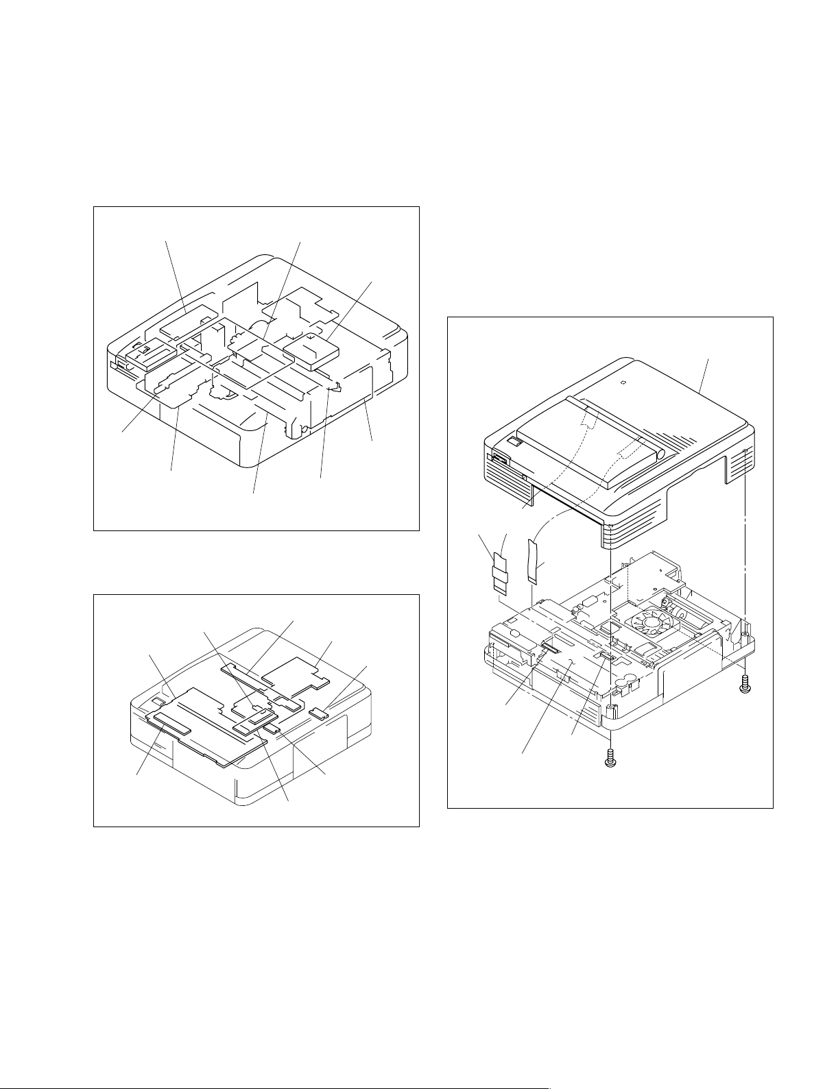
1-1. Main Parts Location
1-1-1. Main Block Location
LCD module
PCMCIA
ejector
Inverter unit
Switching
regulator
Paper feed frame assembly
Thermal head
DC fan
Chassis
assembly
1-2. Removal and Installation of Cabinet
1-2-1. Upper Cabinet Assembly
1. Remove the four screws, then remove the upper
cabinet assembly.
2. Disconnect the flexible printed wiring board and one
flexible flat cable from the connectors (CN152 and
CN201) on the DK-45 board.
1-1-2. Board Location
RM-45 board
DK-45 board
PW-45 board
PR-45 board
MD-45 board
JD-45 board
PE-45 board
TP-45 board
3. Attach the upper cabinet assembly in the reverse order
of steps 1 to 2.
DPP-EX7 V1
1-1
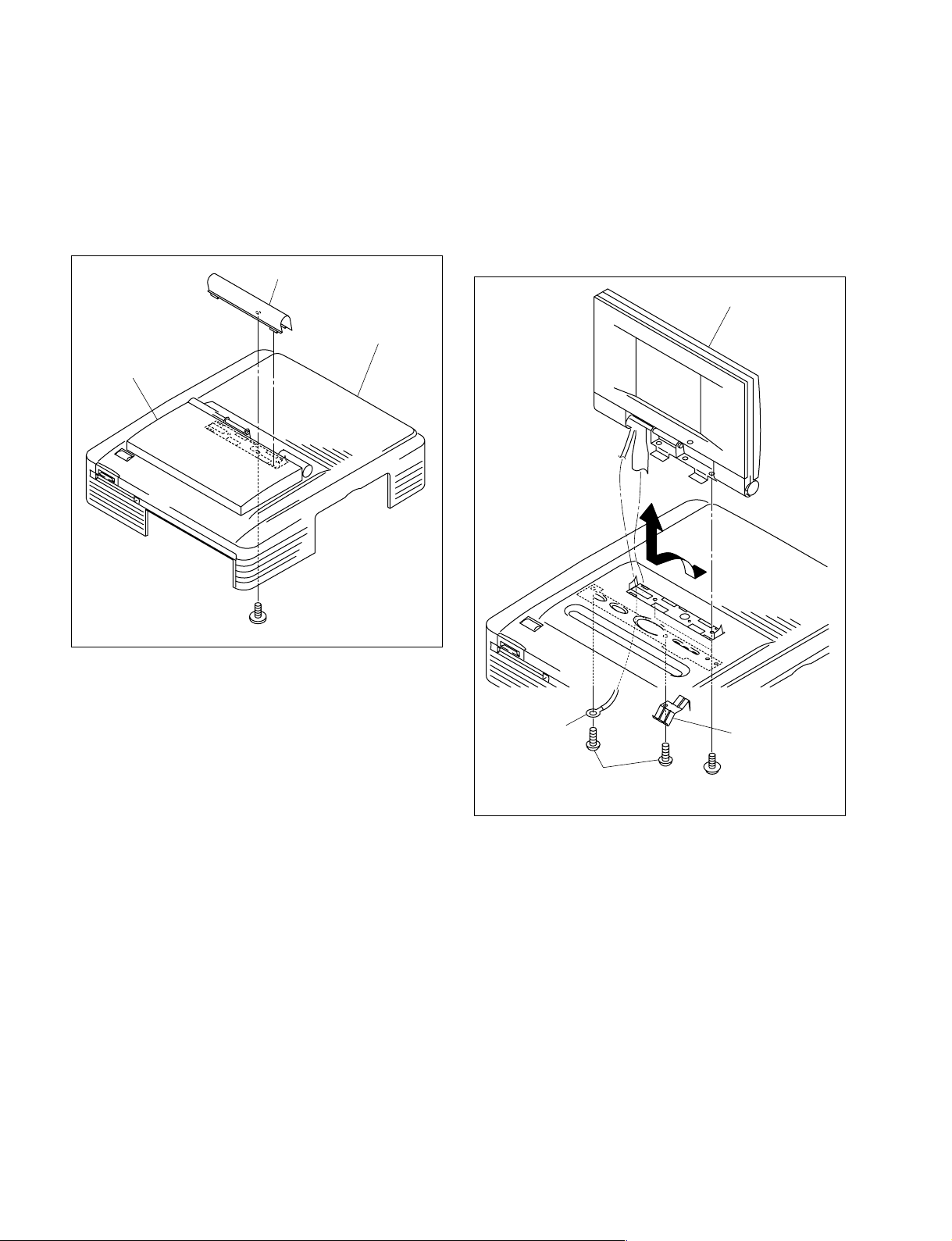
1-2-2. LCD Sub Assembly
1. Remove the upper cabinet assembly. (Refer to Section
1-2-1.)
2. Remove one screw, then remove the hinge cover
assembly.
Hinge cover assembly
Upper cabinet
assembly
LCD sub assembly
3. Remove one screw (BVTP 2.6x6), then remove the
harness.
4. Remove one screw (BVTP 2.6x6), then remove the
spring (PR).
5. Remove two screws (BSW 2.6x8), then remove the
LCD sub assembly in the direction indicated by the
arrow.
LCD sub assembly
PTTWH 2x5
Harness
BVTP
2.6x6
Spring (PR)
PSW
2.6x8
6. Attach the LCD sub assembly in the reverse order of
steps 1 to 5.
1-2
DPP-EX7 V1
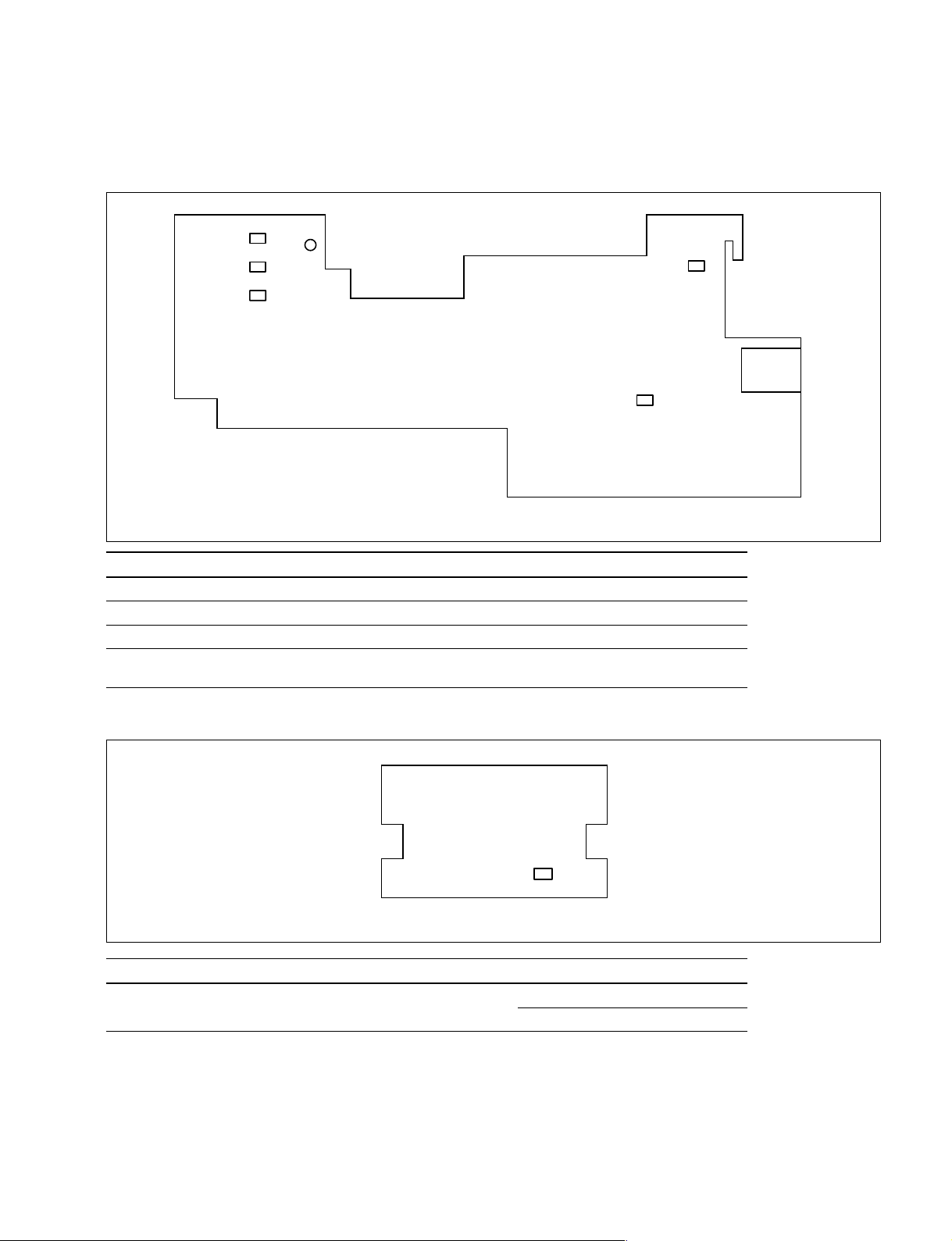
1-3. Sensor Arrangement and Functional Description
MD-45 board
PH901
PH902
PH905
Ref. Name Type Function
PH903, 904 Mode position sensor Reflection type x2 Detects the position of a DC motor.
PH901, 902 Ribbon code sensor Reflection type x2 Detects the type of a ribbon.
D901 Ribbon mark sensor Transmissive type (LED) Detects the mark of each ribbon color.
PH905 Ribbon in-sensor Reflection type x1 Detects the existence of a ribbon
D901
PH903
PH904
MD-45 board (Side A)
cassette.
JD-45 board
PH1020
JD-45 board (Side A)
Ref. Name Type Function
PH1020 Jamming dead sensor Reflection type x1 Detects the paper position.
Detects the paper type.
DPP-EX7 V1
1-3
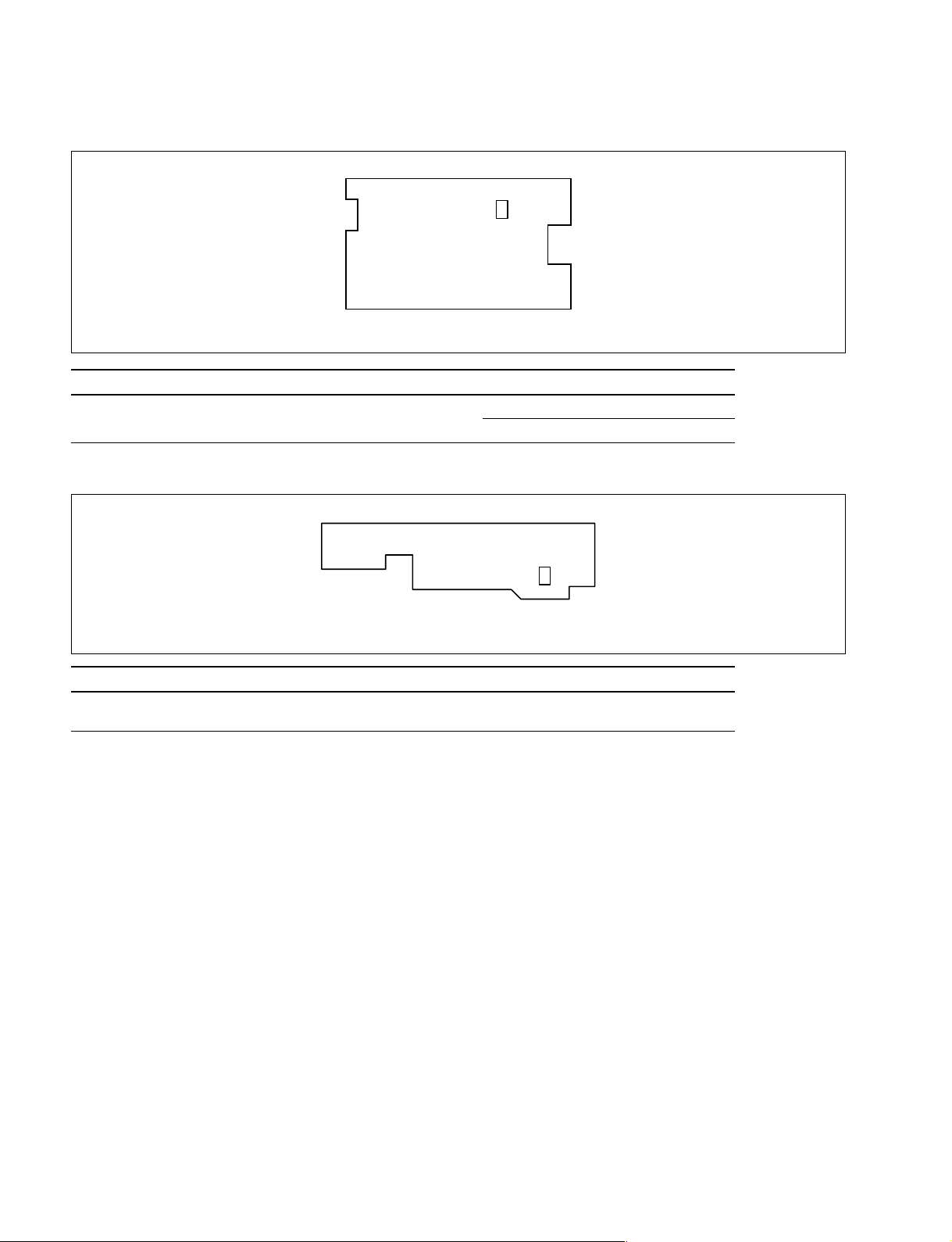
PE-45 board
PH1030
PE-45 board (Side A)
Ref. Name Type Function
PH1030 Paper edge sensor Reflection type x1 Detects the paper position.
Detects the paper type.
RM-45 board
Q1040
RM-45 board (Side A)
Ref. Name Type Function
Q1040 Ribbon mark sensor Transmissive type Detects the mark of each ribbon color.
(photo transistor)
1-4
DPP-EX7 V1
Section 2
Replacement of Main Parts
2-1. Replacement of Board
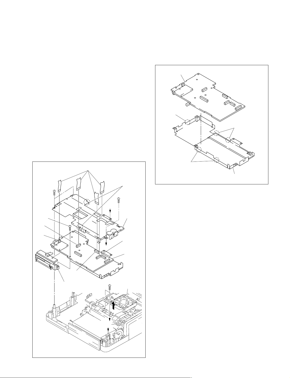
2-1-1. DK-45 Board
1. Remove the upper cabinet assembly. (Refer to Section
1-2-1.)
2. Disconnect the four flexible flat cables from the
connectors (CN251, CN252, CN253 and CN255) on
the DK-45 board.
3. Remove the three screws (BVTP 2.6x8), two screws
(BVTT 2.6x5) and one screw (BTP 2.6x10), then
raise the ferrite holder in the direction indicated by the
arrow and remove the DK-45 board.
4. Remove the PC/MS guide assembly from the DK-45
board.
5. Remove the two solders, then remove the upper DK
shield case from the DK-45 board.
Flexible flat cables
Solders
BVTP
2.6x8
BVTP
2.6x8
6. Remove the five solders, then remove the lower DK
shield case from the DK-45 board.
DK-45 board
Solder
Solders
Solders
Lower DK shield case
7. Install the DK-45 board in the reverse order of steps 1
to 6.
BTP
2.6x10
CN251
CN255
CN253
PC/MS guide
assembly
BVTT
2.6x5
B
A
B
A
Upper DK
shield case
CN252
DK-45 board
Ferrite holder
DPP-EX7 V1
2-1