

Page 1

DIGITAL PHOTO PRINTER
DPP-EX50
SERVICE MANUAL
Volume 1 1st Edition
Page 2
! WARNING
This manual is intended for qualified service personnel only.
To reduce the risk of electric shock, fire or injury, do not perform any servicing other than that
contained in the operating instructions unless you are qualified to do so. Refer all servicing to
qualified service personnel.
! WARNUNG
Die Anleitung ist nur für qualifiziertes Fachpersonal bestimmt.
Alle Wartungsarbeiten dürfen nur von qualifiziertem Fachpersonal ausgeführt werden. Um die
Gefahr eines elektrischen Schlages, Feuergefahr und Verletzungen zu vermeiden, sind bei
Wartungsarbeiten strikt die Angaben in der Anleitung zu befolgen. Andere als die angegeben
Wartungsarbeiten dürfen nur von Personen ausgeführt werden, die eine spezielle Befähigung
dazu besitzen.
! A VERTISSEMENT
Ce manual est destiné uniquement aux personnes compétentes en charge de l’entretien. Afin
de réduire les risques de décharge électrique, d’incendie ou de blessure n’effectuer que les
réparations indiquées dans le mode d’emploi à moins d’être qualifié pour en effectuer d’autres.
Pour toute réparation faire appel à une personne compétente uniquement.
WARNING
This unit has no power switch.
When installing the unit, incorporate a readily
accessible disconnect device in the fixed wiring, or
connect the power cord to a socket-outlet which must be
provided near the unit and easily accessible, so that the
user can turn off the power in case a fault should occur.
WARNUNG
Dieses Gerät hat keinen Netzschalter.
Beim Einbau des Geräts ist daher im Festkabel ein
leicht zugänglicher Unterbrecher einzufügen, oder das
ß
Netzkabel mu
befindlichen, leicht zugänglichen Wandsteckdose
verbunden werden, damit sich bei einer
Funktionsstörung die Stromversorgung zum Gerät
jederzeit unterbrechen lä
mit einer in der Nähe des Geräts
ß
t.
DPP-EX50 V1
Page 3

Table of Contents
Manual Structure
Purpose of this manual .............................................................................................. 3
Related manuals......................................................................................................... 3
Trademarks ................................................................................................................ 3
1. Service Overview
1-1. Main Parts Location ....................................................................................1-1
1-1-1. Main Block Location..................................................................1-1
1-1-2. Board Location...........................................................................1-1
1-1-3. Sensor Location and Function Description ................................1-2
1-2. Removing/Installing the Cabinet................................................................. 1-4
1-2-1. Front Door Assembly................................................................. 1-4
1-2-2. Ribbon Door...............................................................................1-4
1-2-3. Cabinet (L) Assembly ................................................................1-5
1-2-4. FT Panel Assembly ....................................................................1-5
1-2-5. Cabinet (R) Assembly ................................................................1-6
2. Main Parts Replacement
2-1. Replacing the Board....................................................................................2-1
2-1-1. MC-46 Board .............................................................................2-1
2-1-2. SW-46 Board/LCD.....................................................................2-2
2-1-3. DK-46 Board.............................................................................. 2-2
2-1-4. UV-46 Board.............................................................................. 2-3
2-1-5. MD-46 Board .............................................................................2-3
2-1-6. JD-46 Board ...............................................................................2-4
2-1-7. PE-46 Board ...............................................................................2-4
2-1-8. RM-46 Board .............................................................................2-5
2-2. Switching Regulator....................................................................................2-6
2-3. Paper Eject Guide Assembly.......................................................................2-7
2-4. F Chassis Assembly ....................................................................................2-7
2-5. K Frame Assembly......................................................................................2-8
2-6. DC Fan ........................................................................................................2-8
2-7. Thermal Head..............................................................................................2-9
2-8. Ferrite Holder.............................................................................................. 2-9
2-9. Stepping Motor.......................................................................................... 2-10
2-10. E Capstan Roller .......................................................................................2-10
DPP-EX50 V1
1
Page 4

3. Service Mode
3-1. Operation panel ...........................................................................................3-1
3-2. Activation....................................................................................................3-2
3-3. Density Adjustment during Thermal Head Replacement ...........................3-3
3-4. Confirmation and Adjustment of Video Output Level ............................... 3-7
3-5. Operation Check of Key, Fan, LED, LCD and Buzzer...............................3-9
3-6. USB Host and Device Communication Check ......................................... 3-12
3-7. Mechanical Operation Check.................................................................... 3-13
4. Troubleshooting
4-1. Electrical Troubleshooting..........................................................................4-1
4-2. Error Display...............................................................................................4-2
4-3. Upgrade.......................................................................................................4-5
4-3-1. Firmware ....................................................................................4-5
4-3-2. Upgrade ......................................................................................4-5
4-4. Mechanical Troubleshooting.......................................................................4-6
2
DPP-EX50 V1
Page 5

Purpose of this manual
Related manuals
Manual Structure
This manual is the service manual Vol. 1 of Digital Photo Printer DPP-EX50.
This manual describes the information on maintenance and the service information
such as service information, parts replacement, service mode and troubleshooting.
In addition to this “Service Manual Vol. 1”, this unit is provided with the manual
below.
..
. Service Manual Vol. 2 (Not supplied for products.)
..
Part No.: 9-955-452-21
This manual describes the semiconductors, spare parts, block diagrams, schematic
diagrams, and board layouts of this unit.
..
. Operating Instruction (Supplied for products.)
..
Part No.: 3-207-729-11
These manuals describes the information required for the actual management and
operation of this unit.
Trademarks
..
. “Semiconductor Pin Assignments” CD-ROM (Available on request)
..
This “Semiconductor Pin Assignments” CD-ROM allows you to search for
semiconductors used in B&P Company equipment.
Semiconductors that cannot be searched for on this CD-ROM are listed in the
service manual for the corresponding unit. The service manual contains a complete list of all semiconductors and their ID Nos., and thus should be used together
with the CD-ROM.
Part number: 9-968-546-XX
Trademarks and registered trademarks used in this manual are follows.
. Memory Stick is a registered trademark of SONY Corporation.
. Compact Flash is a registered trademark of SanDisk Corporation.
Other system names, product names, and company names appearing in this manual
are trademarks or registered trademarks of their respective holders.
DPP-EX50 V1
3
Page 6

Page 7
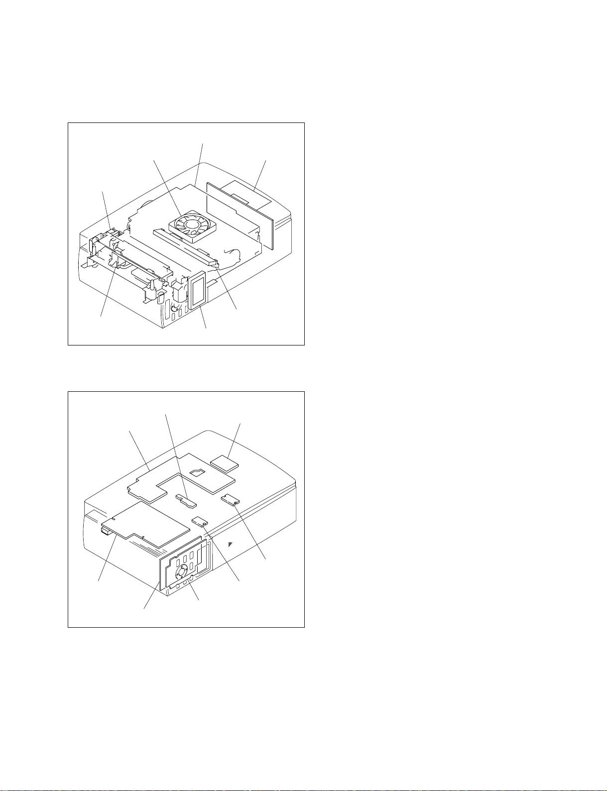
1-1. Main Parts Location
1-1-1. Main Block Location
Section 1
Service Overview
F chassis assembly
DC fan
Paper eject
guide assembly
K frame assembly
1-1-2. Board Location
RM-46 board
MD-46 board
Switching
regulator
Thermal head
LCD
UV-46 board
DK-46 board
DPP-EX50 V1
JD-46 board
PE-46 board
SW-46 board
MC-46 board
1-1
Page 8
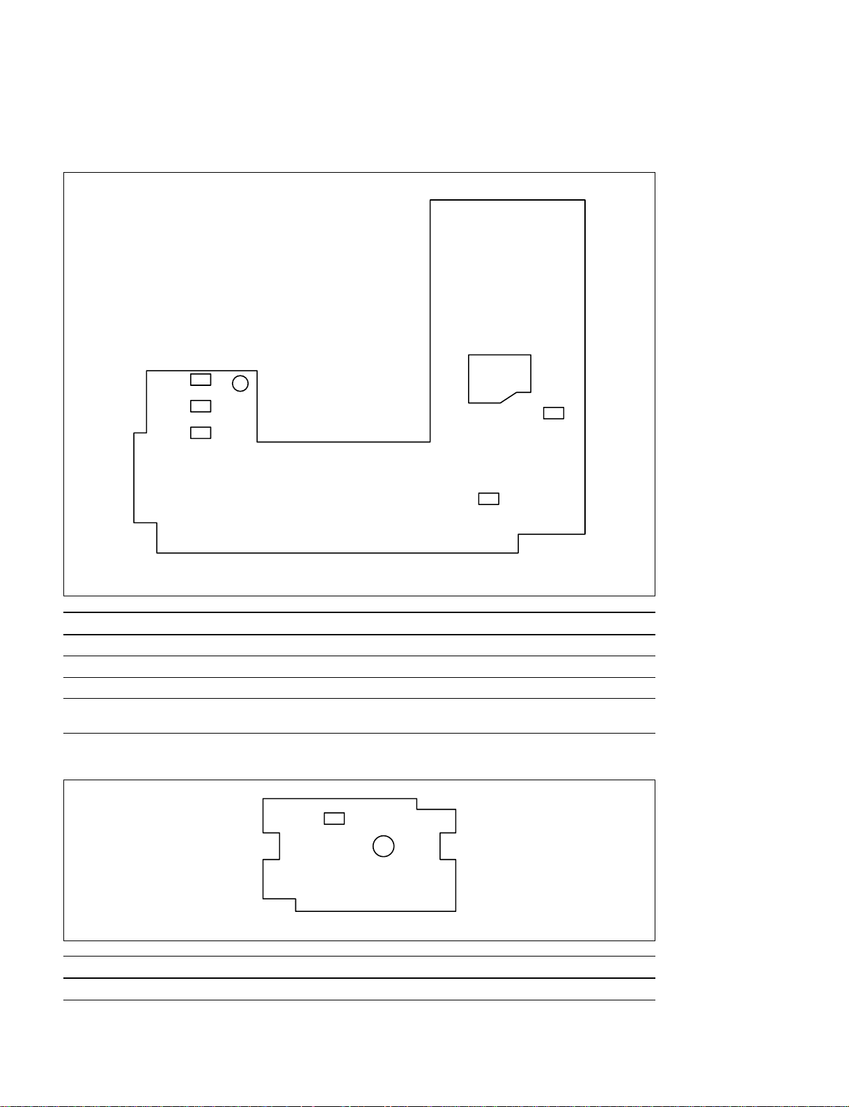
1-1-3. Sensor Location and Function Description
MD-46 board
PH901
PH902
PH905
D901
PH903
PH904
MD-46 board (Side B)
Ref No. Name Type Function
PH903, PH904 Mode position sensor Reflective x 2 Detection of DC motor position
PH901, PH902 Ribbon code sensor Reflective x 2 Detection of ribbon type
D901 Ribbon mark sensor LED Detection of ribbon position
PH905 Ribbon in sensor Reflective x 1 Detection of presence or absence of ribbon
cassette
JD-46 board
PH821
JD-46 board (Side B)
Ref No. Name Type Function
PH821 Jamming dead sensor Reflective x 1 Detection of paper position
1-2
DPP-EX50 V1
Page 9
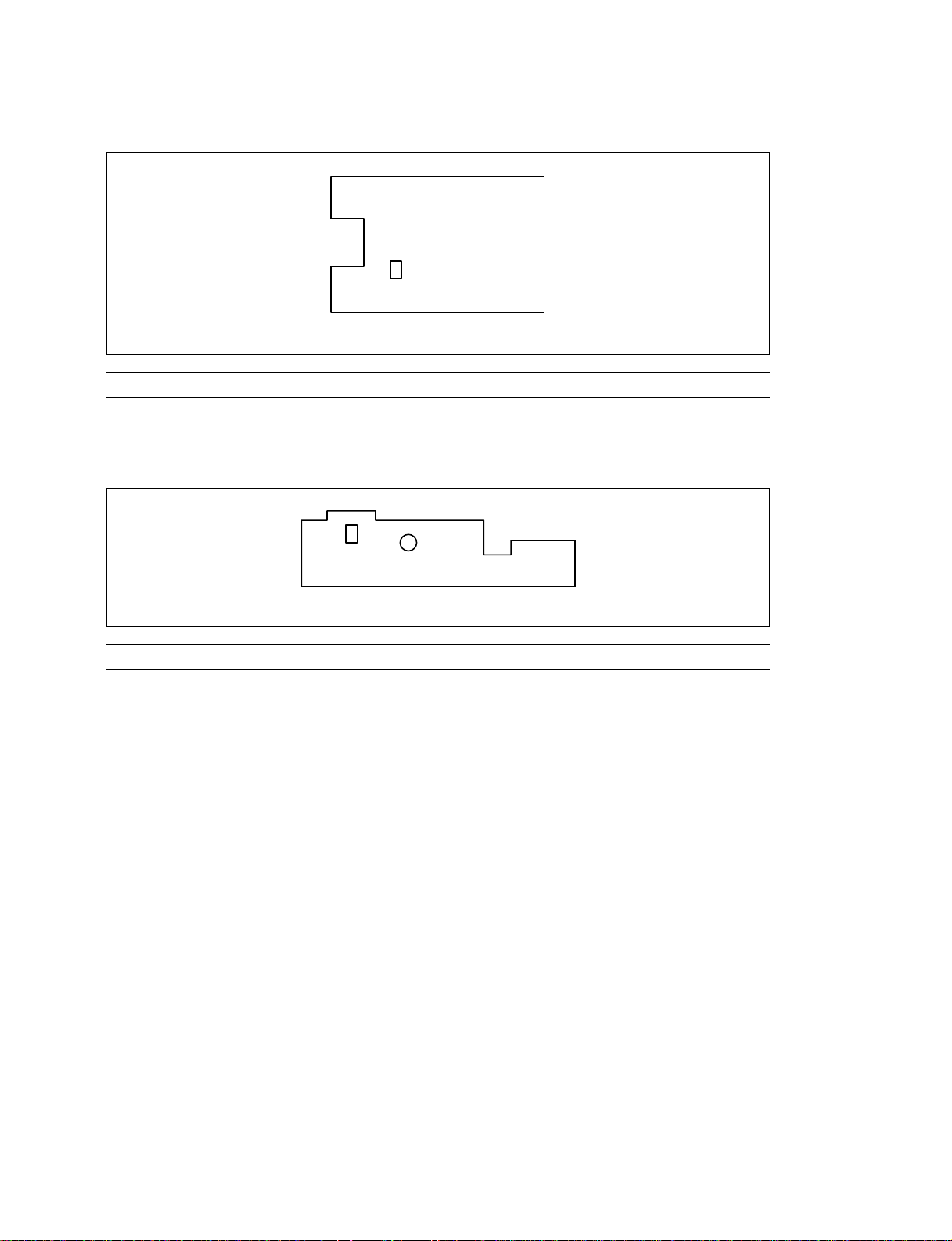
PE-46 board
PH831
PE-46 board (Side B)
Ref No. Name Type Function
PH831 Paper edge sensor Reflective x 1 Detection of paper position
Detection of paper type
RM-46 board
Q841
RM-46 board (Side A)
Ref No. Name Type Function
Q841 Ribbon mark sensor Photo transistor Detection of ribbon position
DPP-EX50 V1
1-3
Page 10
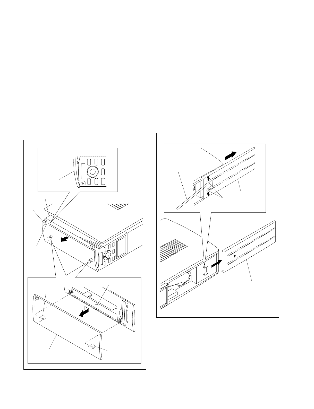
1-2. Removing/Installing the Cabinet
1-2-2. Ribbon Door
n
When replacing the parts, place this unit on the cushion.
1-2-1. Front Door Assembly
1. Open the front door in the direction shown by the
arrow A, then remove the hook [A] from the hole of
the FT panel assembly.
2. Remove the two hooks [B] of the front door from the
cabinet (R) assembly, then remove the front door
assembly in the direction shown by the arrow B.
Hook [A]
Front door
assembly
FT panel assembly
Hook [A]
m
. When removing the two hooks, be careful not to damage
the FT panel assembly.
. When removing the ribbon door, use a stick that is made
of material causing no damage to the FT panel assembly
and is long enough to reach the hooks.
1. Slide the ribbon door in the direction shown by the
arrow A.
2. Remove the two hooks using a stick, then remove the
ribbon door in the direction shown by the arrow A.
A
Stick
Ribbon door
Hooks
A
Hole
Cabinet (R) assembly
Hook [B]
B
Front door assembly
Hook [B]
3. Attach the front door assembly in the reverse order of
steps 1 and 2.
Ribbon door
3. Attach the ribbon door in the reverse order of steps 1
and 2.
1-4
DPP-EX50 V1
Page 11
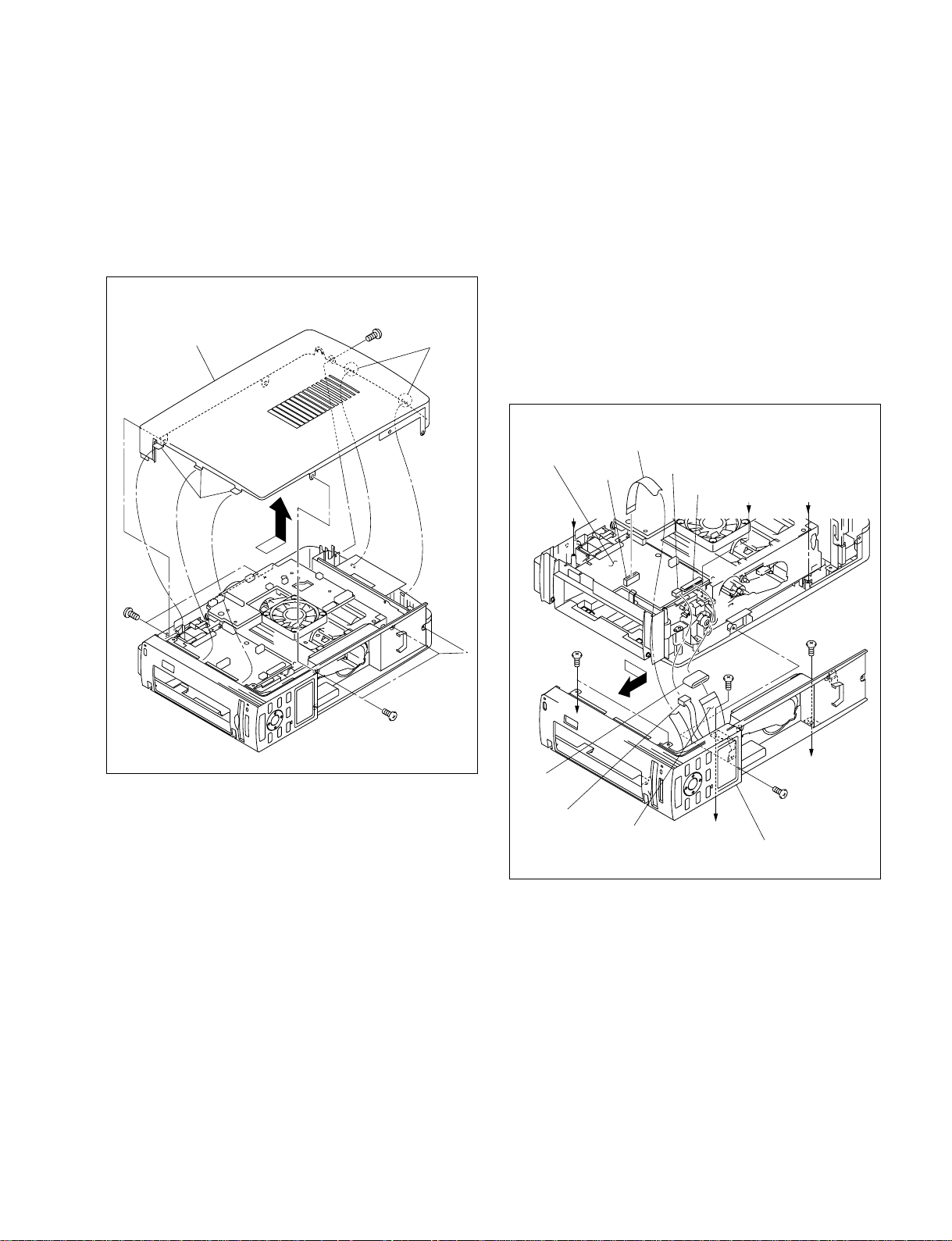
1-2-3. Cabinet (L) Assembly
1-2-4. FT Panel Assembly
1. Remove the front door assembly. (Refer to Section 1-2-1.)
2. Remove the ribbon door. (Refer to Section 1-2-2.)
3. Remove the six screws and five hooks, then remove
the cabinet (L) assembly in the direction shown by the
arrow.
BTP
2.6 x 8
Cabinet (L) assembly
Hooks
BTP
2.6 x 8
Hooks
1. Remove the front door assembly. (Refer to Section 1-2-1.)
2. Remove the ribbon door. (Refer to Section 1-2-2.)
3. Remove the cabinet (L) assembly. (Refer to Section 1-2-3.)
4. Disconnect the harness from the connector (CN302)
on the DK-46 board.
5. Disconnect the two flexible flat cables and the ferrite
core from the connectors (CN203 and CN301) on the
DK-46 board.
6. Remove the four screws (BTP2.6 x 8) and the screw
(BVTT2.6 x 5), then remove the FT panel assembly in
the direction shown by the arrow.
Flexible flat cable
DK-46 board
CN203
A
CN302
CN301
BC
BTP
2.6 x 8
4. Attach the cabinet (L) assembly in the reverse order of
steps 1 to 3.
BTP
BTP
2.6 x 8
Ferrite core
Harness
A
Flexible flat cable
BVTT
2.6 x 5
B
FT panel assembly
2.6 x 8
C
BTP
2.6 x 8
7. Attach the FT panel assembly in the reverse order of
steps 1 to 6.
DPP-EX50 V1
1-5
Page 12
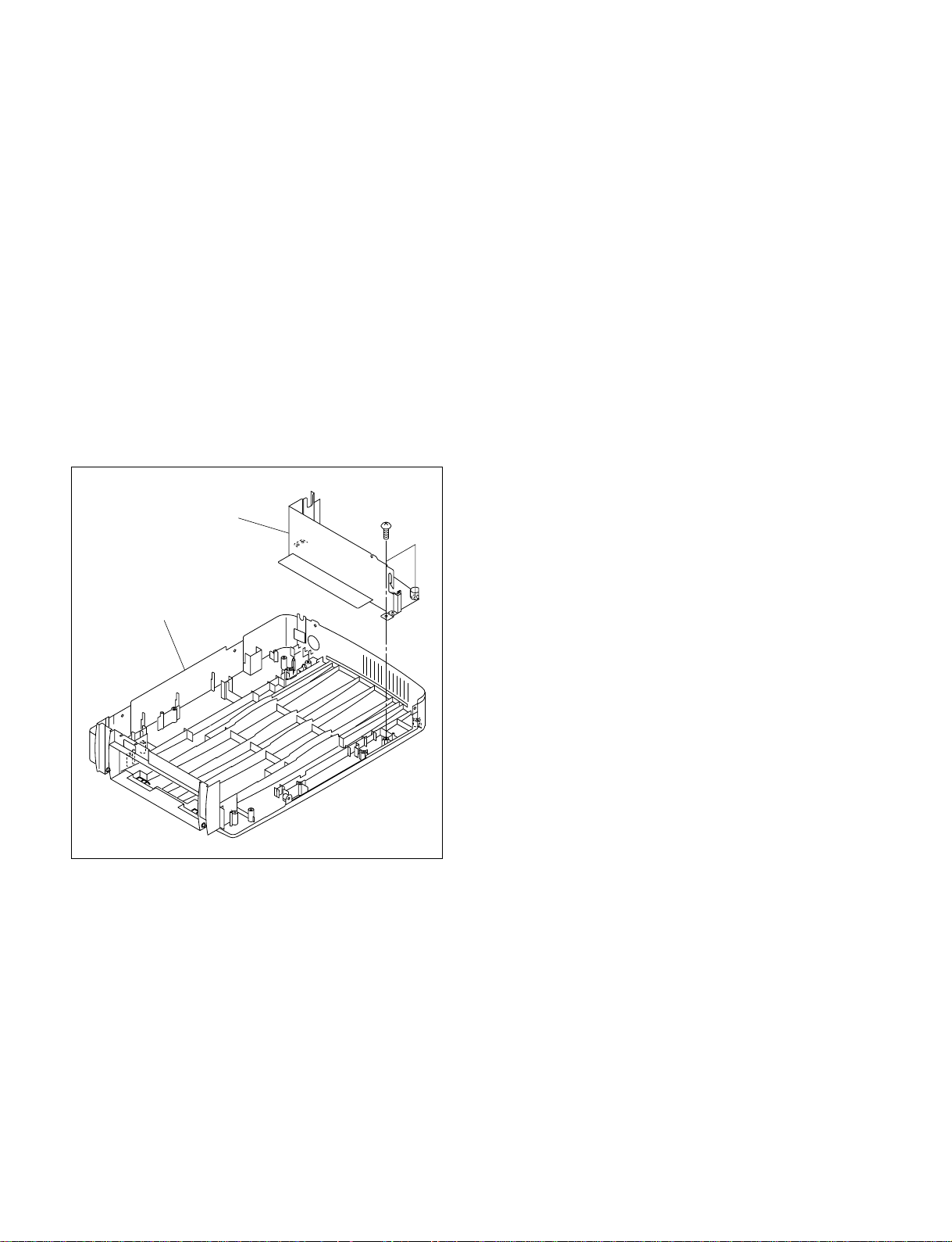
1-2-5. Cabinet (R) Assembly
1. Remove the front door assembly. (Refer to Section 1-2-1.)
2. Remove the ribbon door assembly. (Refer to Section
1-2-2.)
3. Remove the cabinet (L) assembly. (Refer to Section 1-2-3.)
4. Remove the FT panel assembly. (Refer to Section 1-2-4.)
5. Remove the ferrite holder. (Refer to Section 2-8.)
6. Remove the DK-46 board. (Refer to Section 2-1-3.)
7. Remove the paper eject guide assembly. (Refer to
Section 2-3.)
8. Remove the UV-46 board. (Refer to Section 2-1-4.)
9. Remove the F chassis assembly. (Refer to Section 2-4.)
10. Remove the switching regulator. (Refer to Section 2-2.)
11. Remove the two screws, then remove the PS cover
from the cabinet (R) assembly.
PS cover
Cabinet (R) assembly
BTP
2.6 x 8
12. Attach the cabinet (R) assembly in the reverse order of
steps 1 to 11.
1-6
DPP-EX50 V1
Page 13
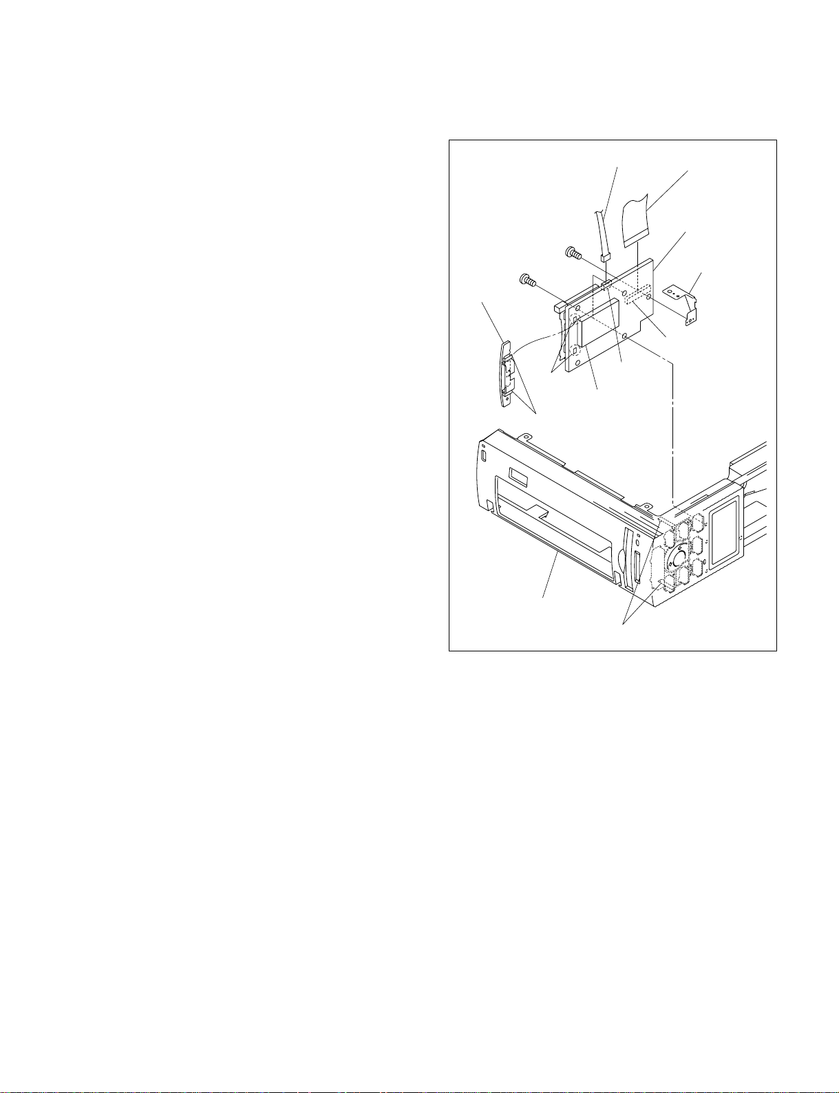
Section 2
Main Parts Replacement
n
When replacing the parts, place this unit on the cushion.
2-1. Replacing the Board
2-1-1. MC-46 Board
1. Remove the front door assembly. (Refer to Section 1-2-1.)
2. Remove the ribbon door. (Refer to Section 1-2-2.)
3. Remove the cabinet (L) assembly. (Refer to Section 1-2-3.)
4. Remove the FT panel assembly. (Refer to Section 1-2-4.)
5. Remove the two screws (PTP2 x 5) and two hooks [A],
then remove the MC-46 board.
6. Disconnect the harness and flexible flat cable from the
connectors (CN453 and CN454) on the MC-46 board.
7. Remove the precision screw (P2 x 3), then remove the
MC earth plate.
8. Remove the two hooks [B] from the holes of the MC46 board, then remove the MS guide.
MS guide
Precision screw
P2 x 3
PTP2 x 5
Holes
Hooks [B]
Harness
CN454
MS
connector
Flexible flat cable
MC-46 board
MC earth plate
CN453
FT panel assembly
Hooks [A]
9. Install the MC-46 board in the reverse order of steps 1
to 8.
DPP-EX50 V1
2-1
Page 14
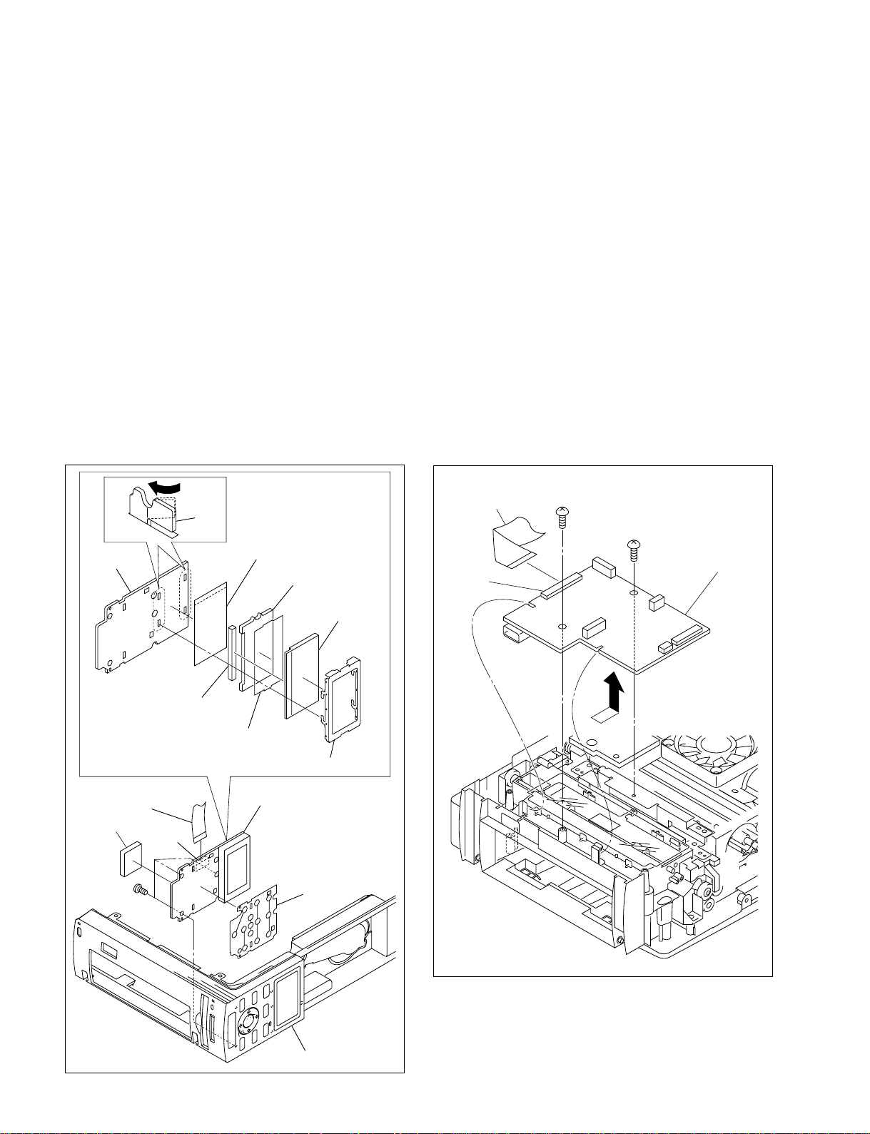
2-1-2. SW-46 Board/LCD
1. Remove the front door assembly. (Refer to Section 1-2-1.)
2. Remove the ribbon door. (Refer to Section 1-2-2.)
3. Remove the cabinet (L) assembly. (Refer to Section 1-2-3.)
4. Remove the FT panel assembly. (Refer to Section 1-2-4.)
5. Remove the MC-46 board. (Refer to Section 2-1-1.)
6. Remove the three screws, then remove the SW-46
board.
7. Disconnect the flexible flat cable from the connector
(CN501) on the SW-46 board.
8. Remove the sheet switch and cushion (MC) from the
SW-46 board.
9. Remove the four hooks from the SW-46 board, then
remove the LCD mounting plate and reflection sheet.
10. Remove the conductive plate for connection, light
conductive plate (LCD), diffusion sheet and LCD from
the LCD mounting plate.
Hook
Hook
Reflection sheet
SW-46 board
SW-46 board
Reflection sheet
Light conductive
Light conductive
plate (LCD)
plate (LCD)
11. Install the SW-46 board and LCD in the reverse order
of steps 1 to 10.
2-1-3. DK-46 Board
n
After replacing the DK-46 board, be sure to upgrade the
firmware (IC102). (Refer to Section 4-3.)
1. Remove the ribbon door. (Refer to Section 1-2-2.)
2. Remove the cabinet (L) assembly. (Refer to Section 1-2-3.)
3. Remove the FT panel assembly. (Refer to Section 1-2-4.)
4. Remove the ferrite holder. (Refer to Section 2-8.)
5. Disconnect the flexible flat cable from the connector
(CN201) on the DK-46 board.
6. Remove the two screws, then remove the DK-46 board
in the direction shown by the arrow.
BTP
Flexible flat cable
CN201
2.6 x 8
BVTT
2.6 x 5
DK-46 board
Flexible flat cable
Flexible flat cable
Cushion (MC)
PTP2 x 5
PTP2 x 5
Conductive plate
Conductive plate
for connection
for connection
CN501
CN501
Diffusion sheet
Diffusion sheet
LCD mounting plate
LCD mounting plate
SW-46 board
SW-46 board
LCD
LCD
Sheet switch
7. Install the DK-46 board in the reverse order of steps 1
to 6.
2-2
FT panel assembly
FT panel assembly
DPP-EX50 V1
Page 15
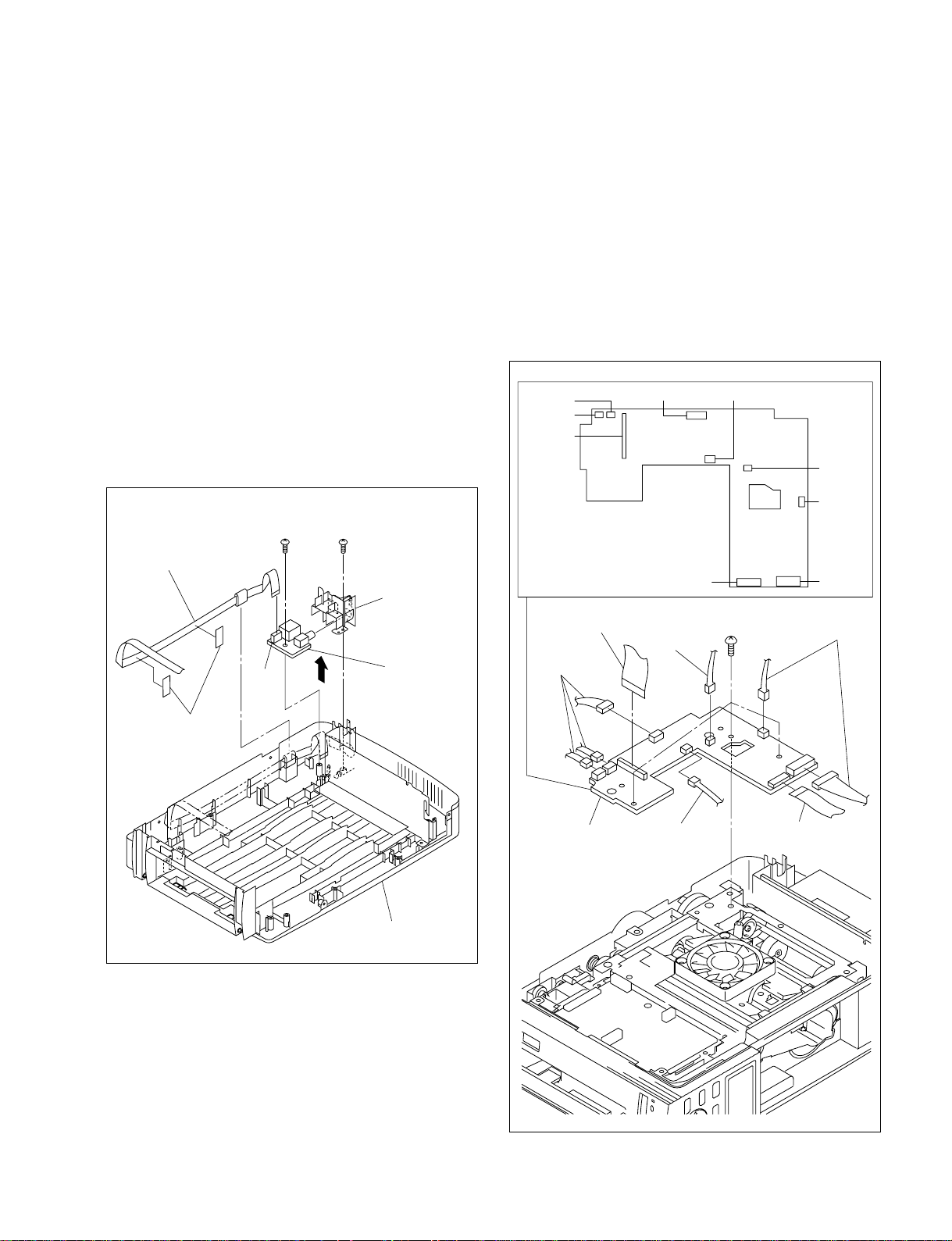
2-1-4. UV-46 Board
BVTT
2.6 x 5
MD-46 board
MD-46 board (Side A)
CN309
CN906
CN910
CN905 CN903
CN904
CN908
CN901CN902
Flexible flat cable
Flexible flat cable
Harnesses
Harnesses
Harness
Harness
2-1-5. MD-46 Board
1. Remove the front door assembly. (Refer to Section 1-2-1.)
2. Remove the ribbon door. (Refer to Section 1-2-2.)
3. Remove the cabinet (L) assembly. (Refer to Section 1-2-3.)
4. Remove the FT panel assembly. (Refer to Section 1-2-4.)
5. Remove the ferrite holder. (Refer to Section 2-8.)
6. Remove the DK-46 board. (Refer to Section 2-1-3.)
7. Remove the paper eject guide assembly. (Refer to
Section 2-3.)
8. Remove the switching regulator. (Refer to Section 2-2.)
9. Remove the F chassis assembly. (Refer to Section 2-4.)
10. Remove the two screws and two filament tapes, then
remove the UV cover and UV-46 board in the
direction shown by the arrow.
11. Disconnect the flexible flat cable from the connector
(CN431) on the UV-46 board.
Flexible flat cable
BTP
2.6 x 8
BTP
2.6 x 8
UV cover
1. Remove the ribbon door. (Refer to Section 1-2-2.)
2. Remove the cabinet (L) assembly. (Refer to Section 1-2-3.)
3. Remove the ferrite holder. (Refer to Section 2-8.)
4. Disconnect the seven harnesses from the connectors
(CN309, CN901, CN903, CN904, CN905, CN906 and
CN908) and two flexible flat cables from the
connectors (CN902 and CN910) on the MD-46 board.
5. Remove the three screws, then remove the MD-46
board.
12. Install the UV-46 board in the reverse order of steps 1
to 11.
Filament
tapes
CN431
UV-46 board
Cabinet (R) assembly
DPP-EX50 V1
6. Install the MD-46 board in the reverse order of steps 1
to 5.
2-3
Page 16

2-1-6. JD-46 Board
2-1-7. PE-46 Board
1. Remove the front door assembly. (Refer to Section 1-2-1.)
2. Remove the ribbon door. (Refer to Section 1-2-2.)
3. Remove the cabinet (L) assembly. (Refer to Section 1-2-3.)
4. Remove the FT panel assembly. (Refer to Section 1-2-4.)
5. Remove the ferrite holder. (Refer to Section 2-8.)
6. Remove the DK-46 board. (Refer to Section 2-1-3.)
7. Remove the paper eject guide assembly. (Refer to
Section 2-3.)
8. Remove the MD-46 board. (Refer to Section 2-1-5.)
9. Remove the F chassis assembly. (Refer to Section 2-4.)
10. Remove the UV-46 board. (Refer to Section 2-1-4.)
11. Remove the screw, then remove the JD-46 board.
12. Disconnect the harness from the connector (CN821)
on the JD-46 board.
F chassis assembly
n
When removing/installing the PE-46 board, be careful not
to break the two hooks.
1. Remove the front door assembly. (Refer to Section 1-2-1.)
2. Remove the ribbon door. (Refer to Section 1-2-2.)
3. Remove the cabinet (L) assembly. (Refer to Section 1-2-3.)
4. Remove the FT panel assembly. (Refer to Section 1-2-4.)
5. Remove the ferrite holder. (Refer to Section 2-8.)
6. Remove the DK-46 board. (Refer to Section 2-1-3.)
7. Remove the paper eject guide assembly. (Refer to
Section 2-3.)
8. Remove the F chassis assembly. (Refer to Section 2-4.)
9. Remove the MD-46 board. (Refer to Section 2-1-5.)
10. Disconnect the harness from the connector (CN831)
on the PE-46 board.
11. Remove the PE-46 board in the direction shown by the
arrow B while pushing the hook of the K frame
assembly in the direction shown by the arrow A.
F chassis assembly
Bottom of
F chassis assembly
PTP2 x 3
CN821
JD-46 board
Harness
13. Install the JD-46 board in the reverse order of steps 1
to 12.
2-4
K frame assembly
K frame assembly
Hook
PE-46 board
A
CN831
Harness
B
Hook
DPP-EX50 V1
Page 17
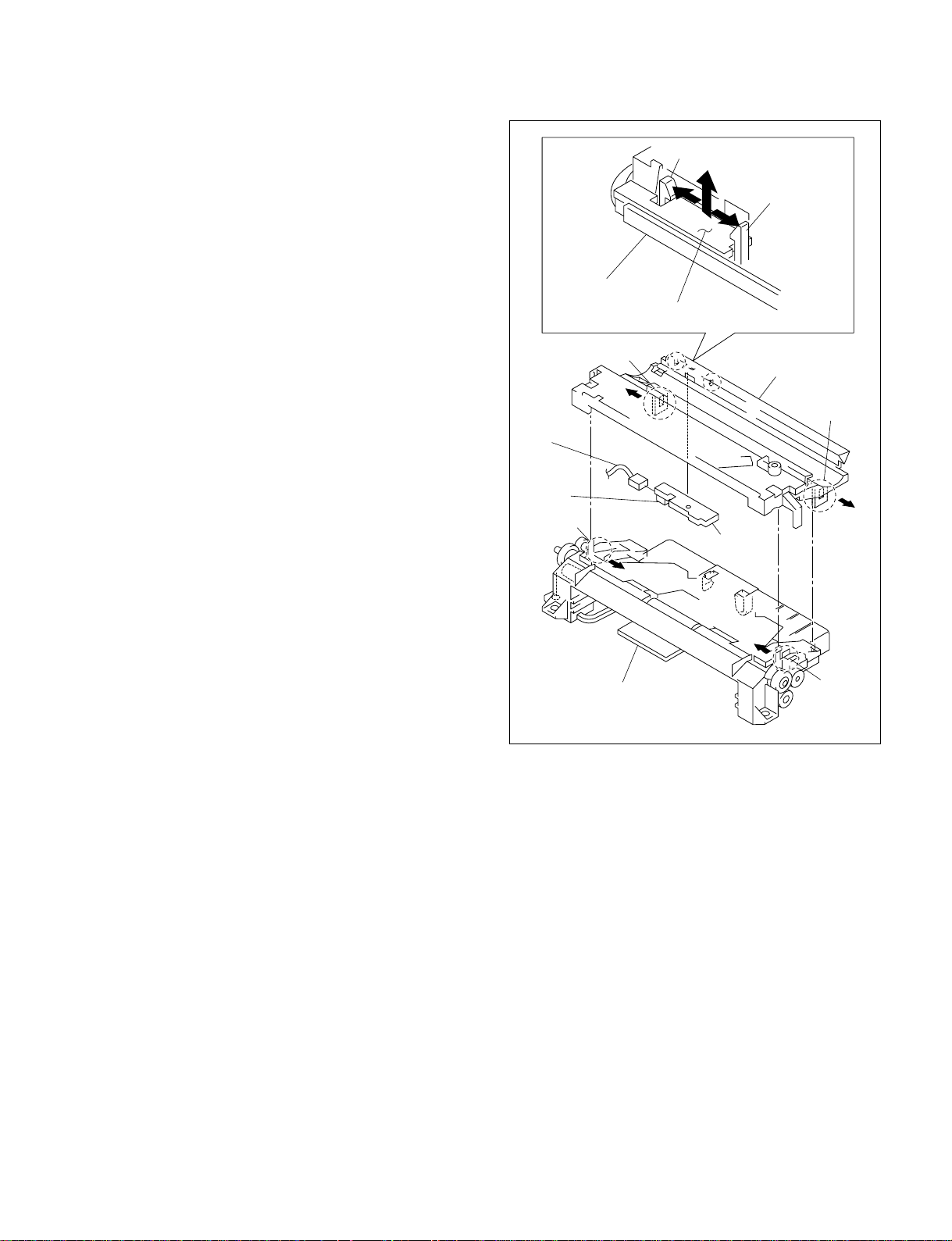
Paper guide assembly
K frame assembly
Hook [A]
Hook [A]
Hook [A]
Hook [A]
A
A
B
RM-46 board
K frame assembly
Hook [B]
Harness
CN841
Hook [B]
RM-46 board
12. Install the PE-46 board in the reverse order of steps 1
to 11.
2-1-8. RM-46 Board
n
When removing/installing the RM-46 board, be careful not
to break the two hooks [B].
1. Remove the front door assembly. (Refer to Section 1-2-1.)
2. Remove the ribbon door. (Refer to Section 1-2-2.)
3. Remove the cabinet (L) assembly. (Refer to Section 1-2-3.)
4. Remove the FT panel assembly. (Refer to Section 1-2-4.)
5. Remove the ferrite holder. (Refer to Section 2-8.)
6. Remove the DK-46 board. (Refer to Section 2-1-3.)
7. Remove the paper eject guide assembly. (Refer to
Section 2-3.)
8. Remove the F chassis assembly. (Refer to Section 2-4.)
9. Remove the MD-46 board. (Refer to Section 2-1-5.)
10. Remove the K frame assembly. (Refer to Section 2-5.)
11. Remove the four hooks [A], then remove the paper
guide assembly from the K frame assembly.
12. Disconnect the harness from the connector (CN841)
on the RM-46 board.
13. Remove the two hooks [B] of the K frame assembly in
the direction shown by the arrow A, then remove the
RM-46 board in the direction shown by the arrow B.
DPP-EX50 V1
14. Install the RM-46 board in the reverse order of steps 1
to 13.
2-5
Page 18

2-2. Switching Regulator
1. Remove the front door assembly. (Refer to Section 1-2-1.)
2. Remove the ribbon door. (Refer to Section 1-2-2.)
3. Remove the cabinet (L) assembly. (Refer to Section 1-2-3.)
4. Remove the FT panel assembly. (Refer to Section 1-2-4.)
5. Remove the screw, then remove the earth lug from the
F chassis assembly.
6. Remove the cord retainer from the cabinet (R) assembly.
7. Remove the switching regulator in the direction shown
by the arrow.
8. Disconnect the two harnesses from the connectors (P1
and P2) on the switching regulator.
9. Attach the switching regulator in the reverse order of
steps 1 to 8.
m
. When attaching the switching regulator, be sure to
securely attach it to the three grooves of the PS
cover.
. When attaching the switching regulator, be sure to
securely hook the harness and earth lug to the
notches of the PS cover.
Switching regulator
Grooves
Harness
Cord retainer
Cabinet (R) assembly
PS cover
PS cover
Groove
BVTT
2.6 x 5
Switching regulator
Harness
P1
P2
Earth lug
2-6
F chassis assembly
Notches of
PS cover
Earth lug
Harness
DPP-EX50 V1
Page 19

2-3. Paper Eject Guide Assembly
2-4. F Chassis Assembly
1. Remove the front door assembly. (Refer to Section 1-2-1.)
2. Remove the ribbon door. (Refer to Section 1-2-2.)
3. Remove the cabinet (L) assembly. (Refer to Section 1-2-3.)
4. Remove the FT panel assembly. (Refer to Section 1-2-4.)
5. Remove the ferrite holder. (Refer to Section 2-8.)
6. Remove the DK-46 board. (Refer to Section 2-1-3.)
7. Disconnect the two harnesses from the connectors
(CN309 and CN906) on the MD-46 board, then
remove the two harnesses from the notch of the paper
eject guide assembly.
8. Remove the two screws (BVTP2.6 x 8) and the screw
(BVTT2.6 x 5), then remove the paper eject guide
assembly.
BVTT
2.6 x 5
Notch
BVTP
2.6 x 8
Paper eject guide
assembly
1. Remove the front door assembly. (Refer to Section 1-2-1.)
2. Remove the ribbon door. (Refer to Section 1-2-2.)
3. Remove the cabinet (L) assembly. (Refer to Section 1-2-3.)
4. Remove the FT panel assembly. (Refer to Section 1-2-4.)
5. Remove the ferrite holder. (Refer to Section 2-8.)
6. Remove the DK-46 board. (Refer to Section 2-1-3.)
7. Remove the switching regulator. (Refer to Section 2-2.)
8. Remove the paper eject guide assembly. (Refer to
Section 2-3.)
9. Remove the three screws, then remove the F chassis
assembly.
BVTP
2.6 x 8
BVTP
2.6 x 8
F chassis assembly
Harnesses
CN906
CN309
MD-46 board
9. Attach the paper eject guide assembly in the reverse
order of steps 1 to 8.
10. Attach the F chassis assembly in the reverse order of
steps 1 to 9.
DPP-EX50 V1
2-7
Page 20

2-5. K Frame Assembly
1. Remove the front door assembly. (Refer to Section 1-2-1.)
2. Remove the ribbon door. (Refer to Section 1-2-2.)
3. Remove the cabinet (L) assembly. (Refer to Section 1-2-3.)
4. Remove the FT panel assembly. (Refer to Section 1-2-4.)
5. Remove the ferrite holder. (Refer to Section 2-8.)
6. Remove the DK-46 board. (Refer to Section2-1-3.)
7. Remove the paper eject guide assembly. (Refer to
Section 2-3.)
8. Remove the F chassis assembly. (Refer to Section 2-4.)
9. Remove the two screws (BVTT2.6 x 5), then remove
the K frame holder.
10. Remove the screw (BVTP2.6 x 8), then remove the K
frame assembly in the direction shown by the arrow.
Holes
Hooks
11. Attach the K frame assembly in the reverse order of
steps 1 to 10.
m
. When attaching the K frame assembly, attach it
while pushing the pendulum gear in the direction
shown by the arrow.
. When attaching the K frame assembly, be sure to
securely insert the four hooks of the F chassis
assembly into the four holes of the K frame
assembly.
2-6. DC Fan
1. Remove the front door assembly. (Refer to Section 1-2-1.)
2. Remove the ribbon door. (Refer to Section 1-2-2.)
3. Remove the cabinet (L) assembly. (Refer to Section 1-2-3.)
4. Remove the two screws and disconnect the harness
from the connector (CN903) on the MD-46 board, then
remove the DC fan.
K frame assembly
BVTP
x
8
2.6
K frame assembly
Pendulum gear
F chassis assembly
BVTT
2.6
x
5
K frame holder
Holes
F chassis assembly
F chassis assembly
Hooks
K frame assembly
Harness
CN903
MD-46 board
PS3 x 10
DC fan
5. Attach the DC fan in the reverse order of steps 1 to 4.
2-8
DPP-EX50 V1
Page 21

2-7. Thermal Head
2-8. Ferrite Holder
m
. When replacing the thermal head, be sure to remove the
center shim from the thermal head and attach it to the
new one.
. After replacing the thermal head, be sure to adjust the
density. (Refer to Section 3-3.)
Before replacing the thermal head, be sure to print the
test pattern (gray pattern) as the reference of density.
1. Remove the front door assembly. (Refer to Section 1-2-1.)
2. Remove the ribbon door. (Refer to Section 1-2-2.)
3. Remove the cabinet (L) assembly. (Refer to Section 1-2-3.)
4. Remove the FT panel assembly. (Refer to Section 1-2-4.)
5. Remove the ferrite holder. (Refer to Section 2-8.)
6. Remove the DK-46 board. (Refer to Section 2-1-3.)
7. Remove the paper eject guide assembly. (Refer to
Section 2-3.)
8. Remove the MD-46 board. (Refer to Section 2-1-5.)
9. Remove the F chassis assembly. (Refer to Section 2-4.)
10. Remove the DC fan. (Refer to Section 2-6.)
11. Pull out the portion A of connectors on the thermal
head in the direction shown by the arrow, then remove
the two flexible flat cables.
12. Remove the two screws, then remove the thermal head.
13. Remove the center shim from the thermal head.
1. Remove the front door assembly. (Refer to Section 1-2-1.)
2. Remove the ribbon door. (Refer to Section 1-2-2.)
3. Remove the cabinet (L) assembly. (Refer to Section 1-2-3.)
4. Disconnect the two flexible flat cables from the
connectors (CN104 and CN202) on the DK-46 board.
5. Remove the two ferrite beads and two flexible flat
cables from the ferrite holder.
Ferrite holder
Ferrite bead (Large)
Ferrite bead
(Small)
Flexible
flat cables
PSW
2.6 x 7
F chassis assembly
Flexible flat cables
Thermal head
Center shim
A
Connector
A
14. Attach the thermal head in the reverse order of steps 1
to 13.
DK-46 boardCN104CN202
6. Attach the ferrite holder in the reverse order of steps 1
to 5.
DPP-EX50 V1
2-9
Page 22

2-9. Stepping Motor
2-10. E Capstan Roller
1. Remove the front door assembly. (Refer to Section 1-2-1.)
2. Remove the ribbon door. (Refer to Section 1-2-2.)
3. Remove the cabinet (L) assembly. (Refer to Section 1-2-3.)
4. Remove the FT panel assembly. (Refer to Section 1-2-4.)
5. Remove the ferrite holder. (Refer to Section 2-8.)
6. Remove the DK-46 board. (Refer to Section 2-1-3.)
7. Remove the paper eject guide assembly. (Refer to
Section 2-3.)
8. Remove the switching regulator. (Refer to Section 2-2.)
9. Remove the F chassis assembly. (Refer to Section 2-4.)
10. Remove the two screws and disconnect the harness
from the connector (CN905) on the MD-46 board, then
remove the stepping motor.
BVTT
2.6 x 5
Harness
Stepping motor
CN905
n
When replacing the E capstan roller, platen roller or pinch
roller, be careful not to touch the roller with bare hands or
dirty gloves. In case that the roller is contaminated, wipe it
with ethyl alcohol.
1. Remove the front door assembly. (Refer to Section 1-2-1.)
2. Remove the ribbon door. (Refer to Section 1-2-2.)
3. Remove the cabinet (L) assembly. (Refer to Section 1-2-3.)
4. Remove the FT panel assembly. (Refer to Section 1-2-4.)
5. Remove the ferrite holder. (Refer to Section 2-8.)
6. Remove the DK-46 board. (Refer to Section 2-1-3.)
7. Remove the paper eject guide assembly. (Refer to
Section 2-3.)
8. Remove the switching regulator. (Refer to Section 2-2.)
9. Remove the F chassis assembly. (Refer to Section 2-4.)
10. Remove the K frame assembly. (Refer to Section 2-5.)
11. Remove the stepping motor. (Refer to Section 2-9.)
12. Remove the two screws, then remove the reinforcing
plate (L).
13. Remove the four screws, then remove the E transmission
gear assembly.
MD-46 board
11. Attach the stepping motor in the reverse order of step 1
to 10.
BVTT
2.6 x 5
Reinforcing plate (L)
E transmission
gear assembly F chassis assembly
BVTT
2.6 x 5
2-10
DPP-EX50 V1
Page 23

14. Remove the R pendulum lever assembly.
15. Remove the screw, then remove the CP shaft earth.
16. Rotate the two roller bearings in the direction shown
by the arrow A, then remove them.
17. Move the platen roller in the direction shown by the
arrow B, then remove it in the direction shown by the
arrow C.
18. Rotate the two roller bearings in the direction shown
by the arrow A, then remove them.
19. Remove the poly washer from the hole for the roller
bearing.
20. Move the E capstan roller in the direction shown by
the arrow B, then remove it in the direction shown by
the arrow C.
BVTT
2.6 x 5
CP shaft earth
A
R pendulum
lever assembly
Platen roller
Roller bearing
B
Hole for the roller bearing
Poly washer
E capstan roller
Roller
bearing
Roller bearing
A
A
Pinch roller
C
DPP-EX50 V1
B
A
Poly washer
Roller
bearing
C
E capstan roller
21. Attach the E capstan roller in the reverse order of steps
1 to 20.
2-11
Page 24

Page 25

Section 3
Service Mode
n
The selected item on the screen displayed in the service mode is framed by “yellow frame”. In this
manual, the yellow frame is referred to as “frame”.
3-1. Operation panel
Monitor out key
Monitor out LED
Power key
Input select key
Menu key
Picture key
Cancel key
Print key
Auto print key
Enter key
Arrow key
DPP-EX50 V1
3-1
Page 26

3-2. Activation
m
When executing the service mode, be sure to follow the precautions below.
. Do not use the mode that is not described in this manual.
. Operate each mode according to the operation procedure in this manual.
Connection
1. Insert the power cord of this unit (DPP-EX50) into the receptacle.
2. Connect the color monitor to the VIDEO OUT connector of this unit using the video cable.
Procedure
1. Press the Power key while pressing the Menu and Enter keys simultaneously.
2. Release all keys when the initial screen (screen 3-1) in the service mode is displayed on the color
monitor.
(Screen 3-1)
n
Select each mode using the Arrow key (framed item) and press the Enter key.
3-2
DPP-EX50 V1
Page 27

3-3. Density Adjustment during Thermal Head Replacement
Preparation
Before replacing the thermal head, print a test pattern (gray pattern) as the reference of density using an
old thermal head (before replacement) or normal unit (DPP-EX50).
n
For the test pattern of an old thermal head, use the one that is not damaged as a whole by black and white
stripes due to the defective thermal head. In case that the test pattern of an old thermal head is in the state
that cannot be used as the reference, use the test pattern printed by the normal unit (DPP-EX50).
Procedure
1. Set the ribbon and paper to this unit.
n
Use the set paper below.
Small-size photo paper SVM-30SS
2. Start the service mode (refer to Section 3-2), shift the frame to “Mechanic Test” using the Arrow key,
and press the Enter key.
(Screen 3-2)
3. Press the Print key when the screen (screen 3-3) is displayed on the color monitor. This unit initiates
the printing of a density confirmation pattern (gray).
(Screen 3-3)
DPP-EX50 V1
3-3
Page 28
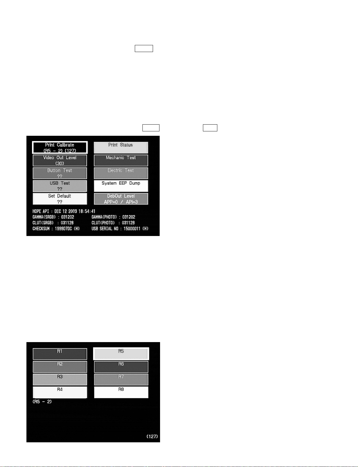
4. When the printing is completed, press the Cancel key
5. When the screen 3-2 (screen in step 2) is displayed on the color monitor, turn off the power and
disconnect the power cord from the receptacle.
6. Replace the thermal head. (Refer to Section 2-7.)
m
. When replacing the thermal head, confirm the resistance value of old and new thermal heads, and
find the difference in the resistance value.
. The resistance value of thermal head is described beside the thermal head.
7. After replacing the thermal head, insert the power cord into the receptacle and turn on the power.
8. Start the service mode. (Refer to Section 3-2.)
9. Shift the frame to “Print Calibrate” using the Arrow key, and press the Enter key. (Screen 3-4)
(Screen 3-4)
10. When the screen (screen 3-5) is displayed on the color monitor, confirm the display in parenthesis in
the lower-left position. (In the screen example, “R5-2” is displayed.)
The print voltage after replacement is determined by the difference between the display in parenthesis
and the thermal head resistance value in step 6.
n
The voltage applied to the thermal head is changed by the thermal head resistance value. The change
in a voltage is adjusted in two levels.
For eight steps (R1 to R8) (Screen 3-5)
In this case, “R1” has the lowest resistance value of a thermal head. The difference in resistance value is
approximately 300 Z for each step.
3-4
(Screen 3-5)
DPP-EX50 V1
Page 29

For seven steps (R1 to R7) (Screen 3-6)
In this case, “1” has the lowest resistance value of a thermal head. The difference in resistance value is
approximately 70 Z for each step.
(Example)
(Screen 3-6)
Screens 3-5 and 3-6 show the procedure to be taken for the change in thermal head resistance value.
(R5-2) is displayed in the screen example.
(1) Make the first level adjustment.
In the case that the resistance after replacement of thermal head is between
++
ZZ
+300
Z
++
ZZ
__
_70 and
__
The state of screen 3-5 is acceptable.
In the case that the resistance after replacement of thermal head is less than 70
(decrease by one step)
Shift the frame to (R4) using the Arrow key.
In the case that the resistance after replacement of thermal head is 300
ZZ
Z or more
ZZ
(increase by one step)
Shift the frame to (R6) using the Arrow key.
(2) Press the Print key.
Printing is initiated and the screen (screen 3-6) is displayed on the color monitor.
(3) Make the second level adjustment
Shift the frame by the difference in thermal head resistance value using the Arrow key. Then,
press the Enter key.
ZZ
Z
ZZ
DPP-EX50 V1
In the case that the difference in resistance value after replacement of thermal
head is within ±35
ZZ
Z
ZZ
The state of screen 3-6 is acceptable.
In the case that the difference in resistance value after replacement of thermal
++
head is
ZZ
+120
Z (increase by two steps)
++
ZZ
Shift the frame to (4) using the Arrow key.
(In this case, shift the frame by two steps because the difference of each step is approximately 70 Z.)
3-5
Page 30

In the case that the difference in resistance value after replacement of thermal
++
head is
ZZ
+360
Z (increase by one steps)
++
ZZ
Shift the frame to (3) using the Arrow key.
The print is made after the frame is shifted from (R5) to (R6) in the first level adjustment.
Therefore approximately 300 Z is already shifted by the shift of R. Shift the frame by one step to
a larger number for the remaining 60 Z.
(4) Press the Enter key.
The screen (screen 3-7) is displayed. When the step is changed by the resistance value, the
numeric character in parenthesis displayed under “Print Calibrate” changes.
(Screen 3-7)
11. Print a density confirmation pattern (gray) according to the method in steps 2 to 4.
12. Confirm that the print result is equal to the density of a test pattern as reference.
If fine adjustment is required, perform steps 7 and later again.
n
Use the test pattern as reference printed in “Preparation” in this Section.
13. Press the Cancel key to return the display to the initial screen of the service mode.
14. Turn off the power and disconnect the power cord from the receptacle.
3-6
DPP-EX50 V1
Page 31

3-4. Confirmation and Adjustment of Video Output Level
n
Connect the equipment below when confirming and adjusting the level of a video output signal.
Required equipment
. Color monitor (with VIDEO IN connector)
. Oscilloscope (with a band of more than 30 MHz)
. 75 Z terminator
Connection diagram
DPP-EX50
VIDEO
OUT
DPP-EX50
VIDEO
OUT
Video cable
Connection diagram 1
75 Z
terminator
Connection diagram 2
Color monitor
VIDEO IN
GND
Oscilloscope
GND
DPP-EX50 V1
3-7
Page 32
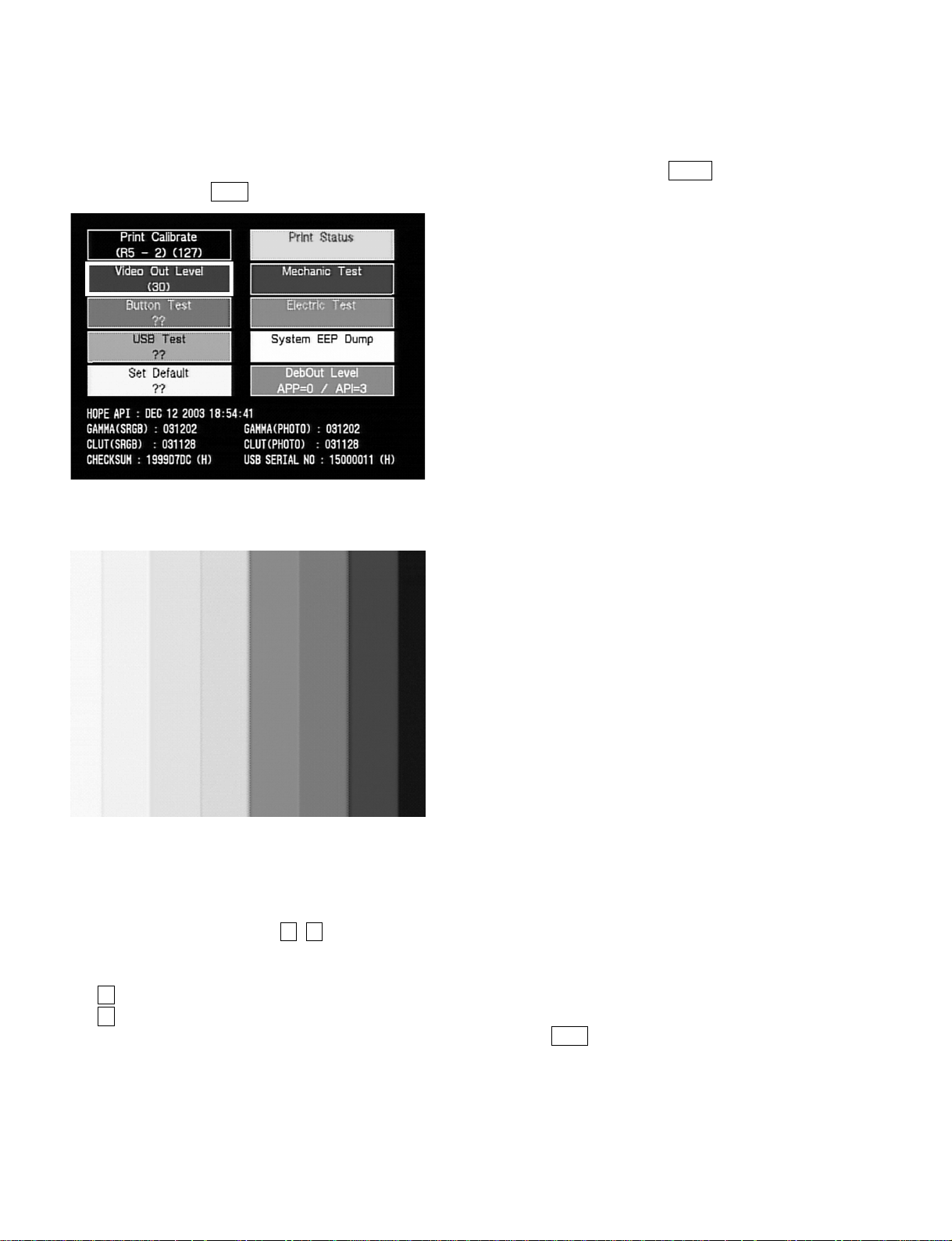
Procedure
1. Connect the color monitor to the VIDEO OUT connector of this unit. (Connection diagram 1)
2. Start the service mode (refer to Section 3-2), shift the frame to “Video Out level” using the Arrow
key, and press the Enter key.
(Screen 3-8)
The screen below is displayed on the color monitor.
(Screen 3-9)
3. Remove the color monitor from this unit.
4. Attach the 75 Z terminator to the VIDEO OUT connector of this unit and connect the oscilloscope to
the 75 Z terminator at both ends. (Connection diagram 2)
5. Adjust using the Arrow key ( ↑ ,
) so that the video output level (SYNC to 100% white) meets the
↓
specification.
Specification: 1.00 ±0.05 V p-p
key: Increases the video output level
↑
key: Decreases the video output level
↓
6. Confirm that the video output level meets the specification and press the Enter key.
7. Remove the oscilloscope.
8. Remove the 75 Z terminator from this unit.
9. Connect the color monitor to the VIDEO OUT connector of this unit. (Connection diagram 1)
10. When the color monitor screen returns to the screen in step 2, turn off the power and disconnect the
power cord from the receptacle.
3-8
DPP-EX50 V1
Page 33

3-5. Operation Check of Key, Fan, LED, LCD and Buzzer
The operation check of “key”, “fan”, “LED”, “LCD” and “buzzer” can be performed in the service mode.
Procedure
1. Start the service mode (refer to Section 3-2), shift the frame to “Button Test” using the Arrow key,
and press the Enter key.
(Screen 3-10)
The screen below is displayed on the color monitor.
(Screen 3-11)
DPP-EX50 V1
3-9
Page 34
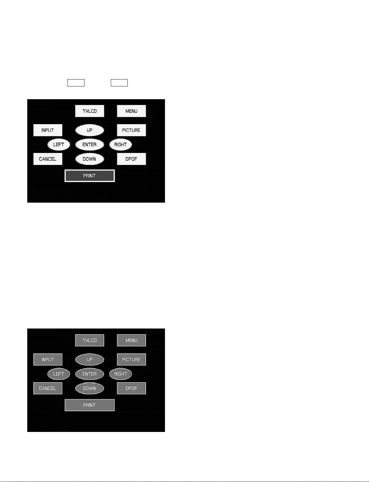
Key operation check
Press the key on the operation panel of this unit. The pressed key is displayed in yellow on the color
monitor.
n
Do not press the Power key. If the Power key is pressed, the power is turned off and the unit enters
standby state.
(Screen 3-12)
LED operation check
“Access LED” and “TV output LED” are lit during “Button Test”. When all keys are pressed, “Access
LED” and “TV output LED” start blinking.
LCD operation check
All segment become ON during “Button Test”. When all 12 keys are pressed, all segment start blinking.
Fan operation check
The fan rotates by force during “Button Test”.
Buzzer check
When all 12 keys are pressed, the buzzer makes a “beep sound” and the all keys on the color monitor are
displayed in red.
3-10
(Screen 3-13)
DPP-EX50 V1
Page 35

When all “key” checks are completed without problem, the display returns to the initial screen of the
service mode. Then, “OK” is displayed under “Button Test”.
(Screen 3-14)
DPP-EX50 V1
3-11
Page 36
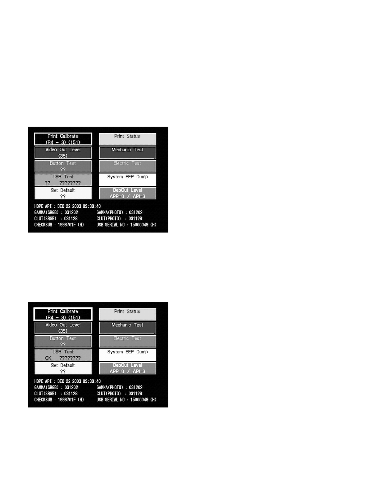
3-6. USB Host and Device Communication Check
The communication check of USB output connector (USB device, rear portion) and PictBridge connector
(USB host, front portion) of this unit can be performed in the service mode.
Procedure
1. Start the service mode. (Refer to Section 3-2.)
n
In this check, it is not required to shift the frame.
(Screen 3-15)
2. Connect the PictBridge connector with the USB output connector using the USB cable.
Specification: The first two “??” displays of “USB Test” should be changed to “OK”.
n
If “NG” or “??” is displayed, there is a problem in the PictBridge connector or in the USB output
connector.
(Screen 3-16)
3-12
DPP-EX50 V1
Page 37

3-7. Mechanical Operation Check
The mechanical operation check can be performed in the service mode.
Procedure
1. Start the service mode (refer to Section 3-2), shift the frame to “Mechanic Test” using the Arrow key,
and press the Enter key.
(Screen 3-17)
The screen below is displayed on the color monitor.
(Screen 3-18)
DPP-EX50 V1
3-13
Page 38

Operation Description
The operations of this unit can be performed by pressing the keys on the operation panel.
n
Do not press the keys other than those described below.
. “INPUT SELECT”: When the Input select key is pressed, the head position returns to M0.
. “UP”: When the Arrow key ( ↑ ) is pressed, the head position comes down.
. “DOWN”: When the Arrow (
) is pressed, the head position comes up.
↓
. “MENU”: When the Menu key is pressed, an aging of head motor is performed.
Repeats back and forth 10 times between the positions M0 and M5.
When the Menu key is pressed during operation, the operation stops.
. “ENTER”: When the Enter key is pressed, the thermal head position moves according to the
printing sequence.
The thermal head position moves in the following order every time the Enter key
is pressed.
Y detection: M0 → M03 → M0 → M1 → M32 → M4
Y print: M3 → M4 → M5 → M4 → M31 → M4
M print: M3 → M4 → M5 → M4 → M31 → M4
C print: M3 → M4 → M5 → M4 → M31 → M4
L print: M3 → M4 → M5 → M31 → M4 → M4
When the Cancel key and then Enter key are pressed during operation, the
operation stops.
. “RIGHT”: When the Arrow (→) key is pressed, the stepping motor moves in the paper
feed direction.
Every time the Arrow (→) key is pressed, the speed changes.
(2400 pps → 8000 pps → stop)
. “LEFT”: When the Arrow (→) key is pressed, the stepping motor moves in the paper eject
direction.
Every time the Arrow (→) key is pressed, the speed changes.
(2400 pps → 8000 pps → stop)
. “TV/LCD”: When the Monitor out key is pressed, an aging of stepping motor is performed.
The following is repeated 100 times.
2400 pps CW current H → 2400 pps CW current M → 2400 pps CCW current H →
2400 pps CCW current M
When the Monitor out key is pressed during operation, the operation stops.
. “PICTURE”: When the Arrow key (← or →) is pressed and the Picture key is pressed during
stepping motor operation, the current is switched.
Every time the Picture key is pressed, the current is switched and repeated as follows.
Current H → Current M → Current L
. “PRINT”: When the Print key is pressed, the test printing (gray) is initiated.
2. Press the Cancel key to return the display to the initial screen in the service mode. (Exit the
mechanical operation mode.)
3. Turn off the power and disconnect the power cord from the receptacle.
3-14
DPP-EX50 V1
Page 39

Section 4
Troubleshooting
4-1. Electrical Troubleshooting
n
For the location of each key, refer to Section 3-1.
Trouble: No video signal is output. (No screen is displayed on the monitor.)
Remedy: . Confirm the flexible flat cable (DK-UV) and connector.
. Confirm IC101 and IC114 on the DK-46 board, and peripheral circuit.
. Confirm J431 on the UV-46 board and peripheral circuit.
Trouble: No Memory Stick image can be read.
Remedy: . Confirm that the Input select key on the operation panel of this unit is set to Memory Stick.
. Confirm the flexible flat cable (DK-MC) and connector.
. Confirm the harness (MC-46) and connector.
. Confirm CN502 on the MC-46 board and peripheral circuit.
. Confirm IC101 on the DK-46 board and peripheral circuit.
. Confirm that the image in the Memory Stick is based on the compatible file format.
. Confirm that the Memory Stick operates correctly.
Trouble: No Compact Flash image can be read.
Remedy: . Confirm that the Input select key on the operation panel of this unit is set to Compact Flash.
. Confirm the flexible flat cable (DK-MC) and connector.
. Confirm the harness (MC-46) and connector.
. Confirm CN451 on the MC-46 board and peripheral circuit.
. Confirm IC101 and IC301 to IC308 on the DK-46 board, and peripheral circuit.
. Confirm that the image in the Compact Flash is based on the compatible file format.
. Confirm that the Compact Flash operates correctly.
Trouble: This unit is not recognized by the personal computer
Remedy: . Confirm the flexible flat cable (DK-UV) and connector.
. Confirm IC101 on the DK-46 board and peripheral circuit.
. Confirm CN432 on the UV-46 board and peripheral circuit.
. Confirm the communication by “USB Test” in the service mode. (Refer to Section 3-6.)
Trouble: This unit is not recognized by the camera compatible with PictBridge.
. Confirm IC101, IC112 and CN402 on the DK-46 board, and peripheral circuit.
. Confirm that the camera is compatible with PictBridge.
. Confirm the communication by “USB Test” in the service mode. (Refer to Section 3-6.)
Trouble: Keys on the operation panel cannot be operated.
Remedy: . Confirm the flexible flat cable (DK-SW) and connector.
. Confirm IC201 on the DK-46 board and peripheral circuit.
. Confirm the key operation by “Button Test” in the service mode. (Refer to Section 3-5.)
Trouble: LCD (Liquid Crystal Display) displays nothing.
Remedy: . Confirm the flexible flat cable (DK-SW) and connector.
. Confirm IC101 on the DK-46 board and peripheral circuit.
. Confirm the LCD operation by “Button Test” in the service mode. (Refer to Section 3-5.)
DPP-EX50 V1
4-1
Page 40
Trouble: Color and image of print result is not normal.
Remedy: . Print the density confirmation pattern (gray) by “Mechanic Test” in the service mode and
confirm the image. (Refer to Section 3-1.)
. Confirm the flexible flat cable (DK-HE) and connector.
. Confirm the flexible flat cable (MD-HE) and connector.
. Confirm IC201, IC204 and IC231 on the DK-46 board, and peripheral circuit.
4-2. Error Display
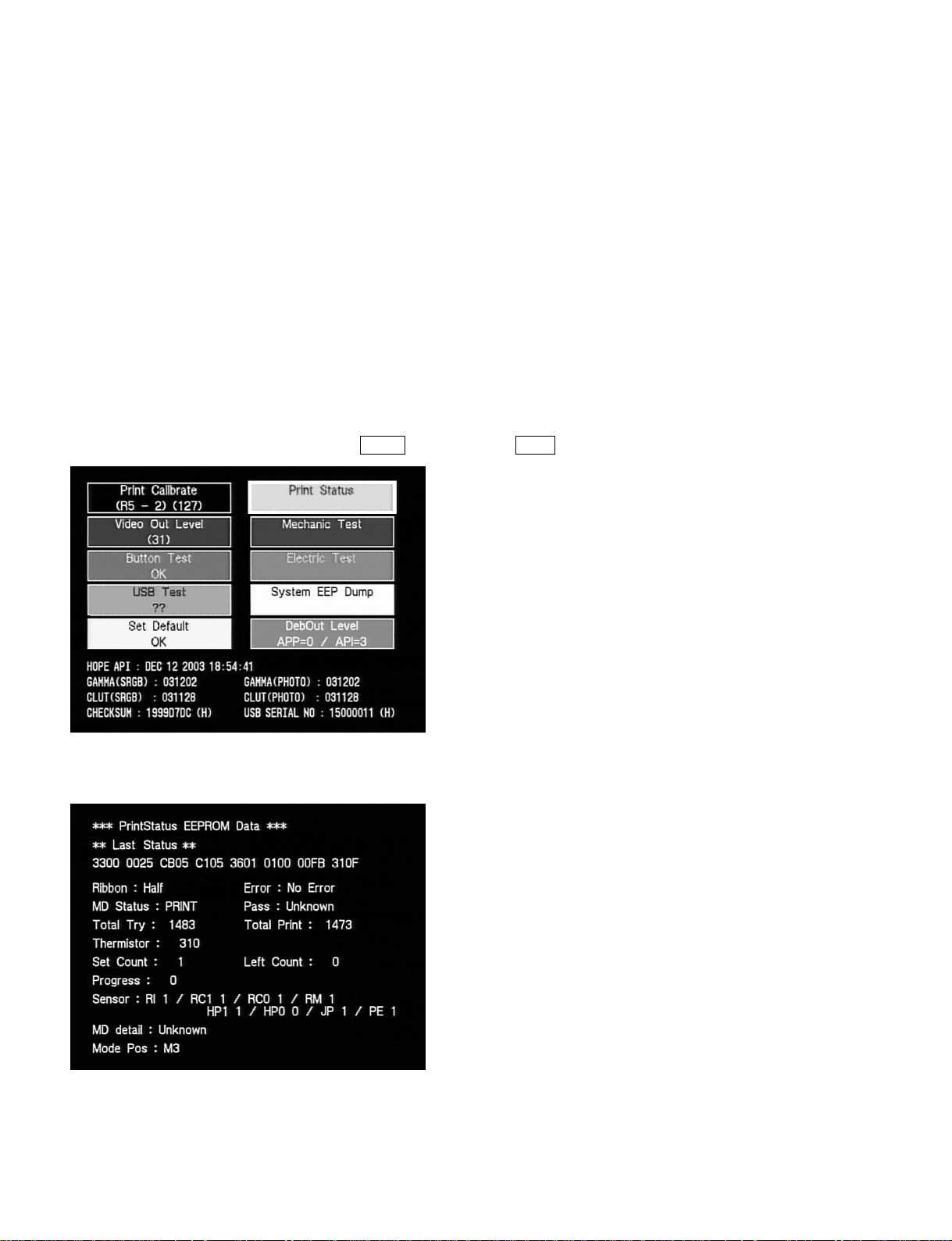
In this unit, the “status of printer” and “status of last 10 errors” are displayed and confirmed in the service
mode.
Activation
1. Start the service mode. (Refer to Section 3-2.)
2. Shift the frame to “Print Status” using the Arrow key and press the Enter key.
(Screen 4-1)
The “Status display” screen is displayed on the color monitor.
(Screen 4-2)
4-2
DPP-EX50 V1
Page 41

Viewing the screen
Red characters: Status display
** Last Status **: Status of previous printing
** Current Status **: Present status
** Error 0 **: Status of last error
** Error 1 **: Status of error occurred two times earlier
** Error 9 **: Status of error occurred ten times earlier
When the error occurred in the past, “** Error 0 **” is displayed on the first status screen.
If the Arrow key (←) is pressed in “** Error 0 **”, “** Last Status **” is displayed.
When no error occurred in the past, “** Last Status **” is displayed on the first status screen.
If the Arrow key (←) is pressed in “** Last Status **”, “** Current Status **” is displayed.
Ribbon: Ribbon display
None: Ribbon is not set.
Post: Cartridge for post card size is inserted.
L: Cartridge for L size is inserted.
Half: Cartridge for small size is inserted.
Cleaning: Cartridge for cleaning is inserted.
Unknown: Not known
(Last 10 errors are stored.)
Arrow key (→): Displays error record just before
Arrow key (←): Displays error record just after
Error: Error type
No Error: No error
No Ribbon: No ribbon
Ribbon End: Ribbon end
Ribbon Error: Ribbon error
Paper End: No paper
Paper Long: Paper length error (Long)
Paper Short: Paper length error (Short)
Paper Exist: Remaining paper
PE Error: PE sensor error
Head Error: Thermal head error
MMotor Error: DC motor error
SMotor Error: Stepping motor error
Mode Error: Mode transition error
HeatStrage Error: Heat storage correction error
Other Error: Other error
Unknown: Not known
MD Status: Mechanical deck status
IDLE: Idle state
INIT: During mechanical reset
PRINT: During printing
TEST: During testing (Printing in the service mode, etc.)
Unknown: Not known
DPP-EX50 V1
4-3
Page 42

Pass: Print pass
Feed: During paper feeding
Y: During yellow printing
M: During magenta printing
C: During cyan printing
Lami: During laminate printing
Unknown: Not known
Total Try: Total count of tried printing
Total Print: Total count of printing
Thermistor: Thermistor value of thermal head
Set Count: User setting count (1 or 0)
Left Count: Remaining printing count (1 or 0)
Progress: Progress (%) of each color (Y. M. C and L) during printing
Sensor: Each sensor value (1 or 0)
MD detail: Details of mechanical deck state
Idle: Idle state
Ribbon Init1: Ribbon initial point 1 (Detection of the first ribbon mark of Y)
Ribbon Init2: Ribbon initial point 2 (Detection of ribbon mark other than Y)
Ribbon Init3: Ribbon initial point 3 (Halfway of ribbon)
Ribbon Init4: Ribbon initial point 4 (Detection of the second ribbon mark of Y)
Preheat: Preheat (Increasing thermal head temperature)
Cooldown: Cool down (Decreasing thermal head temperature)
Paper Sup: Paper feeding
Paper Rev1: Paper reverse 1(After paper feeding, reverse the paper to the point
of paper end while determining the paper length.)
Paper Rev2: Paper reverse 2 (Reverse paper after single color printing)
Paper Int0: Paper initial point 0
Paper Int1: Paper initial point 1
Print: Printing
Paper Eject1: Paper eject 1 (Paper eject at the completion of printing)
Paper Error Eject0: Paper error eject 0
Paper Error Eject1: Paper error eject 1
Timeout M0/1: Return to M0 or M1
Unknown: Not known
Mode Pos: Thermal head position
M0
M0.2
M0.3
M0.5
M1
M2
M2.4
M3
M3.1
M3.2
M4
M5
Unknown: Not known
4-4
DPP-EX50 V1
Page 43

4-3. Upgrade
n
Download the latest firmware and technical memo from the homepage of GPS.
4-3-1. Firmware
The firmware of DPP-EX50 is stored in IC102 (flash memory) on the DK-44 board. The firmware can be
upgraded using a Memory Stick or Compact Flash Card by employing flash memory for program storage
memory.
4-3-2. Upgrade
Upgrade when requiring the improvement in a function (the version of firmware).
m
Be sure to upgrade the firmware (latest firmware) in the following cases.
. When replacing the DK-46 board
. When replacing IC102 on the DK-46 board
Upgrading
1. Download the latest firmware (hereafter referred to as firmware) from the GPS homepage.
2. Copy the firmware (downloaded and extracted folder) to the route directory of a Memory Stick or
Compact Flash Card.
3. Insert the Memory Stick or Compact Flash Card into the Memory Stick slot or Compact Flash Card
slot of this unit.
4. Insert the power cord of this unit into the receptacle. (Power LED is lit in red.)
5. Press the Power key while pressing the Menu and Print keys simultaneously.
6. Release all keys when the buzzer “beeps” and “access” LED (beside the Memory Stick slot) blinks.
7. Confirm that the “TV OUT” LED blinks. (Completion of upgrade)
8. Disconnect the power cord from the receptacle and remove the Memory Stick or Compact Flash Card
from this unit.
9. Insert the power cord of this unit into the receptacle, and connect the color monitor to the VIDEO
OUT connector of this unit using the video cable.
10. Press the Power key while pressing the Menu key and Enter key. (Service mode is activated.)
11. Release all keys when the initial screen (screen 4-3) of service mode is displayed on the color
monitor.
12. Confirm that the “CHECKSUM” value displayed in the lower left of the screen is the same as the
technical memo value.
n
The “CHECKSUM” value displayed on the screen 4-3 is an example. It varies depending on models.
13. Press the Cancel key to return the display to the initial screen.
14. Turn off the power and disconnect the power cord from the receptacle.
DPP-EX50 V1
4-5
Page 44
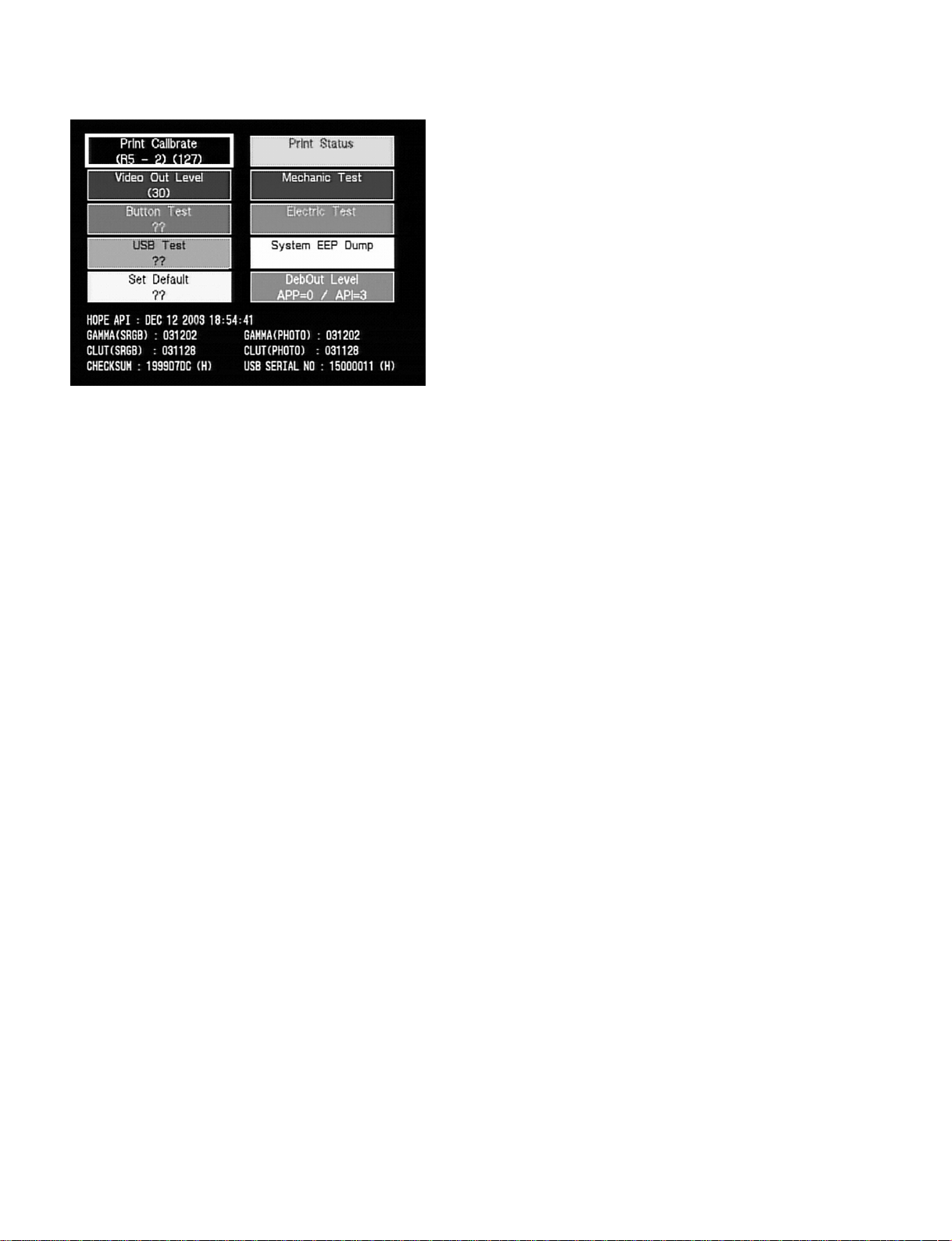
(Screen 4-3)
4-4. Mechanical Troubleshooting
The troubles caused by a mechanical deck can be mainly classified into the following.
1. Any paper cannot be fed normally. (Paper feed/eject trouble)
2. Any ink ribbon cannot be fed normally. (Ribbon trouble)
3. Printing cannot be performed normally. (Print trouble)
The cause and remedy of each trouble are described below.
1. Paper feed/eject trouble
Trouble: . No paper is ejected from the paper feed tray.
. Paper is ejected from the paper feed tray, but it stops halfway.
Cause: Perform the mode transition operation in “Mechanic Test” (refer to Section 3-7.) in the
service mode and confirm whether the UP plate operation is normal.
Normal: The chassis assembly is abnormal.
Abnormal: The paper feed block (K (paper feed) frame assembly) is abnormal.
Remedy: . Clean (wipe with dry cloth) if the paper feed roller and separation roller are dirty due to an
abnormal paper feed block.
. Replace the K (paper feed) frame assembly if the paper feed roller and separation roller are
not dirty.
. Replace the chassis assembly if it is abnormal (the mode gear is damaged).
Trouble: . Paper is fed normally, but it is ejected as blank paper.
. Multiple sheets of paper are fed continuously. (Multiple paper feed)
Cause: Incorrect paper detection.
Remedy: . Confirm the fixing state of the PE-46 and JD-46 boards. Replace the PE-46 and JD-46
boards if the state is normal.
4-6
DPP-EX50 V1
Page 45

Trouble: Paper is folded inside a printer and cannot be taken out. (Paper jamming)
Cause: . Abnormal ribbon cassette.
. Abnormal paper feed block. (e.g., Separation plate deformation and damage)
Remedy: . Remove the mechanical deck block from the lower cabinet and eliminate the paper.
. Replace the K (paper feed) frame assembly if the paper feed block is abnormal.
n
The ribbon cassette is judged to be abnormal when no abnormality is detected in a paper feed
block. Confirm the ribbon cassette. (e.g., Ribbon rewind, counter wind and ribbon cassette
deformation)
2. Ribbon trouble
Trouble: The ribbon is wound round the capstan roller and cannot be taken out. (Ribbon jamming)
Cause: . Abnormal ribbon cassette
. Abnormal installation position of ribbon guide
. Abnormal chassis assembly (Deterioration in take-up reel clutch torque or ribbon path
abnormality due to chassis deformation)
Remedy: . Remove the mechanical deck block from the lower cabinet, turn the gear engaged with the
stepping motor gear, and eliminate the ribbon.
. Confirm that the ribbon guide is fixed in clockwise direction with the heat sink and in the
non-floating state.
(If the ribbon guide is not fixed in the conditions above)
Loosen the fixing screw and fix the ribbon guide again.
. Replace the chassis assembly if it is abnormal.
3. Print trouble
Trouble: . Paper is not fed from the paper feed tray.
. Abnormality is detected at equal pitch intervals in the paper feed direction of the printed
side.
n
An abnormal point can be confirmed according to the interval of a pitch.
. Pitch interval of 18.8 mm: Pinch roller abnormality
. Pitch interval of 20.4 mm: Capstan roller abnormality
. Pitch interval of 37.7 mm: Platen roller abnormality
Cause: . Adhesion of dust or grease
. Adhesion defect (in case of a pinch roller and platen roller)
Remedy: . Remove the mechanical deck block from the lower cabinet and clean each roller. (For the
dust adhering to the capstan roller, eliminate it using a gum tape.)
Trouble: A stripe is detected in the paper feed direction of the printed side.
Cause: . Adhension of foreign objects to the thermal head surface
. Broken thermal head
. Flaw and scar on ribbon guide
. Flaw and burr on the printed side of paper path of K (paper feed) frame assembly
Remedy: Clean the paper feed path using the cleaning kit supplied with this unit. When the trouble
persists even after cleaning, replace other faulty parts that may cause the trouble.
DPP-EX50 V1
4-7
Page 46

Page 47

SAFETY CHECK-OUT
After correcting the original service problem,
perform the following safety checks before
releasing the set to the customer :
Check the metal trim, “metallized” knobs, screws,
and all other exposed metal parts for AC
leakage. Check leakage as described below.
LEAKAGE TEST
The AC leakage from any exposed metal part to
earth ground and from all exposed metal parts to
any exposed metal part having a return to
chassis, must not exceed 3.5 mA. Leakage
current can be measured by any one of three
methods.
1. A commercial leakage tester, such as the
Simpson 229 or RCA WT-540A. Follow the
manufacturers’ instructions to use these
instruments.
2. A battery-operated AC milliammeter. The
Data Precision 245 digital multimeter is
suitable for this job.
3. Measuring the voltage drop across a resistor
by means of a VOM or battery-operated AC
voltmeter. The “limit” indication is 5.25 V, so
analog meters must have an accurate lowvoltage scale. The Simpson 250 and Sanwa
SH-63Trd are examples of a passive VOM
that is suitable. Nearly all battery operated
digital multimeters that have a 20 V AC range
are suitable. (See Fig. A)
DPP-EX50 V1
To Exposed Metal
Parts on Set
0.15 µF 1.5 k
Fig A. Using an AC voltmeter to check AC leakage.
Z
Earth Ground
AC
voltmeter
(5.25V)
Page 48

DPP-EX50 (UC,CE,KR,CN,AU) E
9-955-452-11
Printed in Japan
Sony Corporation 2004. 2 22
B&P Company ©2004
 Loading...