

LVO FL14 Operators Manual
LVO Manufacturing, Inc.
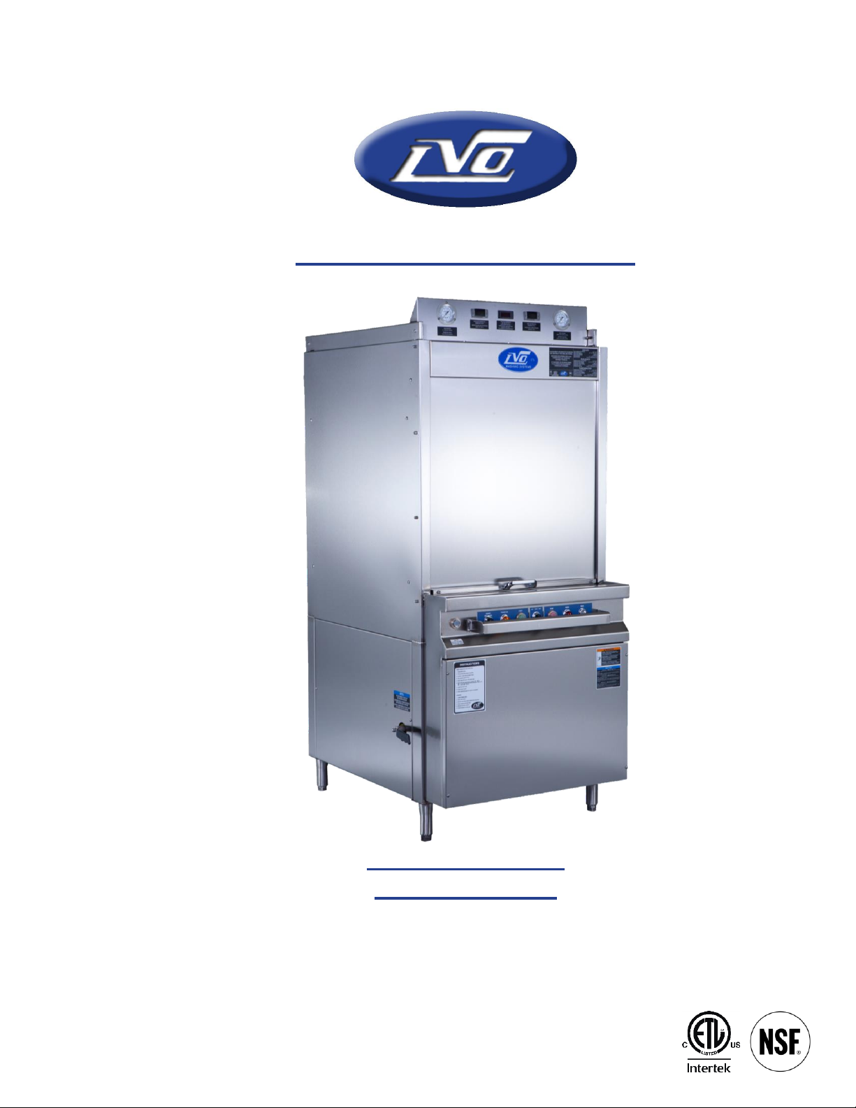
FL14 Pan-Washer
Owner’s Manual

LVO Manufacturing, Inc.
808 N. 2
Rock Rapids, IA 51246
www.lvomfg.com
(712) 472-3734
__________________________________________________________________________________________________________________________________________________________________
Warranty
LVO Manufacturing Inc. warrants equipment manufactured by it to be free from defects in
material and workmanship for a period of one (1) year from date of delivery except as noted below.
LVO will not be held responsible for damage or unsatisfactory performance due to negligence,
accident, alteration, unauthorized repair, improper installation or startup (see owner’s manual),
improper application, or improper maintenance (see owner’s manual).
Parts found, on factory inspection, to be defective in workmanship or materials during the
warranty period will be replaced (parts and labor, not overtime), provided the Buyer returns the
defective parts to LVO Manufacturing Inc. within 30 days, transportation prepaid. LVO
Manufacturing Inc. will pay UPS 2nd Day Air shipping charges for parts (with the exception of
excessively large or heavy items) covered on warranty if the machine is not operational.
LVO Manufacturing Inc. reserves the right to make changes in design and construction of its
products without imposing any obligation upon itself toward products previously manufactured.
This warranty is in lieu of any other warranties, expressed or implied, made on the part of
LVO Manufacturing Inc. who does not accept responsibility to any purchaser of its products for any
representation or warranty made by dealers or salespersons beyond those herein expressed including
any implied warranties of merchantability or fitness for a particular purpose.
nd
Avenue E., P.O. Box 188
1-800-346-5749 Fax (712) 472-2203
Warranty Procedure
1) Locate and record the 12 digit serial number located on the upper left-hand side of the pan washer.
2) Gather as much information about the problem as possible.
3) Call LVO Manufacturing Inc. at 1-800-346-5749 and request
technical service. Prior to performing any warranty work, you must
call the factory for a warranty authorization number (WA-____). This
warranty authorization number must be on every invoice we receive for
services rendered on the machine. Without this authorization number
the invoice will not be paid. The warranty number must also be
included with the defective part returned.
2

LVO Manufacturing, Inc.
808 N. 2
Rock Rapids, IA 51246
www.lvomfg.com
(712) 472-3734
__________________________________________________________________________________________________________________________________________________________________
Table of Contents
Warranty ................................................................................................................................................... 2
Table of Contents ..................................................................................................................................... 3
FL14 Specifications ................................................................................................................................. 4
Electrical Data .......................................................................................................................................... 5
Warnings & Cautions ............................................................................................................................... 6
Introduction .............................................................................................................................................. 7
Installation Instructions ............................................................................................................................ 8
Startup Procedures ................................................................................................................................. 11
Sequence of Operation ........................................................................................................................... 13
Operation of Machine ............................................................................................................................ 14
Preventative Maintenance ...................................................................................................................... 17
Trouble Shooting – Electric Machines ................................................................................................... 18
Trouble Shooting – Gas Machines ......................................................................................................... 19
Trouble Shooting – Steam Machines ..................................................................................................... 19
Trouble Shooting Flowchart .................................................................................................................. 20
Parts List ................................................................................................................................................ 22
Drawings:
(Drawing scales are approximate)
General View ......................................................................................................................................... 26
Four View – Electric .............................................................................................................................. 27
Four View – Gas .................................................................................................................................... 28
Door Weight & Cable Assembly ........................................................................................................... 29
Bun Pan Rack ......................................................................................................................................... 30
Cake Pan Rack ....................................................................................................................................... 31
Hold-Down Rack ................................................................................................................................... 32
Ladder Diagram – Electric ..................................................................................................................... 33
Ladder Diagram – Gas ........................................................................................................................... 34
nd
Avenue E., P.O. Box 188
1-800-346-5749 Fax (712) 472-2203
3

LVO Manufacturing, Inc.
808 N. 2
Rock Rapids, IA 51246
www.lvomfg.com
(712) 472-3734
__________________________________________________________________________________________________________________________________________________________________
FL14 Specifications
Overall Dimensions
Width – 36” Depth – 53” (54 ¾” Gas)
Height – 84 ¾” Height with door open – 106”
Door opening – 32” wide x 30” high
Hot Water System
½” hot water supply required, union provided
140°F water required at the machine
78 GPH at 20 PSI (6 ½ gal/cycle x 12 cycle/hr)
Rinse booster: (1) 9 kW heating element in a 9 ½ gallon rinse tank OR
½” steam coil in a 9 ½ gallon rinse tank (Recirculating Steam Only)
Full Load Amps
208 Volt 230 Volt 460 Volt
Electric 79.1 71.5 36.8
Gas/Injected Steam 54.1 48.9 25.5
Recirculating Steam 29.1 26.3 14.2
Gas System (Gas Machines Only)
½” gas supply
Natural: 7” W.C. minimum inlet, 6” W.C. main manifold – 48,000 BTU
Propane: 11” W.C. minimum inlet, 10” W.C. main manifold – 46,000 BTU
3” stainless steel chimney on back of machine
Steam System (Steam Models Only)
¾” steam line, 10-15 PSI 23 lbs/hr average – Injected
43 lbs/hr average – Recirculating
Wash System
10 Hp pump recirculates approximately 180 GPM @ 55 PSI
Heat: Electric – (1) 9 kW heating element
Gas – (2) 24,000 BTU rated infrared burners – 48,000 BTU total
Injected & Recirculating Steam – 10 to 15 PSI, 23 lbs/hr average
40 gallon wash tank
1 ½” copper drain
6” steam exhaust vent companion flange
(Requires PVC, CPVC, or stainless steel field installed duct)
nd
Avenue E., P.O. Box 188
1-800-346-5749 Fax (712) 472-2203
4

LVO Manufacturing, Inc.
808 N. 2
Rock Rapids, IA 51246
www.lvomfg.com
(712) 472-3734
__________________________________________________________________________________________________________________________________________________________________
Electrical Data
Electrical Data for models FL14, PT14, FL25, & PT25 – Electric
208 Volt 230 Volt 460 Volt
Pump Motor 27.1 24.3 12.2
Control Circuit 2.0 2.0 2.0
Wash Heater (one 9 kW) 25.0 22.6 11.3
Rinse Heater (one 9 kW) 25.0 22.6 11.3
Total Running Current 79.1 71.5 36.8
Electrical Data for models FL14, PT14, FL25, & PT25 – Gas or Injected Steam
208 Volt 230 Volt 460 Volt
Pump Motor 27.1 24.3 12.2
Control Circuit 2.0 2.0 2.0
Rinse Heater (one 9 kW) 25.0 22.6 11.3
Total Running Current 54.1 48.9 25.5
Electrical Data for models FL14, PT14, FL25, & PT25 – Recirculating Steam
208 Volt 230 Volt 460 Volt
Pump Motor 27.1 24.3 12.2
Control Circuit 2.0 2.0 2.0
Total Running Current 29.1 26.3 14.2
Electrical Supply to the machine should exceed the figures by the amount required by local codes.
Note: Changing the voltage of the machine in the field requires different heating elements. Contact
the factory if this situation arises.
nd
Avenue E., P.O. Box 188
1-800-346-5749 Fax (712) 472-2203
5
LVO Manufacturing, Inc.
WARNING: IF YOU SMELL GAS, SHUT OFF THE GAS SUPPLY TO THE
APPLIANCE, EXTINGUISH ANY OPEN FLAME, AND TEST ALL JOINTS WITH A
SOAP SOLUTION. IF ODOR PERSISTS, CALL YOUR GAS SUPPLIER
IMMEDIATELY.
AVERTISSEMENT: SI UNE ODEUR DE GAZ EST DÉCELÉE, COUPER
L’ALIMENTATION EN GAZ DE L’APPAREIL, ÉTEINDRE TOUTES LES FLAMMES
ET VÉRIFIER TOUS LES RACCORDS À L’AIDE D’UNE SOLUTION SAVONNEUSE.
SI L’ODEUR PERSISTE, AVERTIR IMMÉDIATEMENT LE FOURNISSEUR DE GAZ.
FOR YOUR SAFETY: DO NOT STORE OR USE GASOLINE OR OTHER
FLAMMABLE VAPORS OR LIQUIDS IN THE VICINITY OF THIS OR ANY OTHER
APPLIANCE.
808 N. 2
Rock Rapids, IA 51246
www.lvomfg.com
(712) 472-3734
__________________________________________________________________________________________________________________________________________________________________
Warnings & Cautions
General Warnings and Cautions:
1. Service work on the machine should be done by either a factory representative or qualified local
service company. Contact the factory if the machine is under warranty.
2. Failure to follow the cleaning guidelines described in this manual will damage the machine and
will void the warranty.
Gas Model Warnings and Cautions:
1. Installation must conform to local codes and the National Fuel Gas Code, ANSI Z223.1.
In Canada: Installation must be in accordance with CGA Standard CAN/CGA-B149.1, Natural Gas
Installation Code or CAN/CGA-B149.2, Propane Installation Code.
nd
Avenue E., P.O. Box 188
1-800-346-5749 Fax (712) 472-2203
2. Instructions should also be posted in a prominent location describing what to do in the event that
the smell of gas is detected in the vicinity of the machine. (This information can be obtained from
your local gas supplier).
3. Do not obstruct the flow of ventilation and combustion air to the machine.
4. Gas model pan washers are equipped with an electronic ignition that automatically lights the
burners when the power switch is turned to the “ON” position and there is enough water in the
machine. To shut the burners off, the power switch should be turned to the “OFF” position.
6

LVO Manufacturing, Inc.
808 N. 2
Rock Rapids, IA 51246
www.lvomfg.com
(712) 472-3734
__________________________________________________________________________________________________________________________________________________________________
Introduction
This manual should be read and understood by everyone involved with the installation and operation
of the pan washer. Keep this manual in a safe place for future reference. Extra copies or replacement
copies can be purchased from the manufacturer.
Service work on the machine should be done by either a factory representative or qualified local
service company. Contact the factory if the machine is under warranty.
The LVO pan washer is designed for use in bakeries, restaurants, schools, hospitals, and hotels, to
clean pots, pans, bowls, and utensils. LVO pan washers are constructed of 14 gauge stainless steel
(cabinets) and 12 gauge stainless steel (framework). The interior piping, rinse system, wash arms, and
screens are stainless steel. Because of its sturdy construction, it will deliver years of powerful,
thorough cleaning.
The machine is equipped with a heating element in the rinse tank to boost the rinse water to a
sanitizing 180°F at the inlet to the machine. A rinse tank heated with recirculated steam is an option
available on some models.
The wash tank on electric models incorporates a 9 kW electric heating element for heating the wash
water. The gas models use a series of (2) 24,000 BTU infrared burners. Steam models use either a
direct injection system or a recirculated steam heating coil.
The pump recirculates wash water at approximately 55 pounds per square inch of pressure.
Each machine is equipped with two safety switches. The first is a low water cut-off, which shuts the
machine off when the water level in the wash tank falls below the required level. The other safety
device is a door switch, which prevents the machine from operating when the door is not completely
closed. An electrical schematic for your machine is posted inside the control box cover.
Detergent Feeders
This machine must be operated with an automatic detergent feeder, which is supplied by the customer,
including a visual means to verify that detergent is delivered or a visual or audible alarm to signal that
detergent is not available for delivery. Power for the feeder can be provided by the pump supply
connection in the control panel. See feeder equipment manual for additional information.
nd
Avenue E., P.O. Box 188
1-800-346-5749 Fax (712) 472-2203
7
LVO Manufacturing, Inc.
808 N. 2
Rock Rapids, IA 51246
www.lvomfg.com
(712) 472-3734
__________________________________________________________________________________________________________________________________________________________________
Installation Instructions
Step 1 READ: Read and understand these instructions thoroughly before attempting any part of the
installation process.
WARNING: Not following these instructions may void warranty, cause
damage to the equipment and/or cause injury to anyone involved in the
installation or operation of this machine.
A copy of the installation instructions and start-up procedure is printed on the sheet attached to
the side of the machine. EVERYONE involved with the installation must be familiar with all
aspects of the installation procedure.
Step 2 POSITIONING: The factory recommends leaving as much room as possible around the
machine for future service work. No less than 16” should be allowed along the sides of the
machine (36” for side with control box), and no less than 12” between the rear of the machine
and the wall. Extra room around the machine will facilitate cleaning the washer area.
Step 3 UNCRATING: Leave the machine fully crated until the washer is placed in the location
where it is to be installed. After the washer is uncrated, remove the banding that holds the
door weight stationary on the back of the machine. This will allow the door to open. Inside
you will find the accessories for the machine. Among these will be the fan (if ordered) and the
legs. Remove the machine from the pallet, install the legs, and level the machine. The legs are
adjustable by turning the small end one way or the other.
Step 4 DRAIN: Provisions for the drain should be made next. The pan washer has a copper drain
located as shown on the drawings (see specifications page for drain size). The drain should be
plumbed according to local code. Local ordinance may require a grease trap, vent, and/or a
floor sink. If required, these should be installed before the machine is installed. It is strongly
recommended that unions be used to allow the machine to be easily moved. Failure to do so
may void the warranty.
Step 5 WATER SUPPLY HOOK-UP: The factory recommends 140°F hot water at the machine
(see specifications page for water line size). This may require a dedicated water heater for the
pan washer. If hard water is present, the manufacturer recommends installing a water softener
or calcium filter. Hard water deposits will shorten the life of many of the components on the
pan washer, resulting in higher maintenance costs. Please note that a union is installed at the
point of hook-up (see drawings). This will allow the machine to be moved for service and
cleaning. The customer must furnish a shut-off valve on the supply side of the union. This
8
nd
Avenue E., P.O. Box 188
1-800-346-5749 Fax (712) 472-2203

LVO Manufacturing, Inc.
808 N. 2
Rock Rapids, IA 51246
www.lvomfg.com
(712) 472-3734
__________________________________________________________________________________________________________________________________________________________________
shut-off should be easily accessible to the operator of the machine. Additionally, if the
machine is located a long distance from the water main, it may be necessary to supply a larger
line to the machine to insure proper water pressure and flow for the machine to operate
correctly.
Step 6 STEAM VENT: The machine is equipped with a collar for 6” duct work as shown on the
drawings. This duct should be directly vented to the outside of the building. DO NOT vent
into a wall, attic, or any other concealed space of the building, and avoid horizontal runs of
duct.
The factory recommends 6” plastic pipe or stainless steel duct for the vent. If stainless steel is
used, the duct work should be installed with reverse joints so that the condensate inside the
vent can drain back into the machine without leaking, and all seams should be sealed with
silicone sealant.
Generally, the machine will ship with fractional hp inline fan option. This fan should be
mounted and sealed with silicone directly into the two adapters sent with the fan with the side
with the fan blade pointing up, and the adapter into the flange on the top of the machine before
the ductwork is installed. The longer 12” adaptor should be placed between the machine and
the fan, with the shorter 3” adaptor placed into the discharge side of the fan. The fan is
powered from the control circuit. Wire is provided to connect the fan to the two terminals
marked “FAN”
The fan is designed to run at two different speeds. The lower speed is to remove excess steam
from the machine during the wash cycle, which is determined by the speed control located
inside the panel. The speed control should be set so that it just removes any steam coming
from around the door when the machine is running fully loaded. The higher speed is
controlled by a timer and runs at the end of each cycle and when the door to the machine is
open.
Note: Consult the factory before connecting any fan not supplied with the machine.
While the machine is designed to be directly connected to a vent, local or state codes may
require a hood to be installed. Always check the local regulations prior to installing the vent.
Step 7 ELECTRICAL CONNECTIONS: The electrical connection to the machine should be made
by a qualified electrician. All steps should be taken to insure that the supply voltage to the
machine is the same as the rated voltage of the machine. Also, check that sufficient amperage
is supplied to the machine (see specifications page for ratings).
nd
Avenue E., P.O. Box 188
1-800-346-5749 Fax (712) 472-2203
9

LVO Manufacturing, Inc.
808 N. 2
Rock Rapids, IA 51246
www.lvomfg.com
(712) 472-3734
__________________________________________________________________________________________________________________________________________________________________
A main power shut-off, supplied by the customer, must be installed near the machine in a
place easily accessible by anyone operating or servicing the machine. The line from the main
shut-off to the machine should be watertight flex conduit. The factory strongly recommends
that a few extra feet be used to allow the machine to be moved if necessary. The wire used to
supply the machine must be heavy enough to carry the amperage load of the machine. The
supply should be run into the back of the machine at the bottom, between the rinse tank and
the side of the machine, and through the back of the control box.
The first connection should be the main ground to the grounding lug at the lower right hand
corner of the control panel. Next, the hook-up can be made to the main power block.
Once the hook-up is complete, the circuit breakers in the control box of the washer must be
checked to make sure they are in the “OFF” position. The main switch on the wall can then be
turned on to power the machine.
Step 8 GAS CONNECTION (Gas Machines Only): A certified gas technician is required for the
hook-up and final adjustments of the burners. This is necessary to insure proper inlet and
manifold pressure for the gas machines (see spec page for gas pressure settings).
Verify the type of gas supply to be used, either natural or LP, and make sure the marking on
the gas data plate agrees with that of the supply. The gas line hook-up must be made with a
union at the location shown on the gas machine drawing (see spec page for gas line size). This
line must have a shut-off valve (supplied by the customer) installed near the machine and
accessible by anyone operating or servicing the machine.
A 3” stainless steel gas chimney runs up the back of the machine. A draft diverter is included
with the machine (shipped inside the machine with the other accessories). The draft diverter
must be installed on top of the factory installed chimney. The Type B gas flue can then be
continued to the outside of the building per local codes.
The initial start-up of the burners should not be done until the start-up procedures for the
machine on the following pages have been completed.
Step 9 STEAM CONNECTION (Steam Machines Only): A steam line is required to supply the
steam injector or recirculated steam heat exchanger coil (see spec page for size of steam line).
A strainer is already built into the machine but a union will be required in the supply line
(supplied by the customer). The specification sheet above lists the rated pressure and average
steam consumption rate for the machine.
nd
Avenue E., P.O. Box 188
1-800-346-5749 Fax (712) 472-2203
10

LVO Manufacturing, Inc.
808 N. 2
Rock Rapids, IA 51246
www.lvomfg.com
(712) 472-3734
__________________________________________________________________________________________________________________________________________________________________
Startup Procedures
Warning: These instructions must be followed or damage to the machine will result.
Step 1: Close drain valve. See drawings for location.
Step 2: With the circuit breakers in the control panel of the machine in the “OFF” position and the
main power supply to the machine connected, the ON-OFF switch on the button panel can
be turned to the “ON” position. Then wait approximately 5 seconds for the machine
controller to power up.
Note: The amber power light will not turn on until there is sufficient water in the machine.
Step 3: Fill the machine by pressing the Auto Fill button. The machine will continue to fill for 90
seconds past the point where the low water protection device is energized, turning on the
power light and temperature controllers. The machine is equipped with a low water
protection device and will not run without sufficient water in the wash tank.
Note: The machine has a door switch and will not operate with the door partially open.
Step 4: With the machine full of water and with the door closed, press the start button and let the
machine go through a complete cycle. The timers in the control panel will go through their
sequence, lighting the wash and rinse lights on the front of the machine. The cycle is
complete when the red light goes off and the amber light stays on. The pump will not run at
this time because the pump circuit breaker in the control panel is in the “OFF” position.
Step 5: Repeat Step 4 at least two times or until water can be heard spraying out of the rinse nozzles.
This ensures that the rinse tank is full of water before the heating element is energized.
Step 6: All circuit breakers in the control panel can now be switched to the “ON” position. This will
energize the heating system in the wash and rinse tanks.
Step 7: Check the pump for proper rotation by pressing the start button and observing the wash
pressure gauge on the front of the machine for 5 to 10 seconds. Then press the stop button.
The wash pressure should be 45-60 psi. If the pressure is erratic and only rises to about 20
psi, the pump is running backwards. The pump will also have a noticeable growl when
running backwards. Disconnect power to the machine and reverse the outside two wires that
feed the power block in the control panel. Reconnect power and run the pump again to
confirm that it is operating correctly.
nd
Avenue E., P.O. Box 188
1-800-346-5749 Fax (712) 472-2203
11
 Loading...