


Owner`s Manual
VACUUM TUBE INTEGRATED AMPLIFIER
SQ-N100

2
Contents
Precautions...................................................................................................................3
Names and Functions of Parts......................................................................................4
Connections..................................................................................................................8
Connection diagram......................................................................................................9
Operation ....................................................................................................................10
SQ-N100 Block Diagram.............................................................................................11
Specifications..............................................................................................................12
Troubleshooting ..........................................................................................................13
3
Precautions
Installation location
Install this unit where good ventilation and heat radiation are
assured. Do not install where the
temperature is abnormally high
such as in direct sunlight, or
where it is dusty or humid, as this
could result in damage to this unit
despite proper heat radiation. Do
not install this unit where it will
create problems for driving the
car.
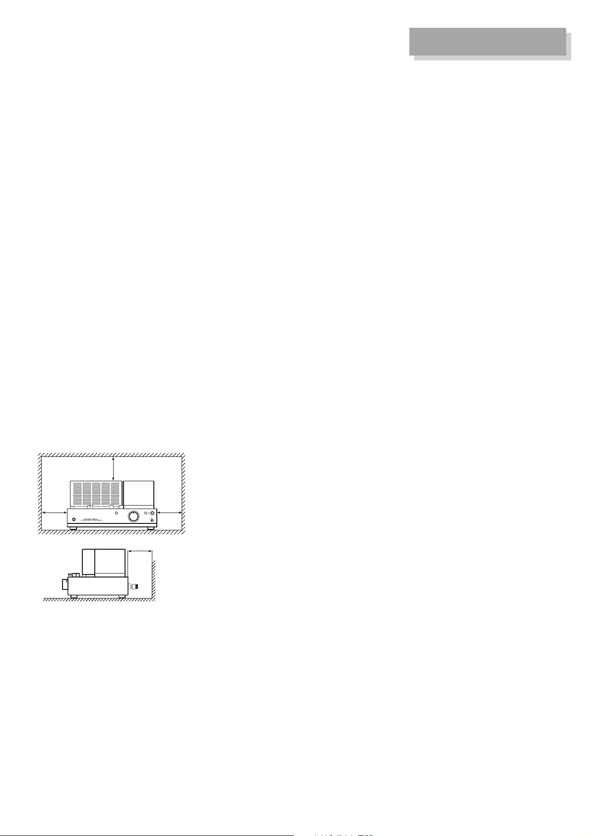
Ventilation holes
The amplifier has many vacuum
tubes, generating much heat.
Never close the ventilation holes
located on the vacuum tube cover
and the bottom plate. If the amplifier is installed on a rack or the
like, secure ample space for cooling and leave the door open. Do
not pile up other things on the
amplifier and never put articles on
it. This can cause malfunctioning.
Note:
For heat dispersal, do not install
this equipment in a confined
space such as a book case or
similar unit.
Connection with other
components
When connecting this unit with a
CD/DVD player, tuner, or another
input unit, turn off the power
switches of this unit and all other
connected units. Otherwise, a
very strong noise may be generated and destroy the speakers. In
the worst case, this can cause
equipment malfunction.
The pin-plug to be inserted in
each input terminal of this unit
shall be pushed in firmly. If the
earth side is inadequately inserted, humming and such noise may
be generated, resulting in an
adverse S/N ratio.
Cautions for speaker
connections
When making speaker system
connections, be sure not to cause
short-circuiting between ! and @
of the speaker terminals and
speaker input terminals of this
unit. If signals are applied to the
amplifier with its circuit left shortcircuited, a large current may be
carried in the output circuit and
cause malfunctioning.
The sound is not generated
shortly after the power supply
is turned on.
This amplifier is equipped with a
time muting circuit intended for
the separation of the output circuit. For this reason, no sound is
generated shortly after the power
supply is turned on.
If the volume control is moved to a
high sound level before this time
muting circuit is canceled, a large
sound is suddenly generated as a
result. We therefore advise initially
setting the volume control at a low
level. After that, you may move
the volume control to your favorite
sound level after the initial sound
has come out of the speakers.
Batteries
Caution:
Batteries used for remote controller shall not be exposed to
excessive heat such as sunshine,
fire or the like.
Repair and adjustments
When repair and adjustments are
needed, please ask the store
where you bought the unit.
Cleaning
For cleaning, use a piece of soft
cloth to wipe the unit such as
cleaning cloth available on the
market.
If the unit has become very dirty,
remove the dirt with soft cloth
absorbing a small amount of neutral detergent, and then wipe the
unit with dry cloth. Do not use a
solvent like benzine or thinner
because such a substance can
often damage the exterior.
* Note
* *
*
Wall
4
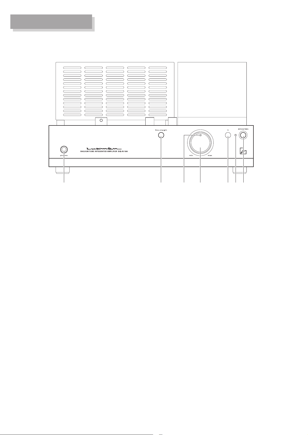
Names and Functions of Parts
1. Operation switch
(OPERATION)
This switch turns the power
supply ON/OFF. When the I/O
terminals are connected, turn
off this switch without fail.
When turning on the operation
switch again after turning it off,
wait for more than one minute.
2. Power indicator
When the operation switch is
on, this indicator is lit in yellow
to indicate that this unit is
presently energized.
3. Remote control infrared
receiver (R)
This is a sensor to receive signals from the accessory remote
control.
Do not place any objects in
front of the sensor.
4. Volume control (VOLUME)
This knob is used to adjust the
sound volume. In the position
fully turned to the left, no sound
is generated. As it is turned
clockwise, the sound volume
slowly increases.
5. Volume control indicator
This indicator is an index for the
sound level.
This indicator blinks in the middle of mute (silence) shortly
after the operation switch has
been turned ON, or when muting is performed with the
remote control.
6. Line straight switch
(line straight)
This switch is used to increase
the purity of the sound quality
by bypassing (skipping) the
tone control circuit.
7. Headphone jack (phones)
When you want to use a stereo
headphone, insert the headphone plug in this output jack.
When the plug is inserted, the
signal output to the speaker terminal is interrupted. When the
plug is pulled out, the signal
output is supplied to the speaker terminal again.
Front panel
1234567
5
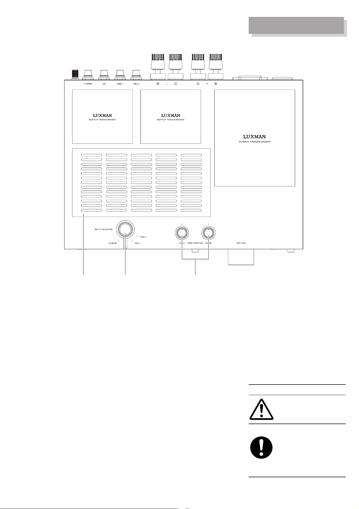
Names and Functions of Parts
8. Tone control
(TONE CONTROL, bass,
treble)
bass: This is a level control
to change the frequency characteristics in the
low-frequency range.
When it is set in the
center position, flat frequency characteristics
are obtained. Turning it
clockwise causes the
low-frequency range to
be emphasized, and
turning it counterclockwise results in attenuation.
This adjustment is
impossible while the line
straight switch is ON.
treble: This is a level control
to change the frequency characteristics in the
high-frequency range.
When it is set in the
center position, flat fre-
quency characteristics
are obtained. Turning it
clockwise causes the
high-frequency range
to be emphasized, and
turning it counterclockwise results in attenuation.
This adjustment is
impossible while the line
straight switch is ON.
9. Input selector
(INPUT SELECTOR)
This switch is used to select a
record player, CD/DVD player,
tuner, or other such component
connected to the input terminals.
There are four positions;
PHONO, CD, LINE-1, and
LINE-2. Each position corresponds to one of the input terminals on the rear panel. For
selection, adjust the knob to the
input position of your intended
playback.
This unit is an amplifier where
vacuum tubes are used. In the
state of the unit in operation, the
main body becomes hot. Be
careful not to touch it with your
bare skin. This unit should not be
used where small children are
present.
Safety cautions
Caution
Top panel
10. Vacuum tube cover
This cover is used for the protection of vacuum tubes. For
safety, this cover should be left
installed at all times.
910
8

6
Names and Functions of Parts
11. Volume control
(VOLUME,
▲, ▼)
This button is used to adjust the
sound volume. The sound volume is lowered with ▼ and
raised with ▲.
12. Mute (MUTE)
This button is used for temporary silence. When this button is
pressed to mute the sound, the
volume control indicator blinks
and the sound disappears.
When it is pressed again to stop
the muting, the sound can be
heard again.
Remote control
The remote control can be used by
pointing it at the remote control
infrared receiver of this unit. It
should be used within the range
shown in the illustration.
[Replacement of batteries]
1. Put your finger on the battery
cover claw located behind the
remote control. The battery
cover can be opened by sliding
it downwards.
2. Put the batteries (CR2025) in
the battery case, as illustrated.
3. Close the battery cover.
* When the batteries start to
lose power, the effective distance becomes shorter or the
unit does not function even
though the switch is pressed.
The batteries should be
replaced with new ones.
* If the remote control is not
used for a long time, the batteries should be removed from
the case.
Remote controller (RA-N2)
12
11
30°30°
Effective distance
about 5m

7
Names and Functions of Parts
Rear panel
13. Signal ground terminal
(SIGNAL GROUND)
This is a signal ground terminal
for equipment to be connected
to this unit. This terminal is
used to reduce noise when
other equipment is connected. It
is not for grounding for safety.
14. Phono input terminal
(PHONO)
This is an input terminal for the
connection of an analog record
player.
15. Line input terminals
(CD, LINE-1, LINE-2)
These terminals are used for
high-level signal inputs from a
CD/DVD player, SACD player,
tuner, video deck, TV audio,
and other such equipment.
These input terminals offer the
same functions.
16. Speaker output terminal
(SPEAKERS)
This terminal is used for the
connection of the speaker system. Connect the left speaker
terminal to Side L and the right
speaker terminal to Side R
according to the polarities of !
and @.
17. AC inlet (AC IN)
The accessory power cable is
connected. The power should
be obtained from a wall outlet.
When connecting
the general terminal
17
16
131415

8
Connections
Before Making Connections
Before connecting other devices,
connect the jack side of the accessory power cable to the AC inlet of
this unit.
When connecting, turn off the
power switch of this unit and the
power supplies of auxiliary devices
to prevent unexpected accidents
that may be caused by noise.
Connecting the Power Supply
Use an accessory AC power cable
and insert the AC plug in a 100V
AC outlet on the wall in the room
where the unit will be installed.
Connecting CD players, DVD
players, tuners, and other
equipment
Connect between the output terminal of a CD player or such playback equipment and the line input
terminal of this unit (CD, LINE-1,
or LINE-2) through two pin-plug
cables of R and L.
When connecting, do not confuse
the right and left connections.
Connecting a record player
Connect between the output terminal of an analog record player and
the PHONO terminal of this unit
through two pin-plug cables of R
and L.
For some types of players, the
ground wire from the phono motor
or the tone arm should be connected to the signal ground terminal of
this unit.
The phono equalizer of this unit
uses the MM cartridge.
If you use an MC cartridge or
equivalent with low output voltage,
connections should be made via a
head amplifier or a step-up transformer available as an option.
An output from an analog record
player equipped with a phono
equalizer or from an independent
phono equalizer should be applied
to the line input terminal of this unit
(CD, LINE-1, or LINE-2).
Speaker connections
Connect the right-channel speaker
to the right speaker terminal of this
unit and the left-channel speaker
to the left speaker terminal.
Correctly connect the ! terminal of
the speaker system to the speaker
terminal ! (red) of this unit and
also the @ terminal of the speaker
system to the speaker terminal @
(black) of this unit. If the ! or @
terminal is reversely connected
one side of the right or left speaker, the acoustic phases of the
sound played from the right and
left speaker systems are also
reversed. The sound level in low
range will be reduced and the
acoustic stability will worsen, thus
failing in normal stereo playback.

9
Connection diagram
CD PLAYER
RECORD PLAYER
–+– +
LR
SPEAKER SYSTEM

10
Operation
Before operation
1. Confirm that the connections
are correct. (Normal playback
cannot be achieved with wrong
connections for R, L, !, and @.)
2. Move the volume control (VOLUME) to the minimum position
at the time of power ON/OFF or
input selector changeover.
Playback procedures
1. Confirm that the volume (VOLUME) has been lowered. Press
the operation switch (OPERATION) to ON.
2. Select the playback source with
the input selector.
3. Adjust the sound level with the
volume control (VOLUME).
4. According to the playback
source, operate the tone control
or the line straight switch.
Line straight switch operation
To increase the purity of the
source selected with the input
selector, this switch is used for
playback through the shortest possible signaling route. When this
switch is turned on, the tone control circuit will be bypassed
(skipped).
Operation with tone control
function
The tone control function of this
unit comes in low (bass) and high
level controls (treble).
The low level control (bass)
changes the low acoustic range of
300Hz and lower. This circuit
secures flat frequency characteristics in the mid-position. When the
knob is turned clockwise from this
position, the low range is emphasized, while turning it counterclockwise results in attenuation.
The high level control (treble) is
used to change the high acoustic
range of 3kHz and above. Similarly
as for the low level control (bass),
this circuit secures flat frequency
characteristics in the mid-position.
When the knob is turned clockwise, the high range is emphasized, while turning it counterclockwise results in attenuation.
For both the low (bass) and high
level controls (treble), both right
and left channels are designed to
be interactive.
When the line straight switch is
turned on, this tone control does
not function.

11
SQ-N100 Block Diagram
OUTPUT TRANSFORMER
UL CONNECT
EL84ECC82ECC83
PUSH-PULL OUTPUTPHASE INVERTERPRE DRIVER
NFB
POWER AMP
SPEAKER
TERMINAL
UL
BIAS
+B1
BIAS
GND
UL
+B2
+B1
CHOKE
+B2
FOR
POWER AMP
PHONES
FOR
POWER
CONTROLLER
SUPPLY
OUTPUT
TUBE
FOR
EQ/
POWER
BIAS
ADJUST
FLAT/
TONE AMP
SUPPLY
MENT
MUTETONE AMPFLAT AMPINPUT SELECTOR SWITCHMIM PHONO
EQUALIZER AMP
LINE
STRAIGHT
TREBLE/BASS
SWITCH
RIAA
WIRELESS REMOTE CONTROL
MAIN VOLUME
POWER TRANSFORMER
HEATER
HEATER
ECC83 ECC82 ×2
EL84 ×4
OPERATION
SWITCH
FUSE
230V
0V
PHONO
CD
LINE-1
LINE-2
AC230V

12
Specifications
Rated output 12W + 12W (6Ω), 10W + 10W (8Ω, 4Ω)
Input sensitivity LINE: 150mV, PHONO (MM): 2.2mV
Input impedance 47KΩ
Frequency response 20Hz – 50KHz (within –3 dB)
Total harmonic distortion 0.3% or less (1 kHz rated output)
S/N ratio 90dB or more
Input LINE: 3, PHONO (MM): 1
Output SPEAKERS: 1
Circuiting system Mullard type UL connections
Vacuum tubes used ECC83 X 1, ECC82 X 2, EL84 X 4
Power consumption 95 W, 71 W (no signal)
Power supply AC 230V (50Hz)
Accessories Remote controller, power cable, Owner’s Manual,
Safety cautions, Coin-type battery (CR2025)
Dimensions 297W X 162H X 210 (258) D mm
(I/O terminals in brackets, including operating knobs)
Weight 11.5kg
* Design and specifications are subject to change without notice.

13
Troubleshooting
While the unit is used, an unusual phenomenon may be confused as a malfunction
for a certain reason. Prior to asking us for repair services, please check the table
below and read the instruction manual for the subsidiary devices. If the cause of the
malfunction cannot be identified, please contact your dealer.
No power is supplied even though
the power switch is
pressed ON.
• The power plug is disconnected from
the wall outlet, or it is not completely
inserted.
• The power plug is disconnected from
the AC inlet, or it is not inserted com-
pletely.
• Insert the power plug in the wall out-
let completely.
• Insert the power plug in the AC inlet
completely.
Problem
Cause
Solution
The power supply
can be turned on,
but no sound is
generated from
both right and left
channels.
• The volume control is set at the min-
imum level.
• The volume control is set at MUTE.
• The input selector is not set in the
playback source position.
• Cable connections are incomplete.
• The output level of the playback
equipment is minimum.
• Turn the volume control clockwise to
increase the sound volume.
• Cancel the MUTE mode.
• Set the input selector in the playback
source position.
• Make sure cable connections are
complete.
• Adjust the output level.
No sound comes
out on one side.
• The connecting cable is not connect-
ed on one side only.
• Make sure cable connections are
complete.
Humming sound
(boon or zzz noise)
is generated.
There is no effect of
tone control.
• The line straight switch is turned ON. • When tone control is used, the line
straight switch must be turned OFF.
• Make connections correctly so that
the ground side of the pin-plug cable
can be connected.
• Connect the ground wire of the record
player to the signal ground terminal.
• Connect (mount) the cartridge, the
shell, and the tone arm correctly.
• Provide sufficient spacing between
the power cables and the signal
cables.
• Install it distant from other devices.
• The ground side of the pin-plug cable
has no contact with the terminal.
• The ground wire of the record player
is not connected.
• Connections and mounting condi-
tions are incomplete between the
cartridge of the record player and the
shell, or between the shell and the
tone arm.
• The power cables are laid too close
to the signal cables.
• Induction noise is picked up from a
power transformer of another device.

14
MEMO

LUXMAN CORPORATION, JAPAN
AG00987C57A
 Loading...