


VACUUM TUBE STEREO POWER AMPLIFIER
MQ-300
Owner`s Manual

Contents
Precautions ············································································································· 1
Features of This Unit ································································································ 2
Names and Functions ······························································································ 4
Connections ············································································································ 6
Block Diagram ········································································································· 8
Specifications ·········································································································· 9
Before Asking for Repair Services ·········································································· 10
VACUUM TUBE STEREO POWER AMPLIFIER MQ-300
Precautions
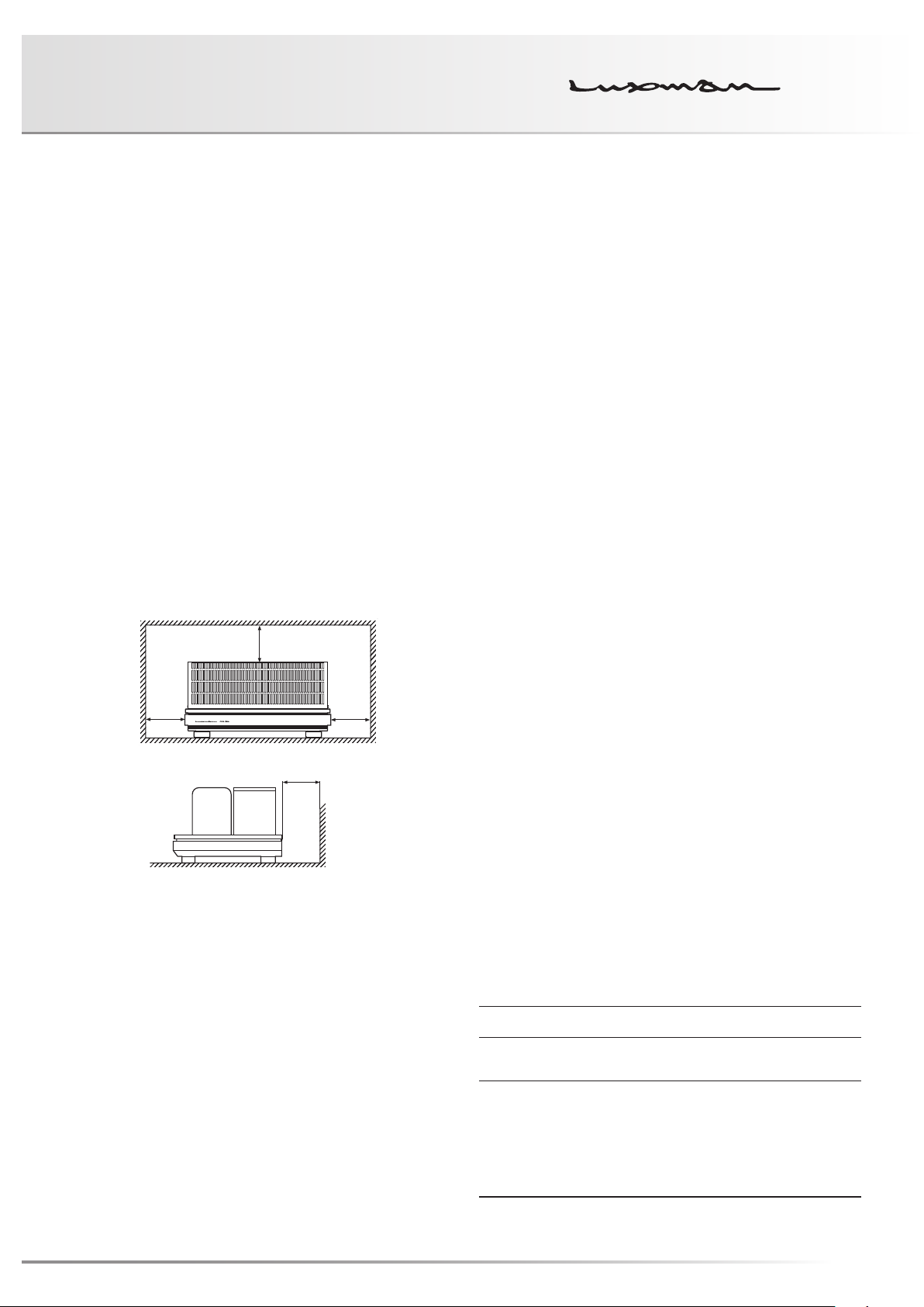
Installation place
Install this unit in a location where good ventilation and heat
radiation is assured.
Do not install it where the temperature is high such as in
direct sunlight, or where it is dusty or humid, as this could
result in damage to this unit despite proper heat radiation.
Ventilation holes
The ventilation holes on the top and bottom boards of this
product must not be blocked because this unit is a vacuum
tube amplifier and generates considerable heat. If the am-
plifier is installed on a rack or the like, secure ample space
for cooling and leave the door open. Do not pile up other
things on the amplifier and never put articles on it. Failure to
observe this may cause a malfunction.
Note:
For heat dispersal, do not install this equipment in a con-
fined space such as a book case or similar unit.
* Note
Cautions in connecting speakers
When making speaker system connections, be sure not to
cause short-circuiting between ! and @ of the speaker ter-
minals and speaker input terminals of this unit. If signals are
applied to the amplifier with its circuit left short-circuited, a
large current may be carried in the output circuit and cause
malfunctioning.
The sound is not generated shortly after
the power supply is turned on.
This product is a vacuum tube amplifier, and therefore, it
cannot deliver a sound until the vacuum tube heaters warm
up.
You can enjoy music 1 minute or more after turning on the
power. We therefore advise initially setting the volume con-
trol at a low level. After that, you may move the volume con-
trol to your favorite sound level after the initial sound comes
out of the speakers.
Repair and adjustment
When repairs and adjustments are needed, please consult
with the dealer where you bought the unit.
*
*
*
Wall
Precautions in connecting with other
components
When connecting this product to input devices such as a
control amplifier, be sure to turn off the power of this prod-
uct and all other connected devices. Otherwise, a very
strong noise may be generated and destroy the speakers.
In the worst case, this can cause equipment malfunction.
The pin-plug to be inserted in each input terminal of this
unit shall be pushed in firmly. If the grounding terminal is
inadequately connected, noises including hum may be gen-
erated, resulting in an adverse S/N ratio.
Cleaning
For cleaning, use a piece of soft cloth to wipe the unit such
as cleaning cloth. When the dirt is hard to remove, use a
small amount of neutral detergent to wipe, and then wipe
the unit with dry cloth. Do not use a solvent like benzine
or thinner because such substances can often damage the
exterior.
Safety caution
Caution
This unit is a vacuum tube power amplifier. Be careful not to
touch this product with your bare hand because this product
becomes hot in the power-on state. For safety, do not use this
product in a place where children or unchained animals are
present.
1

Features of This Unit
Circuit configuration
Direct heated triode 300B non-feedback single stereo power
amplifier
Output tube
Highly reliable Japan-made TA-300B (manufactured by
Takatsuki Electric Industry Co., Ltd.) is used as a cathode
bias circuit. The constant voltage DC-ignition method is used
for the heaters.
Voltage amplification stage
Two-stage amplification circuit with highly reliable tubes
6SN7GTB (manufactured by Tung-Sol) in parallel connection.
Rectifying tube
Two pieces of indirectly heated tubes, 5AR4 (manufactured
by Sovtec) are used in the L and R independently, whose in-
ternal impedance is low and which have excellent regulation.
Due to a gradual rise in voltage supply to the output tubes,
their lives are expected to be prolonged.
Coupling capacitor
LUXMAN’s original high sound quality oil capacitors are used.
Power transformer
The orient core EI type is used to pursue thickness and depth
in the bass range. Optimization of magnetic flux density im-
proves electrical characteristics and achieves higher sound
quality. The L-R independent structure of the secondary
winding, rectifying tubes, block capacitors, and choke coils
eliminates unwanted coloration of the sound and achieves
expressive capability with high tranquility.
Output transformer
Orient cut core carefully chosen for 300B tubes after a lot of
consideration to its sound quality and dimensional balance.
We have improved the directivity of wire rods and winding
structure and have achieved excellence in low frequency
characteristics using LUXMAN classic OY type as a basis.
2

VACUUM TUBE STEREO POWER AMPLIFIER MQ-300
Choke coil
A choke coil of FINEMET® core is equipped in the L and R
sides independently. Regular winding in which a sheet of par-
affin paper is inserted between every winding layer can de-
crease losses and achieve elaborate and fresh sound quality
with rich content.
(FINEMET® is a registered trademark of Hitachi Metals, Ltd.)
Input terminal
This product is equipped with the copper alloy input terminal
that has high conductivity equivalent to copper and hardness
equivalent to brass.
Vibration-reducing high-rigidity chassis
High-rigidity chassis structure combining a 1.6 mm thick steel
sheet with 12 mm thick aluminum top panel.
A vibration reducing structure with heat-resistant material
support at the bottoms of output tubes and rectifying tubes
lowers microphonic noise.
Appearance
This product is designed to look as graceful as possible with
special attention to the finishing touch such as transformer
cases formed by aluminum extrusion processing, specially
processed nameplates, 12 mm thick top panel with high-
grade hairline finish, and wood panel made of natural wood
with piano finish coating in a harmonic fashion.
Highly reliable design
The sound quality and tones produced by vacuum tubes have
been refined, and at the same time, both prolonged life and
highly reliable design of vacuum tubes have been achieved
by providing operating conditions of vacuum tubes with some
allowance.
Cast-iron insulator
This unit is equipped with gradation cast-iron insulators that
cuts out unnecessary external vibration and strongly supports
the weight of this unit.
Socket floating structure
The socket floating structure that minimizes the vibration in-
fluence to structurally delicate output tubes, 300B, is used to
reduce microphonic noise.
The described company names and product names are
trademarks or registered trademarks of each company.
3

Names and Functions
1 2
Front panel
Top view
1. Power indicator (OPERATION)
Turns orange when the power is turned on.
4
* This product has a bonnet on the vacuum tube section.
2. Power switch (OPERATION)
Toggles the power on and off.
When wiring or connection is performed, be sure to turn off
this switch. When turning on the power switch again after
turning the unit off, wait for more than one minute.

VACUUM TUBE STEREO POWER AMPLIFIER MQ-300
Rear panel
43 5
3. Input terminals (INPUTS)
These terminals are input terminals to connect input devices
such as a control amplifier.
Connect these terminals to an unbalanced output of an in-
put device with a pin-plug cable.
4. Speaker terminals (SPEAKERS)
These terminals are output terminals to connect a speaker
system. Connect the left speaker terminal to the L side and
the right speaker terminal to the R side according to the
polarities of ! and @.
The speaker terminals consist of @ COMMON, ! 4 Ω,
!8Ω, and ! 16 Ω for each channel. Connect the @ ter-
minal of the speaker system to the @ COMMON terminal
and ! terminal of the speaker system to ! 4 Ω, ! 8 Ω, or
! 16Ω according to the impedance of the speakers to be
used.
5. AC inlet (AC IN)
Connects the accessory power cable.
The power shall be supplied from a household wall socket.
General type
terminal
* It is possible to insert cables from below
as well as from top.
5

Connections
CONTROL AMPLIFER
CD PLAYER
CD/SACD PLAYER
RECORDER
ANALOG PLAYER
(When the speaker
impedance is 8Ω)
SPEAKER SYSTEM
+– +–
L R
6

VACUUM TUBE STEREO POWER AMPLIFIER MQ-300
Before Connecting
Before connecting other devices, connect the jack side of the
accessory power cable to the AC inlet of this unit.
Before connection is made, turn off the main power switch
of this unit and the power of all other connected devices to
prevent accidents due to noises generated unexpectedly.
How to connect power supply
Use the accessory power cable and insert the AC plug in an
outlet on the wall in the room where the unit will be installed.
How to connect the input terminals to
input devices such as a control amplifier
Connect between the output terminals of an input device
such as a control amplifier and the input terminals of this unit
with pin-plug cables.
Take extra care not to conduct wrong connection between
right and left channels. If the right and left channels are con-
nected reversely, the localization of sound images is deterio-
rated, thus failing in normal stereo playback.
How to connect speakers
Connect the left-channel speaker to the LEFT SPEAKER
terminal (L) of this unit and the right-channel speaker to the
RIGHT SPEAKER terminal (R).
Securely connect the ! terminal of the speaker system to the
red speaker terminal (! 4 Ω, ! 8 Ω, or ! 16 Ω) of this unit
according to the impedance of the speakers to be used and
the @ terminal of the speaker system to the black speaker
terminal (@ COMMON) of this unit.
If the ! and @ terminals are reversely connected to either
of the right or left of the speaker system, the signal phases
reproduced from the right and left of the speaker system are
also reversed. In such a case, be aware that the sound level
in the low range will be reduced and the acoustic stability will
worsen, thus failing in normal stereo playback.
If the impedance of the speakers to be used is other than
4Ω, 8 Ω, or 16 Ω, connect the terminal with an impedance
closest to the impedance value of the speakers.
The range of the impedance of the speaker to be connected
should be within the range of 4 Ω to 16 Ω.
7

Block Diagram
TA-300B
6SN7GTB
4Ω
8Ω
16Ω
Lch SP OUT
TRANS
OUTPUT
OIL CAPACITOR
COM
METAL CLAD RESISTOR
16Ω
Rch SP OUT
Lch B1
GND
Lch B2
8Ω
4Ω
Rch Amp
COM
Rch B1
Power Transformer
Rch B2
5AR4
Lch 6SN7GTB HEATER
REG
RECT.
Rch 6SN7GTB HEATER
REG
GND
RECT.
Lch TA-300B HEATER
REG
GND
RECT.
Rch TA-300B HEATER
FUSE
REG
Operation SW
RECT.
5AR4
6SN7GTB
OIL CAPACITOR
GND
Lch INPUT
Lch B3
Rch INPUT
GND
Rch B3
CHOKE COIL
Lch B1
Lch B3 Lch B2
GND
CHOKE COIL
Rch B1
Rch B2Rch B3
GND
8

VACUUM TUBE STEREO POWER AMPLIFIER MQ-300
Specifications
Rated output 8 W + 8 W (4 Ω, 8 Ω, 16 Ω)
Total harmonic distortion 1 % (1 kHz, 8 Ω, 1 W)
Input sensitivity 490 mV/8 W (4 Ω, 8 Ω, 16 Ω)
Input impedance 240 kΩ
S/N ratio 105 dB (IHF-A weighted, input short)
Frequency response +0.3, –1.5 dB (20 Hz to 20 kHz)
+0.3, –3.0 dB (10 Hz to 30 kHz)
Input Line: 1 system
Output Large type of speaker terminal
Supplied functions [Front panel] Power switch
[Rear panel] Input terminal, speaker terminals (4 Ω, 8 Ω, and 16 Ω), AC inlet
Circuiting system Single stereo power amplifier
Vacuum tube used 5AR4 × 2, 6SN7GTB × 4, TA-300B × 2
Accessories • Power cable
• Owner's Manual (This document)
Power source
Power consumption 190 W
Max. external dimensions 460 (W) × 237 (H) × 340 (D) mm (speaker terminals included)
Weight
* Specifications and the appearance are subject to change without notice.
230 V 〜 (50 Hz)
190 W (at no input)
29.0 kg (main unit only)
• Safety cautions
• Terminal protection cap
9

Before Asking for Repair Services
While the unit is used, an unusual phenomenon may be confused as a malfunction for a certain reason. Prior to asking our official sole
distributor of your country for repair services, please check the table below and read the operating instructions for the subsidiary devic-
es. If the cause of the malfunction cannot be identified, please contact your dealer. When we have once accepted your request for
repair services, inspection fees and traveling expenses may be claimed even though the unit is found to be normal.
Problem Cause Solution
No power is supplied even
though the power switch is
pressed ON.
No sound is generated.
(for both left and right channels)
No sound is generated on one
side.
Humming sound (boon or zzz
noise) is generated.
• The power plug is disconnected from the
wall outlet, or it is not completely inserted.
• The power plug is disconnected from the
AC inlet, or it is not inserted completely.
• Cable connections are incomplete. • Make cable connections securely.
• The output level of the playback equipment
is minimum.
• The connecting cable is not connected on
one side only.
• The ground side of the pin-plug cable has
no contact with the terminal.
• The connecting cables are too close to the
power cable.
• Induction noise is picked up from a power
transformer of another device.
• Insert the power plug in the wall outlet completely.
• Securely insert the power plug in the AC inlet completely.
• Adjust the output level.
• Make cable connections securely.
• Make connections correctly so that the
ground side of the pin-plug cable can be
connected.
• Keep the connecting cables away from the
power cable.
• Install it distant from other devices.
10

VACUUM TUBE STEREO POWER AMPLIFIER MQ-300
MEMO
11

MEMO
12


LUXMAN CORPORATION, JAPAN
AG00987E49A
Printed in Japan
 Loading...