


PSP511LA

Complete, Easy To Read
MORN
DAY
EVE
NIGHT
DOWN
UP
SET
WEEKDAY
PROGRAM
HOLD
RESET
NEXT
SET
DAYTIME
SET
WEEKEND
PROGRAM
RUN
HEAT
OFF
COOL
FAN
AUTO
ON
SIMPLIFIED INSTRUCTIONS
EASY
PROGRAMMING
WITH
LUX SPEED DIAL
®
BACKLIT
DISPLAY
(PSP511LA
ONLY)
MODE
SWITCH
FAN
SWITCH
SET
TEMPERATURE
INSTALLATION AND OPERATING
INSTRUCTIONS
PSP511A / PSP511LA SERIES
SMART TEMP®ELECTRONIC THERMOSTAT
Easy as
1–2–3
Choose Heat or CoolSet Day and TimeInstalls Easily
43377-05
LUX PRODUCTS CORPORATION
Mt. Laurel, New Jersey 08054, USA
WARNING: Use Energizer®or DURACELL®Alkaline Batteries Only.
Energizer®is a registered trademark of Eveready Battery Company, Inc.
DURACELL
®
is a registered trademark of The Gillette Company, Inc.
IMPORTANT!
Please read all instructions carefully before beginning installa-
tion. Save them for future reference. Before removing any wiring
from your existing thermostat, its wires must be labeled with
their terminal designations. Ignore the color of the wires since
Thank you for your confidence in our product. To obtain the best results from
your investment, please read these instructions and acquaint yourself with your
purchase before installing your new thermostat. Then follow the installation procedures, one step at a time. This will save you time and minimize the chance of
damaging the thermostat and the systems it controls. These instructions may
contain information beyond that required for your particular installation. Please
save for future reference.
they may not comply with any standard.
COMPATIBILITY
The PSP511A/PSP511LA can be used with most single stage 24 volt gas, oil
or electric heating and air conditioning systems, single stage heat pumps, or
gas millivolt heating systems. It cannot be used with 3 wire zone valves, 120
volt heating systems, or multi stage heat pumps. Ask your dealer for other LUX
thermostats to control those systems.
FEATURES
The PSP511A/PSP511LA is protected against normal static electric discharges. To
minimize the risk of damaging the unit in extremely dry weather, touch a grounded
metal object before touching your thermostat.
INSTALLATION
Please read all instructions carefully before beginning installation.
CAUTION
Turn off electricity to the appliance before installing or
OFF
●
Do not short (jumper) across electric terminals on furnace or air conditioner to test
the system. This may damage the thermostat and void your warranty.
●
All wiring must conform to local codes and ordinances.
●
The thermostat should be limited to a maximum of 1.5 amps; higher current may
cause damage to the thermostat.
●
Your thermostat is a precision instrument. Please handle it with care.
TOOLS REQUIRED
●
#1 Phillips screwdriver (small)
●
Drill with 3/16-in. (4.8mm) bit
●
Wire stripper/cutter
servicing thermostat or any part of the system. Do not turn
electricity back on until work is completed.
THERMOSTAT LOCATION
On replacement installations, mount the new thermostat in place of the
old one unless the conditions listed below suggest otherwise. On new
installations, follow the guidelines listed below.
●
Locate the thermostat on an inside wall, about 5 ft. (1.5m) above the floor,
and in a room that is used often.
●
Do not install it where there are unusual heating conditions, such as: in
direct sunlight; near a lamp, television, radiator, register, or fireplace; near hot
water pipes in a wall; near a stove on the other side of a wall.
●
Do not locate in unusual cooling conditions, such as: on a wall separating
an unheated room; or in a draft from a stairwell, door, or window.
●
Do not locate in a damp area. This can lead to corrosion that may shorten
thermostat life.
●
Do not locate where air circulation is poor, such as: in a corner or an
alcove; or behind an open door.
●
Do not install the unit until all construction work and painting has been
completed.
●
Read instructions carefully before removing any wiring from existing
thermostat.
●
Wires must be labeled before they are removed.
●
Do not allow wires to touch each other or parts on thermostat.
●
When removing wires from their terminals, ignore the color of the wires
since they may not comply with any standard.
CAUTION
CAUTION
REMOVING THE OLD THERMOSTAT
1. Switch electricity to the furnace and air conditioner
Y
W
OFF; then proceed with the following steps.
2. Remove cover from old thermostat. Most are snap-on
types and simply pull off. Some have locking screws on
the side. These must be loosened.
3. Note the letters printed near the terminals. Attach
labels (enclosed) to each wire for identification. Remove
fall back inside the wall.
●
Heating and Cooling
●
Contractor Grade
●
Armchair Programmable
●
One Year Warranty
●
On Screen Low Battery Indicator
●
Default Energy Star®Approved
Programs
●
Attractive design
●
Exclusive LUX Speed Dial
●
5/2 Programming
●
Energy Star Compliant
●
4 Periods Per Day
●
Battery Free Memory For
All Programs And Settings
●
Temporary Temperature Override
®
●
Temperature Hold
●
F/C Temperature Display
●
12/24 Hr Clock Display
●
Adjustable Temperature
Differential / Cycle Rate
●
5/2 minute selectable minimum
Run/Off time provides short cycle
and compressor protection
●
System or Battery Powered
●
Illuminated Display (PSP511LA
only)
4. Loosen all screws on the old thermostat and remove it from the wall.
MOUNTING THE PSP511A/PSP511LA
Be careful not to drop the unit or disturb electronic parts. Leave the door closed while the
body is being removed from the base.
and label wires one at a time. Make sure the wires do not
Y
W
Y
W
5. Strip insulation leaving 3/8 in. (9.5mm) bare
wire ends and clean off any corrosion.
R
6. Fill wall opening with non-combustible insulation to prevent drafts from affecting the thermostat.
CAUTION
7. Remove the body from the thermostat’s base by pressing the thumb latch at
the bottom center of the unit and swinging the body away.
NOTE
If you are mounting the base to soft material like plasterboard or if you
are using the old mounting holes, the screws may not hold. Drill a 3/16
in. (4.8mm) hole at each screw, and insert the plastic anchors provided.
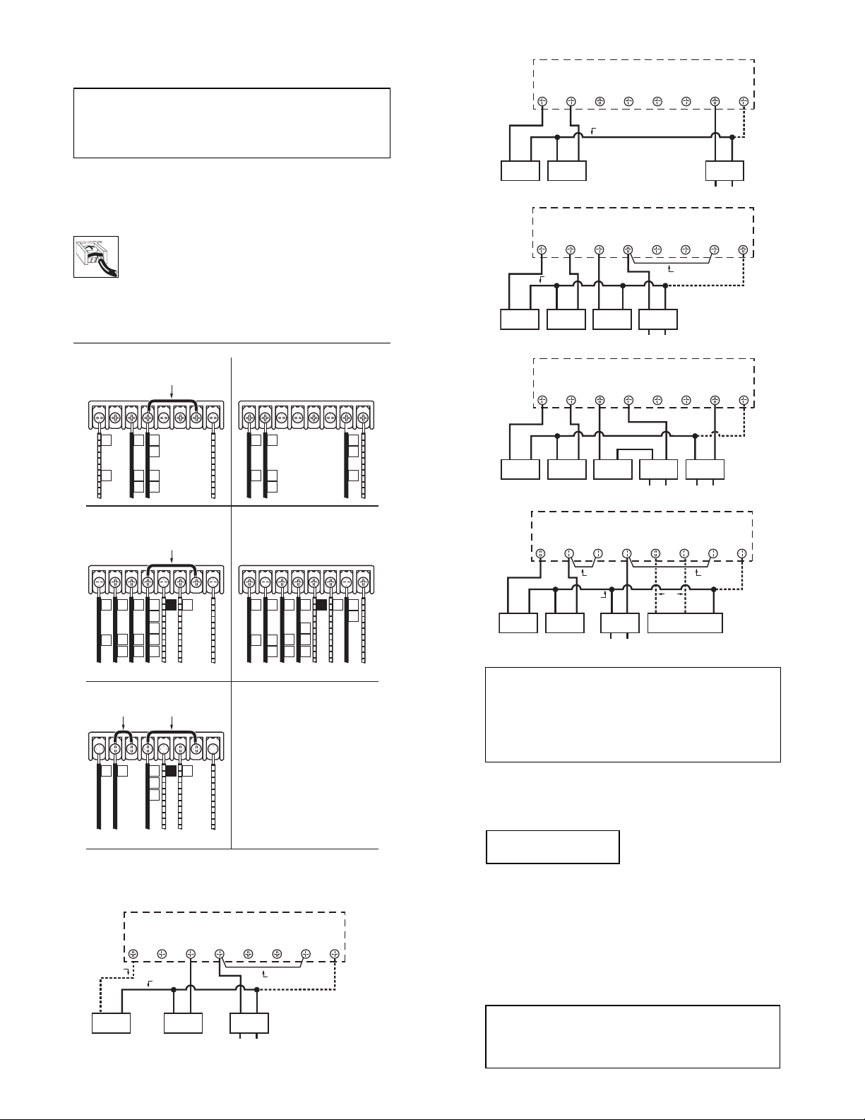
TYPICAL COOL HOOKUP
24 VAC SYSTEMS
G Y W RH B O RC C
SYSTEM
COMMON
RH-RC JUMPER REMOVED
OPTIONAL
SYSTEM
COMMON
8. Hold the base against the wall. Route the wires through the hole below the
terminal block. Position the base for best appearance (to hide any marks from an
old thermostat). Attach the base to the wall with the two screws provided.
CONNECTING THE WIRES
9. Loosen wire clamp screws just enough to slide wire under the
top black part of the clamp.
10. Using your label, and diagrams below determine appropriate
wiring for your system.
11. If you are unsure or need assistance, call the LUX Technical Assistance Dept.
(see TECHNICAL ASSISTANCE).
12. Slide proper wire between the brass back and black top clamp.
13. Tighten each screw securely.
HEATING SYSTEMS COOLING SYSTEMS
RH-RC JUMPER
GYWRHBORCC
G
F
HEATING / COOLING SYSTEMS HEATING / COOLING SYSTEMS
4- or 5-WIRE WITH ONE TRANSFORMER 5- or 6-WIRE WITH TWO TRANSFORMERS
GYWRHBORCC
G
C*
F
SINGLE STAGE HEAT PUMP WIRING
W-Y JUMPER
ADDED
GYWRHBORCC
G
PROVIDED
RH
W
R
V
H
5
4
RH-RC JUMPER
PROVIDED
RH B*
Y
W
RC
R
V
H
5
6
4
USE B OR O
NOT BOTH
RH-RC JUMPER
PROVIDED
RH B*
Y O
RC
R
USE B OR O
NOT BOTH
O
GYWRHBORCC
G
F
OPTIONAL COMMON
FOR SYSTEM POWER
GYWRHBORCC
G
F
OPTIONAL COMMON
FOR SYSTEM POWER
Dashed lines are optional.
*
Optional common wire allows
*
system to power thermostat.
*
If "Y" and "C" are both present,
then "C" is a common wire.
If a "B" wire in your system
*
is a common wire then connecting
it to the B terminal may cause
damage to your system.
Use "B" or "O" in heat pump
*
systems. Generally neither
OPTIONAL COMMON
are required in a
FOR SYSTEM POWER
conventional system.
RH-RC JUMPER
REMOVED
Y
C*
6
RH-RC JUMPER
RH B*
W
Y
R
V
H
C*
5
4
6
REMOVED
USE B OR O
NOT BOTH
O
RC
R
V
RC
R
OPTIONAL COMMON
FOR SYSTEM POWER
OPTIONAL COMMON
FOR SYSTEM POWER
These diagrams are provided for new installations
or unreferenced wires.
TYPICAL 2 OR 3 WIRE HEAT HOOKUP
24 VAC SYSTEMS
G Y W RH B O RC C
OPTIONAL
FAN LEAD
SYSTEM
COMMON
RH-RC JUMPER
PROVIDED
OPTIONAL
SYSTEM
COMMON
COMPRESSORFAN
TYPICAL 24VAC 4 WIRE HOOKUP
SINGLE STAGE HEAT AND COOL
SYSTEM
XFMR
AC LINE
G Y W RH B O RC C
SYSTEM
COMMON
COMPRESSORFAN
GAS VALVE
OR HEATER
TYPICAL 2 TRANSFORMER 24VAC 5 WIRE HOOKUP
SINGLE STAGE HEAT AND COOL
SYSTEM
XFMR
AC LINE
RH-RC JUMPER
PROVIDED
OPTIONAL
SYSTEM
COMMON
G Y W RH B O RC C
RH-RC JUMPER REMOVED
COMMON 2
COMMON 1
COMPRESSORFAN
GAS VALVE
OR HEATER
HEAT
XFMR
AC LINE AC LINE
TYPICAL SINGLE STAGE HEAT PUMP HOOKUP
COOL
XFMR
OPTIONAL
SYSTEM
COMMON
G Y W RH B O RC C
PROVIDED
OPTIONAL
SYSTEM
COMMON
USE
B or O
NOT BOTH
REVERSING
RH-RC JUMPER
VALVE
W-Y JUMPER
ADDED
SYSTEM
COMMON
COMPRESSORFAN
Dashed lines are optional.
*
Optional common wire allows system to power thermostat.
*
If "Y" and "C" are both present, then "C" is a common wire.
*
If a "B" wire in your system is a common wire then connecting
*
it to the B terminal may cause damage to your system.
Use "B" or "O" in heat pump systems. Generally neither are
*
required in a conventional system.
SYSTEM
XFMR
AC LINE
COMPLETING YOUR INSTALLATION
14. See Setup Options to configure jumpers.
15. Install two new Energizer or DURACELL "AA" size alkaline batteries at
this time. For instructions, see BATTERIES/MAINTENANCE.
NOTE
Remove sticker from display.
Do not use unnecessary force. If the body does not snap into place easily,
remove the body, re-hang it from the tabs and try again.
17. Turn the power back on to your heating and/or air conditioning system.
18. Verify that the system and its fan are operating properly. When set to a
high temperature, the heating system should provide warm air after a short
time. Likewise, a cooling system should provide cool air after a short time.
Usually sound from the furnace and air conditioning units can be heard
while they are running. The rush of moving air should be heard within a
short time after either has been started.
19. Your installation is now complete.
16. Install your PSP511A/PSP511LA
on its base. To do this hang the top of
the unit by the tabs on the base, then
snap the bottom of the unit into place.
FAN
GAS VALVE
OR HEATER
SYSTEM
XFMR
AC LINE
If you have an electric system and the blower does not operate
after installation, find the electric/gas heat jumper on the back of
the body. Move the jumper to ELEC position. No reset required.
NOTE
 Loading...