

Page 1

Welcome
Thank you for purchasing the our
LUX-N4 / LUX-N8 / LUX-N16 channel PoE NVR
This user’s manual is designed to be a reference tool for the operation of your
system.
Do not worry; you do not have to read this entire manual to be up and running. There
are quick setup instructions in Chapter 1, which will show you how to setup the
connections to the NVR correctly and how to setup a remote monitoring connection.
Here you can find information about the corresponding NVR’s features and functions,
as well as a detailed menu tree.
Before installation and operation please read the following safeguards and warnings
carefully!
BEFORE YOU BEGIN
Important Safeguards and Warnings
1.Electrical safety
• All installation and operation should conform to your local electrical safety
codes.
• We assume no liability or responsibility for any fires or electrical shock caused
by improper handling or installation.
2.Transportation security
• Heavy stress, violent vibration or water splash should be avoided during
transportation, storage and installation.
3.Installation
• Keep upright. Handle with care.
i
Page 2

• Do not apply power to the NVR before completing installation.
• Do not place objects on top of the NVR
4.Qualified engineers needed
• All examination and repair work should be done by qualified service engineers.
• We are not liable for any problems c aus ed by unauthorized modi ficat ions or
attempted repair.
5.Environment
• The NVR should be installed in a cool, dry place away from direct sunlight and
inflammable or explosi ve substances, etc.
• This product should be transported, stored and operated in an environment
ranging from 0℃ to 55 ℃.
6. Accessories
• Be sure to use all the accessories available in the product range.
• Before installation, please open the package and check all the components
are included.
• Contact your local dealer if something is broken or missing in your package.
7. Lithium battery
• Improper battery use may result in fire, explosion, or personal injury.
• When replacing the battery, please make sure you use the same model.
(CR2032 Motherboard battery).
8. Regulatory Information
• FCC information
•
FCC compliance: This equipment has been tested and found to comply with the
limits for a digital device, pursuant to part 15 of the FCC Rules. These limits are
designed to provide reasonable protection against harmful interference when the
equipment is operated in a commercial environment. This equipment generates,
uses, and can radiate radio frequency energy and, if not installed and used in
accordance with the instruction manual, may cause harmful interference to radio
communications. Operation of this equipment in a residential area is likely to cause
harmful interference in which case the user will be required to correct the
interference at his own expense.
• FCC Condition
This device complies with part 15 of the FCC Rules. Operation is subject to the
following two conditions:
1. This device may not cause harmful interference.
2. This device must accept any interference received, including interference that may
cause undesired opera t ion.
ii
Page 3

TABLE OF CONTENTS
1 FEATURES AND QUICK SETUP .................................................................... 1
1.1 Product Overview 1
1.2 Features 1
1.3 Installation 2
1.3.1 Unpacking Inspection ............................................................................................................... 2
1.3.2 Wiring Installation ..................................................................................................................... 2
1.4 Quick Connection Setup 3
1.4.1 Quick Setup Diagram ................................................................................................................ 4
1.5 Add Device 5
1.5.1 Adding Menu .......................................................................................................................... 514
1.5.2 Automatically added .................................................................................................................. 6
1.5.3 Searching added ...................................................................................................................... 14
1.5.4 Add Device Manually.................................................................................................................7
1.5.5 Modify channel configuration ................................................................................................... 14
1.5.6 Configure Front Device .......................................................................................................... 140
1.5.7 Delete Front Device ............................................................................................................... 140
1.6 Smart Phone Setup for Live View & Remote Playback 11
1.7 The Mouse 13
1.8 On-screen keyboard 13
1.9 Power On/Off 14
1.8.1 Power On ................................................................................................................................ 14
1.8.2 Power Off (Shutdown) ............................................................................................................ 15
1.10 Icons 15
1.9.1 Icons ....................................................................................................................................... 15
1.9.2 Operation Icons ...................................................................................................................... 16
2 OPERATIONS GUIDE ...................................................................................................... 17
2.1 The Right-click Menu 17
2.1.1 The Screen Switching .............................................................................................................. 17
2.1.2 P/T/Z ........................................................................................................................................ 18
2.1.2.1 PTZ configuration ................................................................................................................. 19
2.1.2.2 Quick location ....................................................................................................................... 19
2.1.3 Color setting ............................................................................................................................. 19
2.1.4 Search...................................................................................................................................... 20
iii
Page 4

2.1.5 Record ..................................................................................................................................... 21
2.1.6 The Main Menu ........................................................................................................................ 21
2.2 The Introduction of the Main Menu 22
2.2.1 The Video Inquiry (Search) ...................................................................................................... 25
2.2.2 VIDEO ...................................................................................................................................... 28
Video Settings 28
2.2.2.1 Bas ic Sett ings ...................................................................................................................... 28
2.2.2.2 Encoding Settings ................................................................................................................ 29
2.2.2.3 Snapshot .............................................................................................................................. 30
2.2.3 RECORD ............................................................................................................................. 31
2.2.3.1 Basic .................................................................................................................................... 31
2.2.3.2 Record Plan ......................................................................................................................... 32
2.2.4 NETWORK........................................................................................................................... 33
2.2.4.1 Base ..................................................................................................................................... 33
2.2.4.2 Advance ............................................................................................................................... 34
2.2.4.3 Net Apply ............................................................................................................................. 35
2.2.4.3.1 DDNS
2.2.5
PTZ ...................................................................................................................................... 31
2.2.6 ALARM ................................................................................................................................. 32
2.2.6.1 Detect................................................................................................................................... 32
2.2.6.2 Alarm Input........................................................................................................................... 34
2.2.7 SYSTEM .............................................................................................................................. 34
2.2.7.1 Base ..................................................................................................................................... 35
2.2.7.2 Display ................................................................................................................................. 36
2.2.7.3 Storage ................................................................................................................................ 37
2.2.7.4 Abnormity (Abnormality) ...................................................................................................... 40
2.2.7.5 Status ................................................................................................................................... 40
2.2.7.6 Maintain ............................................................................................................................... 40
2.2.7.7 Account ................................................................................................................................ 41
2.2.8 RS232 .................................................................................................................................. 43
2.2.9 SHUTDOWN ........................................................................................................................ 43
................................................................................................................................. 35
3 WEB AND CLIENT ...................................................................................................... 44
3.1 Web Operation 44
3.1.1 Network Connection ............................................................................................................ 44
3.1.2 The Interface of Web Operations ........................................................................................ 46
3.1.3 The Real-time Monitoring .................................................................................................... 46
3.1.4 PTZ Controls ........................................................................................................................ 48
3.1.5 Configuration ....................................................................................................................... 49
3.1.6 Search Record ..................................................................................................................... 50
3.1.7 Alarm Configuration ............................................................................................................. 50
4 TROUBLESHOOTING ................................................................................................ 52
iv
Page 5

5 MOBILE APP………………………………………………………………………….54
v
Page 6

1 FEATURES AND QUICK SETUP
1.1 Product Overview
This product is designed specifically for the use in the field of high definition long
distance analogue video surveillance and adopts H.264 video compression, hard disk
recording, TCP /IP transmission and a Linux based O S in ad dit ion t o some of the most
advanced technology in the information technology industry. These elements help to
produce a more stable, reliable and higher quality video image. The products support
synchronized video, audio recording, playback, monitoring and the synchronization of
audio and video. The products support advanced control technology and strong network
data transmission capacity.
1.2 Features
Real-time monitoring
Composite video signal interface and support TV, VGA or HDMI output simultaneously.
Compression function
Uses H.264 video compression standard and G.711 audio compression standard and
has high definition, low code rate of the video coding to decrease the amount of data to
save to HDD storage.
Recording function
Supports timing, alarm alerts, motion detection, SATA hard and local hard disks, NVR
data backup and network backup.
Video playback function
You can search videos, within the local network, by using the playback interface. As well
as this it supports multiple videos playback, fast playing, slow playing and frame-byframe playback. Video playback can be displayed the exact time of the incident using a
graphical timeline to allow you to search for event footage much more efficiently.
Camera control and alarm
Remotely installed cameras can be controlled and various alarm devices can be
connected to ensure that you know when an event has been detected. The NVR
integrates Dynamic detection, video loss, video block, multiple alarm output and scene
lighting control into its controller options.
Communication Interface
Equipped with USB 2.0 high-speed inter face and an ES AT A interface to allow for
external video backup devices. There is also an option to store data on a remote server
(cloud storage location) by connected the NVR to a local or wide area network by using
the standard Ethernet interface port (plug and play).
1
Page 7

Network functions
Supports:
• TCP / IP
• UDP
• RTP / RTSP
• DHCP
• PPPOE
• DDNS
• NTP
Also supports real-time network monitoring, video playback, control and manage men t
functions. The built-in WebViewer (WEB Server) will allow you to directly access the
NVR through a web browser.
Mode of operation
You can operate by the NVR’s front panel or using a mouse. A simple, intuitive graphical
interface is provided for intuitive operation.
1.3 Installation
1.3.1 Unpacking Inspection
When you receive the product please check that all items are present according to the
packing list on the reverse of the box.
1.3.2 Wiring Installation
Prepare for installation
Prepare your cameras, TV/display monitor, video cables, network cables, the mouse,
and power cables on a large clean fl at sur f ac e.
2
Page 8

1.4 Quick Connection Setup
NOTE: BEFORE INSTALLING ANYTHING W E STRONGLY RECOMMEND
THAT YOU CONNECT YOUR CAMERAS TO YOUR NVR AND TEST YOUR
SYSTEM FIRST.
NOTE: WE CHECK EVERYTHING TO MAKE SURE IT IS WORKING WHEN IT
LEAVES US BUT OCCASIONALLY THINGS FAIL AND IT IS BETTER TO KNOW
NOW THAN AFTER YOU HAVE FITTED EVE RYTHING!
1. Place the NVR on a flat horizontal position and connect your cameras to the
video input on the rear of the NVR.
2. Connect your TV/ display monitor to the video output on the rear of the NVR.
3. Connect the network cable to the RJ45 socket on the rear of the NVR then
connect the other end of the cable to a spare socket on the router.
4. Connect the Mouse to the USB interface found in either the front or rear panels.
5. Connect your NVR a power outlet and switch on the power.
Caution
For an external alarm device or a PTZ, please refer to the relevant instructions.
Connect the power line after all lines connected correctly.
3
Page 9
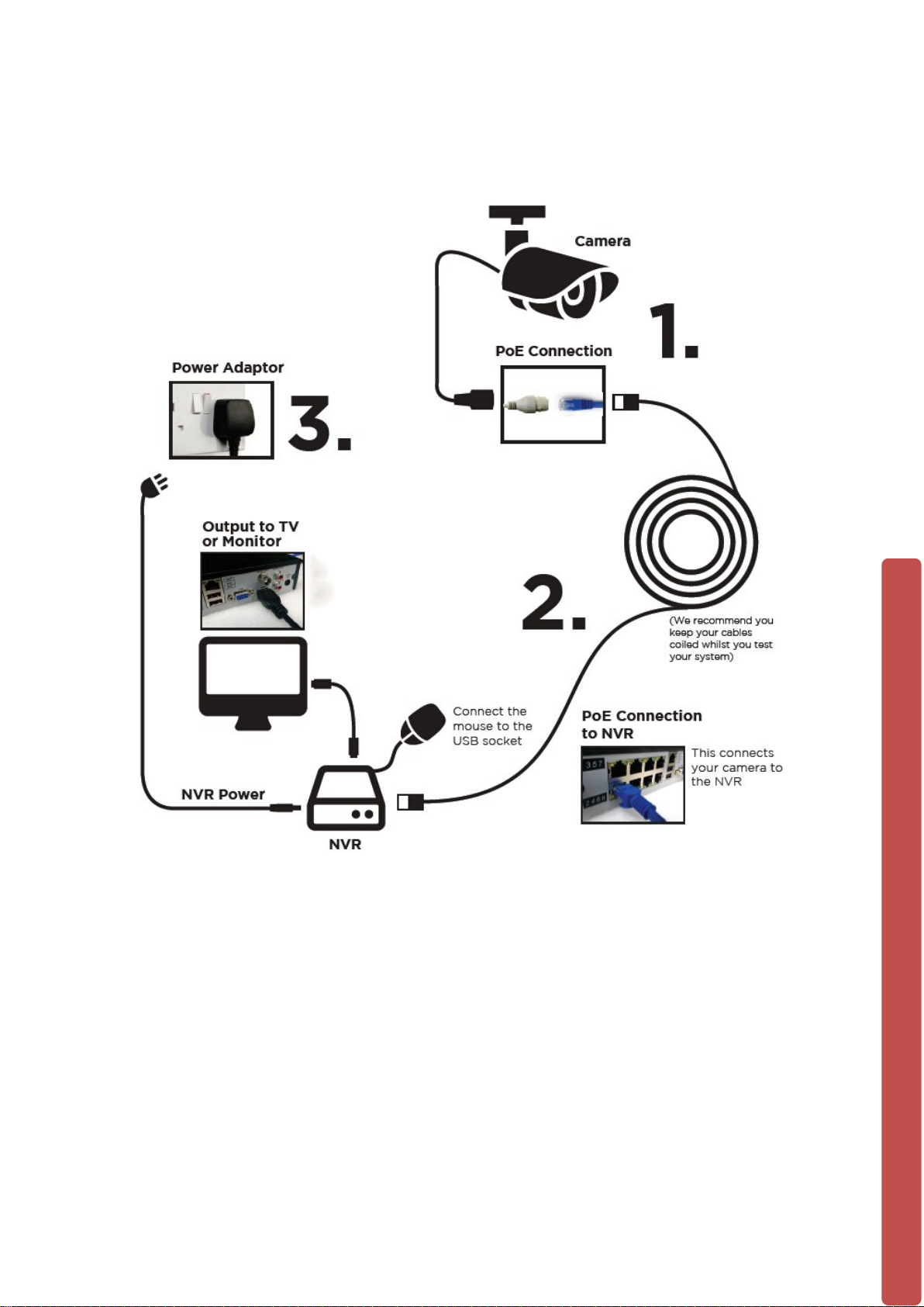
1.4.1 Quick Setup Diagram
1.5 Add Device
If the device supports IPC, should be added to IPC first. We offer three ways to add.
And support many different pr otocols.
4
Page 10

1.5.1 Adding Menu
There are three ways to login【NET channel M anag em ent】
1、Living preview, click the left mouse button + and login 【 NET channel
Management】
2、Living preview,click the button below 【NET channel Management】
3、【Main Menu】→【Configuration】→【NET channel Management】。
We provide three ways to add device, automatically, searching, manually add the
device.
1.5.2 Automatically added
No configuration, the device is automatically added.
【Main Menu】→【Configuration】→【NET channel Managem ent】→【Open
UPNP】
Note:The device should suppor t UPNP and should be in the s ame LAN.
5
Page 11
1.5.3 Searching Added
Search all the IPC can be added via internet and then choose to add. To do the
following.
Enter【NET channel Manag em ent】
Click【Filter】to choose protocol
Click【Search】
Click+ to add device or Right click【Add to】choose the channel you want or tick the
devices you want to add, then click【BatchAdd】
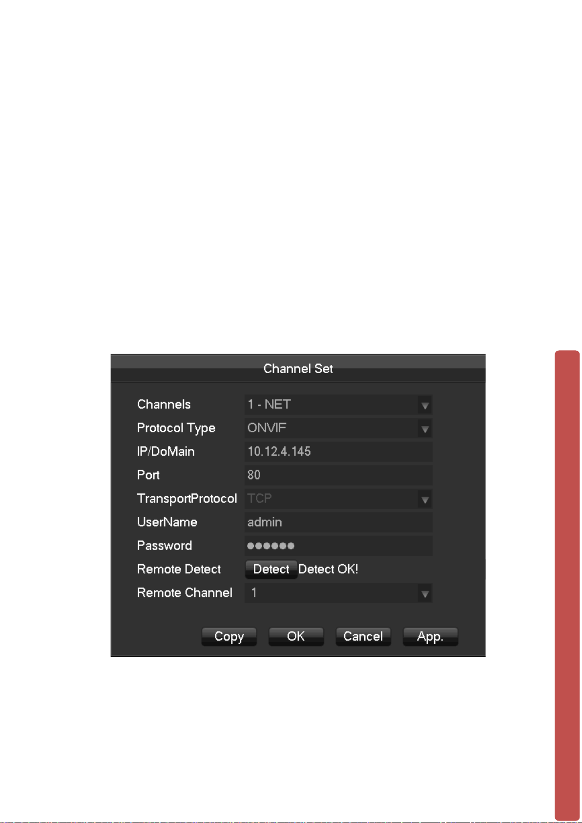
1.5.4 Add Device Manually
Enter Channel Set menu.
[Channels]Choose one channel.
[Protocol]Choose protocol supported by the device.
[IP/ Domain Name] Input front device IP address or domain name.
[Port]Input front device TCP port.
[Username] Input front device username.
[Password] Input front device password.
6
Page 12
[Remote Detect]After completing the above settings, click detect button to check
connection status.
[Remote Channel]When the front device includes multi pl e chann el s, choose one
channel for it.
Click “App” button to finish.
1.5.5 Modify channel configuration
Enter Net channel Management menu.
Click “Edit ” button of device.
Click “OK” button to finish.
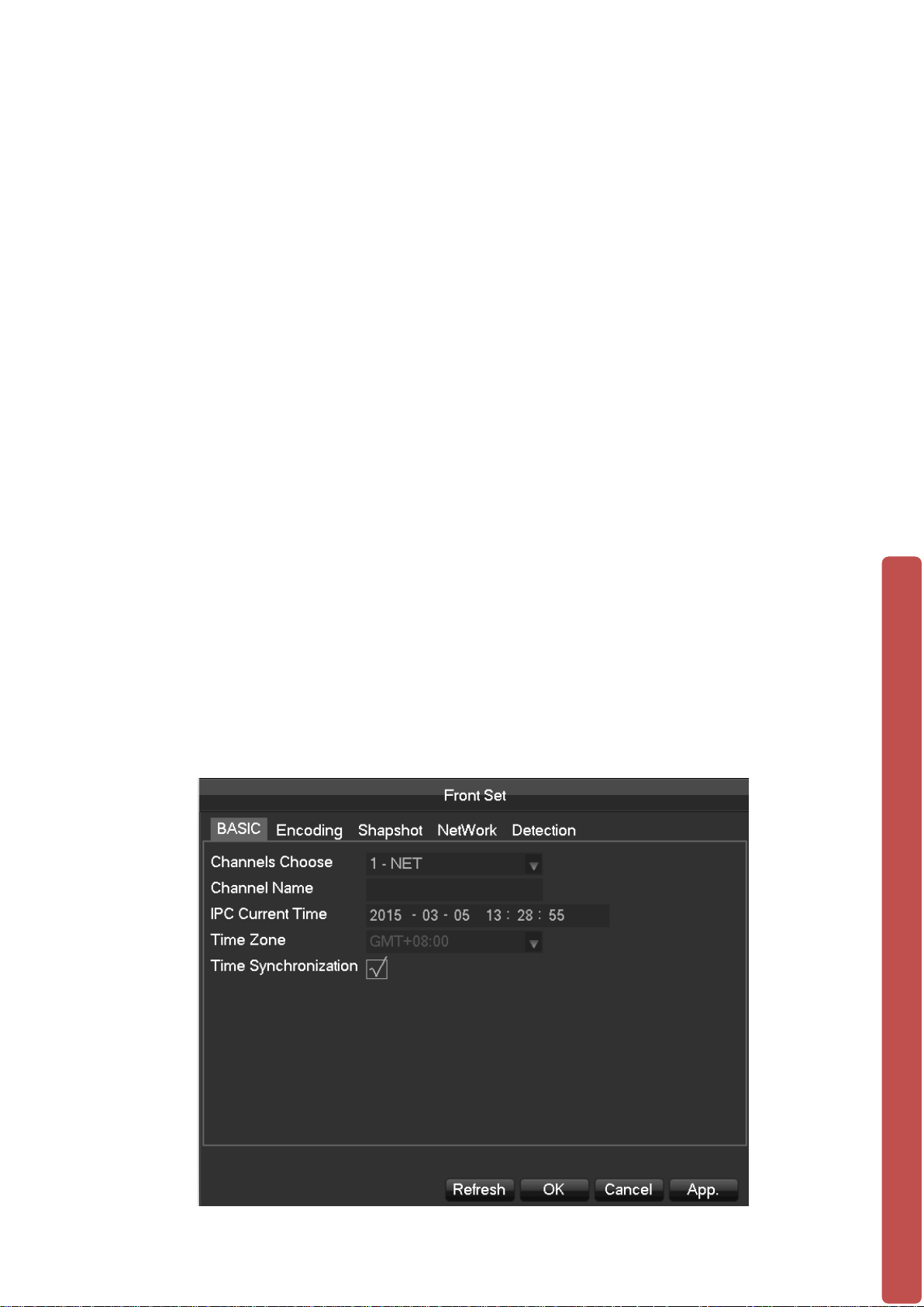
1.5.6 Configure Front Device
Basic configuration, encoding configuration, snapshot, network and motion detection of
front device can be set in NVR.
Enter Net Channel Management menu.
Click “Front Set ” button of device.
BASIC
7
Page 13
[Channel Choose]Choose a channel.
[Channel Name]Modify current channel name.
[IPC Current Time]Set IPC tine.
[Time Zone]Set time zone.
[Time Sync]Enable IPC time sync with NVR.
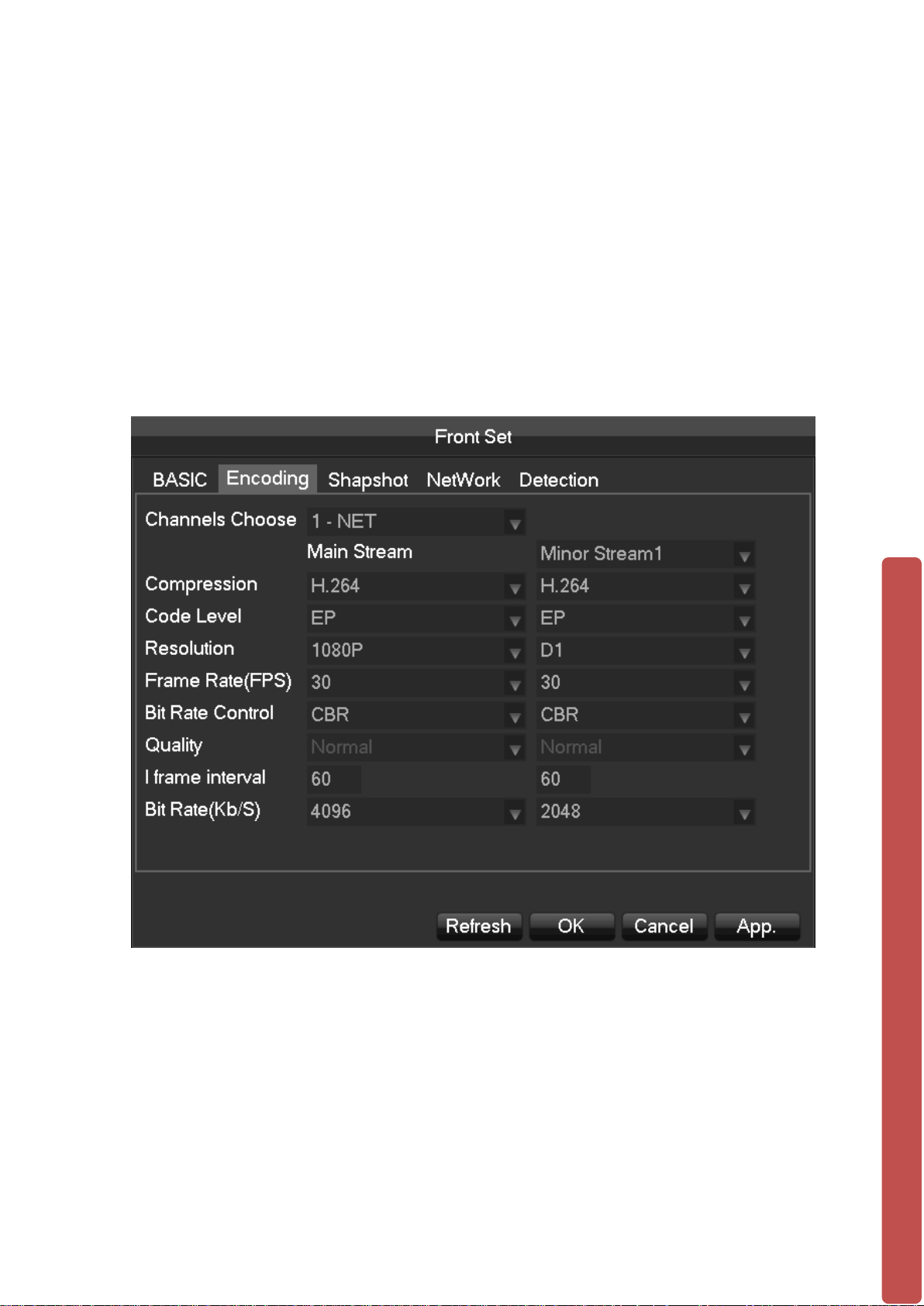
Encoding
[Channels Choose]Choose one channel.
[Code Level] H.264
[Resolution] choose main resolution and sub res ol uti on .
[Frame Rate] 1~25FPS/PAL,1~30FPS/NTSC
[Bit Rate Control]Choose CBR or VBR. When choose CBR, bit rate can be set. When
choose VBR, image quality can be set.
8
Page 14
[I frame interval]Set interval of adjacent frames. Max is 150.
[Bit Rate]Choose 1280 ,1536,1792,2048,3072,4096,5120,6144,7168,8192 or set by
yourself.
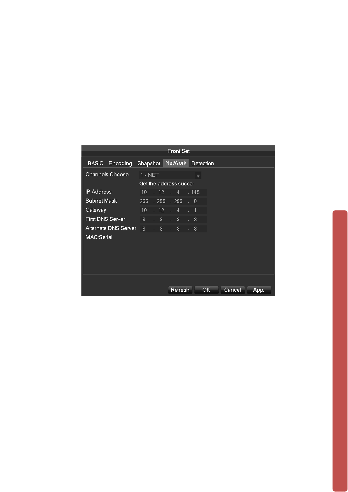
Network
[LAN1] Network connected Onvif IP Camera
[Channels Choose] Choose LAN1 (1-NET).
[IP Address] Default is set to DHCP
[Subnet Mask] Default is set to DHCP
[Gateway] Default is set to DHCP
[First DNS Server] Default is set to 8.8.8.8
[Alternate DNS Server]Set standby DNS server IP address.
[MAC/Serial] Show MAC address o f front device.
[LAN2] POE Connected Onvif IP Camera
[Channels Choose] Choose LAN2 (2-NET).
[IP Address] Default is set to 192.168.2.88
9
Page 15

[Subnet Mask] Default is set to 255.255.255.0
[Gateway] Default is set to 192.168.2.1
[First DNS Server]Set DNS server IP address.
[Alternate DNS Server]Set standby DNS server IP address.
[MAC/Serial] Show MAC address o f front device.
**** Note: IP Camera’s IP Address must set to DHCP or 192.168.2.xxx
Detection
[Channels Choose]Choose one channel.
[Enable]Enable motion detect alarm or not.
[Sensitivity]Set sensitivity level for motion detection.
[Set Area] Set area for motion detection.22*18 area can be set.
:Make sure that protocol for front device supports motion detect function.All settings are for
front device.
10
Page 16
1.5.7 Delete Front Device
Enter Net Channel Management menu.
Click delete button or right click “device delete” to delete one device. Checkmark
several device and click “Batch Delete” to finish delete.
1.6 Smart Phone Setup for Live View & Remote Playback
For the convenience of monitoring your security system on the move via your smart
phone we have provided a quick and simple remote connection setup service. Please
follow the steps below closely to successfully setup the connection for live view and
remote playback. See next page for step-by-step setup instructions.
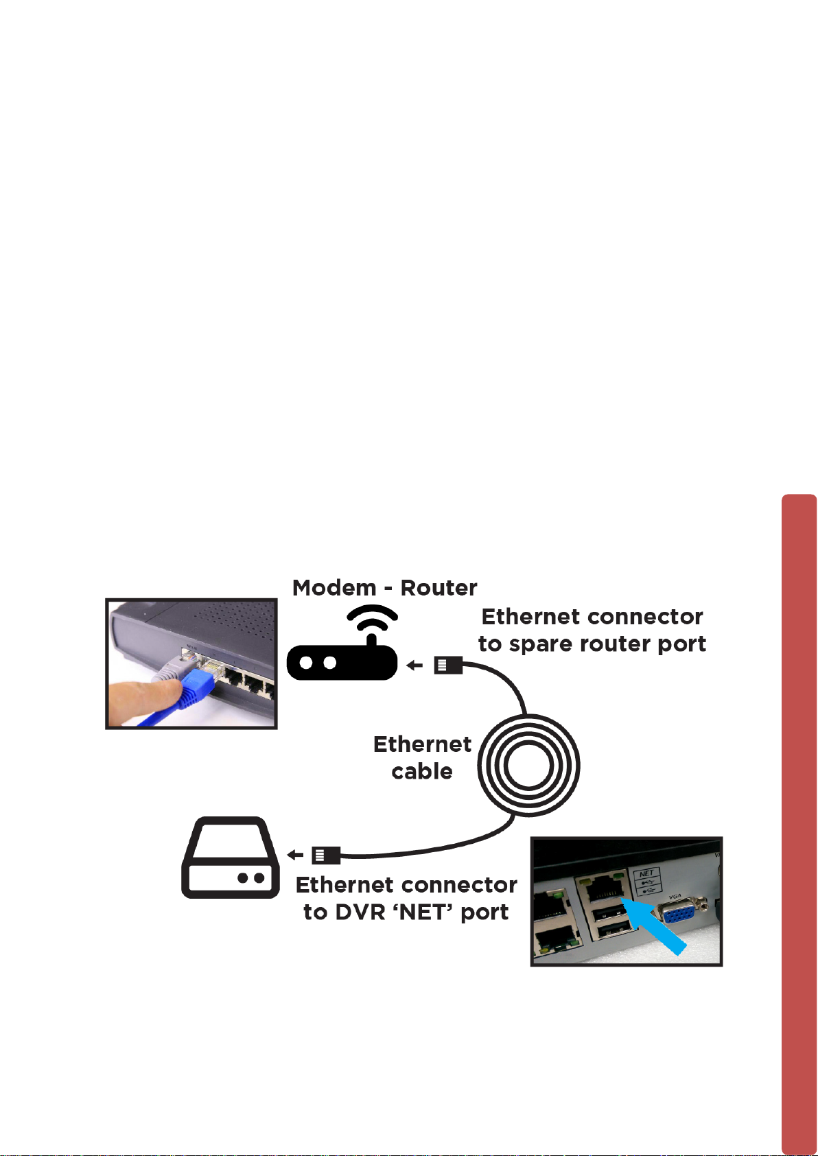
1. Internet Connection for PoE NVR (LUX-N4 / LUX-N8 / LUX-N16)
Connect the Ethernet cable into the “Net” port on the rear of the device then connect the
other end into one of the spare ports on your modem-router, as shown below.
11
Page 17
2. Download and install Mobile App
Google
Android Mobile App: D-LUX View
Apple
iOS Mobile App: D-LUX View
3. Once installed, open it up and press the button: “ + Device”
4. Input these Info.:
- Device Name
- IP Address or Domain Info.
- Port : 9000 (Default port is 9000)
- Username: admin (Default ID is admin)
- Password: 123456 (Default Password is 123456)
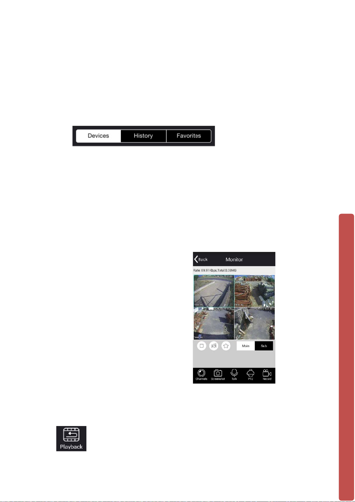
5. View Live feed Cameras
Your NVR will now be shown on the
list of camera Channels.
The video channel display screen will
then allow you to view the camera
connected to the NVR.
6. Playback
To playback and review footage select the icon shown here found on the device list screen;
12
Page 18

Choose the date, time and channel you wish to view footage from and then the app will
search for recorded footage to review.
7. Success! You should now be fully setup.
1.7 The Mouse
The mouse is used to operate all aspects NVR.
Right mouse click is used to:
• Open up a new menu in the real-ti m e monit or i ng scr een.
• Exit the current screen without saving.
Left click is used to:
• Enter the desired menu or the main screen.
• Select menu options.
• Select/unselect the checkboxes.
• When controlling a PTZ camera.
Double Click is used to:
• Play video.
• Make selected camera full screen or to exit full screen mode.
Scrolling wheel is used to:
• Control the zoom function of the PTZ cameras.
Mouse Drag can be used to select:
• Area for facial detection.
• Areas to block (for motion detection).
• Select zooming function of PTZ control.
•
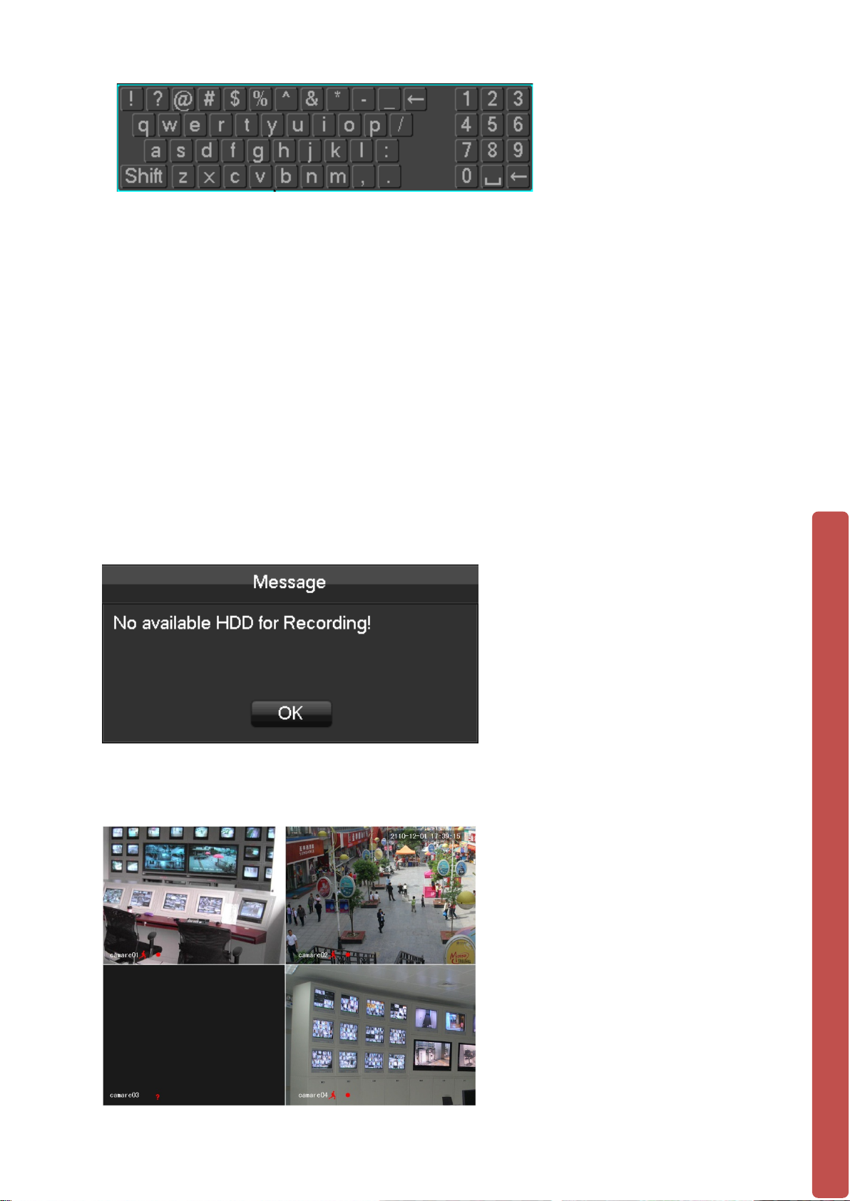
1.8 On-screen keyboard
The onscreen keyboard is operated via the mouse’s left click. To enter passwords,
usernames, values, etc.
Shift = Caps on/Caps off
Left pointing arrow = Left/delete
= Space between characters
13
Page 19
1.9 Power On/Off
1.9.1 Power On
Install the NVR correctly (as above) and then connect the power. The NVR LED should
light up light up and the NVR will boot automatically.
The NVR will then automatically detect any connected hardware (cameras, monitors,
etc.), this process should last about 30 Seconds. When this process has been
completed the NVR will enter the multi-screen real-time surveil l ance mod e.
If your hard drive is not properly connected, the following message will appear on your
screen.
Below is the multi-screen real-time surveillance mode:
14
Page 20

NOTE: Please do not use any type of power supply which is different from
the power supply included in this kit.
1.9.2 Power Off (Shutdown)
Right mouse click →【Main Menu】→【Shutdown】
NOTE: Only change or attempt to reconnect the hard disk drive after shutting
down the NVR.
1.10 Icons
1.10.1 Icons
:The channel is recording.
:The video feed of the channel has been lost.
:Motion detection functionality is on.
:The channel is currently in monitoring and locked status.
15
Page 21
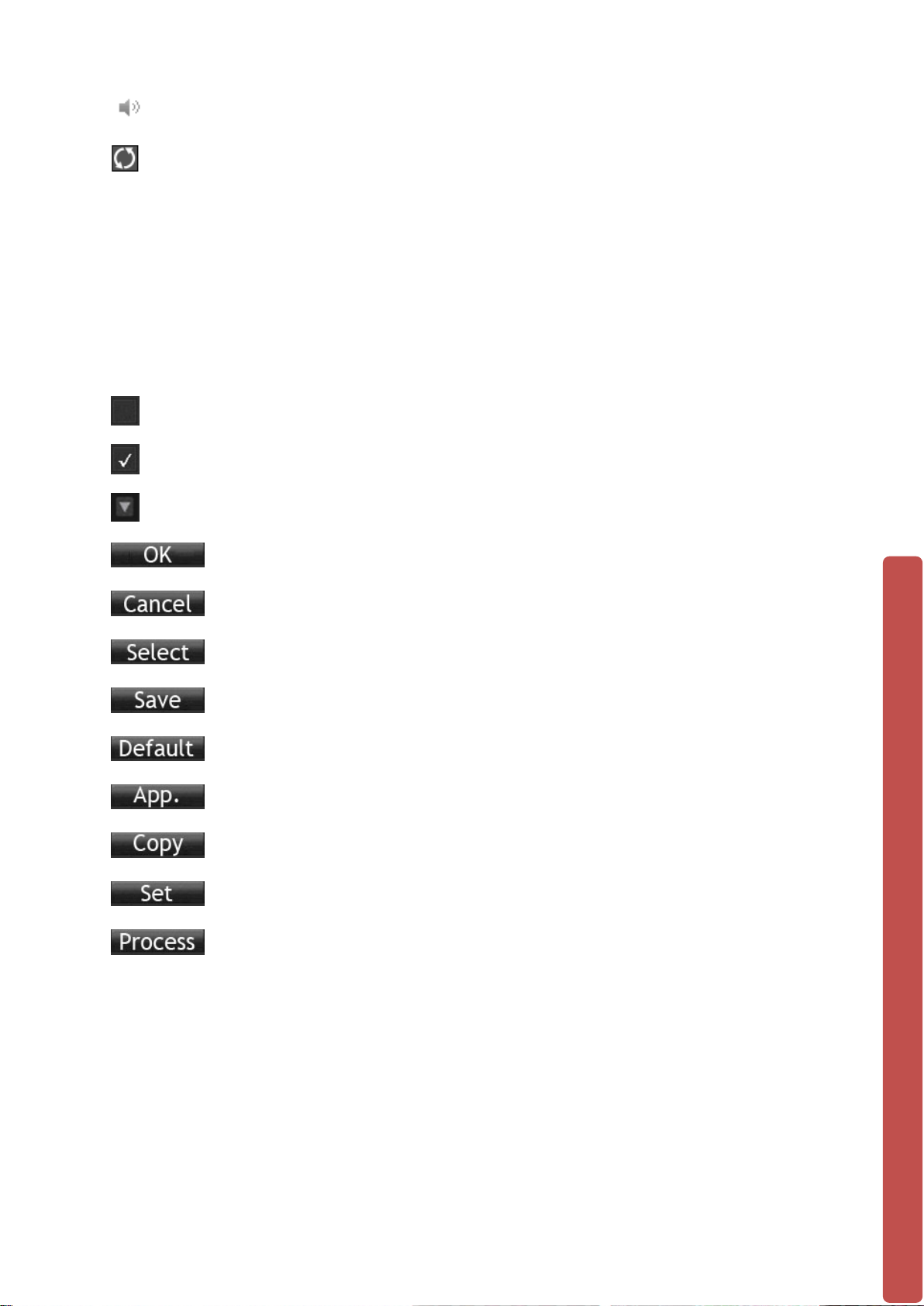
:Adjust the volume of audio output.
:Slideshow of all connected cameras, in full screen.
1.10.2 Operation Icons
: Not selecte d .
: Selected.
: The drop - down button
:Leave the interface.
:Cancel the settings.
:Set parameters.
:Save parameters
:Restore the factory settings.
:Apply current settings to the system.
:Copy current settings to other channels.
:Enter the configuration interface.
:Select and configure the processing operation triggered by
video detection or alarm.
16
Page 22

2 OPERATI ONS GUIDE
2.1 The Right-click Menu
Enter the real-time channel browsing interface. Click the right button on the mouse to
bring up the pop-up menu as shown in the figure below.
The Right button menu:
2.1.1 The Screen Switching
Click the right mouse button on the real time monitoring screen to bring up the options
list, and select either ‘View 1’, ‘View 4’ or ‘View 9’ from the list.
Users can choose to have either single, four or nine channels.
17
Page 23

2.1.2 P/T/Z
Click the right mouse button on the real time monitoring screen to bring up the options
list, and select ‘P/T/Z’ from the lis t.
When the NVR is connected with a network PTZ camera, right click the corresponding
network channel and select [PTZ] to enter into the PTZ interface. If the NVR is
connected to a simulated PTZ camera, enter [Main Menu] - [PTZ] (explained in more
detail further into the manual) to modify the PTZ protocol, the baud rate and address
bits. Then right click in the corresponding channel and select [PTZ].
The PTZ control interface is shown in the following image:
Click to enter the PTZ configuration page:
.
18
Page 24

2.1.2.1 PTZ configuration
The direction of the PTZ camera, steps, zoom, focusing, iris, preset points, cruising
between points, patrols, sweeping the boundary, calling an auxiliary switch, light switch,
horizontal rotation are controlled using the directional arrow keys.
The [Step] is mainly used to control directions. The figure can be set from 1 to 8.
Directly click or to adjust the zoom, sharpness and brightness.
PTZ supports eight directions.
2.1.2.2 Quick location
Quick location: <SIT> is in the middle of the direction arrows, shown in the red circle
below:
Make sure that the PTZ’s protocols support this function. The PTZ will turn to the
clicked point and move it to the center of screen. It also supports zooming into and out
of the video image. Drag the mouse in the quick location page to zoom into an area of
the footage. The dragged box can zoom in to the image in between 4 to 16 times. Hold
the mouse and drag it up to complete zoom of the box. Drag it down to narrow the box.
2.1.3 Color setting
If you need to set a certain color l evel configuration on the channel br owsing display
interface for a certain ti me o f day (e.g. one configuration for the daytime and another
configuration for the night time), you can set this up via the ‘Color Setting’ menu found
19
Page 25

【
【
【
【
【
on the right-click menu. You can set two time periods for two separate color
configurations that suit the lighting environment around where you view the footage
from the cameras on the display monitor.
Image color hue, brightness, contrast, saturation, gain and white-level parameters can
all be adjusted to desired levels. See screen shot of the Color Setting menu on the next
page.
Period】: Two periods can be set according to ambient light during the day and night,
device will automatically switch configuration time. Need to select the Enable box.
Hue】: Adjust the image color cast.
Brightness】: Visual image brightness (according to the environment), reduces or
increases the brightness of the image to try to make it clearer.
Contrast】: Adjusts the black and w hit e colors of the image (the greater the ratio, the
brighter the image).
Saturation】: Image color purity. The greater the value the more colorful the images
will become.
NOTE: Different mo de different function
2.1.4 Search
To playback recorded footage and search for particular video incident on a particular
date and time right click button on the real time monitoring screen to bring up the
options list Select ‘Search’ from the options and the video enquiry console will appear.
See Chapter 2.3 The Video Inquiry for further instructions.
20
Page 26

【
【
【
2.1.5 Record
To set which camera channels to have scheduled recording times or to record
continuously through the day, click the right mouse button on the real time monitoring
screen and select ‘Record’ from the options list.
You will see this window appear:
Manual】The tick boxes in this row have the highest priority and when you have
ticked the corresponding channels the NVR will record continuously.
Schedule】Record footage from the cameras at customised times during the week.
Stop】Stop recording on that channel.
2.1.6 The Main Menu
To go to the Main Menu of the NVR, click the right mouse button on the real time
monitoring screen and select ‘Main Menu’ from the options list.
Input a user name and a password.
21
Page 27

User Type
Name
Default Password
Administrator
admin
123456
User
user
123456
Hidden
Guest
111111
Default users:
NOTE: security measures of the password: If you input the wrong password three times, the
device will produce an alarm sound. After incorrectly inputting the password in five times, the
account will be locked. Please change the default password and the user name. Refer to Chapter
2.4.5 ‘Accounts’ for more details.
2.2 The Introduction of the Main Menu
The main menu is shown as the following interface:
22
Page 28

【
【
【
【
【
【
【
【
Search】Search records by types, channels, time and playback records.
Backup】backup management.
Configuration】Including Net channel, Channel, Schedule, PTZ, Alarm and RS232.
APP Center】Set up multiple extended functions, including cloud storage, P2P,
Email etc.
System】Set basic, display, storage, abnormity, status, maintain, account and
Network etc..
Shutdown】Log off the user menu, turn off the machine, restart the system, and
switch user and other operations.
The intelligent perimeter menu is shown as the following interface:
Perimeter Record】Playback based on the events time bar: including external alarm,
motion detection, intelligent and system event information .
Perimeter Setting】Rules of the perimeter and Alarm linkage configuration.
23
Page 29

No.
Configuration
Description
Channel
selection
2
Rule naming
Rule naming and set the rule line color
3
enable
Open/close the current rule
4
Capture enable
Open/close picture cap tur e fu ncti o n
5
Create/delete
Create new rule/draw new line
6
Linkage setting
Linkage setting of the current rule
Arming/disarmin
g
8
Direction setting
Detection direction setting
9
Rules list
Display all the created detection rules
2.2.1 Perimeter Intrusion detection configuration
1
7
Choose the channel need setting
Arming/disarming setting
The Configuration menu is shown as following interface:
【MAIN MENU】 left click to【CONFIGURATION】:
24
Page 30

2.2.2 The Video Inquiry (Search)
You can access the Video Inquiry either right clicking the mouse button In the real-time
monitoring screen and s elec ti ng 【search】or you can select the ‘Search’ option in the
main menu.
Video Inquiry console: this is the view before you select which time & date you would
like to view footage from.
25
Page 31

Index
Type
Description
Two options to select either videos or pictures to
when one is selected.
Allows you to select the day of the recording you
wish to view.
Choose the
channels
Allows you to select the camera channel you
wish to view the recorded footage from.
The options here can allow you to view footage
in a suspended state.
Select this option for the timeline to display at
bars), and when the motion detection sensor
Video Inquiry console: this is the view after you have selected which time & date you
would like to view footage from. You can see on the right hand side the list of video
records to look through.
Record Search interface description:
1 Record
2 Choose the time
3
4 Playback controls
5 Recoding mode
search through. A tick will appear in the box
in full-screen mode, to cycle through the
footage, stopping / playing, pausing, fast
forward, slow play, and the previous/next frame
what point on the day if/any footag e w as
recorded (displayed as green bars), when the
alarm sensor was set off (displayed as pink
26
Page 32

was set off (displayed as yellow bars).
Shows the status information of channels’ video
yellow colors to highlight timeline.
Synchronizes all footage within the timeline to
the same time.
Displays status information of the function keys,
speed, etc.
9
List
Displays the list of recorded files.
Search the records based on the footage start
time.
The channel
number
Up to 128 video records can be shown in the
M—motion detection record.
Details of the
documents
Displays the start time, end time, and the size of
the video file.
from backup menu “√”.
Key
Description
Remark
Video
Under playback mode, whilst
switch key.
Under playback mode, whilst
button or a reverse switch key.
Play/pause
►/
Backward:
6
7 Synchronization
8 Status
10 Time inquiries
11
12
13
The timeline of
the videos
The list of
records
recording within one day by using green, red,
which includes the fast-forward speed, slow
Select the channel number.
searching list. Choose file(s) and press enter or
double click mouse to view record.
File type: R—normal record, A—alarm record;
14 Backup
Playback Control:
playback:
Fast-forward
button
Video
playback :
Slow key
Tick to backup file in file list box, click the
backup button,canc el backup file ---click “√”
pressing this key, you can get a
variety of fast cycle switching speeds;
the fast-forward button can be used
as slow-release button or a reverse
pressing this key, switch through this
in a cycle. Supports a variety of slowrelease rates. The slow release
button can be used as fast-forward
Play/pause switch when in slow-play.
Backward key
Single left click = backward key.
To play in reverse;
single click again to
stop normal
27
Page 33

playback.
playback.
【
【
【
【
【
【
Manual single
frame
playback
View single frame playback by
clicking left mouse button w hen
common playback is paused.
Then click rewind or
the single-frame
playback function,
press the play
button ►/ to enter
the normal
NOTE: The player’s playback control bar shows file playback speed, channel,
time, playback progress, etc.
2.2.3 VIDEO
Video Settings
This menu contains the basic video settings, video encoding settings, the capture
channel access, and network settings.
2.2.2.1 Basic Settings
Channel】Select the desired channel.
Channel name】Select the channel name.
Channel display】Set the position of the channel title.
Time display】The position of the time title on the screen.
Time Synchronization】Time synchronization of network channels and the device.
Video cover】Set protected area of previewing and recording.
28
Page 34

【
【
【
【
【
【
2.2.2.2 Encoding Settings
You can setup each camera to a desired and specific configuration.
Channel】Select the desired channel.
Compression】H.264
Resolution】The resolution of main stream can be CIF, D1, WD1, 720p or 1080p.
Different channels correspond to different resolutions. Frame rate
setting range is also different. The channel extension stream resolution
can support D1/ CIF / QCIF.
FrameRate 】 Set the framerate of the channel on both main stream and minor
stream.
Note:Resolution and frame rate are vary depending on NVR model.
Bit Rate】Constant Bit rate or Variable Bitrates. Bit rate can be set as Constant Bit
Rate (CBR). There are 9 levels for image quality in Variable Bit Rate
(VBR), 1280, 1536, 1792, 2048, 3072, 4096, 512 0, 6144 , and 716 8 but it
has to be fixed to Constant Bit Rate when selected.
Audio】Choose channels to record sound or not.
29
Page 35

【
【
【
【
【
2.2.2.3 Snapshot
Store a image snapshot from the camera(s) when the alarm has be en tri g gered.
Channel】Select a channel.
Mode】Trigger: When this option is set the NVR with capture an image snapshot as
the alarm gets triggered.
Image Size】Select image size.
Image Quality】There are 6 levels of image quality to choose from.
Snapshot frequency】set the highest capture rate for a single camera channel,
choose between 1 frame and 8 frames captured.
30
Page 36

【
【
【
【
【
2.2.4 RECORD
This menu section will allow you to setup of record time parameters and configurations.
2.2.3.1 Basic
Video mode】Record automatically, manually or not to record.
Video expiration time】The figure is between 0 to 365.
Video package time】The figure is between 5 to 120. Default is set to 30 Min.
HDD full】Overwrite or stop recording.
Channel】Select a channel.
【Video redundancy】Open or close the redundant recording
【Prerecorded】The figure is between 0 to 30.
31
Page 37

2.2.3.2 Record Plan
【Channel】Select a channel. It uses the colors; green (Regular – Continuous, normal
recording mode), yellow (MD – Motion Detection recording mode), and red (Alarm –
Alarm trigger recoding mode).
【Copy】Copy the settings to other channels.
Click the set button to enter the following interface.
32
Page 38

【
【
【
【
【
Time 】Recording time of 6 periods can be set every day.
Regular】Check this if you want to record normally during this time set time.
Motion Detection】Check this to set Motion detection recording.
Alarm】Check this to set Alarm trigger recording.
2.2.4 NETWORK
This menu section allows you to configure the network settings of the NVR.
• It is recommended that an experienced network technician should only be
able to configure settings in this menu section.
2.2.4.1 Base
【Network Card Type】 LAN : Default IP is set to DHCP
DHCP】Enable the NVR to obtain an IP address automatically. If it is enabled, the
NVR will reboot and search for a DHCP server, and then assign a dynamic IP address.
The dynamic IP address will be displayed in the menu. Enter a static IP address if there
33
Page 39

【
【
【
【
【
【
【
【
is no DHCP service available. If you are using the advanced feature PPPOE, then the
IP/mask/gateway and DHCP are unable to be changed.
IP Address】Use()or input numbers to modify IP, then set 【subnet mask】
and 【default gateway】for this IP.
First DNS Server】Default DNS server IP address is set to 8.8.8.8 You can change
Default DNS if you need.
Alternate DNS Server】DNS alternate IP address
Physical Address】physical address of current net port
2.2.4.2 Advance
TCP】Default: 9000
HTTP】Default: 8080
UDP】Default: 9001
RTP/RTSP】Default: 1025
34
Page 40

【
Name
Configuration
DDNS type
NO-IP DDNS
2.2.4.3 Net Apply
DDNS】Dynamic DNS is a kind of system which point internet domain name to
variable IP. According to the rule of internet domain name, domain name must
associate with the fixed IP address. Dynamic DNS provide a fixed Name server for the
dynamic domain, and then guide the domain search to the IP address of dynamic user
through Name server, which can make the outside user connect to the dynamic user’s
URL. Enable the NVR to be registered to a DDNS hostname, which runs on a fixed IP
address Webclient (Webviewer).
1. Select DDNS type (NO-IP DDNS, Dyndns DDNS o r FNT DDNS)
2. Input the registered server’s IP, port, username and password.
3. Once completed, you can login in the Web client by inputting the domain name in
IE.
No-IP DDNS
Register
Register new account at www.no-ip.com
Embedded NVR/NVR Setting
Open 【Main Menu】→【APP Centre】→【DDNS】, choose NO-IP DDNS.
Refer to the following con fig ur ati on:
35
Page 41

Host IP
Refer below various Domain Name
port
8245
xxx.xxx.org(xxx:domain name created)
6. xxx.noip.us = 8.23..224.110
User name
xxx(user name registered)
password
xxxxxx(password registered)
Name
Configuration
port
80
xxx.xxx.com(xxx:domain name created)
25. xxx.doomdns.com = 204.13.248.119
1. xxx.ddns.net = 8.23.224.108
Domain name
/ IP Address
2. xxx.hopto.me = 8.23.2 24.1 10
3. xxx.dnsfor.me = 8.23.224.108
4. xxx.myvnc.com = 8.23.224.108
5. xxx.pointto.us = 8.23.224.108
Dyndns DDNS
Register
Register new account at www.dyndns.com
Embedded NVR/NVR Setting
Open 【Main Menu】→【APP Centre】→【DDNS】, choose Dyndns DDNS.
Refer to the following con fig ur ati on:
DDNS type Dyndns DDNS
Host IP Refer below various Domain Name
Domain name
/ IP Address
1. xxx.dyndns-at-home.com = 204.13.248.119
2. xxx.dyndns.org = 204.13.248.116
3. xxx.at-band-camp.net = 204.13.248.119
4. xxx.barrell-of-knowledge.info = 204.13.248.119
5. xxx.better-than.tv = 204.13.248.119
6. xxx.blogdns.net = 204.13.248.119
7. xxx.blogdns.org = 204.13.248.119
8. xxx.blogsite.org = 204.13.248.119
9. xxx.boldlygoingnowhere.org = 204.13.248.119
10. xxx.broke-it.net = 204.13.248.119
11. xxx.buys.houses.net = 184.106.100.67
12. xxx.cechire.com = 204.13.248.119
13. xxx.dnsalias.com = 204.13.248.119
14. xxx. dnsalias.net = 204.13.248.119
15. xxx. dnsalias.org = 204.13.248.119
16. xxx.dnsdojo.com = 204.13.248.119
17. xxx.dnsdojo.net = 204.13.2 48. 119
18. xxx.dnsdojo.org = 204.13.248.119
19. xxx.does-it.net = 204.13.248.119
20. xxx.doesntexist.com = 204.13.248.119
21. xxx. doesntexist.org = 204.13.248.119
22. xxx.dontexist.com = 204.13.248.119
23. xxx.dontexist.net = 204.13.248.119
24. xxx. dontexist.org = 204.13.248.119
36
Page 42

26. xxx.doomdns.org = 204.13.2 4 8.119
86. xxx.from-mn.com = 204.13.2 4 8.119
27. xxx.NVRdns.org =204.13.248.119
28. xxx.dyn-o-saur.com =204.13.248.119
29. xxx.dynalias.com =204.13.248.119
30. xxx.dydalias.net =204.13.248.119
31. xxx.dynalias.org =204.13.248.119
32. xxx.dynathome.net =204.13.248.119
33. xxx.dyndns-at-home.com =204.13.248.119
34. xxx.dyndns-blog.com =204.13.248.119
35. xxx.dyndns-free.com =204.13.248.119
36. xxx.dyndns-home.com =204.13.248.119
37. xxx.dyndns-ip.com =204.13.248.119
38. xxx.dyndns-mail.com =204.13.248.119
39. xxx.dyndns-office.com=204.13.248.119
40. xxx.dyndns-pics.com =204.13.248.119
41. xxx.dyndns-remote.com =204.13.248.119
42. xxx.dyndns-server.com =204.13.248.119
43. xxx.dyndns-web.com =204.13.248.119
44. xxx.dyndns-wiki.com =204.13.248.119
45. xxx.dyndns-work.com =204.13.248.119
46. xxx.dyndns.biz = 204.13.248.119
47. xxx.dyndns.info = 204.13.248.119
48. xxx.dyndns.org = 204.13.248.116
49. xxx.dyndns.tv = 204.13.248.119
50. xxx.dyndns.ws = 204.13.248.119
51. xxx.endofinternet.net = 204.13.248.119
52. xxx.endofinternet.org = 204.13.248.119
53. xxx.endoftheinternet.org = 204.13.248.119
54. xxx.est-a-la-maison.com = 204.13.248.119
55. xxx.est-le-patron.com = 204.13.248.119
56. xxx.est-mon-blogueur.com = 204.13.248.119
57. xxx.for-better.biz = 204.13.248.119
58. xxx.for-more.biz = 204.13.248.119
59. xxx.for-our.info = 204.13.248. 1 19
60. xxx.for-some.biz = 204.13.248.119
61. xxx.for-the.biz = 204.13.248.119
62. xxx.forgot.her.name = 204.13.248.119
63. xxx.forgot.his.name = 204.13.248.119
64. xxx.from-ak.com = 204.13.248.119
65. xxx.from-al.com = 204.13.248.119
66. xxx.from-ar.com = 204.13.248.119
67. xxx.from-az.com = 204.13.248.119
68. xxx.from-ca.com = 204.13.2 48 .119
69. xxx.from-co.com = 204.13.2 48 .119
70. xxx.from-ct.com = 204.13.248.119
71. xxx.from-dc.com = 204.13.2 48 .119
72. xxx.from-de.com = 204.13.248. 119
73. xxx.from-fl.com = 204.13.248.119
74. xxx.from-ga.com = 204.13.248. 119
75. xxx.from-hi.com = 204.13.248.119
76. xxx.from-id.com = 204.13.248.119
77. xxx.from-il.com = 204.13.248. 119
78. xxx.from-in.com = 204.13.248.119
79. xxx.from-ks.com = 204.13.248.119
80. xxx.from-ky.com = 204.13.248.119
81. xxx.from-la.net = 204.13.248.119
82. xxx.from-ma.com = 204.13.2 4 8.119
83. xxx.from-md.com = 204.13.2 4 8.119
84. xxx.from-me.org = 204.13.248.119
85. xxx.from-mi.com = 204.13.248.119
37
Page 43

87. xxx.from-mo.com = 204.13.2 4 8.119
147. xxx.is-a-caterer.com = 204.13.248.119
88. xxx.from-ms.com = 204.13.248.119
89. xxx.from-mt.com = 204.13.248.119
90. xxx.from-nc.com = 204.13.2 48 .119
91. xxx.from-nd.com = 204.13.248. 119
92. xxx.from-ne.com = 204.13.248. 119
93. xxx.from-nh.com = 204.13.248. 119
94. xxx.from-nj.com = 204.13.248.119
95. xxx.from-nm.com = 204.13.248.119
96. xxx.from-nv.com = 204.13.248.119
97. xxx.from-ny.com = 204.13.248.119
98. xxx.from-oh.com = 204.13.248. 119
99. xxx.from-ok.com = 204.13.2 48 .119
100. xxx.from-or.com = 204.13.248.119
101. xxx.from-pa.com = 204.13.248.119
102. xxx.from-pr.com = 204.13.248.119
103. xxx.from-ri.com = 204.13.248.119
104. xxx.from-sc.com = 204.13.248.119
105. xxx.from-ds.com = 204.13.248.119
106. xxx.from-tn.com = 204.13.248.119
107. xxx.from-tx.com = 204.13.248.119
108. xxx.from-ut.com = 204.13.248.119
109. xxx.from-va.com = 204.13.248.119
110. xxx.from-vt.com = 204.13.248.119
111. xxx.from-wa.com = 204.13.248.119
112. xxx.from-wi.com = 204.13.248.119
113. xxx.from-wv.com = 204.13.248.119
114. xxx.from-wy.com = 204.13.248.119
115. xxx.ftpaccess.cc = 204.13.248.119
116. xxx.fuettertdasnetz.de = 204.13.248.119
117. xxx.game-host.org = 204.13.248.119
118. xxx.game-server.cc = 204.13.248.119
119. xxx.getmyip.com = 204.13.248.119
120. xxx.gets-it.net = 204.13.248.119
121. xxx.go.dyndns.org = 204.13.248.119
122. xxx.gotdns.com = 204.13.248.119
123. xxx.gotdns.org = 204.13.248.119
124. xxx.groks-the.info = 204.13.248.119
125. xxx.groks-this.info = 204.13.248.119
126. xxx.ham-radio-op.net = 204.13.248.119
127. xxx.hobby-site.com = 204.13.248.119
128. xxx.hobby-site.org = 204.13.248.119
129. xxx.home.dyndns.org = 204.13.248.119
130. xxx.homedns.org = 204.13.248.119
131. xxx.homeftp.net = 204.13.248.119
132. xxx.homeftp.org = 204.13.248.119
133. xxx.homeip.net = 204.13.248.119
134. xxx.homelinux.net = 204.13.248.119
135. xxx.homelinux.org = 204.13.248.119
136. xxx.homeunix.net = 204.13.248.119
137. xxx.homeunix.org = 204.13.248.119
138. xxx.homeunix.com = 204.13.248.119
139. xxx.iamallama.com = 204.13.248.119
140. xxx.in-the-band.net = 204.13.248.119
141. xxx.is-a-anarchist.com = 204.13.248.119
142. xxx.is-a-blogger.com = 204.13.248.119
143. xxx.is-a-bookkeeper.com = 204.13.248.119
144. xxx.is-a-bruinsfan.org = 204.13.248.119
145. xxx.is-a-bulls-fan.com = 204.13.248.119
146. xxx.is-a-candidate.org = 204.13.248.119
38
Page 44

148. xxx.is-a-celticsfan.org = 204.13.248.119
208. xxx.is-slick.com = 204.13.248.119
149. xxx.is-a-chef.com = 204.13.248.119
150. xxx.is-a-chef.net = 204.13.248.119
151. xxx.is-a-chef.org = 204.13.248.119
152. xxx.is-a-conservative.com = 204.13.248.119
153. xxx.is-a-cpa.com = 204.13.248.119
154. xxx.is-a-cubicle-slave.com = 204.13.248.119
155. xxx.is-a-democrat.com = 204.13.248. 11 9
156. xxx.is-a-designer.com = 204.13.248.119
157. xxx.is-a-doctor.com = 204.13.248.119
158. xxx.is-a-financialadvisor.com = 204.13.248.119
159. xxx.is-a-geek.com = 204.13.248.119
160. xxx.is-a-geek.net = 204.13.248.119
161. xxx.is-a-geek.org = 204.13.248.119
162. xxx.is-a-green.com = 204.13.248.119
163. xxx.is-a-guru.com = 204.13.248.119
164. xxx.is-a-hardworker.com = 204.13.248.119
165. xxx.is-a-hunter.com = 204.13.248.119
166. xxx.is-a-knight.org = 204.13.248.119
167. xxx.is-a-landscaper.com = 204.13.248.119
168. xxx.is-a-lawyer.com = 204.13.248.1 19
169. xxx.is-a-liberal.com = 204.13.248.119
170. xxx.is-a-libertarian.com = 204.13.248.119
171. xxx.is-a-linux-user.org = 204.13.248.119
172. xxx.is-a-llama.com = 204.13.248.119
173. xxx.is-a-musician.com = 204.13.248.119
174. xxx.is-a-nascarfan.com = 204.13.248.119
175. xxx.is-a-nurse.com = 204.13.248.119
176. xxx.is-a-painter.com = 204.13.248.119
177. xxx.is-a-patsfa.org = 204.13.248.119
178. xxx.is-a-personnaltrainer.com = 204.13.248.119
179. xxx.is-a-photographer.com = 204.1 3.24 8. 11 9
180. xxx.is-a-player.com = 204.13.248.119
181. xxx.is-a-republican.com = 204.13.248.119
182. xxx.is-a-rockstar.com = 204.13.248.119
183. xxx.is-a-socialist.com = 204.13.248.119
184. xxx.is-a-soxfan.org = 204.13.248.119
185. xxx.is-a-student.com = 204.13.248.119
186. xxx.is-a-teacher.com = 204.13.248.119
187. xxx.is-a-techie.com = 204.13.248.119
188. xxx.is-a-therapist.com = 204.1 3.248. 119
189. xxx.is-an-accountant.com = 204.13.248.119
190. xxx.is-an-actor.com = 204.13.248.119
191. xxx.is-an-actress.com = 204.13.248.119
192. xxx.is-an-anarchist.com = 204.13.248.119
193. xxx.is-an-artist.com = 204.13.248.119
194. xxx.is-an-enigneer.com = 204.13.24 8.11 9
195. xxx.is-an-entertainer.com = 204.13.248.119
196. xxx.is-by.us = 204.13.248.119
197. xxx.is-certified.com = 204.13.248.119
198. xxx.is-found.org = 204.13.248 .119
199. xxx.is-gone.com = 204.13.248.119
200. xxx.is-into-anime.com = 204.13.248.119
201. xxx.is-into-cars.com = 204.13.248.119
202. xxx.is-into-cartoons.com = 204.13.248.119
203. xxx.is-into-games.com = 204.13.248.119
204. xxx.is-leet.com = 204.13.248.119
205. xxx.is-lost.org = 204.13.248.119
206. xxx.is-not-certified.com = 204.13.248.119
207. xxx.is-saved.org = 204.13.248.119
39
Page 45

209. xxx.is-uberlet.com = 204.13.248.11 9
269. xxx.webhop.org = 204.13.248.119
210. xxx.is-very-bad.org = 204.13.248.119
211. xxx.is-very-evil.org = 204.13.248.119
212. xxx.is-very-good.org = 204.13.248.119
213. xxx.is-very-nice.org = 204.13.248.119
214. xxx.is-very-sweet.org = 204.13.248.119
215. xxx.is-with-theband.com = 204.13.248.119
216. xxx.isa-geek.com = 204.13.248.119
217. xxx.isa-geek.net = 204.13.248.119
218. xxx.isa-geek.org = 204.13.248.119
219. xxx.isa-hockeynut.com = 204.13.248.119
220. xxx.issmarterthanyou.com = 204.13.248.119
221. xxx.isteingeek.de = 204.13.248.119
222. xxx.istmein.de = 204.13.248.119
223. xxx.kicks-ass.net = 204.13.248.119
224. xxx.kicks-ass.org = 204.13.248.119
225. xxx.knowsitall.info = 204.13.248.119
226. xxx.land-4-safe.us = 204.13.248.119
227. xxx.lebtimnatz.de = 204.13.248.119
228. xxx.leitungsen.de = 204.13.248.119
229. xxx.likes-pie.com = 204.13.248.119
230. xxx.likescandy.com = 204.13.248.119
231. xxx.mine.nu = 204.13.248.119
232. xxx.misconfused.org = 204.13.248.119
233. xxx.mypets.ws = 204.13.248.119
234. xxx.myphotos.cc = 204.13.248.119
235. xxx.neat-url.com = 204.13.248.119
236. xxx.office-on-the.net = 204.13.248.119
237. xxx.on-the-web.tv =204.13.248.119
238. xxx.podzone.net = 204.13.248.119
239. xxx.podsone.org = 204.13.248.119
240. xxx.readmyblog.org = 204.13.248.119
241. xxx.saves-the-whales.com = 204.13.248.119
242. xxx.scrapper-site.net = 204.13.248.119
243. xxx.scrapping.cc = 204.13.248.119
244. xxx.selpip.biz = 204.13.248.119
245. xxx.selfip.com = 204.13.248.119
246. xxx.slifip.info = 204.13.248.119
247. xxx.selfip.net = 204.13.248.119
248. xxx.selfip.org = 204.13.248.119
249. xxx.sells-for-less.com = 204.13.248.119
250. xxx.self-for-u.com = 204.13.248.119
251. xxx.sells-it.net = 204.13.248.119
252. xxx.sellsyourhome.org = 204.13.248.119
253. xxx.servebbs.com = 204.13.248.119
254. xxx.servebbs.net = 204.13.248.119
255. xxx.servebbs.org = 204.13.248.119
256. xxx.serveftp.net = 204.13.248.119
257. xxx.serveftp.org = 204.13.248.119
258. xxx.servegame.org = 204.13.248.119
259. xxx.simple-url.com = 204.13.248.119
260. xxx.space-to-rent.com = 204.13.248.119
261. xxx.stuff-4-sale.org = 204.13.248.119
262. xxx.stuff-4-sale.us = 204.13.248.119
263. xxx.teaches-yoga.com = 204.13.248.119
264. xxx.thruhere.net = 204.13.248.119
265. xxx.traeumtgerade.de = 204.13.248.119
266. xxx.webhop.biz = 204.13.248.119
267. xxx.webhop.info = 204.13.248.119
268. xxx.webhop.net = 204.13.248.119
40
Page 46

270. xxx.worse-than.tv = 204.13.248.119
271. xxx.writesthisblog.com = 204.13.248.119
User name
xxx(user name registered)
password
xxxxxx(password registered)
FNT DDNS
FNT DDNS is built-in professional dynamic DNS service. You can register directly in the
device .Specific steps are as following.
【Main menu】-【Network】-【Application】-【DDNS】,choose FNT DDNS
1:Select FNT DDNS and Enabled it.
2:Input one user name, there will be a domain name generated auto.
Domain name = user name.faceaip.net.
3:Input the password
4:Click “Register” button. If the domain name is not registered, it will pop up a
message that connect DDNS server successfully otherwise it will prompt that the
registration is failed . Suggestion: you’d best change the DNS server in basic
configuration to the router's DNS server
5:Click the “ok” button to complete the settings.
41
Page 47

【
【
【
2.2.5 Email
Email】Enable the function to set the SMTP server’s port, username, password, the
sender’s mailbox and receiver’s mailbox.
For Example: Google's SMTP server requires authentication, so here's how to set it up:
SMTP server: smtp.gmail.com
Note: In order to store a copy of outgoing emails in your
Gmail or Google Apps Sent folder, log into your Gmail or
Google Apps email Settings and:
Click on the Forwarding/IMAP tab and scroll down to
SMTP port: 465 (SSL)
the IMAP Access section: IMAP must be enabled in order
SMTP
username: (e.g. xxx@gmail.com or
for emails to be properly copied to your sent folder.
example@yourdomain.com)
SMTP password: Your Gmail or
Google Apps email password
SSL required: yes
FTP】Choose to upload records or images.
1. Set FTP server’s IP address and port (Default: 21).
2. Create an account in FileZilla Server on a desktop computer.
3. Fill in the username, password and remote directory when the account
has been created.
4. Set the file length, channel, and time for recording, type and date.
5. Tick alarm, motion, general record or images to upload.
NTP】Turn the NTP On/Off. The network time protocol allows the NVR to sync with
NTP server time automatically.
Server IP: Input IP of NTP server. Default is set to time.nist.gov
Port:The Default port is 123.
Update cycle: The interval time is between 1 to 65535 min.
Default is set to 1440 min.
42
Page 48

【
【
【
【
【
【
【
【
【
【
IP Filter】NVR authority management. If you enable the white list, only the filled IPs
can be connected. This system supports a maximum of 64 IPs.
IP Filter】NVR authority management. If you enable the white list, only the filled IPs
can be connected. This system supports a maximum of 64 IPs.
Network Transfer a bil ity】Transfer modes and the number of network connections,
downloads.
Alarm server】reserved interface.
2.2.5 PTZ
This menu section allows you to set up an IP PTZ camera and its connection to your
NVR. Only compatible PTZ cameras will be able to be setup with the NVR.
【Channel】Select the channel.
Protocol】Select a associated protocol (e.g. PELCOD)
Address】Set address. Default : 1.
Note: this address has to correspond with PTZ address, or the PTZ will not
be controlled.
Baud Rate】Select the baud rate. Default is 9600.
Data Bits】default: 8
Stop Bits】default: 1
Parity】default: None
31
Page 49

2.2.6 ALARM
2.2.6.1 Detect
Enter [main menu]-[detect].
[Channel] Select the channel.
[Alarm type] Dynamic monitoring, video loss and vi deo bl ind c an be selec te d.
:Open the enable switch.
[Sensitivity] Set sensitivity of the network channels.
[Set area] It should be set in the IP CAMERA.
[Process] Click the button to set the alarming time, linkage and the handling method.
32
Page 50

[Linkage Set] When an alarm is triggered, the system will activate a linked set of
actions including PTZ recording, touring activation and footage recording.
If you select [Show Message] in linkage settings, the following message will pop up
when the alarm occurs.
33
Page 51

【
【
【
【
2.2.6.2 Alarm Input
Enter [main menu]-[alarm]-[alarm input].
Alarm input channel no.】Select a channel.
Enable】Select the enable switch.
Type】It can be normal open or close.
Process】and 【Linkage】Refer to [Detect].
2.2.7 SYSTEM
This menu section allows you to set the general and basic NVR settings.
The menu section contains 10 sub menu sections:
1. Basic
2. Display
3. Storage
4. Abnormity
5. Status
6. Maintain
7. Account
8. RS232
34
Page 52

【
【
【
【
【
【
【
【
【
【
2.2.7.1 Base
This menu section sets up the basic settings for the NVR.
System Time】Set the current time
Daylight Saving Time (DST) 】Click “DST” to enable the function, and enter the
local DST starting and ending time. Default: Enabled
Date Format】Modify the date display format Default: MM DD YYYY
Date Separator】Select the separator for dat e Default: /
Time Format】24hr or 12hr display mode Default: 24
Language】Select language.
NVR No.】Number more than one NVR.
Video Standard】Default: NTSC.
Auto Logout】This ranges from 0-60 minutes. 0 means no setting. NVR will
automatically let user quit after standby time’s vacancy.
Channel mode】The selection of local channels and network channel s .
35
Page 53

【
【
2.2.7.2 Display
This menu section allows you to adjust the display settings of the NVR so you can set the
desired configuration you want
• GUI
Menu Transparency】Adjust transparency.
VGA Output】Select VGA resolution. T he default is 1024×768@60Hz.
• Output mode
Adjust the sliders for each setting to change the display output on the connected display
monitor.
36
Page 54

【
【
• Tour configuration
Setting tour mode and interval between rotation , the time is within 5-120s,the mode
include single screen, four-, eight-, nine-, sixteen-screen.
Motion Tour Type】Set the motion detection tour mode
Alarm Tour Type】Set the alarm tour mode
Note: Shortcut Setting: click the button at the top right corner of the
monitoring picture or press the Shift Key to switch, you can control the tour.
2.2.7.3 Storage
• HDD Management
37
Page 55

【
【
Format】It is possible to format an individual HDD.
Note: Hard disk format operation result in the loss of video data
Set】Set HDD as read-write, read only or redundancy mode. In read only mode,
video data cannot be covered.
• HDD Re cord
• Backup
Connect an External USB device with the USB port to backup in the “Record Backup”
menu.
38
Page 56

【
【
【
【
【
【
Detect】Identify external USB device and display the device information.
Backup】Tick the external device and click【Backup】to enter the backup
menu .Select the record start-stop time and click
Add】Add files in list.
Tick the record you want and click【Start】to backup and display time remaining.
Delete】delete all data in USB backup device
Note: this operation probably cause permanent data loss
• Cloud (SendNetDisk)
Set cloud disk uploading of alarm message.
Bind】click it and use the verification code which you get to bind in the
corresponding website.
Select】choose the channel which apply this function.
39
Page 57

【
【
【
【
【
【
【
【
2.2.7.4 Abnormity (Abnormality)
Disk low Space】Alarm when hard disk capacity is lower than setting.
No Disk】Alarm when HDD is not present or cannot be detected.
Network Failure】Alarm when network is not connected.
Process Mode】includes【Alarm Output】, 【Display On Screen】 and 【Send
Email】,【pushed to phone】and recording linkage.
IP Conflict】Alarm when IP address conflict.
Process Mode】 is same as 【No Disk】’s 【Process Mode】
Disk Error】Alarm when there is error in reading and writing hard disk.
Process】includes:【Alarm Output】, 【show message】,【Send Email】 ,
【linkage record】,【snapshot】and 【buzzer】.
2.2.7.5 Status
You can see the BSP and on-line users.
2.2.7.6 Maintain
You can see logs of the system, product information, default settings and maintain
information in the following interfaces.
40
Page 58

Default: Auto-Reboot System is set to Every Sunday at 2:00 am
2.2.7.7 Account
Note: Group and user names can be from 1-6 characters in length. Valid
characters include letter, numbers, and limited symbols: underline, subtraction sign, dot,
you may not use a space as a leading or ending character.
41
Page 59

【
【
【
3 guest user Def ault User
There is no limit to the number of groups or users. By default there are two different
group levels: admin and user.
User management determined upon two levels: the group and the user level.
+
Group and user names cannot be dupli cated, and each user can only belong to one
group.
3 User Group Status
1 admin admin Login Net
2 user user Normal
Add users】add group member information and set authorities.
Default users are: “admin”, “user”, the pas sword of first two username is
123456. “admin” has advanced authorities; “user” only has surveillance
and playback authority .
“guest” Default: password is 11111, cannot delete. Viewing only.
Enter【Add users】input username, password and select group and
reusable options. Reusable allows the account to be used by multiple
logins.
A user can only belong to one group. User rights cannot exceed group
rights.
Modify users】modify existing group member information and authority.
Add group】add group and set group authorities
Set a group and authorize 60 items including control panel, shut down,
live view、playback, record, record backup, PTZ control, account,
system information, alarm in /out setting, system configuration, search
log, log delete, upgrade, operation authority, etc.
42
Page 60

【
【
【
【
【
【
Modify group】modify existing group information.
Modify Password】change password
1. Select a username input the old password and new
password twice.
2. Click【Save】to confirm
3. Password can be in 1-6 numbers, letters or symbol; blank in
beginning and end is invalid.
4. The account with management authority could change
others’ password.
2.2.8 RS232
Function】Select the appropriate the serial
Baud Rate】Set baud rate.
Data Bit】Default: 8
Stop Bit】Default: 1
Note: Some models are without an RS-232 port, please see Speci fi cat ions .
2.2.9 SHUTDOWN
Please see Chapter 1.8.2 Power Off (Shutdown)
43
Page 61

3 WEB A ND CLIENT
3.1 Web Operation
This section will provide you with instructions on how to remotely access your NVR’s
live feed and recorded footage via a web browser on a computer work station.
3.1.1 Network Connection
STEP 1: Right Click on the realtime multi-screen and select ‘Main Menu’.
STEP 2: Select/Click on ‘NETWORK’.
44
Page 62

STEP 3:
You now need to access your router’s setup interface to input the
(input fields are usually named ‘
’ and found in the advanced settings of the
TCP
interface). Please refer to your router’s manual for details on how to ‘
Port Forward
port number
8080
’.
STEP 4:
In the address bar on your Internet Explorer Browser window, type in the IP addr es s
assigned to the NVR (This is the IP address you’ve taken note of in
Step 2
).
Install ActiveX: Right click and choose install. If installation is blocked by Windows,
please add the IP as a trusted site or lower your Internet Explorer security settings to
allow this.
Install Control
The following interface will popup when you input your username, password and click
“Login”. Click “Exit” to quit.
Login screen
45
Page 63

Index
Name
Description
1
Channel
Channel selection
Local playback: playback local record
window
Surveillance
window
Image color: modify brightness,
download path and reboot
5
PTZ control
PTZ control menu
System configuration, record search,
alarm setting, exit, etc.
3.1.2 The Interface of Web Operations
If you have successfully completed the previous steps and logged in successfully you
will see the WebViewer user interface (GUI) below:
WEB Interface
Description:
2 Function key
3
4
Image color &
other saturation
Open all: play live views in surveillance
Change window layout
contrast and
Other: set capture path, record
6 Menu
3.1.3 The Real-time Monitorin g
Whilst in the WEB interface, sel ect t he foc us window within the live window . The focus
window has a light blue border.
From the left channel column select channel, as shown in the following interface .
46
Page 64

Channel Choices
Click on 2 areas in upper right corner and you can choose to open / close the channel
of the main stream or secondary stream. Above the live video window the current
NVR's IP and rate information is shown (please see image below).
Stream information
Lower left corner shows the current video channel name.
Upper right corner shows the current video time information.
Click “ ”(Lower left corner of the display window)to switch between
single screen and multi-screen.
Lower right corner of the display window will display the function keys, as the following
interface (next page).
47
Page 65

Function Key
Area zoom: Video images can be enlarged.
Multi-screen switch: switch from single screen to multi-screen and vice versa.
Local record: save and record video to a local HDD while in a live view. Set
recording path in configuration.
Capture: capture of the present channel, set the path in “other”.
Sound: on/off sound.
Off video: off the focus w i ndow video.
3.1.4 PTZ Control s
Set protocol (see【Setting】→【PTZ】)
Control PTZ direction, step size, zoom, IRIS, preset, tour, pattern, border scan, light,
wiper, auto pan, etc.
Step size controls PTZ direction and speed, e.g. step size 8 moves faster than step size
1.
Eight directional rotations: up, down, right, left, up-left, up-right, lower left, lower right.
PTZ control
48
Page 66

Border scan
Operation: select the camera line and scan of the left/right margin by using the
directional button. Click the Settings button in the left /right margin position to determine
the left border scan by the camera.
Preset
Operation: to modify the preset positions by using the directional button and inputting a
preset number, then click “Add” to save.
Tour
Operation: select “Tour”; it is the point between the first cruise line and the cruise input
box value. Add input numbers in “Path” and “preset”. Click【Add Preset】to add one
preset into the cruise path, and repeat to add additional presets. Click 【Clear Preset】
to delete a preset, repeat to delete more.
Pattern
Operation: Click “Pattern” in order to record an automated pattern. Then, go back to the
PTZ controls in order to modify the zoom, focus and IRIS, etc. Stop recording in
“Pattern” setting to save the pattern.
AUX
On/off one of AUX channels.
Wiper
On/off wiper under protocol.
3.1.5 Configuration
Access NVR’s local configuration menu by clicking the ‘System Setting’ option.
Configuration
49
Page 67

3.1.6 Search Record
Click the ‘Search record’ option to open the search interface, you can search and
operate record, alarm, motion, local record.
Search record
By selecting the record type, start & end times, and clicking the check button, you will
get a list of files recorded on to the NVR. Select the appropriate file and download it so
it can be played.
Play
Double click a search result to play in video window. Control the playing video by the
control keys at the bottom of the user interface window. At this point, the bottom of the
video window will display the video control buttons, where video playback can be
controlled.
Download: select a searched video to download to local. The download speed and
percentage are displayed on the bottom of the screen.
Searching
3.1.7 Alarm Configuration
Click the 【Alarm】 to enter the alarm setup menu, users can set up and operate the
alarm mode.
50
Page 68

Alarm configuration
Choose a type of alarm on the menu. These options include; monitor video loss, motion
detection, disk full, disk error, video mask and external alarm.
Click 【Video Pop-up】, this opens the video loss, motion detection, hard disk full, hard
disk failure, video block and video encoder alarm pop-up linkage.
Click 【prompt】opens the prompt: When an alarm occurs in real-time monitoring it will
make a popup alarm window appear in the menu.
Click 【Sound Pop-up】, you can choose a pre-recorded alarm tone on the local hard
drive when an alarm occurs, tone file in WAV format.
51
Page 69

4 TROUBLESHOOTING
NVR startup failure or continuously reboots
Possible reasons:
1. The system has been damaged fro m a bad NVR update.
2. There is a problem with the NVR main board, please contact supplier.
3. There is a HDD error. Replace faulty HDD.
Remote control does not work
1. Check for batteries in the remote control.
2. Check batteries’ power level.
3. Check if remote receiver is obscured.
4. Check if the NVR’s address corresponds to the remote control address.
NVR cannot control the PTZ camera
Possible reasons:
1. RS-485 cable connection error, A, B ports are inversely connected;
2. PTZ decoder, protocol, baud rate, address are incorrect;
3. Parallel connect a 120Ω resistor to resolve signal reflex caused by too many
PTZs on the line.
4. The RS-485 ports in the NVR are defective.
Blurred screen in preview mode
Possible reasons:
Please make sure your cameras matches your video format selected in the General
menu.
E.g. camera is NTSC standard but the NVR is PAL standard, the preview would be
blurred.
Blurred screen in playback mode or failure to playback records
Possible reasons:
1. Procedure error, reboot the NVR
2. HDD error, test or change out the HDD
3. NVR hardware failure, contact your local supplier
52
Page 70

When you can’t connect NVR through network
1. Check the physical network connection is correct.
2. Check the NVR network configuration parameters.
3. Check whether IP conflicts exist in network.
Download recording cannot be played
Possible reasons:
1. Player installation er r or.
2. The USB or HDD device has an error.
3. Do not install graphic software later than DX8.1.
Internet Explore Crash (Version 8 or before)
Close IE explore, enter into the tool bar:
DO NOT CHECK
Internet Expl orer tool bar
53
Page 71

Chrome Plug-in (NPAPI)
NPAPI is the last century by the Netscape (Netscape) developed a browser plug-in
application programming interface, which allows the browser to call external
applications.
Since NPAPI architecture too old, there are security issues, it is difficult to maintain,
the user experience is not good for various reasons, coupled now with HTML5 the
alternatives, and does not support moving platforms and other reasons, NPAPI plug-in
has begun to withdraw from the stage of history.
Now, Chrome just shield (from 42 starts), not to the extent that is not supported, you
can also manually open it.
Google chrome version: 42 version fr om the begi nni ng , Google shield the NPAPI.
Problems performance: It won’t prompt to download ActiveX.
How to open it
chrome://flags/#enable-npapi, find NPAPI Mac,Windows, enable it.
54
Page 72

55
Page 73

MOBILE APP
To be able to remotely access your NVR from your mobile smart device please download one of
our Apps from either the Google Play or Apple App store.
Scan the QR codes below with you mobile smart device to be directed straight to the app
download source:
ANDROID APP
DOWNLOAD
iOS APP
DOWNLOAD
For more information about our NVRs and a vailable
cameras & accessories, please visit our website:
http://www.luxcctv.com
Download our mobile apps to remotely operate your NVR on
the move.
56
 Loading...