

LUPUSNIGHT®
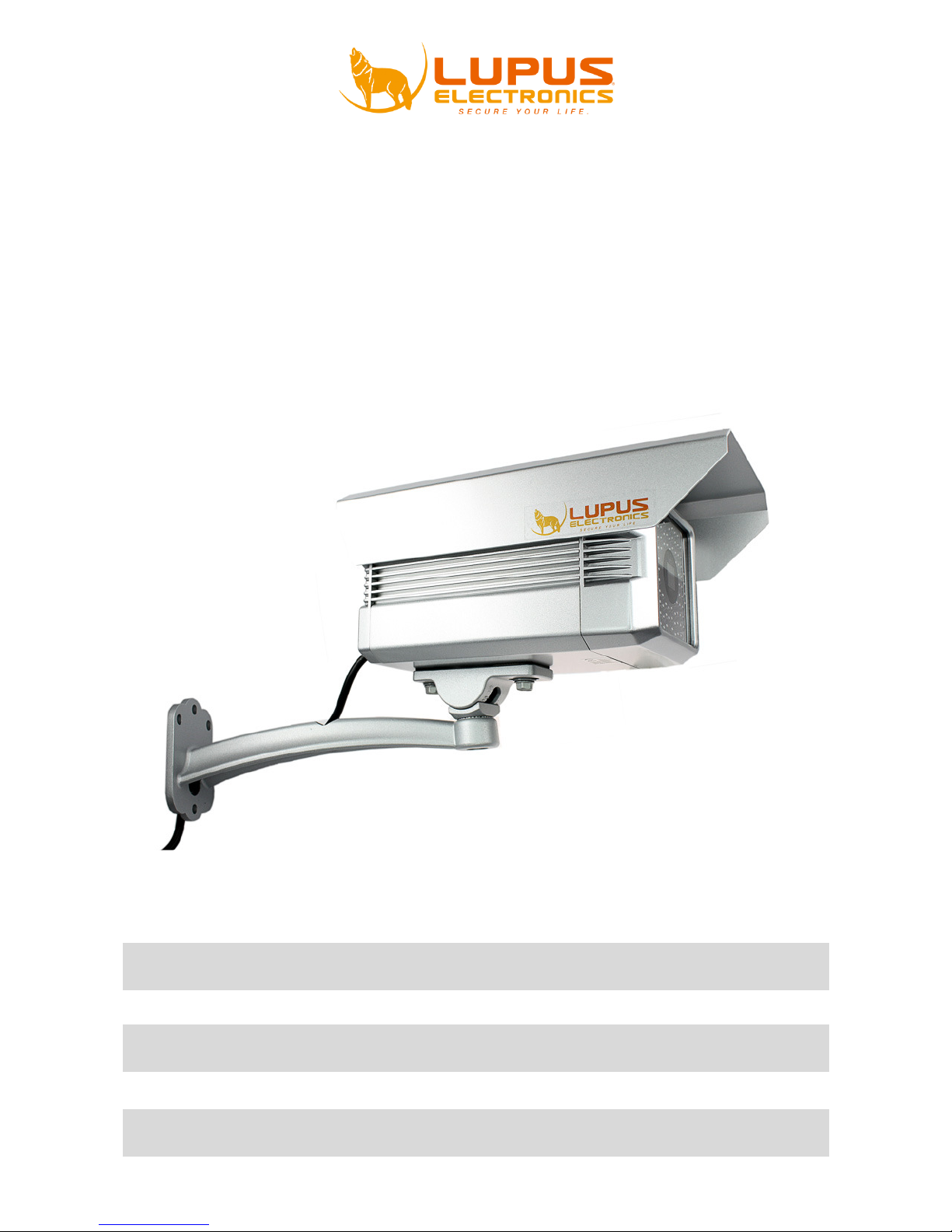
LE-308
Benutzerhandbuch
Manuel de l’Utilisateur
User Manual

Vielen Dank für den Kauf der LUPUSNIGHT® Kamera. Bevor Sie die Kamera in Betrieb
nehmen, lesen Sie sich die folgenden Sicherheits- und Installationshinweise sorgfältig
durch.
Bewaren Sie das Handbuch sorgfältig auf um im Nachhinein offene Fragen klären zu
können. Die Beschreibungen, Bilder und Technischen Daten können sich im Sinne des
technischen Fortschritts ändern.
Diese Kamera ist für den Innen- und Außeneinsatz geeignet.
WICHTIGER HINWEIS
Das oben zu sehende Sicherheitshinweis ist auf der Kamera
angebracht.
Besonders bei diesem LUPUSNIGHT Modell müssen Sie auf die
Sicherheitshinweise achten, da es direkt an eine 220/240V Leitung
angeklemmt wird. Falls Sie sich mit der Installation einer Solchen nicht
auskennen, kontaktieren Sie einen Elektronikfachmann.
Das Blitzsymbol in einem Dreieck, weist auf die Gefahr eines elektrischen Schlags
hin. Durch die hohe Betriebsspannung des Gerätes könnten Personen zu Schaden
kommen.
Das Ausrufezeichen in einem Dreieck weist auf für die Installation und den
einwandfreien Betrieb der Kamera wichtige Hinweise hin. Lesen Sie diese sorgfältig.
WARNUNG:
UM DIE GEFAHR EINES STROMSCHLAGES ZU VERRINGERN, FÜHREN SIE DIE
INSTALLATION NIEMALS IM FREIEN BEI NÄSSE DURCH.
INSTALLATION:
"DIE INSTALLATION DER KAMERA SOLLTE NUR VON QUALIFIZIERTEN
FACHKRÄFTEN VORGENOMMEN WERDEN."
Hinweise zur Benutzung und Installation
•
Richten Sie die Kamera nicht direkt in die Sonne
•
Richten Sie die Kamera nie direkt in ein Spotlicht
•
Behandeln Sie die Kamera behutsam, starke Vibrationen oder Stöße können die
Kamera beschödigen.
•
Berühren Sie niemals Interne
•
Installieren Sie die Kamera nich
Dies könnte die Bildqualität beeinträchtigen.
•
Installieren Sie die Kamera nicht direkt auf einen Aluminium oder Eisenmast ohne
den Fuß der Kamera mit einer Gummierung von dem Mast zu isolieren. Das
Kamerabi
ld könnte gestört werden.
•
Beachten Sie die max. Feuchtigkeits
*Sollten Sie Fehler feststellen
Falls Fehler auftreten sollten, ziehen Sie den Strom der Kamera und kontaktieren Sie
Ihren Lieferanten.
Weitere Benutzung erhöht die
elektrischen Schlags.
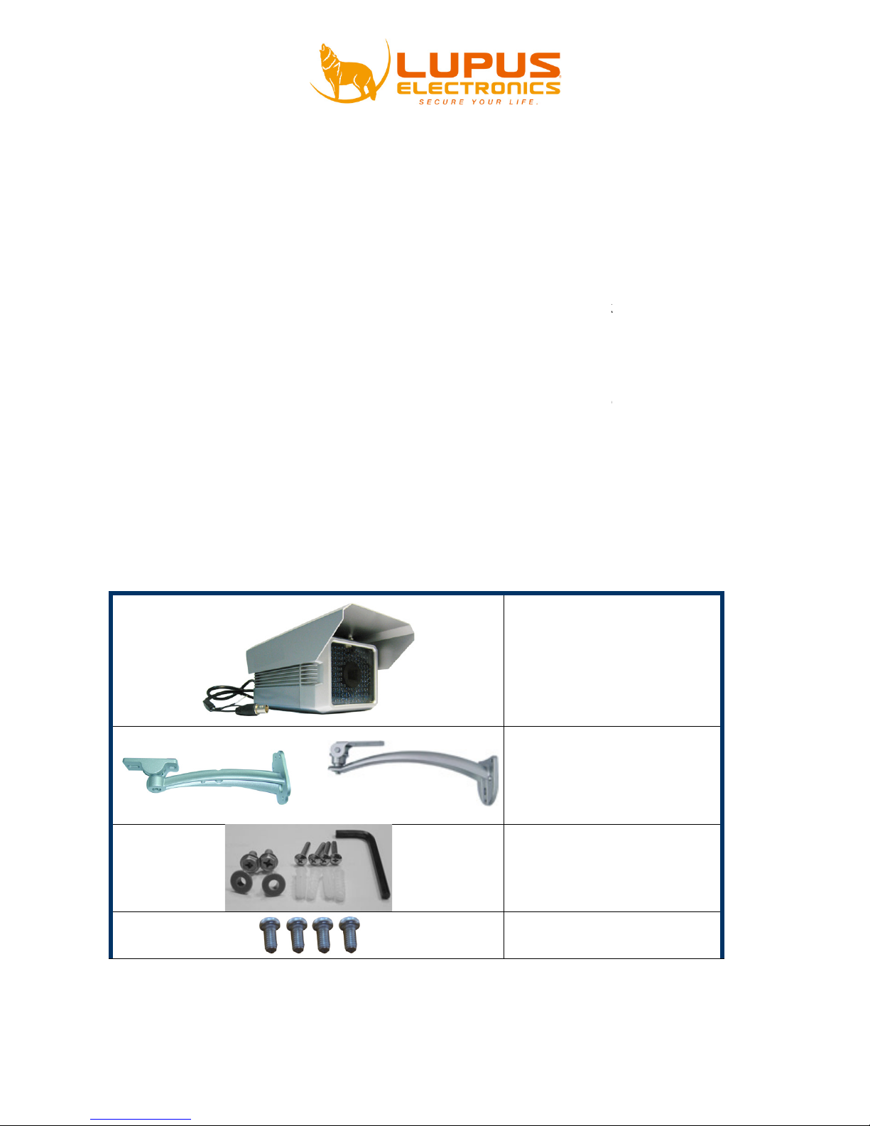
Lieferumfang :
OR
:
-
Bauteile, die Kamera könnte beschädigt werden.
t in der Nähe von starken elektrischen Leitungen.
-
und Temperaturbedingungen.
Gefahr eines Brands oder eines
LUPUSNIGHT 308 x 1
Sonnenschutz x 1
Halterung 1
Inbus x 1
Schraube für Halterungx 6
Dübel x 4
Unterlegscheibe x 2
Schraube für
Sonnenschutz x 4

Benutzerhandbuch x 1
Installation
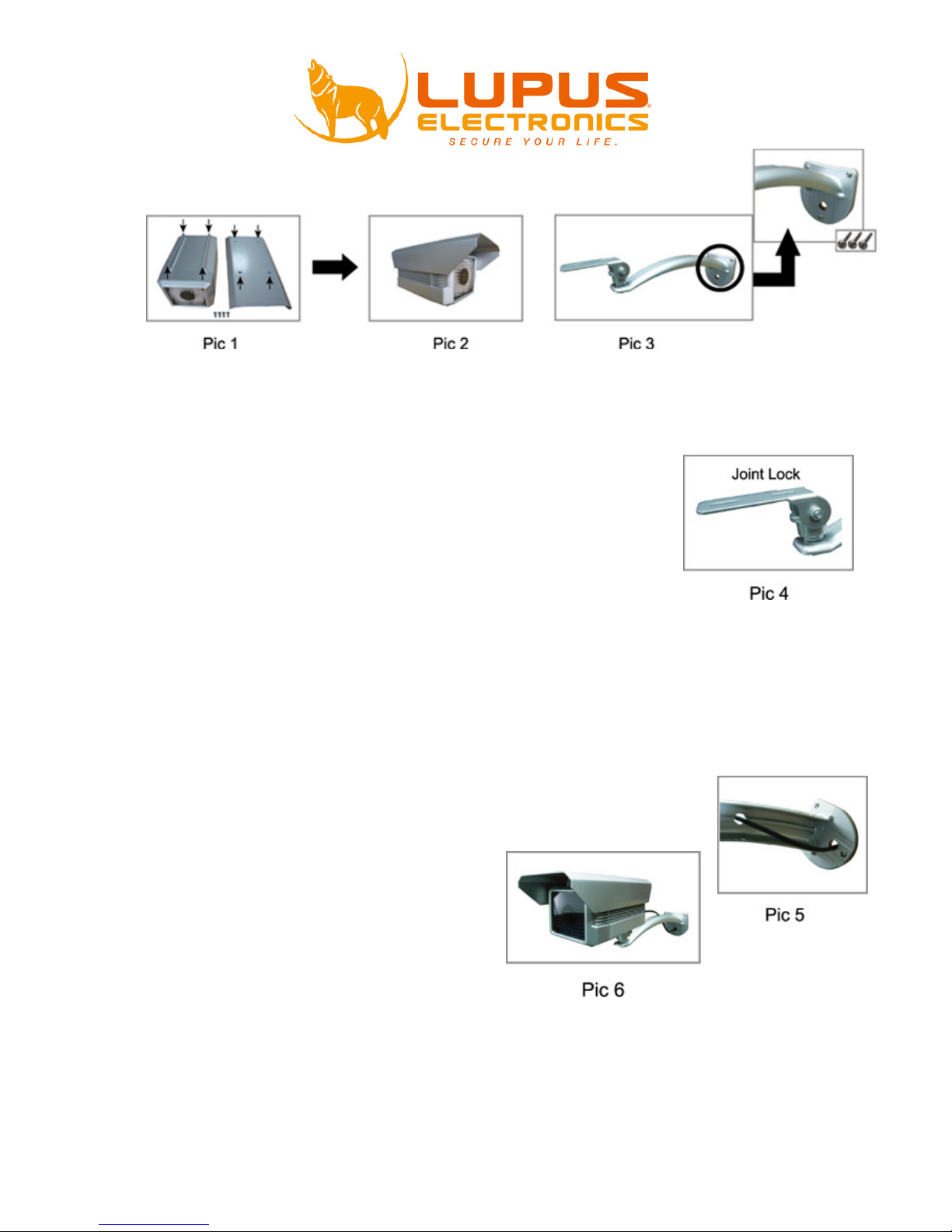
Schritt 1: Schrauben Sie das Sonnendach an die Kamera (Bild 1).
a) Verwenden Sie die für das Sonnendach passenden Schrauben aus der
beiliegenden Tüte
(Bild 1)
.
b) Auf der Kamera sehen Sie die 4 passenden Schraubenlöcher auf die das
Sonnendach montiert werden muss.
c) Schrauben Sie das Sonnendach mit den mitgelieferten Schrauben fest
(Bild 2).
Schritt 2: Schrauben Sie die Wandhalterung an die Wand (Bild 3).
d) Verwenden Sie die für die Halterung passenden Schrauben aus der beiliegenden
Tüte.
e) Montieren Sie die Halterung mit den Dübeln an der Wand
(Bild 3).
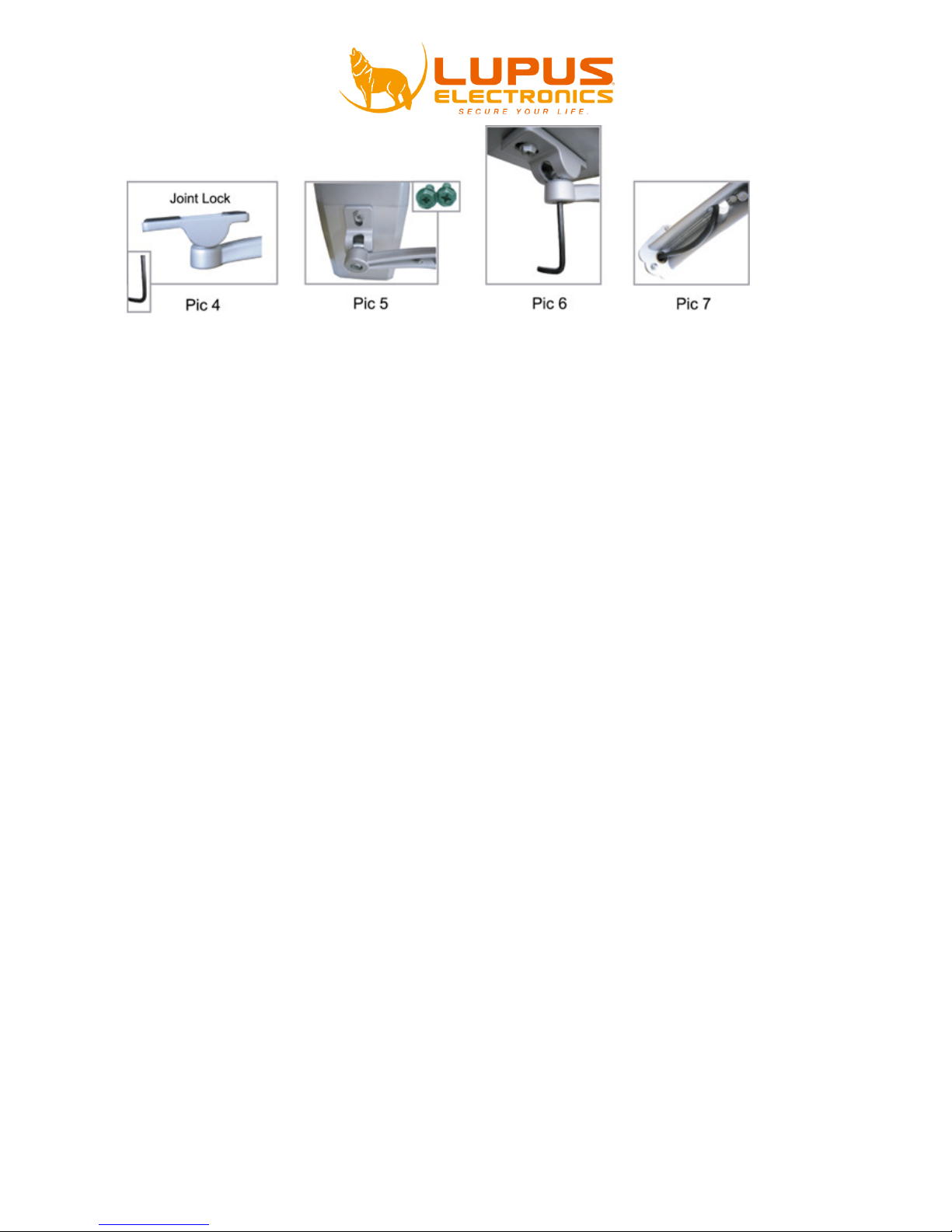
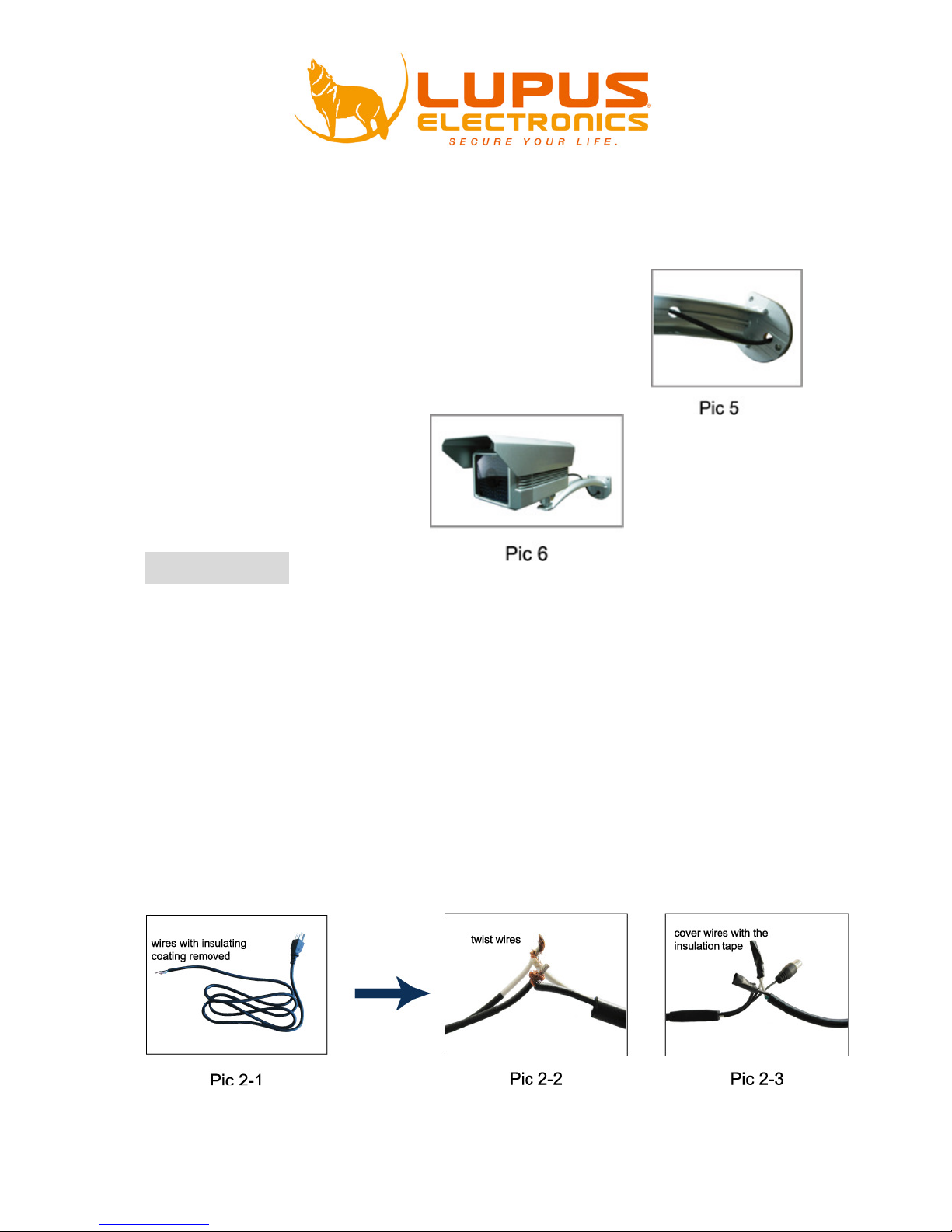
Schritt 3: Halterung an der Kamera anbringen (Bild 4+5).
f) Verwenden Sie den mitgelieferten Inbusschlüssel um die Schraube (
Bild 4
) an der
Unterseite zu lockern.
g) Drehen Sie die Halterung wie in Bild 5 zu sehen ist zur Seite. Diese Position
erleichtert das Anschrauben an die Kamera.
h) Schrauben Sie nun die mitgelieferten Schraben an die Kamera5.
i) Richten Sie die Kamera aus und ziehen Sie dann die Inbusschraube wieder fest.
Schritt 4: Führen Sie die Kabel wie in Bild 7 zu sehen durch die Öffnungen am Kamerafuß
Verbindung
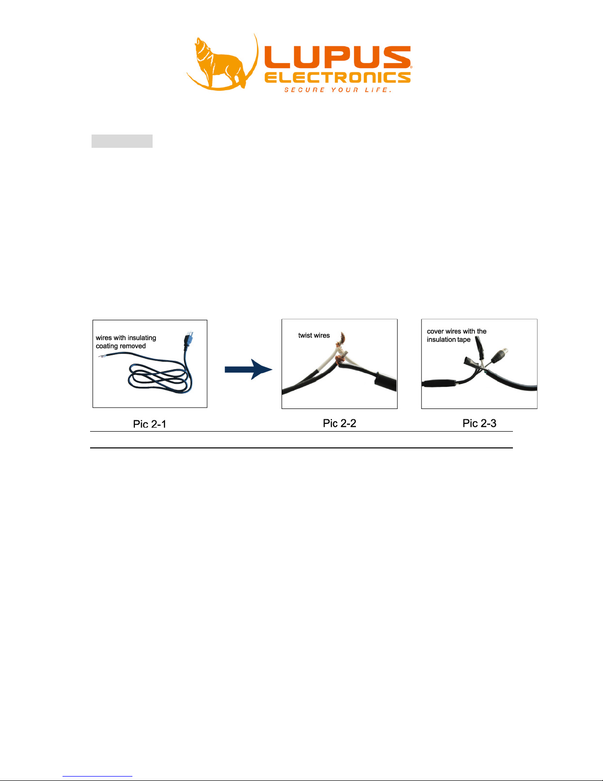
Schritt 1: Verbinden Sie den Videoausgang der Kamera mit einem RG59 Kabel.
Schritt 2: Verbinden Sie das Stromkabel mit einer 220/240V-Leitung.
a) Schneiden Sie die Stromleitung ab und legen Sie die Drähte (braun, blau,
gelb) frei. Bild 2-1.
b) Verwenden Sie eine Lüsterklemme oder andere geeignete Mittel um die
Drähte (braun, blau) sicher mit den beiden Stromkabeln der Kamera zu
verbinden.
c) Um die Verbindung zu schütze, verwenden Sie zB. einen wetterfesten
Aufputzkasten oder ähnliches Bild 9-3.
d) Schalten Sie den Strom ein.
HINWEIS: Diese Installation sollte nur von einer Fachkraft vorgenommen werden
Beschreibung
Diese neue innovative „IRpro“ Überwachungskamera wurde speziell für Umgebungen entwickelt, in
denen tagsüber wie nachts sehr schlechte Lichtverhältnisse vorherrschen aber ein Maximum an
Sicherheit und Erkennbarkeit gefordert ist. Die 102 High-End-LEDs der LE 308HP ermöglichen eine
Nachtsichtreichweite von bis zu 50 Metern. Ausgestattet mit einem neuartigen “IR Shifter”, der
innovativen “Smart Light Control-Technik” und einer großen Blende (F1.4), verbindet diese IRÜberwachungskamera scharfe und klare Bilder bei schlechtesten Lichtverhältnissen mit einer nie da
gewesenen Lebensdauer und Zuverlässigkeit. Die Advanced Night-Vision-Control regelt dabei optimal
und dynamisch die Stärke der Ausleuchtung je nach vorherrschenden Lichtverhältnissen.
Die im Wetterschutzgehäuse verbaute Kamera mit hoch auflösendem Sony® DSP CCD Chip liefert
480TV-Linien bei 752x582 Pixel. Das für die Kamera entworfene und vandalensichere Schutzgehäuse
(Schutzklasse IP67) wird mit 220V betrieben, ein 12V Spannungswandler für die Kamera ist integriert.
Die eingebaute Heizung schützt bei Temperaturschwankungen und hoher Luftfeuchtigkeit vor
Beschlagen und garantiert gleich bleibende Qualitätsaufnahmen. Dabei ist die Technik der Kamera
vor Hitze oder Kälte optimal geschützt. Ein massiver Wandhalter mit Schwenkgelenk ist im
Lieferumfang enthalten.

Technische Daten
• Sensor der Überwachungskamera: 1/3‘‘ Sony® DSP CCD
• Auflösung: 480 TV-Linien
• Lichtempfindlichkeit: 0,36 Lux (F1.2)
• Maximale Nachtsichtreichweite: 50 Meter (102 LEDs)
• IR Technik: IRPro®
• Integrierte Heizung
• Automatische Umschaltung auf S/W-Betrieb bei unter 1.0 Lux
• Automatische Verstärkerregelung (AGC)
• Automatischer Weißabgleich (AWB)
• Gegenlichtkompensation (BLC)
• Kontrastrate 400:1
• Digitale Bildverarbeitung (DSP)
• Mechanisch schwenkbarer IR-Filter mit Tag-/ Nachtumschaltung
• 8 mm Brennweite (ca. 42°)
• Spannung/Leistung: 220V
• 12V Spannungswandler im Gehäuse integriert
• Stromverbrauch max. 22W
• Massive Decken-/Wandhalterung im Lieferumfang
• Gewicht: 1.92kg
• Maße:220x125x115 (L)x(B)x(H)
• Schutzklasse: IP67
• Zertifizierungen: CE EMC, FCC CLASS A, RoHs, IP67
• Massive wall mount with rotatable joint included.
• Weight: 1.92kg
• Dimensions: 220x125x115 (L)x(W)x(H)
• Safety class: IP67
• Certifications: CE EMC, FCC CLASS A, RoHs, IP67

LUPUS-Electronics® GmbH
Lise-Meitner-Str.20, D-76829 Landau
Tel. +49 (0) 6341 93 55 3 0 Fax. +49 (0) 6341 93 55 3 20
E-Mail: info@Lupus-Electronics.de
www.Lupus-Electronics.de

LUPUSNIGHT®
LE-308
Manuel de l’Utilisateur

CCAAUUTTIIOONN:
:
To reduce the risk of electric shock, do not expose this apparatus to rain or moisture.
Only operate this apparatus from the type of power source indicated on the label.
The company shall not be liable for any damages arising out of any improper use, even if we have
been advised of the possibility of such damages.
CCAAUUTTIIOONN
RRIISSKK OOFF EELLEECCTTRRIICC SSHHOOCCKK
Merci d’avoir acheté un de nos produits Lupus-Electronics. Avant d'utiliser ce produit,
veuillez lire attentivement ce manuel d'instructions pour assurer la meilleure
utilisation de votre produit.
PRÉCAUTION IMPORTANTE :
Cette caméra est à brancher directement sur des fils
électriques 220V (vous pouvez aussi utiliser un adaptateur
secteur 24V ;1,5Ampères minimum mais nous conseillons
la solution sur câbles 220V)
Si vous n’avez aucune notion d’électricité, veuillez
confier l’installation à une personne qualifiée.
Si vous avez les notions d’électricité nécessaires à
l’installation de votre caméra, référez-vous aux instructions
de ce manuel pour monter votre caméra de façon optimale.
Ce produit est conforme avec la Directive 2002/95/EC du Parlement et
du Conseil Européen du 27 Janvier 2003 liée à la restriction de
l’utilisation des substances nuisibles dans les équipements électriques
et électroniques(RoHS) et ses amendements.
La Directive WEEE
c
oncernant les déchets des équipemen
entrée en vigueur le 13
un changem
ent important dans
fi n de vie.
Si le logo WEEE logo (situé à gauche) est apposé sur le
produit ou sur la boîte, il ne peut pas être jeté avec les
de la maison. Pour plus d’informations sur le traite
des produits électriques et les
service municipal
votre équipement.
Marque CE
Cet appareil est fabriqué pour se conformer aux interférence
La société ne garantit pas que ce manuel
nous réservons le droit de réviser ou de retirer tout
contenu de
ce manuel à n'importe quel moment.
Précautions:
1.
Lisez attentivement la notice avant u
2.
Avant de nettoyer la caméra, veillez à ce que celle
3.
Ne touchez pas la surface du capteur. Utilisez un chiffon doux imbibé d'alcool
pour nettoyer la surface si elle est touchée accidentellement.
4. Veillez
à ce que la tension d'
5.
Ne pas stocker l'appareil dans l'emplacement suivant
•
Lieux extrêmement chauds ou froids (la température de fonctionnement est
de -10 ~ 50 degrés)
•
À proximité de sources ou de champs magnétique
•
Près de puissants rayonnemen
•
Lieux trop humides ou poussiéreux
•
Près de lampes fluorescentes ou des objets reflétant une forte lumière
•
Sources lumineuses trop variable (cela pouvant causer un scintillement)
6.
Évitez au maximum le contact direct avec le soleil.
7. Ne
pas utiliser dans un endroit humide.
8.
Ne pas placer au dessus d’un radiateur ou autre source de chaleur.
9.
Installer la caméra sur un mur ou un plafond solide, ne pas installez sur des
surfaces molles, au risque de faire tomber la caméra
-Waste Elect
rical and Electronic Equipment
ts électriques et électroniques
Février 2003 dans la Loi Européenne a généré
le traitement des produits électriques en
ment et les déchets
points de collecte, merci de contacter le
des déchets ou le point de vente où vous avez acheté
soit
exempt d'erreurs. Nous
tilisation.
-
ci soit débrancher.
alimentation soit correcte.
:
ts électromagnétiques
,
autres déchets
s radio.
ou une partie du

Description
Cette nouvelle approche novatrice "IRpro" de caméra de surveillance a été
spécialement conçue pour les environnements de haute sécurité avec de mauvaises
conditions d'éclairage de jour comme de nuit. Sa haute résolution Sony ® DSP CCD
fournit 480 lignes TV à 752x582 pixels. Pas moins de 102 voyants (LED) permettent
une couverture de la vision de nuit de 50 mètres. Equipée des technologies "IR
Shifter" et "Smart Light Control" ainsi que d'une grande ouverture (F1.4), cette
caméra de surveillance des images IR incroyables dans la plupart des conditions
d'éclairage difficiles avec une durabilité et une fiabilité absolue. Le système
dynamique "Advanced Night Vision Control" ajuste l'intensité de la lumière en
fonction des conditions d'éclairage disponible à portée de main. Le boitier logement
de la caméra est spécifiquement conçus contre le vandalisme (classe de sécurité IP
67) et est alimenté par un câble 220 V, et un adaptateur 12 V est déjà intégré. La
technologie est parfaitement protégée de la chaleur et du froid. Un chauffe-eau
protège l'appareil contre les variations de température et de la formation de buée à
haut taux d'humidité et garantit ainsi une vidéo de haute qualité des transmissions en
toutes circonstances. Un grand support mural avec rotation est inclus.
*La couverture maximale de nuit dépend de l'objet observé et peut varier légérement
Spécifications Techniques
•
Capteur CCTV: 1/3" Sony® DSP CCD
•
Résolution: 480 lignes TV
•
Eclairage minimum requis: 0,36 Lux (F1.2)
•
Couverture maximale de vision de nuit: 50 mètres (102 LEDs)
•
Technologie IR: IRPro®
•
Chauffe eau et ventilateur intégrés
•
Bascule automatiquement en mode n&b en dessous de 1.0 Lux
•
Contrôle automatique de gain (AGC)
•
Balance des blancs automatique (AWB)
•
Compensation automatique de rétro-éclairage (BLC)
•
Taux de contraste 400:1
•
Processus d'image numérique ( DSP)
•
Ajustement filtre IR avec bascule automatique du mode Jour/Nuit
•
8 mm de largeur focale ( 42°)
•
Voltage: 220V
•
Adaptateur secteur 12V inclus dans le boitier
•
Consommation électrique: 22W max.
•
Fixation murale solide avec rotation inclus
•
Poids: 1.92kg
•
Dimensions: 220x125x115 (L) x (l) x (h)
•
Classe sureté: IP67
•
Certifications: CE EMC, FCC CLASS A, RoHs, IP67

Contenu
OR
Assurez-vous que tou
s les éléments indiqués ci
Kit. Si un élément
venait à manquer
possible.
La caméra LUPUSNIGHT®
LE308
Et le cache à fixer au dessus
1 support de fixation
4 vis et 4 chevilles
2 écrous
Une clé Allen (BTR)
1 manuel de l‘utilisateur
-dess
us sont inclus dans votre
, contactez votre
revendeur le plus tôt
–
4 écrous

Installation de la caméra
Choisissez l’emplacement où vous souhaitez installer votre camera détecteur de
mouvement. Cet emplacement est sans doute stratégique et se situe là où il y a un
risque potentiel d’y croiser voleurs ou autre risqué à surveiller.
Éteignez l’électricité générale du site où vous installez la caméra puis reliez les
câbles électriques comme expliqué dans le paragraphe suivant.
Étape 1:
Fixer le cache pare-soleil sur la caméra
a) Trouver la caméra, le cache pare-soleil et 4 écrous spécifiques fournies dans le
coffret de vente (Voir photo 1).
b) Il ya 4 trous pour les vis sur la caméra et le pare-soleil, comme indiqué sur le
dessin 1. Placez le pare-soleil sur la caméra et vissez les 4 vis.
c) une fois fixer, la caméra va ressembler à celle de la Photo 2.
Étape 2:
Fixer le support au mur (voir Photo 3).
a) Trouvez le support et 4 vis fournies dans l'emballage de vente.
b) Fixer le support sur le mur avec les 3 vis comme montré sur le dessin 3.
Étape 3:
Fixez l'appareil sur le support.
a) Utilisez un tournevis pour desserrer le verrou commun (voir Photo 4).
b) Trouver les deux trous de vis sur le bas de la caméra, et aligner les trous avec les
trous de vis sur le support de fixation et fixer la caméra à l’aide des 2 vis.
Étape 4:
Ajustez l'angle de caméra et assurez vous de bien serrer une fois l’angle choisi.
a) Ajuster la position de la caméra à l'angle approprié.
b) Utilisez le tournevis pour assurer le verrouillage et fixer l'angle de caméra.
Étape 5:
Faites glisser à l’endroit prévu le câble de caméra (Voir Pic 5).
a) Passez le câble de la caméra à travers les deux trous sur le
support.
b) Faire passer le câble dans le trou foré pour le cacher (le cas
échéant).
Étape 6:
Terminer l'installation (voir Pic 6).
Connection
ETAPE 1:
Connectez la sortie de la caméra vidéo et l'entrée vidéo du moniteur avec un câble
coaxial 75Ω.
ETAPE 2: Connectez l'appareil à l'alimentation électrique adéquate.
a) se procurer un cordon d'alimentation adéquate et couper le connectique femelle.
Retirez le revêtement isolant pour révéler deux fils comme le montre le Pic 2-1.
b) Mélanger ces deux fils avec les fils correspondants sur l'appareil photo comme
indiqué dans Pic 2-2. Il est recommandé d’utiliser un « sucre » et de visser les fils sur
ce dernier. Vous trouverez cela dans n’importe quel magasin de bricolage-électricité.
c) Pour protéger les fils nus, utilisez le ruban isolant à couvrir sur les fils tordus
comme le montre le Pic 2-3. (sauf si vous avez utilisé un sucre, cette étape n’est
alors pas nécessaire).
d) Brancher la connectique mâle du cordon d'alimentation dans la prise de courant.

Votre mémo
LUPUS-Electronics® GmbH
Lise-Meitner-Str.20, D-76829 Landau
Tel. +49 (0) 6341 93 55 3 0 Fax. +49 (0) 6341 93 55 3 20
E-Mail: info@Lupus-Electronics.de
www.Lupus-Electronics.fr
LUPUSNIGHT®
LE-308
User Manual
CCAAUUTTIIOONN:
:
To reduce the risk of electric shock, do not expose this apparatus to rain or moisture.
Only operate this apparatus from the type of power source indicated on the label.
The company shall not
be liable for any damages arising out of any improper use, even if we have
been advised of the possibility of such damages.
R
R
IMPORTANT SAFEGUARD
The lightning flash with arrowhead symbol, within an equilateral
triangle, is intended to alert the user to the presence of uninsulated
“dangerous voltage” within the product’s enclosure that may be of
sufficient magnitude to constitute a risk of electric
This exclamation point within an equilateral triangle is intended to alert
the user to the presence of important operating and maintenance
(servicing) instructions in the literature accompanying the appliance.
ROHS Announcement
All lead-
free products offered by the company comply with the
requirements of the European law on the Restriction of Hazardous
Substances (RoHS) directive, which means our manufacture
processes and products are strictly “lead
hazardous su
bstances cited in the directive.
The crossed-
out wheeled bin mark symbolizes that within the
European Union the product must be collected separately at the
product end-
of
marked with this symbol. D
unsorted municipal waste.
CE Mark
This apparatus is manufactured to comply with the radio interference.
The company does not warrant that this manual will be uninterrupted or
error-
free. We reserve the right to
manual at any time
CCAAUUTTIIOONN
IISSKK OOFF EELLEECCTTRRIICC SSHHOOCCKK
shock to persons.
-
free” and without the
-
life. This applies to your product and any peripherals
o not dispose of these products as
revise or remove any content in this
.

Hinweise zur Benutzung und Installation:
• Richten Sie die Kamera nicht direkt in die Sonne
• Richten Sie die Kamera nie direkt in ein Spotlicht
• Behandeln Sie die Kamera behutsam, starke Vibrationen oder Stöße können
die Kamera beschödigen.
• Berühren Sie niemals Interne-Bauteile, die Kamera könnte beschädigt
werden.
• Installieren Sie die Kamera nicht in der Nähe von starken elektrischen
Leitungen. Dies könnte die Bildqualität beeinträchtigen.
• Installieren Sie die Kamera nicht direkt auf einen Aluminium oder Eisenmast
ohne den Fuß der Kamera mit einer Gummierung von dem Mast zu isolieren.
Das Kamerabild könnte gestört werden.
• Beachten Sie die max. Feuchtigkeits- und Temperaturbedingungen.
*Sollten Sie Fehler feststellen
Falls Fehler auftreten sollten, ziehen Sie den Strom der Kamera und kontaktieren
Sie Ihren Lieferanten. Weitere Benutzung erhöht die Gefahr eines Brands oder
eines elektrischen Schlags.

Shipment :
OR
Installation
STEP 1:
Assemble the camera and sun shield (see Pic 1 and Pic 2).
a)
Find the camera, sun shield and 4 sun
sales package (Pic 1).
b)
There are 4 screw holes separately on the camera and the sun shield as
indicated in Pic 1. Put th
holes.
c)
Secure the sun shield onto the camera with the supplied 4 screws.
camera will look like Pic 2.
102-
unit IR Camera x 1
Sun Shield x 1
Bracket x 1
Wrench x 1
Screw for Bracket x 6
Wall Plug x 4
Pad for Screw x 2
Screw for Sun Shield x 4
User Manual x 1
-shield-
specific screws supplied in your
e sun shield onto the camera and align these 4 screw
The
STEP 2: Attach the bracket to the wall (See Pic 3).
a) Find the bracket and 4 screws supplied in the sale package.
b) Fasten the bracket onto the wall with the 3 screws as shown in Pic 3.
STEP 3: Attach the camera to the bracket.
a) Use a screwdriver to loosen the joint lock (see Pic 4) from
the bottom.
b) Move up the platform of the joint lock for this position is
convenient for you to lock and secure the camera.
c) Find the two screw holes on the bottom of the camera, and
align the holes with the screw holes on the platform of the
joint lock.
d) Fasten the camera to the joint lock with screws.
STEP 4: Adjust the camera angle and secure the joint lock to fix.
a) Adjust the camera position to the proper angle.
b) Use the screwdriver to secure the joint lock, and fix the camera angle.
STEP 5: Arrange the camera cable (See Pic 5).
a) Pass the camera cable through the two holes on the bracket.
b) Pass the cable to the hole drilled for hiding it (if any).
STEP 6: Finish the installation (See Pic 6).

Connection
STEP 7: Connect the camera video output and the monitor video input with a 75Ω
coaxial cable.
STEP 8: Connect the camera to proper power supply.
e) Get a proper power cord and cut off the female connector. Remove the
insulating coating to reveal two wires as shown in Pic 9-1.
f) Twist these two wires with the corresponding wires on the camera as shown in
Pic 9-2.
g) To protect the naked wires, use the insulation tape to cover on the twisted
wires as shown in Pic 9-3.
h) Connect the male connector of the power cord into the power socket.
NOTE: Please connect to the correct power supply to operate this unit. Over maximum power input will damage
this unit.
Description
This new innovative "IRpro" surveillance camera was specifically developed for maximum security
environments with bad lighting conditions both by day and at night. Its high resolution Sony® DSP
CCD chip delivers 480 TV-lines at 752x582 pixels. 102 High-End-LEDs allow for a night vision
coverage of 50 meters. Equipped with its groundbreaking "IR Shifter" and "Smart Light Control"
technologies as well as a large aperture (F1.4), this IR-surveillance camera combines incredibly sharp
images under most difficult lighting conditions with amazing durability and absolute reliability. The
"Advanced Night Vision Control" system dynamically regulates the required illumination intensity
according to lighting conditions at hand. The specifically designed weather- and vandal-proof housing
(safety class IP 67) is powered by a 220V cable, a 12 V adapter is already integrated. The technology
is perfectly shielded from heat and cold. A built-in heater protects the camera against temperature
variations and fogging at high humidity conditions and thus guarantees constant high quality video
transmissions. A massive wall mount with rotatable joint is included.

Technical Specifications
• CCTV camera sensor: 1/3‘‘ Sony® DSP CCD
• Resolution:: 480 TV-Linien
• Min. illumination: 0,36 Lux (F1.2)
• Max. night vision coverage: 50 meters (102 LEDs)
• IR technology: IRPro®
• Integrated heater
• Automatically switches to b/w mode at under 1.0 Lux
• Automatic gain control (AGC)
• Automatic white balance (AWB)
• Automatic backlighting compensation (BLC)
• Contrast rate: 400:1
• Digital image processing (DSP)
• Electromechanically adjusted IR-filter with automatic day/night-shifting
• 8 mm focal width (ca. 42°)
• Voltage: 220V
• 12V adapter integrated into housing
• Power consumption max. 22W
• Massive wall mount with rotatable joint included.
• Weight: 1.92kg
• Dimensions: 220x125x115 (L)x(W)x(H)
• Safety class: IP67
• Certifications: CE EMC, FCC CLASS A, RoHs, IP67

Memo :
LUPUS-Electronics® GmbH
Lise-Meitner-Str.20, D-76829 Landau
Tel. +49 (0) 6341 93 55 3 0 Fax. +49 (0) 6341 93 55 3 20
E-Mail: info@Lupus-Electronics.de
www.Lupus-Electronics.com
 Loading...