

Page 1

xPONENT for MAGPIX 4.2
Software User Manual
Page 2

©
Luminex Corporation, 2011. All rights reserved. No part of this publication may be
reproduced, transmitted, transcribed, or translated into any language or computer language,
in any form or by any means without prior express, written consent of Luminex Corporation.
LUMINEX CORPORATION
12212 Technology Boulevard
Austin, Texas 78727-6115
U.S.A.
Voice: (512) 219-8020
Fax: (512) 219-5195
xPONENT 4.2 for MAGPIX Software User Manual
89-00002-00-239 rev. E
November 2011
Luminex Corporation (Luminex) reserves the right to modify its products and services at any
time. This guide is subject to change without notice. Although prepared to ensure accuracy,
Luminex assumes no liability for errors or omissions, or for any damages resulting from the
application or use of this information.
The following are trademarks of Luminex Corporation: Luminex®, xMAP®, xTAG®,
xPONENT®, Luminex® 100™, Luminex® 100 IS®, Luminex® 200™, Luminex® SD™, Luminex
®
XYP™, MagPix®, MagPlex® Microspheres, MicroPlex®.
All other trademarks, including ProClin®, Cheminert®, Windows® Pentium® and Dell® are
trademarks of their respective companies.
i
Page 3

End-User License Agreement (EULA) for Luminex
xPONENT® Software
This Luminex End-User License Agreement (“EULA”) is a legal agreement between you
(either an individual or a single entity, also referred herein as “you”) the end-user and
Luminex Corporation (“Luminex”) regarding the use of the xPONENT software product
provided to you above, which includes computer SOFTWARE and online or electronic
documentation and may include associated media and printed materials (if any)
(“SOFTWARE”). The terms also apply to any updates, supplements, web content or internetbased services, such as remote access.
BY USING THE SOFTWARE, YOU ACCEPT THESE TERMS. IF YOU DO NOT ACCEPT
THEM, DO NOT USE THE SOFTWARE. INSTEAD, RETURN IT TO LUMINEX OR THE
LUMINEX AUTHORIZED THIRD PARTY FROM WHICH YOU PURCHASED THE
SOFTWARE FOR A REFUND OR CREDIT. IF YOU COMPLY WITH THESE LICENSE
TERMS, YOU HAVE THE RIGHTS TO USE THE SOFTWARE AS SPECIFICALLY SET
FORTH BELOW.
1. OVERVIEW. The SOFTWARE is protected by copyright laws and international copyright
treaties, as well as other intellectual property laws and treaties. The SOFTWARE is
licensed, not sold.
2. ADDITIONAL LICENSING REQUIREMENTS AND/OR USE RIGHTS.
a. Trial and Conversion. Some or all of the SOFTWARE may be licensed on a trial basis.
Your rights to use trial SOFTWARE are limited to the trial period. The trial SOFTWARE
and length of the trial period are set forth during the activation process. The
SOFTWARE may be used for evaluation purposes only during the trial period and not
for any commercial use, including without limitation to any diagnostic use. You may
have the option to convert your trial rights to perpetual rights. Conversion options will
be presented to you at the expiration of your trial period.
b. Activation. You can activate the SOFTWARE by obtaining a license key provided by
Luminex Technical Support at support@luminexcorp.com or 1-877-785-2323 or
1-512-381-4397.
c. Branding. You may only add additional branding or other graphics to SOFTWARE with
Luminex's express written consent.
d. Upgrades. You may only obtain updates or upgrades for the SOFTWARE from
Luminex Technical Support at orders@luminexcorp.com or authorized resellers. For
more information on obtaining updates from authorized resellers, see http://
www.luminexcorp.com.
®
xPONENT for MAGPIX 4.2 Software User Manual
ii
Page 4

3. GRANT OF LICENSE. Subject to the terms and conditions of this EULA, Luminex hereby
grants to you a nonexclusive, nontransferable, nonassignable license (without right to
sublicense) under Luminex's copyrights and trade secrets to use the SOFTWARE on a
single computer running with a single unit of a specific model of Luminex instrument, as
such model is identified on the packaging included with the SOFTWARE. You may make
one (1) copy of the SOFTWARE for backup or archival purposes only. You may also
install the SOFTWARE on up to two (2) additional computers for purposes of performing
ancillary tasks (i.e. preparing templates/protocols, performing further analysis or rerunning previous data), provided such computers are at a single location and are NOT
connected with a Luminex instrument. In addition, You may purchase the right to use the
SOFTWARE on additional computers, as agreed to in writing with Luminex or its
authorized reseller, for purposes of performing ancillary tasks (i.e. preparing templates/
protocols, performing further analysis or re-running previous data), provided such
computers are at a single location and are NOT connected with a Luminex instrument.
Although no rights or licenses under any of Luminex's patents are granted by or shall be
implied from the license of the SOFTWARE or the sale of Luminex instrumentation to
you, the purchaser, you may obtain a license under Luminex's patents, if any, to use this
unit of Luminex instrumentation with fluorescently labeled microsphere beads authorized
by Luminex by purchasing such beads from Luminex or an authorized Luminex reseller.
4. RESTRICTIONS
• SOFTWARE must only be installed and operated on a single computer running with a
Luminex instrument, as set forth above.
• You may not use this SOFTWARE for any commercial purpose, including in the
performance of testing services, unless expressly agreed to in writing by Luminex or as
authorized in writing by Luminex through an authorized reseller of the SOFTWARE.
• You may only use the SOFTWARE with microspheres manufactured by Luminex or
with kits developed, manufactured and distributed by licensees authorized in writing by
Luminex.
• You must maintain all proprietary notices on all copies of the SOFTWARE.
• You may not distribute copies of the SOFTWARE to third parties.
• You may not reverse-engineer, decompile, disassemble, or otherwise attempt to derive
source code from the SOFTWARE.
• You may not copy (other than one backup or archival copy), distribute, sublicense,
rent, lease, transfer or grant any rights in or to all or any portion of the SOFTWARE.
• You must comply with all applicable laws regarding the use of the SOFTWARE.
• You may not modify or prepare derivative works of the SOFTWARE, including
modifying any branding or graphics.
• You may not use the SOFTWARE in a computer-based service business or publicly
display visual output of the SOFTWARE.
• You may not transmit the SOFTWARE over a network, by telephone, or electronically
by any means.
iii
Page 5

5. TERM AND TERMINATION. Your rights under this EULA are effective until termination.
You may terminate this EULA at any time by destroying the SOFTWARE, including all
computer programs and documentation, and erasing any copies residing on your
computer equipment. Luminex may terminate this EULA upon thirty (30) days written
notice to you. Your rights under this EULA automatically terminate without further action
on the part of Luminex if you do not comply with any of the terms or conditions of this
EULA. Upon any termination of this EULA, you agree to destroy the SOFTWARE and
erase any copies residing on your computer equipment.
6. RIGHTS IN SOFTWARE. All rights and title in and to the SOFTWARE and any copies
thereof are owned by Luminex or its suppliers. This EULA is not a sale and does not
transfer to you any title or ownership interest in or to the SOFTWARE or any patent,
copyright, trade secret, trade name, trademark or other intellectual property right therein.
You shall not remove, alter, or obscure any proprietary notices contained on or within the
SOFTWARE and shall reproduce such notices on any back-up copy of the SOFTWARE.
All title and intellectual property rights in and to the content which may be accessed
through use of the SOFTWARE is the property of the respective content owner and may
be protected by applicable copyright or other intellectual property laws and treaties. This
EULA grants you no rights to use such content.
7. EXPORT RESTRICTIONS. You agree that you will not export or re-export the
SOFTWARE to any country, person, entity, or end-user subject to U.S.A. export
restrictions. You hereby warrant no state or federal agency has suspended, revoked, or
denied your export privileges.
8. NO WARRANTY. THE SOFTWARE IS LICENSED "AS IS." ANY USE OF THE
SOFTWARE IS AT YOUR OWN RISK. THE SOFTWARE IS PROVIDED FOR USE
ONLY WITH LUMINEX PRODUCTS. TO THE MAXIMUM EXTENT PERMITTED BY
APPLICABLE LAW, LUMINEX AND ITS SUPPLIERS DISCLAIM ALL WARRANTIES,
EITHER EXPRESS OR IMPLIED, INCLUDING, BUT NOT LIMITED TO, IMPLIED
WARRANTIES OF MERCHANTABILITY, FITNESS FOR A PARTICULAR PURPOSE,
AND NONINFRINGEMENT.
9. LIMITATION OF LIABILITY. IN NO EVENT SHALL LUMINEX OR ITS SUPPLIERS BE
LIABLE FOR ANY SPECIAL, INCIDENTAL, INDIRECT, OR CONSEQUENTIAL
DAMAGES WHATSOEVER (INCLUDING, WITHOUT LIMITATION, DAMAGES FOR
LOSS OF BUSINESS PROFITS, BUSINESS INTERRUPTION, LOSS OF BUSINESS
INFORMATION, OR ANY OTHER PECUNIARY LOSS) ARISING OUT OF THE USE OF
OR INABILITY TO USE THE SOFTWARE, EVEN IF LUMINEX HAS BEEN ADVISED OF
THE POSSIBILITY OF SUCH DAMAGES.
10. MISCELLANEOUS. This EULA is governed by the laws of the State of Texas, U.S.A.,
without reference to conflicts of laws principles. You shall not assign or sublicense or
otherwise transfer the rights or license granted hereunder, by agreement or by operation
of law, without the prior written consent of Luminex, and all assignments in violation of
this prohibition shall be null and void. This EULA is the complete and exclusive
agreement of Luminex and you and supersedes all other communications, oral or written,
relating to the subject matter hereof. No change to this EULA shall be valid unless in
writing and signed by the party against whom enforcement is sought. The waiver or
failure of Luminex or you to exercise in any respect any right or rights provided for herein
shall not be deemed a waiver of any further right hereunder. If any provision of this EULA
is held unenforceable, the remainder of this EULA will continue in full force and effect.
89-30000-00-254 Rev. B
xPONENT for MAGPIX 4.2 Software User Manual
iv
Page 6

Standard Terms and Conditions for Use of Instrument
Product
By opening the packaging containing this product ("Product") or by using such Product in any
manner, you are consenting and agreeing to be bound by the following terms and conditions.
You are also agreeing that the following terms and conditions constitute a legally valid and
binding contract that is enforceable against you. If you do not agree to all of the terms and
conditions set forth below, you must promptly return the Product for a full refund prior to using
them in any manner.
1. Acceptance
ALL SALES ARE SUBJECT TO AND EXPRESSLY CONDITIONED UPON THE TERMS
AND CONDITIONS CONTAINED HEREIN, AND UPON BUYER'S ASSENT THERETO. NO
VARIATION OF THESE TERMS AND CONDITIONS SHALL BE BINDING UPON LUMINEX
CORPORATION ("LUMINEX") UNLESS AGREED TO IN WRITING AND SIGNED BY AN
AUTHORIZED REPRESENTATIVE OF LUMINEX. For purposes of this agreement, "Seller"
shall mean either Luminex, if the Product is purchased directly from Luminex, or a Luminex
authorized reseller. Buyer, by accepting the Product shall be deemed to have assented to the
terms and conditions set forth herein, notwithstanding any terms contained in any prior or
later communications from Buyer and whether or not Seller shall specifically or expressly
object to any such terms.
2. Warranties
THIS WARRANTY IS APPLICABLE FOR PARTS AND SERVICE FOR LUMINEX
INSTRUMENTS PURCHASED DIRECTLY FROM LUMINEX TO BUYER AND ONLY TO
THE EXTENT SUCH INSTRUMENTS ARE LOCATED IN NORTH AMERICA AND THE
COUNTRIES THAT COMPRISE THE EUROPEAN UNION. LUMINEX MAKES NO
WARRANTY, EITHER EXPRESS OR IMPLIED, WITH RESPECT TO PRODUCTS SOLD,
DISTRIBUTED, LOCATED OR USED OUTSIDE OF NORTH AMERICA OR THE
COUNTRIES COMPRISING THE EUROPEAN UNION. PRODUCTS SOLD OUTSIDE OF
NORTH AMERICA OR THE COUNTRIES COMPRISING THE EUROPEAN UNION ARE
SOLD ONLY ON AN "AS IS, WHERE IS" BASIS. NOTWITHSTANDING THE FOREGOING,
LUMINEX SHALL PROVIDE BUYER A WARRANTY ON FIELD SERVICE PARTS
PROCURED FROM LUMINEX FOR MAINTENANCE OF LUMINEX INSTRUMENTS IN ALL
COUNTRIES IN THE WORLD AND PER THE TERMS AND CONDITIONS HEREIN. TO
THE EXTENT THAT THE FOREGOING DISCLAIMERS ARE INVALID OR
UNENFORCEABLE UNDER THE LAWS OF ANY JURISDICTION, THE WARRANTY,
DISCLAIMER, LIMITATION OF LIABILITY AND OTHER PROVISIONS SET FORTH BELOW
SHALL THEREUPON BE EFFECTIVE TO THE FULLEST EXTENT PERMITTED BY
APPLICABLE LAW.
Notwithstanding Buyer's acceptance thereof, if Product is purchased directly from Luminex,
Luminex warrants that for a period of twelve (12) months from date of delivery that the
Product shall conform in all material respects with the Product Specifications provided by
Luminex with the Product. The warranty provided herein specifically excludes any software or
v
Page 7

hardware not provided by Luminex. If Product is purchased from a Luminex authorized
reseller, any warranty obligations shall be provided in writing directly by such Luminex
authorized reseller to Buyer. THIS WARRANTY IS EXCLUSIVE AND LUMINEX MAKES NO
OTHER WARRANTY, EXPRESS OR IMPLIED, INCLUDING WITHOUT LIMITATION ANY
IMPLIED WARRANTY OF MERCHANTABILITY OR FITNESS FOR A PARTICULAR
PURPOSE. Seller's warranties made in connection with this sale shall not be effective if
Seller has determined, in its sole discretion, that Buyer has misused the Product in any
manner, has failed to use the Product in accordance with industry standards or practices or
has failed to use the Product in accordance with instructions, if any, furnished by Seller.
BUYER'S EXCLUSIVE REMEDY WITH RESPECT TO PRODUCT PROVED TO SELLER'S
SATISFACTION TO BE DEFECTIVE OR NONCONFORMING SHALL BE REPAIR OR
REPLACEMENT OF SUCH PRODUCTS WITHOUT CHARGE OR REFUND OF THE
PURCHASE PRICE, IN SELLER'S SOLE DISCRETION, UPON THE RETURN OF SUCH
PRODUCTS IN ACCORDANCE WITH SELLER'S INSTRUCTIONS BELOW. NEITHER
SELLER NOR LUMINEX SHALL IN ANY EVENT BE LIABLE FOR INCIDENTAL,
CONSEQUENTIAL OR SPECIAL DAMAGES OF ANY KIND RESULTING FROM ANY USE
OR FAILURE OF THE PRODUCT, EVEN IF SELLER OR LUMINEX HAS BEEN ADVISED
OF THE POSSIBILITY OF SUCH DAMAGE INCLUDING, WITHOUT LIMITATION,
LIABILITY FOR LOSS OF WORK IN PROGRESS, DOWN TIME, LOSS OF REVENUE OR
PROFITS, FAILURE TO REALIZE SAVINGS, LOSS OF PRODUCTS OF BUYER OR
OTHER USE OR ANY LIABILITY OF BUYER TO A THIRD PARTY ON ACCOUNT OF
SUCH LOSS, OR FOR ANY LABOR OR ANY OTHER EXPENSE, DAMAGE OR LOSS
OCCASIONED BY SUCH PRODUCT INCLUDING PERSONAL INJURY OR PROPERTY
DAMAGE UNLESS SUCH PERSONAL INJURY OR PROPERTY DAMAGE IS CAUSED BY
SELLER'S GROSS NEGLIGENCE.
In the event that Product is located outside of North America or the European Union and fails
to conform to the warranty set forth herein, during the warranty period: (i) Buyer shall notify
Luminex in a timely manner in writing that such Product failed to conform and shall furnish a
detailed explanation of any alleged nonconformity; (ii) Buyer at it's expense will contract
either Luminex or a Luminex trained service engineer to assess the issue and identify the
defective FS-PART; and (ii) at Luminex's option and election, Buyer shall either return such
nonconforming Product to Luminex's manufacturing facility or destroy such Product and
provide Luminex with written certification of destruction. In the event that a FS-PART is
returned to Luminex's manufacturing facility, Luminex may analyze such FS-PART for
defects. In the event that Luminex determines that such FS-PART is not defective, the FSPART shall be shipped to Buyer then Buyer shall be responsible for the payment for such FSPART and related shipping charges. Furthermore, in the event that Luminex determines that
such FS-PART is defective then Luminex shall be responsible for the payment for such FSPART and related shipping charges. Except as expressly provided herein, Buyer shall not
have the right to return a Product to Luminex without Luminex's prior written consent.
3. Buyer's Use of Product
Buyer shall not use this Product for any commercial purpose, including without limitation
performance of testing services, unless expressly agreed to in writing by Luminex or as
specifically authorized by Luminex through a Luminex distributor. Buyer agrees that no rights
or licenses under Luminex's patents shall be implied from the sale of the Product, except as
expressly provided herein or as specifically agreed to in writing by Luminex, and Buyer does
not receive any right under Luminex's patent rights hereunder. Buyer acknowledges and
agrees that the Product are sold and licensed only for use with Luminex's laser based
fluorescent analytical test instrumentation. Buyer further acknowledges that, unless otherwise
xPONENT for MAGPIX 4.2 Software User Manual
vi
Page 8

indicated on the Product label, the Product has not received approval from the United States
Food and Drug Administration or other federal, state or local regulatory agencies and have
not been tested by Seller or Luminex for safety or efficacy in food, drug, medical device,
cosmetic, commercial or any other use, unless otherwise stated in Seller's technical
specifications or material data sheets furnished to Buyer. Buyer expressly represents and
warrants to Seller that Buyer will use the Product in accordance with the Product label, if
applicable, and will properly test and use any Product in accordance with the practices of a
reasonable person who is an expert in the field and in strict compliance with the United
States Food and Drug Administration and all applicable domestic and international laws and
regulations, now and hereinafter enacted.
BUYER HEREBY GRANTS TO LUMINEX A NONEXCLUSIVE, WORLDWIDE,
UNRESTRICTED, ROYALTY-FREE, FULLY PAID-UP LICENSE, WITH THE RIGHT TO
GRANT AND AUTHORIZE SUBLICENSES, UNDER ANY AND ALL PATENT RIGHTS IN
INVENTIONS COMPRISING MODIFICATIONS, EXTENSIONS, OR ENHANCEMENTS
MADE BY BUYER TO THE PRODUCT OR TO THE MANUFACTURE OR USE OF THE
PRODUCT ("IMPROVEMENT PATENTS"), TO MAKE, HAVE MADE, USE, IMPORT,
OFFER FOR SALE OR SELL ANY AND ALL PRODUCT; EXPLOIT ANY AND ALL
METHODS OR PROCESSES; AND OTHERWISE EXPLOIT IMPROVEMENT PATENTS
FOR ALL PURPOSES. NOTWITHSTANDING THE FOREGOING, "IMPROVEMENT
PATENTS" SPECIFICALLY EXCLUDES PATENT CLAIMS CONCEIVED AND REDUCED
TO PRACTICE BY BUYER CONSISTING OF METHODS OF SAMPLE PREPARATION,
METHODS OF CONJUGATING PRODUCT TO ANALYTES, THE COMPOSITION OF
MATTER OF THE SPECIFIC CHEMISTRIES OF THE ASSAYS DEVELOPED BY BUYER
AND METHODS OF PERFORMING THE ASSAYS (I.E., THE PROTOCOL FOR THE
ASSAY).
Buyer has the responsibility and hereby expressly assumes the risk to verify the hazards and
to conduct any further research necessary to learn the hazards involved in using the Product.
Buyer also has the duty to warn Buyer's customers, employees, agents, assigns, officers,
successors and any auxiliary or third party personnel (such as freight handlers, etc.) of any
and all risks involved in using or handling the Product. Buyer agrees to comply with
instructions, if any, furnished by Seller or Luminex relating to the use of the Product and not
misuse the Product in any manner. Buyer shall not reverse engineer, decompile, disassemble
or modify the Product. Buyer acknowledges that Luminex retains ownership of all patents,
trademarks, trade secrets and other proprietary rights relating to or residing in the Product
and Buyer receives no rights to such intellectual property rights by virtue of its purchase of
Product other than as expressly set forth herein. Buyer shall have no right to use any
trademarks owned or licensed to Luminex without the express written permission of Luminex.
4. Buyer's Representations, Release and Indemnity
Buyer represents and warrants that it shall use the Product in accordance with Paragraph 2,
"Buyer's Use of Product," and that any such use of Product will not violate any law,
regulation, judicial order or injunction. Buyer agrees to release, discharge, disclaim and
renounce any and all claims, demands, actions, causes of action and/or suits in law or equity,
now existing or hereafter arising, whether known or unknown, against Seller and Luminex,
and their respective officers, directors, employees, agents, successors and assigns
(collectively the "Released Parties"), with respect to the use of the Product. Buyer agrees to
indemnify and hold harmless the Released Parties from and against any suits, losses, claims,
demands, liabilities, costs and expenses (including attorney, accounting, expert witness, and
consulting fees) that any of the Released Parties may sustain or incur as a result of any claim
against such Released Party based upon negligence, breach of warranty, strict liability in tort,
vii
Page 9

contract or any other theory of law or equity arising out of, directly or indirectly, the use of the
Product or by reason of Buyer's failure to perform its obligations contained herein. Buyer shall
fully cooperate with the Released Parties in the investigation and determination of the cause
of any accident involving the Product which results in personal injury or property damage and
shall make available to the Released Parties all statements, reports, recordings and tests
made by Buyer or made available to Buyer by others.
5. Patent Disclaimer
Neither Seller nor Luminex warrants that the use or sale of the Product will not infringe the
claims of any United States or other patents covering the product itself or the use thereof in
combination with other products or in the operation of any process.
xPONENT for MAGPIX 4.2 Software User Manual
viii
Page 10

Table of Contents
Chapter 1 Introduction ........................................................................................................1
Safety Precautions .......................................................................................................................................1
Elements of the Software .............................................................................................................................1
Home Page ...........................................................................................................................................1
Screen Elements ...................................................................................................................................3
System Monitor .....................................................................................................................................4
Help .......................................................................................................................................................5
Quick Start .............................................................................................................................................6
System Info Tab ....................................................................................................................................6
Basic Procedures .........................................................................................................................................7
Starting xPONENT ................................................................................................................................7
Adding a New License Key ...................................................................................................................8
Logging On to xPONENT ......................................................................................................................8
Initial Startup .........................................................................................................................................9
Daily Activities .....................................................................................................................................13
Shutting Down the Analyzer ................................................................................................................13
Logging Off and Exiting .......................................................................................................................14
Using Online Help ...............................................................................................................................14
Luminex Support ........................................................................................................................................15
Luminex Website .................................................................................................................................15
Contacting Technical Support .............................................................................................................15
Software Packages ....................................................................................................................................15
MAGPIX Technology .................................................................................................................................16
Running Assays with MAGPIX ..................................................................................................................17
General Guidelines ..............................................................................................................................17
Biological Samples ..............................................................................................................................18
Bead (Microsphere) Handling ..............................................................................................................18
Repetitive MagPlex Bead Measurements ...........................................................................................18
Classification and Reporter Fluorochromes ........................................................................................19
Fluidics 1 and Fluidics 2 ......................................................................................................................19
Sample Volume ...................................................................................................................................19
Plates ..................................................................................................................................................20
Chapter 2 Samples Page ..................................................................................................23
Samples Page Functionality ......................................................................................................................23
Edit Samples and Create Sample Subtab .................................................................................................24
Creating a New Sample List ................................................................................................................25
Editing a Sample List ...........................................................................................................................27
Chapter 3 Batches Page ...................................................................................................29
Batches Page Functionality .......................................................................................................................29
Setting Up Batches ....................................................................................................................................30
Using the Batches Page ............................................................................................................................30
Create a New Batch from an existing Protocol ....................................................................................31
ix
Page 11

Create a New Batch from a New Protocol ...........................................................................................37
Create a New Multi-Batch ................................................................................................................... 50
Batch Procedures ......................................................................................................................................52
Running a Pending Batch ....................................................................................................................52
Importing a Batch ................................................................................................................................52
Exporting a Batch ................................................................................................................................53
Editing a Batch ....................................................................................................................................53
Deleting a Batch ..................................................................................................................................54
Chapter 4 Results Page ....................................................................................................55
Results Page Functionality ........................................................................................................................55
Performing Analysis ...................................................................................................................................56
Current Batch Tab ..................................................................................................................................... 57
Saved Batches Tab ................................................................................................................................... 61
Replaying a Batch ...............................................................................................................................65
Results Subtab ....................................................................................................................................66
Settings Subtab ..................................................................................................................................70
Log Subtab ..........................................................................................................................................71
Sample Details Subtab ........................................................................................................................72
LIS Results Tab .........................................................................................................................................73
Reports Tab ...............................................................................................................................................75
Generating a Report ............................................................................................................................76
Chapter 5 Protocols Page .................................................................................................77
Protocols Page Functionality .....................................................................................................................77
Protocol Procedures ..................................................................................................................................78
Creating an Allele Call Protocol ...........................................................................................................78
Creating a Quantitative Assay Protocol ...............................................................................................79
Creating a Qualitative Assay Protocol .................................................................................................82
Deleting a Protocol ..............................................................................................................................83
Editing a Protocol ................................................................................................................................83
Exporting a Protocol ............................................................................................................................84
Importing a Protocol ............................................................................................................................84
Adding a New Lot for Protocol .............................................................................................................84
Lots and Kits Procedures ...........................................................................................................................84
Creating a Lot ......................................................................................................................................84
Editing a Lot ........................................................................................................................................ 85
Deleting a Lot ......................................................................................................................................85
Exporting a Lot ....................................................................................................................................85
Importing a Lot .................................................................................................................................... 85
Creating a Kit .......................................................................................................................................85
Protocols Tab .............................................................................................................................................86
Settings Subtab ...................................................................................................................................87
Plate Layout Subtab ............................................................................................................................90
Standards and Controls (Stds/Ctrls) Details Subtab ..........................................................................93
Analytes Subtab ..................................................................................................................................94
Standards and Controls (Stds & Ctrls) Tab ............................................................................................... 99
Standards and Controls (Stds/Ctrls) Details Subtab ........................................................................100
Chapter 6 Maintenance Page .........................................................................................103
xPONENT for MAGPIX 4.2 Software User Manual
x
Page 12

Auto Maintenance (Auto Maint) Tab ........................................................................................................103
System Initialization ...........................................................................................................................105
Running the Performance Verification Routine .................................................................................105
Running Calibration and Verification .................................................................................................106
Lot Management Tab ...............................................................................................................................106
Importing CAL or VER Kits ................................................................................................................107
Deleting CAL and VER Kit Information ..............................................................................................108
Commands and Routines (Cmds & Routines) Tab ..................................................................................108
Creating a New Routine ....................................................................................................................111
Editing a Routine ...............................................................................................................................112
Deleting a Routine .............................................................................................................................112
Running a Routine .............................................................................................................................112
Importing a Routine ...........................................................................................................................113
Exporting a Routine ...........................................................................................................................113
Probe and Heater Tab .............................................................................................................................113
Adjusting the Sample Probe Height ..................................................................................................115
System Info Tab .......................................................................................................................................117
System Status Tab ..................................................................................................................................118
Schedule Tab ...........................................................................................................................................119
Support Utility Tab ...................................................................................................................................120
Sending a Support.zip File ................................................................................................................121
Chapter 7 Admin Page ....................................................................................................123
System Setup Tab ...................................................................................................................................123
Adding an External Analysis Program ...............................................................................................125
Editing an Analysis Program .............................................................................................................126
Removing an Analysis Program ........................................................................................................126
Arranging Main Navigation Buttons ...................................................................................................126
Maintenance Options ........................................................................................................................126
Group Setup Tab .....................................................................................................................................128
Setting Up Group Permissions ..........................................................................................................131
User Setup Tab ........................................................................................................................................131
Create User Account Window ...........................................................................................................132
Edit User Account Window ................................................................................................................133
Define Global User Settings ..............................................................................................................135
Batch Options Tab ...................................................................................................................................135
Alert Options Tab .....................................................................................................................................138
Alert Options Tasks ...........................................................................................................................140
CSV Options Tab .....................................................................................................................................140
Archive Options Tab ................................................................................................................................142
Archive Utility .....................................................................................................................................142
Licensing Tab ..........................................................................................................................................146
Adding a New License Key ...............................................................................................................147
Schedule Tab ...........................................................................................................................................147
Editing Maintenance Schedule Settings ............................................................................................148
Report Options Tab .................................................................................................................................149
Table of Contents
xi
Page 13

xPONENT for MAGPIX 4.2 Software User Manual
xii
Page 14
Chapter 1: Introduction
Safety Precautions
DANGER: Samples and waste fluid can contain biohazardous infectious
agents. Handle them at Biosafety level 2, as recommended for
any potentially infectious human serum or blood specimen in the
DCE/NIH manual, Biosafety in Microbiological and Biomedical
Laboratories, 1984.
CAUTION: Although beads do not contain hazardous or carcinogenic
components at toxic levels, they can be toxic if swallowed. In
addition, contact with acids liberates toxic gases. If beads come
into contact with skin, wash immediately with copious amounts of
water. In case of an accident, seek medical advice immediately
and show the product label or container to your medical provider.
A material safety data sheet (MSDS) is available upon request.
CAUTION: Luminex reagents can contain ProClin® as a preservative. This
can cause an allergic reaction in some people. Use personal
protective equipment (PPE), including gloves and safety glasses.
Check the assay package insert for assay component
information.
NOTE: Do not use strong organic solvents with this instrument. Contact
Luminex Technical Support when in doubt about compatibility of
cleaning and decontamination agents or materials.
Elements of the Software
Home Page
Home > Home
1
Page 15

The Home page displays a welcome message, batch creation buttons, Daily Activities
shortcuts, and the Installed Protocols list.
Return to the Home page at any time by clicking Home in the Navigation toolbar. This page
contains the following:
• Click to Create a new Batch from a New Protocol - Creates a new batch from a new
protocol. This allows you to create a new protocol while you are creating the batch. Choose
this function if you want to quickly create a batch and run it and you do not already have a
protocol that is appropriate for use. This is useful for one time batches you do not expect to
rerun frequently. However, you always have the option of saving a protocol once a batch is
created.
• Click to Create a new Batch using the highlighted Protocol below - Creates a new
batch using a selected protocol from the Installed Protocols list.
• Installed Protocols - Displays a list of protocols. The list contains the following information
about each protocol:
• Name
• Version
• Manufacturer
• Date
Use the up and down arrows on the right to move through the list of protocols.
xPONENT for MAGPIX 4.2 Software User Manual
2
Page 16

• View - Opens the Settings tab of the Protocols page to view the selected protocol. This
tab enables viewing the settings, analytes, and plate layout for the selected protocol.
• Daily Activities - Contains shortcut buttons to common commands in the xPONENT
software:
• System Initialization - Opens the System Initialization command in the Auto Maint
tab on the Maintenance page.
• Shutdown - Opens the System Shutdown command in the Auto Maint tab on the
Maintenance page.
• Probe and Heater - Opens the Probe and Heater tab on the Maintenance page.
• Sys Info - Opens the System Info tab of the Maintenance page.
• Reports - Opens the Reports tab of the Results page.
Screen Elements
This section shows screen elements and the terms used in this help or book to describe
them.
Introduction
3
Page 17
Navigation Elements
1. Page - Across the window, above the content pane, are pages. Click a page to go to that
part of xPONENT.
2. Tab - On the left side of the window, along the left side of the content pane, are tabs.
Click a tab to go to that subsection of the software.
3. Subtab - A tab can have one or more subtabs. These are located below the tab, are
smaller, and are identified by the circle on the left end of the subtab. The circle is red
when the subtab is open. For some workflows, you must move through the subtabs of a
tab sequentially, completing the work on one subtab and clicking Next to move to the
next subtab.
Right-Click Menu
Certain sections of the software such as tables, lists, and text boxes have right-click option
menus. Menus are different depending upon the item you right-clicked.
• Print All - Prints all sections or cells of the item.
• Print Selection - Prints only the selected section or cell.
• Import - Imports a file.
• Export - Opens a File Dialog dialog box. Use the Browse button to select a location, file
name, and file type (either a text or CSV file) for the export. This exports all data from the
right-clicked item.
• Cut - Cuts the selected data.
• Copy All - Copies all data.
• Copy - Copies only the selected data.
• Paste - Pastes previously copied text or data into the box.
• Delete - Erases text or data from the selection.
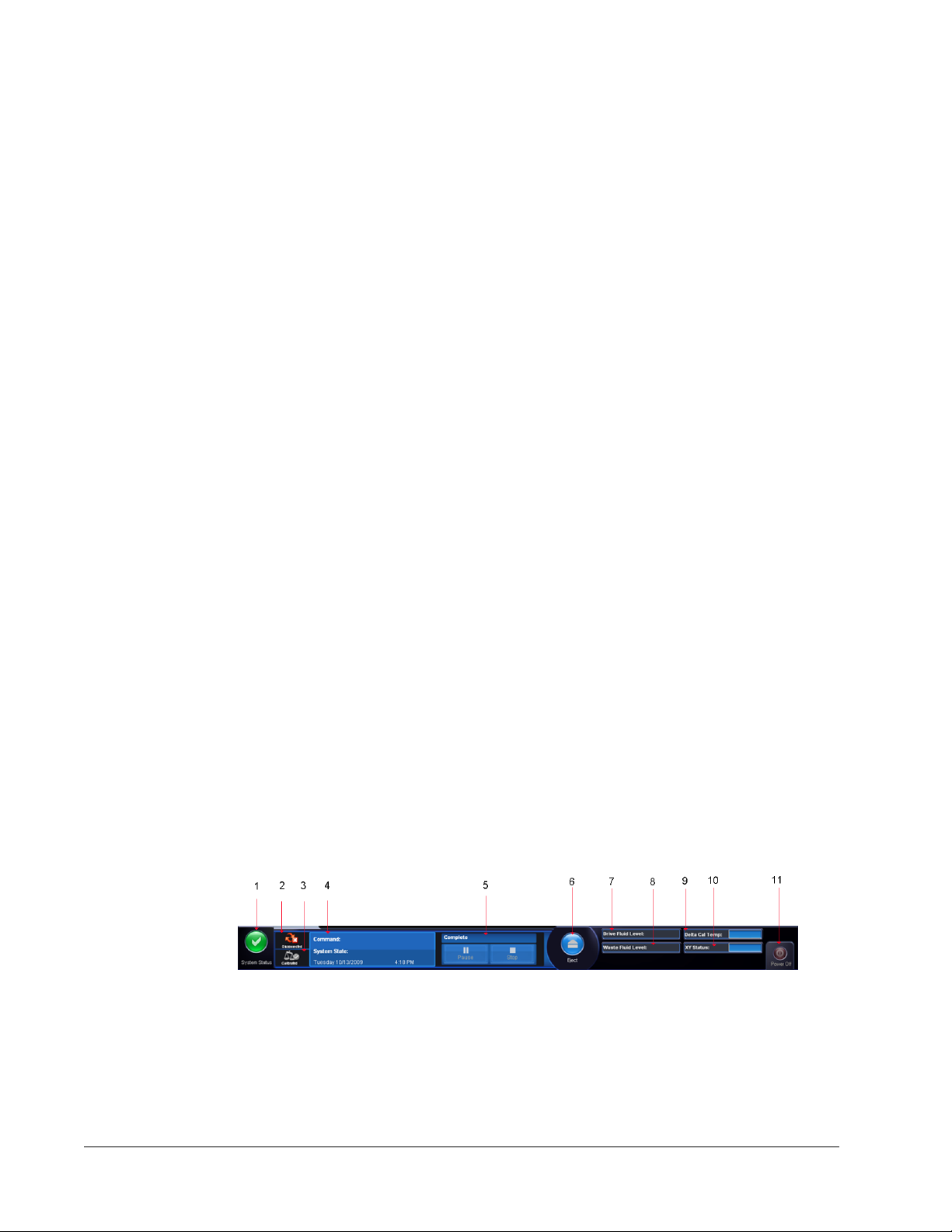
System Monitor
The System Monitor is displayed at the bottom of all xPONENT windows. It displays the
physical state of the Luminex system. Values are reported directly from the Luminex system.
1. System Status Button 2. Connection Status
3. Check Cal/Ver Status 4.Command Display
5. Progress bar, Stop button, Pause button 6. Eject Button for plate carrier
7. Drive Fluid Level 8. Waste Fluid Level
xPONENT for MAGPIX 4.2 Software User Manual
4
Page 18

9. Delta Cal Temperature 10. XY Status
11. Power Off button
System Status Button - This button has two functions: When clicked, it opens the system
log. It also displays the current status of the system. If there are no warnings or errors, the
System Status button is green with a check mark. If there is a warning, out of calibration
condition, or other important user notification, the button is yellow with an exclamation point.
Connection Status - Displays the status of the analyzer’s connection to the PC (Connected
or Disconnected). To ensure the analyzer connects to the PC, turn on the analyzer before
you start xPONENT.
Check Cal/Ver - If this displays a white X, there is a failed calibration or verification. Click the
scales to open the System Information tab to see details about the last calibration and other
important instrument information.
Command Display - Displays the following:
• The command currently running.
• The system state (i.e. running, idle, etc.).
• Date and time.
Progress - Displays a bar graph showing the progress of the current command or routine; if
the command or routine is finished, it displays a full progress bar and the command status as
Complete.
Pause - Pauses the system after the current command completes. Pause does not stop the
system in the middle of running a command. You cannot run another command while the
system is paused. Pause the system before stopping it so that it will finish the current
command and store the pending batch and then resume exactly where it left off.
Stop - Stops the system, regardless of command status. Use this only if it does not matter
whether the data from the current well is lost.
Help
Eject - Ejects the plate. Once the plate is ejected, the Eject button changes to Retract.
Retract retracts the plate, and the Retract button changes back to Eject.
Temp - Displays the difference in temperature between the current reading and the reading
when the system was calibrated, in degrees Celsius. If the temperature is out of tolerance,
this shows a high or low arrow. When clicked, it opens the Auto Maint tab.
XY Status - Displays the current location of the command, and the temperature of the plate
heating block in degrees Celsius. When clicked, it opens the Probe & Heater tab.
Drive Fluid Level - The Drive Fluid liquid level sensor warns you when the Drive Fluid is low.
There can be enough Drive Fluid left in the container to finish a plate. The system does NOT
stop until a air bubble is detected in the line coming from the Drive Fluid container.
Waste Fluid Level - The waste fluid container liquid level sensor stops the current plate if the
waste container is full.
To display online help for the tab in which you are currently working, click the blue “i” icon at
the upper right of the xPONENT window. This opens a help window with information specific
to that tab.
To display system-level help, click the blue question mark at the top of the xPONENT
window, then click Contents and Index. The online help opens and you can navigate to any
available topic.
Introduction
5
Page 19
To display quick start information, click the blue question mark at the top of the xPONENT
window, then click Quick Start. This displays information about the seven basic steps to start
the system.
Quick Start
The five steps to starting and using xPONENT are the following:
To Go to Expanded Help
Adjust the sample probe height Home > Probe and Heater Adjusting the Sample Probe
Initialize the system Home > System Initialization Running the System Initialization
Routine
Run an assay Home > Create a new Batch
Analyze Results > Saved Batches Performing Analysis
Print reports Results > Reports Reports Tab
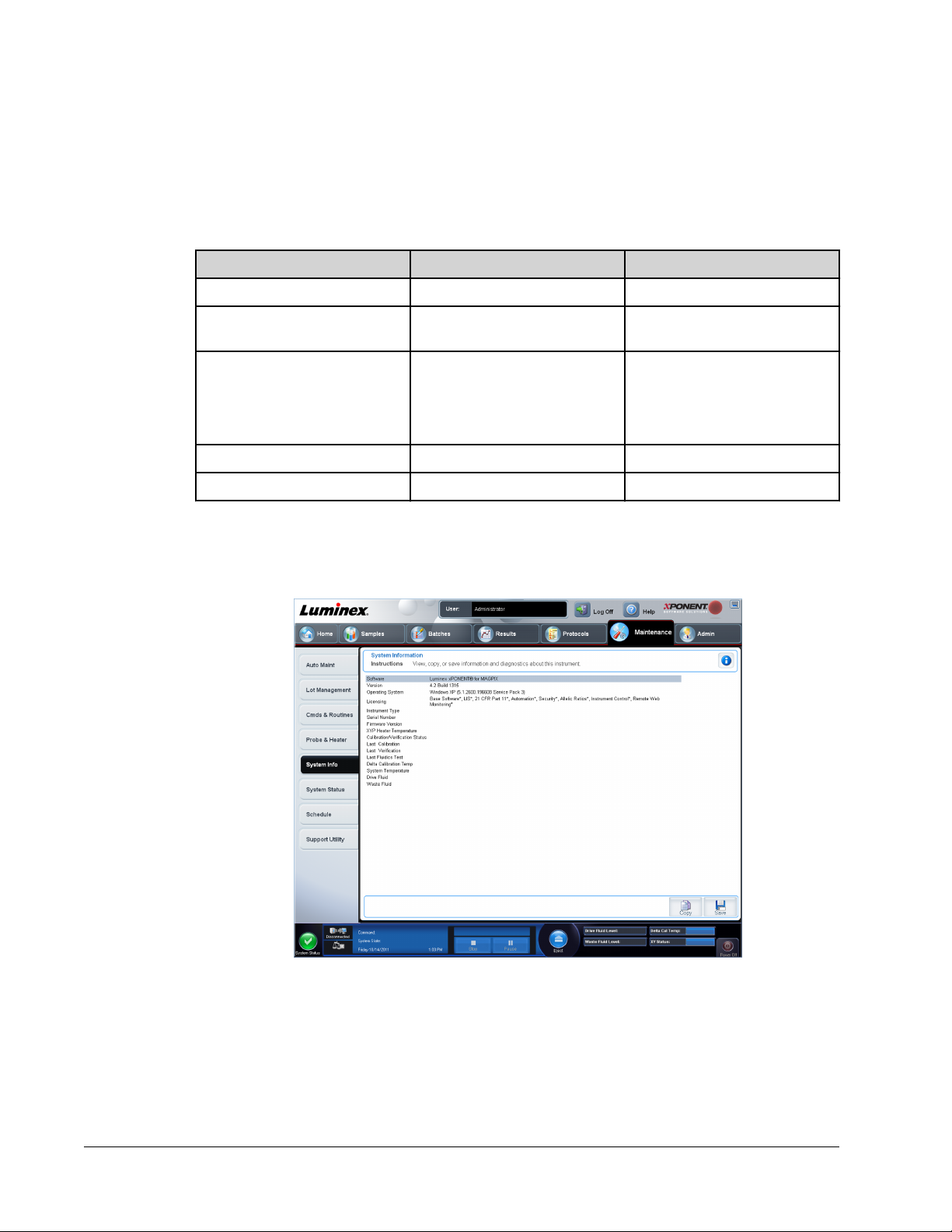
System Info Tab
Maintenance > System Info
from a new protocol, or Home
> Create a new Batch using
the highlighted protocol below
Create a New Batch from a New
Protocol
Create a New Batch from an
Existing Protocol
Use this tab to view information and diagnostics about the Luminex instrument.
This tab contains the following information:
• Software
• Version
• Operating System
• Licensing
xPONENT for MAGPIX 4.2 Software User Manual
6
Page 20

• Instrument Type
• Serial Number
• Firmware Version
• XYP Heater Temp
• Calibration/Verification Status
• Delta Calibration Temp
• System Temperature
• Last CAL Calibration
• Last VER Verification
• Last Fluidics Test
• Drive Fluid
• Waste Fluid
Items in this list relating to calibration and verification have one of the following states:
• Passed - Indicates that the process completed successfully.
• Failed - Indicates that the process was not completed successfully. Failed items appear in
red.
• Not Current - Indicates that verifiers are not current. Verifiers are not current if you have
not calibrated the system since the last time you ran the verifiers.
• Not Yet Run - Indicates that this process has not yet been run on the machine.
Copy - Copies the system information to the Windows clipboard. You can then paste it into a
text editor such as Notepad.
Save - Opens the Save As dialog box to specify a file name and location to save the system
information file.
Basic Procedures
Starting xPONENT
Perform the following steps to launch xPONENT:
• On the PC desktop, click the Luminex xPONENT icon, or click Start > All Programs >
Luminex > xPONENT > Luminex xPONENT.
• If you have a trial license, contact Luminex Technical Support to obtain a full license, or
click OK in the dialog box to continue.
• If this is the first time you have started the software, the User License Agreement may
display. Read the license agreement. Select I accept the terms of this license
agreement, then click OK.
NOTE: For safety and legal information, refer to the MAGPIX Installation and
Hardware User Manual that you received with your instrument.
Introduction
7
Page 21

Adding a New License Key
Contact Luminex Technical Support if you have any difficulty saving or adding a new license
key.
1. Access the Admin page, then the Licensing tab.
2. Click License (bottom right corner of window).
3. Copy and paste the new key into the License Code field. The License File field remains
blank.
4. Click OK. This closes xPONENT, applies the license, and restarts xPONENT.
Logging On to xPONENT
If your version of xPONENT is licensed for 21 CFR Part 11, Security, or both, an application
administrator must set up user IDs (and passwords, if required). If you are not using a version
with 21 CFR Part 11, the security module, or both, users can log in with any username or with
no username.
NOTE: Contact Luminex Technical Support if you have problems logging on.
If you want to purchase a license for 21 CFR Part 11 or the security
module, contact Luminex to place an order.
xPONENT for MAGPIX 4.2 Software User Manual
8
Page 22
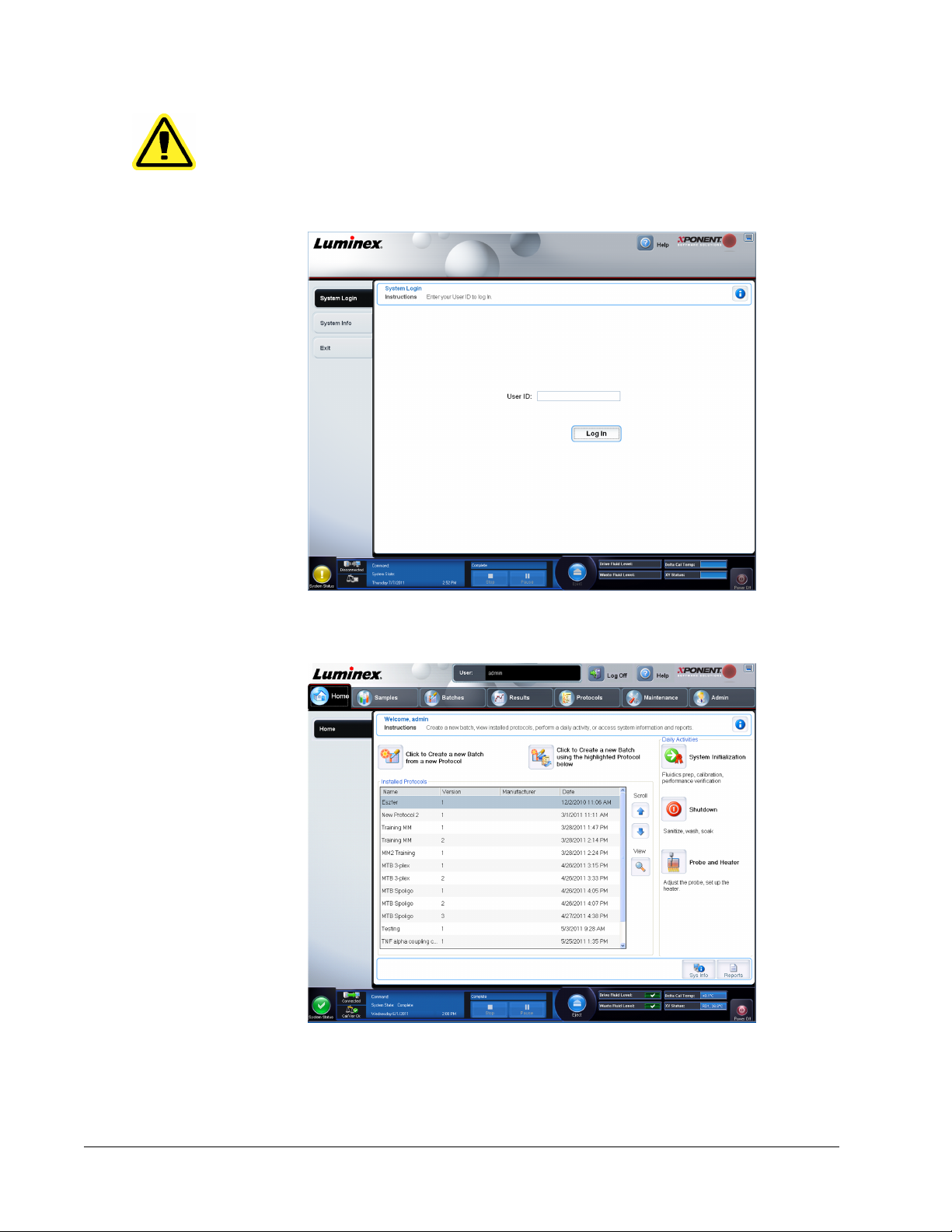
CAUTION: Use of this software by untrained personnel can result in
inaccurate data and test results. Users of xPONENT must read
the documentation thoroughly before operating the software.
1. On the System Login tab, type your user ID.
2. If you are using a secure version of the software, type your password. The Home page
opens.
Initial Startup
When you turn on the system for the first time, perform the following procedures:
Introduction
9
Page 23

1. Adjusting the Sample Probe Height
2. Revive After Storage (Luminex) Routine
3. Calibration/Verification
Adjusting the Sample Probe Height
Adjust the sample probe height to ensure that the probe drops far enough into the well to
acquire sample.
NOTE: Ensure that there is no liquid in the wells or reservoirs before
adjusting the sample probe height.
1. On the Home page, click Probe and Heater under Daily Activities. The Probe &
Heater tab opens.
2. Use well D6 (this is the center of a standard 96-well plate).
3. Ensure that the well location is selected on the plate image. A green pin marks the
selected well.
4. Based on the type of plate you are using, place alignment disks or an alignment sphere in
the well.
• For a standard 96-well plate - none
• For a Filter-bottom plate - two 5.08 mm disks
• For a Mylar-bottom plate - two 5.08 mm disks
• For a conical (v-shaped) plate - one sphere
5. Click Eject to eject the plate carrier.
6. Place the off plate reagent block on the plate carrier. Make sure it is well seated so that it
clips into place.
7. Place a strip well (provided with the Calibration and the Performance Verification kit) in
the off-plate reagent block.
8. In the Strip Wells section, click SD1.
9. Verify that the reservoir is empty.
10. In the Reservoir section, click well RB1.
11. Verify that the plate is not warped. Warped plates can lead to incorrect probe height
adjustment.
12. Place the plate on the plate carrier with well A1 positioned as indicated on the plate
carrier.
13. Click Retract to retract the plate carrier.
14. Type a name for the plate in the Plate Name box.
15. Click Auto Adjust Height. The probe automatically adjusts itself to the locations you
selected.
NOTE: The probe height is automatically set to 0.98 mm. The probe
automatically adjusts this distance from the bottom of the plate, or
calibration disks or spheres.
16. Click Eject to eject the plate holder. If you used alignment disks or spheres, remove them
from the plate.
xPONENT for MAGPIX 4.2 Software User Manual
10
Page 24

NOTE: When you adjust and save the probe height settings for all three
areas under a plate name, all areas retain the adjustment.
WARNING: Correct sample probe height is critical to successful sample
acquisition and calibration. Problems with the sample probe can
lead to fluid leaks and inhibit sample acquisition.
CAUTION: Ensure that the probe height is set correctly before calibrating
the system.
FIGURE 1.
Sample Probe Height Adjustment
Revive After Storage Routine
NOTE: The Revive After Storage routine is necessary when the system
runs for the first time and is recommended when the system has
been idle for more than a week.
After you have adjusted the sample probe height, run the Revive After Storage (Luminex)
routine.
1. Open the Maintenance page, then the Cmds & Routines tab.
2. Select Revive After Storage (Luminex) from the drop-down list. The Revive After
Storage routine performs the following commands:
• Prime
• Rinse
• Alcohol Flush
• Rinse
Introduction
11
Page 25
3. Add 70% isopropanol or ethanol to reservoir RB1 on the off-plate reagent block as
indicated on the Cmds & Routines tab.
NOTE: The rinse reservoir (RD1) should be empty.
4. Click Retract.
5. Click Run.
After the Revive After Storage routine is complete, run the System Initialization routine.
System Initialization
xPONENT for MAGPIX contains a pre-defined routine to prepare the analyzer for data
acquisition. This section describes calibration and performance verification of the system.
Calibrator magnetic beads are used to normalize the settings for the reporter channel and
classification channels. Verification magnetic beads are used to verify calibration and optical
integrity of the system. Fluidics beads are used to assess well-to-well carryover.
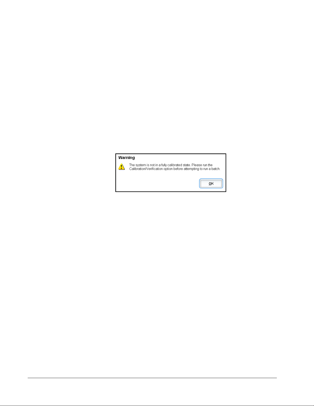
If the system is not fully calibrated, a warning message opens.
Once calibrated, the values remain until you recalibrate. You can track system calibration and
verification results through the Calibration and Verification report. Target value information
for calibration and verification beads is available on the Luminex website at http://
www.luminexcorp.com/Support/index.htm.
Calibrate your system at least once a week using the Calibration/Verification button on the
Auto Maint tab of the Maintenance page. In addition, recalibrate the system if any of the
following things occur:
• The delta calibration temperature exceeds ± 5° C.
• You move the instrument.
• You experience sample acquisition problems.
• The instrument undergoes hardware maintenance, such as replacement of a part.
Verify the system daily using the Performance Verification button on the Auto Maint tab of
the Maintenance page. Refer to your assay kit instructions for additional calibration
frequency requirements.
Before you can calibrate the system, you must import MAGPIX calibrator and verification
bead lot information. Do this using the Lot Management tab of the Maintenance page. This
information is available on the CD that accompanies the Performance Verification Kit and
Calibration Kit, and is also available on the Luminex website at http://www.luminexcorp.com/
Support/index.htm.
xPONENT for MAGPIX 4.2 Software User Manual
12
Page 26

Running the System Initialization Routine
1. On the Home page, click System Initialization under Daily Activities. The Auto Maint
tab opens. On the Auto Maint tab, the System Initialization option is automatically
selected.
2. Verify that the correct lot kit is displayed in the Calibration and Performance
Verification drop down field and that the correct reagents (for example, VER and
Fluidics reagents) have been added to the off-plate reagent block.
3. Fill reservoir RB1 3/4 full of 70% isopropanol or ethanol.
4. Verify that the Rinse reservoir RD1 is empty.
5. Click Retract.
6. Click Run.
Daily Activities
System Initialization - Perform a system initialization routine.
NOTE: Luminex recommends weekly calibration and daily verification. For
Shutdown - Perform the shutdown routine.
Probe and Heater - Adjust the probe height or plate heater.
Drive Fluid Lot - Enter the Drive Fluid lot number, which is printed on the box in which the
fluid container was shipped. This information is optional.
Create a New Batch from a new Protocol - Creates a new batch from a new protocol by
opening the Settings tab of the Batches page. You can create protocols while creating a
batch, and can save the protocol before or after you run the batch.
Create a New Batch from the highlighted Protocol below - Creates a new batch using a
selected protocol from the Installed Protocols list. This button displays the same fields as
the Create a new batch from existing Protocol button on the Batches page.
Scroll - Use the up and down arrows to scroll through the list of installed protocols.
View - Opens the Settings tab of the Protocols page to view the selected protocol. This tab
enables viewing the settings, analytes, and plate layout for the selected protocol.
Sys Info - Opens the System Info tab of the Maintenance page. If the instrument is
connected and powered on, the System Information page displays licensing information, the
instrument serial number, the date of the last Calibration, Verification, Fluidics tests, and
other important information.
Reports - Opens the Reports tab of the Results page.
daily use, verify your System Initialization setting is set to Fluidics
Prep and Performance Verification in the Admin System Setup tab.
Refer to Maintenance Page for detailed maintenance instructions.
Return to the Home page at any time by clicking Home at the top of the screen.
Shutting Down the Analyzer
Run the daily shutdown routine to prevent clogs and crystallization of salt in the sample
probe. Clogs and crystallization of salt in the sample probe can cause problems with
calibration, verification, and data acquistion; they can also cause sample splashing. Shut
down the system properly to ensure system integrity.
Introduction
13
Page 27

1. On the Home page, click Shutdown. The Auto Maint tab opens, with System
Shutdown selected.
2. Click Eject.
3. Fill reservoir RA1 with 3/4 of DI water.
4. Fill reservoir RC1 with 3/4 of 10%-20% household bleach solution.
5. Verify that reservoir RD1 is empty.
6. Click Retract.
7. Click Run.
Logging Off and Exiting
To log off and exit xPONENT:
1. Click Logoff at the top of the page.
2. When the Confirm dialog box opens, click OK. This opens the Log In page, with Exit on
the left tab.
3. Click Exit to exit the application.
Using Online Help
English-language help is available at all times while you are using xPONENT. To display
online help for the page or tab in which you are currently working, click the blue “i” icon at the
upper-right of the xPONENT window. This opens a help window with information specific to
that page or tab.
xPONENT for MAGPIX 4.2 Software User Manual
14
Page 28

To display system-level help, click the blue question mark at the top of the xPONENT
window, then click Contents and Index. The online help opens, where you can navigate to
any available topic.
To display quick start information, click the blue question mark at the top of the xPONENT
window, then click Quick Start. This displays information about the basic steps to start the
system.
To display software information, click the blue question mark at the top of the xPONENT
window, then click About Luminex xPONENT. The xPONENT information dialog box opens,
displaying the software version information.
Luminex Support
Luminex Website
Additional information is available on the Luminex website. FAQs are available at http://
www.luminexcorp.com/Support/index.htm.
You can access the Technical Support Website using a user name and password at https://
oraweb.luminexcorp.com/OA_HTML/jtflogin.jsp.
Contacting Technical Support
Luminex Technical Support representatives are ready to help you. If the question or problem
relates to materials from the assay kit, contact the kit provider directly.
Luminex Technical Support is available to users in the U.S. and Canada by calling
1-877-785-BEAD (2323). Users outside of the U.S. and Canada can contact us at +1
512-381-4397. Inquiries may also be sent by email to support@luminexcorp.com.
Software Packages
Multiple levels of user access can be licensed for xPONENT.
Basic - Allows instrument control.
Additional features for which you can obtain a license:
• Secure - Includes all of the Basic functions as well as administrator-controlled user
permission levels.
• 21 CFR Part 11 - Includes all of the Secure package features as well as the option to
require electronic signatures to perform certain tasks. (Electronic signatures are listed in
the system log.)
• Automation - Includes the ability to communicate with external hardware.
• Allele - Enables you to use allelic ratios.
Introduction
15
Page 29

• Remote Web Monitoring - Enables you to view alerts and system status using a
webpage.
• LIS - Enables the system to communicate with an external Laboratory Information System
(LIS) database. The LIS package enables you to export and import patient result data in
ASTM file format.
You must have an instrument control license to operate the instrument.
For more information about purchasing upgraded packages, or to obtain specific package
documentation, contact your vendor.
MAGPIX Technology
The MAGPIX system operates by using magnetic beads (microspheres) that are coated with
a reagent specific to a particular bioassay, enabling the capture and detection of specific
analytes from a sample. The sample mixture is aspirated by the sample probe and conveyed
via Drive Fluid into the camera chamber, where the beads are pulled down into a monolayer
by the magnet, immobilized, and imaged. Within the chamber, beads are exposed to a red
LED and a green LED, which excite both the internal dyes that identify each bead’s color
signature and the reporter fluorescence from the surface of the beads. The red LED is
responsible for classifying the beads. The CL1 and CL2 filters function to categorize the
beads based on color signature and place them properly on the bead map as well as throw
out any doublets that may exist. The green LED with the RP1 filter excites the reporter
fluorescence, which identifies the quantity of analyte captured for each bead region. The
beads are then flushed to the waste container, clearing room for the next sample.
Calibration is important to ensure that the optical system functions effectively and that
different Luminex MAGPIX systems report similar results. Calibrating the MAGPIX system
normalizes the settings for the classification channels (CL1 and CL2) and the reporter
channel (RP1). Use the Luminex MAGPIX Calibration Kit to accomplish this.
Following calibration, use the Luminex MAGPIX Performance Verification Kit to check all of
the optical channels in the system for correct calibration. It is essential to verify every time
you calibrate. If there is a problem with optical integrity or fluidics, MAGPIX may pass
calibration but fail performance verification. The Luminex MAGPIX Performance Verification
Kit includes reagents to verify the calibration and optical integrity for the Luminex MAGPIX
system as well as reagents to verify the fluidics channels using observations of bead count
and well-to-well carryover.
xPONENT for MAGPIX 4.2 Software User Manual
16
Page 30
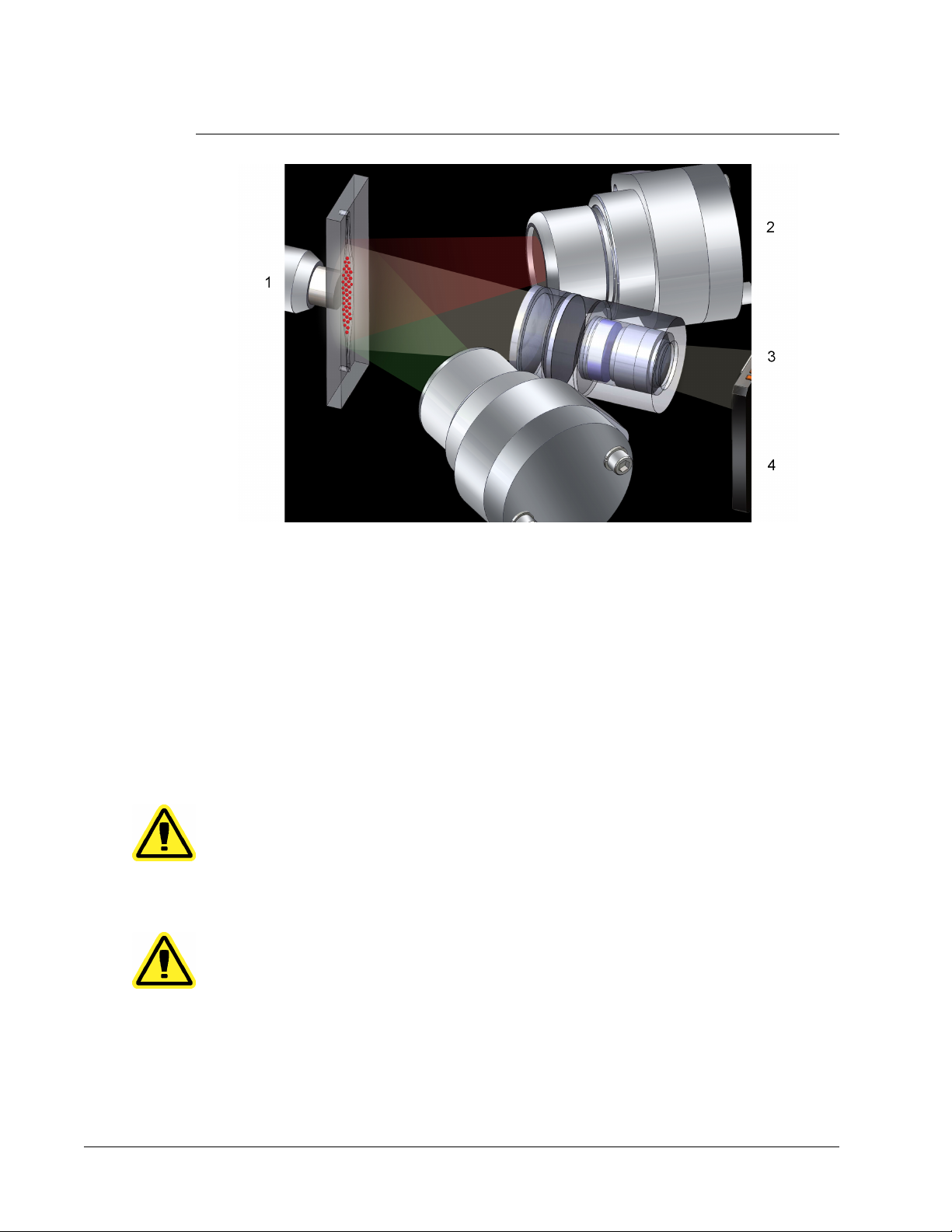
FIGURE 2.
LED Image-Based Analysis
1 Beads in chamber
2 Red LED (635 nm)
3 CCD Imager
4 Green LED (525 nm)
Running Assays with MAGPIX
General Guidelines
WARNING: Modifying or deleting xPONENT system files can cause
degradation of system performance. Repair modified or deleted
xPONENT system files by uninstalling and re-installing the
xPONENT software. Luminex recommends that you contact
Luminex Technical Support before uninstalling and reinstalling
xPONENT.
WARNING: Using unauthorized third-party software with xPONENT
software can result in corruption or failure of the xPONENT
software. Use third-party software at your own risk. The
operation of the system software is validated only when it runs
alone on the dedicated PC.
NOTE: If you are using a screen saver on the PC on which xPONENT is
installed, xPONENT prevents it from activating. A dialog box opens
each time xPONENT is launched, recommending that the screen
saver and any power management settings be turned off.
Introduction
17
Page 31

CAUTION: This system contains electrical and mechanical components that,
if handled improperly, are potentially harmful. Adhere to standard
laboratory safety practices.
CAUTION: Protection provided by the equipment can be impaired or the
warranty voided if the Luminex system is used in a manner not
specified by Luminex documentation or Luminex Corporation.
Biological Samples
CAUTION: Human and animal samples may contain biohazardous
infectious agents. Where exposure to potentially biohazardous
material—including aerosol—exists, follow appropriate biosafety
procedures and use personal protective equipment such as
gloves, gowns, laboratory coats, face shields, or mask and eye
protection. Use ventilation devices. Observe all local, state, and
federal biohazard handling regulations when disposing of
biohazardous waste material.
Dilute concentrated biological samples, such as plasma or serum, at least 1:5 with reagents
as part of assay setup or as a final dilution step to reduce the chance of system clogs. If you
are running a MagPlex® kit, follow the dilution instructions in the kit’s product insert.
Bead (Microsphere) Handling
MagPlex beads come in various configurations. To reduce foaming and precipitation, avoid
agitating the beads until you are ready to vortex and use them. Beads settle and must be
resuspended by vortexing before use. In addition:
• Multiple pipetting from the original container can affect bead concentrations.
• Protect MagPlex beads from light at all times to prevent photobleaching. Photobleaching
effects are cumulative. To maintain the integrity of the beads, minimize their exposure to
light during your development and manufacturing phases.
• Store MagPlex beads at 2°- 8°C.
NOTE: Refer to the product information sheet that accompanies your
MagPlex beads or for additional information.
Repetitive MagPlex Bead Measurements
In a MagPlex assay, the reporter signal is the result of the assay. Due to small bead size,
MagPlex bead suspension exhibits near solution-phase reaction kinetics. This means that
each set of beads used for a particular assay shows a statistically even distribution of
reporter molecules bound to the surface of each bead. The fluorescence signal of reporter
molecules bound to the surface of each bead set is measured and used to determine the
result of each assay in a multiplex. During data acquisition, numerous beads of each set are
analyzed and the median statistic is computed for that set by xPONENT. The more beads of
a set measured, the more confidence that can be given for that particular measurement.
Luminex recommends that you use R-Phycoerythrin as your reporter fluorophore.
If you are running a calibration and verification kit, follow the kit's product insert or use the
software protocol provided.
xPONENT for MAGPIX 4.2 Software User Manual
18
Page 32

Classification and Reporter Fluorochromes
MagPix beads in the calibration kit are used to autofocus the camera and calibrate the CL1,
CL2, and RP1 channels. The beads in the verification kit are a mix of 6 different regions that
cover the range of the 50-plex map. Both calibration and verification beads are triple-dyed,
and the fluorescence signal of these dyes enables classification of each bead set.
TABLE 1.
Region Region Region
MC10012 MC10013 MC10014
MC10015 MC10018 MC10019
MC10020 MC10021 MC10022
MC10025 MC10026 MC10027
MC10028 MC10029 MC10030
MC10033 MC10034 MC10035
MC10036 MC10037 MC10038
MC10039 MC10042 MC10043
MC10044 MC10045 MC10046
MC10047 MC10048 MC10051
MC10052 MC10053 MC10054
MC10055 MC10056 MC10057
MC10061 MC10062 MC10063
MC10064 MC10065 MC10066
MAGPIX Active Bead Regions (by Region)
MC10067 MC10072 MC10073
MC10074 MC10075 MC10076
MC10077 MC10078
Fluidics 1 and Fluidics 2
Although it undergoes a wash step in between wells, the probe can be susceptible to carryover from well-to-well. Fluidics 1 contains one bead set. Fluidics 2 contains a buffer solution
and a different control bead. The function of this maintenance procedure is to measure how
much (as a percentage) of the first bead set in Fluidics 1 is found in the well where Fluidics 2
has been loaded.
Sample Volume
Sample volumes range in size from 20 µL to 200 µL. Ensure that approximately 25 µL more
than the sample volume remains in the well after aspiration. This amount may vary
depending on the type of plate used. Your sample volume must be large enough to prevent
aspirating air into the fluid line when acquiring sample, and small enough to prevent spill-over
Introduction
19
Page 33

when the analyzer flushes the sample lines after sample acquisition and expels
approximately 75 µL of sample back into the well.
Examples
• If you use a sample volume of 50 µL and aspirate 50 µL, you acquire air bubbles.
• If you use a sample volume of 200 µL and a standard sample pickup of 50 µL, the well
overflows when the analyzer washes the sample lines after acquisition and expels fluid
back into the well, because the amount of fluid expelled back into the well is approximately
75 µL.
CAUTION: Sample volume is critical to the proper functioning of your
MAGPIX instrument. Aspirating too few beads can result in
insufficient bead count or insignificant data results. Aspirating too
many beads can result in saturation of the chamber and prevent
proper bead classification, which may also result in low bead
counts or inconclusive data.
This formula quantifies the volume restrictions on the assay design:
Total well volume (µL) - Sample uptake volume (µL) + 75 (µL) <Maximum Well Volume (µL)
Where:
• Total well volume = Starting sample volume before the instrument acquires sample.
Sample volume is determined by the consistency of the bead set.
• Sample uptake volume = Uptake volume for acquisition (program this in the protocol as
sample volume).
• 75 (μL) = Volume expelled back into the well.
• Maximum well volume = The maximum volume capacity of the wells in a selected 96-well
microtiter plate.
You can change the sample size while running a batch using the Change Volume button on
the Current Run tab.
If you are running a MagPlex kit, follow the kit’s product insert or use the software protocol
provided.
Do not dilute MagPix Calibration or Verification beads, or the Fluidics 1 and Fluidics 2 beads.
Plates
Follow these guidelines when choosing plates:
• When using uncovered plates, use black opaque plates to reduce photobleaching.
• For heated assays, use CoStar® Thermowell® 96-well, thin-wall polycarbonate, model P
• For unheated assays, use a 96-well plate with an overall height no greater than 0.75
plates.
inches (19 mm).
CAUTION: The heater block or plate can be hot and can cause personal
injury when touched. Use care when you are working with it and
do not touch it.
xPONENT for MAGPIX 4.2 Software User Manual
20
Page 34

See the recommended consumables list on the Luminex website at http://
www.luminexcorp.com/Support/index.htm and click Recommended Materials from the
Support Resources section for more information.
Introduction
21
Page 35

xPONENT for MAGPIX 4.2 Software User Manual
22
Page 36

Chapter 2: Samples Page
Samples Page Functionality
Samples > Samples
Use this tab for the following:
• Click Create New Samples to display the Create Samples subtab, on which you can
create a new sample.
• View sample lists, including a list of protocols with version number and the number of
samples associated with each protocol.
23
Page 37

• Click Details to display the Edit Samples subtab, on which you can view or edit sample
details for the selected protocol.
• Click Create Batch to name the LIS batch for a protocol. This opens the Batches page,
Batches tab, with the following subtabs displayed:
• Protocol
• Stds & Ctrls
• Plate Layout
Edit Samples and Create Sample Subtab
Samples > Samples > Edit Samples or Create Sample
Click Create Samples on the Samples tab to display this subtab. Use this subtab to type and
view sample information.
This tab contains the following:
Protocol - Displays the protocol selected in the Samples tab. If xPONENT has a LIS license
enabled, any sample details provided by the LIS also appear in the Sample list.
Version - Displays the protocol version number. This cannot be edited.
NOTE: If a protocol is created using the same name and version as a
previously deleted protocol, previous or pending samples are relinked to the added protocol.
Sample - If you have the LIS-enabled version of the software and are currently connected to
the LIS, the sample list autopopulates when the LIS provides samples orders. You can only
view or run a sample list created in the LIS; you cannot edit it. Use Create New Samples to
create a new sample. After you have typed and saved the sample information, it appears in
the list to the left. This list displays the samples you have already created. To reorder the
sample’s acquisition location, use the move arrows.
xPONENT for MAGPIX 4.2 Software User Manual
24
Page 38

The following Delete, New, Edit, and Undo buttons only display depending on actions taken
in the Create Sample tab.
Delete - Deletes a highlighted sample.
New - Creates a new sample.
Edit - Edits a highlighted sample.
Undo - Reopens the Create Sample tab without saving any changes made using the Edit or
New buttons.
Save - Saves changes made to the Sample list.
Close - Returns to the Samples tab.
Creating a New Sample List
Follow these steps to create a new sample list.
Samples Page
25
Page 39

1. Open the Samples page.
2. In the Sample Lists section, select the protocol you are using for the sample list, then
click Create New Samples. The Create Sample tab opens.
3. In the ID box, type the sample ID.
4. Type a patient first name in the First name box (optional).
5. Type a patient last name in the Last name box (optional).
6. To add a comment about the sample, type it in the Comment box; this is optional.
7. Click Save to add the sample to the Sample list.
xPONENT for MAGPIX 4.2 Software User Manual
26
Page 40

8. To add more samples, click New. Repeat Steps 3-7 until you have added all of the
samples you want in your samples list.
9. Once you have added all the desired samples, click Close.
NOTE: Samples can also be added using an LIS.
Editing a Sample List
1. Open the Samples page.
2. In the Samples list section, choose the protocol you want to edit, then click Details. The
Edit Samples subtab opens.
Samples Page
27
Page 41

3. Click a sample, then use the Move arrows to move it up or down in the sample list,
changing the order in which they will be acquired.
4. To add a new sample to the list, click New, then perform the following steps:
a. In the ID box, type the sample ID.
b. Type a patient first name in the First name box (optional).
c. Type a patient last name in the Last name box (optional).
d. To add a comment about the sample, type it in the Comment box; this is optional.
e. Click Save to add the sample to the Sample list.
5. To edit an existing sample, click the sample, then click Edit.
6. Once you have completed editing the sample list, click Close.
xPONENT for MAGPIX 4.2 Software User Manual
28
Page 42

Chapter 3: Batches Page
Batches Page Functionality
Batches > Batches
Options on the Batches tab on the Batches page are:
• Create a New Batch from an existing Protocol
• Create a New Batch from a new Protocol
• Create a New Multi-Batch
Depending on your selection, this page displays the following tabs:
• Protocols - Displays when Create a New Batch from an existing Protocol is clicked.
• Stds & Ctrls - Displays when Create a New Batch from an existing Protocol and
Create a New Batch from a new Protocol are clicked.
29
Page 43

• Analytes - Displays when Create a New Batch from a new Protocol is clicked.
• Plate Layout - Displays when Create a New Batch from an existing Protocol and
Create a New Batch from a new Protocol are clicked.
• New MultiBatch - Displays when Create a New Multi-Batch is clicked.
NOTE: These tabs (except New MultiBatch) are sequential. You must
complete each screen in a specific order.
The Pending Batches list displays the name of the protocol used with the batch, the protocol
version, date, and status for each pending batch. The following buttons only appear if the
pending batches have data:
• Single Step - Instructs the system to acquire one well and then pause. If Single Step is
activated during a batch, the batch pauses at the end of the current well. This ensures that
the system is working correctly before you run an entire batch.
• Save Prtcl. - Saves protocol and/or assay information for a standard/control.
• Plate Layout - Opens the Report dialog box, which includes the Batch Plate Layout
Report.
• Import - Imports a batch not previously run in xPONENT 4.2 from a folder on the PC into
xPONENT.
• Export - Exports the batch information in order to move it to another computer, make a
copy of the data, and then import it into xPONENT on another computer.
• Delete - Deletes a batch.
• Edit - Edits a batch.
• Run - Runs a batch.
Setting Up Batches
Batches consist of protocols and samples for acquisition and can span more than one plate.
Protocols contain predefined commands that must be included in every batch acquisition.
You can group batches together as a multi-batch. Multi-batches can consist of any number of
batches that have been set up from different protocols and are processed consecutively.
Multi-batches cannot be run on multiple plates.
NOTE: When setting up a batch, if the number of samples exceeds the
number of wells in one microtiter plate, you can add additional plates
in the Add and Change Plate secondary window. Additional plates
are identified on the bottom of the plate image as Plate a of b, where
a is the plate number and b is the total number of plates.
Assay kit manufacturers may provide protocols in their kits which are distributed on a CD.
Protocols typically include assay standards, controls, and maintenance commands (such as
washes or primes to acquire along with samples). Assay reagents are included in assay kits.
You must provide information about these reagents, such as lot numbers and concentration
values for the standards and assay controls.
Using the Batches Page
xPONENT for MAGPIX 4.2 Software User Manual
30
Page 44

1. Open the Batches page.
2. Click one of the following:
• Create a New Batch from an Existing Protocol
• Create a New Batch from a new Protocol - if you select this option, you can save the
prootocol and/or stds/ctrls information.
• Create a New Multi-Batch
3. Type the batch name in the Batch Name box.
4. Type an optional description of the batch in the Enter Optional Description box.
5. If you are creating a batch from an existing protocol, select the protocol in the list. Click
Next. If the protocol uses standards and/or controls, the Stds & Ctrls tab displays.
6. If you selected Create a New Batch from a new Protocol, the Stds & Ctrls tab
displays.
7. The Plate Layout tab appears. View the details of the active reagents, apply different
assay standards/controls, or manually enter new information. Click Next.
8. On the Plate Layout tab, assign well commands for this batch.
9. Click Run Batch to begin batch acquisition, or click Save to save batch information to the
Pending Batch list to be run at a later time.
NOTE: If the batch spans more than one plate, the tray ejects automatically
when all defined wells have been acquired. A dialog box displays
prompting you to insert the next plate.
Create a New Batch from an existing Protocol
Read the instructions provided with the assay kit you are using.
1. Open the Batches page.
2. Click Create a New Batch from an existing Protocol.
3. Type the batch name in the Batch Name box.
4. Type a description about the batch in the Enter Optional Description box.
5. Click a protocol you wish to use in the Select a Protocol list.
6. Click Next. If the protocol uses standards, controls, or both, the next tab that opens is the
Stds & Ctrls tab. View the details of the active reagents or apply different assay
standards, controls, or both or manually enter new information. Select Next. If the
selected protocol does not use standards, controls, or both, the next tab that opens is the
Plate Layout tab.
7. On the Plate Layout tab, assign well commands for this batch. See Plate Layout Tab for
a complete description of the commands and options on this tab.
8. Click Run Batch to begin batch acquisition, or click Save to save batch information to the
Pending Batch list to be run at a later time.
NOTE: If the batch spans more than one plate, the tray ejects automatically
when all defined wells have been acquired. A dialog box opens,
prompting you to insert the next plate.
Protocol Subtab
Batches > Batches > Protocol
Batches Page
31
Page 45

Use this tab to name a batch, type a batch description, select a protocol, and view active
reagents. This tab contains the following:
• Batch Name/Description - Used to name and describe a batch.
• Select a Protocol - Contains the protocol name, version, manufacturer, and creation date
for each protocol.
• Active Reagents - Displays assay and control lots/kits associated with the selected
protocol. The Standard/Ctrls Kit Name - Lot# field displays the assay standard/control kit/
lot name and lot number currently associated with the selected protocol. The Standard
Lots and Controls Lots fields display any standard or control lots associated with the
selected protocol.
• Cancel - Returns to the main Batches tab.
• Next - If you have selected a protocol with no standards or controls (displayed as None in
the Active Reagents section), clicking Next continues to the Plate Layout tab. If you have
selected a protocol with standards and controls, clicking Next continues to the Stds &
Ctrls tab.
Standards and Controls (Stds & Ctrls) Subtab
Batches > Batches > Stds & Ctrls
xPONENT for MAGPIX 4.2 Software User Manual
32
Page 46

Use this tab to apply a kit or lot to the batch. This tab contains the following:
Batches Page
33
Page 47

• Apply Std/Ctrl Kit - Opens the Select Std/Ctrl Kit dialog box. The dialog box displays the
Std/Ctrl Kit Lot #, Std/Ctrl Kit Name, Expiration, and Manufacturer for the kit. Select a
Std/Ctrl kit from the list and then click OK to close the dialog box. The kit information will
display in the boxes to the right of the Apply Std/Ctrl Kit button. The selected kit must be
associated with the same analyte names. You can also type information by clicking in the
Name, Std/Ctrl Kit Lot #, Expiration, and Manufacturer boxes and typing the
information.
• Assay Standard Information - Displays the selected standard reagents in a list. The list
displays the Reagent, Name, Lot #, Expiration, Manufacturer, and expected
concentration value of each analyte.
NOTE: Click a Reagent column header to re-sort the order from the highest
number standard to standard number one. This is useful for applying
dilutions in which the last standard is the highest standard.
• Apply Std Lot - Opens the Select Lot dialog box.
Select a lot from the list and then click OK to apply the lot.
• Apply Values - Applies a value across or down the Reagent, Name, Lot #, Expiration,
and Analyte fields. Type a value in these fields by double-clicking on them, and then
using one of the two Apply Values arrows to apply that value down or across the list of
analytes.
• Dilution - Contains the following dilution options:
• 1:2 - Halves the standard from each previous iteration.
• 1:10 (Log) - Computes a value of one-tenth of the standard from each previous
iteration.
• 1/2 Log - Creates a 1:3.16 dilution, or half of each 1:10 (Log) from each previous
iteration.
• Apply Dilution - Applies the dilution selected in the Dilution list.
NOTE: The Dilution List and Apply Dilution button are displayed only if a
quantitative analysis has been selected.
NOTE: You can also type a number to set your own dilution factor. It must
be a whole number.
xPONENT for MAGPIX 4.2 Software User Manual
34
Page 48

• Assay Control Information - Lists the selected control reagents. The list displays the
Reagent, Name, Lot Number, Expiration, and Manufacturer. Existing control lot
information can be applied or new information can be typed manually.
• Apply Ctrl Lot - Opens the Select Lot dialog box. Select a lot from the list and then
click OK.
• Show Concentration - Expected, Low, and High set the expected, lowest, or highest
acceptable concentration of the analyte in the sample.
• Apply Values - Applies a value down or across the list of analytes.
• Cancel - Returns to the Batches tab.
• Back - Returns to the previous tab.
• Next - Continues to the Plate Layout tab.
Plate Layout Subtab
Batches > Batches > Plate Layout
Use this tab to define commands that apply to one or more wells. You can also define offplate and maintenance commands. This tab contains the following:
• Plate Image - This is a representation of the plate. Each well is displayed as a circle on the
grid. Well commands appear in the appropriate circles as you assign them to wells on the
plate.
• Command Sequence - Contains the command sequence for the active plate. The list
includes all active wells, the type of command (Unknown, Standard, Control, Background,
or assigned maintenance command), ID, and dilution factor. Double-click the ID field to
type an ID. Double-click the Dilution field to type a dilution factor.
NOTE: A command's ID and Dilution fields have a blue border around them
if they can be double-clicked to type information.
• Move Command - These arrows move a selected command up or down in the Command
Sequence list, changing the acquisition order.
Batches Page
35
Page 49

• Import List - Opens the Open dialog box to import an existing command sequence list.
• Replicate Count - Defines a quantity of replicate sets from one to nine.
NOTE: Replicate count selection must be made before adding a well
command.
• Grouping - Selects the sequence in which the replicates are laid out in plate wells.
NOTE: Grouping selection must be made before adding a well command.
The options are:
• 123123123. . . Lays out one of each replicate set at a time in numerical order.
• 111222333. . . Lays out all the replicates in a set before moving on to the next set in
numerical order.
You can assign the following well commands. Each command is associated with a color.
You can click and drag to highlight a series of wells, click a column or row header to
highlight the entire column or row, or click and highlight different wells and then click a
command below to assign that command to all the highlighted wells.
• Unknown (U): Yellow
• Background (B): Purple
• Control (C): Red
• Standard (S): Green
The Delete and Start at Well commands are also available to assign as well commands.
Delete removes the well command for the selected well. The Start at Well command enables
you to begin acquisition at a well other than A1.
NOTE: Before adding well commands, delete all standards from the plate
layout if any of the standards need to be rearranged. Delete all
controls from the plate layout if any of the controls need to be
rearranged.
NOTE: Wells and commands you assign to the protocol plate layout are
saved into the protocol settings and execute each time you use the
protocol to run a batch. Standards and controls associated with a
given protocol typically remain constant, while the number of
unknown wells often varies. You can assign a specific number of
unknown wells to the plate when setting up a batch.
Commands and Routines - Allows you to add and delete commands and routines, and to
create pre and post batch routines. Select a well and then select the appropriate command:
• Add
• Delete
• Pre Batch Routine
• Post Batch Routine
NOTE: If you select a routine you created, that routine must also exist on
any system to which you import this protocol. The system displays
an error when attempting to run a batch on a system where the
routine does not exist.
xPONENT for MAGPIX 4.2 Software User Manual
36
Page 50

Clicking either Pre Batch Routine or Post Batch Routine opens the Commands and
Routines dialog box, where you can select the command or routine you want before or after
running the batch. Clicking Add after selecting a well opens the same box for you to select a
command or routine for that well. Clicking Delete after selecting a well deletes any
commands or routines associated with that well.
• Plate - Specifies the plate to display in the plate image in the list. Add Plate adds a new
plate to the batch, and Delete Plate deletes the plate highlighted in the list.
• Direction - Specifies the direction to run the plate commands. Select either horizontally or
vertically. The selected direction also dictates how wells are added to the plate when
assigning multiple unknowns, standards, and controls at one time.
• Plate Navigation - Displays a smaller plate image for the current batch.
• Single Step - Instructs the system to acquire one well and then stop. Use this to ensure
the system is working correctly before you run the whole batch.
• Off Plate Area - Designates an alternate location for maintenance commands in the
Commands and Sequence list.
• Save Prtcl - Opens the Save Protocol dialog box to save the protocol and/or kit.
• Select Save Protocol and/or Save Std/Ctrl Kit to save the protocol and/or kit.
• Type information in the following boxes and click Save to save the protocol or kit.
• Protocol Name
• Version
• Manufacturer
• Optional Description
• Std/Ctrl Kit Name
• Std/Ctrl Kit Lot#
• Expiration
• Manufacturer
• Lots
• Save - Saves the information as a pending batch.
• Cancel - Returns to the Batches tab.
• Back - Returns to the previous window.
• Run Batch - Runs the batch and opens the Current Batch tab, where you can monitor the
batch as it runs.
Create a New Batch from a New Protocol
Click this option to create a new batch from a new protocol. This option enables you to create
a protocol while you are creating the batch.
1. Open the Batches page.
2. Click Create a New Batch from a new protocol to open the Settings tab.
3. Type a name in the Name box.
4. Type a description in the Description box.
Batches Page
37
Page 51

5. Define the settings in the Acquisition Settings section. These are Volume, XY Heater
(enable/disable and set temperature), Plate Name, and enable/disable Sample Wash.
NOTE: Final washes are required for proper analysis. If you are not
performing a final wash step on your plate before acquisition on the
MAGPIX instrument, enable Sample Wash here. This automatically
washes each sample.
If you select Qualitative, Quantitative, or Allele Call from the Analysis Type list, you
can select Analyze results while acquiring samples to view real-time analysis.
6. Next, complete the Analysis Settings. These include Analysis Type, MFI enable/disable
(used for Allele Call analysis), # of standards, # of controls, either Fit all Standards or
Mean of Replicates.
7. Click Next. The Analytes tab opens. Click the analytes of interest in the numbered grid.
Information about the analytes opens in a list on the right side of the grid. Name the
analytes.
8. To change the Default Analysis, click Change. The Analysis Settings dialog box
opens.
9. Select the analysis method from the Method list. Click OK to change the default analysis
for analytes to be selected. Click Apply to All Analytes to apply the selection to all
analytes. The Analysis dialog box closes.
10. Type a unit of measurement in the Units box.
11. Type the desired bead count for each analyte in the Count box.
12. If you click Apply All, this applies to all analytes.
13. To change individual units or counts, change them in the analyte table.
14. Click Next. The Stds & Ctrls tab opens if you selected an analysis type other than None.
• If you are using an assay standard/control kit, click Apply Std/Ctrl Kit. In the Select
Std/Ctrl Kit dialog box, click the kit from the list and click OK. Applying a kit only works
for kits already installed, but you can also manually type the information.
• If you are not using a kit, type the appropriate information in the Standard Information
and Control Information sections. The number of standards and/or controls in these
sections is defined on the Settings tab in the Analysis Settings section. If your batch
uses controls, enter the appropriate values for Expected Values. Click Low Value
from the Show list, and enter the low value for each analyte. Click High Value from the
Show list, and enter the high value for each analyte. Reagent information is not
required for a custom batch unless you want to use the analysis feature.
15. Click Next. The Plate Layout tab opens.
• To add well commands, click the appropriate wells and mark them as unknown,
standard, control, background, or wash. You can also delete commands that you’ve
added, and change the starting location on the plate. If you want to run in replicate,
change the Replicate Count to the appropriate number and the Grouping to your
preferred grouping method.
• As you add commands to your plate, they are listed in the Command Sequence list.
Here you can give each of your wells an ID. You can also import an ID list and move
your commands up and down to change the plate location.
xPONENT for MAGPIX 4.2 Software User Manual
38
Page 52

16. Click Single Step to acquire the first well, then pause acquisition.
17. Click Run Batch to start acquisition, or Save to save the batch for a later time. You can
also save the protocol and/or standard and control information by clicking Save Prtcl.
NOTE: If the batch spans more than one plate, the tray ejects automatically
when all defined wells have been acquired. A dialog box displays
prompting you to insert the next plate.
Settings Subtab
Batches > Batches > Settings
Use this tab to name your new batch and configure acquisition settings. For existing braches,
you can view the acquision parameters of the selected saved bach and print the batch
settings report.
This tab contains the following:
Batches Page
39
Page 53

• Name box and box for description - Type a name and a description in the appropriate
boxes.
• Acquisition Settings - Use this section to set the following:
• Volume - This is the volume the instrument will aspirate into the system for analysis.
Type the desired sample volume in microliters. Use values from 20 to 200 µl. To avoid
air intake, add at least 25 µl to the sample well in addition to the sample size. The
default value is 50 µl.
• XY heater - Select Enabled to enable the XY heater. In the box, type the desired value
in degrees Celsius. The temperature range is 35 to 60°C in 0.5 increments.
CAUTION: Acquiring data before the heater has reached the proper
temperature can compromise test results.
• Plate Name - The name assigned to the plate during sample probe height adjustment.
You can select a different plate from the list.
• Sample wash - Select this option for assays without a final wsh step prior to reading the
plate on the instrument. This automatically washes each sample within the instrument.
Final washes are required for proper analysis.
xPONENT for MAGPIX 4.2 Software User Manual
40
Page 54

• Analysis Settings - Displays the analysis type to be used for the batch. Use this section to
set the analysis type, set the number of standards and controls, select an external analysis
program, and choose whether or not to analyze results while acquiring samples.
Analysis Type - Use this list to choose from the following analysis types:
• None - No analysis. Select if you have your own data post-processing program and
want to obtain only fluorescent intensity results. You cannot apply standards or
controls when you select None. You cannot analyze acquisitions with this setting.
• Qualitative - Qualitative analysis determines results as either positive or negative,
reactive or non-reactive. The software is flexible in defining custom result ranges,
such as negative, low positive, or high positive. Determinations are based on a single
standard. For qualitative analysis the Luminex software uses a specific algorithm,
shown below.
(FIsample)/(FIstandard) = Ki
Where FI = Fluorescent Intensity and Ki = a “Quali” value entered in lot information to
determine the value or the qualitative assay standard.
• The “Quali” value determines a cutoff or threshold. This, in conjunction with ranges
using the Lum Qual formula or an edited range specific for your assay, helps to
determine qualitative results for unknown samples.
• Two predefined formulas using the algorithm are included in the system. You can use
them as is or edit their range values to meet your requirements.
• Quantitative - Determines the sample concentrations from standard curves using
regression methods Cubic Spline, Linear, Logistic 4P, and Logistic 5P, Luminex
Logistic 4P, and Luminex Logistic 5P. Type the desired values for standards and
controls in the Number of Standards and Number of Controls boxes. Select either
Fit of All Standards or Mean of Replicates for the calculation of the curve fit.
NOTE: Luminex recommends Fit of All Standards as the most accurate
calculation of the curve fit .
Based on a range of quantitative, numerical results, a threshold range can be applied
to a quantitative analysis, for example, high, low, saturated, and expected.
• Allele Call - Sets analysis for an allele call. Analytes must be put in groups of 2, 3, or
4 analytes.
• Min MFI Enabled - Select this box to enable a minimum MFI for the Allele Call
analysis. Type a value in this box to set the minimum MFI for analysis.
• Number of Standards - Click to type the number of standards for the protocol.
• Number of Controls - Click to type the number of controls for the protocol.
• Fit of all Standards - The standard curve is determined by using each individual
standard replicate when calculating the standard curve. For example, if you run
duplicates of a 7 point standard curve, the software will calculate the standard curve
by using 14 points.
• Mean of Replicates - The standard curve will be determined by averaging the
individual standard replicates when calculating the standard curve. For example, if
you run duplicates of a 7-point standard curve, the software will calculate the standard
curve by using 7 averaged points.
• Analyze Results While Acquiring Samples - The software allows for real-time
viewing of the results as the instrument analyzes samples.
Batches Page
41
Page 55

• Use External Analysis Program - Select this check box to use a third-party program
to analyze the data. The Analysis Program list becomes active when this is selected.
• Analysis Program - Use this list to select which program to use for data analysis.
• Cancel - Click to return to the main Batches tab.
• Next - Click to advance to the Analytes tab.
Analytes Subtab
Batches > Batches > Analytes
Use this tab to select or edit analytes used in the batch or protocol.
This tab contains the following:
xPONENT for MAGPIX 4.2 Software User Manual
42
Page 56

• Analytes grid - A grid representing each analyte from 12 to 78. Select All selects all
analytes, and Deselect All deselects all analytes. Click a numbered analyte to select it;
click the analyte again to deselect it. You can also click and drag to select groups of
analytes. Selected analytes are red. Deselected analytes are gray. An analyte marked as
an intra-well normalization bead is blue.
• Default Analysis - The default analysis changes based on the Analysis Type selected in
the Settings tab. You can change the analysis settings for all analytes by clicking Change
if this button is enabled in this tab. This displays the Analysis Settings dialog box.
FIGURE 3.
If you selected Quantitative on the Settings tab, the default analysis formula is 5P
Weighted. To change the default, select one of the following from the Method list:
• No Analysis
• Cubic Spline
• Linear Fit
• Logistic 4P
• Logistic 5P
Analysis Settings Dialog Box
If you selected Logistic 4P or Logistic 5P, select a weight type of either None or 1/y2.
If you selected Qualitative on the Settings tab, the default analysis is Luminex
Qualitative. Change the default value by selecting either Luminex Qualitative or No
Analysis.
Click Apply to All Analytes to apply your selection to all selected analytes. Click OK to
change the default analysis to the analysis you selected. Click Cancel to close the dialog
box without saving.
• Units - Type the desired units for the analytes in this box.
Batches Page
43
Page 57

• Count - Type the desired bead count for the analytes by clicking in the Count box. If each
selected bead set does not acquire this number of events, a warning is added to the log
that not enough bead events were acquired. If you select bead sets that are not present,
the analyzer continues to acquire, trying to reach the number of events per bead for bead
sets that are not in the sample. Therefore, choose only the bead sets present in your
sample.
• Apply All - Applies the information in the Units and Counts boxes to all analytes.
• Total Count - Select Stop after bead count reaches: to stop acquisition when the bead
count reaches a certain number determined by the user. Type the desired value in the box.
The default value is 50. You can also specify the minimum allowable bead count per well
that the xPONENT® software analyzes. This excludes data from any beads carried over
during acquisition.
xPONENT for MAGPIX 4.2 Software User Manual
44
Page 58

• Selected Analytes list - Selected analytes are displayed in a list on the right side of the
analyte grid. This list includes the following information:
• Name - The name of the analyte. Click and type to rename the analyte.
• Analysis - To change the type of analysis for an analyte, click this field to open the
Analysis Settings dialog box and select another analysis from the list.
In the Analysis Settings dialog box:
FIGURE 4.
1. Select a method from the Method list.
2. If necessary, select a weight type from the Weight Type list.
3. Apply the analysis to all analytes in the list by clicking Apply to All Analytes.
4. Select Mark as Intra-Well Normalization Bead to make the analyte an intra-well
normalization bead. The normalization bead is a microsphere set that is included in
the assay as an internal control. It controls for sample variation and can be used to
normalize data between samples in a run.
5. Add a range to the analysis by clicking Add Range.
6. Select Use Threshold Ranges to enable ranges for the analysis.
7. Click Add Range to add a range.
8. Type a Range Name, a Low Value, a High Value, and select Inclusive if you want
to include the low and high values in the range. Click OK to exit the dialog box.
• Units - The unit of measurement you specified in the Unit box. Click this box to type a
value for the analyte.
Analysis Settings Dialog Box
• Count - Type the desired bead count for the analytes by clicking in the Count box. If
each selected bead set does not acquire this number of events, a warning is added to
the log that not enough bead events were acquired.
• Region - Refers to the specific analyte selected. This is a number between 12 and 78.
• Group - If you have selected Allele Call from the Analysis Type in the Settings tab, this
button is displayed. Click Group to group 2, 3, or 4 analytes for the group. Multiple groups
can be defined.
Batches Page
45
Page 59

• Cancel - Click Cancel to return to the Batches tab.
• Back - Click Back to return to the Settings tab.
• Next - Click to go to the next tab. If the Analysis Type selected in the Settings tab was
None or Allele, this takes you to the Plate Layout tab. If the Analysis Type selected was
Quantitative or Qualitative, this button takes you to the Stds & Ctrls tab.
Standards and Controls (Stds & Ctrls) Subtab
Batches > Batches > Stds & Ctrls
Use this tab to apply a kit or lot to the batch. This tab contains the following:
xPONENT for MAGPIX 4.2 Software User Manual
46
Page 60

• Apply Std/Ctrl Kit - Opens the Select Std/Ctrl Kit dialog box. The dialog box displays the
Std/Ctrl Kit Lot #, Std/Ctrl Kit Name, Expiration, and Manufacturer for the kit. Select a
Std/Ctrl kit from the list and then click OK to close the dialog box. The kit information will
display in the boxes to the right of the Apply Std/Ctrl Kit button. The selected kit must be
associated with the same analyte names. You can also type information by clicking in the
Name, Std/Ctrl Kit Lot #, Expiration, and Manufacturer boxes and typing the
information.
• Assay Standard Information - Displays the selected standard reagents in a list. The list
displays the Reagent, Name, Lot #, Expiration, Manufacturer, and expected
concentration value of each analyte.
NOTE: Click a Reagent column header to re-sort the order from the highest
number standard to standard number one. This is useful for applying
dilutions in which the last standard is the highest standard.
• Apply Std Lot - Opens the Select Lot dialog box.
Select a lot from the list and then click OK to apply the lot.
• Apply Values - Applies a value across or down the Reagent, Name, Lot #, Expiration,
and Analyte fields. Type a value in these fields by double-clicking on them, and then
using one of the two Apply Values arrows to apply that value down or across the list of
analytes.
• Dilution - Contains the following dilution options:
• 1:2 - Halves the standard from each previous iteration.
• 1:10 (Log) - Computes a value of one-tenth of the standard from each previous
iteration.
• 1/2 Log - Creates a 1:3.16 dilution, or half of each 1:10 (Log) from each previous
iteration.
• Apply Dilution - Applies the dilution selected in the Dilution list.
NOTE: The Dilution List and Apply Dilution button are displayed only if a
quantitative analysis has been selected.
NOTE: You can also type a number to set your own dilution factor. It must
be a whole number.
Batches Page
47
Page 61

• Assay Control Information - Lists the selected control reagents. The list displays the
Reagent, Name, Lot Number, Expiration, and Manufacturer. Existing control lot
information can be applied or new information can be typed manually.
• Apply Ctrl Lot - Opens the Select Lot dialog box. Select a lot from the list and then
click OK.
• Show Concentration - Expected, Low, and High set the expected, lowest, or highest
acceptable concentration of the analyte in the sample.
• Apply Values - Applies a value down or across the list of analytes.
• Cancel - Returns to the Batches tab.
• Back - Returns to the previous tab.
• Next - Continues to the Plate Layout tab.
Plate Layout Subtab
Batches > Batches > Plate Layout
Use this tab to define commands that apply to one or more wells. You can also define offplate and maintenance commands. This tab contains the following:
• Plate Image - This is a representation of the plate. Each well is displayed as a circle on the
grid. Well commands appear in the appropriate circles as you assign them to wells on the
plate.
• Command Sequence - Contains the command sequence for the active plate. The list
includes all active wells, the type of command (Unknown, Standard, Control, Background,
or assigned maintenance command), ID, and dilution factor. Double-click the ID field to
type an ID. Double-click the Dilution field to type a dilution factor.
NOTE: A command's ID and Dilution fields have a blue border around them
if they can be double-clicked to type information.
• Move Command - These arrows move a selected command up or down in the Command
Sequence list, changing the acquisition order.
xPONENT for MAGPIX 4.2 Software User Manual
48
Page 62

• Import List - Opens the Open dialog box to import an existing command sequence list.
• Replicate Count - Defines a quantity of replicate sets from one to nine.
NOTE: Replicate count selection must be made before adding a well
command.
• Grouping - Selects the sequence in which the replicates are laid out in plate wells.
NOTE: Grouping selection must be made before adding a well command.
The options are:
• 123123123. . . Lays out one of each replicate set at a time in numerical order.
• 111222333. . . Lays out all the replicates in a set before moving on to the next set in
numerical order.
You can assign the following well commands. Each command is associated with a color.
You can click and drag to highlight a series of wells, click a column or row header to
highlight the entire column or row, or click and highlight different wells and then click a
command below to assign that command to all the highlighted wells.
• Unknown (U): Yellow
• Background (B): Purple
• Control (C): Red
• Standard (S): Green
The Delete and Start at Well commands are also available to assign as well commands.
Delete removes the well command for the selected well. The Start at Well command enables
you to begin acquisition at a well other than A1.
NOTE: Before adding well commands, delete all standards from the plate
layout if any of the standards need to be rearranged. Delete all
controls from the plate layout if any of the controls need to be
rearranged.
NOTE: Wells and commands you assign to the protocol plate layout are
saved into the protocol settings and execute each time you use the
protocol to run a batch. Standards and controls associated with a
given protocol typically remain constant, while the number of
unknown wells often varies. You can assign a specific number of
unknown wells to the plate when setting up a batch.
Commands and Routines - Allows you to add and delete commands and routines, and to
create pre and post batch routines. Select a well and then select the appropriate command:
• Add
• Delete
• Pre Batch Routine
• Post Batch Routine
NOTE: If you select a routine you created, that routine must also exist on
any system to which you import this protocol. The system displays
an error when attempting to run a batch on a system where the
routine does not exist.
Batches Page
49
Page 63

Clicking either Pre Batch Routine or Post Batch Routine opens the Commands and
Routines dialog box, where you can select the command or routine you want before or after
running the batch. Clicking Add after selecting a well opens the same box for you to select a
command or routine for that well. Clicking Delete after selecting a well deletes any
commands or routines associated with that well.
• Plate - Specifies the plate to display in the plate image in the list. Add Plate adds a new
plate to the batch, and Delete Plate deletes the plate highlighted in the list.
• Direction - Specifies the direction to run the plate commands. Select either horizontally or
vertically. The selected direction also dictates how wells are added to the plate when
assigning multiple unknowns, standards, and controls at one time.
• Plate Navigation - Displays a smaller plate image for the current batch.
• Single Step - Instructs the system to acquire one well and then stop. Use this to ensure
the system is working correctly before you run the whole batch.
• Off Plate Area - Designates an alternate location for maintenance commands in the
Commands and Sequence list.
• Save Prtcl - Opens the Save Protocol dialog box to save the protocol and/or kit.
• Select Save Protocol and/or Save Std/Ctrl Kit to save the protocol and/or kit.
• Type information in the following boxes and click Save to save the protocol or kit.
• Protocol Name
• Version
• Manufacturer
• Optional Description
• Std/Ctrl Kit Name
• Std/Ctrl Kit Lot#
• Expiration
• Manufacturer
• Lots
• Save - Saves the information as a pending batch.
• Cancel - Returns to the Batches tab.
• Back - Returns to the previous window.
• Run Batch - Runs the batch and opens the Current Batch tab, where you can monitor the
batch as it runs.
Create a New Multi-Batch
Batches > Batches > New Multibatch
Use the Create a New Multi-Batch button to add or remove batches to the multi-batch set up
and to run a multi-batch.
A multi-batch is a set of batches that you want to process consecutively. You add batches to
the multi-batch from pending batches in your database. You can also create a new batch to
add to the database for the multi-batch. You can include as many batches as you need. The
software does not limit you to a certain number of batches per multi-batch. This feature
enables you to conserve plates.
You must ensure that the batches fit on one plate. After you add each batch, the software
automatically adds the next batch to the first well of the next column or row (depending on
xPONENT for MAGPIX 4.2 Software User Manual
50
Page 64

your plate orientation) as long as space is available on the plate. You can also select a well
first, which places the next batch in your chosen location. If space limitations create an
overlap, an error message appears. Results for each batch are saved as individual batch
files.
NOTE: You cannot add a batch that forces multiple plates to a multi-batch
operation. When creating or adding batches, ensure your batches fit
on one plate. All batches must use the same plate name previously
defined and adjusted.
NOTE: There is a limit of 96 batches in a multi-batch.
This tab contains the following:
• Select Pending Batch - Contains a list of all pending batches. The list includes name,
protocol, protocol version, date, and status information for each pending batch. Select the
batch you want to add to the plate. Click OK. A plate layout diagram automatically
populates the wells for the batch. Click Add to open this box again and add additional
batches.
• Multi-Batch - Lists pending batches selected for the multi-batch. The list includes name
and “Start at” well.
• Plate Layout - Opens the Multibatch Report dialog box that contains:
• Page - Use these arrows to scroll through the report pages.
• Zoom - Select from the list to change the report magnification.
• Print - Prints report.
• Save - Saves report.
• Close - Closes report dialog box.
• The Multibatch Plate Layout Report includes the multibatch plate layout, command
number, plate location, command type, sample ID and dilution. The report is date and time
stamped.
Batches Page
51
Page 65

• New Batch - Opens the Create New Batch tab. Create your new batch. Click Save to
return to the New Multibatch tab.
• Add - Opens the Select Pending Batch box. Add a batch from the available options,
including batches newly created. The selected batch then appears on the plate layout. If
the batches selected do not fit on the plate, a Multi-Batch error dialog box opens,
indicating you must edit one or more of the selected batches. The Multi-batch feature will
automatically set the batches side-by-side if space remains on the plate. After you add
each batch, the software automatically adds the next batch to the first well of the next
column or row (depending on the plate direction). You can also select a well first, which
places the next batch in your chosen location.
• Remove - Removes a selected batch in the Multi-Batch list. The batch still remains in the
Pending Batches section This button is displayed only if you have added a batch to the
Multi-Batch list and selected the batch from the list.
• Cancel - Returns to the main Batches tab without saving.
• Run - Runs the batch.
Save Multi-batch
After creating a multi-batch, you can save it to the Select Pending Batch list. When saved to
this list, the protocol appears as “Multibatch.”
Batches saved to a multi-batch cannot be edited or deleted unless they are removed from the
multi-batch. However, you can edit the multi-batch itself. To remove a batch from a multibatch, click a well in the plate layout, and click Remove.
To save a multi-batch:
1. Create a new multi-batch.
2. Select a pending batch.
3. Type the name for the multi-batch in the Multi-Batch Name field.
4. Click Save. You are returned to the Batches page, and the multi-batch is added to the
pending batches list.
Batch Procedures
Running a Pending Batch
Open the Batches page. Select the pending batch that you want to run, then click Run.
NOTE: If the batch spans more than one plate, the tray ejects automatically
when all defined wells have been acquired. A dialog box displays
prompting you to insert the next plate.
Importing a Batch
You only need to import batches to the system once. You must type lot information for the
standard and control reagents as specified in the protocol. This lot information is used for
every batch set up using the protocol, until it is changed.
To import a batch:
xPONENT for MAGPIX 4.2 Software User Manual
52
Page 66

1. Open the Batches page.
2. Click Import. The Import Batch dialog box opens. Batch files are MDF files.
3. Click Browse to open the Select File dialog box. Navigate to the batch file you want to
import, then click Open.
4. Click OK in the Import Batch dialog box. The batch displays in the Pending Batches
list.
Exporting a Batch
1. Open the Batches page.
2. In the Pending Batches section, click the batch you want to export, then click Export.
The Export Batch dialog box opens.
NOTE: You can export batches, but not multi-batches.
3. Click Browse. The Select File dialog box opens.
4. Navigate to the location to which you want to save the file, then click Save.
5. Click OK in the Export Batch dialog box.
NOTE: When exporting a large batch and including the LXB files, the export
process may take ten minutes or more.
Editing a Batch
1. Open the Batches page.
2. Click the batch you want to edit, then click Edit. The Protocol tab opens.
Batches Page
53
Page 67

3. Edit the information as needed on the Protocol, Std & Ctrls, and Plate Layout tabs. For
the tab, confirm that the plate layout conforms to your specific assay instructions.
4. Click Save on the Plate Layout tab.
NOTE: Batches saved to a multi-batch cannot be edited or deleted unless
they are removed from the multi-batch. However, you can edit the
multi-batch itself. To remove a batch from a multi-batch, click on a
well in the plate layout, and click Remove.
Deleting a Batch
You can only delete unprocessed batches. Batches are deleted from the Open Batch list and
moved to the Open Incomplete Batch list.
To delete a batch:
1. Open the Batches page.
2. In the Pending Batches section, click the batch you want to delete, then click Delete.
The Delete Pending Batch dialog box opens.
3. Click Yes.
NOTE: Batches saved to a multi-batch cannot be edited or deleted unless
they are removed from the multi-batch. However, you can edit the
multi-batch itself. To remove a batch from a multi-batch, click a well
in the plate layout, then click Remove.
NOTE: You can remove a batch that includes results only through the
Archive Utility. See Archive Utility.
xPONENT for MAGPIX 4.2 Software User Manual
54
Page 68
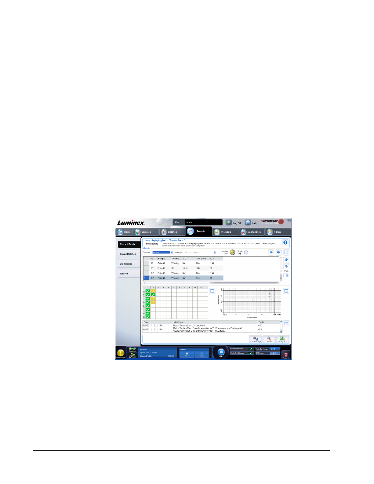
Chapter 4: Results Page
Results Page Functionality
Results > Current Batch
Once data is collected in a batch, observation and analysis take place in the Results page.
This page contains the following tabs:
55
Page 69

• Current Batch - View statistics for the current run and progress per well.
• Saved Batches - View information about already processed batches and, if necessary,
replay them or recalculate their data.
• Click Open from the Saved Batches tab to view the following subtabs:
• Results
• Settings - Shows the report type you selected
• Log - Information about acquisition
• Sample Details - Details about the sample
• Click Replay > Recalculate Data from the Saved Batches tab to view the following
subtabs:
• Protocols
• Stds & Ctrls
• Plate Layout
• Click Replay > Replay Batch from the Saved Batches tab to view the following
subtabs:
• Settings - Shows the report type you selected
• Analytes
• Stds & Ctrls
• Plate Layout
• LIS Results - View a batch or transmit a batch that contains LIS results.
• Reports - This tab enables you to select a report to view:
• Batches Reports
• Protocols Reports
• Calibration and Verification Reports
• Performance Verification Reports
• System Log Reports
• Advanced Reports
• Data Interpretation
• Batch Settings
• Plate Layout
• Batch Audit
• Patient Report
Performing Analysis
If you are using a third-party software to perform analysis, see the user manual provided with
that software.
NOTE: Luminex recommends using median statistics for data analysis.
xPONENT for MAGPIX 4.2 Software User Manual
56
Page 70

You can direct the system to acquire samples in replicate regardless of batch type. For
qualitative batches, qualitative results for replicates are averaged and the reported
interpretation is determined from this replicate average.
Replicates in quantitative batches are based on a standard curve that is generated by either
the “Fit of all standards” or “Mean of replicates”. The default is “Fit of all standards”. Unknown
samples are calculated from the standard curve. Test results for replicate samples are
averaged to determine the reported quantitative result denoted as “AVG”.
You can analyze an acquired batch using the analysis features of Qualitative, Quantitative,
and Allele Call algorithms.
Qualitative Analysis - Determines results as either positive or negative, reactive or nonreactive, and so on. The system is flexible in defining custom result ranges, such as negative,
low positive, and high positive.
Quantitative Analysis - Determines the sample concentrations from standard curves using
regression methods, such as 4P or 5P logistic curve fitting. There are two main assay types:
non-competitive and competitive. In a non-competitive assay, the slope of a concentration
versus Median Fluorescent Intensity (MFI) standard curve is a positive number. That is, low
concentrations result in low MFIs and high concentrations result in high MFIs. Conversely,
competitive assays generate a standard curve with a negative slope, the endpoints of which
are high MFI/low concentration on the left, and low MFI/high concentrations on the right.
Allele Call - Compares groups of analytes in order to determine genotype. Groups can
include two, three, or four analytes for comparison. Set the call rate to determine what ratio
you want to set as the limit for the analyte comparison.
Current Batch Tab
Results > Current Batch
Use this tab to view results, statistics, and log information related to the current batch, and to
perform statistical analysis on batch results. This tab offers real-time monitoring of batch
sampling during acquisition through a display of sample bead statistics and analytes, and dot
Results Page
57
Page 71

plot data. The statistics available on this tab are intrawell bead statistics. They do not
describe replicate well assay results.
There are four maximize buttons in this window, one for each major pane. Click the
appropriate one to maximize the pane. After clicking, the clicked button becomes a minimize
button. Click minimize to return the pane to its standard size.
NOTE: The buttons on this tab change based on settings chosen on other
application pages.
This tab has the following features:
xPONENT for MAGPIX 4.2 Software User Manual
58
Page 72

• Statistic - To view a particular statistic for analytes in a batch, select one of the options on
the drop-down list. The statistical options displayed change according to the type of
analysis.
NOTE: Trimmed statistics (indicated by *) remove the lower and upper five
percent of the extreme statistic values, then use the remaining
values for the Mean, Standard Deviation, or %CV calculations. The
point of a trimmed statistic is that it removes outliers, ensuring that
the data is more representative of the population.
• Median (MFI) - The value (detected signal) that is in the middle of the microsphere
population when sorted by reporter value lowest to highest. The mediam value is much
less sensitive than the mean value to outliers and carryover.
• Test Result - The calculated analysis value for quantitative or qualitative assays derived
from standards with known values.
• Range - A semi-quantitative result for a particular numerical result falling between a
predefined set of values such as Normal or Negative.
• Count - The number of microspheres detected within the specified microsphere region.
Microspheres that are not inside the region on the dot plot are not included.
• Net MFI (Sample Well MFI - Background Well MFI)) - The NetMFI can be used to
eliminate the effect of background signal in an assay.
• Mean - Average of all values for the microspheres detected in a region.
• % CV of microspheres - The measure of relative dispersion within the distribution.
%CV = 100 x Std Dev / Mean
• Standard Deviation - For calculating sample variability or dispersion, Luminex uses the
standard deviation formula.
• Peak - The value that is equal to the largest number of data points within the distribution.
For example, in data set {1,2,2,3,3,3,4,5}, 3 is the peak because it occurs the most
frequently in the distribution list.
• Trimmed Count*
• Trimmed Mean*
• Trimmed%CV of microspheres*
• Trimmed Standard Deviation*
• Trimmed Peak*
• % CV of Replicates - The measure of relative dispersion within the distribution of results
for replicate samples.
%CV = 100 X Std Dev / Mean
• % Recovery - A measure of how accurately your observed results match your expected
results following regression analysis.
(Observed concentration) / (Expected concentration) x 100%
• Expected Result - The known or expected test result value for a standard or control.
• Control Range - Low - The lowest value for an assay control used to determine pass/
fail criteria for an assay.
Results Page
59
Page 73

• Control Range - High - The highest value for an assay control used to determine pass/
fail criteria for an assay.
• Normalized Net Median - For each analyte in a well the Normalized Net Median (NNM)
= (net median of analyte) / (net median of normalization bead)
• Units - The unit of measure for an analyte, for example, pg/mL.
• Analyte - Contains a list of analytes run in the batch. Select an analyte to view all statistics
for that analyte.
• Well(s) to View
• Current Well - Displays the statistics of the well currently being displayed (This changes
to Displayed Well if viewing a batch using the Open button of the Saved Batches tab).
• Single Step - Instrument analyzes one well at a time. Click to turn function on or off.
This is useful to run prior to running an entire batch to confirm that the system is set up
correctly.
• Results pane - Displays statistics related to the batch.
• Use the up, down, left, and right arrow buttons to move through the table, or use the
scroll bars.
• Plate - Select the plate you want to view, if there is more than one plate.
CAUTION: If using multiple plates, ensure that plates are used in the proper
order. Failure to do so can result in inaccurate data and test
results.
• Well Report pane - This pane displays a representation of the plate and the status of
acquired wells. Each well displays one of three possible states:
• Yellow - Well acquired, but the system detects a possible problem (select the Log tab
for more information).
• Green - Well acquired successfully.
• Red - Well acquisition unsuccessful, the system might have stopped, depending on the
circumstances (select Log tab for more information).
• Dot Plot pane - The default location of the dot plot is the lower-right section of the Current
Batch tab. The dot plot is a graphical display of real-time data collection. The dot plot
default display when using 1 to 50 beads shows Classification 1 (CL1) and Classification
2 (CL2). Click within the dot plot to open Display Mode, with its two options:
• Logarithmic. This is the default option.
• Linear
• Log pane - This displays a log of system processes. Log entries indicating warnings are
highlighted in yellow; errors are highlighted in red. Other log entries are not highlighted.
The log includes the following information:
• Date
• Message
• Code
• Save Image - Opens a Save As dialog box to save a screen capture.
• Details - Opens the Results tab, enabling more analysis and results.
xPONENT for MAGPIX 4.2 Software User Manual
60
Page 74

• Progress - Click to display real-time progress of the well acquisition. Analyte counts are
displayed in a dynamic bar graph as they are acquired. The scroll bar at the bottom of the
Progress display scrolls through the analyte list. A zoom feature on the left of the display
enables you to enlarge the image.
• Default - Appears only when the progress display is active. Click to return to the dot plot
display.
Saved Batches Tab
Results > Saved Batches
Use this tab to open a batch that has been run and view its details, and to export, approve, or
replay a batch.
The Saved Batches tab has 4 subtabs:
• Click the Results subtab to view statistical information about the batch.
• Click the Settings subtab to view the batch settings report.
• Click the Log subtab to view a log for the activity that occurred during acquisition of the
selected batch.
• Click the Sample Details tab to view sample details for each sample in the batch.
When the Saved Batches tab opens, it includes the following features:
Results Page
61
Page 75

• Filter - Click Filter to open the Filter Setup dialog box.
This dialog box lets you choose the saved batches you want to display in the Completed
Batches list, based on options you select or clear in these check boxes:
• Batch Name
• Protocol
• Batch Status
• Lot ID
• Kit ID
• Analyte
• Sample ID
• First Name
• Last Name
• User ID
• Date
• Reset - Clears all check boxes.
• OK - Closes the dialog box and applies any changes you made.
• Cancel - Closes the dialog box and cancels any changes that you made.
When you fill in the Filter Setup box and click OK, the message Filter is on is displayed
on the Saved Batches page. To turn off the filter, click Clear.
• Completed Batches table - This displays a list of completed batches, including the Name,
Protocol, Protocol Version, Date, Status, and User information for each batch. This list
does not include batches that have not been run.
xPONENT for MAGPIX 4.2 Software User Manual
62
Page 76

• Save Prtcl - Opens the Save Protocol dialog box, displaying the kit information for the
selected batch.
• Plate Layout - Opens the Report dialog box, which contains the Batch Plate Layout
Report.
• Approve - Opens the Batch Approval Confirmation dialog box to approve the selected
batch.
Only approved batches can be transmitted to the LIS. If your software is licensed for LIS
use, you can transmit batches to the LIS from the Sample Results tab. After you have
approved a batch, the status of the batch changes to Approved in the Complete Batches
list.
• Exp Results - Opens the Save As dialog box to choose an export destination for the .CSV
file containing your results.
NOTE: If you plan to replay this batch in the future, be sure to include the
raw (lxb) files.
• Import - Opens the Open dialog box so you can select a batch file (.mdf) to import. Select
Include Raw Files (LXB) to include raw files in the import. Select Overwrite to overwrite
existing files.
• Export - Opens the Export Batch dialog box, where you can choose a location for the file
you selected to export. Select Include Raw Files (LXB) to include raw files in the export.
Select Overwrite to overwrite existing files.
Results Page
63
Page 77

• Replay - Opens the Select Replay Mode dialog box. This box enables you to use the data
stored in the run files from the initial acquisition to reprocess a batch, creating a new batch
output file. A batch can be reprocessed multiple times. When you replay or recalculate a
batch, you perform the same steps to create the batch as you did when you created the
batch the first time. This sequence varies based on whether or not you created a new
batch from a new protocol or a new batch from an existing protocol. The initial batch data
and output file always remain intact and unchanged. Each time you replay a batch, the
system handles it as if it is new data, and creates a separate batch entry and output file.
• Replay batch - Use to replay raw bead data files. The bead data files are replayed
using the gate, analyte, analysis settings, and plate layout that were selected in the new
or updated protocol. Settings such as bead type, volume, timeout, XY heater, and report
gain have no effect on the replayed results.
• Recalculate data - Reanalyze the batch results using only the batch MFI values. The
batch MFI values are recalculated using the analysis settings and plate layout selected
in the new recalculated batch or protocol. Settings such as bead type, volume, timeout,
XY heater, and report gain have no effect on the replayed results. Because only the MFI
values are reanalyzed, no data is displayed in the dot plot.
• OK - Saves your changes.
• Cancel - Cancels your changes and closes the box.
• Open - Opens the Results tab. Use this tab to view the saved batch results for the
selected batch. When you click Open, the buttons change:
• Save Image - Opens a Save As dialog box to save a screen capture.
• Formula - Opens the Change Analysis dialog box with a list of analytes used in the
batch.
xPONENT for MAGPIX 4.2 Software User Manual
64
Page 78
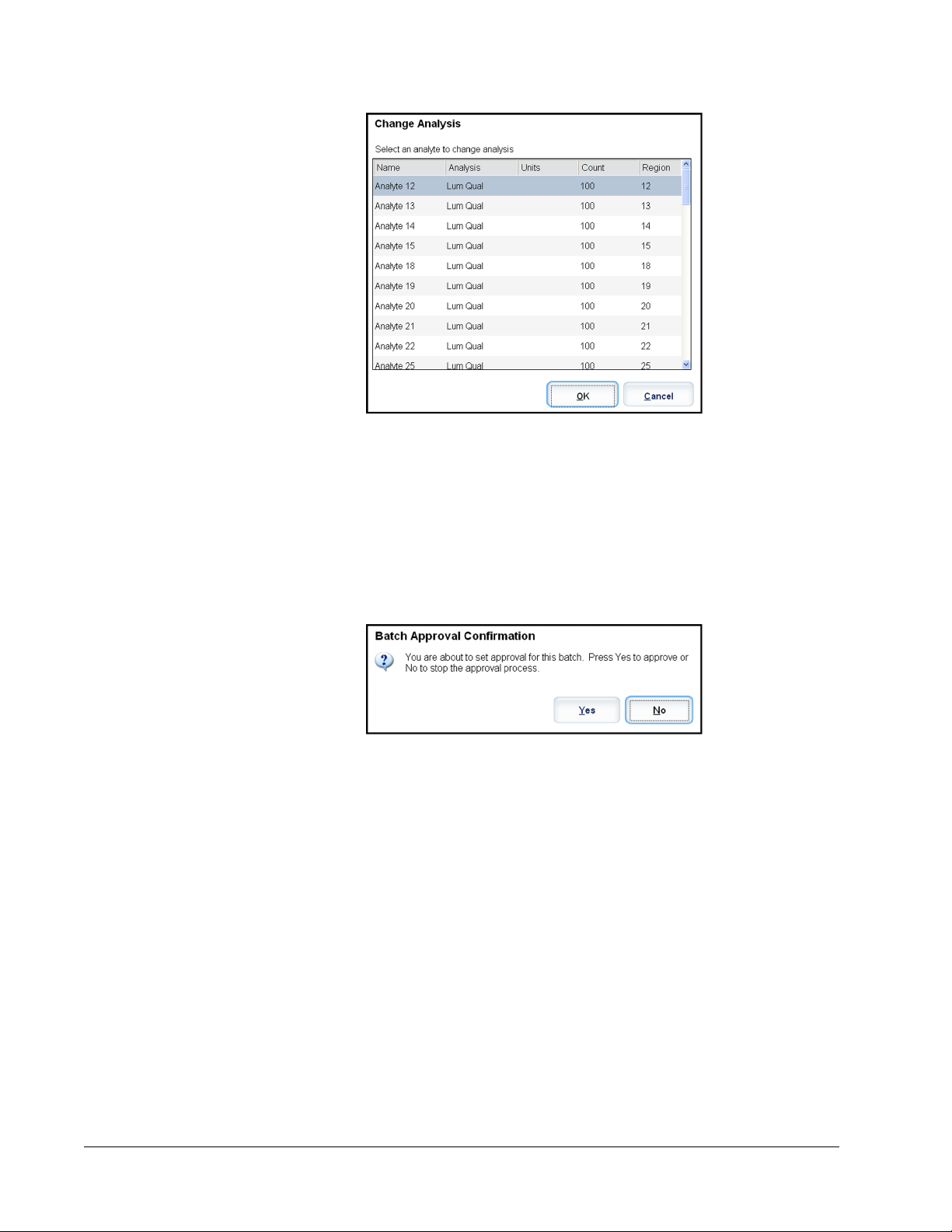
Click an analyte to open the Analysis Settings dialog box from which you can select a
new analysis setting for the analyte.
• Progress - Click to display real-time progress of the well acquisition. Analyte counts are
displayed in a dynamic bar graph as they are acquired. The scroll bar at the bottom of
the Progress display scrolls through the analyte list. A zoom feature on the left of the
display enables you to enlarge the image.
• Approve - Opens the Batch Approval Confirmation dialog box, which contains the
data for analytes selected in the Results tab. Click Yes to approve the batch. The dialog
box confirms the approval.
• Validate - Validates an entire selected row or cell in the Results table. Average rows or
cells cannot be selected. If you haven’t selected an item or the item you selected does
not need to be validated, a warning dialog box displays.
• Invalidate - Invalidates an entire selected row or cell in the Results table. The selection
will turn red when invalidated. Select the same item and click Validate to remove the
invalidation status.
• Close - Closes the batch and reopens the Saved Batches tab.
Replaying a Batch
Replay batch uses the raw bead data files from the initial acquisition to reprocess the batch,
and creates a new batch output file. The bead data files are replayed using the analyte,
analysis settings, and plate layout selected in the new batch or protocol. Settings such as
bead type, Volume, and XY Heater have no effect.
Results from replaying a batch are generated in the usual manner, with new .lxb and CSV
files.
Results Page
65
Page 79
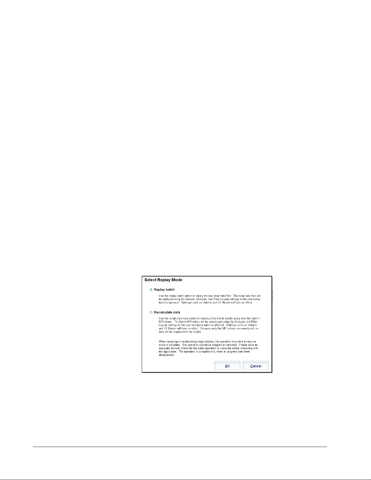
Replaying or recalculating a large batch can take 1 hour or more to complete. Batch replay
cannot be stopped while in progress. Allow adequate time for the operation to complete. The
operation is complete when all progress bars have disappeared.
A batch can be reprocessed multiple times. If the system crashes but the plate finished, the
data can be recovered by replaying the batch.
The initial batch data and output file always remain intact and unchanged. Each time you
replay or recalculate a batch, the system handles it as if it is a new batch, creating a separate
batch entry and output file.
If you select to replay or recalculate a batch that was originally run without a saved protocol,
you have to modify the settings on the following subtabs:
• Settings
• Analytes
• Stds & Ctrls
• Plate Layout
These subtabs appear under the Saved Batches tab. After you have completed them in
order, click Replay Batch on the Plate Layout subtab to perform the replay or recalculate
procedure.
Selecting Replay Mode
1. Open the Results page, then the Saved Batches tab.
2. Select the batch that you want to replay and click Replay at the bottom of the screen.
This opens the Select Replay Mode dialog box. By default, Recalculate data is
selected.
3. Select Replay batch or Recalculate data.
The information that you must enter to replay or recalculate is the same.
4. Select the correct protocol and click Next.
5. Select the wells to be acquired and click Replay Batch.
Results Subtab
Results > Saved Batches > Results
xPONENT for MAGPIX 4.2 Software User Manual
66
Page 80

This subtab displays the following features:
There are three maximize buttons in this window, one for each major pane. Click the
appropriate one to maximize the pane. After clicking, the clicked button becomes a minimize
button. Click minimize to return the pane to its standard size.
This tab has the following features:
Results Page
67
Page 81

• Statistic - To view a particular statistic for analytes in a batch, select one of the options on
the drop-down list. The statistical options displayed change according to the type of
analysis.
NOTE: Trimmed statistics (indicated by *) remove the lower and upper five
percent of the extreme statistic values, then use the remaining
values for the Mean, Standard Deviation, or %CV calculations. The
point of a trimmed statistic is that it removes outliers, ensuring that
the data is more representative of the population.
• Median (MFI) - The value (detected signal) that is in the middle of the microsphere
population when sorted by reporter value lowest to highest. The mediam value is much
less sensitive than the mean value to outliers and carryover.
• Test Result - The calculated analysis value for quantitative or qualitative assays derived
from standards with known values.
• Range - A semi-quantitative result for a particular numerical result falling between a
predefined set of values such as Normal or Negative.
• Count - The number of microspheres detected within the specified microsphere region.
Microspheres that are not inside the region on the dot plot are not included.
• Net MFI (Sample Well MFI - Background Well MFI)) - The NetMFI can be used to
eliminate the effect of background signal in an assay.
• Mean - Average of all values for the microspheres detected in a region.
• % CV of microspheres - The measure of relative dispersion within the distribution.
%CV = 100 x Std Dev / Mean
• Standard Deviation - For calculating sample variability or dispersion, Luminex uses the
standard deviation formula.
• Peak - The value that is equal to the largest number of data points within the distribution.
For example, in data set {1,2,2,3,3,3,4,5}, 3 is the peak because it occurs the most
frequently in the distribution list.
• Trimmed Count*
• Trimmed Mean*
• Trimmed%CV of microspheres*
• Trimmed Standard Deviation*
• Trimmed Peak*
• % CV of Replicates - The measure of relative dispersion within the distribution of results
for replicate samples.
%CV = 100 X Std Dev / Mean
• % Recovery - A measure of how accurately your observed results match your expected
results following regression analysis.
(Observed concentration) / (Expected concentration) x 100%
• Expected Result - The known or expected test result value for a standard or control.
• Control Range - Low - The lowest value for an assay control used to determine pass/
fail criteria for an assay.
xPONENT for MAGPIX 4.2 Software User Manual
68
Page 82

• Control Range - High - The highest value for an assay control used to determine pass/
fail criteria for an assay.
• Normalized Net Median - For each analyte in a well the Normalized Net Median (NNM)
= (net median of analyte) / (net median of normalization bead)
• Units - The unit of measure for an analyte, for example, pg/mL.
• Analyte - Contains a list of analytes run in the batch. Select an analyte to view all statistics
for that analyte.
• Displayed Well - Displays the n;umber of the well whose contents currently appear in the
table.
• Results pane - Displays statistics related to the batch.
• Use the up, down, left, and right arrow buttons to move through the table, or use the
scroll bars.
• Plate - Select the plate you want to view, if there is more than one plate.
CAUTION: If using multiple plates, ensure that plates are used in the proper
order. Failure to do so can result in inaccurate data and test
results.
• Well Report pane - This pane displays a representation of the plate and the status of
acquired wells. Each well displays one of three possible states:
• Yellow - Well acquired, but the system detects a possible problem (select the Log tab
for more information).
• Green - Well acquired successfully.
• Red - Well acquisition unsuccessful, the system might have stopped, depending on the
circumstances (select Log tab for more information).
• Dot Plot pane - The default location of the dot plot is the lower-right section of the Current
Batch tab. The dot plot is a graphical display of real-time data collection. The dot plot
default display when using 1 to 50 beads shows Classification 1 (CL1) and Classification
2 (CL2). Right click within the dot plot to open Display Mode, with its two options:
• Logarithmic. This is the default option.
• Linear
• Save Image - Opens a Save As dialog box to save a screen capture.
• Formula - Opens the Change Analysis dialog box with a list of analytes used in the batch.
Click an analyte to open the Analysis Settings dialog box from which you can select a
new analysis setting for the analyte.
• Progress - Click to display real-time progress of the well acquisition. Analyte counts are
displayed in a dynamic bar graph as they are acquired. The scroll bar at the bottom of the
Progress display scrolls through the analyte list. A zoom feature on the left of the display
enables you to enlarge the image.
• Approve - Opens the Batch Approval Confirmation dialog box, which contains the data
for analytes selected in the Results tab. Click Yes to approve the batch. The dialog box
confirms the approval.
• Validate - Validates an entire selected row or cell in the Results table. Average rows or
cells cannot be selected. If you haven't selected an item or the item you selected does not
need to be validated, a warning dialog box displays. Your xPONENT system administrator
must give you privileges to invalidate standards if you are using the Secure xPONENT
package.
Results Page
69
Page 83

• Invalidate - Invalidates an entire selected row or cell in the Results table. The selection will
turn red when invalidated. Select the same item and click Validate to remove the
invalidation status.
• Close - Closes the batch and reopens the Saved Batches tab.
Validate Standards
Your xPONENT® system administrator must give you privileges to validate standards if you
are using the Secure xPONENT package. All standards are assumed to be valid unless
explicitly invalidated.
1. Open the Results page.
2. Open the Saved Batches tab.
3. Click the batch name, then click Open. The Results tab opens.
4. Click the square area next to left of the standard you wish to validate, then click Validate.
Invalidate Standards and Controls
NOTE: It is possible to invalidate or remove a control in data analysis.
However, Luminex does not recommend invalidating controls.
For information on assay controls and guidelines regarding accepting or rejecting control
values, contact the assay kit manufacturer.
To invalidate standards and controls:
1. Open the Results page, then open the Saved Batches tab.
2. Open the Saved Batches tab.
3. Click the batch name, then click Open. The Results tab opens.
4. Click the square area to the left of the well you wish to invalidate, then click Invalidate.
The whole row turns red.
Settings Subtab
Results > Saved Batches > Settings
xPONENT for MAGPIX 4.2 Software User Manual
70
Page 84

When you click the Settings subtab on the Saved Batches page, a report opens. This report
displays:
• A date and time stamp at the top of the report
• < and > scroll buttons so that you can view pages in the report
• Calibration State
• Machine Information
• Assay Lots Used
Viewing Batch Settings
1. Open the Results page, then open the Saved Batches tab.
2. Click Saved Batches, then click the batch for which you want to view details.
3. Click Open, then click the Settings tab.
4. Click the left and right Page arrows to view the pages of the batch settings report.
5. Click Save to open the Save As dialog box. Navigate to the location where you want to
save the batch settings report, and click Save.
Log Subtab
Results > Saved Batches > Log
Results Page
71
Page 85
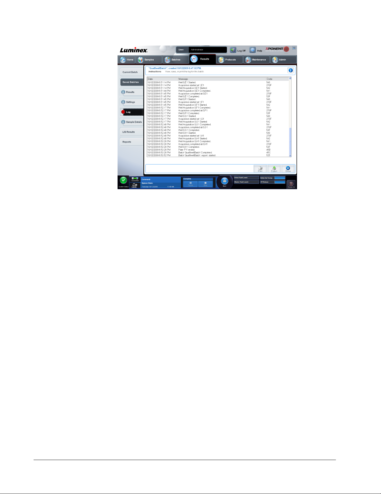
This tab displays a log of the activity which occurred during the acquisition of the selected
batch; you can print the log.
The following information is displayed about each activity:
• Date
• Message
• Code
Log entries display yellow if a well was acquired but there was a possible problem, and red if
acquisition failed.
• Print - Prints the log.
• Export - Opens the Save As dialog box to save the batch log file. Select a location and
click Save.
• Close - Reopens the Saved Batches tab.
Viewing Batch Logs
1. Open the Results page, then open the Saved Batches tab.
2. Click Saved Batches, then click the batch for which you want to view details.
3. Click Open. The Results tab opens.
4. Click Log to open the Log tab.
Sample Details Subtab
Results > Saved Batches > Sample Details
xPONENT for MAGPIX 4.2 Software User Manual
72
Page 86

• < and > Arrows - Scroll left to right through the sample details.
• ^ and v Arrows - Scroll up and down through the sample details.
• Transmit - For systems configured for LIS transmission, select a single analyte or the
entire sample and click Transmit to send the results.
• Close - Reopens the Saved Batches tab.
In addition, the following information is shown on this tab:
• SampleID
• Samples Status
• Analyte
Viewing Sample Details
1. Open the Results page, then open the Saved Batches tab.
2. Click Saved Batches, then click the batch for which you want to view details.
3. Click Open, then click Sample Details. The Sample Details tab opens. If you are using
an LIS licensed package of the software, click Transmit to transmit sample details to the
LIS database. You can transmit either a single analyte per sample or the entire sample.
LIS Results Tab
This tab displays information about saved batches that contain LIS samples.
Results > LIS Results
Results Page
73
Page 87
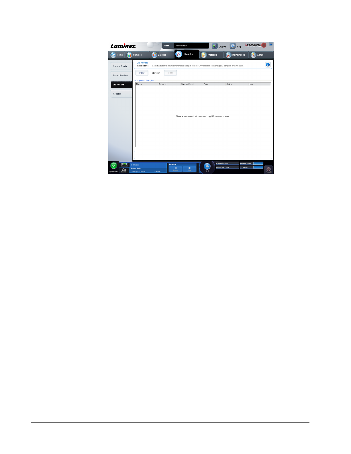
• Filter - Opens the Filter Setup dialog box.
Batch-Specific Details
• Batch Name
• Protocol
• Batch Status
• Lot ID
• Kit ID
• Analyte
Sample Details
• SampleID
• First Name
• Last Name
Others
• User ID
• Date
• Reset
• OK / Cancel
• Clear - Click to turn off the filter.
• Completed Samples - Displays Name, Protocol, Sample Count, Date, Status, and User
information for each batch displayed in this list.
• Transmit - Transmits a batch to a LIS if xPONENT is connected to one.
• Details - Opens the Sample Details tab to view sample results.
xPONENT for MAGPIX 4.2 Software User Manual
74
Page 88

Reports Tab
Results > Reports
Use this tab to view, generate, and print reports.
• Report and Type lists - Report lists the categories of reports. The selections in the Type
list change depending on the selection you made from the Report list. Depending on the
choice you make, various other changes occur on the Reports tab:
• Batch Reports - A list of batches opens, so that you can select one. In addition, a
Select Analytes box opens to the right of the reports list. You can select the analytes you
want to include. Select them all using the All button; clear your selections using the
Clear button.
NOTE: If running a data interpretation of an allele call batch report, be aware
that when choosing analytes from the Select Analytes list, selecting
one analyte selects all analytes in that group.
• Protocol Reports - A list of protocols opens, so that you can select one.
• Calibration and Verification Reports - A Start field and a Through field open. Use
these to define the date range.
• Performance Verification Reports - A Start field and a Through field open. Use these
to define the date range.
• System Log Reports - A Start field and a Through field open. Use these to define the
date range.
• Advanced Reports
• Generate - Use this button to generate the report.
After you click Generate, additional buttons are displayed or can be displayed, depending on
the nature and size of the report:
Results Page
75
Page 89

• Select Analyte arrows - This feature is directly below the Report list. Use the left and right
arrows to display information for individual analytes of those selected for the report.
• Page arrows - Use the arrows to scroll through the pages being displayed.
• Save All - Click to open the Browse For Folder dialog box. Select a location to save the
file, and click OK. This file includes all selected analytes.
• Print All - Click to print the analyte information for all the analytes in the report.
• Save - Click to open the Save As dialog box. Select a location and click Save. This saves
only the analyte information currently displayed.
• Print - Click to print the analyte information currently being viewed.
• New Report - Click to return to the main Reports window.
Generating a Report
1. Open the Results page, then the Reports tab.
2. In the Report drop-down list, select the category of report: batch, protocol, calibration
and verification, performance verification, system log, or advanced. Depending on what
you choose in the Report list, the content of the Type list changes and other features can
be displayed in the window.
3. Select the specific report from the Type list.
4. If you selected either a batch report or a protocol report, select the specific batch or
protocol from the list.
5. If the report you selected requires a date range (calibration and verification, performance
verification, and system log), use the calendars available when you click the Start and
Through buttons to establish the date range.
6. If the report you selected requires a choice of analytes, select them from the Select
Analytes box. Select them all using the All button; clear your selections using the Clear
button.
7. Click Generate.
If the report includes multiples analytes, use the arrows above the report to move through the
list of analytes.
If the report is lengthy, use the Page arrows to scroll through the pages in the report.
Use the Zoom button to focus on a particular part of the report.
xPONENT for MAGPIX 4.2 Software User Manual
76
Page 90

Chapter 5: Protocols Page
Protocols Page Functionality
Protocols > Protocols
The Protocols page enables you to create or import a new protocol, or select an existing
protocol from the Installed Protocols list.
The following installed protocol information is shown on this page:
• Name
• Version
• Manufacturer
• Date
Click the Create New Protocol button or click Stds/Ctrls to move to those pages.
77
Page 91

There are action buttons at the bottom of the page. Most of these buttons are not displayed
unless you are working with a saved protocol. While you are creating a protocol, only Cancel
and Next buttons are displayed. After saving a protocol or opening a saved protocol, the
following buttons are displayed:
• New Std/Ctrl
• Plate Layout
• Delete
• Import
• Export
• Edit
• View
Protocol Procedures
Creating an Allele Call Protocol
Protocols > Protocols > Create New Protocol
This protocol contains no standards or controls. An allele call protocol compares groups of
two, three, or four analytes to identify genotypes.
To create an allele call protocol:
1. Open the Protocols page, then open the Protocols tab. Click Create New Protocol.
The Protocol Settings tab opens.
2. In the Name box, type the name of the protocol.
3. In the Description box, type a description of the protocol.
4. In the Version box, type the version of the protocol.
5. In the Manufacturer box, type the manufacturer information for the protocol.
6. Define the settings in the Acquisition Settings section.
NOTE: Final washes are required for proper analysis. If you are not
performing a final wash step on your plate before acquisition on the
MAGPIX instrument, enable Sample Wash here. This automatically
washes each sample.
7. Define settings in the Analysis Settings section, selecting Allele Call as the analysis
type.
8. Click Next. The Analytes tab opens.
9. Click the desired analyte (bead ID) in the numbered grid. Information about the analytes
is displayed in a list on the right side of the grid. For an allele call analysis, you must
select a group of two, three, or four analytes.
10. Click Group to group analytes for the allele call. The grouped analytes display in a list to
the right. Select more analytes and then click Group again if you want to add another
group to the analysis.
11. Click and type an analyte name in the Name column to the right of the analyte grid.
12. In the Count box, type the desired bead count for each analyte. Click Apply All.
xPONENT for MAGPIX 4.2 Software User Manual
78
Page 92

13. To set a bead count and the units for a single analyte, click in the Units and Count
columns directly to the right of the analyte grid, and type a units value and bead count.
14. Click in the Call % column and type a value to set an individual analyte's call percentage.
15. Click Next. The Plate Layout tab opens.
• To add well commands, select the appropriate wells and mark them as unknown,
standard, control, background, or wash. You can also delete commands that you've
added and change the starting location on the plate. If you want to run in replicate,
change the Replicate Count to the appropriate number and the Grouping to your
preferred grouping method.
• Delete a command by clicking the well, and clicking Delete. The Delete Options
dialog box opens. Select Delete just the selected wells to delete a single well
command, or Delete all wells containing these samples to delete all wells with the
same command.
NOTE: The Post Batch routine runs after the batch is complete. This routine
is selected by default when the protocol or batch is set up. The
default Post Batch routine can be changed in the Batch Options
tab of the Admin page.
NOTE: For more information about the commands and settings on the Plate
Layout tab, see the Plate Layout Tab.
Creating a Quantitative Assay Protocol
The protocol must contain multiple standards. The standards are assigned lot value
information for each test. A standard curve is generated according to the lot values. Including
controls in the protocol is optional, but recommended for judging the acceptability of batch
results.
To create a quantitative assay protocol:
1. Open the Protocols page, then open the Protocols tab. Click Create New Protocol.
The Settings tab opens.
2. In the Name box, type the name of the protocol.
3. Type a description in the Enter optional description here box.
4. In the Version box, type the version of the protocol.
5. In the Manufacturer box, type the manufacturer information for the protocol.
6. Define settings in the Acquisition Settings section.
7. Define settings in the Analysis Settings section, selecting Quantitative as the analysis
type. The protocol for a quantitative assay must contain multiple standards. Controls are
optional in a quantitative assay protocol.
8. Click Next. The Analytes tab opens.
9. Click the desired analytes (bead ID) in the numbered analyte grid. Information about the
analyte displays to the right side of the grid.
10. Click and type an analyte name in the Name column to the right of the analyte grid.
11. Click and type the desired unit of measurement in the Units box to the left of the Apply
All button.
12. Click and type the desired bead count for each analyte in the Count box. Click Apply All.
Protocols Page
79
Page 93

13. To set a bead count and the units for a single analyte, click in the Units and Count
columns directly to the right of the analyte grid, and type a bead count and units value.
14. To change the default analysis for all analytes, click Change. The Analysis Settings
dialog box opens.
15. In the Analysis Settings dialog box, select the analysis method from the Method list,
and the weighting in the Weight Type list. Click Apply to All Analytes to apply the
selection to all analytes.
16. To change the analysis for a single analyte, click the Analysis field for the analyte you
want to modify. The Analysis Settings dialog box opens.
17. Select an analysis method in the Method list.
18. Select a weight type in the Weight Type list (Weight Type may not display, depending
on the analysis method selected in the Method list).
19. Check Mark as Intra-Well Normalization Bead if you want to use the analyte as a
normalization bead. The normalization bead is a microsphere set that is included in the
assay as an internal control. It controls for sample variation and can be used to normalize
data between samples in a run.
20. Check Use Threshold Ranges if you want to use a range for the analysis.
21. Click Add Range to setup the threshold range.
22. Type a name for the range in the Range Name field.
23. Type low and high range values in the Low Value and High Value fields.
24. Select the check box in the Inclusive column to include the value in the range, or leave it
clear to make the range value one unit higher than the low value, and one unit lower than
the high value.
25. Highlight a range and click Delete Range to delete the range.
26. Click OK to apply the new settings to the analyte first clicked, or Apply to All Analytes to
apply them to all the analytes in the protocol.
xPONENT for MAGPIX 4.2 Software User Manual
80
Page 94

27. Click Next. The Plate Layout tab opens.
• To add well commands, highlight the appropriate wells and mark them as unknown,
standard, control, background, or wash. You can also delete commands that you have
added and change the starting location on the plate. If you want to run in replicate,
change the Replicate Count to the appropriate number and the Grouping to your
preferred grouping method.
NOTE: Select the Replicate Count and Grouping settings before adding a
well command.
• To add maintenance commands, choose a command from the list. Highlight the well
that you want to apply it to, and then choose Pre Batch Routine or Post Batch
Routine. The Commands and Routines dialog box opens.
If you are working with more than one plate, choose Add & Change Plate. Here, you
can add a plate, change the order of the plates, and scroll through all plates.
• Delete a command by clicking the well, and clicking Delete. The Delete Options
dialog box opens. Select Delete just the selected wells to delete a single well
command, or Delete all wells containing these samples to delete all wells with the
same command.
• As you add commands to your plate, they appear in the Command Sequence list.
Type a well ID in the ID field. Here, you can give each of your wells an ID. You can
also import a protocol file by clicking Import List.
• Move commands up or down in the sequence by highlighting a command and using
the Move Command arrows to move the command up or down in the list.
28. Click Save.
NOTE: The Pre Batch routine runs before the batch begins. This routine is
selected by default when the protocol or batch is set up. The default
Pre Batch routine can be changed in the Batch Options page.
NOTE: The Post Batch routine runs after the batch is complete. This routine
is selected by default when the protocol or batch is set up. The
Protocols Page
81
Page 95

default Post Batch routine can be changed in the Batch Options
tab of the Admin page.
Creating a Qualitative Assay Protocol
You define each Qualitative assay protocol using a single kit. The kit must contain one
standard. The standard is assigned a “Quali” value for each test. Controls are optional, but
are recommended for judging the acceptability of batch results.
To create a Qualitative Assay Protocol:
1. Open the Protocols page, then open the Protocols tab. Click Create New Protocol.
The Settings tab opens.
2. In the Name box, type the name of the protocol.
3. In the Version box, type the version of the protocol.
4. In the Manufacturer box, type the manufacturer information for the protocol.
5. Define settings in the Acquisition Settings section.
6. Define settings in the Analysis Settings section, selecting Qualitative as the analysis
type. The protocol for a qualitative assay contains a single standard.
7. Click Next. The Analytes tab opens.
8. Click the desired analytes (bead IDs) in the numbered grid. Information about the analyte
displays in a list on the right side of the grid.
9. To change the Default Analysis, click Change. The Analysis Settings dialog box
opens.
10. In the Analysis Settings dialog box, click the analysis method from the Analysis
Method list. Click OK to change the default analysis to a single analyte. Click Apply to
All Analytes to apply the selection to all analytes. Skip this step if you do not want to
change the default analysis or if you chose No Analysis on the Settings tab.
11. In the Units box, type the desired unit of measurement.
12. In the Count box, type the desired bead count for each analyte. Click Apply All.
xPONENT for MAGPIX 4.2 Software User Manual
82
Page 96

13. Click Next. The Plate Layout tab opens.
• To add well commands, highlight the appropriate wells and mark them as unknown,
standard, control, background, or wash. You can also delete commands that you’ve
added, and change the starting location on the plate. If you want to run in replicate,
change the Replicate Count to the appropriate number and the grouping to your
preferred grouping method.
• To add maintenance commands, choose a command from the list. Highlight the well
that you want to apply it to, and then choose Pre Batch Routine or Post Batch
Routine. The Commands and Routines dialog box opens.
If you are working with more than one plate, choose Add & Change Plate. Here, you
can add a plate, change the order of the plates, and scroll through all plates.
14. Click Save.
Deleting a Protocol
1. Open the Protocols page, then open the Protocols tab.
2. Select a protocol.
3. Click Delete. The Delete Protocol dialog box opens.
4. Click Yes.
Editing a Protocol
1. Open the Protocols page, then open the Protocols tab.
2. Select a protocol.
3. Click Edit. The Settings tab opens.
4. Define settings and click Next. The Analytes tab opens.
5. Define analytes and click Next. The Plate Layout tab opens.
Protocols Page
83
Page 97

6. Define the plate layout.
7. Click Save.
Exporting a Protocol
1. Open the Protocols page, then open the Protocols tab.
2. Select a protocol.
3. Click Export. The Save as dialog box opens.
4. Select a location to export the file to, and click Save.
Importing a Protocol
1. Open the Protocols page, then open the Protocols tab. Click Import.
2. In the Open dialog box, navigate to the protocol file you want to import, then click Open.
3. The imported protocol displays in the Installed Protocols list.
Adding a New Lot for Protocol
1. Open the Protocols page, then open the Protocols tab. Click the protocol to which you
want to add a lot.
2. Open the Stds & Ctrls tab.
3. Click Create New Std/Ctrl Lots and select a protocol from the drop down list in the
Select Protocol dialog box, then click OK. The Std/Ctrl Details tab opens.
4. Click Apply Std/Ctrl Kit to associate a kit with the protocol. If you are not using a kit,
type the appropriate Standard and Controls information in the Assay Standard
Information and Assay Control Information sections.
5. Click Save.
Lots and Kits Procedures
Assay kits include standards and/or controls. After you enter the assay kit information, it can
be used in multiple protocols. However, you should create separate kits specifically for use
with each protocol. For assay reagents specified in protocols, you can create new lots, edit lot
information, select pre-existing lots for reuse, import lots, and export lots.
Once a lot is used, changing or modifying it will prompt you for a new lot name.
Creating a Lot
To create lots, you must use a protocol that uses either Quantitative or Qualitative analysis
settings.
To create a lot:
1. Open the Protocols page, then open the Protocols tab. Click the Stds & Ctrls tab, then
click Create New Std/Ctrl Lots.
2. In the Select Protocol dialog box, select the protocol you want to use for this lot, then
click OK. The Std/Ctrl Details tab opens.
xPONENT for MAGPIX 4.2 Software User Manual
84
Page 98

3. If the protocol uses standards, type the appropriate information for each standard in the
Assay Standard Information section. In each analyte column, type the expected
concentration for the analyte.
4. Alternatively, click Apply Std/Ctrl Kit and select a lot from the Select Lot dialog box.
Click OK to apply the lot.
5. If your batch uses controls, select Expected, Low, or High from the Show Value
options. Use the Apply Values arrows to apply values down or across the range of
analytes.
6. Click Save.
Editing a Lot
To edit a lot:
1. Open the Protocols page, then open the Protocols tab. Click the Stds & Ctrls tab.
2. In the Installed Kits And Lots section, select a lot and then click Edit. The Std/Ctrl
Details tab opens. Change the lot information as appropriate.
Deleting a Lot
To delete a lot:
1. Open the Protocols page, then open the Protocols tab. Click the Stds & Ctrls tab.
2. In the Installed Kits And Lots section, click the lot you want to delete, then click Delete.
Exporting a Lot
NOTE: Lots and kits can only be exported if the protocol they were originally
created with exists within the system. If the protocol has been
deleted, the lot or kit cannot be exported.
To export a lot:
1. Open the Protocols page, then open the Protocols tab. Click the Stds & Ctrls tab.
2. In the Installed Kits And Lots section, click the lot you want to export, then click Export.
The Save As dialog box opens.
3. Navigate to the location you want to export the file to, then click Save.
Importing a Lot
1. Open the Protocols page, then open the Protocols tab. Click the Stds & Ctrls tab, and
then click Import.
2. In the Open dialog box, navigate to the file, then click Open.
Creating a Kit
To create a kit:
1. Open the Protocols page, then open the Protocols tab.
2. Select the protocol that you want to use for the kit, then click New Std/Ctrl. The Std/Ctrl
Details tab opens.
Protocols Page
85
Page 99

3. Type the name of the kit in the Name box, the lot number in the Std/Ctrl Kit Lot# box,
the expiration date using MM/DD/YY format in the Expiration box, and the manufacturer
in the Manufacturer box.
4. Click Apply Std Lot if you want to apply a standard lot. The Select Lot dialog box opens.
Click a lot and select OK.
5. Click Apply Ctrl Lot to apply a control lot. The Select Lot dialog box opens. Select a lot
and click OK.
6. Alternatively, type the appropriate information in the Assay Standard Information and
Assay Control Information sections. The number of standards, controls, or both in
these sections is defined in the protocol. If your batch uses controls, select Expected,
Low or High from the Show Value options. Use the Apply Values arrows to apply
values down or across the range of analytes.
7. Click Save.
Protocols Tab
Protocols > Protocols
The following installed protocol information is shown on this page:
• Name
• Version
• Manufacturer
• Date
In addition, these action buttons are available at the bottom of the page:
• New Stds & Ctrls - Click this button to open the Std/Ctrls Details page.
• Plate Layout - Click to open the Plate Layout tab.
• Delete
xPONENT for MAGPIX 4.2 Software User Manual
86
Page 100

• Import
• Export
• Exit
• View
Settings Subtab
Protocols > Protocols > Settings
Click Create a New Protocol on the Protocols tab to open the Settings subtab.
Name and description boxes - Type the name and description in the appropriate box.
Acquisition Settings
• Volume - This is the volume the instrument aspirates into the system for analysis. Type the
desired sample volume in microliters. Use values from 20 to 200 µl. To avoid air intake,
add at least 25 µl to the sample well in addition to the sample size. The default value is 50
µl.
• XY heater - Select Enabled to enable the XY heater. In the box type the desired value in
degrees Celsius. The temperature range is 35° to 60° C.
CAUTION: Acquiring data before the heater has reached the proper
temperature can compromise test results.
• Plate name - The name assigned to the plate. You can select a different plate from the list.
• Sample wash - Select this option for assays without a final wash step prior to reading the
plate on the instrument. This automatically washes each sample within the instrument.
Final washes are required for proper analysis.
Analysis Settings - Use this section to set the analysis type, set the number of standards
and controls, select an external analysis program, and choose whether or not to analyze
results while acquiring samples.
Protocols Page
87
 Loading...