

Page 1
Quick Guide
xPONENT® for FLEXMAP 3D® Software
Version 4.2
Page 2

©
Luminex Corporation, 2012. All rights reserved. No part of this publication may be
reproduced, transmitted, transcribed, or translated into any language or computer language,
in any form or by any means without prior express, written consent of Luminex Corporation.
LUMINEX CORPORATION
12212 Technology Boulevard
Austin, Texas 78727-6115
U.S.A.
Voice: (512) 219-8020
Fax: (512) 219-5195
xPONENT® for FLEXMAP 3D® Software Version 4.2 Quick Guide
89-00002-00-402 Rev. A
July 2012
Luminex Corporation (Luminex) reserves the right to modify its products and services at any
time. This guide is subject to change without notice. Although prepared to ensure accuracy,
Luminex assumes no liability for errors or omissions, or for any damages resulting from the
application or use of this information.
The following are trademarks of Luminex Corporation: Luminex®, xMAP®, xTAG®,
xPONENT®, Luminex® SD™, Luminex® XYP™, MAGPIX®, FLEXMAP 3D®, MagPlex
®
Microspheres, MicroPlex®.
All other trademarks, including ProClin®, Cheminert®, Windows® Pentium® and Dell® are
trademarks of their respective companies.
xPONENT™ for FLEXMAP 3D
ii
®
Page 3

Table of Contents
StartingxPONENT®...............................................................................................................................1
Start-up Indicators .................................................................................................................................1
Common Daily Activities .................................................................................................................1
Software Overview ................................................................................................................................2
System Monitor ...............................................................................................................................3
Initial Startup .........................................................................................................................................4
Adjusting the Sample Probe Height ................................................................................................5
Revive After Storage Routine .........................................................................................................7
Initialize the System ........................................................................................................................7
Initialize the System ..............................................................................................................................8
Run, Save, and Print Reports .........................................................................................................9
Create a Protocol ................................................................................................................................10
Creating a Kit .......................................................................................................................................13
Create a Batch ....................................................................................................................................14
View Batches .......................................................................................................................................14
Shut Down the Instrument ...................................................................................................................15
Technical Support .........................................................................................................................15
iii
Page 4

xPONENT™ for FLEXMAP 3D
iv
®
Page 5

StartingxPONENT
• On the PC desktop, click the Luminex® xPONENT® icon, or click Start > All Programs >
Luminex > xPONENT > Luminex xPONENT.
• If you have a trial license, contact Luminex® Technical Support to obtain a full license, or
click OK in the dialog box to continue.
• If this is the first time you have started the software, the User License Agreement may
display. Read the license agreement. Select I accept the terms of this license
agreement, then click OK.
NOTE: For safety and legal information, refer to the xPONENT® for
FLEXMAP 3D ® Hardware Version 4.2 User Manual that you
received with your instrument.
Start-up Indicators
When you turn on the Luminex® FLEXMAP 3D® instrument, the following start-up indicators
occur:
• The blue light and power supply fan turn on
• The compressor and MAC valve cycle on (MAC valve makes a distinct sound)
• Immediately, the sample valve cycles (distinct sound)
• Immediately, the probe actuator cycles
• Immediately, the right syringe pump takes a stroke
• Immediately, the exhaust fans turn on
• The left syringe pump takes a stroke
• Drip to waste occurs
• The sample valve cycles again approximately 15 to 30 seconds after the left syringe pump
completes stroke
®
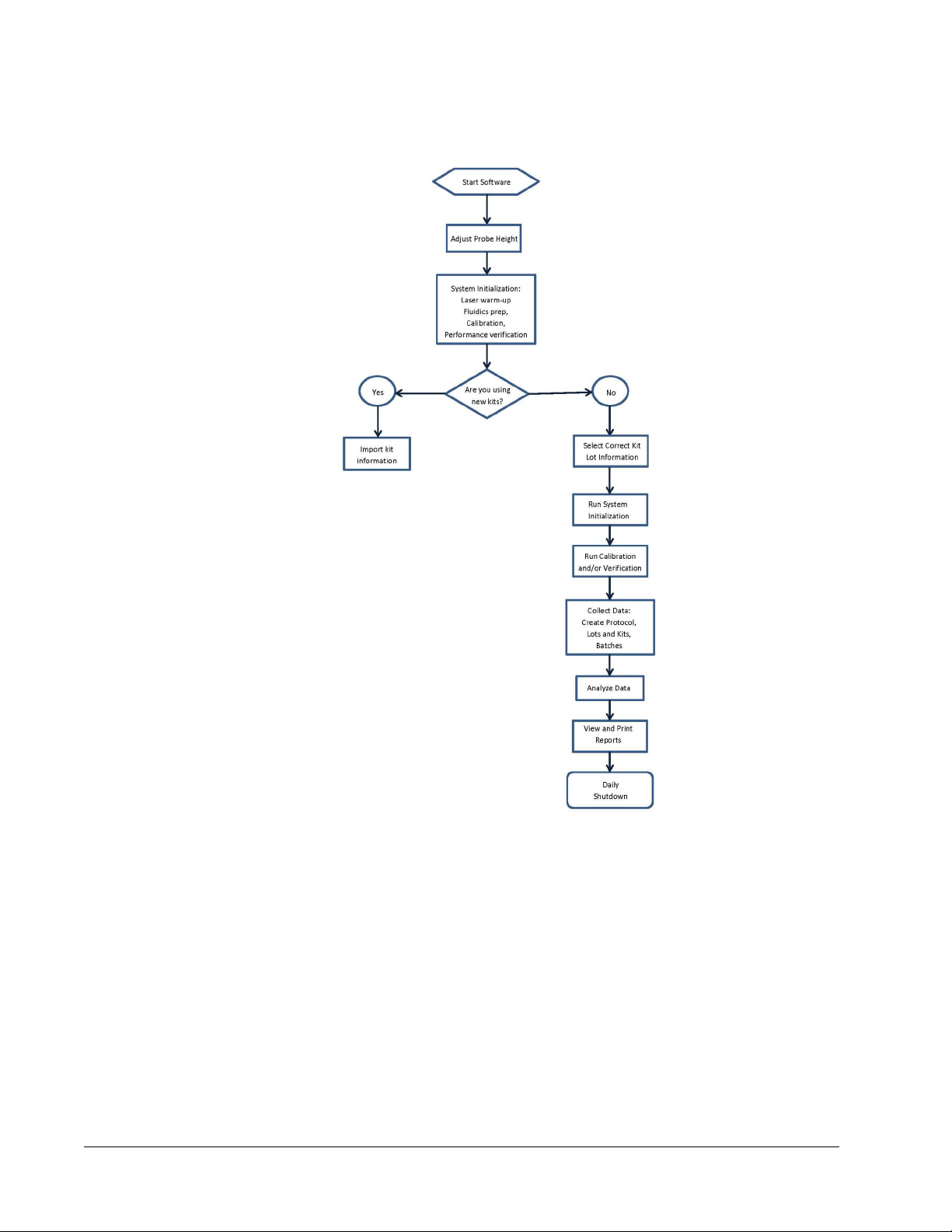
Common Daily Activities
This flowchart illustrates the flow of common daily tasks. For more information about any
task, see the Luminex® FLEXMAP 3D® Installation and Hardware User Manual or the
xPONENT® for FLEXMAP 3D®Software User Manual .
1
Page 6
Software Overview
xPONENT® software is organized into a series of pages. As you click each page, applicable
tabs open on the left-hand side of the window.
xPONENT® opens to the Home page. You can access most tasks from the Home page.
xPONENT® includes the following pages:
Home - Access most commonly used features
Samples - Import or enter sample data (optional)
Batches - Set up batches
xPONENT™ for FLEXMAP 3D
2
®
Page 7

Results - Analyze previously acquired batches; view current and saved reports
Protocols - Displays protocols, Stds & Ctrls, and Lot information.
Maintenance - Calibrate, verify, and maintain the application
Admin - Perform administrative tasks
Log Off - Log out of software
Help - Access help file
System Monitor
The System Monitor is displayed at the bottom of all xPONENT® windows. It displays the
physical state of the Luminex® system. Values are reported directly from the Luminex
system.
1 System Status button 2 Connection Status 3 Check Cal/Ver Ok
4 Command Display 5 Progress Bar and buttons 6 Stop button
7 Pause button 8 Eject button 9 Delta Cal Temp Status
10 Sheath Pressure 11 XY Status 12 Laser Status
13 Region Event Status 14 Total Events Status 15 Warm Up button
®
3
Page 8

System Status Button - This button has two functions: When clicked, it opens the system
log. It also displays the current status of the system. If there are no warnings or errors, the
System Status button is green with a check mark. If there is a warning, out of calibration
condition, or other important user notification, the button is yellow with an exclamation point.
Connection Display - Displays the connection status.
Cal/Ver Ok - This will be lit up if the calibrations and verifications are connected. When you
click the Cal/Ver button, it takes you to Maintenance > System Setup.
Command Display - Displays the following:
• The command currently running.
• The system state (i.e. running, idle, etc.).
• Date and time.
Progress - Displays a bar graph showing the progress of the current command or routine; if
the command or routine is finished, it displays a full progress bar and the command status as
Complete.
Pause - Pauses the system after the current command completes. Pause does not stop the
system in the middle of running a command. You cannot run another command while the
system is paused. Pause the system before stopping it so that it will finish the current
command, store the pending batch and then resume exactly where it left off.
Stop - Stops the system, regardless of command status. Use this only if it does not matter
whether the data from the current well is lost.
Eject - Ejects the plate. Once the plate is ejected, the Eject button changes to Retract.
Retract retracts the plate, and the Retract button changes back to Eject.
Delta Cal Temp - Displays the difference in temperature in degrees Celsius between the
current reading and the reading when the system was calibrated. If the temperature is out of
tolerance, this shows a high or low arrow. When clicked, it opens the Auto Maint tab.
Sheath Pressure - Displays the sheath pressure in psi. A high or low arrow is displayed if the
pressure is trending up or down versus the calibration pressure it turns yellow. When clicked,
it opens the System Info tab.
XY Status - Displays the current location of the command and the temperature of the plate
heating block in degrees Celsius. When clicked, it opens the Probe & Heater tab.
Laser Status - Displays the laser status, including the time remaining until you must warm
up the laser again. The Laser status box is blue. The button turns yellow when the lasers are
turned off and about ten minutes before they turn off. Clicking the Warm Up button restarts
the active clock for the laser.
Region Events Status - Displays the number of bead events detected per second that are
classified in a region.
Total Events Status - Displays the number of total events detected per second.
Warm Up Button - Starts or schedules a warmup.
Initial Startup
When you turn on the system for the first time, perform the following procedures:
1. Adjusting the Sample Probe Height
2. System Initialization
xPONENT™ for FLEXMAP 3D
4
®
Page 9

Adjusting the Sample Probe Height
Adjust the sample probe height to ensure that the probe drops far enough into the well to
acquire sample.
NOTE: Ensure that there is no liquid in the wells or reservoirs before
adjusting the sample probe height.
NOTE: When you adjust and save the probe height settings for all three
areas under a plate name, all areas retain the adjustment.
WARNING: Correct sample probe height is critical to successful sample
acquisition and calibration. Problems with the sample probe
height can lead to fluid leaks and inhibit sample acquisition.
1. On the Home page, click Probe and Heater under Daily Activities. The Probe &
Heater tab opens.
2. Select a plate in the Plate Type list.
• 96-well and 384-well Hard Bottom Plates - No disk is required. Ensure that the well
location is selected on the plate image. Use well D6 for the 96-well plate and well H12
for the 384-well plate (a green pin marks the location). To change the well location,
click on the desired well in the plate image.
• 96-well Filter or Mylar Bottom Plate - Place one (5.08) alignment disk into a well.
Ensure that the well location is selected on the plate image. Luminex® recommends
using well D6 for 96-well plates.
• 384-well Filter or Mylar Plate - Use the Probe Height Adjustment Tool (not supplied).
NOTE: You can order the Probe Height Adjustment Tool (P/N CN-0298-01)
at http://www.luminexcorp.com/Products/ORDERING-
INFORMATION
3. Verify that the microtiter is not warped. Warped plates can lead to incorrect probe height
adjustment.
4. Click Eject to eject the plate carrier.
NOTE: If using a strip-well plate, ensure that a strip is present in the
selected well location, prior to calibration.
5. Place the plate on the plate holder with A1 in the top left corner. Place the off-plate
reagent block on the plate carrier. Place a well-strip (provided with the Calibration and
the Performance Verification kits) in column S1 of the block.
NOTE: Make sure there is no liquid in the plate or the off plate reagent
block.
6. Click Retract to retract the plate carrier.
5
Page 10

7. Type a name for the plate in the Plate Name box, or select a saved plate from the Plate
Name list.
NOTE: If a saved plate is selected the results of the new calibration will
override the previous calibration.
8. In the Plate section, click D6 for the 96-well plate. Click H12 for the 384-well plate.
9. In the Reservoir section, click RB1.
10. In the Strip-Wells section, click SD1.
11. Click Auto Adjust Height. The probe automatically adjusts itself and saves it to the plate
you selected.
NOTE: The probe height is automatically set to 0.49 mm. The probe
automatically adjusts this distance from the bottom of the plate or
calibration disks.
NOTE: When you adjust and save the probe height settings for all three
WARNING: Correct sample probe height is critical to successful sample
CAUTION: Ensure that the probe height is set correctly before calibrating
xPONENT™ for FLEXMAP 3D
6
under a plate name, all areas retain the adjustment.
acquisition and calibration. Problems with the sample probe can
lead to fluid leaks and inhibit sample acquisition.
the system.
®
Page 11

Revive After Storage Routine
NOTE: The Revive After Storage routine is necessary when the system
has been idle for more than a week.
After you have adjusted the sample probe height, run the Revive After Storage (Luminex)
routine.
1. Open the Maintenance page, then the Cmds & Routines tab.
2. Select Revive After Storage (Luminex) from the Routine Name drop-down list. The
Revive After Storage routine performs the following commands:
• Warmup
• Backflush (x2)
• Drain RA2 (x3)
• Alcohol Flush RB1 (x2)
• Backflush
• Wash RA1 (x3)
3. Add 70% isopropanol or 70% ethanol to reservoir RB1 on the off-plate reagent block as
indicated on the Cmds & Routines tab. Add DI Water to reservoir RA1.
NOTE: The drain reservoir (RA2) should be empty.
4. Click Run.
After the Revive After Storage routine is complete, run the System Initialization routine.
Initialize the System
xPONENT® enables you to customize system initialization using one of these three options:
• Laser warm-up, fluidics prep, calibration, performance verification
• Laser warm-up, fluidics prep, performance verification
• Warm-up fluidics prep
NOTE: Verify the system daily and calibrate weekly to check system integrity
and to ensure that calibration is still valid.
To run the system initialization routine:
1. On the Home page, click System Initialization.
2. Select the performance verification kit from the Performance Verification Kit list.
3. Select the calibration kit from the Calibration Kit list.
4. Vortex the xMAP calibrator, verification, and fluidics containers for 30 seconds to ensure
homogeneity. Do not dilute xMAP calibrator, verification, or fluidics agents.
5. Click Eject on the status bar.
6. Place the off-plate reagent block on the plate holder. Load a strip well into the block.
7
Page 12

7. Load wells with at least five drops of the Calibration, Verification, and Fluidics beads, as
indicated on the plate image and in the kit insert instructions.
NOTE: To ensure you get the necessary bead count, invert the calibrator
and verifier vials perpendicular to the plate as you add drops to the
wells. This ensures the maximum fluid drop size is dispensed into
the wells.
8. Click Retract.
9. Click Run.
Initialize the System
xPONENT® enables you to customize system initialization using one of these three options:
• Laser warm-up, fluidics prep, calibration, performance verification
• Laser warm-up, fluidics prep, performance verification
• Warm-up fluidics prep
NOTE: Verify the system daily and calibrate weekly to check system integrity
and to ensure that calibration is still valid.
To run the system initialization routine:
1. On the Home page, click System Initialization.
2. Select the performance verification kit from the Performance Verification Kit list.
3. Select the calibration kit from the Calibration Kit list.
xPONENT™ for FLEXMAP 3D
8
®
Page 13

4. Vortex the xMAP calibrator, verification, and fluidics containers for 30 seconds to ensure
homogeneity. Do not dilute xMAP calibrator, verification, or fluidics agents.
5. Click Eject on the status bar.
6. Place the off-plate reagent block on the plate holder. Load a strip well into the block.
7. Load wells with at least five drops of the Calibration, Verification, and Fluidics beads, as
indicated on the plate image and in the kit insert instructions.
NOTE: To ensure you get the necessary bead count, invert the calibrator
and verifier vials perpendicular to the plate as you add drops to the
wells. This ensures the maximum fluid drop size is dispensed into
the wells.
8. Click Retract.
9. Click Run.
Run, Save, and Print Reports
xPONENT® can provide information in six different report types:
• Batch
• Protocol
• Calibration and Verification
• Performance Verification
• System Log
• Advanced (User)
It can also format your batch or multibatch results in a variety of export formats.
9
Page 14

To run, print, and/or save a report:
1. Open the Results page.
2. Click the Reports tab.
3. In the Report drop-down list, select the report that you want to view.
4. In the Type drop-down list, select the type of report you want to view.
NOTE: Select dates if applicable.
5. Select the item for which you want to generate the report. If you are creating a Batch
Report, select the analytes to include in the report.
6. Click Generate.
7. Click Print to print the report, or Save to save the report as a PDF file.
Create a Protocol
You can create protocols with four types of analysis:
Quantitative - Analyzes unknown data generated with a standard curve.
Qualitative - Analyzes unknown data generated with cutoff ranges based on one standard.
Allele Call - Analyzes data generated as either heterozygotes or homozygotes, based on
specific cutoff ratios.
None - Used when analysis of the data will be carried out in another program. (xPONENT
reports are unavailable for data acquired with a protocol of type “none”.)
xPONENT™ for FLEXMAP 3D
10
®
®
Page 15

You can create each quantitative, qualitative, and allele call protocols using one product
composed of a definable number of standards and controls.
There are three steps to creating a protocol. All three are accessible from the Protocols
page, Protocols tab. The three steps are:
• Define settings.
• Select the analysis type.
• Define the plate layout.
To create a protocol:
1. Open the Protocols page.
2. Click Create New Protocol. The Settings tab opens.
3. Type the protocol name, version, and manufacturer.
4. Type the following information in the Acquisition Settings panel:
• Sample volume (10-200μL)
• XY heater temperature (35-60°C)
• Timeout (1-250 seconds)
• Bead Type
• Plate name
• DD gating
• Reporter Gain
5. Select the analysis type (Qualitative, Quantitative, Allele Call, or None), and enter the
number of standards and controls.
11
Page 16

6. Select Fit of all Standards or Mean of Replicates.
7. Select Analyze results while acquiring samples if you want to view real-time analysis.
8. Click Next to open the Select Analytes tab. Select analytes by clicking the bead
number. The table allows you to name the analyte and to select the analysis type, the
units to be measured, and the count.
9. Click Change to change the analysis settings.
10. Click Next. The Plate Layout tab opens.
xPONENT™ for FLEXMAP 3D
12
®
Page 17

11. Add standards, controls, unknowns, and maintenance steps to the plate layout.
12. Click Save to save the protocol.
Creating a Kit
To create a kit:
1. Open the Protocols page, then open the Protocols tab.
2. Select the protocol that you want to use for the kit, then click New Std/Ctrl. The Std/Ctrl
Details tab opens.
3. Type the name of the kit in the Name box, the lot number in the Std/Ctrl Kit Lot# box,
the expiration date using MM/DD/YYYY format in the Expiration box, and the
manufacturer in the Manufacturer box.
4. Click Apply Std Lot if you want to apply a standard lot. The Select Lot dialog box
opens. Click a lot and select OK.
5. Click Apply Ctrl Lot to apply a control lot. The Select Lot dialog box opens. Select a lot
and click OK.
6. Alternatively, type the appropriate information in the Assay Standard Information and
Assay Control Information sections. The number of standards, controls, or both in
these sections is defined in the protocol. If your batch uses controls, select Expected,
Low or High from the Show Value options. Use the Apply Values arrows to apply
values down or across the range of analytes.
7. Click Save.
13
Page 18

Create a Batch
There are three batch creation options:
• Create a New Batch from an Existing Protocol (uses a protocol; described in this
section).
• Create a New Batch from a New Protocol
• Create a New Multi-batch (runs multiple batches at one time).
To create a new batch from an existing protocol:
1. Open the Batches page.
2. Click Create a New Batch from an Existing Protocol.
3. Type the batch name in the Batch Name box.
4. Type a description of the batch in the Enter Optional Description box.
5. Click the protocol you want to use in the Select a Protocol list. If the protocol you select
uses standards and/or controls, the active reagents are shown on the bottom of the
screen. Verify that these are the correct standards and controls.
6. Click Next.
• If the protocol you selected uses standards and controls, the Stds & Ctrls tab opens.
View the details of the active reagents and verify that they are correct; apply different
assay standards and controls, or manually enter new information. Click Next. The
Plate Layout tab opens. Confirm that the plate layout conforms to your specific assay
instructions.
• If the protocol you selected does not use standards and/or controls, the Plate Layout
tab opens. Confirm that the plate layout conforms to your specific assay instructions.
Continue with step 6.
7. On the Plate Layout tab, add samples to the plate layout if needed.
8. Click Run Batch to begin batch acquisition, or click Save to save the batch information to
the Pending Batch list, to be run at a later time.
NOTE: If the batch spans more than one plate, the tray ejects automatically
View Batches
You can observe and analyze current and previously run batches on the Results page.
To view batch data:
1. Open the Results page.
xPONENT™ for FLEXMAP 3D
14
when all defined wells have been acquired. A dialog box prompts
you to insert the next plate.
®
Page 19

2. Select the Current Batch or Saved Batches tab.
3. If you want to open a saved batch, highlight the batch and click Open.
Shut Down the Instrument
Run the daily shutdown routine to prevent clogs and crystallization of salt in the sample
probe. Clogs and crystallization of salt in the sample probe may cause problems with
calibration, verification, and data acquisition; they may also cause sample splashing. Shut
down the system properly to ensure system integrity.
1. On the Home page, click Shutdown. The Auto Maint tab opens, with System
Shutdown selected.
2. Fill the labelled area of the off-plate reagent block (RB2) with a 10-20% household
bleach and water solution.
3. Add deionized water to the labelled area of the off-plate reagent block (RA1).
4. Click Run.
Technical Support
On the Web
For more information, visit the Luminex FAQ page at http://www.luminexcorp.com/support/.
You can access the Technical Support website using a user name and password at https://
esupport.luminexcorp.com/OA_HTML/jtflogin.jsp.
15
Page 20

By Phone Inside the U.S. and Canada
Contact Luminex Technical support at:
• Toll Free: 1-877-785-BEAD (-2323)
• Fax: 512-219-5114
By Phone Outside the U.S. and Canada
Contact Luminex Technical support at:
• International Toll Free: +800 2939 4959
• Direct Phone: +1 512-381-4397
• Fax: +1 512-219-5114
Email
Email questions to support@luminexcorp.com.
xPONENT™ for FLEXMAP 3D
16
®
 Loading...