


944E-42
Table of contents
 Loading...
Operation & Safety
An Oshkosh Corporation Company
Manual
Original Instructions
Keep this manual with machine at all times.
Models
644E-42
&
944E-42
S/N 0160037794 & After
31200354
Revised
September 19, 2011

CALIFORNIA PROPOSITION 65
BATTERY WARNING
Battery posts,
terminals and related
accessories contain
lead and lead compounds,
chemical known to the
State of California
to cause cancer and
reproductive harm.
WASH HANDS
AFTER HANDLING!
CALIFORNIA PROPOSITION 65
EXHAUST WARNING
Diesel Engine exhaust and
some of its constituents
are known to the State of
California to cause cancer,
birth defects and other
reproductive harm.

Revision Log
Revision Log
March 18, 2009 - A - Original Issue of Manual
April 23, 2009 - B - Revised page 9-2.
December 21, 2010 - C - Revised pages 7-13, 9-2, 9-3 & 9-5.
September 19, 2011 - D - Revised covers and pages b, d, 1-5, 1-6, 1-9, 2-3, 2-6, 2-
7, 2-8, 2-11, 2-13, 3-1, 3-4, 3-5, 3-6, 3-7, 4-3, 4-6, 4-9, 4-10, 5-2, 5-15, 5-16, 5-18,
5-20, 5-21, 5-22, 5-24, 5-26, 5-28, 5-30, 5-32, 6-1, 7-3, 7-4, 7-5, 7-9, 7-10, 7-11,
7-12, 7-13, 7-17, 7-18, 7-19 , 7-20, 7-22, 7-23, 9-1 & 9-2.
REVISION LOG
a31200354

Read This First
Read This First
This manual is a very important tool! Keep it with the machine at all times.
The purpose of this manual is to provide owners, users, operators, lessors, and
lessees with the precautions and operating procedures essential for the safe and
proper machine operation for its intended purpose.
Due to continuous product improvements, JLG Industries, Inc. reserves the right to
make specification changes without prior notification. Contact JLG Industries, Inc.
for updated information.
Operator Qualifications
The operator of the machine must not operate the machine until this manual has
been read, training is accomplished and operation of the machine has been
completed under the supervision of an experienced and qualified operator.
Operation within the U.S.A. requires training per OSHA 1910.178.
Operators of this equipment must possess a valid, applicable driver’s license, be in
good physical and mental condition, have normal reflexes and reaction time, good
vision and depth perception and normal hearing. Operator must not be using
medication which could impair abilities nor be under the influence of alcohol or any
other intoxicant during the work shift.
In addition, the operator must read, understand and comply with instructions
contained in the following material furnished with the telehandler:
• This Operation & Safety Manual
• Telehandler Safety Manual (ANSI only)
• All instructional decals and plates
• Any optional equipment instructions furnished
The operator must also read, understand and comply with all applicable Employer,
Industry and Governmental rules, standards and re gulations.
Modifications
Any modification to this machine must be approved by JLG.
b 31200354

Read This First
This product must comply with all safety related bulletins. Contact JLG Industries,
Inc. or the local authorized JLG representative for information regarding safetyrelated bulletins which may have been issued for this product.
JLG Industries, Inc. sends safety related bulletins to the owner of record of this
machine. Contact JLG Industries, Inc. to ensure that the current owner records are
updated and accurate.
JLG Industries, Inc. must be notified immediately in all instances where JLG
products have been involved in an accident involving bodily injury or death of
personnel or when damage has occurred to personal property or the JLG product.
FOR:
• Accident Reporting and Product Safety Publications
• Current Owner Updates
• Questions Regarding Product Applications and Safety
• Standards and Regulations Compliance Information
• Questions Regarding Product Modifications
CONTACT:
Product Safety and Reliability Department
JLG Industries, Inc.
13224 Fountainhead Plaza
Hagerstown, MD 21742
USA
or Your Local JLG Office
(Addresses on back cover)
In USA:
Toll Free: 1-877-JLG-SAFE (1-877-554-7233)
Outside USA:
Phone: +1-717-485-6591
E-mail:
ProductSafety@JLG.com
c31200354

Read This First
Other Publications Available
Service Manual
Before S/N 0160041827 excluding 0160041630 ..................................8990461
S/N 0160041827 & After including 0160041630..................................31200355
Illustrated Parts Manual...............................................................................8990462
Note: The following standards may be referenced in this manual:
ANSI is compliant to ANSI/ITSDF B56.6
AUS is compliant to AS 1418.19
CE is compliant to EN1459
Refer to the machine Serial Number Plate to identify the applicable compliance
standard.
d 31200354

Table of Contents
TABLE OF CONTENTS
Revision Log
Read This First
Operator Qualifications ......................................................b
Modifications......................................................................b
Other Publications Available ..............................................d
Table of Contents
Section 1 - General Safety Practices
1.1 Hazard Classification System..............................................1-1
Safety Alert System and Safety Signal Words................1-1
1.2 General Precautions............................................................1-1
1.3 Operation Safety..................................................................1-2
Electrical Hazards...........................................................1-2
Tip Over Hazard..............................................................1-3
Travel Hazard .................................................................1-6
Load Falling Hazard........................................................1-7
Lifting Personnel .............................................................1-8
Driving Hazards on Slopes .............................................1-9
Pinch Points and Crush Hazards ..................................1-10
Fall Hazard....................................................................1-12
Chemical Hazards.........................................................1-13
Table of Contents
Section 2 - Pre-Operation and Inspection
2.1 Pre-Operation Check and Inspection...................................2-1
2.2 Safety Decals............. ... ... ... .... ...................................... .... ...2- 3
Before S/N 0160041827 excluding 0160041630 ............2-3
S/N 0160041827 & After including 0160041630.............2-6
2.3 Walk-Around Inspection.....................................................2-10
2.4 Warm-Up and Operational Checks....................................2-12
Warm-Up Check ...........................................................2-12
Operational Check ............................................. ... ... .... .2-1 2
2.5 Operator Cab.....................................................................2-13
2.6 Windows ............................................................................2-14
Cab Door Window (if equipped)....................................2-14
Section 3 - Controls and Indicators
3.1 General................................................................................3-1
3.2 Controls ...............................................................................3-2
Instrument Panel.............................................................3-4
Dash Panel .....................................................................3-6
Ignition ............................................................................3-8
Park Brake ......................................................................3-9
i31200354

Table of Contents
Parking Procedure.......................................................... 3-9
Transmission Control Lever.......................................... 3-10
Front Joystick ............................................................... 3-12
Middle Joystick............................................................. 3-13
Single Joystick (if equipped).........................................3-14
Frame Level Joystick...................... ... .... ... .................... 3-16
Accessory Control Lever (if equipped) ......................... 3-17
3.3 Steer Modes........................................... .... ....................... 3-18
Steer Mode Change .................................... ................. 3-18
3.4 Stabil-Trak™ System ...................................................... 3-19
3.5 Operator Seat.................................................................... 3-20
Adjustments..................................................................3-20
Seat Belt....................................................................... 3-21
3.6 Indicators........................................................................... 3-22
Boom Angle and Extension .......................................... 3-22
Transfer Carriage Extension........ ... ... .... ....................... 3-22
Section 4 - Operation
4.1 Engine ................................................................................. 4-1
Starting the Engine......................................................... 4-1
Cold Weather Starting Aids ............................................ 4-2
Battery Boosted Starting................................................. 4-3
Normal Engine Operation............................................... 4-4
Shut-Down Procedure ....................................................4-4
4.2 Operating with a Non-Suspended Load .............................. 4-5
Lift Load Safely............................ ... ... .... ......................... 4-5
Picking Up a Load ....................................... ... ... .... ... ...... 4-5
Transporting a Load .................................... ... ................ 4-6
Leveling Procedure......................................................... 4-6
Placing a Load................................................................ 4-7
Disengaging a Load........................................................ 4-7
4.3 Operating with a Suspended Load...................................... 4-8
Lift Load Safely............................ ... ... .... ......................... 4-8
Picking Up a Suspended Load ....................................... 4-8
Transporting a Suspended Load .................................... 4-9
Leveling Procedure......................................................... 4-9
Placing a Suspended Load............. ... .... ... .................... 4-10
Disengaging a Suspended Load .................................. 4-10
4.4 Loading and Securing for Transport.................................. 4-11
Tiedown........................................................................ 4-11
Lifting............................................................................4-12
ii 31200354

Section 5 - Attachments
5.1 Approved Attachments ........................................................5-1
5.2 Unapproved Attachments ....................................................5-1
5.3 JLG Supplied Attachments ..................................................5-2
5.4 Telehandler/Attachment/Fork Capacity................................5-4
5.5 Use of the Capa cit y Cha rt............................................. .... ...5- 5
Capacity Indicator Locations................................. ... .... ...5-5
Sample Capacity Chart...................................................5-6
Example..........................................................................5-8
5.6 Attachment Installation ......................................................5-10
Hydraulic Operated Attachment................................... .5-12
5.7 Adjusting/Moving Forks......................................................5-13
5.8 Attachment Operation........................................................5-14
Carriage w/Forks...........................................................5-15
Side Tilt Carriage ..........................................................5-16
Swing Carriage .............................................................5-18
Dual Fork Positioning Carriage.......... ... ... .....................5-20
Mast Carriage .................... ... ... ... .... ... ...........................5-22
Fork Mounted Hook ................. ... .... ... ... ... ... ..................5-24
Truss Boom...................................................................5-26
Bucket...........................................................................5-28
Grapple Bucket .............................................................5-30
Personnel Work Platform..............................................5-32
Table of Contents
Section 6 - Emergency Procedures
6.1 Towing a Disabled Product..................................................6-1
Moving Short Distances..................................................6-1
Moving Longer Distances ...............................................6-1
6.2 Emergency Lowering of Boom.............................................6-2
6.3 Emergency Exit from Enclosed Cab ....................................6-2
Section 7 - Lubrication and Maintenance
7.1 Introduction..........................................................................7-1
Clothing and Safety Gear................................ ... .............7-1
7.2 General Maintenance Instructions .......................................7-2
7.3 Service and Maintenance Schedule ....................................7-3
10 & 50 Hour Maintenance Schedule .............................7-3
1st 100, 250 & 1st 500 Hour Maintenance Schedule......7-4
500, 1000 & 2000 Hour Maintenance Schedule .............7-5
7.4 Lubrication Schedules .........................................................7-6
50 Hour Lubrication Schedule.........................................7-6
iii31200354

Table of Contents
7.5 Operator Maintenance Instructions ..................................... 7-8
Fuel System....................... ... .... ...................................... 7-8
Engine Oil..................................................................... 7-10
Hydraulic Oil............ .... ... ... ....................................... ... . 7-11
Engine Cooling System ................................................ 7-12
Tires.............................................................................. 7-14
Transmission Oil...........................................................7-17
Battery.......................................................................... 7-18
Air Intake System ......................................................... 7-20
Section 8 - Additional Checks
8.1 Stabil-Trak™ ....................................................................... 8-1
Section 9 - Specifications
9.1 Product Specifications...................... ... ... ............................. 9-1
Capacities....................................................................... 9-1
Tires................................................................................ 9-3
Performance................................................................... 9-4
Dimensions..................................................................... 9-5
Index
Inspection, Maintenance and Repair Log
iv 31200354

Section 1 - General Safety Practices
DANGER
OW0010
WARNING
OW0021
CAUTION
OW0031
SECTION 1 - GENERAL SAFETY PRACTICES
1.1 HAZARD CLASSIFICATION SYSTEM Safety Alert System and Safety Signal Words
DANGER indicates an imminently hazardous situation which, if not avoided, will
result in death or serious injury.
WARNING indicates a potentially hazardous situation which, if not avoided, could
result in death or serious injury.
CAUTION indicates a potentiality hazardous situation which, if not avoided, may
result in minor or moderate injury.
1.2 GENERAL PRECAUTIONS
WARNING
Before operation, read and understand this manual. Failure to comply with the
safety precautions listed in this manual could result in machine damage, property
damage, personal injury or death.
1-131200354

Section 1 - General Safety Practices
OW0040
10 FT
(3 M)
1.3 OPERATION SAFETY Electrical Hazards
• This machine is not insulated and does not provide protection from contact or
being near electrical current.
• NEVER operate the telehandler in an area where overhead power lines,
overhead or underground cables, or other power sources may exist without
ensuring the appropriate power or utility company de-energizes the lines.
• Always check f or power lines before raising the boom.
• Follow employer, local and governmental regulations for clearance from
powerlines.
1-2 31200354
Section 1 - General Safety Practices
OW0050
OW0080
OW0100
4 FT
(1,2 M)
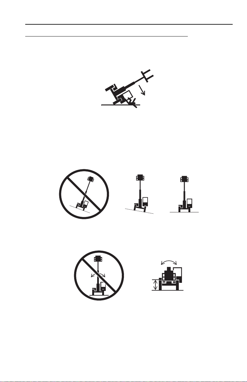
Tip Over Hazard
General
• For additional load requirements, refer to the appropriate capacity chart.
• Never use an attachment without the appropriate JLG approved capacity char t
installed on the telehandler.
• Understand how to properly use the capacity charts located in cab.
• DO NOT exceed rated lift capacity.
• Be sure that the ground conditions are able to support the machine.
• DO NOT raise boom unless frame is le v el (0 degrees), unless otherwise noted on
capacity chart.
• DO NOT level machine with boom/attachment above 4 ft (1,2 m).
(AUS - DO NOT level machine with load more than 11.8 in (300 mm) above
ground surface.)
1-331200354

Section 1 - General Safety Practices
OH2291
OH20911
OH2221
• MAINTAIN proper tire pressure at all times. If proper tire pressures are not
maintained, this machine could tip over.
• Refer to manufacturer’s specifications for proper fill ratio and pressure
requirements for tires equipped with ballast.
• Always wear the seat belt.
• Keep head, arms, hands, legs and all other body parts inside operator’s cab at all
times.
If the telehandler starts to tip over:
• DO NOT JUMP
• BRACE YOURSELF and STAY WITH THE MACHINE
• KEEP YOUR SEAT BELT FASTENED
• HOLD ON FIRMLY
• LEAN AWAY FROM THE POINT OF IMPACT
1-4 31200354
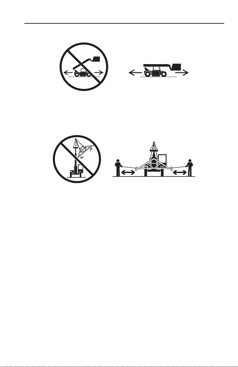
Non-Suspended Load
OW0060
OW0150
• DO NOT drive with boom raised.
Suspended Load
Section 1 - General Safety Practices
• Tether suspended loads to restrict movement.
• Weight of all rigging (slings, etc.) must be included as part of load.
• Beware of wind. Wind can cause a suspended load to swing and cause
dangerous side loads - even with tag lines.
• DO NOT attempt to use telehandler frame-leveling to compensate f or load s wing.
• Keep heavy part of load closest to attachment.
• Never drag the load; lift vertically.
When driving with a suspended load:
• Start, travel, turn and stop slowly to prevent load from swinging.
• DO NOT extend boom.
• DO NOT raise the load more than 11.8 in (300 mm) above ground surface or
the boom more than 45°.
• DO NOT exceed walking speed.
1-531200354

Section 1 - General Safety Practices
OAL2030
2-Wheel Front Steer 4-Wheel Circle Steer 4-Wheel Crab Steer
Travel Hazard
• Steering characteristics differ between steer modes. Identify the steer mode
settings of the telehandler being operated.
• DO NOT change steer modes while traveling. Steer modes must be changed
while telehandler is stationary.
• Visually verify proper wheel alignment after each steer mode change.
• Ensure that adequate clearance is provided for both rear tail swing and front fork
swing.
• Look out for and avoid other personnel, machinery and vehicles in the area. Use
a spotter if you DO NOT have a clear view.
• Before moving be sure of a clear path and sound horn.
• When driving, retract boom and keep boom/attachment as low as possible while
maintaining visibility of mirrors and maximum visibility of path of travel.
• Always look in the direction of travel.
• Always check boom clearances carefully before driving underneath overhead
obstructions. Position attachment/load to clear obstacles.
• When driving in high speed, use only front wheel steer (if steeri ng modes are
selectable).
1-6 31200354

Section 1 - General Safety Practices
OW0130
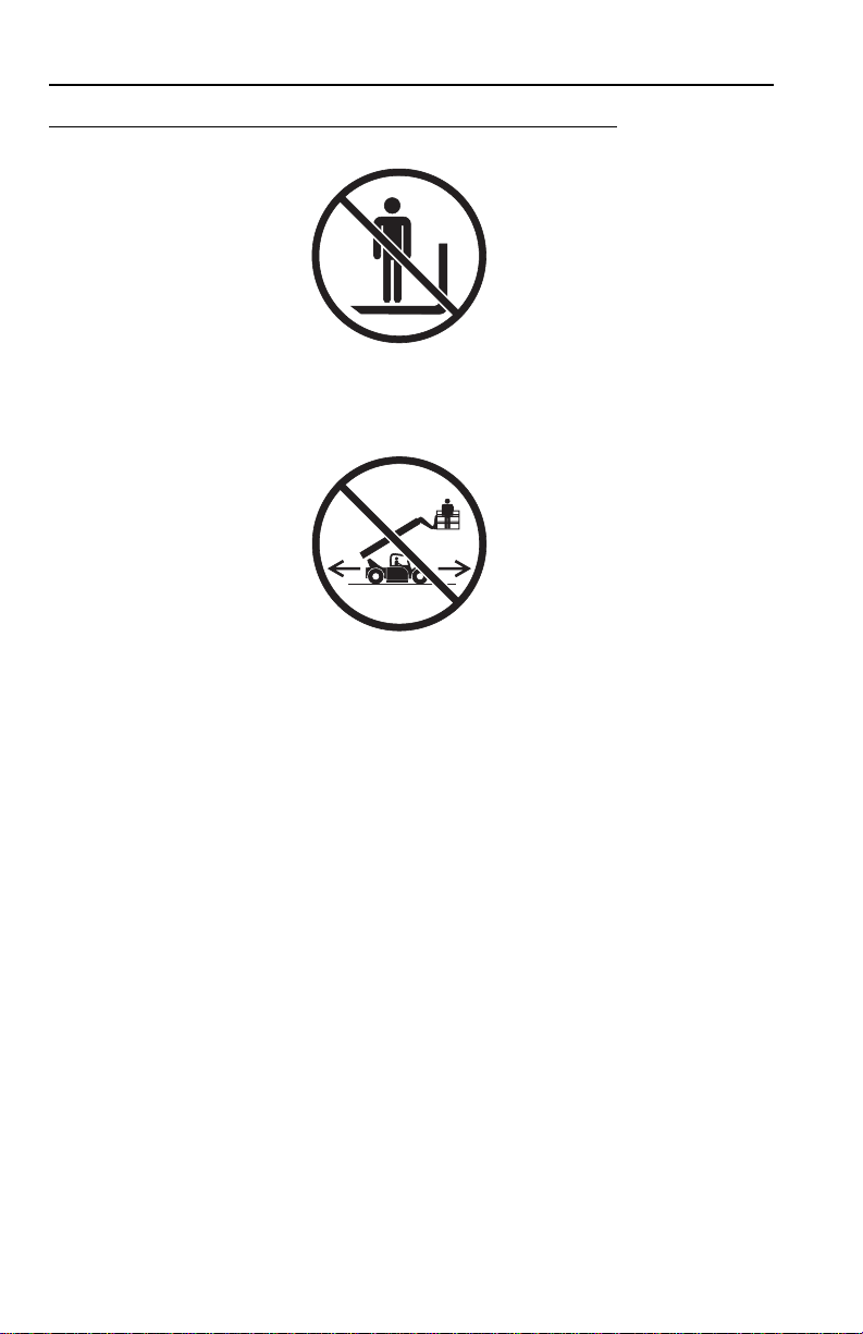
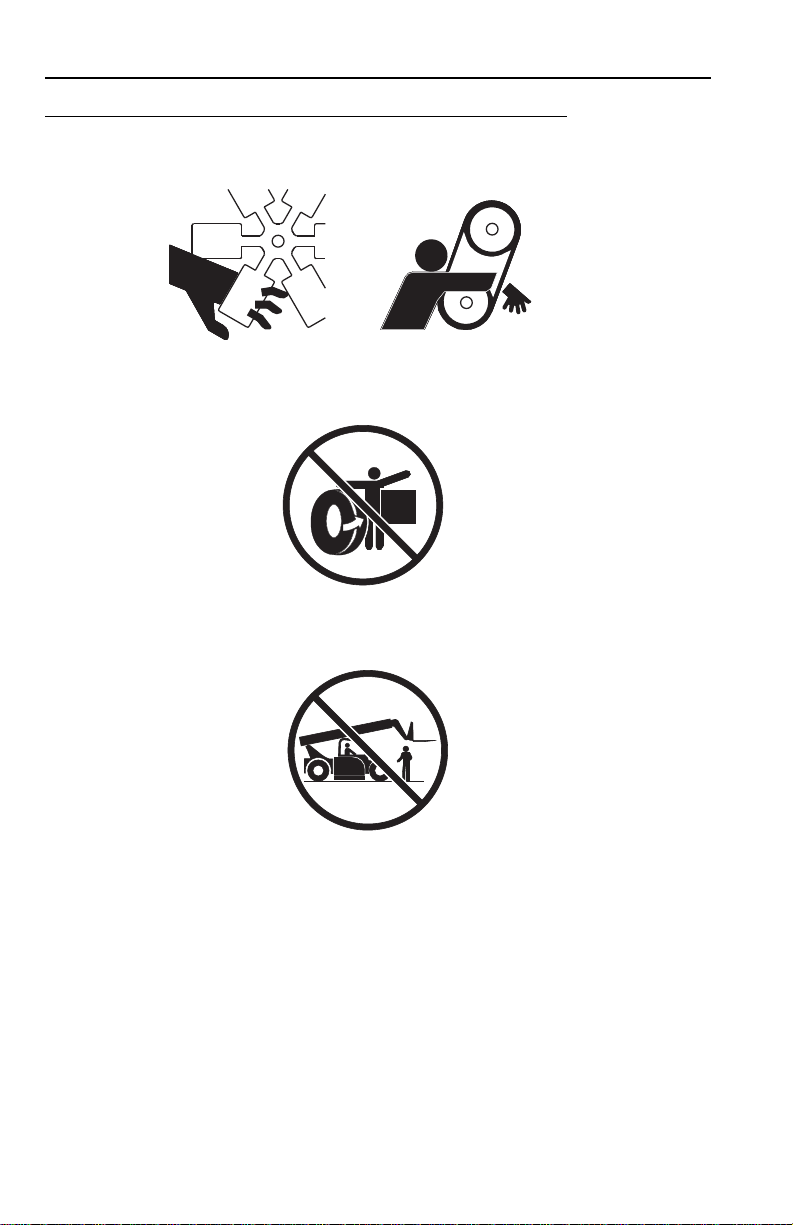
Load Falling Hazard
• Never suspend load from forks or other parts of carriage.
• DO NOT burn or drill holes in fork(s).
• Forks must be centered under load and spaced apart as far as possible.
1-731200354
Section 1 - General Safety Practices
OW0170
OW0190
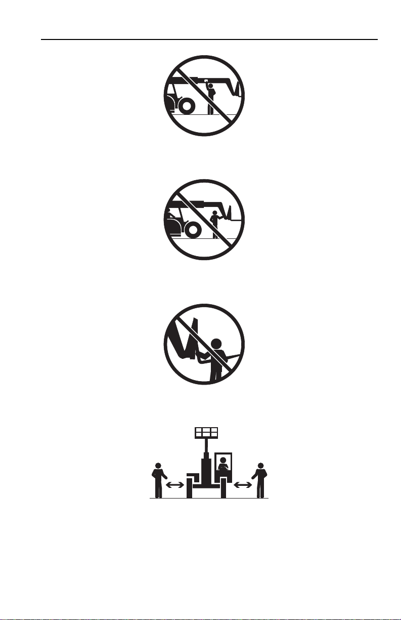
Lifting Personnel
• When lifting personnel, USE ONLY a JLG approved personnel work platform,
with proper capacity chart displayed in the cab.
• DO NOT drive machine from cab when personnel are in platform.
1-8 31200354
Section 1 - General Safety Practices
OW0200
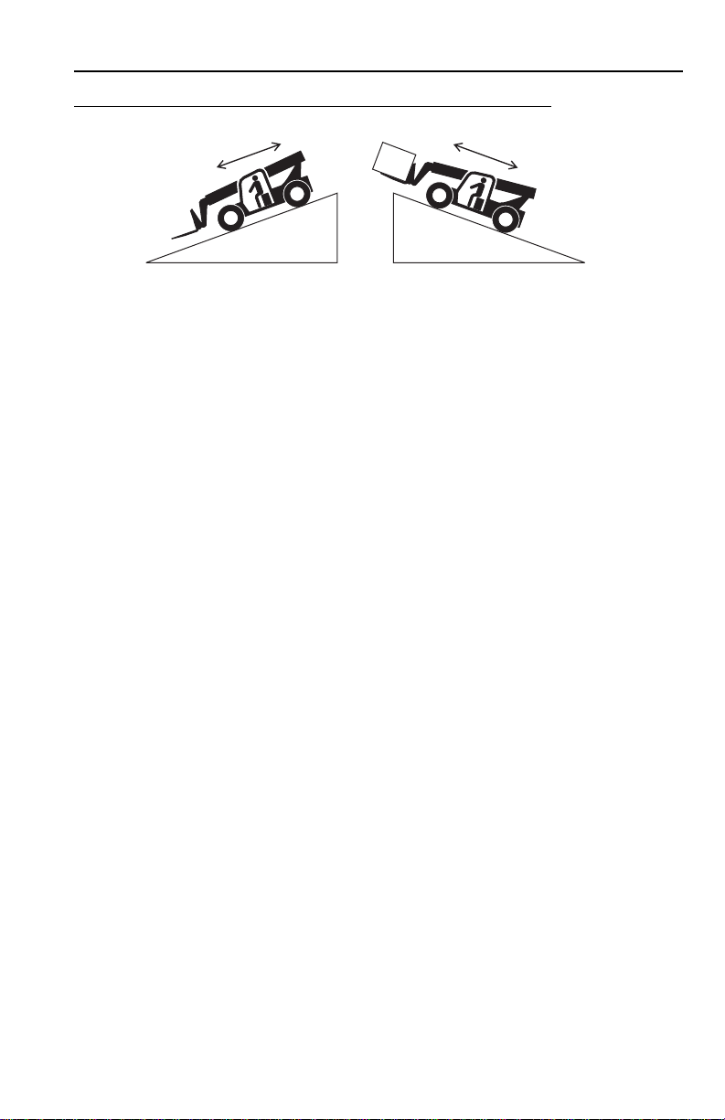
Driving Hazards on Slopes
To maintain sufficient traction and braking capabilities, travel on slopes as follows:
• When unloaded, drive with forks pointed downhill.
• When loaded, drive with the forks pointed uphill.
• For additional travel requirements, refer to the appropriate capacity chart.
• To avoid overspeeding the engine and drivetrain when driving down slopes,
downshift to a lower gear and use the service brake as necessar y to maintain a
slow speed. DO NOT shift into neutral and coast downhill.
• Avoid excessively steep slopes or unstable surfaces. To avoid tip over DO NOT
drive across excessively steep slopes under any circumstances.
• Avoid turning on a slope. Never engage “inching” or shift to “Neutral” when going
downhill.
• DO NOT park on a slope.
1-931200354
Section 1 - General Safety Practices
OW0210
OW0220
OW0230
Pinch Points and Crush Hazards
Stay clear of pinch points and rotating parts on the telehandler.
• Stay clear of moving parts while engine is running.
• Keep clear of steering tires and frame or other objects.
• Keep clear from under boom.
1-10 31200354
Section 1 - General Safety Practices
OW0240
OW0250
OW0260
OW0960
• Keep clear of boom holes.
• Keep arms and hands clear of attachment tilt cylinder.
• Keep hands and fingers clear of carriage and forks.
• Keep others away while ope rating.
1-1131200354

Section 1 - General Safety Practices
OW0280
OW0290
Fall Hazard
• Enter using the proper hand holds and steps provided. Always maintain 3-point
contact when mounting or dismounting. Never grab control levers or steering
wheel when mounting or dismounting the machine.
• DO NOT get off the machine until the shutdown procedure on page 4-5 has been
performed.
• DO NOT carry riders. Riders could fall off machine causing death or serious
injury.
1-12 31200354

Section 1 - General Safety Practices
OW0300
OW0950
Chemical Hazards
Exhaust Fumes
• DO NOT operate machine in an enclosed area without proper ventilation.
• DO NOT operate the machine in hazardous environments unless approved fo r
that purpose by JLG and site owner. Sparks from the electrical system and the
engine exhaust can cause an explosion.
• If spark arrestors are required, ensure they are in place and in good work ing
order.
Flammable Fuel
• DO NOT fill the fuel tank or service the fuel system near an open flame, sparks
or smoking materials. Engine fuel is flammable and can cause a fire and/or
explosion.
Hydraulic Fluid
• DO NOT attempt to repair or tighten any hydraulic hoses or fittings while the
engine is running or when the hydraulic system is under pressure.
• Stop engine and relieve trapped pressure. Fluid in the hydraulic system is under
enough pressure that it can penetrate the skin.
• DO NOT use your hand to check for leaks. Use a piece of cardboard or paper to
search for leaks. Wear gloves to protect han ds from spraying fluid.
1-1331200354

Section 1 - General Safety Practices
This Page Intentionally Left Blank
1-14 31200354
Section 2 - Pre-Operation and Inspection
OAH1000
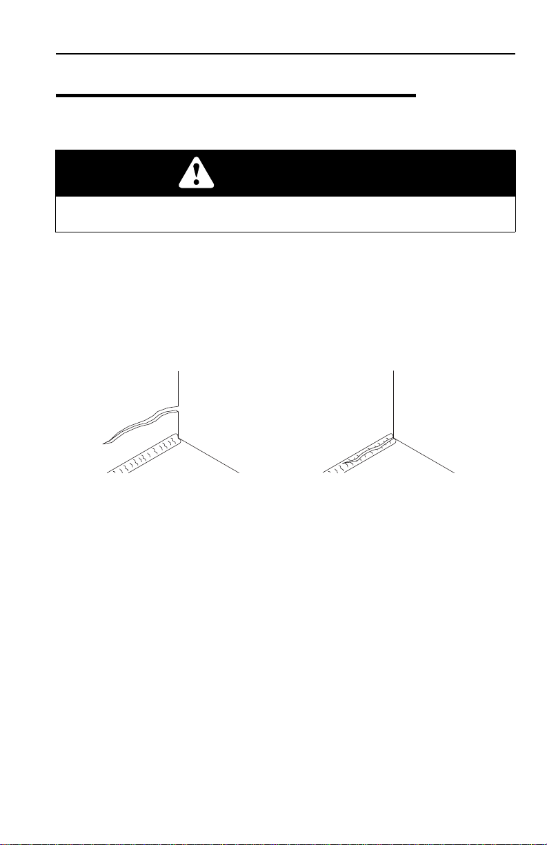
PARENT METAL CRACK WELD CRACK
SECTION 2 - PRE-OPERATION AND INSPECTION
2.1 PRE-OPERATION CHECK AND INSPECTION
Note: Complete all required maintenance before operating unit.
WARNING
FALL HAZARD. Use extreme caution when checking items beyond your normal
reach. Use an approved ladder.
The pre-operation check and inspection, performed at beginning of each work shift
or at each change of operator, should include the following:
1. Cleanliness - Check all surfaces for leakage (oil, fuel or battery fluid) or foreign
objects. Report any leakage to the proper maintenance personnel.
2. Structure - Inspect the machine structure for dents, damage, weld or parent
metal cracks or other discrepancies.
3. Safety Decals - Ensure all safety decals are legible and in place. Clean or
replace as required. See page 2-3 for details.
4. Operation and Safety Manuals - Operation & Safety Manual and AEM Safety
Manual (ANSI only) are located in cab manual holder.
5. Walk-Around Inspection - See page2-10 for details.
6. Fluid Levels - Check fluids, including fuel, hydr aulic oil, engine oil, transmission
fluid and coolant. When adding fluids, refer to Section 7 - Lubrication and
Maintenance and Section 9 - Specifications to determine proper typ e and
intervals. Before removing filler caps or fill plugs, wipe all dirt and grease away
from the ports. If dirt enters these ports, it can severely reduce component life.
7. Attachments/Accessories - Ensure correct capacity charts are installed on the
telehandler. If provided, reference the Operation & Safety Manual of each
attachment or accessory installed for specific inspection, operation and
maintenance instructions.
2-131200354

Section 2 - Pre-Operation and Inspection
8. Operational Check - Once the walk-around inspection is complete, perform a
warm-up and operational check (see page 2-12) of all systems in an area free
of overhead and ground level obstructions. See Section 3 - Controls and
Indicators for more specific operating instructions.
WARNING
If telehandler does not operate properly, immediately bring machine to a stop,
lower boom and attachment to ground and stop the engine. Determine cause and
correct before continued use.
2-2 31200354

Section 2 - Pre-Operation and Inspection
OU1781
DANGER
4108991
CONTACTING
ELECTRIC
POWER LINES
can result in
electrocution.
NEVER operate
vehicle within
10 feet (3m) of
electric power
lines.
4108991
DANGER
4110137
DO NOT raise
boom while
on a slope
unless load
is level.
VEHICLE
TIPOVER
can result
in death or
serious injury.
DO NOT
travel
with the
boom
raised.
MAINTAIN
proper tire
pressure at
all times.
4110137
4110359
4110359
DANGER
AVOID CRUSHING
if vehicle tips.
Jumping can
result in death
or serious
injury.
DO NOT JUMP.
Brace yourself.
Stay in cab.
Keep seat belt on.
1705956
1705956
0000000
RPM X 100
5
10
15
30
20
25
F
1/2
E
104
176
80
248
120
°C
°F
D
r/min
SAFETY
INSTRUCTIONS
4110361
1. Read operator's
manual before
operating.
2. Fasten
seat
belt.
3. Allow
no
riders.
4. Use a compliant
work platform to lift
or lower personnel.
4110361
WARNING
AVOID
CRUSHING,
falling off
vehicle can
cause death
or serious
injury.
1705957
ALWAYS
engage parking
brake before
dismounting
WARNING
VEHICLE
ROLLAWAY
can cause
death or
serious
injury
1705957
4110360
4110360
4110366
4110366
4110367
4110367
4110423
4110423
4110367
4110367
VIEW INSIDE CAB
DUAL JOYSTICK
CONFIGURATION
SINGLE JOYSTICK
CONFIGURATION
CAPACITY
CHARTS
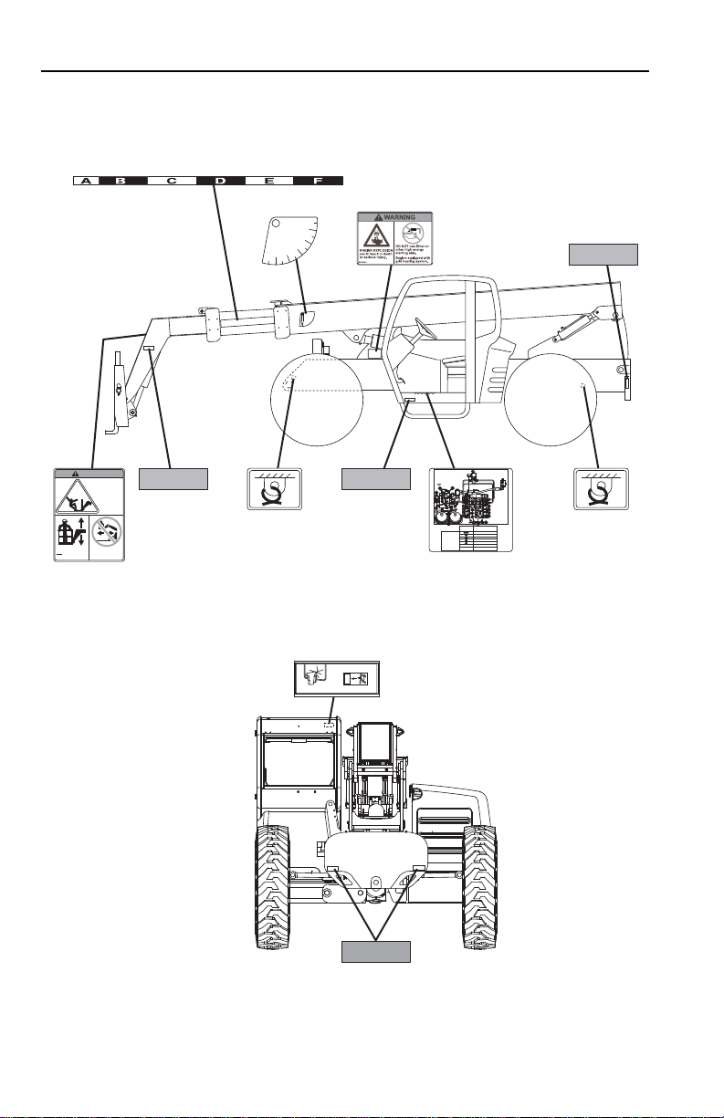
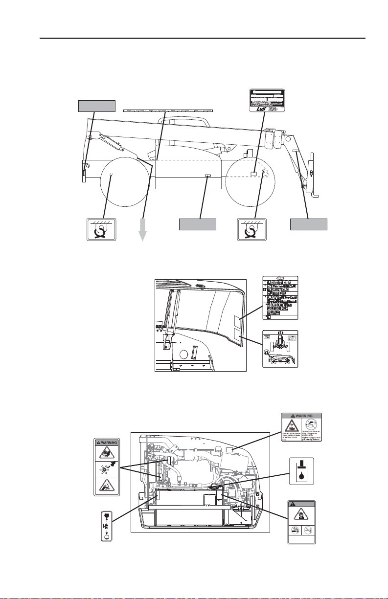
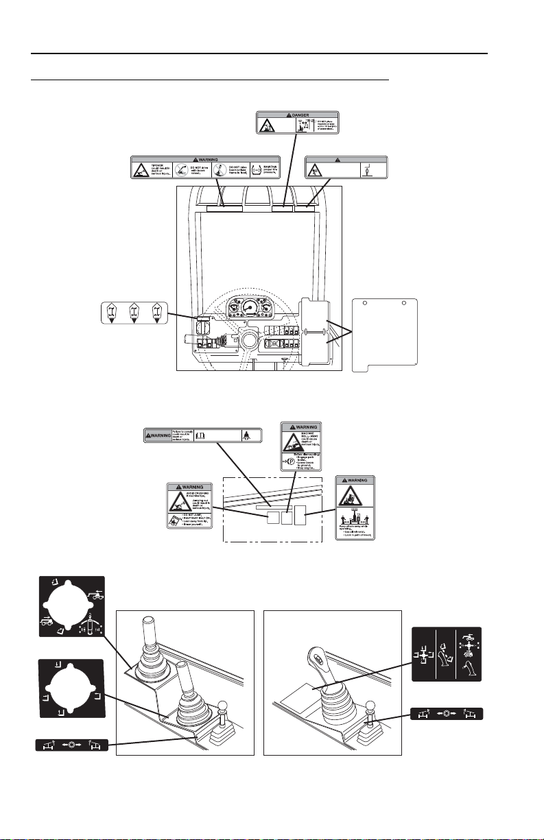
2.2 SAFETY DECALS
Ensure all DANGER, WARNING, CAUTION and instructional decals and proper
capacity charts are legible and in place. Clean and replace as required.
Before S/N 0160041827 excluding 0160041630
2-331200354
Section 2 - Pre-Operation and Inspection
OU1791
ANGUS-PALM 005413
91404299
7301379
1706300
7301380
7301380
4109801
4109801
4110392
Pressure TapFunction Tested
Location
Main Valve Pressure
Pilot Pressure
Park Brake
Pump #1
Accumulator Pressure
A Load Sense (Steering)*
B Load Sense (Implement)*
B
10
210
2
3
4
6
A
5
3
4
5
6
Refer to Hydraulic Test
Laminate or Service
Manual for proper
testing procedures.
*Consult with OQT Technical
Service Department for
additional testing information.
4110392
FALLING OFF ATTACHMENT,
can result in death or
serious injury.
DO NOT TRAVEL
with personnel in
a work platform.
4110389
Lift or lower personnel
only in a compliant
work platform.
WARNING
4110389
-10
0
10
20
30
40
50
60
7
0
8
0
4105262
4110130
7301380
4109801
4109801
2-4 31200354
OU1801
4110350
10
250
2000
1000
50
L
B
-
F
T
(
N
m
)
100
P
1001103931
4110349
2
2
4110349
1707079
1707079
-
WARNING
EXPLOSIVE GASES can
cause serious injury.
Keep sparks, flames
and lighted materials
away from batteries.
1707077
1707077
1707114
1707114
MOVING PARTS can cut.
Keep clear of fan and belts
while engine is running.
MOVING PARTS can entangle.
4110184
4110184
1706300
4109801
4109801
7301380 7301380
7301380
4109801
4109801
4110405
6
1705883
4110356
0
1
Ft
2Ft3
Ft
4
Ft
5
Ft
6
Ft
120cm
110cm 100cm 90cm 80cm 70cm 60cm 50cm 40cm 30cm 20cm 10cm130cm140cm150cm160cm170cm180cm190cm200cm
4110356
VIEW OF ENGINE COMPARTMENT
UNDERSIDE VIEW OF
ENGINE COVER
Section 2 - Pre-Operation and Inspection
2-531200354
Section 2 - Pre-Operation and Inspection
OU2440
0000000
RPM X 100
5
10
15
30
20
25
F
1/2
E
104
176
80
248
120
°C
°F
D
r/min
4110359
4110359
1706306A
1706306
1706850A
CRUSHING HAZARD
Keepothers
awaywhile
operating.
Loweringboom or falling load could
causedeath or serious injury.
WARNING
1706850
1706299A
CONTACTING
POWERLINES
willresult in death
orserious injury.
1706299
1706304A
RUN-OVER
HAZARD
couldcause
deathor
serious
injury.
1706304
1706767A
1706767
Fasten
seat
belt.
1706303A
Operatormust be trained and
mustread and understand
allcapacity charts, operator
andsafety manuals.
1706303
1706851A
1706851
4110360
4110360
4110366
4110366
4110367
4110367
4110423
4110423
4110367
4110367
VIEW INSIDE CAB
DUAL JOYSTICK
CONFIGURATION
SINGLE JOYSTICK
CONFIGURATION
CAPACITY
CHARTS
VIEW OF DECALS LOCATED INSIDE
CAB ON RIGHT HAND WALL
S/N 0160041827 & After including 0160041630
2-6 31200354
Loading...