


LH2

Operating instructions
Hydraulic Tools
Hand pump LH1 / LH2
and accessories
84129/2430-85 GB
Issue 04.2009
replaces 03.2008
(Translation of the original operating instructions)

2
Contents Page
1. Danger classes 4
2. Product safety 4
3. Proper use 7
4. Main components of the hand pump 8
5. Functional description 9
5.1 Base pump 9
5.2 Adapter blocks 9
6. Mounting of base plates and valve blocks 10
6.1 Basics for mounting base plates and valve blocks 11
6.2 Base plates 12
6.3 4/3-way valve 13
6.4 2-way distribution valve 14
6.5 Oil distributor with pressure gauge connection 15
7. Connection options for hydraulic equipment 16
7.1 Direct connection into the pump head
(only in operation with single-acting cylinders) 16
7.2 Quick-disconnect couplings 17
7.3 Screwed joint couplings 17
7.4 Direct connection into the valve block 17
7.5 Direct connection into the oil distributor block 19
8. Commissioning 20
7.6 Direct connection into the base plate 20
8.1 Unlocking the pump 21
8.2 Bleeding the pump 21
9. Operation 22
9.1 Notes for a secure operation of the hand pump 22
9.2 Hand pump (basic pump) 22
9.3 Hand pump with base plate 22
9.4 Hand pump with 4/3-way valve 23
9.5 Hand pump with 2-way distribution valve 23
9.6 Hand pump with oil distributor and pressure gauge 24
9.7 Shutdown / storage 24

3
10. Transport 24
11. Maintenance and repair 24
11.1 Basic requirements 24
11.2 Maintenance 26
11.3 Hydraulic uid change or adding hydraulic uid 27
11.4 Care 27
11.5 Repair (hand pump) 28
11.6 Repair (accessories) 34
11.7 Repair (couplings and decals) 36
12. Troubleshooting 37
13. Technical data 40
13.1 Data of the hand pumps 40
13.2 Hydraulic uid recommendation 42
13.3 Operating and storage temperature ranges 42
14. Notes 43
4
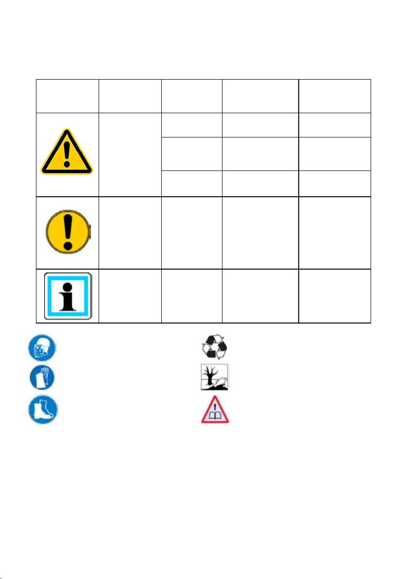
Danger classes1.
We distinguish between various categories of safety instructions. The table shown below
shows you the overview, via the assignment of symbols (pictograms) and signal words, of
the concrete danger and the possible consequences.
Pictogram
Wear helmet with face guard
Damage /
injury to
human
device
- NOTE
Key word Denition Consequences
DANGER! Immediate danger
WARNING!
CAUTION!
CAUTION!
Proper recycling
Potentially
dangerous
situation
Less dangerous
situation
Danger of damage
to device /
environment
Advice for
application and
other important /
useful information
and advice
Death or major
injury
Potential death or
major injury
Minor or slight
injury
Damage to the
equipment,
damage to the
environment,
damage to
surrounding
materials
No injury /
damage to
persons /
environment /
equipment
Wear protective gloves
Wear safety shoes
Protect the environment
Read and follow operating
instructions
Product safety2.
LUKAS products are developed and produced in order to ensure the best performance and
quality with proper use.
The safety of the operator is the most important consideration in the product design.
In addition, the operating instructions are to help in using the LUKAS products safely.
In addition to the operating instructions, all generally applicable, statutory and other
binding rules for accident prevention and for environmental protection must be heeded and
disseminated.
The device must only be operated by educated persons who are trained in safety technology,
since otherwise there is a risk of injury.
5
We advise all users before using the device to carefully read through the operating instructions
and to follow the instructions contained therein without exception.
We also recommend that you get instructed by a qualied trainer in the use of the product.
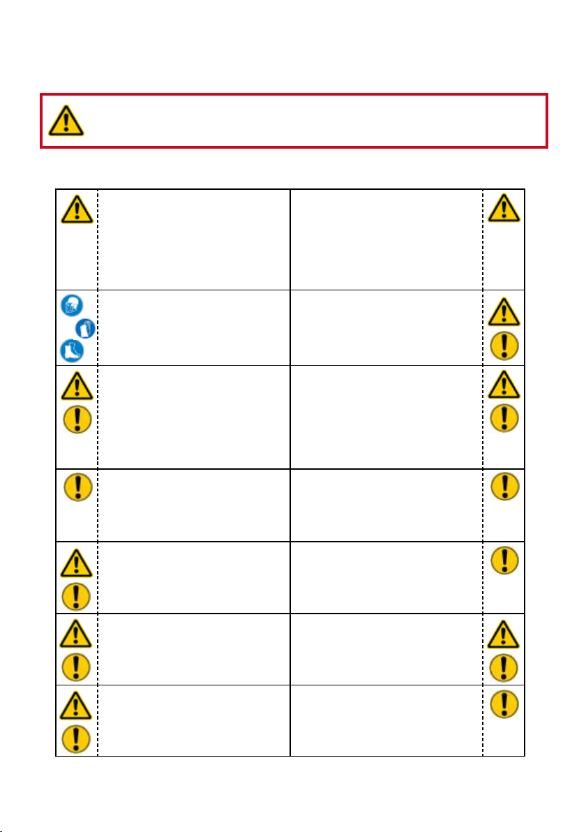
WARNING / CAUTION!
The operating instructions for the hoses, the accessories and the connected
devices must also be heeded!
Even if you have already received instruction, you should read the following safety instructions
again.
Make sure that no body parts
or clothing get between the
openly visible moving parts of
the device.
Wear protective clothing,
protective helm with visor,
safety shoes and protective
gloves.
Immediately report changes
that occur (including changes
in operating behavior) to
the appropriate persons/
departments! If necessary,
immediately shut down and
secure the device!
Check the device for visible
defects or damage before and
after use.
Working under loads is
prohibited if they are raised
exclusively with hydraulic
devices. If this work is
unavoidable, sufcient
mechanical supports are
additionally required.
In the event of malfunctions,
shut down the device
immediately and secure it. You
should have the malfunction
repaired immediately.
Heed all safety instructions
and hazard warnings on the
device and in the operating
instructions.
Make sure that all safety
covers are present on the
device and in proper working
condition.
Safety equipment must never
be disabled!
Check all lines, hoses and
screwed connections for leaks
and externally visible damages
and repair immediately!
Escaping hydraulic uid can
lead to injuries and res.
Do not make any changes
(add-ons or conversions)
on the device without the
approval of LUKAS.
All safety instructions and
hazard warnings on the device
are to be kept intact and in a
legible condition.
Any work procedure that
detracts from the safety and/
or stability of the device should
be abandoned!
The maximum permissible
operating pressure must not
be changed.
6
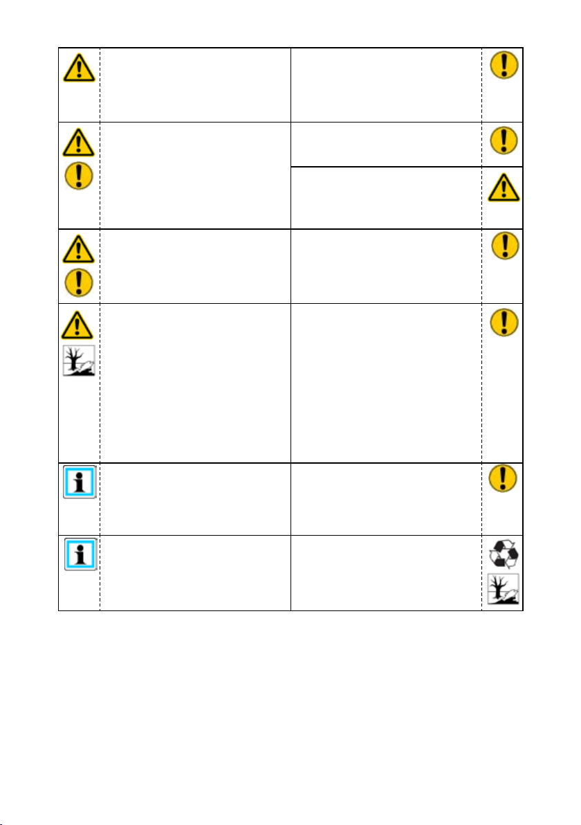
Before switching on/engaging
the device or while operating
the device, it must be ensured
that no one is endangered by
the operation of the device.
When working in the vicinity
of live components and lines,
take appropriate measures for
preventing current transfers or
high voltage ashovers to the
device.
Prevent electrostatic
discharge, which has the
possible consequence of spark
formation, when handling the
device.
The device is lled with
hydraulic uid. These hydraulic
uids can be detrimental to
health if they are swallowed
or their vapours are inhaled.
Direct contact with the skin
should be avoided for the
same reason. Also, when
handling hydraulic uids, note
that they can negatively affect
biological systems.
Make sure there is adequate
lighting while working.
Always keep these operating
instructions easily accessible
at the site where the device is
used.
Observe all intervals that
are prescribed or specied
in the operating instructions
for recurring tests and/or
inspections.
For repairs only original
LUKAS accessories and spare
parts are to be used.
Make sure that you do not
get caught in the hose loops
and trip when working with or
transporting the device.
When the hand pumps are set
up, care needs to be taken
that they are not impaired by
extremely strong temperature
changes.
When operating and/or storing
the device, make sure that the
function and the safety of the
device are not impaired by
strong external temperature
differences or that the device
is damaged. Keep in mind that
the device can also heat up
when it is continuously used.
Before transporting the device,
always check to see that the
accessories are positioned
securely to prevent the
possibility of an accident.
Make sure you properly
dispose of all removed parts,
leftover hydraulic uid, leftover
oil and packing materials.
7
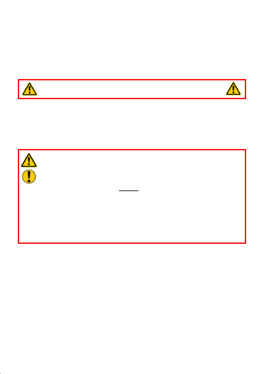
WARNING / CAUTION / ATTENTION!
The device is specied exclusively for the purpose represented in the operating
instructions (see Chapter "Proper use"). Any use that differs or goes beyond this is
considered improper. The manufacturer/supplier shall not be held liable for damages
resulting from improper use. The risk shall be borne solely by the user.
Proper use also includes heeding the operating instructions and complying with the inspection
and maintenance requirements.
Never work in a fatigued or intoxicated state!
Proper use3.
The LUKAS hand pump is used for the operation of devices of the LUKAS Hydraulic tools.
They can be used as an additional or replacement drive source along with the LUKAS
hydraulic unit (e.g. in areas at risk for explosion).
Use with equipment of other manufacturers is possible, but requires technical testing and
approval of LUKAS on a case-by-case basis.
WARNING / CAUTION / ATTENTION!
Always note the product limitations with respect to operating pressure, load limit
values and operating conditions. The operating pressure should not be higher
than the lowest maximum operating pressure of any system components.
The operating pressure should NEVER be set higher than that which is specied
in the "Technical Data" chapter. A higher setting may cause property damage
and/or injuries.
Make sure that the usable capacity of the hand pump (see chapter "Technical
Data") is sufcient for operating the connected cylinders or devices.
The required hydraulic uid operating quantity can be found in the chapter
"Technical Data" or in the operating instructions of the devices to be operated.
Accessories and spare parts for the hydraulic equipment can be obtained from your
authorised LUKAS dealer!
8
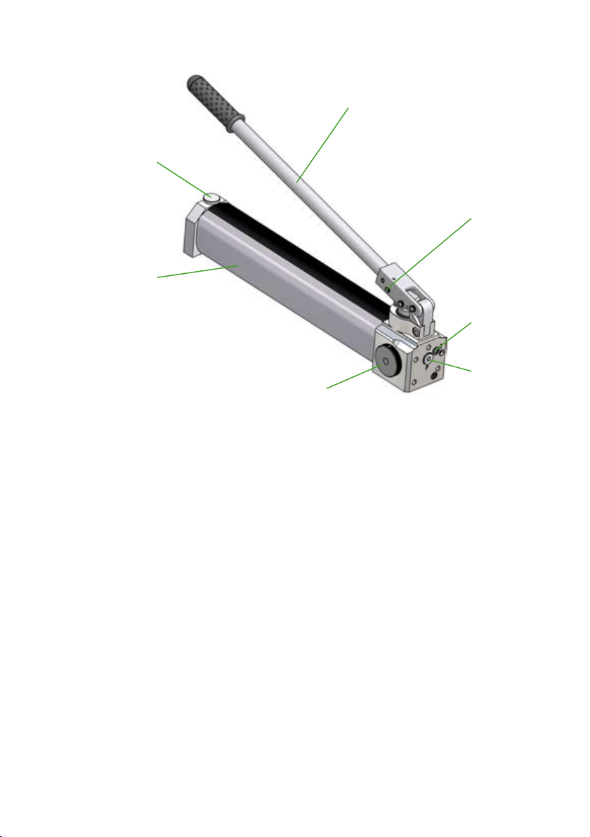
Main components of the hand pump4.
5
4
7
6
1 Hand relief valve
2 Port P
3 Return port T
4 Vent / ll cap
5 Pump lever
6 Reservoir
7 Lock
3
2
1

9
Functional description5.
5.1 Base pump
All LUKAS hand pumps of this series are two-speed, i.e. they have two operating speeds:
• A high speed in the low pressure range (LP) for fast extension of the cylinder or device
while unloaded
• A low speed in the high pressure range (HP) for controlled extension of the cylinder or
device while loaded
The switch from low pressure (LP) to high pressure (HP) is automatic at the factory setting
for changeover pressure (see chapter "Technical Data").
A pressure port "P" with a G1/4" thread and a return port "T" with an M10 thread (usually
closed) are directly available as ports on the pump.
With the basic pump it’s only possible to operate single-acting cylinders or devices.
To use other connections or double-acting cylinders or hydraulic devices, you will have to
mount adapter blocks (see chapter “adapter blocks”.
In some of the offered LUKAS hand pumps this adapter blocks are part of the shipment
and they are already mounted.
5.2 Adapter blocks
Adapter kit Ref. no. Weight
[kg]
Base plate 841297410 0,3 Add-on of a second return
Function / application
port (G1/4”) on the pump.
The base plate is a basic
requirement to mount valve
blocks and oil distributors
on the pump.
4/3-way valve 841297310 1,5 Control valve to extend
and retract double-acting
cylinders / hydraulic
devices.
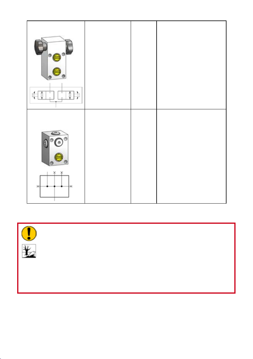
10
2-way-distribution
valve N2W
841489903 2,1 Distribution valve to divide
one oil ow into two ows.
By closing or opening the
valve screw, the partial
ows could be regulated
and harmonized.
(Base plate is a basic
requirement)
Oil distributor with
pressure gauge
connection N4M
841489905 1,4 By use of the oil distributor
one oil ow can be divided
into 5 ows. The distributor
has 4 pressure ports
(G1/4”) and one pressure
gauge port (G1/4”).
(Base plate is a basic
requirement)
Mounting of base plates and valve blocks6.
ATTENTION!
When mounting base plates and valve blocks, hydraulic uid can leak from
the pump. To make sure that the quantity of the leaking uid is as small as
possible, the hand pump should be in a vertical position with the hydraulic
ports facing upwards, while mounting base plates and valve blocks
Make sure to store all plugs, screw plugs and/or dust caps in a way that
prevents them from getting dirty or lost.
Especially you will have to take care that the eventually leaking hydraulic uid
is being collected completely and being disposed professionally!
11
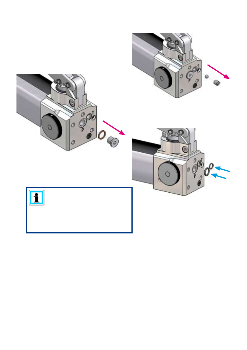
6.1 Basics for mounting base plates and valve blocks
1. Remove the closing screw of the return port
“T” and the ball behind.
2. Remove the closing screw of the pressure
line port “P” and the sealing ring behind.
3. Put the o-rings into the designated groovings
of the ports “T” and “P” .
Take care, that the surfaces are clean and
dust-free.
NOTE:
The o-rings are always part of the
mounting kits of the designated
adapter kits!
(The appropriate mounting kits
could be found in the spare parts
lists.)
12
6.2 Base plates
1. Put the base plate onto the pump head, so
that the boreholes “T” and “P” of the base
plates matches with the ports of the pump
head
Take care, that the surfaces are clean and
dust-free.
2. Put the 4 screws into the designated
boreholes and tighten them with a torque
of 20 Nm.
3. When you are connecting the hose assemblies directly to the hand pump, you will have
to mount appropriate designated couplings, ttings or closing screws to the ports “P” and
“T”. (tightening torque M
= 40 Nm)
A
ATTENTION!
After the end of the assembly close all hydraulic lines by using closing screws
and/or dust protection caps, to prevent the hand pump from impurities.
13
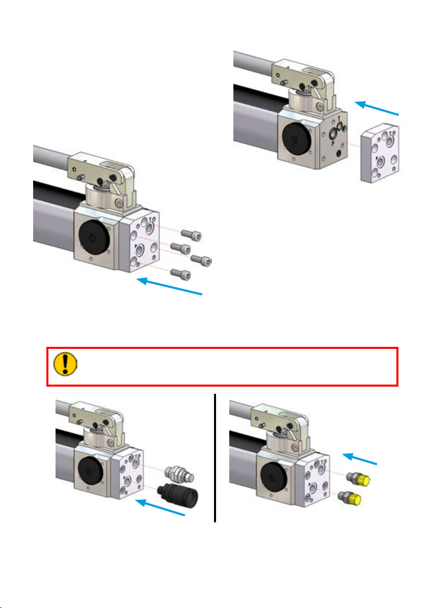
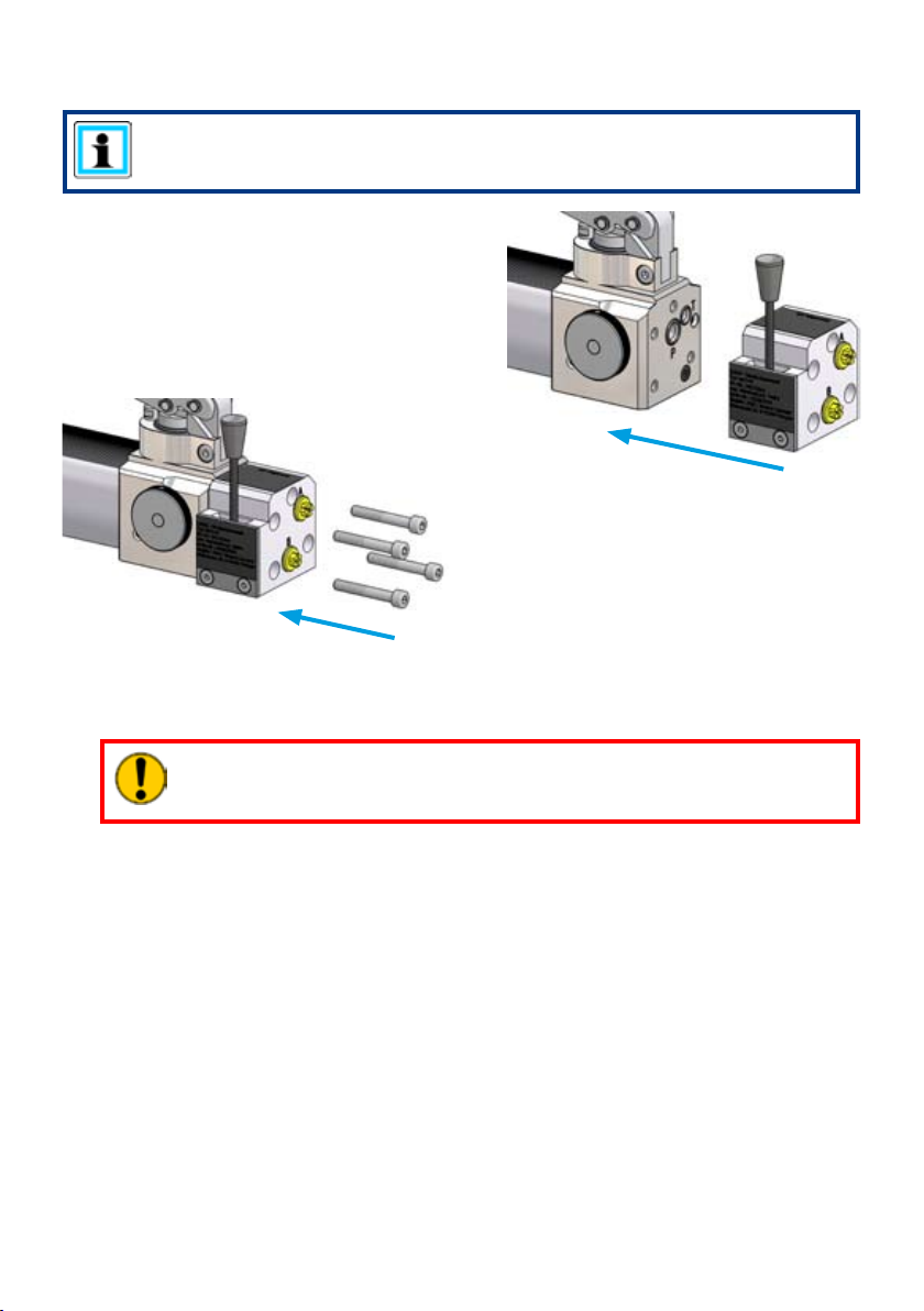
6.3 4/3-way valve
NOTE:
The article description and reference number of all listed position numbers could
be found in the spare parts lists.
1. Put the 4/3-way valve onto the pump head,
so that the boreholes “T” and “P” of the base
plates matches with the ports of the pump
head
Take care, that the surfaces are clean and
dust-free.
2. Put the 4 screws (Pos. 6.1) into the
designated boreholes and tighten them
with a torque of 20 Nm.
3. Now screw on the appropriate designated couplings, ttings or closing screws, to seal
the hand pump again.
(tightening torque M
= 40 Nm)
A
ATTENTION!
After the end of the assembly close all hydraulic lines by using closing screws
and/or dust protection caps, to prevent the hand pump from impurities.
14
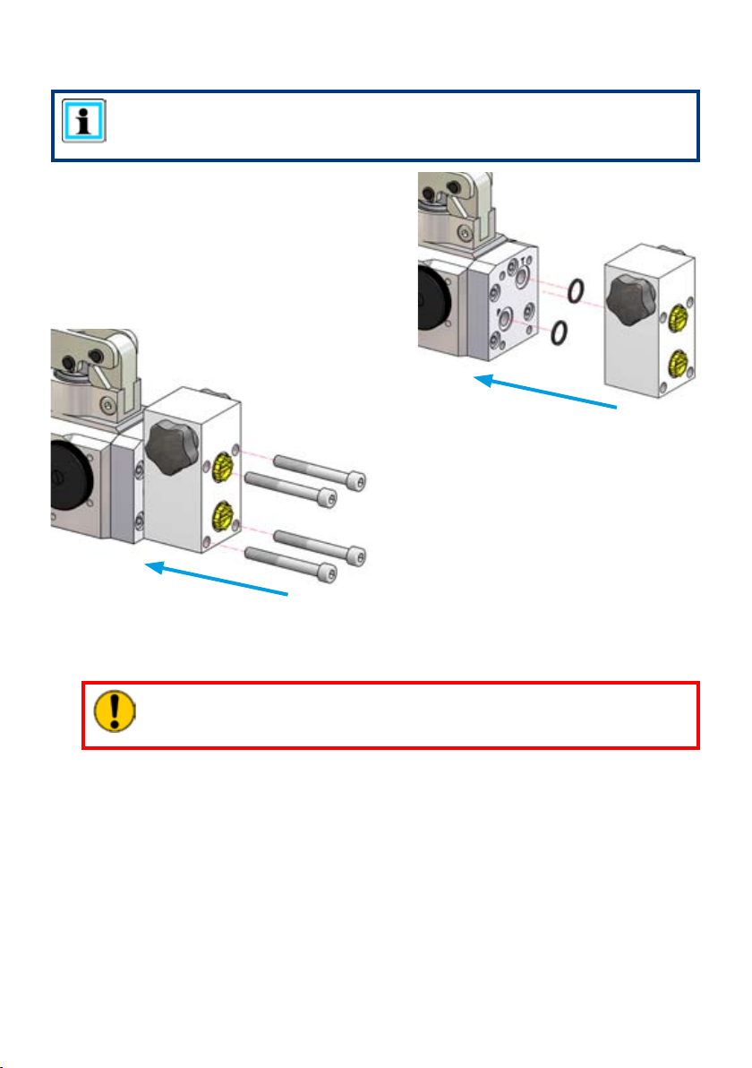
6.4 2-way distribution valve
NOTE:
To mount the 2-way distribution valve, rst the base plate without closing
screws, ttings and couplings has to be mounted.
1. Put the sealing rings and the 2-way
distribution valve onto the pump head, so
that the boreholes “T” and “P” of the 2-way
distribution valve matches with the ports of
the base plate / pump head.
Take care, that the surfaces are clean and
dust-free.
2. Put the 4 screws into the designated
boreholes and tighten them with a torque
of 32 Nm.
3. When you are connecting the hose assemblies directly to the hand pump, you will have
to mount appropriate designated couplings, ttings or closing screws to the ports “P” and
“T”. (tightening torque M
= 40 Nm)
A
ATTENTION!
After the end of the assembly close all hydraulic lines by using closing screws
and/or dust protection caps, to prevent the hand pump from impurities.
 Loading...