

Page 1

Stinger® MRT
Getting Started Guide
Part Number: 7820-0969-017
For software version 9.9.0
February 2006
Page 2

Copyright © 2001, 2002, 2003, 2004, 2006 Lucent Technologies Inc. All rights reserved.
This material is protected by the copyright laws of the United States and other countries. It may not be reproduced, distributed, or altered in
any fashion by any entity (either internal or external to Lucent Technologies), except in accordance with applicable agreements, contracts, or
licensing, without the express written consent of Lucent Technologies. For permission to reproduce or distribute, please email your request to
techcomm@lucent.com.
Notice
Every effort was made to ensure that the information in this document was complete and accurate at the time of printing, but information is
subject to change. For latest information, refer to online product documentation at
European Community (EC) RTTE compliance
www.lucent.com/support.
Hereby, Lucent Technologies, declares that the equipment documented in this publication is in compliance with the essential requirements and other relevant provisions of the Radio and Telecommunications Technical Equipment (RTTE) Directive 1999/5/EC.
To view the official Declaration of Conformity certificate for this equipment, according to EN 45014, access the Lucent INS online documentation
library at
Safety, compliance, and warranty Information
http://www.lucentdocs.com/ins.
Before handling any Lucent Access Networks hardware product, read the Edge Access and Broadband Access Safety and Compliance Guide included
in your product package. See that guide also to determine how products comply with the electromagnetic interference (EMI) and network
compatibility requirements of your country. See the warranty card included in your product package for the limited warranty that Lucent
Technologies provides for its products.
Security statement
In rare instances, unauthorized individuals make connections to the telecommunications network through the use of access features.
Trademarks
Lucent, the Lucent logo, and all Lucent brand and product names are trademarks or registered trademarks of Lucent Technologies Inc. Other
brand and product names are trademarks of their respective holders.
Ordering Information
You can order the most up-to-date product information and computer-based training online at http://www.lucentdocs.com/bookstore.
Feedback
Lucent Technologies appreciates customer comments about this manual. Please send them to techcomm@lucent.com.
Lucent Technologies
Page 3

Customer Service
Product and service information, and software upgrades, are available 24 hours a day.
Technical assistance options accommodate varying levels of urgency.
Finding information and software
To obtain software upgrades, release notes, and addenda for this product, log in to
Lucent OnLine Customer Support at http://www.lucent.com/support.
Lucent OnLine Customer Support also provides technical information, product
information, and descriptions of available services. The center is open 24
seven days a week. Log in and select a service.
Obtaining technical assistance
Lucent OnLine Customer Support at http://www.lucent.com/support provides easy
access to technical support. You can obtain technical assistance through email or the
Internet, or by telephone. If you need assistance, make sure that you have the
following information available:
■ Active service or maintenance contract number, entitlement ID, or site ID
Customer Service
hours a day,
■ Product name, model, and serial number
■ Software version or release number
■ Software and hardware options
■ If supplied by your carrier, service profile identifiers (SPIDs) associated with your
line
■ Your local telephone company’s switch type and operating mode, such as AT&T
5ESS Custom or Northern Telecom National ISDN-1
■ Whether you are routing or bridging with your Lucent product
■ Type of computer you are using
■ Description of the problem
Obtaining assistance through email or the Internet
If your services agreement allows, you can communicate directly with a technical
engineer through Email Technical Support or a Live Chat. Select one of these sites
when you log in to http://www.lucent.com/support.
Calling the technical assistance center (TAC)
If you cannot find an answer through the tools and information of Lucent OnLine
Customer Support or if you have a very urgent need, contact TAC. Access Lucent
OnLine Customer Support at http://www.lucent.com/support and click Contact Us
for a list of telephone numbers inside and outside the United States.
Alternatively, call 1-866-LUCENT8 (1-866-582-3688) from any location in North
America for a menu of Lucent services. Or call +1
510-747-2000 for an operator. You
must have an active services agreement or contract.
Stinger® MRT Getting Started Guide iii
Page 4

Page 5

Contents
Customer Service ........................................................................................................iii
About This Guide .............................................................................xvii
What is in this guide ................................................................................................xvii
What you should know............................................................................................xvii
Documentation conventions ....................................................................................xvii
Stinger documentation set ......................................................................................xviii
Chapter 1 Introduction to the Stinger MRT......................................................1-1
The Stinger MRT ...................................................................................................... 1-1
Virtual slot conventions for the Stinger MRT .......................................................... 1-2
Stinger MRT models and optional products............................................................. 1-2
Chapter 2 Preparing for the Installation...........................................................2-1
Selecting an installation site ..................................................................................... 2-1
Before you begin ...................................................................................................... 2-1
Required tools and equipment ................................................................................. 2-2
Preventing static discharge damage.......................................................................... 2-2
Use a wrist strap................................................................................................. 2-2
Remove plastics from your work area ............................................................... 2-4
Store components properly ............................................................................... 2-4
Unpacking the Stinger MRT ..................................................................................... 2-4
Verifying the hardware configuration...................................................................... 2-4
Stinger MRT interfaces ...................................................................................... 2-5
STS-3 cascading connectors ............................................................................... 2-6
Shelf ID switch................................................................................................... 2-6
Trunk module location ...................................................................................... 2-6
OC3/STM1-ATM trunk modules ....................................................................... 2-7
DS3-ATM trunk modules .................................................................................. 2-8
T1 and E1 trunk modules .................................................................................. 2-9
iii
xvii
xvii
xvii
xvii
xviii
1-1
1-1
1-2
1-2
2-1
2-1
2-1
2-2
2-2
2-2
2-4
2-4
2-4
2-4
2-5
2-6
2-6
2-6
2-7
2-8
2-9
Chapter 3 Installing a Stinger MRT ...................................................................3-1
Before you begin ...................................................................................................... 3-1
Identifying and installing mounting brackets .......................................................... 3-1
Mounting brackets for the Stinger MRT 23 ....................................................... 3-2
Standard mounting brackets ....................................................................... 3-2
Multi-position brackets ............................................................................... 3-2
Installing mounting brackets on the Stinger MRT 23........................................ 3-33-3
Stinger® MRT Getting Started Guide v
3-1
3-1
3-1
3-2
3-2
3-2
Page 6

Contents
Determining proper alignment of the multi-position brackets ................... 3-3
Installing the mounting brackets................................................................. 3-4
Mounting brackets for the Stinger MRT 19 ....................................................... 3-5
23-inch mounting brackets for the Stinger MRT 19 ................................... 3-5
Installing the 23-inch mounting brackets on the Stinger MRT 19.............. 3-5
19-inch ETSI mounting brackets for the Stinger MRT 19 ........................... 3-6
Installing the 19-inch ETSI mounting brackets on the Stinger MRT 19 ..... 3-7
EIA mounting brackets for the Stinger MRT 19.......................................... 3-8
Installing the EIA mounting brackets on the Stinger MRT 19 .................... 3-9
Mounting the MRT in an equipment rack ............................................................... 3-9
Mounting the Stinger MRT units in a 23-inch rack ........................................ 3-10
Mounting the Stinger MRT 19 in smaller equipment racks ............................ 3-10
Installing and removing trunk modules................................................................. 3-12
Installing a trunk module ................................................................................ 3-12
Removing a trunk module............................................................................... 3-13
MRT cooling ........................................................................................................... 3-13
Replacing the cooling module on the Stinger MRT 19 .......................................... 3-14
Connecting cables to a Stinger MRT unit ............................................................... 3-15
50-pin connectors details................................................................................. 3-16
Connecting the subscriber lines ....................................................................... 3-16
Connecting the POTS lines .............................................................................. 3-18
Disconnecting a 50-pin connector ................................................................... 3-19
Recommended method to disconnect a 50-pin connector........................ 3-19
Alternate method to disconnect a 50-pin connector................................. 3-20
Connecting the STS-3 cascading connections.................................................. 3-20
Connecting the trunk module ......................................................................... 3-22
OC3/STM1-ATM trunk module connections ............................................ 3-22
DS3-ATM trunk module connections ....................................................... 3-22
T1 or E1 trunk module connections.......................................................... 3-23
Network management connections ....................................................................... 3-23
System clocking...................................................................................................... 3-24
Alarm monitoring .................................................................................................. 3-24
Connecting to monitor Stinger MRT alarm status ........................................... 3-24
Connecting a Stinger MRT to monitor the alarm status of other devices........ 3-25
3-3
3-4
3-5
3-5
3-5
3-6
3-7
3-8
3-9
3-9
3-10
3-10
3-12
3-12
3-13
3-13
3-14
3-15
3-16
3-16
3-18
3-19
3-19
3-20
3-20
3-22
3-22
3-22
3-23
3-23
3-24
3-24
3-24
3-25
Chapter 4 Determining the Operating Status ..................................................4-1
Before you begin ...................................................................................................... 4-1
Power requirements ................................................................................................. 4-1
Connecting power to a Stinger MRT unit ................................................................ 4-2
Monitoring backup power to a Stinger MRT ........................................................... 4-3
Turning on power to a Stinger MRT unit................................................................. 4-4
Turning off power to a Stinger MRT unit ................................................................ 4-4
Status lights .............................................................................................................. 4-4
Monitoring the status of the DSL ports .................................................................... 4-7
Chapter 5 Stinger MRT Operational Overview ................................................5-1
Stinger MRT operation as a DSL access multiplexer ................................................ 5-1
Operation with integrated splitters .................................................................... 5-1
Operation without splitters................................................................................ 5-2
Stinger MRT ATM switching overview .................................................................... 5-3
Stinger MRT configuration overview ....................................................................... 5-35-3
vi Stinger® MRT Getting Started Guide
4-1
4-1
4-1
4-2
4-3
4-4
4-4
4-4
4-7
5-1
5-1
5-1
5-2
5-3
Page 7

Contents
Administrative configuration............................................................................. 5-4
Line configuration ............................................................................................. 5-4
Trunk module configuration ............................................................................. 5-4
System clocking modes ...................................................................................... 5-5
Stinger MRT management features.......................................................................... 5-5
Using the command-line interface .................................................................... 5-5
Onboard flash memory and software updates ................................................... 5-6
SNMP support.................................................................................................... 5-6
RADIUS support ................................................................................................ 5-6
Tracking system activity..................................................................................... 5-6
What’s next .............................................................................................................. 5-7
Chapter 6 Configuring Administrative Access, System Timing, and Startup
Settings ........................................................................................6-1
Administrative configuration overview ................................................................... 6-1
Making the initial administrative connection .......................................................... 6-2
Logging into the Stinger MRT .................................................................................. 6-3
Restricting administrative access .............................................................................. 6-3
Changing defaults for serial-port logins............................................................. 6-3
Changing the default admin password .............................................................. 6-4
Setting a Telnet password .................................................................................. 6-5
Providing a basic system IP configuration ................................................................ 6-6
IP address syntax ............................................................................................... 6-6
Netmasks............................................................................................................ 6-6
Subnets .............................................................................................................. 6-6
Assigning the Ethernet IP addresses .................................................................. 6-8
Configuring a default route ............................................................................... 6-9
Additional administrative connections and configuration ....................................... 6-9
Connecting to an Ethernet LAN ...................................................................... 6-10
Verifying a LAN connection for administrators ............................................... 6-10
Connecting to and configuring an external modem ........................................ 6-11
Connecting to and configuring an internal modem ........................................ 6-12
Configuring an internal modem................................................................ 6-12
Administrative terminating PVC connections ................................................. 6-13
Overview of a terminating ATM connection ............................................ 6-13
Overview of terminating PVC settings ...................................................... 6-14
Typical terminating PVC configuration for an administrative connection 6-16
Checking the status of a terminating PVC ....................................................... 6-18
Configuring system clocking (optional) ................................................................. 6-19
Using the BITS clock source............................................................................. 6-19
Loss of BITS signal indications and fall-back............................................. 6-19
Changing the BITS clock source................................................................ 6-20
Using a trunk module clock source ................................................................. 6-21
Configuring trunk ports as eligible clock sources ...................................... 6-21
Typical trunk port clock source configurations ......................................... 6-22
Retaining basic configuration settings for remote administration.......................... 6-22
Storing a partial configuration for restart after clearing NVRAM .................... 6-22
Allowing password information in the default.cfg file .............................. 6-23
Creating the default.cfg file ....................................................................... 6-23
Restarting with a partial configuration ............................................................ 6-24
Saving and loading a backup configuration ........................................................... 6-246-24
5-4
5-4
5-4
5-5
5-5
5-5
5-6
5-6
5-6
5-6
5-7
6-1
6-1
6-2
6-3
6-3
6-3
6-4
6-5
6-6
6-6
6-6
6-6
6-8
6-9
6-9
6-10
6-10
6-11
6-12
6-12
6-13
6-13
6-14
6-18
6-19
6-19
6-19
6-20
6-21
6-21
6-22
6-22
6-22
6-23
6-23
6-24
Stinger® MRT Getting Started Guide vii
Page 8

Contents
Saving the configuration.................................................................................. 6-24
Saving the full configuration to a local file ............................................... 6-25
Saving the configuration to a network host.............................................. 6-25
Restoring the configuration ............................................................................. 6-25
Restoring from a local file ......................................................................... 6-25
Restoring from a network host ................................................................. 6-26
Chapter 7 Configuring the ADSL Line Interfaces .............................................7-1
Configuring ATM ADSL-DMT interfaces ................................................................. 7-1
Overview of the AL-DMT profile ....................................................................... 7-2
ADSL protocol support ...................................................................................... 7-2
Line activation and DMT parameters ................................................................ 7-2
AL-DMT profile ........................................................................................... 7-3
Line-Config subprofile................................................................................. 7-3
Rate-adaptive mode parameters.................................................................. 7-5
Power-level parameters and power spectral density (PSD) ........................ 7-6
Fast and interleaved bit-rate parameters ........................................................... 7-7
Fast-Path-Config subprofile......................................................................... 7-7
Interleave-Path-Config subprofile ............................................................... 7-8
Margin-Config subprofile .......................................................................... 7-10
Configuring call control.......................................................................................... 7-11
Examples of ADSL-DMT interface configuration ................................................... 7-13
Checking the status of an ADSL-DMT interface .................................................... 7-14
Checking status of the physical interface......................................................... 7-15
Obtaining statistics about operations ............................................................... 7-16
Displaying ADSL-DMT port status and nailed groups ..................................... 7-18
ADSL line specifications ......................................................................................... 7-18
6-24
6-25
6-25
6-25
6-25
6-26
7-1
7-1
7-2
7-2
7-2
7-3
7-3
7-5
7-6
7-7
7-7
7-8
7-10
7-11
7-13
7-14
7-15
7-16
7-18
7-18
Chapter 8 Configuring the SHDSL line interfaces ............................................8-1
Configuring SHDSL interfaces .................................................................................. 8-1
Configuring port settings for SHDSL.................................................................. 8-2
Sample SHDSL mode configuration .................................................................. 8-9
Binding two SHDSL ports .................................................................................. 8-9
Displaying SHDSL port status .......................................................................... 8-10
Configuring call control.......................................................................................... 8-11
Checking the status of an SHDSL interface ............................................................ 8-12
Checking the status of the physical interface .................................................. 8-13
Obtaining statistics about operations ............................................................... 8-14
Diagnostic internal, external, and bit error-rate tests ............................................ 8-16
Configuring an internal diagnostic test (IDT) .................................................. 8-18
Configuring a bit-error-rate test (BERT).......................................................... 8-19
Configuring an external diagnostic test (EDT) ................................................ 8-19
Digital loopback......................................................................................... 8-20
Analog loopback........................................................................................ 8-20
Interface standards........................................................................................... 8-21
Embedded Operations Channel (EOC) protocol compliance .......................... 8-21
Chapter 9 Configuring T1 and E1 Trunk Modules............................................9-1
Introducing the T1 and E1 trunk modules............................................................... 9-2
Overview of supported features ............................................................................... 9-29-2
8-1
8-1
8-2
8-9
8-9
8-10
8-11
8-12
8-13
8-14
8-16
8-18
8-19
8-19
8-20
8-20
8-21
8-21
9-1
9-2
viii Stinger® MRT Getting Started Guide
Page 9

Contents
Installing a T1 or E1 trunk module .......................................................................... 9-3
Connecting a T1 or E1 trunk module ...................................................................... 9-3
Interpreting T1 or E1 module status lights ............................................................... 9-4
Profiles associated with a T1 or E1 module.............................................................. 9-4
DS1-ATM profile ...................................................................................................... 9-5
DS1-ATM-Stat profile............................................................................................. 9-11
Slot-Static-Config profile ........................................................................................ 9-14
IMAgroup profile.................................................................................................... 9-15
IMAHW-Config profile ........................................................................................... 9-20
IMA-Group-Stat profile.......................................................................................... 9-21
Connection profile.................................................................................................. 9-25
Configuring T1 or E1 module connections ............................................................ 9-28
Typical UNI configuration................................................................................ 9-29
Typical IMA configuration ............................................................................... 9-30
Typical return to UNI configuration from IMA ............................................... 9-32
Considerations for assigning a nailed group number to a DS1-ATM profile ... 9-33
Commands for checking T1 or E1 IMA performance ............................................ 9-34
Checking line status with the IMAlines command.......................................... 9-34
Checking group status with the IMAgroups command ................................... 9-35
Testing connectivity with the IMA-TPP command .......................................... 9-36
T1 and E1 module specifications ............................................................................ 9-36
Specifications common to T1 and E1 line modules ......................................... 9-36
Specifications unique to T1 line modules ........................................................ 9-38
Specifications unique to E1 line modules ........................................................ 9-39
Compliance with IMA specifications ............................................................... 9-39
Compliance with ATM specifications............................................................... 9-41
9-3
9-3
9-4
9-4
9-5
9-11
9-14
9-15
9-20
9-21
9-25
9-28
9-29
9-30
9-32
9-33
9-34
9-34
9-35
9-36
9-36
9-36
9-38
9-39
9-39
9-41
Chapter 10 Configuring an OC3-ATM Trunk Module ......................................10-1
Installing an OC3-ATM trunk module ................................................................... 10-1
Connecting an OC3-ATM trunk module ............................................................... 10-1
Interpreting OC3-ATM status lights ....................................................................... 10-2
Configuring an OC3-ATM trunk module............................................................... 10-3
Overview of OC3-ATM settings ....................................................................... 10-3
Displaying OC3-ATM status and nailed groups ............................................... 10-5
Changing physical-layer interface settings ...................................................... 10-6
Call control............................................................................................................. 10-6
Example of OC3-ATM configuration ..................................................................... 10-6
Checking OC3-ATM trunk interface status ............................................................ 10-6
Monitoring the OC3 interface.......................................................................... 10-7
Monitoring errors and performance of the SONET payload............................ 10-9
SONET performance and error counters ................................................. 10-10
Performance-Monitoring and Interval-Performance-Monitoring
subprofiles .................................................................................. 10-11
OC3-ATM trunk module specifications................................................................ 10-13
Module specifications .................................................................................... 10-13
Cable specifications ........................................................................................ 10-14
Chapter 11 Configuring a DS3-ATM Trunk Module.........................................11-1
Installing a DS3-ATM trunk module...................................................................... 11-1
Connecting a DS3-ATM trunk module .................................................................. 11-2
Interpreting DS3-ATM status lights ....................................................................... 11-211-2
10-1
10-1
10-1
10-2
10-3
10-3
10-5
10-6
10-6
10-6
10-6
10-7
10-9
10-10
10-11
10-13
10-13
10-14
11-1
11-1
11-2
Stinger® MRT Getting Started Guide ix
Page 10

Contents
Configuring a DS3-ATM trunk module ................................................................. 11-3
Displaying DS3-ATM port status and nailed groups ........................................ 11-5
Setting DS3 framing formats............................................................................ 11-6
Call control............................................................................................................. 11-6
Example of DS3-ATM configuration ...................................................................... 11-6
Checking DS3-ATM trunk interface status ............................................................ 11-7
Traffic aggregation with the DS3-ATM module ..................................................... 11-9
DS3-ATM traffic aggregation connection ........................................................ 11-9
Aggregation failure protection with the DS3-ATM bypass feature................ 11-10
DS3-ATM trunk module specifications ................................................................ 11-10
Appendix A Stinger MRT Intended Use...............................................................A-1
User line interfaces ...................................................................................................A-1
Network interfaces ...................................................................................................A-1
Administrative interfaces .........................................................................................A-2
Appendix B Hosted Operation of Cascaded Stinger MRT units........................ B-1
Introduction to the host management interface ...................................................... B-1
Configuring hosted MRT system operations ............................................................ B-2
Cabling Stinger MRT units together ..................................................................B-3
Configuring the remote shelves.........................................................................B-4
Configuring the host system to operate in master mode ................................... B-5
Enabling the remote shelves in the hosted system............................................B-5
Checking the hosted system topology ............................................................... B-6
Provisioning virtual circuits in the hosted system ............................................. B-7
Restoring a remote shelf to standalone operations............................................ B-8
Traffic management in hosted MRT systems ...........................................................B-8
Deprecated atm-config profile...........................................................................B-8
LIM slot CAC support ........................................................................................ B-9
Hosted MRT system bandwidth and CAC calculations......................................B-9
Upstream traffic shaping in a hosted system ................................................... B-11
Hosted MRT system management..........................................................................B-11
Upgrading hosted MRT system software ......................................................... B-11
Required steps before initializing NVRAM in the host..............................B-12
Automatic upgrade procedure...................................................................B-12
Manual upgrade via loadslave (optional procedure) ............................... B-13
Resetting a hosted system ......................................................................... B-14
Monitoring remote LIMs and connections ...................................................... B-15
Displaying status of remote DSL lines ....................................................... B-15
Displaying shelf-specific ATM connection and signaling information ......B-15
Monitoring the status of remote shelves ......................................................... B-16
Using the remote-shelf-stat profile ........................................................ B-16
Using the remoteshelf command..............................................................B-17
Setting alarms for events on remote shelves ............................................. B-18
Enabling traps for events on remote shelves............................................. B-20
Displaying hosted MRT system topology and statistics .................................... B-22
Displaying the entire topology ..................................................................B-22
Displaying a picture of the topology..........................................................B-24
Displaying the details for a specific shelf ................................................... B-24
Displaying statistics for a specific shelf ...................................................... B-24
Sending an init packet to a remote shelf ................................................... B-26B-26
11-3
11-5
11-6
11-6
11-6
11-7
11-9
11-9
11-10
11-10
A-1
A-1
A-1
A-2
B-1
B-1
B-2
B-3
B-4
B-5
B-5
B-6
B-7
B-8
B-8
B-8
B-9
B-9
B-11
B-11
B-11
B-12
B-12
B-13
B-14
B-15
B-15
B-15
B-16
B-16
B-17
B-18
B-20
B-22
B-22
B-24
B-24
B-24
x Stinger® MRT Getting Started Guide
Page 11

Contents
Appendix C Cables and Connectors .................................................................... C-1
CONSOLE port and cable pinouts ............................................................................C-1
Alarm connector pinouts .........................................................................................C-2
Ethernet interface specifications ..............................................................................C-3
STS-3 (synchronous transport signals-3) connector specifications .......................... C-3
50-pin telephone company connector cable specifications...................................... C-4
Pinouts for subscriber line DSL connections......................................................C-4
Pinouts for POTS connections to a voice switch................................................ C-7
T1 and E1 connector and cable specifications ..........................................................C-9
T1 and E1 connector specifications....................................................................C-9
T1 and E1 cable specifications............................................................................ C-9
T1 or E1 crossover cable: RJ-48C/RJ-48C .................................................C-10
T1 or E1 straight-through cable: RJ-48C/RJ-48C .....................................C-11
T1 or E1 straight-through cable: RJ-48C/DB-15 ....................................... C-12
T1 or E1 crossover cable: RJ-48C/DB-15 .................................................. C-13
T1 or E1 straight-through cable: RJ-48C/Bantam..................................... C-14
T1 or E1 RJ-48C-Loopback plug ............................................................... C-14
C-1
C-1
C-2
C-3
C-3
C-4
C-4
C-7
C-9
C-9
C-9
C-10
C-11
C-12
C-13
C-14
C-14
Appendix D Safety-Related Electrical, Physical, and Environmental
Information .................................................................................D-1
Electrical and electronic information .......................................................................D-1
Electronic and electrical specifications...............................................................D-1
USOC jack and code information ......................................................................D-2
ADSL line ringer equivalence number (REN) ...................................................D-3
EMI compatibility ..............................................................................................D-3
Certifications ......................................................................................................D-4
Minimum ground wire size ...............................................................................D-4
Physical specifications ..............................................................................................D-4
Safety certifications ..................................................................................................D-5
Site specifications .....................................................................................................D-5
Operating environment .....................................................................................D-5
Space requirements ...........................................................................................D-6
D-1
D-1
D-1
D-2
D-3
D-3
D-4
D-4
D-4
D-5
D-5
D-5
D-6
Index .....................................................................................................1
Stinger® MRT Getting Started Guide xi
Page 12

Page 13

Figures
Figure 2-1 Wrist grounding strap ....................................................................... 2-3
Figure 2-2 Wrist strap plugged into a grounding jack ........................................ 2-3
Figure 2-3 Stinger MRT 23 chassis connectors ................................................... 2-5
Figure 2-4 Stinger MRT 19 chassis connectors ................................................... 2-5
Figure 2-5 Stinger MRT 23 trunk module location ............................................ 2-7
Figure 2-6 Stinger MRT 19 trunk module location ............................................ 2-7
Figure 2-7 OC3-ATM trunk module for the MRT 23 chassis ............................. 2-8
Figure 2-8 OC3-ATM trunk module for the MRT 19 chassis ............................. 2-8
Figure 2-9 DS3-ATM trunk module for the MRT 23 chassis .............................. 2-9
Figure 2-10 DS3-ATM trunk module for the MRT 19 chassis .............................. 2-9
Figure 2-11 T1 or E1 trunk module for the MRT 23 chassis ................................ 2-9
Figure 2-12 T1 or E1 trunk module for the MRT 19 chassis ................................ 2-9
Figure 3-1 Stinger MRT 23 mounting brackets .................................................. 3-2
Figure 3-2 Multi-position mounting brackets..................................................... 3-3
Figure 3-3 Determining the mounting position of the multi-position bracket... 3-4
Figure 3-4 Installing mounting brackets............................................................. 3-4
Figure 3-5 23-inch rack mounting brackets for the Stinger MRT 19 ................. 3-5
Figure 3-6 Installing 23-inch brackets on the Stinger MRT 19........................... 3-6
Figure 3-7 19-inch rack mounting brackets for the Stinger MRT 19 ................. 3-7
Figure 3-8 Installing ETSI 19-inch brackets on the MRT 19............................... 3-8
Figure 3-9 EIA rack mounting brackets for the Stinger MRT 19 ........................ 3-8
Figure 3-10 Installing EIA brackets on the MRT 19 ............................................. 3-9
Figure 3-11 Placing Stinger MRT 23 and Stinger MRT 19 chassis in a 23-inch
rack.................................................................................................. 3-10
Figure 3-12 Placing Stinger MRT 19 chassis in a smaller equipment rack ......... 3-11
Figure 3-13 Installing an MRT 23 trunk module................................................ 3-12
Figure 3-14 Installing an MRT 19 trunk module................................................ 3-13
Figure 3-15 Removing the cooling module of a Stinger MRT 19 ....................... 3-14
Figure 3-16 Installing a replacement cooling module ........................................ 3-15
Figure 3-17 50-pin connector security mechanisms........................................... 3-16
Figure 3-18 Connecting the subscriber lines to the Stinger MRT 23 .................. 3-17
Figure 3-19 Connecting the subscriber lines to the Stinger MRT 19 .................. 3-18
Figure 3-20 Connecting the POTS lines.............................................................. 3-19
Figure 3-21 Removing the 50-pin connector (recommended method) ............. 3-20
Figure 3-22 Removing the 50-pin connector (alternate method) ...................... 3-20
Figure 3-23 Connecting the STS-3 cascading connection .................................. 3-21
Figure 3-24 Connecting an OC3-ATM trunk module ........................................ 3-22
Figure 3-25 Connecting DS3-ATM trunk modules ............................................ 3-23
Figure 3-26 Connecting a T1 or E1 trunk module ............................................. 3-23
Figure 4-1 Removing the power terminal shield of a Stinger MRT 23............... 4-2
Figure 4-2 Connecting the -48Vdc power filters on the MRT 23 ....................... 4-3
Figure 4-3 Connecting the -48Vdc power filters on the MRT 19 ....................... 4-3
Figure 4-4 Stinger MRT 23 status light locations................................................ 4-54-5
2-3
2-3
2-5
2-5
2-7
2-7
2-8
2-8
2-9
2-9
2-9
2-9
3-2
3-3
3-4
3-4
3-5
3-6
3-7
3-8
3-8
3-9
3-10
3-11
3-12
3-13
3-14
3-15
3-16
3-17
3-18
3-19
3-20
3-20
3-21
3-22
3-23
3-23
4-2
4-3
4-3
Stinger® MRT Getting Started Guide xiii
Page 14

Figures
Figure 4-5 Stinger MRT 19 Status light locations ............................................... 4-5
Figure 4-6 The port group selector switch and group indicator LED.................. 4-7
Figure 5-1 Example of DSLAM operations with splitters for POTS service ........ 5-2
Figure 5-2 Example of pure DSLAM operation .................................................. 5-3
Figure 6-1 Serial management connection to the Stinger MRT ......................... 6-2
Figure 6-2 Default netmask for class C IP address .............................................. 6-6
Figure 6-3 Local backbone router to be used as default route............................ 6-9
Figure 6-4 Ethernet connection........................................................................ 6-10
4-5
4-7
5-2
5-3
6-2
6-6
6-9
6-10
Figure 6-5 Administrative connection with a modem to the Stinger MRT
unit.................................................................................................. 6-11
Figure 6-6 Connection for internal modem...................................................... 6-12
Figure 6-7 Terminating ATM connection ......................................................... 6-14
Figure 6-8 Management connection from a remote network .......................... 6-17
6-11
6-12
6-14
6-17
Figure 7-1 Relationship between noise margin parameters and power
adjustments ..................................................................................... 7-10
Figure 7-2 ADSL ATM configuration................................................................ 7-13
Figure 8-1 Digital loopback............................................................................... 8-20
Figure 8-2 Analog loopback.............................................................................. 8-20
Figure 9-1 T1 or E1 trunk module for a Stinger MRT 23 ................................... 9-3
Figure 9-2 Connecting a T1 or E1 trunk module for the MRT 23 ...................... 9-3
Figure 9-3 Connecting a T1 or E1 trunk module for the MRT 19 ...................... 9-3
Figure 9-4 Sample UNI configuration links ...................................................... 9-29
Figure 9-5 Sample IMA configuration links ..................................................... 9-31
Figure 10-1 Connecting an OC3-ATM trunk module for an MRT 23 ................ 10-2
Figure 10-2 Connecting an OC3-ATM trunk module for an MRT 19 ................ 10-2
Figure 10-3 OC3-ATM trunk module................................................................. 10-3
Figure 10-4 SONET layers................................................................................. 10-10
Figure 11-1 Connecting a DS3-ATM trunk module for the Stinger MRT 23 ..... 11-2
7-10
7-13
8-20
8-20
9-3
9-3
9-3
9-29
9-31
10-2
10-2
10-3
10-10
11-2
Figure 11-2 Front panel of the DS3-ATM trunk module for the Stinger
MRT 23............................................................................................ 11-3
Figure 11-3 DS3-ATM traffic aggregation connection ........................................ 11-9
Figure B-1 Hosted MRT system........................................................................... B-3
Figure B-2 SHELF ID switch on a Stinger MRT back panel ................................ B-4
Figure B-3 Sample hosted virtual circuit configuration ...................................... B-7
11-3
11-9
B-3
B-4
B-7
Figure B-4 Slot-level CAC bandwidth calculations performed with default
settings ............................................................................................ B-10
Figure B-5 Port-level CAC sequence (performed only at provisioning time) ... B-11
Figure C-1 USOC RJ-21X 50-pin connector ....................................................... C-4
Figure C-2 RJ-48C/RJ-48C crossover cable. ..................................................... C-10
Figure C-3 RJ-48C/RJ-48C straight-through cable specifications ..................... C-11
Figure C-4 RJ-48C/DB-15 straight-through cable ............................................ C-12
Figure C-5 RJ-48C/DB-15 crossover cable........................................................ C-13
B-10
B-11
C-4
C-10
C-11
C-12
C-13
Figure C-6 RJ-48C/Bantam straight-through cable .......................................... C-14C-14
xiv Stinger® MRT Getting Started Guide
Page 15

Tab le s
Table 1-1 Stinger MRT virtual slots................................................................... 1-2
Table 1-2 Stinger MRT models and optional products ...................................... 1-3
Table 3-1 Alarm connector pinouts for Stinger MRT alarms .......................... 3-25
Table 3-2 Alarm connector pinouts for monitoring the alarm status of remote
devices ............................................................................................. 3-25
Table 4-1 Status lights on the Stinger MRT 23 and MRT 19............................. 4-5
Table 5-1 Location of configuration information .............................................. 5-7
Table 6-1 IP address classes and number of network bits ................................. 6-6
Table 6-2 Decimal subnet masks and prefix lengths ......................................... 6-7
Table 9-1 T1 and E1 trunk module port connector status lights....................... 9-4
Table 9-2 Descriptions of IMA command output............................................ 9-34
Table 9-3 T1 and E1 line module specifications .............................................. 9-36
Table 9-4 T1-specific specifications ................................................................. 9-38
Table 9-5 E1-specific specifications ................................................................. 9-39
Table 9-6 IMA specifications ........................................................................... 9-39
Table 9-7 ATM specifications .......................................................................... 9-41
Table 10-1 DS3-ATM trunk module status lights ............................................. 10-3
Table 10-2 Descriptions of atmtrunks command output .................................. 10-5
Table 10-3 OC3-ATM module specifications................................................... 10-13
Table 10-4 OC3-ATM cable specifications....................................................... 10-14
Table 11-1 DS3-ATM trunk module status lights ............................................. 11-3
Table 11-2 DS3-ATM trunk module specifications ......................................... 11-10
Table B-1 Default allocation of unique nailed-group numbers to remote
shelves ............................................................................................... B-7
Table B-2 New locations for traffic management settings ................................. B-8
Table B-3 Hosted MRT alarm events ............................................................... B-19
Table B-4 Details displayed for each shelf in the topology .............................. B-23
Table B-5 Statistics displayed for a remote shelf ............................................. B-25
Table B-6 Statistics displayed for the host shelf............................................... B-25
Table B-7 Statistics displayed in an open session on the remote shelf ............ B-26
Table C-1 CONSOLE serial port and cable pinouts............................................ C-1
Table C-2 Alarm input pinouts.......................................................................... C-2
Table C-3 RJ-45 connector (normal end).......................................................... C-3
Table C-4 RJ-45 connector (crossover end) ...................................................... C-3
Table C-5 Cable pinouts for the 1-24 LINE or PORTS connector ...................... C-5
Table C-6 Cable pinouts for the 25-48 LINE or PORTS connector.................... C-6
Table C-7 Cable pinouts for the 1-24 POTS connector...................................... C-7
Table C-8 Cable pinouts for the 25-48 POTS connector.................................... C-8
Table C-9 Transmit and receive pins assignments for T1 and E1 trunk
module connectors............................................................................ C-9
Table C-10 RJ-48C/RJ-48C crossover cable specifications ................................ C-10
Table C-11 RJ-48C/RJ-48C straight-through cable specifications..................... C-11
Table C-12 RJ-48C/DB-15 straight-through cable specifications ...................... C-12C-12
1-2
1-3
3-25
3-25
4-5
5-7
6-6
6-7
9-4
9-34
9-36
9-38
9-39
9-39
9-41
10-3
10-5
10-13
10-14
11-3
11-10
B-7
B-8
B-19
B-23
B-25
B-25
B-26
C-1
C-2
C-3
C-3
C-5
C-6
C-7
C-8
C-9
C-10
C-11
Stinger® MRT Getting Started Guide xv
Page 16

Tables
Table C-13 RJ-48C/DB-15 crossover cable specifications.................................. C-13
Table C-14 RJ-48C/Bantam straight-through cable specifications .................... C-14
Table C-15 RJ-48C-Loopback plug specifications.............................................. C-14
Table D-1 Stinger MRT electronic and electrical specifications ......................... D-1
Table D-2 Stinger MRT T1 and E1 module USOC jacks and codes.................... D-2
Table D-3 Ringer equivalence number ratings .................................................. D-3
Table D-4 Stinger MRT minimum ground wire sizes ........................................ D-4
Table D-5 Stinger MRT physical specifications ................................................. D-4
Table D-6 Stinger MRT site specifications.......................................................... D-5
C-13
C-14
C-14
D-1
D-2
D-3
D-4
D-4
D-5
xvi Stinger® MRT Getting Started Guide
Page 17

About This Guide
What is in this guide
This guide explains how to perform the following installation and basic configuration
tasks on a Stinger MRT (Micro-Remote Terminal) unit:
■ Physical installation of a Stinger MRT unit
■ Connection of an administrative terminal to a Stinger MRT
■ Configuration of a Stinger MRT for basic network connectivity
This guide also provides Stinger MRT technical specifications and an operational
overview of the Stinger MRT. When you finish performing the instructions in this
guide, your Stinger MRT will be installed and you will be able to access it via a Telnet
connection for further configuration.
What you should know
Warning Before installing your Stinger MRT unit, be sure to read the safety
instructions in the Edge Access and Broadband Access Safety and Compliance Guide. For
information specific to your unit, see
Physical, and Environmental Information,” in this guide.
Appendix D, “Safety-Related Electrical,
The procedures in this guide require you to understand and follow the safety
practices at your site, as well as those identified in this guide. Before installing any
hardware, check the installation location for adequate temperature, humidity, and
electrical requirements. Work closely with the network manager and other systems
integration personnel to ensure a functional installation.
Documentation conventions
Following are all the special characters and typographical conventions used in this
manual:
Convention Meaning
Monospace text Represents text that appears on your computer’s screen, or that
could appear on your computer’s screen.
Boldface
monospace text
Stinger® MRT Getting Started Guide xvii
Represents characters that you enter exactly as shown (unless
the characters are also in italics—see Italics, below). If you
could enter the characters but are not specifically instructed to,
they do not appear in boldface.
Page 18
About This Guide
Stinger documentation set
Convention Meaning
Italics Represent variable information. Do not enter the words
[ ] Square brackets indicate an optional argument you might add
| Separates command choices that are mutually exclusive.
> Points to the next level in the path to a parameter or menu
Key1+Key2 Represents a combination keystroke. To enter a combination
Press Enter Means press the Enter or Return key or its equivalent on your
themselves in the command. Enter the information they
represent. In ordinary text, italics are used for titles of
publications, for some terms that would otherwise be in
quotation marks, and to show emphasis.
to a command. To include such an argument, type only the
information inside the brackets. Do not type the brackets unless
they appear in boldface.
item. The item that follows the angle bracket is one of the
options that appear when you select the item that precedes the
angle bracket.
keystroke, press the first key and hold it down while you press
one or more other keys. Release all the keys at the same time.
(For example, Ctrl+H means hold down the Ctrl key and press
the H key.)
computer.
Introduces important additional information.
Note
!
Caution
Warning
Warning
Warns that a failure to follow the recommended procedure
could result in loss of data or damage to equipment.
Warns that a failure to take appropriate safety precautions
could result in physical injury.
Warns of danger of electric shock.
Stinger documentation set
The Stinger documentation set consists of the following manuals, which can be found
at http://www.lucent.com/support and http://www.lucentdocs.com/ins:
■ Read me first:
– Edge Access and Broadband Access Safety and Compliance Guide. Contains
important safety instructions and country-specific information that you must
read before installing a Stinger unit.
– TAOS Command-Line Interface Guide. Introduces the TAOS command-line
environment and shows you how to use the command-line interface
xviii Stinger® MRT Getting Started Guide
Page 19

About This Guide
Stinger documentation set
effectively. This guide describes keyboard shortcuts and introduces
commands, security levels, profile structure, and parameter types.
■ Installation and basic configuration:
– Getting Started Guide for your unit. Shows how to install your Stinger chassis
and hardware. This guide shows you how to use the command-line interface
to configure and verify IP access and basic access security on the unit.
The Getting Started Guides for Stinger models with redundant control
modules describe configuration of this feature.
The Stinger MRT Getting Started Guide describes the features and basic
configuration of the trunk modules that are specific to a Stinger MRT.
– Module guides for each type of module designed for the Stinger FS, Stinger
FS+, Stinger LS, or Stinger RT, an individual guide describes the module's
features and provides instructions for configuring the module and verifying
its status.
■ Configuration:
– Stinger ATM Configuration Guide. Describes how to use the command-line
interface to configure Asynchronous Transfer Mode (ATM) operations on a
Stinger unit. The guide explains how to configure permanent virtual circuits
(PVCs), and shows how to use standard ATM features such as quality of
service (QoS), connection admission control (CAC), and subtending.
– Stinger IP2000 Configuration Guide. For Stinger systems with the IP2000
control module, this guide describes how to integrate the system into the IP
infrastructure. Topics include IP-routed switch-through ATM PVCs and RFC
1483 PVCs that terminate on the IP2000, IEEE 802.1Q VLAN, and
forwarding multicast video transmissions on DSL interfaces.
– Stinger Private Network-to-Network Interface (PNNI) Supplement. Provides
quick-start instructions for configuring PNNI and soft PVCs (SPVCs), and
describes the related profiles and commands in the Stinger command-line
interface.
– Stinger SNMP Management of the ATM Stack Supplement. Describes Simple
Network Management Protocol (SNMP) management of ATM ports,
interfaces, and connections on a Stinger unit to provide guidelines for
configuring and managing ATM circuits through any SNMP management
utility.
■ RADIUS: TAOS RADIUS Guide and Reference. Describes how to set up a TAOS unit
to use the Remote Authentication Dial-In User Service (RADIUS) server and
contains a complete reference to RADIUS attributes.
■ Administration and troubleshooting: Stinger Administration Guide. Describes
how to administer the Stinger unit and manage its operations. Each chapter
focuses on a particular aspect of Stinger administration and operations. The
chapters describe tools for system management, network management, and
Simple Network Management Protocol (SNMP) management.
■ Reference:
– Stinger Reference. An alphabetic reference to Stinger profiles, parameters, and
commands.
– TAOS Glossary. Defines terms used in documentation for Stinger units.
Stinger® MRT Getting Started Guide xix
Page 20

Page 21

Introduction to the Stinger MRT
1
The Stinger MRT . . . . . . . . . . . . . . . . . . . . . . . . . . . . . . . . . . . . . . . . . . . . . . . . . 1-1
Virtual slot conventions for the Stinger MRT. . . . . . . . . . . . . . . . . . . . . . . . . . . . 1-2
Stinger MRT models and optional products . . . . . . . . . . . . . . . . . . . . . . . . . . . . . 1-21-2
The Stinger MRT
The Stinger MRT is a small temperature-hardened version of the Stinger unit,
designed to be installed in outdoor enclosures in remote locations. The operating
temperature of the installation environment can range between -40°F (-40°C) and
149°F (+65°C). (For more information, see
Two types of MRT chassis are available.
■ The Stinger MRT 23—for installation in standard 23-inch racks
■ The Stinger MRT 19—for installation in standard 19-inch racks, or racks with at
least 17.72 inches of space between the mounting rails
Each chassis supports different numbers of DSL lines, and types of DSL service, for
details see
The Stinger MRT chassis have an integrated design, unlike the chassis of larger
Stinger LS and Stinger FS models which have numerous slots that accept different
types of plug-in modules. Plug-in modules for the larger Stinger LS and Stinger FS
support the following functions.
1-1
1-2
“Operating environment” on page D-5.)
“Stinger MRT models and optional products” on page 1-2.
■ General control and configuration of the Stinger unit (control modules)
■ Connection to subscriber lines (line interface modules or LIMs)
■ Protection of the unit from transient subscriber line conditions (line protection
modules or LPMs)
■ Connection to various types of ATM links (trunk modules)
All the hardware and capabilities associated with the control module, LIMs, and
LPMs on the larger Stinger LS and Stinger FS models are integrated into the Stinger
MRT 19 and Stinger MRT 23 chassis.
Depending on bandwidth requirements, a specially designed trunk module that
supports OC3/STM1, DS3, T1, or E1 service can be installed in the Stinger MRT
chassis. Each Stinger MRT chassis is equipped with a pair of STS-3 connectors that
can forward (cascade) traffic through multiple Stinger MRT units in a common
location to a single unit with a trunk module.
Stinger® MRT Getting Started Guide 1-1
Page 22

Introduction to the Stinger MRT
Virtual slot conventions for the Stinger MRT
Some Stinger MRT models also incorporate integrated line splitters to provide
asymmetric digital subscriber line (ASDL) and analog telephone (POTS) service over
a single pair of wires. For chassis details, including model number designations, and
line capabilities, see
Table 1-2.
Virtual slot conventions for the Stinger MRT
The highly integrated Stinger MRT 19 and Stinger MRT 23 use the same TAOS
software as larger Stinger units. In the larger Stinger units TAOS uses the physical slot
number in which modules are installed to access the parameters of those modules
and configure them. In the Stinger MRT, functions are grouped into virtual slots, so
that they can be accessed and configured by the TAOS software in a manner similar
to other Stinger models.
Table 1-1 compares the physical slot locations of modules installed in a Stinger FS
with the virtual slot locations for the same functions integrated into the Stinger MRT.
These virtual slot positions are used in examples throughout this document.
Table 1-1. Stinger MRT virtual slots
Module type Stinger FS location Stinger MRT virtual
location
Line interface module
(LIM)
Control module Slots 8 and 9 Virtual slot 8
Trunk modules Slots 17 and 18 Virtual slot 17 (built-in STS-3)
Slots 1 through 7
Slots 10 through 16
Virtual slot 1
Virtual slot 18 (trunk module)
Stinger MRT models and optional products
Two models of the Stinger MRT 23 are available to support different ADSL line
lengths. The original Stinger MRT 23 was designed for field installations with short
ADSL subscriber loops. This model supports speeds up to 8.128Kbps over 24
American wire gauge (AWG, 0.25 mm²) copper facilities up to 2000 feet, and lower
speeds beyond that distance.
A newer standard-reach version of the MRT 23 supports the standard ADSL
subscriber loop length, identical to the full-sized central office version of the Stinger.
This standard-reach version supports speeds up to 8.128Kbps over 24 AWG (0.25
mm²) copper facilities up to 8000 feet in length, and lower speeds beyond that
distance.
Two models of the MRT 19 are also available. One model of the MRT 19 supports up
to 48 ADSL connections without POTS capability, and another supports up to 36
SHDSL connections.
The two versions of the Stinger MRT 23 can be ordered with different trunk modules
or software options installed for different bandwidth requirements. Trunk modules
for the Stinger MRT 19 models are ordered separately, the base chassis are supplied
with a blank faceplate covering the trunk module slot. Optional software is available
1-2 Stinger® MRT Getting Started Guide
Page 23

Introduction to the Stinger MRT
Stinger MRT models and optional products
that enables additional capabilities of the T1 and E1 trunk module on both models of
the Stinger MRT.
Table 1-2 contains a list of some of the Stinger MRT products that are currently
available. For additional information, contact your Lucent Technologies sales
representative.
Table 1-2. Stinger MRT models and optional products
Product Code Description
MRT-AD-36S
MRT-AD-36S-56K
MRT-AD-36S-SR
MRT-AD-36S-SR-56K
MRT-AD-36S-4T1
MRT-AD-36S-4T1-IMA
MRT-AD-36S-SR-4T
MRT-AD-36S-SR-4T-I
MRT-AD-36S-SR-56K-4T
MRT-AD-36S-SR-56K-4T-I
MRT-AD-36S-8T1
MRT-AD-36S-8T1-IMA
MRT-AD-36S-SR-8T
MRT-AD-36S-SR-8T-I
MRT-AD-36S-SR-56K-8T
MRT-AD-36S-SR-56K-8T-I
MRT-AD-36S-4E1
MRT-AD-36S-4E1-IMA
MRT-AD-36S-SR-4E
MRT-AD-36S-SR-4E-I
MRT-AD-36S-SR-56K-4E
MRT-AD-36S-SR-56K-4E-I
Complete Stinger MRT 23 chassis, 21.5-inch
(54.6cm) wide with 36 ADSL ports and integrated
POTS splitters and blank panel cover for the trunk
module slot. (Models with -56K designation
indicates an internal 56Kbps analog modem. The
-SR designation indicates standard-reach ADSL
capability.)
Complete Stinger MRT 23 chassis, 21.5-inch
(54.6cm) wide, equipped with four T1 ports active
on a T1/E1 trunk module. (The -SR designation
indicates standard-reach ADSL capability. The
-56K designation indicates an internal 56Kbps
analog modem. The -I and -IMA designations
indicate bundled IMA capability.)
Complete Stinger MRT 23 chassis, 21.5-inch
(54.6cm) wide, equipped with eight T1 ports
active on a T1/E1 trunk module. (The -SR
designation indicates standard-reach ADSL
capability. The -56K designation indicates an
internal 56Kbps analog modem. The -I and -IMA
designations indicate bundled IMA capability.)
Complete Stinger MRT 23 chassis, 21.5-inch
(54.6cm) wide, equipped with four E1 ports
active on a T1/E1 trunk module. (The -SR
designation indicates standard-reach ADSL
capability. The -56K designation indicates an
internal 56Kbps analog modem. The -I and -IMA
designations indicate bundled IMA capability.)
MRT-AD-36S-8E1
MRT-AD-36S-8E1-IMA
MRT-AD-36S-SR-8E
MRT-AD-36S-SR-8E-I
MRT-AD-36S-SR-56K-8E
MRT-AD-36S-SR-56K-8E-I
Complete Stinger MRT 23 chassis, 21.5-inch
(54.6cm) wide, equipped with eight E1 ports
active on a T1/E1 trunk module. (The -SR
designation indicates standard-reach ADSL
capability. The -56K designation indicates an
internal 56Kbps analog modem. The -I and -IMA
designations indicate bundled IMA capability.)
MRT-TM-T1E1 Replacement T1/E1 trunk module for a Stinger
MRT 23 chassis.
Stinger® MRT Getting Started Guide 1-3
Page 24

Introduction to the Stinger MRT
Stinger MRT models and optional products
Table 1-2. Stinger MRT models and optional products
Product Code Description
MRT-AD-36S-2OC3
MRT-AD-36S-SR-2OC3
MRT-AD-36S-SR-56K-2OC3
Complete Stinger MRT 23 chassis, 21.5-inch
(54.6cm) wide, equipped with two OC3/STM1
ports on an OC3 trunk module. (The -SR
designation indicates standard-reach ADSL
capability. The -56K designation indicates an
internal 56Kbps analog modem.)
MRT-TM-OC3-2 Replacement OC3 trunk module for a Stinger
MRT 23 chassis.
MRT-AD-36S-2DS3
MRT-AD-36S-SR-2DS3
MRT-AD-36S-SR-56K-2DS3
Complete Stinger MRT 23 chassis, 21.5-inch
(54.6cm) wide, equipped with two DS3 ports on a
DS3 trunk module. (The -SR designation indicates
standard-reach ADSL capability. The -56K
designation indicates an internal 56Kbps analog
modem.)
MRT-TM-DS3-2 Replacement DS3 trunk module for a Stinger
MRT 23 chassis.
MRT19-AD-48 Complete Stinger MRT 19 chassis, 17.4-inch
(44.2cm) wide (includes 48 ADSL ports without
splitters, and a blank face plate for the trunk
module slot).
MRT19-SL-36 Complete Stinger MRT 19 chassis, 17.4-inch
(44.2cm) wide (includes 36 SHDSL ports without
splitters, and a blank face plate for the trunk
module slot).
MRT19-TM-OC3-2 OC3 trunk module for the Stinger MRT 19
chassis.
MRT19-TM-DS3-2 DS3 trunk module for the Stinger MRT 19 chassis.
MRT19-TM-T1E1 T1 and E1 trunk module (depending on chassis)
for the Stinger MRT 19.
MRT19-SP-FAN Replacement fan unit for the Stinger MRT 19
chassis.
MRT-SO-8T1E1 Software for upgrading the default 4-port
operation of the T1 and E1 trunk module to 8 T1
or E1 ports.
MRT-SO-IMA Software to enable inverse multiplexing over
ATM (IMA) with the T1 and E1 trunk module.
1-4 Stinger® MRT Getting Started Guide
Page 25

Preparing for the Installation
2
Selecting an installation site . . . . . . . . . . . . . . . . . . . . . . . . . . . . . . . . . . . . . . . . . 2-1
Before you begin . . . . . . . . . . . . . . . . . . . . . . . . . . . . . . . . . . . . . . . . . . . . . . . . . 2-1
Required tools and equipment . . . . . . . . . . . . . . . . . . . . . . . . . . . . . . . . . . . . . . . 2-2
Preventing static discharge damage . . . . . . . . . . . . . . . . . . . . . . . . . . . . . . . . . . . 2-2
Unpacking the Stinger MRT . . . . . . . . . . . . . . . . . . . . . . . . . . . . . . . . . . . . . . . . . 2-4
Verifying the hardware configuration . . . . . . . . . . . . . . . . . . . . . . . . . . . . . . . . . 2-4
Selecting an installation site
Before you choose a setup location for a Stinger MRT unit, read and follow the site
and electrical requirements defined in the Edge Access and Broadband Access Safety and
Compliance Guide.
Select the setup location carefully. Keep in mind that the unit requires proper
ventilation and space for current and future cabling requirements.
Caution At least 1 inch (2.5cm) of clear space must remain on both sides of the MRT
!
chassis to ensure sufficient air flow. The Stinger MRT 23 and Stinger MRT 19 pull air
in from the right side of the chassis and exhaust air from the left side of the chassis.
A Stinger MRT can be mounted in a number of ways, depending on the space that is
available. You can rack-mount the Stinger MRT 23 chassis horizontally in an
equipment rack or outdoor cabinet with mounting rails that are 23 inches (58.42cm)
apart. You can rack-mount the Stinger MRT 19 chassis in an equipment rack or
outdoor cabinet with mounting rails that are 17.72 inches (45.0cm) apart. Optional
mounting hardware is also available for mounting the Stinger MRT 23 chassis
vertically between mounting rails spaced 19 inches (48.26cm) apart, and for wall
mounting both Stinger models. For more information, contact your Lucent
Technologies sales representative.
2-1
2-1
2-2
2-2
2-4
2-4
19
Before you begin
Warning Before installing your Stinger MRT unit, be sure to read the safety
instructions in the Edge Access and Broadband Access Safety and Compliance Guide. Also
read
Appendix D, “Safety-Related Electrical, Physical, and Environmental
Information,” in this guide for information specific to your product.
Stinger® MRT Getting Started Guide 2-1
Page 26

Preparing for the Installation
Required tools and equipment
Caution Before handling Stinger MRT components, ensure that your work area is
!
free from common plastics and that you are properly grounded with an antistatic
wrist strap, to prevent component damage from electrostatic discharge. For more
information, see
“Preventing static discharge damage” on page 2-2.
Required tools and equipment
To install and configure the Stinger MRT hardware, you need the following tools and
equipment:
■ Console terminal connection to the serial (CONSOLE) port to configure the unit
■ ASCII or VT100 console terminal (Internal Lucent number: ITE-6938) or
equivalent with the following setup:
– 9600bps
– Direct connection
– 8 data bits
– No parity
– 1 stop bit
–No flow control
■ RS-232 straight-through modem cable for connecting the console terminal or
equivalent to the unit (Internal Lucent number for 15 foot DB9M to DB9F
straight-through cable: ITE-6801)
■ Antistatic wrist strap (Internal Lucent order number: R-4987C)
■ Number 2 Phillips screwdriver
■ 1/8-inch and 3/16-inch standard screwdrivers
■ (Optional) Ethernet LAN connection for connecting the unit to the Ethernet
(Internal Lucent number for a 7-foot cable: ITE-7131, and for a 12-foot cable:
ITE-7180)
■ A CLETOP fiber cleaning tool, if an OC3 trunk module is being installed
Preventing static discharge damage
Modules and semiconductor devices in general can be easily and permanently
damaged due to electrostatic discharge during installation or removal. A person
walking across a floor can generate electrostatic voltages in excess of 5000V.
Although you might not notice a discharge of less than 3500V, discharges below 100V
can damage semiconductor components.
You can destroy a component without noticing any electrostatic discharge. Because
these discharges have very little current, they are harmless to people.
To prevent damage to components from electrostatic discharge, always follow the
proper guidelines for equipment handling and storage.
Use a wrist strap
To reduce the static potential on your body by proper grounding, wear an approved
antistatic wrist strap (
while handling any Lucent device containing semiconductor components.
2-2 Stinger® MRT Getting Started Guide
Figure 2-1) when installing, removing, or handling modules, or
Page 27
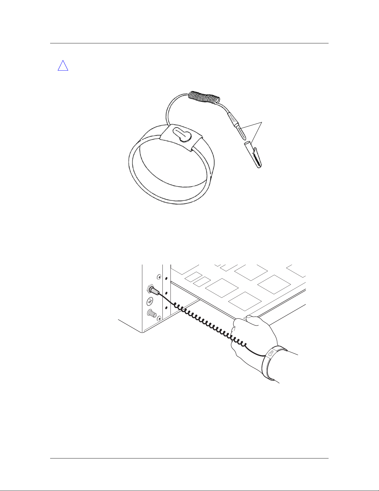
Preparing for the Installation
Preventing static discharge damage
Caution Correct use of an approved antistatic wrist strap is the only reliable way to
!
prevent damage to components by electrostatic discharge from your body
Figure 2-1. Wrist grounding strap
To
ground
connection
To minimize entanglement, right-handed people can wear the strap on the left hand.
Plug the other end of the wrist strap into the grounding jack provided on most Lucent
products, as shown in
Figure 2-2.
Figure 2-2. Wrist strap plugged into a grounding jack
If a grounding jack is not available, use an alligator clip to connect the strap to
electrical ground.
Stinger® MRT Getting Started Guide 2-3
Page 28

Preparing for the Installation
Unpacking the Stinger MRT
Use the following two simple tests to verify that the wrist strap is functioning
properly:
■ Measure the resistance between the wrist strap and its grounding plug. Overall
resistance between these two points must be approximately 1Megohm. If it is
not, replace the strap.
■ Physically examine the strap for visible damage. If you see any damage, replace
the strap.
Remove plastics from your work area
Work areas must be kept clear of common plastics, such as the following items:
■ Polystyrene packing containers
■ Clear plastic bags
■ Plastic drinking cups
■ Food wrappers
■ Clear cellophane tape
These types of common plastic materials can carry a static charge that is not easily
discharged to ground and must not make direct contact with modules or any other
solid state components.
Store components properly
Protect modules immediately after removal from a chassis by placing them in their
original factory packing materials. Storage in approved antistatic packaging is
acceptable when factory packaging is unavailable.
Caution Never place unprotected modules directly on ungrounded metal shelving
!
or on ungrounded carts without insulating surfaces.
Unpacking the Stinger MRT
The Stinger unit is delivered in a protective shipping carton, with the ordered trunk
module installed.
Before you remove the Stinger unit from the shipping carton, check for damage. If
you see any damage, follow the instructions described in your product warranty.
To unpack the unit:
1 Open the carton and remove all enclosed packing materials. Save the packing
materials in case you need to repack the unit later.
2 Carefully remove the unit from the shipping carton.
3 Verify that the contents of the carton match the items listed on the packing slip.
Verifying the hardware configuration
Stinger MRT units have an integrated design that includes a -48Vdc power supply
and all the capabilities associated with control modules, line interface modules
(LIMs), and line protection modules (LPMs) of other Stinger models. Trunk modules
designed for use in a Stinger MRT can be installed to support different types of trunk
2-4 Stinger® MRT Getting Started Guide
Page 29
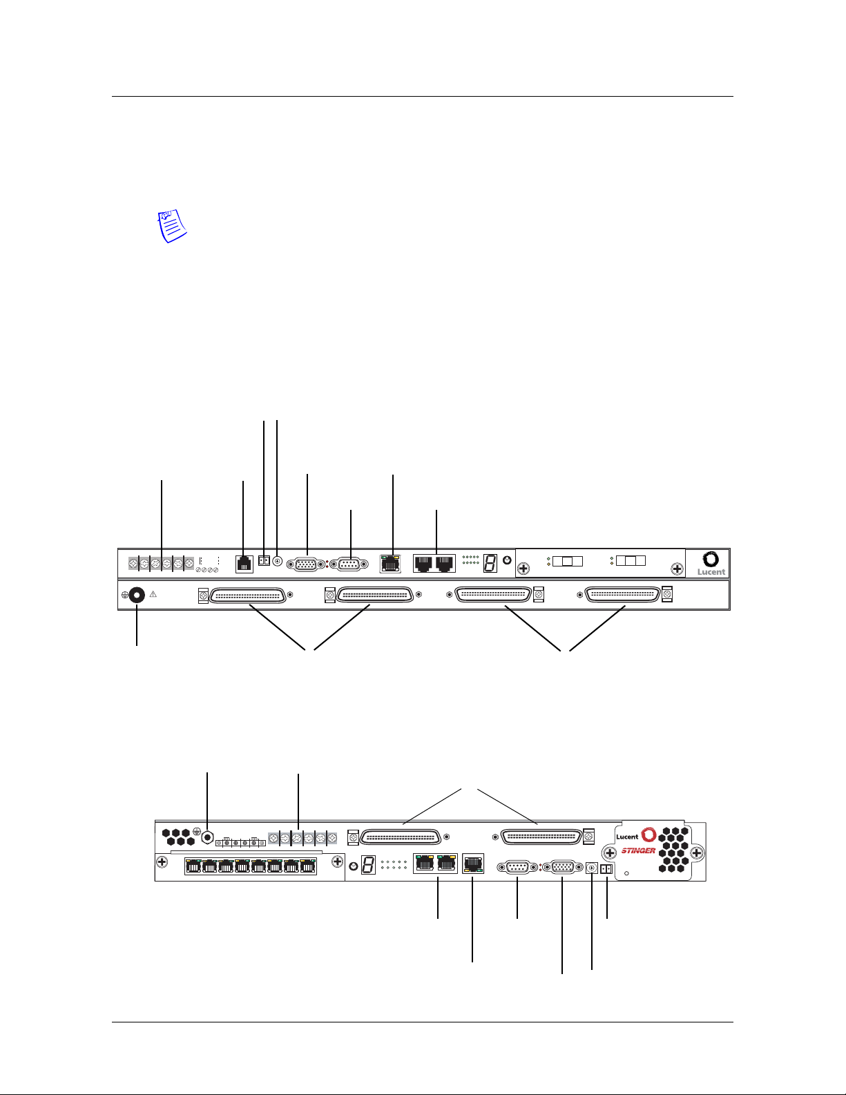
connections. The trunk module ordered with the unit is installed prior to shipment.
Check the unit to verify that it is configured as ordered and to identify the connection
points for power and data. The cable connectors and power supply inlets are located
at the front of the chassis.
Note The system software configuration is stored in onboard nonvolatile RAM
(NVRAM).
Stinger MRT interfaces
Figure 2-3 and Figure 2-4 show the location of all terminals and ports on the Stinger
MRT 23 and Stinger MRT 19 chassis. Trunk port connections, which vary depending
on the trunk module that is installed, are not shown.
Figure 2-3. Stinger MRT 23 chassis connectors
Building integrated
Power
terminals
timing supply
(BITS) connection
Internal
modem
(optional)
Shelf ID
switch
Alarm
connections
Console
connection
Ethernet
STS-3 cascading
connectors
Preparing for the Installation
Verifying the hardware configuration
-48VA
RTN A
LINE 1-24
SEE INSTRUCTION MANUAL
SIEHE ANLEITUNG
LIRE LE MANUEL d'INSTRUCTION
USE OF RING LUGS RECOMMENDED
Grounding terminal
SHELF
POTS
-48VB
RTN B
MODEM
ALARM RELAY
IDBITS
Line connectors (to
LINE 25-48
MINOR
MAJOR
CONSOLE
subscribers)
Figure 2-4. Stinger MRT 19 chassis connectors
Grounding terminal
48V B
PORT 8
Power terminals
RTN
RTN
48V A
B
A
PORT 1
SEL
ETHERNET 10BT
EXP1
EXP2
STATUS
1
610
PORTS
DSL line connections
(to subscribers)
PORTS PORTS
PORT
1
STATUS
GROUP
241
106
5
EXP1
EXP2
10BT
STS-3 cascading
connectors
GROUP
PORT
5
SELECT
POTS connectors
(to POTS switch)
48 25
CONSOLE
Console
connection
MAJOR
MINOR
SD
LOS
POTS 25-48
ALARM
PORT 1
SD
LOS
PORT 2
SHELF
ID BITS
MRT
COOLING
SYSTEM STATUS
Building integrated
timing supply (BITS)
connection
POTS 1-24
Ethernet
Alarm
connections
Shelf ID
switch
Stinger® MRT Getting Started Guide 2-5
Page 30

Preparing for the Installation
Verifying the hardware configuration
STS-3 cascading connectors
Each Stinger MRT and MRT-2 unit is equipped with a pair of STS-3 connectors. These
connectors can connect multiple units that are installed in a single location. The
STS-3 connectors allow creation of ATM links to carry traffic from a Stinger MRT or
MRT-2 unit that is not equipped with a trunk module to a unit that is equipped with
a trunk module. Several units can be linked together so that traffic can be combined
in a cascading fashion, until it reaches a single unit with a line to the distant ATM
switch. This can be managed in two ways.
■ Configured ATM connections—ATM connections can be configured to so that
traffic from all the units is combined in a cascading fashion, until it reaches the
unit with the link to the remote ATM switch.
■ Hosted (master/slave) connections—It is also possible for the unit with the link to
the remote ATM switch to act as the host (master) unit for the other MRT or
MRT-2 units. These other units become hosted (slave) units. All connections
between units are configured automatically by the TAOS software, and all
administration for the group is performed on the TAOS interface of the master
unit. For details about this type of configuration, see
Operation of Cascaded Stinger MRT units.”
Note Lucent Technologies recommends connecting no more than three Stinger MRT
or MRT-2 units in cascading fashion or five units in a hosted system configuration.
Although the units can support longer distances, Lucent recommends that cascading
or hosted units be no more than 10 feet (3.05m) from each other.
Appendix B, “Hosted
Shelf ID switch
The shelf ID switch is used to designate the shelf number that will be associated with
the chassis in a hosted system configuration. See,
on page B-4 for details.
Trunk module location
A Stinger MRT can contain a trunk module that supports OC3/STM1, DS3, T1, or E1
service. Each trunk module supports connection to either optical or copper media,
depending on the type of module supplied. There is a single physical slot on the front
of the Stinger MRT for installation of the trunk module. This slot is referred to by the
operating system as virtual slot
Caution Do not remove or replace the trunk module while the Stinger MRT unit is
!
operating. Be sure to remove power from the unit before removing or replacing a
trunk module.
Note Individual trunk modules are not interchangeable between the Stinger MRT
23 and Stinger MRT 19. For detailed information about a specific trunk module, see
the chapter in this guide related to that module.
Figure 2-5 and Figure 2-6 show the location of the trunk module in the front of a
Stinger MRT 23 and Stinger MRT 19 chassis. An OC3-ATM trunk module is shown
installed.
“Configuring the remote shelves”
18.
2-6 Stinger® MRT Getting Started Guide
Page 31

Figure 2-5. Stinger MRT 23 trunk module location
-48VA
RTN A
LINE 1-24
SEE INSTRUCTION MANUAL
SIEHE ANLEITUNG
LIRE LE MANUEL d'INSTRUCTION
USE OF RING LUGS RECOMMENDED
Grounding terminal
POTS
-48VB
RTN B
MODEM
SHELF
IDBITS
ALARM RELAY
LINE 25-48
MINOR
MAJOR
CONSOLE
ETHERNET 10BT
Figure 2-6. Stinger MRT 19 trunk module location
Grounding terminal
Preparing for the Installation
Verifying the hardware configuration
Trunk module
(slot 18)
STATUS
EXP1
EXP2
GROUP
1
5
610
PORTS
PORT
SELECT
SD
LOS
POTS 25-48
PORT 1
SD
LOS
PORT 2
POTS 1-24
RTN
RTN
48V B
48V A
B
A
PORT 2
LOS
SD
PORT 1
LOS
SD
SEL
Trunk module
(slot 18)
Caution Wear an antistatic wrist strap before handling any of the unit components.
!
For more information, see
OC3/STM1-ATM trunk modules
Figure 2-7 shows the location of the optical fiber connections on an OC3-ATM trunk
module for the Stinger MRT 23 chassis. Figure 2-8 shows the location of the optical
fiber connections on an OC3-ATM trunk module for the Stinger MRT 19 chassis.
PORTS PORTS
PORT
1
STATUS
GROUP
241
106
5
EXP1
EXP2
48 25
10BT
CONSOLE
MAJOR
MINOR
ALARM
SHELF
ID BITS
MRT
COOLING
SYSTEM STATUS
“Preventing static discharge damage” on page 2-2.
Stinger® MRT Getting Started Guide 2-7
Page 32

Preparing for the Installation
Verifying the hardware configuration
Figure 2-7. OC3-ATM trunk module for the MRT 23 chassis
Port 1 Signal IN
Figure 2-8. OC3-ATM trunk module for the MRT 19 chassis
Port 2 Signal OUT
DS3-ATM trunk modules
Figure 2-9 shows the location of the coaxial connections on a DS3-ATM trunk
module for the Stinger MRT 23. Figure 2-9 shows the location of the coaxial
connections on a DS3-ATM trunk module for the Stinger MRT 19.
SD
LOS
PORT 1
Port 1 Signal OUT
PORT 2
Port 2 Signal IN
SD
LOS
Port 2 Signal IN
Port 2 Signal OUT
LOS
SD
Port 1 Signal OUT
Port 1 Signal IN
PORT 2
LOS
SD
PORT 1
2-8 Stinger® MRT Getting Started Guide
Page 33

Figure 2-9. DS3-ATM trunk module for the MRT 23 chassis
Preparing for the Installation
Verifying the hardware configuration
Receive from line
RAI
OF
YEL
LA
Figure 2-10. DS3-ATM trunk module for the MRT 19 chassis
Transmit to line
ACT
ALARM
T1 and E1 trunk modules
AD
BYP
RX RX
PORT
1
TX TX
Transmit to line
PORT 2
Tx Tx
BYP
AD
Rx
Receive from line
Receive from line
RAI
AD
OF
BYP
YEL
LA
Transmit to line
LA
YEL
OF
RAI
PORT
2
Transmit to line
PORT 1
Rx
Receive from line
BYP
AD
ALARM
ACT
LA
YEL
RAI
OF
Figure 2-11 shows the location of the RJ-47 connections on the 8-port T1 or E1 trunk
module for the Stinger MRT 23. The T1 and E1 trunk module for the Stinger MRT 19
is similar (see
Figure 2-12).
Figure 2-11. T1 or E1 trunk module for the MRT 23 chassis
PORT 1
PORT 8
Figure 2-12. T1 or E1 trunk module for the MRT 19 chassis
PORT 8
PORT 1
Stinger® MRT Getting Started Guide 2-9
Page 34

Page 35

Installing a Stinger MRT
3
Before you begin . . . . . . . . . . . . . . . . . . . . . . . . . . . . . . . . . . . . . . . . . . . . . . . . . 3-1
Identifying and installing mounting brackets . . . . . . . . . . . . . . . . . . . . . . . . . . . 3-1
Mounting the MRT in an equipment rack . . . . . . . . . . . . . . . . . . . . . . . . . . . . . . 3-9
Installing and removing trunk modules. . . . . . . . . . . . . . . . . . . . . . . . . . . . . . . 3-12
MRT cooling . . . . . . . . . . . . . . . . . . . . . . . . . . . . . . . . . . . . . . . . . . . . . . . . . . . . 3-13
Replacing the cooling module on the Stinger MRT 19 . . . . . . . . . . . . . . . . . . . 3-14
Connecting cables to a Stinger MRT unit . . . . . . . . . . . . . . . . . . . . . . . . . . . . . . 3-15
Network management connections . . . . . . . . . . . . . . . . . . . . . . . . . . . . . . . . . . 3-23
System clocking . . . . . . . . . . . . . . . . . . . . . . . . . . . . . . . . . . . . . . . . . . . . . . . . . 3-24
Alarm monitoring . . . . . . . . . . . . . . . . . . . . . . . . . . . . . . . . . . . . . . . . . . . . . . . 3-24
Before you begin
Verify that you have completed the following tasks:
■ Selected the installation site
■ Unpacked the Stinger MRT
■ Gathered the tools and equipment needed for installation
■ Verified the trunk module installed in the unit
3-1
3-1
3-9
3-12
3-13
3-14
3-15
3-23
3-24
3-24
Warning Before installing the Stinger MRT hardware, be sure to read the safety
!
instructions in the Edge Access and Broadband Access Safety and Compliance Guide. See
Appendix D, “Safety-Related Electrical, Physical, and Environmental Information”
for information specific to your product.
Identifying and installing mounting brackets
You can rack-mount the Stinger MRT 23 chassis horizontally in an equipment rack or
outdoor cabinet using mounting rails that are 23 inches (58.42cm) apart. You can
mount the Stinger MRT 19 horizontally in equipment racks or outdoor cabinets using
mounting rails that are 23 inches, 19 inches, or 17.72 inches apart (58.42cm,
48.26cm, or 45.0cm).
Stinger® MRT Getting Started Guide 3-1
Page 36
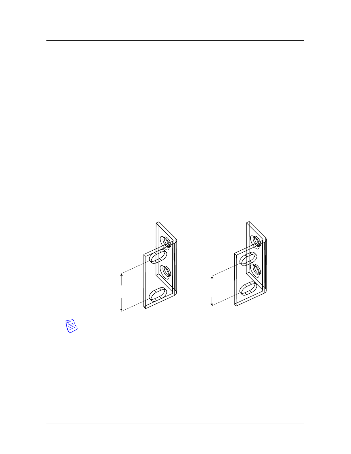
Installing a Stinger MRT
Identifying and installing mounting brackets
Optional mounting hardware is also available for mounting the Stinger MRT 23
chassis vertically between mounting rails spaced 19 inches (48.26cm) apart. The
Stinger MRT 23 and Stinger MRT 19 chassis can also be mounted on a wall, or
positioned on a flat surface as free-standing units. For more information on these
types of installations, contact your Lucent Technologies sales representative.
Mounting brackets for the Stinger MRT 23
Standard mounting brackets and multi-position brackets are available for mounting
the Stinger MRT 23 in 23-inch wide racks with holes spaced 1.252 inches (31.8mm)
or 0.984 inches (25mm) apart.
Standard mounting brackets
The Stinger MRT 23 can be mounted horizontally in a 23-inch wide-rack, using
chassis mounting points at the front or midpoint of the Stinger MRT 23 chassis. Two
paris of mounting brackets and four 8-32 1/4 inch screws are supplied with the
Stinger MRT 23 unit. One pair of brackets has standard vertical spacing of 1.252
inches (31.8mm) between the rack mounting holes. (See
has vertical spacing of 0.894 inch (25mm) between the rack mounting holes to
provide flexibility in racks that have mounting holes with staggered spacing. The
supplied screws are used to attach the brackets to the Stinger MRT 23 chassis.
Figure 3-1) The other pair
Figure 3-1. Stinger MRT 23 mounting brackets
1.252 inches
(31.8mm)
Note The rack-mount spacing meets IEC 297-2 and ANSI/EI ARS-310-C standards.
Multi-position brackets
The multi-position brackets have three pairs of mounting holes that can be aligned
with the front or mid-point mounts on the Stinger MRT 23 chassis. The
multi-position brackets are also known as adjustable brackets, because they allow the
position of the unit to be adjusted forward or backward in the equipment rack. This
allows the Stinger MRT to be positioned to accommodate variable spacing
requirements encountered in outdoor cabinet installations. The brackets can also be
installed in a forward or rear facing position, depending on the desired position of the
chassis.
0.984 inches
(25mm)
3-2 Stinger® MRT Getting Started Guide
Page 37

Installing a Stinger MRT
Identifying and installing mounting brackets
Two pairs of multi-position mounting brackets and four 8-32 1/4 inch screws are
supplied in an optional kit, identified by product code MRT-RM23 (Lucent part
number 0801-0336-001). One pair of brackets has standard vertical spacing of 1.252
inches (31.8mm) between the rack mounting holes. (See
has vertical spacing of 0.894 inch (25mm) between the rack mounting holes to
provide flexibility in racks that have mounting holes with staggered spacing. The
supplied screws are used to attach the brackets to the Stinger MRT 23 chassis.
Figure 3-2. Multi-position mounting brackets
Figure 3-2) The other pair
1.252 inches
(31.8mm)
Warning The weight and position of hardware within the cabinet might make the
!
cabinet top-heavy or unstable. Take all necessary precautions to anchor the cabinet
securely before installing the unit.
0.984 inches
(25mm)
Installing mounting brackets on the Stinger MRT 23
The Standard brackets and the multi-position brackets are attached to the chassis in
the same way. If you are use the multi-position mounting brackets to install the
Stinger MRT, temporarily fit one of the brackets to the mounting rack before
installing the chassis. Hold the chassis within the rack to determine the proper
alignment of the bracket mounting holes, as described in the following procedure.
Determining proper alignment of the multi-position brackets
Use the following procedure to determine the proper alignment of the multi-position
mounting bracket holes with the mounting points on the chassis:
1 Install a mounting bracket on the mounting rail in the position that the Stinger
unit will occupy
2 Manually position the Stinger chassis along side the mounting bracket. Move it
forward or backward to determine which mounting holes on the multi-position
bracket will be used.
Stinger® MRT Getting Started Guide 3-3
Page 38

Installing a Stinger MRT
Identifying and installing mounting brackets
Figure 3-3. Determining the mounting position of the multi-position bracket.
Align mounting
position holes
3 Remove the bracket from the mounting rail, and install it in the next procedure,
using the mounting holes on Stinger chassis that have been identified.
Caution To avoid creating a hazard or damaging the brackets and the Stinger MRT
!
unit, install the chassis so that it is between the mounting rails, and balanced on the
brackets as much as possible. Extreme extension of the chassis from the mounting
rails can create a collision hazard for individuals, and can overstress the mounting
brackets.
Position chassis
LINE 1-24
SEE INSTRUCTION MANUAL
SIEHE ANLEITUNG
LIRE LE MANUEL d'INSTRUCTION
USE OF RING LUGS RECOMMENDED
SHELF
8
7
9
6
0
5
POTS
-48VB
RTN B
RTN A
-48VA
MODEM
1
4
2
3
ID
BITS
Installing the mounting brackets
The Standard brackets and the multi-position brackets are attached to the chassis in
the same way.
To install the mounting brackets onto the unit:
1 Position a mounting bracket onto one side of the Stinger unit, lining up the screw
holes on the bracket with one set of bracket holes on the side of the unit. The
desired bracket holes near the front of the unit or near the midpoint of the unit
can be used, as shown in
Figure 3-4. Installing mounting brackets
Figure 3-4.
Midpoint position
Front position
RTN A
-48VA
E 1-24
LIN
L
A
U
N
A
M
N
IO
T
C
U
R
T
S
N
IN
G
E
IO
N
E
T
U
S
C
IT
U
E
R
L
T
N
S
A
'IN
E
d
H
L
D
IE
E
E
S
U
D
N
N
A
E
M
M
E
M
L
O
E
C
E
IR
L
R
S
G
U
L
G
IN
R
F
O
E
S
U
LE
SO
N
O
C
R
O
IN
M
LAY
E
R
M
ALAR
ELF
SH
8
7
9
6
0
5
TS
O
P
-48VB
RTN B
EM
D
O
M
1
4
2
3
ID
BITS
R
AJO
M
E 25-48
LIN
2 Using a number 2 Phillips screwdriver, install the 1/4-inch flathead screws that
are supplied with the brackets through the mounting bracket holes and into the
unit at either the midpoint or front mounting position, as shown in
Figure 3-4.
3-4 Stinger® MRT Getting Started Guide
Page 39

Installing a Stinger MRT
Identifying and installing mounting brackets
!
Caution Failure to use the proper screws might damage the unit.
3 Repeat step 1 and step 2 to install the second mounting bracket onto the other
side of the unit.
Mounting brackets for the Stinger MRT 19
Mounting brackets are available for installing the Stinger MRT 19 chassis horizontally
in standard 23-inch (58.42cm) racks, 19-inch (48.26cm) EIA Equipment racks, and
ETSI cabinets that have a minimum of 17.72 inches (45.0cm) of space between the
mounting rails.
23-inch mounting brackets for the Stinger MRT 19
The Stinger MRT 19 can be mounted horizontally in a 23-inch rack, using chassis
mounting points at the front and midpoint of the Stinger MRT 19 chassis. Use the
supplied screws to attach the brackets to the Stinger MRT 19 chassis.
Figure 3-5. 23-inch rack mounting brackets for the Stinger MRT 19
0.984 in.
(25mm)
Warning The weight and position of hardware within the cabinet might make the
!
cabinet top-heavy or unstable. Take all necessary precautions to anchor the cabinet
securely before installing the unit.
Installing the 23-inch mounting brackets on the Stinger MRT 19
The 23-inch mounting brackets for the Stinger MRT 19 can be installed to align the
front or mid-point of the chassis with the rails of the 23-inch rack. This is
accomplished by rotating the brackets to position them as shown in
To install the mounting brackets onto the unit:
0.984 in
(25mm)
Figure 3-6.
1 Rotate the brackets to align the front or midpoint of the Stinger MRT 19 chassis
with the mounting rails of the equipment rack, as shown in
Stinger® MRT Getting Started Guide 3-5
Figure 3-6.
Page 40

Installing a Stinger MRT
T
1
T
R
P
Identifying and installing mounting brackets
2 Place a mounting bracket onto one side of the Stinger unit, lining up the four
screw holes on the bracket with the four bracket holes on the side of the unit, as
shown in
Figure 3-6.
Figure 3-6. Installing 23-inch brackets on the Stinger MRT 19
Midpoint
mounting
alignment
Front
mounting
alignment
24
48V A
RTN
RTN
A
48V B
B
LOS
SD
PORT 2
LOS
SD
PORT 1
OUP
R
G
SEL
24
48V A
RTN
RTN
A
48V B
B
LOS
SD
PORT 2
LOS
G
SEL
SD
PORT 1
3 Using a number 2 Phillips screwdriver, install the 1/4-inch flathead screws that
are supplied with the brackets through the mounting bracket holes into the unit,
as shown in
Figure 3-6.
POR
RT
PO
6
1
STATUS
PO
6
1
STA
UP
RO
Caution Failure to use the proper screws may damage the unit.
!
4 Repeat step 1 and step 2 to install the second mounting bracket onto the other
side of the unit.
19-inch ETSI mounting brackets for the Stinger MRT 19
The Stinger MRT 19 can be mounted horizontally in a standard ETSI 19-inch wide
rack, using chassis mounting points at the front or midpoint of the Stinger MRT 19
chassis. Use the supplied screws to attach the brackets to the Stinger MRT 19 chassis.
3-6 Stinger® MRT Getting Started Guide
Page 41

Installing a Stinger MRT
Identifying and installing mounting brackets
Figure 3-7. 19-inch rack mounting brackets for the Stinger MRT 19
0.984 in.
(25mm)
Warning The weight and position of hardware within the cabinet might make the
!
cabinet top-heavy or unstable. Take all necessary precautions to anchor the cabinet
securely before installing the unit.
Installing the 19-inch ETSI mounting brackets on the Stinger MRT 19
The 19-inch mounting brackets for the Stinger MRT 19 can be installed to align the
front or mid-point of the chassis with the rails of the 19-inch rack. This is
accomplished by attaching the brackets to the front or mid-point mounting holes of
the chassis as shown in
To install the mounting brackets onto the unit:
1 Position the brackets to align with the mounting holes at the front or midpoint of
the Stinger MRT 19 chassis.
2 Place a mounting bracket onto one side of the Stinger unit, lining up the two
screw holes on the bracket with two bracket holes on the side of the unit. You
can use bracket holes near the front of the unit or near the midpoint of the unit,
as shown in
Figure 3-8.
Figure 3-8
Stinger® MRT Getting Started Guide 3-7
Page 42

Installing a Stinger MRT
E
Identifying and installing mounting brackets
Figure 3-8. Installing ETSI 19-inch brackets on the MRT 19
3 Using a number 2 Phillips screwdriver, install the 1/4-inch flathead screws
(supplied with the brackets) through the mounting bracket holes into the unit, as
shown in
Figure 3-8.
Midpoint position
Front position
48V A
RTN
RTN
A
48V B
B
LOS
SD
PORT 2
PORT 1
PORTS
1
PORT
10
6
5
1
LOS
SD
STATUS
UP
RO
G
SEL
Caution Failure to use the proper screws might damage the unit.
!
4 Repeat step 1 and step 2 to install the second mounting bracket onto the other
side of the unit.
EIA mounting brackets for the Stinger MRT 19
The Stinger MRT 19 can be mounted horizontally in an EIA rack or enclosure with
mounting rails at least 17.72-inches apart. Mounting points at the front or midpoint
of the Stinger MRT 19 chassis can be used to position the chassis as needed. Use the
supplied screws to attach the brackets to the Stinger MRT 19 chassis.
Figure 3-9. EIA rack mounting brackets for the Stinger MRT 19
1.252 in.
(31.8mm)
Warning The weight and position of hardware within the cabinet might make the
!
cabinet top-heavy or unstable. Take all necessary precautions to anchor the cabinet
securely before installing the unit.
3-8 Stinger® MRT Getting Started Guide
Page 43

Mounting the MRT in an equipment rack
X
Installing the EIA mounting brackets on the Stinger MRT 19
The EIA mounting brackets for the Stinger MRT 19 can be installed to align the front
or the mid-point of the chassis with the rails of the equipment rack. This is
accomplished by attaching the brackets to the front or mid-point mounting holes of
the chassis, as shown in
To install the mounting brackets onto the unit:
1 Position the brackets to align with the mounting holes at the front or midpoint of
the Stinger MRT 19 chassis.
2 Place a mounting bracket onto one side of the Stinger unit, lining up the two
screw holes on the bracket with two bracket holes on the side of the unit. You
can use the bracket holes near the front of the unit or near the midpoint of the
unit, as shown in
Figure 3-10. Installing EIA brackets on the MRT 19
Figure 3-10.
Figure 3-10.
Midpoint position
Installing a Stinger MRT
3 Using a number 2 Phillips screwdriver, install the 1/4-inch flathead screws
(supplied with the brackets) through the mounting bracket holes into the unit, as
shown in
!
Caution Failure to use the proper screws might damage the unit.
Figure 3-10.
4 Repeat step 1 and step 2 to install the second mounting bracket onto the other
side of the unit.
Mounting the MRT in an equipment rack
Once the appropriate mounting brackets have been installed on a Stinger MRT 23 or
Stinger MRT 19 chassis they can be mounted in an equipment rack or cabinet.
Position the unit for installation, keeping in mind that cables connect to the front of
the unit.
Front position
48V A
RTN
RTN
A
48V B
B
LOS
SD
PORT 2
PORT 1
PORTS
24
PORT
10
6
5
E
1
LOS
SD
STATUS
GROUP
SEL
Note The procedure for installing the unit into a cabinet requires that you supply a
minimum of four cross-head screws of the appropriate size to support the unit in the
cabinet rack.
Stinger® MRT Getting Started Guide 3-9
Page 44

Installing a Stinger MRT
Mounting the MRT in an equipment rack
Mounting the Stinger MRT units in a 23-inch rack
To rack-mount a Stinger MRT 23 or Stinger MRT 19 horizontally into a standard
23-inch (58.42cm) equipment rack:
1 Align the screw holes on the mounting bracket with the screw holes on the
equipment rack, as shown in
2 Using a number 2 Phillips screwdriver, install cross-head screws of the
appropriate size through the lower mounting holes of each bracket and into the
equipment rack.
Figure 3-11. Placing Stinger MRT 23 and Stinger MRT 19 chassis in a 23-inch rack
LE
NSO
CO
OR
IN
M
LARM RELAY
A
HELF
S
8
7
9
6
0
5
1
TS
PO
4
2
3
R
AJO
M
ID
-48VB
RTN B
BITS
RTN A
SEE INSTRUCTION MANUAL
SIEHE ANLEITUNG
LIRE LE MANUEL d'INSTRUCTION
USE OF RING LUGS RECOMMENDED
LINE 1-24
-48VA
ODEM
M
LINE 25-48
RNET 10BT
ETHE
Figure 3-11.
POR
UP
RO
G
S
STATU
5
EXP2
1
EXP1
610
TS
POR
SELECT
SD
LOS
RT 2
T
SD
LOS
POR
TS 25-48
PO
PO
T 1
TS 1-24
PO
48
24
S
T
R
O
P
1
T
R
O
P
48V A
RTN
RTN
A
48V B
B
PORT 2
LOS
SD
LOS
PORT 1
SD
10
6
5
1
S
TU
A
T
S
P
U
O
R
G
L
E
S
T
10B
1
XP
E
2
P
X
E
R
AJO
M
M
LAR
A
R
O
IN
M
LE
O
S
N
O
C
MRT
LF
E
H
S
8
7
9
COOLING
6
0
5
1
SYSTEM STATUS
4
2
3
ITS
B
ID
5
2
TS
R
O
P
3 Install and tighten the upper mounting screws.
4 Tighten the lower mounting screws.
Mounting the Stinger MRT 19 in smaller equipment racks
The Stinger MRT 19 can be mounted horizontally in a 19-inch wide-rack, using the
ETSI mounting brackets, or in a 17.72-inch wide-rack, using the EIA mounting
brackets. Use the supplied screws to attach the brackets to the Stinger MRT 19
chassis.
The procedure for mounting a Stinger MRT 19 in either of these smaller racks is
similar to the procedure for mounting the unit in the larger 23-inch rack. To
rack-mount a Stinger MRT 19 horizontally into a standard 19-inch or 17.72-inch
equipment rack:
1 Align the screw holes on the mounting bracket with the screw holes on the
equipment rack, as shown in
Figure 3-12.
3-10 Stinger® MRT Getting Started Guide
Page 45

2 Using a number 2 Phillips screwdriver, install cross-head screws of the
appropriate size through the lower mount holes of each bracket and into the
equipment rack.
Figure 3-12. Placing Stinger MRT 19 chassis in a smaller equipment rack
48
1
PORTS
24
PORT
A
V
8
N
4
T
R
N
T
R
A
B
V
8
4
B
PORT 2
LOS
SD
LOS
PORT 1
SD
10
6
5
EXP2
1
STATUS
GROUP
SEL
CONSOLE
10BT
EXP1
Installing a Stinger MRT
Mounting the MRT in an equipment rack
25
PORTS
MAJOR
ALARM
MINOR
RT
M
SHELF
G
8
IN
7
L
9
O
O
C
S
6
U
T
A
0
T
S
M
5
E
1
T
S
Y
S
4
2
3
BITS
ID
Mounting in a 19-inch rack
48
1
PORTS
24
PORT
A
V
8
N
4
T
R
N
T
R
A
B
V
8
4
B
PORT 2
LOS
SD
LOS
PORT 1
SD
10
6
EXP1
5
EXP2
1
STATUS
GROUP
SEL
MAJOR
ALARM
MINOR
CONSOLE
10BT
T
R
M
SHELF
G
8
IN
7
L
9
O
O
C
S
6
U
T
A
0
T
S
M
5
E
1
T
S
Y
S
4
2
3
BITS
ID
25
PORTS
Mounting in a 17.72-inch rack
3 Install and tighten the upper mounting screws.
4 Tighten the lower mounting screws.
Stinger® MRT Getting Started Guide 3-11
Page 46

Installing a Stinger MRT
Installing and removing trunk modules
Warning The weight and position of hardware within the cabinet might make the
!
cabinet top-heavy or unstable. Take all necessary precautions to anchor the cabinet
securely before installing the unit.
Installing and removing trunk modules
A Stinger MRT trunk module can be replaced for maintenance purposes, or to change
the type of outbound (egress) line used by the unit. Trunk modules for the MRT 23
and MRT 19 are slightly different, and are not interchangeable. When changing trunk
modules, be sure that you use a trunk module that is designed for your MRT chassis.
Caution Wear an antistatic wrist strap before handling any of the unit components.
!
For more information, see
Warning If power to the unit is not turned off, an electrical energy hazard is present
within the card cage. Remove all metallic objects from hands and wrist to prevent
bridging of live contact points.
Installing a trunk module
To install a trunk module:
“Preventing static discharge damage” on page 2-2.
1 Put on the antistatic wrist strap and connect it to ground potential.
2 Verify that power to the Stinger MRT unit has been disconnected or turned off.
3 For the MRT 23, turn the trunk module so the connector is below the printed
circuit board, and the circuit board is aligned to slide above the guide rails in the
top of the trunk module slot, as shown in
Figure 3-13.
Figure 3-13. Installing an MRT 23 trunk module
STATUS
GROUP
1
610
PORTS
PORT
5
SELECT
POTS 25-48
LOS
SD
POTS 1-24
PORT 1
SD
LOS
PORT 2
For the MRT 19, turn the trunk module so that the connector is above the
printed circuit board, and the circuit board is aligned to slide into the guide track
near the bottom of the trunk module slot, as shown in
Figure 3-14.
3-12 Stinger® MRT Getting Started Guide
Page 47

Installing a Stinger MRT
S
PO
MRT cooling
Figure 3-14. Installing an MRT 19 trunk module
1
T
POR
A
V
8
N
4
T
R
N
RT
A
B
V
48
B
GROUP
SEL
10
6
5
XP2
E
1
STATUS
PORT 2
10BT
XP1
E
LOS
SD
PORT 1
MAJOR
ALARM
INOR
M
LE
SO
ON
C
LOS
SD
4 Slide the trunk module into the trunk module slot until the connector on the
module comes in contact with the connector within the chassis. Do not force the
card into the slot.
5 Firmly press the module completely into the slot to engage the connector on the
card with the connector in the chassis.
6 Using a number 2 Phillips screwdriver, carefully tighten both screws on the trunk
module. Do not overtighten.
Removing a trunk module
To remove a trunk module:
1 Put on the antistatic wrist strap and connect it to ground potential.
2 Disconnect or turn off power to the unit.
3 Using a number 2 Phillips screwdriver, loosen the thumbscrews located on both
sides of the trunk module, shown in
damage the screw heads.
4 Grasp the thumb screws firmly and pull the trunk module clear of its connector
within the chassis.
5 Carefully slide the trunk module out of the chassis, and place it into an antistatic
container.
MRT cooling
Fans used for cooling the Stinger MRT 19 are housed in a replaceable cooling module
(PN
0710-1053-001). If a fan in the Stinger MRT 19 cooling module fails, the cooling
module can be replaced while the Stinger unit is in service.
Caution To avoid overheating, the cooling module must not be removed from an
!
operating MRT 19 unit for more than two minutes.
You can monitor fan status remotely in both the Stinger MRT 23 and the Stinger
MRT 19 by creating an alarm profile, as described in the Stinger Administration Guide.
Figure 3-13. Other screwdrivers might
Stinger® MRT Getting Started Guide 3-13
Page 48

Installing a Stinger MRT
Replacing the cooling module on the Stinger MRT 19
Caution 50-pin connectors used on the Stinger MRT 19 must have cables that
!
extend from the left side of the connectors. These cables must be routed to the left
side of the chassis to avoid blocking air-flow from the cooling module.
Fans used for cooling the MRT 23 are not field replaceable.
Replacing the cooling module on the Stinger MRT 19
Use the following procedure to replace the cooling module on a Stinger MRT 19.
1 Put on the antistatic wrist strap and connect it to ground potential.
2 Loosen the locking screws on both sides of the old cooling module and pull old
cooling module from the chassis, as shown in
Figure 3-15. Removing the cooling module of a Stinger MRT 19
Figure
Cooling module lock screws
ALARM
25
SHELF
8
7
9
6
0
5
1
4
2
3
BITS
ID
MRT
OLING
CO
STATUS
SYSTEM
10BT
48
CONSOLE
AJOR
M
MINOR
PORTS
3 Align the slot on the bottom of the new cooling module with the alignment studs
inside the bottom of the Stinger MRT 19 chassis and slide new cooling module
straight into the Stinger MRT chassis, as shown in
Figure 3-16.
4 Firmly press the module completely into the chassis to engage the power
connector on the module with the connector in the chassis.
3-14 Stinger® MRT Getting Started Guide
Page 49

Figure 3-16. Installing a replacement cooling module
Cooling module alignment slot
Installing a Stinger MRT
Connecting cables to a Stinger MRT unit
MRT
COOLING
SYSTEM STATUS
ALARM
25
SHELF
8
7
9
6
0
5
1
4
2
3
BITS
ID
4
ROUP
6
1
PORT
STATUS
PORTS
1
10
5
EXP2
EXP1
10BT
48
CONSOLE
PORTS
MAJOR
MINOR
Chassis alignment studs
5 Firmly press the module completely into the slot to engage the connector on the
module with the connector in the chassis.
6 Using a number 2 Phillips screwdriver, carefully tighten the locking screws on the
cooling module. Do not overtighten.
Connecting cables to a Stinger MRT unit
Once the Stinger MRT is set up in the desired location, connect the unit to the local
subscriber lines or to its frame access point by attaching the appropriate cables to the
50-pin RJ-21 LINE connectors. For cable pinouts, see
connections” on page C-4.
Stinger® MRT Getting Started Guide 3-15
“Pinouts for subscriber line DSL
Page 50

Installing a Stinger MRT
Connecting cables to a Stinger MRT unit
With the proper equipment, you can also make the following additional connections:
■ For voice service, connect the unit to the voice switch or its frame access point by
attaching the appropriate cables to the 50-pin POTS connectors. For cable
pinouts, see
■ Connect the Stinger to the ATM network by attaching the copper or fiber
“Pinouts for POTS connections to a voice switch” on page C-7.
connections to the trunk module.
■ To connect a serial cable to the unit’s CONSOLE port for initial configuration, see
“Making the initial administrative connection” on page 6-2.
■ Some Stinger MRT units (model MRT-AD-36S-56K) have an internal analog
modem that supports dial-in administrative connections. To connect an analog
POTS line to the internal modem, see
modem” on page 6-12.
■ To connect an external modem to the unit’s CONSOLE port for administrative
use, see
“Connecting to and configuring an external modem” on page 6-11.
50-pin connectors details
50-pin connectors are used on the Stinger MRT chassis to provide connections for
subscriber DSL lines and POTS connections to the voice switch. These 50-pin
connectors can be secured to the chassis by three mechanisms shown in
It is recommended that you use these mechanisms to make the connectors as secure
as posible.
“Connecting to and configuring an internal
Figure 3-17.
■ An anchor screw on the far end of the connector can be screwed into a fitting on
the chassis.
■ A locking tab under the cable side of the connector automatically secures the
connector upon installation.
■ A nylon cinch-tie can be used secure the cable end of the connector to a tie-down
fitting on the chassis. If the connectors you are using have a slot to accept the
connector locking tab, use of a nylon cinch-tie is optional.
Figure 3-17. 50-pin connector security mechanisms
Anchor
screw
Locking tab
Locking tab slot
Cinch-tie
Connecting the subscriber lines
To connect the cables to the line ports of the Stinger MRT:
3-16 Stinger® MRT Getting Started Guide
Page 51

Installing a Stinger MRT
Connecting cables to a Stinger MRT unit
1 Carefully insert the 50-pin RJ-21 connectors of the subscriber line cables on the
line connectors of the Stinger MRT chassis, as shown in
Figure 3-18 on page
3-17.
2 Push the cable connectors onto the chassis connectors until each locking tab is
engaged.
3 Tighten the anchor screw on each cable connector.
4 Secure the cable connectors to the chassis with a cable tie around the connectors
and through the security fixtures on the left side of the line connectors on the
chassis. (Optional, if your cable connectors have a slot to engage the locking tab.)
Figure 3-18. Connecting the subscriber lines to the Stinger MRT 23
-48VA
LINE 1-24
SEE INSTRUCTION MANUAL
SIEHE ANLEITUNG
LIRE LE MANUEL d'INSTRUCTION
USE OF RING LUGS RECOMMENDED
LINE 1-24
SEE INSTRUCTION MANUAL
SIEHE ANLEITUNG
LIRE LE MANUEL d'INSTRUCTION
USE OF RING LUGS RECOMMENDED
POTS
-48VB
-48VA
RTN B
RTN A
MODEM
Secure with cable ties
POTS
-48VB
RTN B
MODEM
SHELF
SHELF
IDBITS
MINOR
ALARM RELAY
IDBITS
MAJOR
LINE 25-48
MINORALARM RELAY
LINE 25-48
Tighten anchor screws
CONSOLE
CONSOLE
ETHERNET 10BT
ETHERNET 10BT
EXP2
EXP2
STATUS
GROUP
1
5
610
PORTS
STATUS
GROUP
1
5
610
PORTS
PORT
SELECT
PORT
SELECT
SD
LOS
SD
LOS
PORT 1
POTS 25-48
PORT 1
POTS 25-48
EXP1
EXP1
Stinger® MRT Getting Started Guide 3-17
Page 52

Installing a Stinger MRT
Connecting cables to a Stinger MRT unit
Figure 3-19. Connecting the subscriber lines to the Stinger MRT 19
RTN
RTN
48V B
48V A
B
A
PORT 1
PORT 1
LOS
SD
LOS
SD
LOS
SD
T 2
RTN
RTN
48V B
48V A
B
A
LOS
SD
2
Caution Cables from the 50-pin connectors on the Stinger MRT 19 must be routed
!
to the left to avoid blocking air flow from the cooling module.
Connecting the POTS lines
24
PORTS PORTS
PORT
106
5
1
STATUS
GROUP
SEL
Secure with cable ties
24
PORTS PORTS
PORT
106
5
1
STATUS
GROUP
SEL
EXP2
EXP2
1
EXP1
10BT
1
EXP1
10BT
Tighten anchor screws
48 25
MAJOR
MINOR
MAJOR
MINOR
ALARM
ALARM
CONSOLE
48 25
CONSOLE
SHELF
ID BITS
SHELF
ID BITS
MRT
COOLING
SYSTEM STATUS
MRT
COOLING
SYSTEM STATUS
To connect the cables to the POTS ports of the Stinger MRT:
1 Carefully insert the 50-pin RJ-21 connectors of the cables from the POTS switch
on the POTS connectors of the Stinger MRT chassis, as shown in
Figure 3-20 on
page 3-19.
2 Push the cable connectors onto the chassis connectors until each locking tab is
engaged.
3 Tighten the anchor screw on each cable connector.
4 Secure the cable connectors to the chassis with a cable tie around the connectors
and through the security fixtures on the left side of the line connectors on the
chassis. (Optional, if your cable connectors have slots to engage the locking tabs.)
3-18 Stinger® MRT Getting Started Guide
Page 53

Figure 3-20. Connecting the POTS lines
EXP1
ELF
LF
ALARM RELAY
LINE 25-48
ALARM RELAY
LINE 25-48
MINOR
MAJOR
MINOR
MAJOR
CONSOLE
CONSOLE
ETHERNET 10BT
ETHERNET 10BT
EXP2
1
610
EXP2
STATUS
1
610
EXP1
STATUS
PORTS
PORTS
Installing a Stinger MRT
Connecting cables to a Stinger MRT unit
GROUP
PORT
5
SELECT
SD
LOS
PORT 1
POTS 25-48
Secure with cable ties
GROUP
ID
5
SELECT
SD
LOS
PORT 1
POTS 25-48
SD
LOS
PORT 2
POTS 1-24
SD
LOS
PORT 2
POTS 1-24
Tighten anchor screws
Disconnecting a 50-pin connector
The locking tab on the 50-pin connectors used on the Stinger MRT make these
connectors less likely to become loose during operation. However, these tabs require
additional attention when disconnecting the 50-pin connectors from the Stinger
chassis.
Lucent Technologies recommends that you use the tip of a small probe or small
screwdriver to disengage the latch when removing a 50-pin connector as described
in,
“Recommended method to disconnect a 50-pin connector.” However, if no such
tool is available, the connector can be removed by gently rocking the opposite end of
the connector away from the chassis and pulling as described in,
to disconnect a 50-pin connector.”
Recommended method to disconnect a 50-pin connector
To remove a 50-pin connector from the Stinger MRT chassis perform the following
steps:
1 Completely loosen the anchor screw on the connector
2 Using a small pair of diagonal cutters, cut the nylon tie-down strap, if equipped.
3 Depress the connector latch with a small probe or screwdriver, while gently
pulling the connector away from the chassis, as shown in
“Alternate method
Figure 3-21.
Stinger® MRT Getting Started Guide 3-19
Page 54

Installing a Stinger MRT
Connecting cables to a Stinger MRT unit
Figure 3-21. Removing the 50-pin connector (recommended method)
Alternate method to disconnect a 50-pin connector
If a probe, small screwdriver, or similar tool is not available to disengage the
connector latch, the 50-pin connector may be removed by carefully performing the
following steps:
1 Completely loosen the anchor screw on the connector
2 Using a small pair of diagonal cutters, cut the nylon tie-down strap.
3 Carefully rock the anchor screw away from the chassis slightly and pull the
connector away from the chassis in a diagonal direction away from the anchor
screw, as show in
Caution Use care when rocking the connector. Forcing the anchor screw away from
!
the chassis at too great an angle can crack the 50-pin connector.
Figure 3-22. Removing the 50-pin connector (alternate method)
Figure 3-22.
Connecting the STS-3 cascading connections
Each Stinger MRT unit is equipped with a pair of STS-3 connectors. These connectors
are labeled and function the same on the Stinger MRT 23 and Stinger MRT 19,
3-20 Stinger® MRT Getting Started Guide
Page 55

Installing a Stinger MRT
3
7
Connecting cables to a Stinger MRT unit
although they are in slightly different locations, as shown in Figure 2-3 and Figure
2-4 on page 2-5.
The STS-3 connectors can be used with Category 5 unshielded twisted pair (UTP)
cable to connect multiple Stinger MRT or MRT-2 units together that are installed in a
single location. Traffic from the multiple units can be combined for transmission
through a single link from one of the units to a remote ATM switch. This can be
managed in two ways.
■ Configured ATM connections—ATM connections can be configured so that traffic
from all the units is combined in a cascading fashion, until it reaches the unit
with the link to the remote ATM switch.
■ Hosted (master/slave) connections—It is also possible for the unit with the link to
the remote ATM switch to act as the host (master) unit for the other MRT or
MRT-2 units. These other units become hosted (slave) units. All connections
between units are configured automatically by the TAOS software, and all
administration for the group is performed on the TAOS interface of the master
unit. For details about this type of configuration, see
Appendix B, “Hosted
Operation of Cascaded Stinger MRT units.”
The STS-3 ports are labeled EXP1 and EXP2. Both ports have identical capabilities,
and can be used interchangeably for unit-to-unit connections. To avoid confusion
Lucent recommends that you adopt a consistent physical protocol for connecting the
units. For example, in
Figure 3-23 on page 3-21, the EXP2 connector of one Stinger
MRT unit connects to the EXP1 connector of the next unit in sequence. The EXP1
and EXP2 connectors are connected by turnover cables, terminated with RJ-45
connectors. For connector details, see
“STS-3 (synchronous transport signals-3)
connector specifications” on page C-3.
Figure 3-23. Connecting the STS-3 cascading connection
SD
LOS
ETHERNET 10BT
CONSOLE
MINOR
ALARM RELAY
SHELF
8
7
9
6
0
5
1
4
2
3
MAJOR
ID
LINE 25-48
ETHERNET 10BT
CONSOLE
MINOR
ALARM RELAY
SHELF
8
7
9
6
0
5
1
4
2
3
MAJOR
ID
LINE 25-48
ETHERNET 10BT
CONSOLE
MINOR
ALARM RELAY
ELF
8
9
0
1
2
MAJOR
D
LINE 25-48
6
PORTS
STATUS
EXP2
1
EXP1
6
PORTS
STATUS
5
EXP2
1
EXP1
0
1
6
PORTS
POTS 25-48
SD
ID
GROUP
LOS
5
0
1
SELECT
POTS 25-48
SD
ID
GROUP
LOS
SELECT
POTS 25-48
SD
ID
GROUP
LOS
STATUS
5
EXP2
1
EXP1
0
1
SELECT
PORT 2
SD
PORT 2
PORT 2
POTS 1-24
POTS 1-24
ETHERNET 10BT
POTS 1-24
EXP1
EXP2
STATUS
1
6
PORTS
5
10
SELECT
LIN
P
PORT 1
LOS
PORT 1
SOLE
SD
LOS
PORT 1
STS-3 from
other Stinger MRT
Stinger® MRT Getting Started Guide 3-21
Page 56

Installing a Stinger MRT
Connecting cables to a Stinger MRT unit
Although the STS interfaces are permanently installed in the MRT chassis, the TAOS
software addresses them as slot 17 to maintain command-line-interface consistency
with other Stinger models.
Connecting the trunk module
The trunk module cables are either coaxial (for DS3), shielded dual pair with RJ-48
connectors (for T1 or E1), or fiber optic (for OC-3/STM-1 optical).
For additional details about configuring the trunk modules, see the chapter in this
guide that deals with the appropriate trunk module.
Inform your service provider that the equipment is connected, so the provider can
enable the line.
OC3/STM1-ATM trunk module connections
An OC3-ATM trunk module requires duplex SC fiber optic cable. The following
illustration shows the trunk module for the Stinger MRT 23 to illustrate this type of
connection. Physical ports on the trunk module for the Stinger MRT 19 are
positioned and labeled in reverse order, from left to right, see
2-8 on page 2-8 for details.
Figure 2-7 and Figure
Caution If excess fiber optic cable is found at the location of the Stinger MRT, bind
!
the excess cable length in a figure-eight pattern. Do not wind excess cable into
circular coils.
To connect the cables to an OC3-ATM trunk module, align the small rectangular key
on the head of the cable connector with the slot in the connector on the trunk
module and carefully insert the head of each cable into the proper connector on the
trunk module. See
Note Clean any fiber optic cables prior to connecting them.
Figure 3-24.
Figure 3-24. Connecting an OC3-ATM trunk module
SD
LOS
DS3-ATM trunk module connections
PORT 1
SD
LOS
PORT 2
Connect the DS3 line to the RX LN and TX LN connectors on a DS3-ATM trunk
module, using two 75-ohm coaxial cables (RG 59/U), as shown in
Figure 3-25. The
illustration shows the trunk module for the Stinger MRT 23 to illustrate this type of
connection. Physical ports on the trunk module for the Stinger MRT 19 are
positioned and labeled in reverse order, from left to right, see
Figure 2-9 and Figure
2-10 on page 2-9 for details.
3-22 Stinger® MRT Getting Started Guide
Page 57

Figure 3-25. Connecting DS3-ATM trunk modules
RAI
AD
OF
BYP
YEL
LA
RAI
AD
OF
BYP
YEL
LA
RX RX
PORT
1
RX RX
PORT
1
TX TX
OF
YEL
TX TX
OF
YEL
Installing a Stinger MRT
Network management connections
RAI
AD
PORT
PORT
2
2
BYP
LA
RAI
AD
BYP
LA
ALARM
ACT
ALARM
ACT
T1 or E1 trunk module connections
The T1 or E1 trunk module uses standard dual shielded pair cabling, terminated with
RJ-48 connectors. The following illustration shows the trunk module for the Stinger
MRT 23 to illustrate this type of connection. Physical ports on the trunk module for
the Stinger MRT 19 are positioned and labeled in reverse order, from left to right, see
Figure 2-11 and Figure 2-12 on page 2-9 for details.
Connect the cables to a T1 or E1 trunk module by aligning the clip on the RJ-48
connector of the cable with the clip slot of the trunk module port and carefully
inserting the connector into the proper port on the trunk module, as shown in
Figure 3-26.
Figure 3-26. Connecting a T1 or E1 trunk module
PORT 1
Network management connections
PORT 8
The Stinger MRT can support three types of network management connections for
communication with the unit:
Stinger® MRT Getting Started Guide 3-23
Page 58

Installing a Stinger MRT
System clocking
■ Serial connection of a console terminal to the female DB-9 serial port (labeled
CONSOLE) on the chassis, by an RS-232 shielded straight-through cable. For
details, see
■ Dial-in connection through a modem.
– An external modem can be connected to the serial (CONSOLE) connection of
the Stinger MRT with an RS-232 shielded crossover cable. For details, see
“Connecting to and configuring an external modem” on page 6-11.
– The model MRT-AD-36S-56K chassis is equipped with an internal
autoanswer modem that can be connected directly to a telephone line via the
RJ-11 jack labeled MODEM. For details, see
an internal modem” on page 6-12.
■ Network connection through an Ethernet network via the Ethernet RJ-45
interface on the unit, by a 10BaseT unshielded twisted pair (UTP) cable. For
details, see
See Appendix C, “Cables and Connectors” for details about cable pinouts.
System clocking
“Making the initial administrative connection” on page 6-2.
“Connecting to and configuring
“Connecting to an Ethernet LAN” on page 6-10.
A Stinger MRT has three possible timing sources:
■ External. The Stinger MRT can accept timing from a T1 line, or a building
integrated timing supply (BITS) clock.
■ Trunk. The unit can accept timing from an OC3 or DS3 line clock.
■ Internal clock source. If the selected clock sources fail, the system is automatically
reconfigured so that it is synchronized with the internal clock.
The T1 or BITS timing inputs work with DS1 timing references that comply with the
ANSI T1.102 standard. The system timing is configured via the TAOS command line
interface.
Alarm monitoring
The ALARM RELAY connector has outputs that allow a Stinger MRT to be monitored
remotely by another device. This connector also has inputs that allow a Stinger MRT
to perform remote monitoring of up to four other devices.
Connecting to monitor Stinger MRT alarm status
A Stinger MRT unit can monitor itself for major and minor alarm conditions and
illuminate appropriate status lights on the chassis. In addition, you can connect audio
and visual alarms (normally open, or normally closed) to monitor the unit remotely
for these conditions.
Alarm relays operate during loss of power, during hardware failure, or whenever a
Stinger MRT is being reset, such as during its power-on self test (POST). During
normal operation, the alarm relays remain idle.
The gauge of the wire you use to connect to the Stinger MRT alarm relay must be
based on the current flow of the circuit that the relay is attached to and the capacity
of the alarm relay. Because the Stinger alarm relay can carry a maximum of 2 amps,
18 AWG to 20 AWG (0.8mm² to 0.5mm²) wire is adequate.
3-24 Stinger® MRT Getting Started Guide
Page 59

Installing a Stinger MRT
Alarm monitoring
To connect a remote alarm indicator, use a male DB-15 connector to attach a 15-lead
cable to the ALARM RELAY connector of the Stinger MRT unit. Then attach wire
from the pins of the DB-15 connector to the remote indicator according to
Table 3-1. Alarm connector pinouts for Stinger MRT alarms
DB-15 connector pin Function
Pin 1 Alarm relay 1: normally closed
Pin 2 Alarm relay 1: common
Pin 3 Alarm relay 1: normally open
Pin 4 Alarm relay 2: normally closed
Pin 5 Alarm relay 2: common
Pin 6 Alarm relay 2: normally open
For information about defining and maintaining alarms to monitor the Stinger MRT
unit, see the Stinger Administration Guide.
Table 3-1.
Connecting a Stinger MRT to monitor the alarm status of other devices
The connection to each external device consists of a pair of 24-to-28-gauge wires.
One wire supplies ground, and the other monitors the alarm status of the remote
device by applying 3.3Vdc, which draws less than 10mA of current through the
closed contacts of the alarm relay on the remote device. For a complete listing of the
pinout arrangement of all alarm connectors on the DB-15 connector, see
connector pinouts” on page C-2.
To monitor a remote device, use a male DB-15 connector to attach a 15-lead cable to
the ALARM RELAY connector of a Stinger MRT unit. Then attach wire from the pins
of the DB-15 connector to the remote devices that will be monitored, according to
Table 3-2.
Table 3-2. Alarm connector pinouts for monitoring the alarm status of remote devices
DB-15 connector pin Function
Pin 7 Status relay 3
Pin 8 Ground
Pin 9 Not used
Pin 10 Status relay 4
“Alarm
Pin 11 Ground
Pin 12 Status relay 5
Pin 13 Ground
Stinger® MRT Getting Started Guide 3-25
Page 60

Installing a Stinger MRT
Alarm monitoring
Table 3-2. Alarm connector pinouts for monitoring the alarm status of remote devices
DB-15 connector pin Function
Pin 14 Status relay 6
Pin 15 Ground
The alarm relays of external devices can be either normally opened or normally
closed. A Stinger MRT unit can be configured to report an alarm condition for the
opening of a normally closed relay, or the closing of a normally open relay. For
information on defining and administering alarms to monitor remote devices, see the
Stinger Administration Guide.
3-26 Stinger® MRT Getting Started Guide
Page 61

Determining the Operating Status
4
Before you begin . . . . . . . . . . . . . . . . . . . . . . . . . . . . . . . . . . . . . . . . . . . . . . . . . 4-1
Power requirements . . . . . . . . . . . . . . . . . . . . . . . . . . . . . . . . . . . . . . . . . . . . . . . 4-1
Connecting power to a Stinger MRT unit . . . . . . . . . . . . . . . . . . . . . . . . . . . . . . 4-2
Monitoring backup power to a Stinger MRT . . . . . . . . . . . . . . . . . . . . . . . . . . . . 4-3
Turning on power to a Stinger MRT unit . . . . . . . . . . . . . . . . . . . . . . . . . . . . . . . 4-4
Turning off power to a Stinger MRT unit . . . . . . . . . . . . . . . . . . . . . . . . . . . . . . . 4-4
Status lights . . . . . . . . . . . . . . . . . . . . . . . . . . . . . . . . . . . . . . . . . . . . . . . . . . . . . 4-4
Monitoring the status of the DSL ports . . . . . . . . . . . . . . . . . . . . . . . . . . . . . . . . 4-7
Before you begin
Before you begin, verify that the following tasks are complete:
■ Set up the Stinger MRT hardware (as either a free-standing, rack-mounted, or
wall-mounted unit)
■ Connected cables and console terminal to the Stinger MRT
■ Set up the workstation to configure the Stinger MRT
■ Connected the workstation to the Stinger MRT
■ (Optional) Connected the system clock source
■ (Optional) Connected the remote alarms
4-1
4-1
4-2
4-3
4-4
4-4
4-4
4-7
Power requirements
The Stinger MRT operates on -48Vdc. It has two pair of power input terminals that
allow it to be connected to redundant power sources. The Stinger MRT units have a
maximum power requirement of 150 watts. The dc power source for the Stinger
MRT must be protected by a 5-amp fuse. For model-specific details, see
page D-1.
Stinger® MRT Getting Started Guide 4-1
Table D-1 on
D-1
Page 62

Determining the Operating Status
Connecting power to a Stinger MRT unit
Connecting power to a Stinger MRT unit
Caution Before connecting power, see the Edge Access and Broadband Access Safety and
!
!
Compliance Guide for safety instructions and circuit regulatory information.
Warning Verify that the power is off or disconnected at the source before beginning
this procedure.
To connect the unit to dc power:
1 Verify that the correct power source is available for the Stinger MRT.
Caution The -48Vdc power source must include a double pole circuit breaker to
provide a method of disconnecting the unit from power, as required by national
and international safety standards UL 1950 and IEC/EN60950.
2 Verify that the dc power cables comply with national standards and specifications
as described in IEC 60950 and are terminated in number 10 ring lugs.
Note Minimum wire size for up to 6A is 0.75mm² or 18 AWG
3 Locate the power terminal strip on the front of the unit and remove the plastic
shield by squeezing the clips on each side of the shield and pulling the shield
away from the unit, as shown
Figure 4-1.
Figure 4-1. Removing the power terminal shield of a Stinger MRT 23
MINOR
MAJOR
LINE 25-48
-48VA
RTN A
LINE 1-24
ANUAL
SEE INSTRUCTION M
SIEHE ANLEITUNG
ANUEL d'INSTRUCTION
LIRE LE M
USE OF RING LUGS RECOMMENDED
-48VB
RTN B
POTS
MODEM
BITS
SHELF
7
6
5
4
3
ID
8
9
0
1
2
ALARM RELAY
Note Although the location of the power terminal strip is slightly different on the
front of the Stinger MRT 19 chassis, the protective plastic shield is removed in the
same manner.
4 Using Figure 4-2 or Figure 4-3 as a guide (depending on model), attach a power
cable to each set of power connectors as follows. Both power cables must be
connected at all times when the unit is in operation.
– Using a number 2 Phillips screwdriver, remove the screws for the -48Vdc and
return connections.
– Insert one screw into each of the ring lugs on the power leads.
– Reinstall each screw with its power lead onto the appropriate power terminal
position.
C
Note You can ground the chassis to the enclosure by attaching a grounding
cable to the ground terminal on the front of the unit.
4-2 Stinger® MRT Getting Started Guide
Page 63

Determining the Operating Status
T
Monitoring backup power to a Stinger MRT
Figure 4-2. Connecting the -48Vdc power filters on the MRT 23
-48 Vdc inputs
A B
POTS
-48VB
-48VA
RTN B
RTN A
MODEM
LINE 1-24
SEE INSTRUCTION MANUAL
SIEHE ANLEITUNG
LIRE LE MANUEL d'INSTRUCTION
Ground terminal
USE OF RING LUGS RECOMMENDED
A B
Return connections
Figure 4-3. Connecting the -48Vdc power filters on the MRT 19
Return connections
B A
Ground terminal
-48 VDC input B
PORT 8
RTN
RTN
48V B
48V A
B
A
PORT 1
SEL
SHELF
IDBITS
ALARM RELAY
MINOR
MAJOR
LINE 25-48
-48 Vdc input A
24 1
PORTS
PORT
106
5
1
STATUS
GROUP
EXP2
CONSOLE
EXP1
ETHERNE
10BT
5 Replace the power terminal shield by pressing it onto the two clips at each end of
the power terminal strip until they latch to hold the shield in place.
Monitoring backup power to a Stinger MRT
The power input components of the Stinger MRT are integrated into the chassis and
are not field replaceable. Two input connections are provided so that redundant
sources can provide power to a Stinger MRT.
Power sources that have alarm capabilities can be monitored by the Stinger MRT.
You can do this by connecting the alarm leads from each power source to the DB-15
ALARM RELAY connector, described in
alarm status of other devices” on page 3-25. When a power source fails, an alarm will
be generated from the Stinger MRT unit.
A power source that provides switch-over capability between primary and secondary
power supplies can be monitored by connecting the switch-over status signal to the
ALARM RELAY connector. When a failure of the primary power supply causes a
switch-over to the secondary power supply, an alarm will be generated from the
Stinger unit.
Stinger® MRT Getting Started Guide 4-3
“Connecting a Stinger MRT to monitor the
Page 64

Determining the Operating Status
Turning on power to a Stinger MRT unit
Turning on power to a Stinger MRT unit
To turn on power to a Stinger MRT unit:
1 Make sure that input and return connectors from a dc power source are properly
attached to the unit. (For instructions, see
unit” on page 4-2.)
2 Turn on the power source for the connectors that are attached to the unit.
3 Observe the following behavior on the unit’s status lights to verify that the unit is
operating normally. (For more information about status light behavior, see
“Status lights” on page 4-4.)
– All Stinger status lights momentarily turn ON just after startup.
– The MAJOR alarm status light turns ON at startup. It remains ON while the
unit runs its POST in the boot loader. It continues to remain lit while the unit
loads its operational code from flash memory. If the unit successfully loads its
operational image from flash memory and again passes POST, the MAJOR
status light turns OFF. If the MAJOR status light remains ON or blinks
continuously, it indicates a failure.
– After startup, all 10 line STATUS lights and the MINOR alarm status light
turn OFF. Then after the system comes up, each light monitors a particular
status as described in
“Status lights.”
“Connecting power to a Stinger MRT
Turning off power to a Stinger MRT unit
To turn off power to a Stinger MRT unit, turn off the power source for the connectors
that are attached to the unit.
Warning Do not remove the connectors from the Stinger MRT power terminals
while their power source is still supplying voltage.
Status lights
The indicator lights on a Stinger MRT indicate the status of the unit. They also
indicate the status and activity on lines connected to the unit, and the presence of a
major or minor alarm condition. For information about the status lights for a trunk
module, see the configuration chapter for that module.
Figure 4-4 shows the locations of the Stinger MRT status lights.
4-4 Stinger® MRT Getting Started Guide
Page 65

Figure 4-4. Stinger MRT 23 status light locations
Determining the Operating Status
Status lights
MINOR
alarm
light
MAJOR
alarm
Ethernet
activity light
(amber)
Ethernet
link light
(green)
light
SHELF
IDBITS
ALARM RELAY
LINE 25-48
MINOR
MAJOR
CONSOLE
ETHERNET 10BT
Figure 4-5. Stinger MRT 19 Status light locations
48 25
SEL
GROUP
EXP2
241
EXP1
10BT
PORTS PORTS
PORT
106
5
1
STATUS
CONSOLE
EXP1
MAJOR
MINOR
EXP2
ALARM
10
line STATUS
lights
7-segment
GROUP
indicator
STATUS
PORTS
SHELF
GROUP
5
ID BITS
1
610
PORT
SELECT
MRT
COOLING
SYSTEM STATUS
MAJOR
alarm
light
MINOR
alarm
light
Cooling
system
status
light
7-segment
GROUP
indicator
10
line STATUS
lights
Ethernet
link light
(green)
Ethernet
activity light
(amber)
All status lights momentarily turn ON just after startup, and all 10 line STATUS lights
turn OFF. After the system comes up, each light monitors a state as described on
Table 4-1.
Table 4-1. Status lights on the Stinger MRT 23 and MRT 19
Status
Color Condition Indicates
light
Ethernet
10BT
Green ON
An established link connection is present
on the Ethernet interface.
link
Ethernet
10BT
Amber ON
Traffic is detected on the Ethernet
interface.
activity
Stinger® MRT Getting Started Guide 4-5
Page 66

Determining the Operating Status
Status lights
Table 4-1. Status lights on the Stinger MRT 23 and MRT 19 (continued)
Status
light
MAJOR Red
Color Condition Indicates
ON The unit has detected a major alarm. For
information about configuring major
alarms, see the Stinger Administration Guide.
The MAJOR alarm status light is ON at
startup. It remains ON until the unit passes
all POST tests. It then stays OFF until a
major alarm occurs.
If the unit fails POST, the MAJOR alarm
status light remains ON.
MINOR Red ON The unit has detected a minor alarm. For
information about configuring minor
alarms, see the Stinger Administration Guide.
The MINOR alarm status light is ON at
startup. It remains ON until the unit passes
all POST tests. It then stays OFF until a
minor alarm occurs.
If the unit fails POST, the MINOR alarm
status light remains ON.
STATUS Green ON The corresponding port is fully operational.
The 10 STATUS lights indicate the status of
up to 10 LINE ports at a time, depending
on the indication of the 7-segment GROUP
indicator.
GROUP Green
(7-segment)
Displays a
7-segment
digit
The group of 10 LINE ports whose status is
currently being displayed by the STATUS
lights, as follows:
0—LINE ports 1 through 10
1—LINE ports 11 through 20
2—LINE ports 21 through 30
3—LINE ports 31 through 36
Cooling
system
status
(MRT
19)
Green
Red
ON
ON
The fans in the MRT 19 cooling system are
running at normal speed to cool the
system.
The fans in the MRT 19 are running at full
speed to cool the system.
4-6 Stinger® MRT Getting Started Guide
Page 67

Monitoring the status of the DSL ports
All DSL ports on the MRT are monitored in groups of 10, using the 10 status lights
that are provided. A selector toggle switch steps the 10 LEDs from monitoring one
group of 10 ports to the next group of 10 ports.
The specific group of ports that is being monitored is indicated by a 7-segment LED
that is adjacent to the selector toggle switch. For example, status light 4 displays the
status of port 4 if the 7-segment LED displays a zero. If the 7-segment LED displays a
1, the same status light indicates the status of port 14. The port group selector switch
and the group indicator LED are shown in
Figure 4-6. The port group selector switch and group indicator LED
Figure 4-6.
Determining the Operating Status
Monitoring the status of the DSL ports
PORT 1
Group
selector
switch
SEL
MRT 19
1
GROUP
Group
indicator
LED
1
PORTS
PORT
STATUS
MRT 23
EXP1
EXP2
106
5
Group
indicator
LED
GROUPSTATUS
1
5
610
PORTS
PORT
SELECT
SD
LOS
Group
selector
switch
Stinger® MRT Getting Started Guide 4-7
Page 68

Page 69

Stinger MRT Operational Overview
5
Stinger MRT operation as a DSL access multiplexer . . . . . . . . . . . . . . . . . . . . . . 5-1
Stinger MRT ATM switching overview . . . . . . . . . . . . . . . . . . . . . . . . . . . . . . . . 5-3
Stinger MRT configuration overview . . . . . . . . . . . . . . . . . . . . . . . . . . . . . . . . . . 5-3
Stinger MRT management features . . . . . . . . . . . . . . . . . . . . . . . . . . . . . . . . . . . 5-5
What’s next . . . . . . . . . . . . . . . . . . . . . . . . . . . . . . . . . . . . . . . . . . . . . . . . . . . . . 5-75-7
This chapter describes the basic operation of the Stinger MRT unit as a stand-alone
DSL access multiplexer. Multiple Stinger MRT and MRT-2 units can also connected
together as a hosted system. Hosted operation is described in
Operation of Cascaded Stinger MRT units.”
Appendix B, “Hosted
Stinger MRT operation as a DSL access multiplexer
Some models of the Stinger MRT contain integrated splitters. These splitters provide
ADSL and analog POTS service over the same pair of wires to the subscriber. Models
of the Stinger MRT that do not contain splitters only provide ADSL or SHDSL data
service.
The separation of the ADSL data and analog voice signal is an electronic function of
the splitters. It does not require configuration. Although parameter settings may vary,
the parameters, commands, and procedures used to configure DSL lines and ATM
connections are the same on all Stinger MRT models.
5-1
5-3
5-3
5-5
Operation with integrated splitters
A Stinger MRT with integrated splitters operates as an ATM switch-through digital
subscriber line access multiplexer (DSLAM) that also provides analog voice service
over the same pair of subscriber wires. It switches data from multiple ADSL
subscribers onto a high-speed ATM backbone and splits the voice signal for
connection to a POTS switch.
Stinger® MRT Getting Started Guide 5-1
Figure 5-1 shows this type of operation.
Page 70
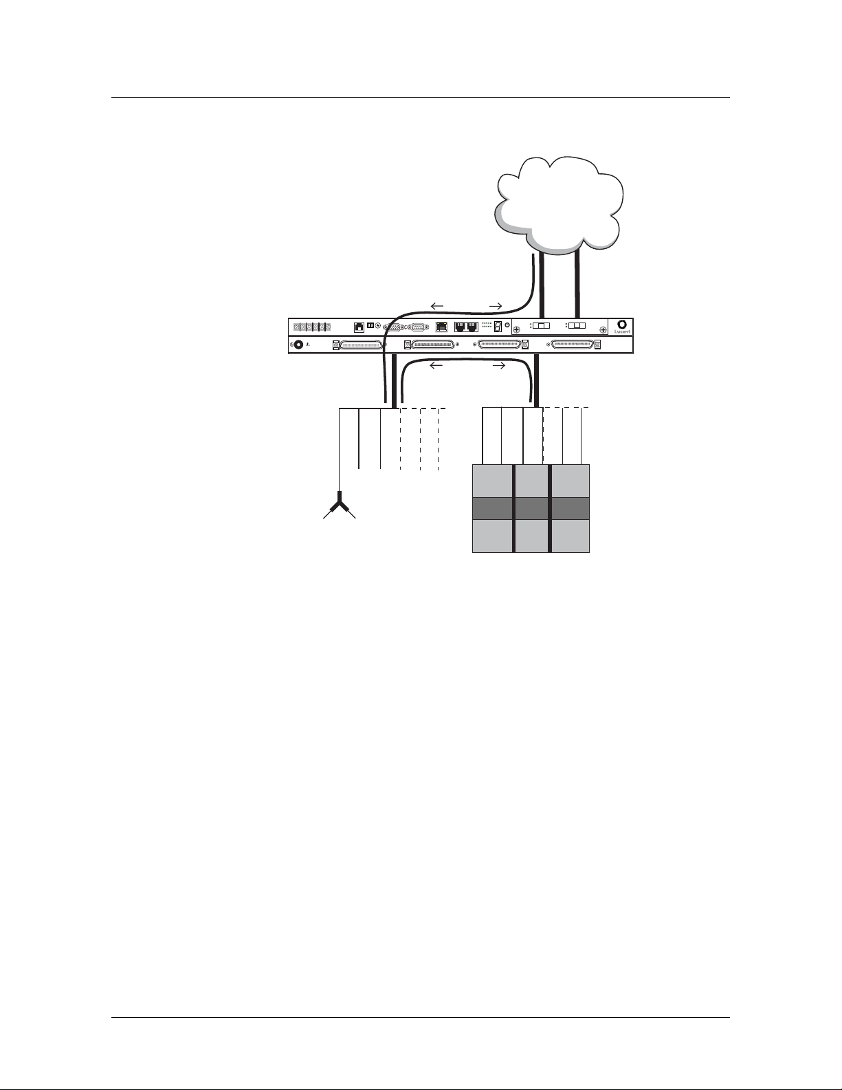
Stinger MRT Operational Overview
Stinger MRT operation as a DSL access multiplexer
Figure 5-1. Example of DSLAM operations with splitters for POTS service
POTS
SEE INSTRUCTION MANUAL
SIEHE ANLEITUNG
LIRE LE MANUEL d'INSTRUCTION
USE OF RING LUGS RECOMMENDED
-48VB
RTN B
MODEM
LINE 1-24
-48VA
RTN A
ATM network
(PVCs)
ATM data
SHELF
ALARM RELAY
IDBITS
ETHERNET 10BT
CONSOLE
MINOR
MAJOR
LINE 25-48
1
5
610
PORTS
ID
SELECT
SD
SD
LOS
LOS
POTS 25-48
PORT 2
PORT 1
POTS 1-24
GROUPSTATUS
EXP1
EXP2
POTS voice
traffic
POTS
telephone
Operation without splitters
A Stinger MRT not equipped with integrated splitters operates as an ATM
switch-through digital subscriber line access multiplexer (DSLAM). It switches data
from multiple subscribers on dedicated ADSL or SHDSL lines onto a high-speed ATM
backbone.
Figure 5-1 shows this type of operation.
Splitter
DSL
CPE
Telecommunications service provider
POTS switch
5-2 Stinger® MRT Getting Started Guide
Page 71

Figure 5-2. Example of pure DSLAM operation
DSL
CPE
Stinger MRT Operational Overview
Stinger MRT ATM switching overview
DSL traffic
241
RTN
RTN
48V B
48V A
B
A
LOS
SD
PORT 2
LOS
SD
PORT 1
PORTS PORTS
PORT
106
5
1
STATUS
EXP1
GROUP
SEL
EXP2
ATM n e twor k
(PVCs)
Stinger MRT ATM switching overview
A Stinger MRT unit receives cells on a link that is identified by a pair of unique
attributes. These attributes are known as the virtual path identifier (VPI) and the
virtual channel identifier (VCI). The Stinger MRT switches cells from an incoming
link to an outgoing link, based on the VPI and VCI attributes of each link. The
connection between these links is a static configuration entered by an administrator.
48 25
10BT
CONSOLE
MAJOR
SHELF
MRT
COOLING
SYSTEM STATUS
ID BITS
MINOR
ALARM
This guide covers only basic installation information and configuration of the Stinger
MRT unit. More detailed information about configuring the unit to support ATM
traffic can be found in the Stinger ATM Configuration Guide.
Stinger MRT configuration overview
Before you configure a Stinger MRT unit, create a diagram that illustrates how the
unit will interoperate with your current network configuration. Creating a
comprehensive network diagram helps prevent problems during installation and
configuration, and can help in troubleshooting any problems later.
Stinger MRT configuration tasks include the following:
■ Configuring the basic administrative parameters
Stinger® MRT Getting Started Guide 5-3
Page 72

Stinger MRT Operational Overview
Stinger MRT configuration overview
■ Configuring the DSL lines
■ Configuring the trunk module
■ Defining ATM traffic contracts
■ Configuring management connections, either locally or through RADIUS
■ Saving a backup copy of the system configuration
(For a summary of where to find additional specific configuration information, see
Table 5-1 on page 5-7.)
Administrative configuration
Each Stinger MRT has an RS-232 serial port (labeled CONSOLE) and a 10BaseT
Ethernet port that can be used to connect to the Stinger MRT to perform
administrative functions. Some Stinger units (model MRT-AD-36S-56K) also have an
internal analog modem that can be used for dial-in administrative connections.
The serial port is for system management from a local workstation. It is also the
standard port for error output, stack traces, and messages in the event of a system
crash. Until you have configured IP addresses on the system’s Ethernet interface, you
can use a local terminal or workstation connected to the serial port of the Stinger
MRT to configure the unit.
The system’s 10BaseT Ethernet port is intended for light administrative and
management traffic. Once you have assigned an IP address, you can telnet into the
unit from a local host and download configuration files from a TFTP server to the
Stinger system. A Stinger unit has a range of options for configuring IP and for
protecting the unit from unauthorized administrative access.
The internal modem is intended for administrative connections over an analog POTS
line. For modem connection and configuration details, see
configuring an internal modem” on page 6-12.
Line configuration
Stinger MRT units support ADSL, ASDL over POTS, and SHDSL service, depending
on the model purchased (see
port on a Stinger MRT has a variety of configuration options, including line rates and
bandwidth. The way you configure each line depends on the model you have
purchased, and your connectivity needs.
For specific information about line configuration, see Chapter 7, “Configuring the
ADSL Line Interfaces,” or Chapter 8, “Configuring the SHDSL line interfaces.”
Trunk module configuration
A Stinger MRT can be equipped with a trunk module that supports E1, T1,
OC3/STM1, or DS3 service. The trunk module can connect the Stinger to another
ATM switch. The line configuration includes settings that must match between the
local and far-end switch interfaces.
“Connecting to and
Chapter 1, “Introduction to the Stinger MRT”). Each
When a trunk module is installed in a Stinger MRT unit, use of the show command
gives the appearance of two trunk modules, as shown in the following example:
admin> show
Shelf 1 ( standalone ):
5-4 Stinger® MRT Getting Started Guide
Page 73

Stinger MRT Operational Overview
Stinger MRT management features
Reqd Oper Slot Type
{ shelf-1 slot-1 0 } UP UP mrt-36-adsl-card
{ shelf-1 trunk-module-1 0 } UP UP oc3-atm-trunk-daughter-card
{ shelf-1 trunk-module-2 0 } UP UP oc3-atm-trunk-daughter-card
The information displayed for trunk-module-1 is related to the self-contained STS-3
interfaces on the Stinger MRT chassis. Although these interfaces are permanently
installed on the chassis, to maintain the consistency of the command-line interface
with other Stinger models TAOS identifies them as being installed in slot 17.
Although the physical connection for the STS-3 interfaces uses CAT 5, UTP cable, the
configuration of the STS-3 connection is identical to the configuration of an OC3 line.
For specific information about STS-3 configuration, see
OC3-ATM Trunk Module.”
The information displayed for trunk-module-2 is related to the trunk module that is
installed in the single trunk module slot (see
the consistency of the command line interface with other Stinger models, this
module is identified by TAOS as being installed in slot 18.
For specific information about trunk module configuration, see the chapter for the
desired trunk module.
Figure 2-5 on page 2-7). To maintain
Chapter 10, “Configuring an
System clocking modes
The Stinger MRT requires a clock source for its timing subsystem. By default, it uses a
built-in 8kHz clock as its timing source. You can configure the system to take its clock
source from a trunk port or from an external building integrated timing supply
(BITS) clock connected to the BITS connector of the Stinger MRT.
For detailed configuration information see “Configuring system clocking (optional)”
on page 6-19.
Stinger MRT management features
To enable you to configure the system and monitor its activity, Stinger MRT units
support profiles, commands, and status windows in the command-line interface.
Stinger MRT units also support SNMP management, RADIUS profiles, and the ability
to upload (back up) and download software and configuration files via TFTP or serial
connections.
A Stinger MRT system provides several permission levels to control the management
and configuration functions that are accessible in the command-line interface. For
information about User profiles and other management features, see the Stinger
Administration Guide.
Using the command-line interface
The Stinger command-line interface provides access to commands, profiles, and
status windows. You must use the command-line interface to provide the initial
system and IP configuration for the unit, although you can choose to perform
subsequent configuration tasks remotely through a Telnet session or SNMP, or by
downloading configuration files via TFTP.
Stinger® MRT Getting Started Guide 5-5
Page 74

Stinger MRT Operational Overview
Stinger MRT management features
For an introduction to the command-line interface and its shortcuts, see the TAOS
Command-Line Interface Guide.
Onboard flash memory and software updates
You can perform software upgrades of the onboard flash memory in the field. You
upgrade the Stinger MRT unit by accessing it locally through its serial (CONSOLE)
port and downloading software upgrades from a TFTP server. For details, see the
Stinger Administration Guide.
SNMP support
In addition to managing a Stinger MRT unit by means of the command-line interface,
you can manage the unit by using an SNMP management station such as the
NavisAccess™ product. A Stinger MRT unit can generate SNMP traps (event
notifications) to indicate alarm conditions, and it relies on SNMP community strings
to implement SNMP security.
For information about using SNMP with Stinger MRT units, see the Stinger
Administration Guide, the Stinger SNMP Management of the ATM Stack Supplement, and
the documentation for Navis™ network management software.
RADIUS support
You can use RADIUS to store user profiles for ATM circuits and terminating
connections. The RADIUS server must be compliant with vendor-specific attributes
(VSAs), as defined in RFC
MRT unit to communicate with the RADIUS server.
For information about configuring and using RADIUS, see the TAOS RADIUS Guide
and Reference.
Tracking system activity
A Stinger MRT unit supports many commands for monitoring system activity. To
display the commands that are available with the permission settings in the current
User profile, enter the help (or ?) command. The following example shows the
commands available for the admin login. The left column shows command names,
and the right column shows the command class, which determines the permissions
required to use the command.
admin> ?
? ( user )
arptable ( system )
auth ( user )
callroute ( diagnostic )
clear ( user )
clock-source ( diagnostic )
clr-history ( system )
connection ( system )
date ( update )
debug ( diagnostic )
delete ( update )
device ( diagnostic )
dir ( system )
2138. To use RADIUS, you must also configure the Stinger
5-6 Stinger® MRT Getting Started Guide
Page 75

Stinger MRT Operational Overview
What’s next
dircode ( system )
ether-display ( diagnostic )
fatal-history ( system )
format ( code )
fsck ( code )
get ( system )
hdlc ( system )
[More? <ret>=next entry, <sp>=next page, <^C>=abort]
For details about each command, see the Stinger Reference. For more information
about command help, see the TAOS Command-Line Interface Guide.
The command-line interface supports several status windows that focus on different
aspects of system activity (such as connection status and log messages). The windows
provide a great deal of read-only information about what is currently happening in
the unit. To display a status window, enter the Status command:
admin> status
The system prompt moves to just below the status window. To close the status
window, enter the command again:
admin> status
If the system prompt is not visible below the status window, press Escape to display it.
Note Stinger MRT configuration settings are stored in onboard flash memory, and
must be backed up to a TFTP host whenever changes are made. For details about
backing up and restoring the Stinger MRT configuration, see the Stinger Administration
Guide.
What’s next
When you have planned your network, you are ready to configure the Stinger MRT
unit. You can perform configuration tasks in any order you want.
where to look for the information you need.
Table 5-1. Location of configuration information
Configuration task Location
Establish a serial connection “Making the initial administrative connection” on
Set up basic access security “Restricting administrative access” on page 6-3
Configure IP “Providing a basic system IP configuration” on
Configure the unit to use
RADIUS
Table 5-1 shows
page 6-2
page 6-6
TAOS RADIUS Guide and Reference
Configure the unit’s lines Chapter 7, “Configuring the ADSL Line
Interfaces.”
Chapter 8, “Configuring the SHDSL line
interfaces.”
Stinger® MRT Getting Started Guide 5-7
Page 76

Stinger MRT Operational Overview
What’s next
Table 5-1. Location of configuration information (continued)
Configuration task Location
Checking line port status Chapter 7, “Configuring the ADSL Line
Interfaces.”
Chapter 8, “Configuring the SHDSL line
interfaces.”
Configure the unit’s trunk
lines
Chapter 9, “Configuring T1 and E1 Trunk
Modules.”
Chapter 10, “Configuring an OC3-ATM Trunk
Module.”
Chapter 11, “Configuring a DS3-ATM Trunk
Module.”
Checking trunk status Chapter 9, “Configuring T1 and E1 Trunk
Modules.”
Chapter 10, “Configuring an OC3-ATM Trunk
Module.”
Chapter 11, “Configuring a DS3-ATM Trunk
Module.”
Define ATM traffic contracts Stinger ATM Configuration Guide
Configure ATM circuits Stinger ATM Configuration Guide
Configure virtual path
Stinger ATM Configuration Guide
switching
Check details about
Stinger Reference
parameters and commands
Use SNMP with the unit Stinger Administration Guide and the Stinger SNMP
Management of the ATM Stack Supplement
Configure login permissions Stinger Administration Guide
Back up the system
Stinger Administration Guide
configuration
Test lines and ports Stinger Administration Guide
5-8 Stinger® MRT Getting Started Guide
Page 77

Configuring Administrative Access, System Timing, and Startup Settings
6
Administrative configuration overview . . . . . . . . . . . . . . . . . . . . . . . . . . . . . . . . 6-1
Making the initial administrative connection . . . . . . . . . . . . . . . . . . . . . . . . . . . 6-2
Logging into the Stinger MRT . . . . . . . . . . . . . . . . . . . . . . . . . . . . . . . . . . . . . . . 6-3
Restricting administrative access . . . . . . . . . . . . . . . . . . . . . . . . . . . . . . . . . . . . . 6-3
Providing a basic system IP configuration . . . . . . . . . . . . . . . . . . . . . . . . . . . . . . 6-6
Additional administrative connections and configuration . . . . . . . . . . . . . . . . . . 6-9
Configuring system clocking (optional) . . . . . . . . . . . . . . . . . . . . . . . . . . . . . . . 6-19
Retaining basic configuration settings for remote administration . . . . . . . . . . . 6-22
Saving and loading a backup configuration . . . . . . . . . . . . . . . . . . . . . . . . . . . . 6-246-24
This chapter describes the tasks necessary for basic configuration of the Stinger MRT
unit as a stand-alone unit. Multiple Stinger MRT and MRT-2 units can also connected
together as a hosted system. Details of configuration for hosted operation are
described in
However, you must be familiar with the basic information described here, before
attempting to configure a hosted system.
Appendix B, “Hosted Operation of Cascaded Stinger MRT units.”
Administrative configuration overview
6-1
6-2
6-3
6-3
6-6
6-9
6-19
6-22
Administrative configuration includes the following tasks:
■ Connecting a console workstation to the CONSOLE serial port on the Stinger
MRT unit
■ Logging into the Stinger unit
■ Changing default security settings to protect the unit
■ Configuring IP to make the system accessible over its administrative network by
Telnet, SNMP, and Ping
■ Connecting and configuring additional types of administrative access
■ Configuring RADIUS access (if appropriate) (See the TAOS RADIUS Guide and
Reference.)
■ Configuring system clocking (if appropriate)
Stinger® MRT Getting Started Guide 6-1
Page 78

Configuring Administrative Access, System Timing, and Startup Settings
Making the initial administrative connection
■ Storing enough configuration information to restart the unit after clearing
nonvolatile RAM (NVRAM)
Note All connections that are illustrated in this section depict the Stinger MRT 23.
Connections for the Stinger MRT 19 are identical, except for the location of the
connectors on the front of the chassis. Connector locations for both models are
shown Chapter 2, in
Figure 2-3 and Figure 2-4.
Making the initial administrative connection
The serial port of a Stinger MRT is used for initial configuration from a console
device, or to reconfigure the unit from a console after NVRAM has been cleared.
After configuring the unit initially, you can connect as follows for dial-in
administrative access:
■ Connect an external modem to the serial port. (See “Connecting to and
configuring an external modem” on page 6-11.)
■ On a model MRT-AD-36S-56K unit, connect the internal modem to an analog
POTS line. (See
page 6-12.)
“Connecting to and configuring an internal modem” on
For other types of administrative connections, see “Additional administrative
connections and configuration” on page 6-9.
Figure 6-1 shows a cable connection from the Stinger MRT to a console terminal.
Figure 6-1. Serial management connection to the Stinger MRT
STATUS
EXP2
CONSOLE
R
MINO
RELAY
R
AJO
M
SD
INE 25-48
LOS
PORT 2
SD
ID
GROUP
LOS
STATUS
5
EXP2
EXP1
ETHERNET 10BT
CONSOLE
MINOR
ALARM RELAY
SHELF
8
7
9
6
0
5
1
POTS
4
2
3
R
-48VB
-48VA
R
MO
B
N
T
R
A
N
T
LINE 1-24
L
A
U
N
A
M
N
O
I
T
C
U
R
T
S
IN
N
G
O
E
I
N
E
T
U
S
C
IT
U
E
R
L
T
N
S
A
IN
'
E
d
H
L
D
IE
E
E
S
U
D
N
N
A
E
M
M
E
M
L
O
E
C
R
E
I
L
R
S
G
U
L
G
N
I
R
F
O
E
S
U
MAJO
ID
BITS
LINE 25-48
DEM
PORT 1
1
0
1
SELECT
6
PORTS
POTS 25-48
ETHERNET 10BT
POTS 1-24
EXP1
5
1
10
6
PORTS
SELECT
CONSOLE port
L
To console
serial port
To connect the console terminal to the Stinger MRT, connect one end of a shielded
straight-through cable to the CONSOLE port on the chassis. Then connect the other
end of the shielded straight-through cable to the serial port on the console device.
P
The CONSOLE port on the Stinger MRT consists of a female DB-9 connector.
Examine the serial connector of your PC or dumb terminal to ensure that your
shielded straight-through cable has the proper connectors. If needed, you can use
DB-9-to-DB-25 converters or gender converters to complete this connection.
For detailed information about the pinouts on the CONSOLE serial port, see
“CONSOLE port and cable pinouts” on page C-1.
6-2 Stinger® MRT Getting Started Guide
Page 79

Configuring Administrative Access, System Timing, and Startup Settings
Logging into the Stinger MRT
To configure the unit initially, or after using the nvram command to clear its
NVRAM, you must connect a workstation to the Stinger MRT CONSOLE port
After connecting the management workstation, launch a communications program
that supports terminal emulation. Make sure that the terminal emulation settings
specify 9600bps, 8
The default settings for the serial port profile allow anyone connecting to the
CONSOLE port to access the system as the administrative (admin) user, without
logging in or being authenticated. When you connect to an unconfigured Stinger
MRT to which power has been applied, you are presented with the prompt for the
admin user:
admin>
After you have supplied basic IP information, as described in “Providing a basic
system IP configuration” on page 6-6, you can access the Stinger command-line
interface by using Telnet from an IP host. Or, you can log in by using an SNMP
management station, such as NavisAccess™, from an IP host. These types of
connections require that you authenticate a User profile and supply a password to
acquire administrative permissions.
data bits, 1 stop bit, and no parity or flow control.
Logging into the Stinger MRT
During basic configuration, Lucent Technologies recommends that you also configure
the serial port to require username and password authentication. For details, see
“Restricting administrative access.”
For details about User profiles, see the Stinger Administration Guide.
Restricting administrative access
Each Stinger unit is shipped from the factory with its security features set to defaults
that allow you to easily access the unit so you can configure it without any
restrictions. Before you bring the unit online, you must change the default security
settings to protect the configured unit from unauthorized access.
Changing defaults for serial-port logins
The factory default setting for the serial interface specifies that any connection to that
interface will use the admin User profile. To help protect the system from
unauthorized administrative access on the serial interface, change the following
default setting:
[in SERIAL/{ shelf-1 control-module 2 }]
user-profile = admin
Parameter Setting
User-Profile
Stinger® MRT Getting Started Guide 6-3
Name of the User profile to be used for logins on the
Stinger MRT serial port. User profiles set permissions and
other parameters for logins to the Stinger command-line
interface. If no name is specified, the system prompts for
both the name and password of a User profile, as it does for
Telnet logins.
Page 80

Configuring Administrative Access, System Timing, and Startup Settings
Restricting administrative access
A Stinger MRT unit automatically creates a Serial profile for administrative access. To
list the Serial profiles, use the dir command as follows:
admin> dir serial
12 10/20/2000 02:57:48 { shelf-1 first-control-module 2 }
Note The designation first-control-module refers to the control module in slot 8
on larger models of the Stinger. Although control module functions are integrated
into the chassis of the Stinger MRT, TAOS uses a virtual location of slot 8 to access
profiles and settings associated with these functions. This behavior is reflected in the
configuration example that follows.
To make serial logins more secure, modify the Serial profile of the Stinger MRT to
specify a null User profile name, as shown in the following example. Anyone trying
to establish a connection through the serial port is then required to provide a
username and password.
admin> read serial {1 8 2}
SERIAL/{ shelf-1 first-control-module 2 } read
admin> set user-profile =
admin> write
SERIAL/{ shelf-1 first-control-module 2 } written
Changing the default admin password
Because the admin user profile controls permissions that enable most levels of
activity, access to that login must be carefully restricted. To protect the admin login,
change its well-known default password the first time you log into the unit.
Following is the password parameter, shown with its factory default setting:
[in USER/admin]
password = "Ascend"
Parameter Setting
Password
You can specify any password up to 20 characters. All future logins governed by the
admin User profile must provide the new password.
For example, the following commands change the admin password to x1!35DPG:
admin> read user admin
USER/admin read
admin> set password = x1!35DPG
admin> write
USER/admin written
Text string of up to 20 characters, which must be entered
by a user to log in with permissions authorized by the admin
profile. The value is case sensitive.
When an administrator telnets into the Stinger unit, the system prompts for the
name and password of a User profile and authenticates the information before
allowing the Telnet session. For example:
% telnet 1.1.1.1
Trying 1.1.1.1...
6-4 Stinger® MRT Getting Started Guide
Page 81

Configuring Administrative Access, System Timing, and Startup Settings
Connected to 1.1.1.1
Escape character is ‘^]’.
User: admin
Password: x1!35DPG
Setting a Telnet password
A Telnet password is a global, systemwide password required for Telnet logins to the
unit. The Telnet password is required before the system accepts the connection and
prompts for the username. Following are the default parameters associated with
Telnet logins to a Stinger unit:
[in IP-GLOBAL]
telnet-password = ""
user-profile = ""
Parameter Setting
Restricting administrative access
Telnet-Password
User-Profile
For example, the following commands set the Telnet password to dpg01!:
admin> read ip-global
IP-GLOBAL read
admin> set telnet-password = dpg01!
admin> write
IP-GLOBAL written
When a Telnet password has been specified, the system requires a two-tier password
authentication for Telnet logins, first the Telnet password, then the username and its
associated password. For example:
% telnet 1.1.1.1
<stinger01> Enter Password: dpg01!
Text string of up to 20 characters, required from all users
requesting a Telnet session. A user is allowed three
attempts, with 60 seconds per attempt, to enter the correct
password. A third unsuccessful attempt terminates the
login process. The value is case sensitive.
Name of a default User profile for authenticating all Telnet
logins. If no name is specified, the system prompts the user
to enter the name of a User profile.
Trying 1.1.1.1...
Connected to 1.1.1.1
Escape character is ‘^]’.
User: admin
Password: **********
If the user enters an incorrect Telnet password, the system prompts again, allowing
up to three attempts before timing out. If the user specifies the correct password, the
connection is established and the user is prompted to enter the name and password
of a valid User profile.
Stinger® MRT Getting Started Guide 6-5
Page 82

Configuring Administrative Access, System Timing, and Startup Settings
Providing a basic system IP configuration
Providing a basic system IP configuration
To enable Telnet and SNMP access to the unit, and to allow connectivity between the
unit and local IP hosts, you must assign IP addresses to the Stinger MRT Ethernet port
and configure basic IP routing.
Note A Stinger MRT unit does not require IP routing to operate as a DSLAM. IP
routing is not used by the DSLAM activities. The system does not provide IP routing
for DSLAM user data.
IP address syntax
The Stinger MRT unit uses dotted decimal notation (not hexadecimal) for IP
addresses. Netmask information is appended to the IP address after a forward slash
(/).
Netmasks
If no netmask is specified, the unit uses a default mask based on the class of the IP
address that is supplied.
bits in the default mask for each class.
Table 6-1 shows address classes and the number of network
Table 6-1. IP address classes and number of network bits
Class Address range Default network
bits
Class A 0.0.0.0 through 127.255.255.255 8
Class B 128.0.0.0 through
191.255.255.255
Class C 192.0.0.0 through
223.255.255.255
For example, a class C address, such as 198.5.248.40, has 24 network bits, leaving 8
bits for the host portion of the address. If no subnet mask is specified for a class C
address, the Stinger uses the default mask of 24 bits, as shown in
Figure 6-2. Default netmask for class C IP address
1 1 1 1 1 1 1 1 1 1 1 1 1 1 1 1 1 1 1 1 1 1 1 1 0 0 0 0 0 0 0 0
Default 24 bits
By default, this address is displayed as 198.5.248.40/24
16
24
Figure 6-2.
Subnets
Subnets are permitted under the same syntax. A subnet address specifies a number of
network bits that does not adhere to the Class A, B, or C network limits. For example,
the following address specifies a 29-bit subnet:
ip-address = 198.5.248.40/29
6-6 Stinger® MRT Getting Started Guide
Page 83

Configuring Administrative Access, System Timing, and Startup Settings
Providing a basic system IP configuration
In this address, 29 bits of the address are used to specify the network. The three
remaining bits are used to specify eight addresses on the subnet. With three bits used
to specify hosts on a 29-bit subnet, eight different bit combinations are possible. Of
those eight possible host addresses, two are reserved:
000 — Reserved for the network (base address)
001
010
100
110
101
011
111 — Reserved for the broadcast address of the subnet
Note Early implementations of TCP/IP did not allow zero subnets (subnets with the
same base address as a class A, B, or C network). For example, the subnet
192.32.8.0/30 was illegal because it had the same base address as the class C network
192.32.8.0/24, while the subnet 192.32.8.4/30 was legal. Modern implementations
of TCP/IP support zero subnets, and the Stinger MRT implementation of RIP treats
these subnets the same as any other network. Make sure that you treat zero subnets
consistently throughout your network. Otherwise, you can encounter routing
problems.
Table 6-2 shows subnet masks and prefix lengths for a class C network.
Table 6-2. Decimal subnet masks and prefix lengths
Subnet mask Number of host addresses Prefix
length
255.255.255.0 254 hosts + 1 broadcast address, 1 network base
/24
address
255.255.255.128 126 hosts + 1 broadcast address, 1 network base
/25
address
255.255.255.192 62 hosts + 1 broadcast address, 1 network base
/26
address
255.255.255.224 30 hosts + 1 broadcast address, 1 network base
/27
address
255.255.255.240 14 hosts + 1 broadcast address, 1 network base
/28
address
255.255.255.248 6 hosts + 1 broadcast address, 1 network base
/29
address
255.255.255.252 2 hosts + 1 broadcast address, 1 network base
/30
address
255.255.255.254 Invalid mask (no hosts) /31
255.255.255.255 1 host—a host route /32
Stinger® MRT Getting Started Guide 6-7
Page 84

Configuring Administrative Access, System Timing, and Startup Settings
Providing a basic system IP configuration
The broadcast address of any subnet has the host portion of the IP address set to all 1s
(ones). The network address (or base address) represents the network itself, because
the host portion of the IP address is all 0s (zeros). For example, supposing that the
Stinger MRT configuration assigns the following address to a remote router:
198.5.248.120/29
The Ethernet network attached to that router has the following address range:
198.5.248.120 — 198.5.248.127
A host route is a special-case IP address with a prefix length of /32. For example:
198.5.248.40/32
Host routes are routes to a single host, rather than to a network or subnet. This is
determined by the fact that a 32-bit netmask does not allow for any host addresses on
the network, other than the single address that is specified. It is, in effect, a
one-address subnet.
Assigning the Ethernet IP addresses
A Stinger MRT unit creates an IP interface for the Ethernet port on the chassis. Use
the dir command to list the IP interface, as follows:
admin> dir ip-interface
18 11/03/2000 16:36:32 { { any-shelf any-slot 0 } 0 }
29 11/03/2000 16:27:57 { { shelf-1 first-control-module 1 } 0 }
Note The designation first-control-module refers to the control module in slot
8 on larger models of the Stinger. Although control module functions are integrated
into the chassis of the Stinger MRT, TAOS uses a virtual location of slot 8 to access
profiles and settings associated with these functions. This behavior is reflected in the
configuration example that follows.
The following commands assign the address 1.1.1.1/24:
admin> read ip-interface { { shelf-1 8 1 } 0 }
IP-INTERFACE/{ { shelf-1 first-control-module 1 } 0 } read
admin> set ip-address = 1.1.1.1/24
admin> write
IP-INTERFACE/{ { shelf-1 first-control-module 1 } 0 } written
After you assign IP addresses, you can verify that the Stinger MRT unit is a valid IP
host on its configured network by pinging other network hosts, as shown in the
following example:
admin> ping 1.1.1.56
PING 1.1.1.56: 56 Data bytes
64 bytes from 1.1.1.56: icmp_seq=0 ttl=255 time=0 ms
64 bytes from 1.1.1.56: icmp_seq=3 ttl=255 time=0 ms
^C
--- 1.1.1.56: Ping statistics --2 packets transmitted, 2 packets received, 0% packet loss
round-trip min/avg/max = 0/0/0 ms
6-8 Stinger® MRT Getting Started Guide
Page 85

Configuring Administrative Access, System Timing, and Startup Settings
Configuring a default route
A default route is a static route that specifies a destination for addresses that are not
on the local network and to which a known route does not exist. The default route is
generally the IP address of an external router that has more route information about
how specific destinations can be reached. When the default route is configured, the
Stinger MRT unit routes all IP packets with unknown destinations to the specified
external router. If no default route is defined, the unit drops IP packets for which it
has no route.
Figure 6-3 shows the Stinger MRT Ethernet interfaces on a subnet, connected to the
same Ethernet segment as a local backbone router. In this network, the Stinger MRT
can use the local router as its default route.
Figure 6-3. Local backbone router to be used as default route
Local
Additional administrative connections and configuration
Stinger MRT chassis
Ethernet port
1.1.1.3/241.1.2.3/24
Hub
1.1.1.1/24
Assuming a local router as the unit’s default route, or gateway, enables the Stinger
MRT unit to pass all IP packets with an unrecognized address to that router, so its
own routing tables can remain small. The external router maintains larger routing
tables, and assumes the responsibility and overhead of routing most packets.
For example, the following commands define a default route to the LAN router in
Figure 6-3:
admin> new ip-route default
IP-ROUTE/default read
admin> set gateway-address = 1.1.1.3
admin> set active-route = yes
admin> write
IP-ROUTE/default written
The system can support multiple default routes. The profile name does not have to be
default. The only requirements are that the destination address must be zero, and
Gateway-Address must specify a valid, accessible router.
For information about other settings in the IP-Route profile, see the Stinger Reference.
Additional administrative connections and configuration
Administration of the Stinger MRT can be managed from a remote workstation over
several different types of connections.
■ An Ethernet LAN
■ An analog modem (internal or external)
Stinger® MRT Getting Started Guide 6-9
Page 86

Configuring Administrative Access, System Timing, and Startup Settings
Additional administrative connections and configuration
■ A terminating permanent virtual circuit (PVC)
The following information provides background to help you set up and configure the
Stinger MRT for these administrative connections.
Connecting to an Ethernet LAN
After the IP address of the Stinger MRT has been configured, and the unit has been
connected to a network, an administrative Telnet connection can be established
through the network. (To configure an IP address, see
addresses” on page 6-8.)
Figure 6-4 shows an Ethernet network connection from the Stinger unit to the
management workstation.
Figure 6-4. Ethernet connection
CONSOLE
MINOR
RELAY
MAJOR
INE 25-48
D
S
S
O
L
2
T
R
O
P
D
S
ID
P
U
O
R
G
S
U
S
T
A
O
T
L
S
2
P
X
E
1
1
P
X
E
T
6
B
0
1
T
E
N
R
E
H
T
E
E
L
O
S
N
O
C
R
O
IN
M
Y
A
L
E
R
M
R
A
L
A
F
L
E
H
S
8
7
9
6
0
S
5
1
T
O
P
4
2
3
R
O
J
B
V
8
-4
A
8V
-4
B
N
T
R
4
-2
1
A
N
E
T
IN
R
L
L
SEE INSTRUCTION MANUA
TRUCTION
SIEHE ANLEITUNG
LIRE LE MANUEL d'INS
S RECOMMENDED
USE OF RING LUG
A
M
ID
S
IT
B
8
-4
5
2
E
IN
L
M
E
D
O
M
P
1
T
R
O
5
P
0
1
T
C
E
L
E
S
S
8
T
-4
R
5
O
2
S
T
O
P
Ethernet port
ETHERNET 10BT
4
-2
1
S
T
O
P
“Assigning the Ethernet IP
STATUS
EXP1
EXP2
5
1
10
6
PORTS
SELECT
Workstation
Ethernet port
L
P
To connect a management workstation to the Stinger using an indirect Ethernet
connection:
1 Connect one end of the Ethernet cable to the Ethernet RJ-45 port on the Stinger
MRT.
2 Connect the other end of the Ethernet cable to the local LAN.
3 Ensure that the management workstation has connectivity to the LAN on which
the unit resides. (See
“Verifying a LAN connection for administrators” on
page 6-10.)
4 Ensure the Ethernet transceivers are connected properly to the network.
Verifying a LAN connection for administrators
To enable administrators to log into the Stinger MRT unit’s interface from IP hosts,
you must also make sure your local network can route to the unit. Your network
router must have network connectivity through intermediate routers so that the
administrative host can access the Stinger MRT via its IP address. You can test this
connectivity by pinging the unit from the local host. For example, the following
command entered on a local host tests connectivity to a Stinger MRT with an IP
address of 1.1.1.128:
% ping 1.1.1.128
PING 1.1.1.128 (1.1.1.128): 56 Data bytes
Router
6-10 Stinger® MRT Getting Started Guide
Page 87

Configuring Administrative Access, System Timing, and Startup Settings
Additional administrative connections and configuration
64 bytes from 1.1.1.128: icmp_seq=0 ttl=255 time=0 ms
64 bytes from 1.1.1.128: icmp_seq=7 ttl=255 time=0 ms
^C
--- 1.1.1.128 Ping statistics --8 packets transmitted, 8 packets received, 0% packet loss
round-trip min/avg/max = 0/0/0 ms
Connecting to and configuring an external modem
To configure an administrative connection with an external modem, connect the
modem to the Stinger MRT serial (CONSOLE) port with a null modem (crossover)
cable. In addition, you might need a DB-25-to-DB-9 adapter.
administrative connection with a modem to the Stinger MRT unit.
Figure 6-5. Administrative connection with a modem to the Stinger MRT unit
Figure 6-5 shows the
L
RELAY
MINOR
CONSOLE
ETHERNET 10BT
STATUS
EXP2
EXP1
5
1
10
PORTS
SELECT
6
MAJOR
D
S
S
INE 25-48
O
L
2
T
R
O
P
D
S
ID
P
U
O
R
G
S
U
S
T
A
O
T
L
S
1
T
R
O
5
P
2
P
X
E
1
1
P
X
E
0
1
T
C
E
L
E
S
T
6
B
0
1
T
E
N
R
E
H
T
S
E
E
L
O
S
N
O
C
R
O
IN
M
Y
A
L
E
R
M
R
A
L
A
F
L
E
H
S
8
7
9
6
0
S
5
1
T
O
P
4
2
3
R
O
J
B
V
8
4
-
A
V
8
4
RTN B
4
-2
1
E
IN
RTN A
L
L
A
U
N
A
M
N
IO
T
C
U
R
T
S
N
N
I
G
O
E
I
N
E
T
U
S
C
IT
U
E
R
L
T
N
S
A
'IN
E
d
H
L
E
D
I
E
E
S
U
D
N
N
A
E
M
M
E
M
L
O
E
C
R
E
I
L
R
S
G
U
L
G
IN
R
F
O
E
S
U
A
M
ID
S
IT
B
8
-4
5
2
E
IN
L
M
E
D
O
M
8
T
4
-
R
5
O
2
P
S
T
O
P
CONSOLE port
4
-2
1
S
T
O
P
To modem
The modem you use to connect to the Stinger MRT unit must be configured as
follows:
■ Dumb mode. Dumb mode causes the modem to ignore data on the receive data
(RD) lead.
■ Ignore on-to-off transitions of the data-terminal ready (DTR) lead.
■ Autoanswer enabled.
■ 8 bits, 1 stop bit, and no parity.
Configure the following AT commands on the modem:
at&d0 Ignore DTR state.
P
ats0=1 Answer automatically after one ring.
ate0 No echo (required).
at&c0 Assert the data carrier detect (DCD) signal.
atq1 Result codes are not sent.
at&w0 Store in nonvolatile RAM (NVRAM) as profile 0 (zero).
at&y0 Use stored configuration from profile 0 (zero) on startup.
Stinger® MRT Getting Started Guide 6-11
Page 88

Configuring Administrative Access, System Timing, and Startup Settings
Additional administrative connections and configuration
Connecting to and configuring an internal modem
Some Stinger MRT units (model MRT-AD-36S-56K) are equipped with an internal
modem. This modem is configured by default to automatically answer any incoming
calls. For this reason, you need only connect the telephone line to the RJ-11 jack on
the face of the unit.
Figure 6-6. Connection for internal modem
Figure 6-6 shows a connection for an internal modem.
SHELF
7
6
POTS
-48VB
MODEM
RTN B
1
XP
E
T
B
0
1
T
E
N
R
E
H
T
E
E
L
O
24
S
N
O
C
R
O
IN
M
Y
A
L
E
R
M
R
A
L
A
F
L
E
H
S
8
7
9
6
0
S
5
1
T
O
P
4
2
3
R
JO
B
V
8
4
-
A
V
8
4
TN B
R
-24
1
E
TN A
IN
R
L
MANUAL
UNG
SEE INSTRUCTION
INSTRUCTION
ED
SIEHE ANLEIT
D
LIRE LE MANUEL d'
USE OF RING LUGS RECOMMEN
A
M
ID
S
IT
B
SEE INSTRUCTION MANUAL
8
-4
5
2
E
IN
L
M
E
D
O
M
SIEHE ANLEITUNG
LE MANUEL d'INSTRUCTION
UGS RECOMMENDED
P
U
O
R
G
S
U
T
A
T
S
5
2
P
EX
1
10
6
S
T
R
O
P
POTS
D
S
ID
S
O
L
T
C
E
L
E
S
S
T
O
P
connector
5
4
ID
BITS
D
S
S
O
L
2
T
R
O
P
T 1
R
O
P
8
-4
5
2
8
2
3
O
P
9
0
1
4
-2
1
S
T
ALARM RELAY
LINE 25-48
MINOR
MAJOR
CONSOLE
ETHERNET 10BT
POTS line
Configuring an internal modem
Use the Modem profile to set the autoanswer, country code, and inactivity time-out
configuration of the modem. Following is a sample of this profile with its default
settings:
[in MODEM/{ shelf-1 first-control-module 3 }]
physical-address* = { shelf-1 first-control-module 3 }
auto-answer = on
country-code = unitedstates
inactivity-time = 0
The auto-answer parameter has two valid settings:
Setting Specifies
on
off
primary-only
If the Stinger MRT unit is equipped with an internal domestic modem, the only valid
setting for the country-code parameter is unitedstates. If the unit is equipped with
an international modem, the country-code parameter can be set to support the
national regulations of several specific countries.
The internal modem automatically answers any incoming
call and attempts to negotiate modem protocols with the
caller.
The internal modem ignores incoming calls.
Not valid for the Stinger MRT.
You can use the cmmodemShowCountries command to check for the presence of an
international modem. When used on units equipped with an international modem,
this command will display a list of valid country code settings for the country-code
parameter. When used on units with a domestic modem, no response will be
6-12 Stinger® MRT Getting Started Guide
Page 89

Configuring Administrative Access, System Timing, and Startup Settings
Additional administrative connections and configuration
displayed. The default setting unitedstates is the only valid setting for the
country-code parameter on units with domestic modems.
The inactivity-time setting controls the number of seconds of inactivity that must
elapse before a connection to the internal modem is dropped. Valid entries are from 0
to 255 seconds. A setting of 0 disables this feature, and allows the connection to
remain active indefinitely.
Administrative terminating PVC connections
After the IP address of the Stinger MRT has been configured, and the trunk module of
the unit has been connected to an ATM switch, you can establish an administrative
Telnet connection through a PVC that has been configured to terminate as an IP
connection within the unit.
(To configure an IP address, see “Assigning the Ethernet IP addresses” on page 6-8. To
connect the trunk module to an ATM switch, see the applicable trunk module
chapter.)
To establish a Telnet connection to the Stinger MRT, you must use a workstation that
has IP access to the network that is at the far end of the ATM link.
Overview of a terminating ATM connection
A terminating ATM connection is a PVC that is not switched through the system and
forwarded out to the ATM network. Instead, this type of connection terminates in the
Stinger MRT system itself and is passed up to the IP router for further handling. As an
example of a terminating routed IP connection,
Telnet or SNMP login from a remote workstation (4.4.4.1/24) to the Stinger MRT
interface across an ATM trunk.
Figure 6-7 shows an administrative
Stinger® MRT Getting Started Guide 6-13
Page 90

Configuring Administrative Access, System Timing, and Startup Settings
Additional administrative connections and configuration
Figure 6-7. Terminating ATM connection
Terminating
connection
ATM
3.3.3.1/24
DSL Terminator
1.1.1.1/24
ALARM RELAY
ETHERNET 10BT
CONSOLE
MINOR
MAJOR
LINE 25-48
1
610
PORTS
PORT
5
SELECT
SD
SD
LOS
LOS
PORT 2
PORT 1
POTS 25-48
POTS 1-24
4.4.4.1/24
SEE INSTRUCTION MANUAL
SIEHE ANLEITUNG
LIRE LE MANUEL d'INSTRUCTION
USE OF RING LUGS RECOMMENDED
SHELF
POTS
-48VB
-48VA
RTN B
RTN A
IDBITS
MODEM
LINE 1-24
GROUPSTATUS
EXP1
EXP2
1.1.1.3/24
2.2.2.1/32
1.1.2.3/24
A terminating connection uses a single physical interface in a Stinger MRT unit, such
as the trunk interface shown in
Figure 6-7. It is an ATM connection that carries IP
packets, which are reassembled in the Stinger MRT unit and then handled as regular
IP traffic.
The profile for a terminating connection must specify the far-end IP address, and it
can set a number of other routing-related values. The profile must also specify the
ATM characteristics of the connection—for example, a virtual path identifier (VPI)
and virtual channel identifier (VCI) assignment, a nailed group, and the type of
protocol multiplexing to use for the ATM adaptation layer 5 (AAL5).
Overview of terminating PVC settings
A terminating PVC can be configured in a single connection or RADIUS profile. The
cells received on the connection are reassembled into IP packets. The connections are
not password authenticated.
For information about configuring a RADIUS profile, see the TAOS RADIUS Guide and
Reference.
Local Connection profile settings
Following are the connection parameters (shown with sample settings) for ATM
terminating connections:
[in CONNECTION/management]
station* = management
active = yes
encapsulation-protocol = atm
6-14 Stinger® MRT Getting Started Guide
Page 91

Configuring Administrative Access, System Timing, and Startup Settings
Additional administrative connections and configuration
[in CONNECTION/"":ip-options]
ip-routing-enabled = yes
remote-address = 3.3.3.3/24
[in CONNECTION/"":atm-options]
atm1483type = aal5-llc
vpi = 0
vci = 35
nailed-group = 1
cast-type = p2p
conn-kind = pvc
vp-switching = no
[in CONNECTION/"":atm-qos-options]
usr-up-stream-contract = ""
usr-dn-stream-contract = ""
Parameter Setting
station Name of the far-end device.
active Enable/disable the profile for active use.
encapsulation-protocol Encapsulation protocol to use for the connection. This
parameter must be set to atm for terminating
connections.
ip-options:
ip-routing-enabled
Enable/disable IP routing for the interface. IP routing
must be enabled (as it is by default) for terminating
connections.
ip-options:
remote-address
IP address of the far-end device, which can include a
subnet specification. If it does not include a subnet
mask, the router software in the Stinger MRT unit
assumes a default subnet mask that is based on address
class. (For related information, see
“Netmasks” on
page 6-6.)
atm-options:
atm1483type
Method of multiplexing Layer-3 packets into ATM cells.
Valid values are AAL5-LLC and AAL5-VC.
atm-options:vpi VPI for the connection. For a discussion of valid VPI
values, see the Stinger ATM Configuration Guide.
atm-options:vci VCI for the connection. For a discussion of valid VCI
values, see the Stinger ATM Configuration Guide.
atm-options:
nailed-group
Number of the dedicated (nailed) group for the physical
interface used by the connection. (Use the which
command to display a port’s nailed-group number. For
details, see the Stinger ATM Configuration Guide.)
atm-options:cast-type Connection topology type. Only the default
point-to-point (p2p) value is valid.
atm-options:conn-kind Kind of connection. Because the Private
Network-to-Network Interface (PNNI) protocol is not
supported on the Stinger MRT at this time, pvc (the
default) is the only valid setting.
Stinger® MRT Getting Started Guide 6-15
Page 92

Configuring Administrative Access, System Timing, and Startup Settings
Additional administrative connections and configuration
Parameter Setting
atm-options:
vp-switching
atm-qos-options:
usr-up-stream-contract
atm-qos-options:
usr-dn-stream-contract
Not used for terminating connections. (See the Stinger ATM
Configuration Guide.)
Name of atm-qos profile to be applied to upstream
traffic. See the Stinger ATM Configuration Guide.
Name of the atm-qos profile to be applied to
downstream traffic. See the Stinger ATM Configuration
Guide.
IP information
When a Stinger MRT unit starts up, it creates a routed interface for terminating
connections specified in local connection profiles. For those connections defined in
RADIUS profiles, a Stinger unit creates a routing interface when a session becomes
active.
The IP address of the far-end device is the minimum IP information that must be
supplied in the profile. The default settings for the
routing. They also enable Van Jacobson header compression and turn off RIP, which
is appropriate for many IP connections. You can change these defaults, or set a
variety of routing and service parameters (which are described in the Stinger
Reference). The far-end device specifies the Stinger MRT unit’s IP address as its
destination.
ip-options subprofile enable IP
Typical terminating PVC configuration for an administrative connection
A Stinger MRT unit establishes a PVC to a far-end unit on the basis of the VPI-VCI
assignment and other ATM parameters. For an IP-routed connection, the unit then
validates the far-end device’s IP address. After the connection has been established,
users can Telnet across the connection or access the Stinger MRT from an SNMP
management station.
In the example illustrated in Figure 6-8, a Stinger MRT unit has a connection or
RADIUS profile for the DSLTNT® unit, and vice versa. The ATM PVC between the
two units allows an administrator at the DSLTNT® side to connect to the Stinger unit,
where he or she can authenticate the appropriate user profile for an administrative
session.
6-16 Stinger® MRT Getting Started Guide
Page 93

Configuring Administrative Access, System Timing, and Startup Settings
t
Additional administrative connections and configuration
Figure 6-8. Management connection from a remote network
3.3.3.3/24
ATM
1.1.1.128/24
ALARM RELAY
ETHERNET 10BT
CONSOLE
MINOR
MAJOR
LINE 25-48
1
610
PORTS
PORT
5
SELECT
SD
SD
LOS
LOS
PORT 2
PORT 1
POTS 25-48
POTS 1-24
SEE INSTRUCTION MANUAL
SIEHE ANLEITUNG
LIRE LE MANUEL d'INSTRUCTION
USE OF RING LUGS RECOMMENDED
SHELF
POTS
-48VB
-48VA
RTN B
RTN A
IDBITS
MODEM
LINE 1-24
GROUPSTATUS
EXP1
EXP2
Managemen
workstation
Figure 6-8 shows the IP address of 1.1.1.128/24 assigned to the Stinger MRT.
Sample Stinger MRT configuration
In Figure 6-8, the connection from the Stinger MRT to the DSLTNT® unit uses an
OC3-ATM interface. The following commands create a local connection profile and
specify the IP address of the DSLTNT® unit:
admin> new connection dsltnt-1
CONNECTION/dsltnt-1 read
admin> set active = yes
admin> set encapsulation-protocol = atm
admin> set ip-options remote-address = 3.3.3.3/24
The following commands specify the AAL5 multiplexing method and assign VCI 101
to the link:
admin> set atm-options atm1483type = aal5-llc
admin> set atm-options vci = 101
The following commands display the nailed-group number of the OC3 trunk
interface (trunk
module 1, port 2) and assign it to the PVC:
admin> which -n {1 18 2}
Nailed group corresponding to port { shelf-1 trunk-module-1 1 } is 802
admin> set atm-options nailed-group = 852
The following commands assign an upstream and downstream quality of service
(QoS) contract and write the profile:
admin> set atm-qos-options usr-up-stream-contract = cbr
admin> set atm-qos-options usr-dn-stream-contract = cbr
admin write
CONNECTION/dsltnt-1 read
Stinger® MRT Getting Started Guide 6-17
Page 94

Configuring Administrative Access, System Timing, and Startup Settings
Additional administrative connections and configuration
Following is a comparable definition in a RADIUS profile:
permconn-ST-1 Password = "ascend"
Service-Type = Outbound,
Framed-Protocol = ATM-1483,
User-Name = "dsltnt-1",
Framed-IP-Address = 3.3.3.3,
Framed-IP-Netmask = 255.255.255.0,
Ascend-ATM-Group = 802,
Ascend-Route-IP = Route-IP-Yes,
Ascend-ATM-Vci = 101,
Ascend-QOS-Upstream = "cbr",
Ascend-QOS-Downstream = "cbr"
Sample far-end DSLTNT configuration
In this example, the DSLTNT® unit has a DS3 interface to the ATM network. The
following command displays the nailed-group value assigned to the DS3-ATM
interface used for this connection:
admin> get atm-ds3 {1 7 1} line-config nailed-group
[in ATM-DS3/{ shelf-1 slot-7 1 }:line-config]
nailed-group = 70
The following commands on the DSLTNT® unit configure a connection profile for the
Stinger MRT connection using the unit’s IP address and VCI 101:
admin> get connection stinger-1
CONNECTION/stinger-1 read
admin> set active = yes
admin> set encapsulation = atm
admin> set ip-options remote-address = 1.1.1.128/24
admin> set telco-options call-type = ft1
admin> set telco-options nailed-group = 70
admin> set atm-options vci = 101
admin> write
CONNECTION/stinger-1 written
For more details about creating connection profiles on DSLTNT® units, see the
DSLTNT® documentation.
Checking the status of a terminating PVC
For examples of commands you can use to check connection status of virtual links
and connections, see the Stinger ATM Configuration Guide. The same commands apply
to terminating or cross-connected PVCs.
For terminating PVCs, the values in the atmvcc-stat and atmpvc-stat profiles are
slightly different for terminating connections. Following are the relevant parameters
(shown with sample settings):
[in ATMVCC-STAT/{ shelf-1 slot-17 1 0 35 }]
vcc-ident* = { shelf-1 slot-17 1 0 35 }
circuit-name = dsltnt-1
6-18 Stinger® MRT Getting Started Guide
Page 95

Configuring Administrative Access, System Timing, and Startup Settings
current-state = vcc-data-transfer
vcc-type = terminating
[in ATMPVC-STAT/dsltnt-1]
circuit-name* = dsltnt-1
pvc-type = terminating
current-state = pvc-data-transfer
vcc-members = [ { shelf-1 slot-17 1 0 35 }]
For terminating connections, the value of the vcc-type and pvc-type parameters is
always terminating, and vcc-members always specifies a single member. The rest of
the parameters in the profiles are the same for terminating PVCs as for ATM circuits.
For details, see the Stinger ATM Configuration Guide.
Configuring system clocking (optional)
The Stinger MRT requires a clock source for its timing subsystem. By default, it uses a
built-in 8kHz clock as its timing source. You can configure the system to take its clock
source from a trunk port or from an external building integrated timing supply
(BITS) clock connected to the Stinger BITS connector.
Following is the relevant TAOS parameter, shown with its default value:
[in SYSTEM]
system-8k-clock = controller
Configuring system clocking (optional)
Parameter Setting
System-8K-Clock Source for the master system clock.
Using the BITS clock source
The following commands cause the system to first attempt to use a BITS clock as its
clock source, and to use the built-in clock only if it does not find a valid BITS signal:
admin> read system
SYSTEM read
admin> set system-8k-clock = bits
admin> write
SYSTEM written
■ With the default controller setting, the Stinger MRT
unit uses the built-in 8kHz clock.
■ If set to lim-or-trunk-module, the unit obtains its clock
signal from a trunk port that has been configured as an
eligible clock source, using the ports in order of their
priority. If no eligible trunk ports are available, it uses
the internal clock.
■ If set to bits, the unit sources its clock from the BITS T1
framer on its BITS connector.
Loss of BITS signal indications and fall-back
If the system-8K-clock parameter in the system profile is set to bits and the system
detects a loss of signal, it displays the following message:
Stinger® MRT Getting Started Guide 6-19
Page 96

Configuring Administrative Access, System Timing, and Startup Settings
Configuring system clocking (optional)
LOG alert, Shelf 1, Controller-1, Time: 17:02:01--
BITS clock source has been lost - 8kHz clock is free running
If no other clock source is eligible, the system then displays the following message:
LOG notice, Shelf 1, Controller-1, Time: 17:02:01
Master clock source changed to local oscillator
When the Stinger unit recovers the BITS signal, it displays the following messages:
LOG alert, Shelf 1, Controller-1, Time: 17:02:03--
BITS clock source has been recovered - 8kHz clock is locked
LOG notice, Shelf 1, Controller-1, Time: 17:02:03--
Master clock source changed to T1 framer
If the Stinger MRT unit detects a T1 signal in the BITS input, it prioritizes the clock
source list as follows:
■ If the system-8K-clock parameter of the system profile is set to bits, its priority is
set to the highest (1) and the T1 framer is selected regardless of other available
clock sources and priorities.
■ If the system-8K-clock parameter of the system profile is set to a value other than
bits, its priority is set as the lowest (3) and the T1 framer is selected as a clock
source only if no other slot clock sources are available.
Changing the BITS clock source
The following examples show how to change system-8K-clock parameter setting
from bits to lim-or-trunk-module and use the slot-clock-source command to view
the changes in clock source priority.
admin> set system-8k-clock = bits
admin> write
LOG notice, Shelf 1, Controller-1, Time: 17:55:34--
Master clock source changed to T1 framer
SYSTEM written
admin> slot-clock-source
Master line: T1 framer
Source List:
Source: line 1 Available* priority: 2
Source: line 2 Available* priority: 1
Source: T1 framer Available* priority: 1
admin> set system-8k-clock = lim-or-trunk-module
admin> write
LOG notice, Shelf 1, Controller-1, Time: 17:56:05--
Master clock source changed to slot-1/8 line 2
SYSTEM written
admin> slot-clock-source
Master line: 2
source List:
6-20 Stinger® MRT Getting Started Guide
Page 97

Configuring Administrative Access, System Timing, and Startup Settings
Source: line 1 Available* priority: 2
Source: line 2 Available* priority: 1
Source: T1 framer Available* priority: 3
Using a trunk module clock source
The following commands cause the system to first attempt to use a trunk port as its
clock source, and to use the built-in clock only if it finds no ports that are eligible
clock sources:
admin> read system
SYSTEM read
admin> set system-8k-clock = lim-or-trunk-module
admin> write
SYSTEM written
Configuring trunk ports as eligible clock sources
The DS3-ATM and OC3-ATM profiles support Clock-Source and Clock-Priority
parameters for specifying whether the port can be used to source the ATM network
clock and use it as the master clock for the unit. Each of the trunk ports can be
configured as eligible or ineligible for this use, and can be assigned a high, middle, or
low priority for being elected as the clock source. Following are the relevant
parameters, shown with default settings:
Configuring system clocking (optional)
[in DS3-ATM/{ any-shelf any-slot 0 }:line-config]
clock-source = not-eligible
clock-priority = middle-priority
[in OC3-ATM/{ any-shelf any-slot 0 }:line-config]
clock-source = not-eligible
clock-priority = middle-priority
Parameter Setting
clock-source Enable/disable obtaining the system clock signal from the
port. By default, ports are not eligible clock sources.
clock-priority
If more than one line is eligible to be the clock source, the system chooses the one
with the highest priority, as specified by the Clock-Priority setting. If multiple sources
of equal priority are present, the system selects the first valid clock source. (A clock
source is valid if the Clock-Source parameter is set to eligible and the DS3 or OC
interface is synchronized.)
Priority of the interface as the system’s clock source (high,
middle, or low priority). Once the Stinger MRT unit chooses
a clock source, it uses that source until the interface
becomes unavailable or a higher-priority source becomes
available.
Once it has selected a clock source, the system uses that source until the source
becomes unavailable or a higher-priority source becomes available. If no eligible
external sources exist, the system uses an internal clock.
Stinger® MRT Getting Started Guide 6-21
Page 98

Configuring Administrative Access, System Timing, and Startup Settings
Retaining basic configuration settings for remote administration
Typical trunk port clock source configurations
The following sample commands configure both ports of the a DS3-ATM module as
eligible clock sources, with the first port assigned a higher priority for this use:
admin> read ds3-atm { 1 trunk-module-2 1 }
DS3-ATM/{ shelf-1 trunk-module-1 1 } read
admin> set line-config clock-source = eligible
admin> set line-config clock-priority = high
admin> write
DS3-ATM/{ shelf-1 trunk-module-2 1 } written
admin> read ds3-atm { 1 trunk-module-2 2 }
DS3-ATM/{ shelf-1 trunk-module-1 2 } read
admin> set line-config clock-source = eligible
admin> set line-config clock-priority = low
admin> write
DS3-ATM/{ shelf-1 trunk-module-2 2 } written
Additional information about configuring OC3-ATM and DS3-ATM trunk modules
can be found in the chapter dealing with the desired module.
Retaining basic configuration settings for remote
administration
In TAOS 9.2-167 and later, you can store minimal system configuration information
in a file called default.cfg to enable the system to start up with some configuration
information, even after you issue the nvram command. This feature enables setups
with requirements for inband management to clear nonvolatile RAM (NVRAM) and
restart the Stinger MRT unit with a minimal configuration, such as the Ethernet
configuration and some ATM connection configurations, so that inband management
can proceed.
You can save a minimal configuration to the default.cfg file in a directory of flash
memory. After you issue the nvram command, the unit reboots and checks NVRAM
for configuration information.
The system searches for a default.cfg file in the flash directory /directory, then in
directory/current.
If the system finds a default.cfg file, it loads the saved configuration to NVRAM and
restarts with the minimal configuration information from the default.cfg file. If you
save more than one default.cfg file in the flash directories, the software processes
the first default.cfg file that it finds based on the order listed in the preceding
section. If the system finds no default.cfg file, then no configuration file is loaded
from flash and the system restarts without any configuration, as in previous software
releases.
Storing a partial configuration for restart after clearing NVRAM
To enable a Stinger MRT unit to start up with some minimal configuration
information after you have issued the nvram command, you must create a
6-22 Stinger® MRT Getting Started Guide
Page 99

Configuring Administrative Access, System Timing, and Startup Settings
Retaining basic configuration settings for remote administration
default.cfg file. If you want to include password information in the file, you must
first change a default setting to allow passwords to appear in the file.
Allowing password information in the default.cfg file
By default, administrative profiles do not display password information when you are
viewing or listing information for them or other user profiles. If you want to include
password information for administrative profiles in the default.cfg file, you must
change this default setting for the profile under which you are logged in. Otherwise,
instructions in the default.cfg file that reconfigure the administrative profiles will
not contain the passwords associated with those profiles.
If you are logged in under the admin profile, set that profile so that it displays
passwords, as in the following example. Passwords for any administrative or user
profiles will then be included in the default.cfg file that you create while logged in
under this profile.
admin> read user admin
USER/admin read
admin> set allow-password = yes
admin> write
USER/admin written
!
Caution After you create the default.cfg file, you must change the allow-password
parameter back to no. Otherwise, passwords for any administrative or other user
profiles that are listed while you are using the admin profile are displayed on screen in
clear text.
Caution If you create a default.cfg file that contains any password information, be
!
sure to safeguard the file. Password information in the file is in clear text, and can be
read by anyone with access to the file.
Creating the default.cfg file
Proceed as follows to create a default.cfg file. You can limit the contents of this file
to include only the minimal profiles needed to restore inband management
connections by using the -p option with the save command. For details on the save
command syntax and options, see the Stinger Reference.
1 Save configuration information to a default file default.cfg. The default.cfg
file must contain enough configuration information, such as Ethernet and some
ATM configuration, for the system to establish inband management. For
example:
admin> save flash default.cfg
configuration being saved to flash file default.cfg...
configuration saved to flash.
Note To minimize the time that the system takes to load the configuration from
flash, Lucent recommends that you limit the size of the default.cfg file to 1Mb
or less.
2 Verify that the default.cfg file has been saved successfully. For example:
admin> ls
ls Flash card 1:
/:
Stinger® MRT Getting Started Guide 6-23
Page 100

Configuring Administrative Access, System Timing, and Startup Settings
Saving and loading a backup configuration
current/ 0 Thu Aug 16 9:21:28 2001
default.cfg 38253 Wed Sep 12 14:17:40 2001
/current:
mrtcm.ffs 3183285 Tue Sep 11 13:17:14 2001 Version 9.2-167
mrtdmt.ffs 736964 Wed Sep 12 7:33:16 2001 Version 9.2-167
3 Use the cat command to display the default.cfg file and verify that it contains
enough information to establish an inband management connection and provide
the network operations center (NOC) access to the Stinger MRT unit.
admin> cat default.cfg
Restarting with a partial configuration
Enter the nvram command:
admin> nvram
The unit displays the following output:
Please stand by. nvram was rebuilt, waiting to load from default.cfg ...
****** WARNING ***** WARNING ****** WARNING ****** WARNING ******* WARNING
System Integrity checking in restoring from default.cfg will take
a few minutes. User must not make changes to system profile(s) at this time.
****** WARNING ***** WARNING ****** WARNING ****** WARNING ******* WARNING
configuration being restored from flash file 1/default.cfg...
Please stand by, default.cfg was loaded, resetting controller(s) ...
Secondary controller is not available, Reboot only the primary
Please stand by. System reset in progress...configuration loaded from flash.
After the system has reset, profile values from the default.cfg file are used to
configure the Stinger MRT unit. If inband management is supported by the
information in the default.cfg file, it is restored after the restart.
Saving and loading a backup configuration
You can save and reload selected profiles or the full configuration of a Stinger unit.
Reloading a saved configuration will reconfigure the parameters of the Stinger unit to
the parameters of the saved configuration. If you are using a remote administrative
connection to the Stinger unit, be careful not to overwrite and loose the
configuration for your connection when restoring a full configuration to the unit.
Caution If the configuration for your remote connection is not included in the full
!
Saving the configuration
configuration being restored, your remote connection will be lost.
The save command saves all configured profiles, all profiles of a specified type, or a
specific profile to a file on a local disk or to a file on a network host. You can then use
that file to restore the Stinger unit’s configuration. To maintain redundancy
functionality in units with dual control modules, copy the configuration on the
6-24 Stinger® MRT Getting Started Guide
 Loading...