

Page 1

Stinger
®
IP2000
Configuration Guide
Part Number: 7820-0976-004
For software version 9.6.0
January 2004
Page 2

Copyright © 2002-2004 Lucent Technologies Inc. All rights reserved.
This material is protected by the copyright laws of the United States and other countries. It may not be reproduced, distributed, or altered in
any fashion by any entity (either internal or external to Lucent Technologies), except in accordance with applicable agreements, contracts, or
licensing, without the express written consent of Lucent Technologies. For permission to reproduce or distribute, please email your request to
techcomm@lucent.com.
Notice
Every effort was made to ensure that the information in this document was complete and accurate at the time of printing, but information is
subject to change.
European Community (EC) RTTE compliance
Hereby, Lucent Technologies, declares that the equipment documented in this publication is in compliance with the essential requirements and other relevant provisions of the Radio and Telecommunications Technical Equipment (RTTE) Directive 1999/5/EC.
To view the official Declaration of Conformity certificate for this equipment, according to EN 45014, access the Lucent INS online documentation
library at http://www.lucentdocs.com/ins.
Safety, compliance, and warranty Information
Before handling any Lucent Access Networks hardware product, read the Edge Access and Broadband Access Safety and Compliance Guide included
in your product package. See that guide also to determine how products comply with the electromagnetic interference (EMI) and network
compatibility requirements of your country. See the warranty card included in your product package for the limited warranty that Lucent
Technologies provides for its products.
Security statement
In rare instances, unauthorized individuals make connections to the telecommunications network through the use of access features.
Trademarks
Lucent, the Lucent logo, and all Lucent brand and product names are trademarks or registered trademarks of Lucent Technologies Inc. Other
brand and product names are trademarks of their respective holders.
Ordering Information
You can order the most up-to-date product information and computer-based training online at http://www.lucentdocs.com/bookstore.
Feedback
Lucent Technologies appreciates customer comments about this manual. Please send them to techcomm@lucent.com.
Lucent Technologies
Page 3

Customer Service
Product and service information, and software upgrades, are available 24 hours a day.
Technical assistance options accommodate varying levels of urgency.
Finding information and software
To obtain software upgrades, release notes, and addenda for this product, log in to
Lucent OnLine Customer Support at http://www.lucent.com/support.
Lucent OnLine Customer Support also provides technical information, product
information, and descriptions of available services. The center is open 24 hours a day,
seven days a week. Log in and select a service.
Obtaining technical assistance
Lucent OnLine Customer Support at http://www.lucent.com/support provides access
to technical support. You can obtain technical assistance through email or the
Internet, or by telephone. If you need assistance, make sure that you have the
following information available:
Customer Service
■ Active service or maintenance contract number, entitlement ID, or site ID
■ Product name, model, and serial number
■ Software version
■ Software and hardware options If supplied by your carrier, service profile
identifiers (SPIDs) associated with your line
■ Your local telephone company’s switch type and operating mode, such as AT&T,
5ESS Custom, or Northern Telecom National ISDN-1
■ Whether you are routing or bridging with your Lucent product
■ Type of computer you are using
■ Description of the problem
Obtaining assistance through email or the Internet
If your services agreement allows, you can communicate directly with a technical
engineer through Email Technical Support or a Live Chat. Select one of these sites
when you log in to http://www.lucent.com/support.
Calling the technical assistance center (TAC)
If you cannot find an answer through the tools and information of Lucent OnLine
Customer Support or if you have a very urgent need, contact TAC. Access Lucent
OnLine Customer Support at http://www.lucent.com/support and click Contact Us
for a list of telephone numbers inside and outside the United States.
Alternatively, call 1-866-LUCENT8 (1-866-582-3688) from any location in North
America for a menu of Lucent services. Or call +1 510-747-2000 for an operator. You
must have an active services agreement or contract.
Stinger® IP2000 Configuration Guide iii
Page 4

Page 5

Contents
Customer Service ........................................................................................................iii
About This Guide ...............................................................................xv
What is in this guide ..................................................................................................xv
Documentation conventions .....................................................................................xvi
Stinger documentation set .......................................................................................xvii
Related documents..................................................................................................xviii
Chapter 1 Welcome to the IP2000.....................................................................1-1
Stinger platforms and model numbers ..................................................................... 1-1
IP2000 software specifications ................................................................................. 1-2
IP2000 hardware specifications ............................................................................... 1-3
Network architecture overview................................................................................ 1-4
Multicast video .................................................................................................. 1-4
Internet and voice access ................................................................................... 1-4
Multiplexing multiple IP flows on a single ATM VCC ....................................... 1-5
Chapter 2 Gigabit Ethernet Configuration .......................................................2-1
Configuring the physical and logical interface ......................................................... 2-1
Viewing ethernet profile settings ...................................................................... 2-2
Modifying default ethernet settings .................................................................. 2-3
Assigning an IP address in the ip-interface profile ......................................... 2-3
Verifying the Gigabit Ethernet interface setup......................................................... 2-3
Checking the routing table ................................................................................ 2-3
Verifying the network processor setup for the interface ................................... 2-4
Verifying the SAR setup for the interface .......................................................... 2-4
Verifying IP packet transfer on the interface ..................................................... 2-4
Gigabit Ethernet port redundancy ........................................................................... 2-5
Configuring a soft IP interface for Gigabit Ethernet redundancy ...................... 2-6
Configuring Gigabit Ethernet redundancy for RFC 1483 connections.............. 2-6
Configuring Gigabit Ethernet redundancy for VLAN bridge circuits ................. 2-7
Configuring a redundant LAN MBONE............................................................. 2-8
Administrative tools for Gigabit Ethernet ................................................................ 2-9
Chapter 3 VLAN Configuration..........................................................................3-1
The IP2000 VLAN implementation .......................................................................... 3-1
VLAN bridge circuits .......................................................................................... 3-2
Local management VLANs................................................................................. 3-2
Stinger® IP2000 Configuration Guide v
Page 6

Contents
Configuring a VLAN bridge circuit ........................................................................... 3-3
Overview of VLAN configuration settings ......................................................... 3-3
Configuring vlan-ethernet settings ............................................................ 3-3
Configuring DSL subscriber bridging-options settings .............................. 3-4
Enabling bridging on the Gigabit Ethernet interface ......................................... 3-5
Sample VLAN bridge circuit configuration ........................................................ 3-5
Configuring a local management VLAN................................................................... 3-6
Overview of ip-interface VLAN settings ......................................................... 3-7
Sample management VLAN configuration ........................................................ 3-7
Administrative tools for VLAN ................................................................................. 3-8
Chapter 4 IP Router Configuration....................................................................4-1
Introduction to the IP router software ..................................................................... 4-1
Routes and interfaces......................................................................................... 4-1
Displaying the routing table ........................................................................ 4-2
Displaying the interface table ...................................................................... 4-3
IP2000 performance statistics...................................................................... 4-4
IP address syntax ............................................................................................... 4-4
Configuring ip-interface profiles for Ethernet ports ............................................. 4-6
Overview of typical local interface settings ....................................................... 4-6
Configuring a local IP interface.......................................................................... 4-7
Defining a local virtual IP interface ................................................................... 4-8
Defining a soft interface for increased accessibility............................................ 4-8
Disabling directed broadcasts to protect against denial-of-service..................... 4-8
Configuring ip-global network features ................................................................. 4-9
Setting a system IP address ................................................................................ 4-9
Configuring DNS.............................................................................................. 4-10
Overview of typical DNS settings .............................................................. 4-10
Specifying domain names for lookups ...................................................... 4-10
Setting RIP options .......................................................................................... 4-10
RIP policy for propagating updates back to the originating subnet........... 4-11
RIP triggering ............................................................................................ 4-12
Limiting the size of UDP packet queues .................................................... 4-12
Ignoring default routes when updating the routing table......................... 4-13
Suppressing host-route advertisements .................................................... 4-13
Configuring and using address pools ............................................................... 4-13
Overview of settings for defining pools ..................................................... 4-14
Preventing the use of class boundary addresses........................................ 4-16
Examples of configuring address pools ..................................................... 4-16
Example of configuring summarized address pools .................................. 4-17
Examples of assigning an address from a pool .......................................... 4-19
IP pool chaining ........................................................................................ 4-20
Configuring DHCP relay to allow CPE clients to obtain an address ................ 4-25
Overview of DHCP relay configuration settings........................................ 4-25
Sample DHCP relay configuration............................................................. 4-26
Configuring DHCP Option 82 for use with DHCP relay .................................. 4-27
DHCP option 82 configuration settings ..................................................... 4-27
Sample DHCP option 82 configuration ..................................................... 4-28
Configuring ip-route profiles ................................................................................ 4-28
Overview of typical static route settings .......................................................... 4-29
Offloading routing overhead to an external router ......................................... 4-29
vi Stinger® IP2000 Configuration Guide
Page 7

Contents
Creating a static route to a subnet ................................................................... 4-30
Configuring IP connection interfaces for CPE devices ........................................... 4-30
Typical atm-options settings for terminating PVCs ......................................... 4-31
Typical ip-options settings for terminating PVCs ........................................... 4-32
Sample RFC 1483 terminating PVC to a CPE router ....................................... 4-33
Example of a numbered interface.................................................................... 4-33
Example of forwarding IP-routed PVCs across Gigabit Ethernet..................... 4-35
Example of using IP routing to aggregate PVCs onto a trunk VC.................... 4-36
Configuring bridged IP routing (BIR) connection interfaces................................. 4-37
Overview of bir-options and ip-options settings.......................................... 4-38
Sample subnet (BIR/24) configuration............................................................ 4-39
Sample host route (BIR/32) configurations..................................................... 4-40
Sample use of filters with BIR connections ..................................................... 4-41
Administrative tools for IP routing......................................................................... 4-43
Chapter 5 Virtual Router Configuration ...........................................................5-1
Overview of virtual routing ..................................................................................... 5-1
How virtual routers affect the routing table ...................................................... 5-2
Interconnecting virtual domains ....................................................................... 5-2
Applicability and limitations .............................................................................. 5-2
Creating a virtual router........................................................................................... 5-3
Overview of vrouter profile settings ................................................................. 5-3
Example of defining a virtual router ................................................................. 5-4
Defining address pools for a virtual router ........................................................ 5-6
Assigning interfaces to a virtual router.............................................................. 5-7
Overview of interface vrouter settings ....................................................... 5-7
Examples of assigning virtual router membership to interfaces ................. 5-7
Defining virtual router static routes................................................................... 5-8
Overview of static route settings ................................................................. 5-8
Examples of defining a route on a per-virtual-router basis ........................ 5-9
Specifying an inter-virtual-router route...................................................... 5-9
Configuring virtual router DNS servers ........................................................... 5-10
Overview of virtual router DNS settings ................................................... 5-10
Example of a typical virtual router DNS configuration............................. 5-11
Deleting a virtual router......................................................................................... 5-12
Administrative tools for virtual routers.................................................................. 5-12
Chapter 6 OSPF Configuration ..........................................................................6-1
Overview of OSPF features supported by the IP2000 .............................................. 6-1
Authentication................................................................................................... 6-2
Support for variable-length subnet masks ......................................................... 6-2
Exchange of routing information ...................................................................... 6-2
Designated and backup designated routers on broadcast networks .................. 6-3
Routing across NBMA interfaces ....................................................................... 6-4
Configurable cost metrics................................................................................... 6-4
Hierarchical routing (areas) ............................................................................... 6-5
Link-state routing algorithms ............................................................................ 6-7
Enabling OSPF systemwide ...................................................................................... 6-8
Configuring OSPF on Gigabit Ethernet .................................................................... 6-9
Overview of ip-interface ospf settings........................................................... 6-9
Sample Gigabit Ethernet interface configuration ............................................ 6-12
Stinger® IP2000 Configuration Guide vii
Page 8

Contents
Configuring OSPF on an ATM trunk interface ...................................................... 6-13
Overview of connection ospf-options settings............................................... 6-13
Sample OSPF point-to-point configuration ..................................................... 6-13
Sample configuration of NBMA across point-to-point .................................... 6-14
Overview of additional NBMA settings..................................................... 6-14
Example of an NBMA configuration ......................................................... 6-15
Configuring global route options that apply to OSPF ............................................ 6-16
Example of importing a summarized pool as an ASE...................................... 6-16
Example of setting ASE preferences ................................................................ 6-17
Configuring ip-route OSPF options ...................................................................... 6-17
Example of configuring a type 7 LSA in an NSSA........................................... 6-18
Example of assigning a cost to a static route ................................................... 6-19
Administrative tools for OSPF routing ................................................................... 6-19
Chapter 7 Broadband RAS Configuration.........................................................7-1
Recommended call-type setting for PPP sessions................................................... 7-1
Overview of PPPoA and PPPoE topologies............................................................... 7-2
Required setup for PPPoA and PPPoE connections.................................................. 7-3
Configuring the answer-defaults profile for PPP sessions ................................ 7-3
Terminating traffic on a LIM internal interface ................................................. 7-4
Example of configuring a PPPoA connection .................................................... 7-6
Overview of PPPoA connection settings ..................................................... 7-6
Sample PPPoA connection with bidirectional CHAP authentication .......... 7-7
Example of configuring a PPPoE connection..................................................... 7-8
Overview of PPPoE connection settings...................................................... 7-8
Sample PPPoE connection using PAP authentication ................................. 7-9
Optional configuration of a LIM ATM internal interface ....................................... 7-10
Administrative tools for PPP sessions ..................................................................... 7-10
Chapter 8 IP Multicast Configuration ...............................................................8-1
IP multicast forwarding ............................................................................................ 8-1
Network-side MBONE interfaces....................................................................... 8-2
Notice about Gigabit Ethernet redundancy for a LAN MBONE ........................ 8-3
LIM-side multicast client interfaces ................................................................... 8-3
Configuring MBONE interfaces................................................................................ 8-3
Overview of multiple MBONE configuration .................................................... 8-4
Sample configuration with multiple MBONE interfaces ................................... 8-5
Sample MBONE configuration on Gigabit Ethernet VLANs.............................. 8-6
Managing multicast group memberships ................................................................. 8-8
Number of multicast clients per group .............................................................. 8-8
Overview of mcast-service settings .................................................................. 8-8
Sample multicast service configurations............................................................ 8-9
Configuring multicast client interfaces................................................................... 8-11
Overview of multicast client ip-options settings ............................................ 8-11
Setting IGMP-v2 timers (local profiles only) ................................................... 8-12
Sample multicast video configuration with filters ........................................... 8-13
Configuring the local MBONE interface.................................................... 8-14
Configuring multicast client PVCs............................................................. 8-14
Applying a filter that restricts the GigE interface to video traffic only...... 8-15
An alternative filter to restrict each client interface.................................. 8-16
Sample multicast video configuration with a remote MBONE interface......... 8-17
viii Stinger® IP2000 Configuration Guide
Page 9

Contents
Administrative tools for IGMP operations.............................................................. 8-19
Chapter 9 PIM-SM v2 Configuration .................................................................9-1
PIM-SM features supported with this software version........................................... 9-1
Overview of PIM-SM configuration ......................................................................... 9-2
Enabling multicast and PIM............................................................................... 9-3
Overview of settings in the ip-global profile ............................................. 9-3
Example showing BSR election and dynamic group-RP mappings ............ 9-4
Configuring static mappings between groups and rendezvous points............... 9-5
Configuring PIM on Gigabit Ethernet or trunk interfaces ................................. 9-6
PIM options in the ip-interface and connection profiles ......................... 9-6
Example of enabling PIM on the Gigabit Ethernet interface ...................... 9-9
Example of enabling PIM on a trunk interface ........................................... 9-9
Sample PIM-SM system configuration ................................................................... 9-10
Administrative tools for PIM-SM routing .............................................................. 9-11
Chapter 10 Filter Configuration ........................................................................10-1
Filter overview ....................................................................................................... 10-1
Defining IP filters.................................................................................................... 10-2
Overview of ip-filter settings ....................................................................... 10-2
Details of packet comparison passes ................................................................ 10-4
Filtering on source or destination IP addresses ......................................... 10-4
Filtering on port numbers ......................................................................... 10-5
Explicit default filter rules................................................................................ 10-6
Sample filter with no explicit default rule................................................. 10-6
Sample filter with explicit default rule...................................................... 10-7
Sample filter using a generic explicit default rule ..................................... 10-7
Defining route filters .............................................................................................. 10-8
Sample filters for the IP2000 .................................................................................. 10-9
Preventing IP address spoofing ........................................................................ 10-9
An IP filter for more complex security issues ................................................ 10-10
Sample route filter that excludes a route ...................................................... 10-11
Sample route filter that configures a route’s metric ...................................... 10-12
Applying a filter to IP interfaces ........................................................................... 10-12
Settings in connection and ethernet profiles ................................................ 10-12
Examples of applying filters to a CPE interface ............................................. 10-12
Example of applying a filter to a LAN interface............................................. 10-13
Administrative tools for filters.............................................................................. 10-13
Appendix A IP2000 Diagnostics ...........................................................................A-1
Enabling the debug environment ............................................................................A-2
Gigabit Ethernet diagnostics.....................................................................................A-2
IGMP diagnostics......................................................................................................A-4
PIM-SM diagnostics................................................................................................A-10
VLAN-related diagnostics .......................................................................................A-13
SAR-related diagnostics..........................................................................................A-18
Network processor-related diagnostics...................................................................A-19
SNMP MIB for GMAC and VLAN statistics ............................................................A-23
History maintained at 15-minute intervals......................................................A-23
Gigabit Ethernet (GigE) statistics tables ...........................................................A-23
Stinger® IP2000 Configuration Guide ix
Page 10

Contents
Gigabit Ethernet configuration..................................................................A-24
Interval transmit statistics .........................................................................A-24
Total transmit statistics ..............................................................................A-24
Interval receive statistics ...........................................................................A-26
Total receive statistics ................................................................................A-26
Virtual LAN (VLAN) statistics tables ................................................................A-28
VLAN statistics...........................................................................................A-28
VLAN clear statistics ..................................................................................A-29
PIMv2 MIB support................................................................................................A-29
Index .......................................................................................... Index-1
xStinger® IP2000 Configuration Guide
Page 11

Figures
Figure 1-1 Sample setup showing multicast and unicast video services ............ 1-4
Figure 1-2 Sample setup showing Internet access and voice over ATM ............ 1-5
Figure 1-3 Sample setup showing multiple IP flows to a CPE router................. 1-5
Figure 2-1 Gigabit Ethernet redundancy for RFC 1483 connectivity................. 2-6
Figure 2-2 Gigabit Ethernet redundancy for a LAN MBONE............................. 2-8
Figure 3-1 Bridge circuit between a virtual LAN and bridged WAN interface... 3-2
Figure 3-2 Management VLAN terminating in the Stinger unit ........................ 3-2
Figure 3-3 Sample VLAN bridge circuit .............................................................. 3-5
Figure 3-4 Sample management VLAN.............................................................. 3-7
Figure 4-1 Client software settings requesting dynamic address assignment... 4-19
Figure 4-2 Remote CPE requiring assigned IP address ..................................... 4-19
Figure 4-3 DHCP relay sample setup................................................................ 4-26
Figure 4-4 Default route to a local IP router .................................................... 4-30
Figure 4-5 Static route to a subnet ................................................................... 4-30
Figure 4-6 Router-to-router IP connection ...................................................... 4-33
Figure 4-7 A numbered-interface connection .................................................. 4-34
Figure 4-8 Forwarding terminating PVCs on the Gigabit Ethernet interface ... 4-35
Figure 4-9 Aggregating PVCs onto a single virtual circuit using IP routing ..... 4-36
Figure 4-10 BIR interface on a LIM port ............................................................ 4-38
Figure 4-11 BIR subnet configuration on LIM interface .................................... 4-39
Figure 4-12 BIR/32 configurations..................................................................... 4-40
Figure 4-13 Bidirectional filtering on a BIR interface ........................................ 4-42
Figure 5-1 Simple diagram of three virtual domains (virtual routers) ............... 5-1
Figure 6-1 OSPF broadcast network on Gigabit Ethernet .................................. 6-3
Figure 6-2 OSPF costs for different types of links............................................... 6-5
Figure 6-3 Dividing an OSPF autonomous system into areas ............................ 6-6
Figure 6-4 Sample OSPF topology...................................................................... 6-7
Figure 6-5 OSPF on a LAN interface ................................................................ 6-12
Figure 6-6 OSPF over ATM point to point ....................................................... 6-14
Figure 6-7 OSPF NBMA over ATM point to point ........................................... 6-15
Figure 7-1 PPPoA topology................................................................................. 7-2
Figure 7-2 PPPoE topology ................................................................................. 7-2
Figure 7-3 Example of a PPPoA session on a DSL interface............................... 7-6
Figure 7-4 Example of a PPPoE session on a DSL interface ............................... 7-8
Figure 8-1 Multicast video sample setup ............................................................ 8-2
Figure 8-2 Multiple MBONE interfaces on trunk or LAN interfaces.................. 8-2
Figure 8-3 Sample configuration of multiple MBONE interfaces....................... 8-5
Figure 8-4 Gigabit Ethernet VLAN MBONE interface ........................................ 8-7
Figure 8-5 DSL video application with a local MBONE interface .................... 8-14
Figure 8-6 IPTV video sample configuration .................................................... 8-17
Figure 9-1 PIM-SM on Gigabit Ethernet and trunk interface .......................... 9-10
Figure 10-1 IP filter on CPE interface................................................................. 10-1
Stinger® IP2000 Configuration Guide xi
Page 12

Page 13

Tables
Table 1-1 IP2000 model numbers and platform support ................................ 1-1
Table 1-2 CoS and per-VC queueing for prioritizing IP packet processing ....... 1-6
Table 4-1 Decimal subnet masks and corresponding prefix lengths................. 4-5
Table 6-1 Description of LSA types ................................................................... 6-3
Table 6-2 Link-state databases for OSPF topology in Figure 6-4 ...................... 6-7
Table 6-3 Shortest-path tree and resulting routing table for Router-1 ............. 6-8
Table 6-4 Shortest-path tree and resulting routing table for Router-2 ............. 6-8
Table 6-5 Shortest-path tree and resulting routing table for Router-3 ............. 6-8
Table 8-1 Unused multicast client settings for LAN interfaces.......................... 8-3
Table 8-2 Unused multicast heartbeat monitoring settings .............................. 8-4
Table 9-1 Current level of support for PIM-SM functionality .......................... 9-2
Table A-1 GigEConfigTable MIB objects.......................................................... A-24
Table A-2 GigETxIntervalTable MIB objects.................................................... A-24
Table A-3 GigETxTotalTable MIB objects ........................................................ A-25
Table A-4 GigERxIntervalTable MIB objects ................................................... A-26
Table A-5 GigERxTotalTable MIB objects........................................................ A-27
Table A-6 GigEVlanStatTable MIB objects....................................................... A-28
Table A-7 GigEVlanClearStatTable MIB objects .............................................. A-29
Table A-8 Current level of support for PIMv2 MIB tables............................... A-29
Stinger® IP2000 Configuration Guide xiii
Page 14

Page 15

About This Guide
A Stinger unit with the IP2000 control module (a Stinger IP2000) supports identical
Asynchronous Transfer Mode (ATM) capabilities to those in Stinger units with the
standard control module. In addition, a Stinger IP2000 can terminate IP traffic and
forward it across a built-in Gigabit Ethernet interface.
Note Instructions for installing and configuring the management functions of the
IP2000 are found in the Getting Started Guide for your Stinger platform.
What is in this guide
This guide focuses on the aspects of Stinger configuration that are specific to IP2000
control module capabilities. To fully configure the system for both ATM and IP
capabilities, use this guide with the Stinger ATM Configuration Guide.
Note You can configure the amount of bandwidth allocated to LIM interfaces and
control modules for carrying upstream traffic. For details about that aspect of using
the IP2000 control module, as well as for ATM quality of service (QoS) and other
traffic management capabilities, see the Stinger ATM Configuration Guide.
This guide describes how to configure IP routing and related functions in the Stinger
Stinger. It includes information about local and global network IP issues, as well as
how to configure both IP-routed switch-through ATM permanent virtual circuits
(PVCs) and RFC 1483 PVCs.
This guide also describes how to set up IEEE 802.1Q virtual local area network
(VLAN) support on the Gigabit Ethernet interface, and how to configure the system
to support multicast video over DSL with Internet Group Management Protocol
(IGMP) version-1 or version-2 messaging.
Warning Before installing your Stinger unit, be sure to read the safety instructions
in the Edge Access and Broadband Access Safety and Compliance Guide. For information
specific to your unit, see the “Safety-Related Physical, Environmental, and Electrical
Information” appendix in the Getting Started Guide for your Stinger unit.
Stinger® IP2000 Configuration Guide xv
Page 16

About This Guide
Documentation conventions
Documentation conventions
Following are all the special characters and typographical conventions used in this
manual:
Convention Meaning
Monospace text Represents text that appears on your computer’s screen, or that
could appear on your computer’s screen.
Boldface
monospace text
Italics Represent variable information. Do not enter the words
[ ] Square brackets indicate an optional argument you might add
| Separates command choices that are mutually exclusive.
> Points to the next level in the path to a parameter or menu
Key1+Key2 Represents a combination keystroke. To enter a combination
Press Enter Means press the Enter or Return key or its equivalent on your
Represents characters that you enter exactly as shown (unless
the characters are also in italics—see Italics, below). If you
could enter the characters but are not specifically instructed to,
they do not appear in boldface.
themselves in the command. Enter the information they
represent. In ordinary text, italics are used for titles of
publications, for some terms that would otherwise be in
quotation marks, and to show emphasis.
to a command. To include such an argument, type only the
information inside the brackets. Do not type the brackets unless
they appear in boldface.
item. The item that follows the angle bracket is one of the
options that appear when you select the item that precedes the
angle bracket.
keystroke, press the first key and hold it down while you press
one or more other keys. Release all the keys at the same time.
(For example, Ctrl+H means hold down the Ctrl key and press
the H key.)
computer.
Introduces important additional information.
Note
Warns that a failure to follow the recommended procedure
Caution
Warning
Warning
xvi Stinger® IP2000 Configuration Guide
could result in loss of data or damage to equipment.
Warns that a failure to take appropriate safety precautions
could result in physical injury.
Warns of danger of electric shock.
Page 17

Stinger documentation set
The Stinger documentation set consists of the following manuals, which can be found
at http://www.lucent.com/support and http://www.lucentdocs.com/ins.
■ Read me first:
– Edge Access and Broadband Access Safety and Compliance Guide. Contains
important safety instructions and country-specific information that you must
read before installing a Stinger unit.
– TAOS Command-Line Interface Guide. Introduces the TAOS command-line
environment and shows you how to use the command-line interface
effectively. This guide describes keyboard shortcuts and introduces
commands, security levels, profile structure, and parameter types.
■ Installation and basic configuration:
– Getting Started Guide for your Stinger platform. Shows how to install your
Stinger chassis and hardware. This guide also shows you how to use the
command-line interface to configure and verify IP access and basic access
security on the unit, and how to configure Stinger control module
redundancy on units that support it.
About This Guide
Stinger documentation set
– Stinger Compact Remote Installation and Configuration Guide. Provides an
overview of the Stinger Compact Remote and instructions for the installation
and replacement of its components. This guide also describes how to
configure and manage the Compact Remote as a hosted unit.
– Module guides. For each Stinger line interface module (LIM), trunk module,
or other type of module, an individual guide describes the module's features
and provides instructions for configuring the module and verifying its status.
■ Configuration:
– Stinger ATM Configuration Guide. Describes how to integrate the Stinger into
the ATM and Digital Subscriber Line (DSL) access infrastructure. The guide
explains how to configure PVCs, and shows how to use standard ATM
features such as quality of service (QoS), connection admission control
(CAC), and subtending.
– Stinger IP2000 Configuration Guide. For Stinger IP2000 systems, this guide
describes how to integrate the system into the IP infrastructure. Topics
include IP-routed switch-through ATM PVCs and RFC 1483 PVCs, IEEE
802.1Q VLAN, and forwarding multicast video transmissions on DSL
interfaces.
– Stinger Private Network-to-Network Interface (PNNI) Supplement. For the optional
PNNI software, this guide provides quick-start instructions for configuring
PNNI and soft PVCs (SPVCs), and describes the related profiles and
commands.
– Stinger SNMP Management of the ATM Stack Supplement. Describes SNMP
management of ATM ports, interfaces, and connections on a Stinger unit to
provide guidelines for configuring and managing ATM circuits through any
SNMP management utility.
– Stinger T1000 Module Routing and Tunneling Supplement. For the optional T1000
module, this guide describes how to configure the Layer 3 routing and virtual
private network (VPN) capabilities.
Stinger® IP2000 Configuration Guide xvii
Page 18

About This Guide
Related documents
■ RADIUS: TAOS RADIUS Guide and Reference. Describes how to set up a unit to use
the Remote Authentication Dial-In User Service (RADIUS) server and contains a
complete reference to RADIUS attributes.
■ Administration and troubleshooting: Stinger Administration Guide. Describes
how to administer the Stinger unit and manage its operations. Each chapter
focuses on a particular aspect of Stinger administration and operations. The
chapters describe tools for system management, network management, and
Simple Network Management Protocol (SNMP) management.
■ Reference:
– Stinger Reference. An alphabetic reference to Stinger profiles, parameters, and
commands.
– TAOS Glossary. Defines terms used in documentation for Stinger units.
Related documents
The following industry documents provide background information about features
described in this guide:
■ RFC 951, Bootstrap Protocol
■ RFC 1112, Host Extensions for IP Multicasting
■ RFC 1334, PPP Authentication Protocols
■ RFC 1483, Multiprotocol Encapsulation over ATM Adaptation Layer 5
■ RFC 1587, The OSPF NSSA Option.
■ RFC 1700, Assigned Numbers
■ RFC 1723, RIP Version 2: Carrying Additional Information
■ RFC 1812, Requirements for IP Version 4 Routers
■ RFC 1994, PPP Challenge Handshake Authentication Protocol (CHAP)
■ RFC 2131, Dynamic Host Configuration Protocol
■ RFC 2132, DHCP Options and BOOTP Vendor Extensions
■ RFC 2236, Internet Group Management Protocol Version 2
■ RFC 2328, OSPF Version 2
■ RFC 2362, Protocol Independent Multicast-Sparse Mode (PIM-SM): Protocol Specification,
draft-ietf-pim-sm-v2-new-07.txt, March 2003,
draft-ietf-pim-sm-bsr-03.txt, February 2003
■ RFC 2364, PPP over AAL5
■ RFC 2516, A Method for Transmitting PPP Over Ethernet (PPPoE)
■ RFC 3046, DHCP Relay Agent Information Option
■ IEEE 802.1Q-1998, IEEE Standard for Local and Metropolitan Area Networks: Virtual
Bridged Local Area Networks
xviii Stinger® IP2000 Configuration Guide
Page 19

Welcome to the IP2000
Stinger platforms and model numbers . . . . . . . . . . . . . . . . . . . . . . . . . . . . . . . . . 1-1
IP2000 software specifications . . . . . . . . . . . . . . . . . . . . . . . . . . . . . . . . . . . . . . . 1-2
IP2000 hardware specifications . . . . . . . . . . . . . . . . . . . . . . . . . . . . . . . . . . . . . . 1-3
Network architecture overview . . . . . . . . . . . . . . . . . . . . . . . . . . . . . . . . . . . . . . 1-4
Stinger platforms and model numbers
The IP2000 control module supports a fiber-based Gigabit Ethernet (GigE) interface,
with a modular Small Form Factor Pluggable (SFP) transceiver. The IP2000 is
supported on he Stinger FS, the Stinger FS+, Stinger LS, and Stinger RT platforms.
Table 1-1 shows IP2000 model numbers and platform support:
Table 1-1. IP2000 model numbers and platform support
1
IP2000 model number Description Supporting platforms
STGR-CM-IP2000-F IP2000 with fiber gigabit
Ethernet
STGRRT-CM-IP2000-F IP2000 with fiber gigabit
Ethernet, environmentally
hardened
STGR-SFP-SX Short-haul gigabit Ethernet
SFP module
STGR-SFP-LX Long-haul gigabit Ethernet
SFP module
STGRRT-SFP-LX Long-haul gigabit Ethernet
SFP module,
environmentally hardened
Stinger FS
Stinger FS+
Stinger LS
Stinger RT
Stinger FS
Stinger FS+
Stinger LS
Stinger FS
Stinger FS+
Stinger LS
Stinger RT
Stinger® IP2000 Configuration Guide 1-1
Page 20

Welcome to the IP2000
IP2000 software specifications
IP2000 software specifications
The IP2000 control module supports the following connection features:
Software capability Specifications
ATM protocols ATM Forum UNI (v3.0 and v3.1)
ATM Forum Interim Interswitch Signaling Protocol (IISP)
ATM Forum Traffic Management v4.0
ATM Forum PNNI 1.0 (optional)
IP routing protocols RIPv1, RIPv2, OSPF
IP multicast Internet Group Management Protocol (IGMP) v1, v2,
Protocol Independent Multicast Sparse Mode (PIM-SM v2)
IP/ATM Multiprotocol Encapsulation over ATM Adaptation Layer 5
(RFC 1483), bridged IP routing (BIR)
Broadband RAS Broadband remote access server (BRAS) for PPP sessions
over DSL interfaces
IP/Ethernet IP support for Gigabit Ethernet interface
VLAN IEEE 802.1Q tagged VLANs
ATM QoS and IP CoS ATM traffic is assigned the highest priority and passed
through. IP traffic is assigned a strict priority based on
service classification and placed in a CoS queue:
■ Level 1: Protocol control messages
■ Level 2: IP multicast traffic
■ Level 3: IP unicast traffic
IP traffic shaping in downstream direction (toward CPE) on
per-VC basis
Traffic management for CoS and ATM queues
Security RADIUS, Extended RADIUS
Password Authentication Protocol (PAP)
Challenge Authentication Protocol (CHAP)
Profile-based access
1-2 Stinger® IP2000 Configuration Guide
Page 21

IP2000 hardware specifications
LINK
ACT
10
100
ACT
LINK
Gig. E
Category Specifications
Physical dimensions Height:
Width:
Depth: 9 inches (22.8cm)
Weight 3.4 pounds (1.5kg)
Operating
Requirements
LAN interface (fiber) Modular Small Form Factor Pluggable (SFP) transceiver
Power:
Temperature: FS/LS version: 32°F–131°F (0°C–55°C)
Relative humidity: 10% through 95% (noncondensing)
Operating altitude: Up to 13,123 feet (4,000m)
with duplex LC connector
IEEE 802.3z 1000BASE-SX (short haul) over multi-mode
fiber, distance support to 550m
Welcome to the IP2000
IP2000 hardware specifications
15 inches (38.1cm)
1.06 inches (2.69cm)
70 Watts Maximum
RT version: 40°F–149°F (-40°C–65°C)
IEEE 802.3z 1000BASE-LX (long haul) over single mode
fiber, distance support to 10km
Mgmt interfaces 10/100 BASE-T Ethernet, RS-232 serial port
Status indicators 10/100 BaseT 10 (Green): 10 Mbps speed
100 (Green): 100 Mbps speed
LINK (Green): Operational link
ACT (Green): Traffic activity
Gigabit Ethernet LINK (Green): Operational link
ACT (Green): Traffic activity
Others MAJOR (Red): Major alarm detected
MINOR (Red): Minor alarm detected
TRUNK STATUS 1-6 (Amber): Trunk
port status
MASTER (Green): Module is master
controller
Electromagnetic
compliance
FCC Part 15 Class A, EN55022 Class A, AS/NZS 3548 Class
A, VCCI Class A, CISPR 22 Class A, EN 300386-2
Certification Bellcore GR-63-CORE (NEBS Level 1-3), Bellcore-GR-
1089-CORE, EN / IEC 60950
Expansion slot One PC card slot for configuration or upgrade storage
Switching fabric 64x64 nonblocking ATM crosspoint switch
1.6Gbps ATM switching capacity
2.4Gpbs IP switching/routing capacity
Stinger® IP2000 Configuration Guide 1-3
Page 22
Welcome to the IP2000
Network architecture overview
Network architecture overview
A Stinger IP2000 supports all standard Stinger ATM features, such as data and voice
services over DSL. In addition, it supports IP services such as multicast video, unicast
video-on-demand, and other video and IPTV applications. The services supported by
the IP2000 are provided downstream to DSL subscribers. In the upstream direction,
DSL subscribers accessing the Stinger IP2000 via IP over ATM can be directly routed
via the IP infrastructure to Internet services.
A Stinger IP2000 supports IP routing, ATM quality of service and traffic shaping,
virtual LAN, and multicasting capabilities to provide fast, efficient access to ATM and
IP services.
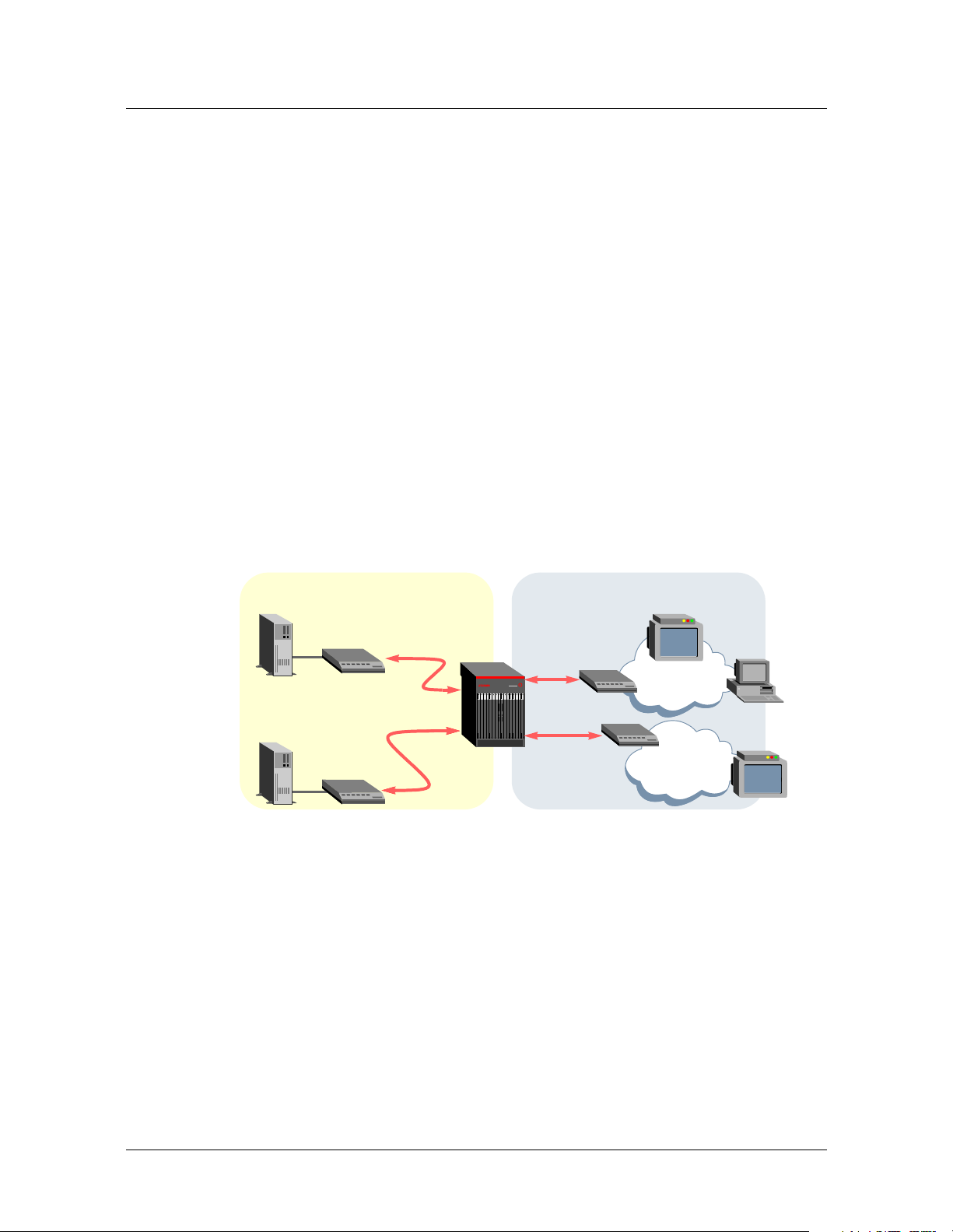
Multicast video
A Stinger IP2000 uses the Internet Group Management Protocol (IGMP) to manage
group memberships of downstream video to a PC application or set-top box, as
shown in Figure 1-1. Administrators can configure levels of service that control
subscribers’ access to specific multicast groups. Connection to originating router can
be across the Gigabit Ethernet interface or through a high-speed IP over ATM
connection.
Figure 1-1. Sample setup showing multicast and unicast video services
Network side User side
Multicast
video server
Multicast
router
Unicast video
server
IP router
Internet and voice access
When a subscriber has DSL Integrated Access Device (IAD) equipment (such as a
CellPipe®), the Stinger can deliver integrated voice and data services over the local
copper loop, providing a efficient, low-cost solution for enterprise, small business,
home office, and residential subscribers.
IP multicast
IP unicast
IP/ATM
IP/ATM
CPE
router
CPE
router
Set-top box (STB)
PC
NET-1
STB
NET-2
1-4 Stinger® IP2000 Configuration Guide
Page 23
Network architecture overview
Figure 1-2. Sample setup showing Internet access and voice over ATM
Network side User side
Welcome to the IP2000
Internet
ISP Voice
ATM
Voice
gateway
IP/ATM
IP/ATM
ATM
CPE
router
CellPipe
IAD
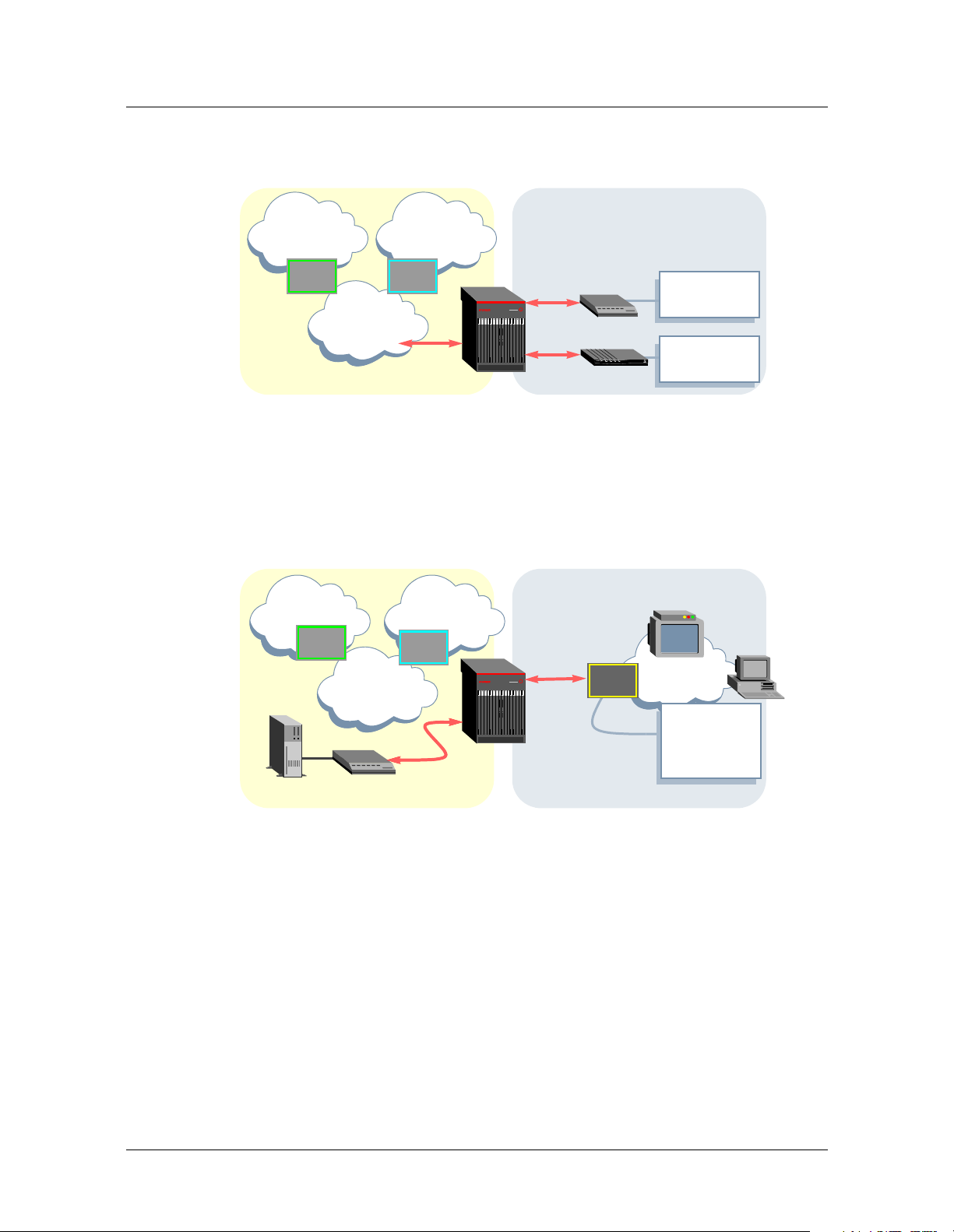
Multiplexing multiple IP flows on a single ATM VCC
A Stinger IP2000 supports an implementation of Class of Service (CoS) that co-exists
with the Stinger ATM QoS implementation. This feature allows transferring multiple
IP video streams (multicast and unicast) over single user-side ATM virtual circuit.
Figure 1-3. Sample setup showing multiple IP flows to a CPE router
Network side User side
Internet Voice
IAD
ISP
ATM
Multicast
router
Voice
gateway
IP multicast
IP/ATM
IP/ATM
Per-VC
priority
queueing
Services:
Internet access
Services:
Voice, Internet
access
Set-top box (STB)
NET-1
Services:
Multicast
video, VoATM,
Internet access
PC
The proprietary CoS implementation enables the delivery of differentiated services
over an IP infrastructure. All traffic handled by the IP2000, whether encapsulated IP
or native ATM, passes through the network processor function.
Non-IP terminated ATM traffic, including operations, administration, and
maintenance (OAM) F5 traffic, is treated as highest priority and handled in an AT M
pass-through mode. This traffic passes through the network processor with no further
processing.
RFC 1483 IP traffic that terminates on the IP2000 is reassembled from ATM cells into
IP packets. It is then classified and assigned to priority output queues. Per-VC strictpriority queuing is supported with three priority levels as described in Table 1-2.
Stinger® IP2000 Configuration Guide 1-5
Page 24

Welcome to the IP2000
Network architecture overview
Table 1-2. CoS and per-VC queueing for prioritizing IP packet processing
Priority queue Priority level Packet classification assigned to queue
1 High IP Control Protocol Classification
2 Medium Multicast Classification
3Low
Per-VC queuing operates in conjunction with the associated ATM shaping rate. The
aggregate rate of the combination of three priority queues (Class of Service Queuing
with Strict Priority) associated with a particular ATM virtual circuit is controlled by
the SCR (sustained cell rate) configured for the VC. In this case, SCR is configured
equal to PCR (peak cell rate). Rate information is configurable in the atm-qos profile
for each virtual circuit. For details about configuring ATM QoS, see the Stinger ATM
Configuration Guide.
■ ARP/RARP protocol messages
■ ICMP protocol messages
■ RIP protocol messages
■ IGMP protocol messages
■ IP multicast data
Unicast Classification
■ IP unicast data
1-6 Stinger® IP2000 Configuration Guide
Page 25

Gigabit Ethernet Configuration
Configuring the physical and logical interface . . . . . . . . . . . . . . . . . . . . . . . . . . . 2-1
Verifying the Gigabit Ethernet interface setup . . . . . . . . . . . . . . . . . . . . . . . . . . . 2-3
Gigabit Ethernet port redundancy . . . . . . . . . . . . . . . . . . . . . . . . . . . . . . . . . . . . 2-5
Administrative tools for Gigabit Ethernet . . . . . . . . . . . . . . . . . . . . . . . . . . . . . . 2-9
The IP2000 controller has two Ethernet interfaces, one 10/100 BASE-T interface for
management access to the unit via Telnet or SNMP, and one Gigabit Ethernet
interface for high-speed access to a local IP subnet. For information about configuring
the management interface, see the Getting Started Guide for your Stinger platform.
The Gigabit Ethernet MAC (GMAC) physical interface operates only in full-duplex
mode only for a full 1Gbps throughput. It supports auto-negotiation for advertising
its rate and duplex mode, but not for renegotiating it on the IEEE 802 LAN.
Stinger units with redundant IP2000 controllers can be configured to enable Gigabit
Ethernet port redundancy. With proper configuration, RFC 1483 (MPoA)
connections, VLAN connections, and MBONE interface functions can be maintained
across Gigabit Ethernet following a controller switchover.
2
Configuring the physical and logical interface
The system creates configuration profiles for both IP2000 Ethernet interfaces. For
each controller, interface 1 is always the 10/100 BASE-T management interface, and
interface 2 is the Gigabit Ethernet interface. For example:
admin> dir ethernet
18 07/11/2003 13:55:31 { shelf-1 first-control-module 1 }
24 07/11/2003 19:34:41 { shelf-1 first-control-module 2 }
18 07/11/2003 13:55:31 { shelf-1 second-control-module 1 }
24 07/11/2003 13:57:32 { shelf-1 second-control-module 2 }
admin> dir ip-interface
21 07/11/2003 13:55:31 { { any-shelf any-slot 0 } 0 }
31 07/11/2003 22:46:34 { { shelf-1 first-control-module 1 } 0 }
21 07/11/2003 13:57:01 { { shelf-1 first-control-module 2 } 0 }
21 07/11/2003 13:55:31 { { shelf-1 second-control-module 1 } 0 }
21 07/11/2003 13:57:01 { { shelf-1 second-control-module 2 } 0 }
Stinger® IP2000 Configuration Guide 2-1
Page 26

Gigabit Ethernet Configuration
Configuring the physical and logical interface
Viewing ethernet profile settings
To configure the data-link functions of the Gigabit Ethernet interface, open the
ethernet profile. For example:
admin> read ethernet { 1 8 2 }
admin> list
[in ETHERNET/{ shelf-1 first-control-module 2 }]
interface-address* = { shelf-1 first-control-module 2 }
link-state-enabled = no
enabled = yes
ether-if-type = fiber
bridging-enabled = no
filter-name = ""
duplex-mode = full-duplex
pppoe-options = { no no }
bridging-options = { 0 no no }
media-speed-mbit = 1000mb
auto-negotiate = no
For details about each of the parameters shown above, see the Stinger Reference.
Following are some Gigabit Ethernet-specific notes about the profile contents:
Parameter Notes about Gigabit Ethernet settings
interface-address*
link-state-enabled
enabled
ether-if-type
bridging-enabled
filter-name
duplex-mode
pppoe-options
The profile index and interface-address value of the
profile for a Gigabit Ethernet interface always specifies
an interface number of 2. For example:
shelf-1 first-control-module 2
With the default value, the system discards packets and
does not choose an alternate route if the interface is
down. If you set this to yes, the system deletes routes to
the interface when the interface is unavailable, and
then restores the routes when the interface becomes
available again.
If you set this to no and write the profile, the interface is
unavailable.
This setting is read-only and specifies either fiber or
utp (CAT5 unshielded twisted pair).
Enable/disable LAN packet bridging on the interface.
Set this parameter to yes to enable bridging on the
Gigabit Ethernet port. This is required for VLAN
operations. See Chapter 3, “VLAN Configuration.”
Applies a data filter to the interface. See Chapter 10,
“Filter Configuration.”
This setting is read-only and specifies full-duplex mode.
Not used by the IP2000.
2-2 Stinger® IP2000 Configuration Guide
Page 27

Parameter Notes about Gigabit Ethernet settings
bridging-options
media-speed-mbit
auto-negotiate
Not used by the IP2000. If you are configuring VLANs, you
set bridging options in the vlan-ethernet profile (not
in the ethernet profile). For details, see Chapter 3,
“VLAN Configuration.”
This setting is read-only and specifies 1Gbps.
Setting this parameter to yes does not cause the IP2000
to negotiate its duplex mode or speed, but it does cause
the system to advertise a full-duplex 1Gbps port , which
helps to ensure compatibility with remote Gigabit
Ethernet interfaces that support autonegotiation.
Modifying default ethernet settings
With the default settings, the Gigabit Ethernet interface is fully operational. The
following commands enable autonegotiation, to help ensure compatibility with other
Gigabit Ethernet interfaces that can negotiate between full-duplex and half-duplex
operations. (The IP2000 Gigabit Ethernet always operates in full-duplex mode.)
admin> read ethernet { 1 8 2 }
admin> set auto-negotiate = yes
admin> write -f
Gigabit Ethernet Configuration
Verifying the Gigabit Ethernet interface setup
Assigning an IP address in the ip-interface profile
For details about the ip-interface profile, and about enabling dynamic routing or
configuring static routes to enable the system to communicate beyond its own
subnet, see “Configuring ip-interface profiles for Ethernet ports” on page 4-6. The
following commands provide the minimal configuration of an IP address for the
Gigabit Ethernet interface:
admin> read ip-interface { { 1 8 2 } 0 }
admin> set ip-address = 10.99.99.101/24
admin> write -f
Verifying the Gigabit Ethernet interface setup
After you assign an IP address, you can verify that the Gigabit Ethernet interface is
able to handle IP traffic by checking some command output. For details about the
netstat and gmac commands, see the Stinger Reference.
You can also use the debug-level ifmgr -d command to verify that the Gigabit
Ethernet interface is active. This is described in Appendix A, “IP2000 Diagnostics.”
Checking the routing table
The following command output verifies that the routing table has an entry for the
Gigabit Ethernet interface (IP address 100.1.1.3/32):
admin> netstat -rn
Destination Gateway IF Flg Pref Met Use Age
0.0.0.0/0 1.1.2.1 ie0 SGP 60 1 3817 828
Stinger® IP2000 Configuration Guide 2-3
Page 28

Gigabit Ethernet Configuration
Verifying the Gigabit Ethernet interface setup
20.1.2.0/24 - ie1-1 C 0 0 0 828
20.1.2.3/32 - local CP 0 0 0 828
100.1.1.0/8 - ie1 C 0 0 4683 828
100.1.1.3/32 - local CP 0 0 1580 828
127.0.0.0/8 - bh0 CP 0 0 0 828
127.0.0.1/32 - local CP 0 0 0 828
127.0.0.2/32 - rj0 CP 0 0 0 828
1.1.2.0/24 - ie0 C 0 0 1428 828
1.1.2.65/32 - local CP 0 0 2937 828
224.0.0.0/4 - mcast CP 0 0 0 828
224.0.0.1/32 - local CP 0 0 0 828
224.0.0.2/32 - local CP 0 0 0 828
224.0.0.9/32 - local CP 0 0 0 828
255.255.255.255/32 - ie0 CP 0 0 0 828
Verifying the network processor setup for the interface
The network processor on the IP2000 creates a connection entry for the Gigabit
Ethernet interface when the interface becomes operational. You can force the
network processor to create a connection entry for the Gigabit Ethernet interface by
using the following command:
admin> gmac -n
NP setup for gmac done.
Verifying the SAR setup for the interface
The Stinger Segmentation and Reassembly (SAR) creates an ATM connection entry
for the Gigabit Ethernet interface. You can force the SAR setup by using the following
command:
admin> gmac -s
GMAC: SAR conn. open with vpi = 0, vci = 200
Verifying IP packet transfer on the interface
The following command clears statistics gathered on the Gigabit Ethernet interface:
admin> gmac -d -c
The next command pings a host on the same subnet as the Gigabit Ethernet interface:
admin> ping 100.1.1.10
PING 100.1.1.10 (100.1.1.10): 56 data bytes
64 bytes from 100.1.1.10: icmp_seq=0 ttl=255 time=0 ms
64 bytes from 100.1.1.10: icmp_seq=1 ttl=255 time=0 ms
64 bytes from 100.1.1.10: icmp_seq=2 ttl=255 time=0 ms
64 bytes from 100.1.1.10: icmp_seq=3 ttl=255 time=0 ms
64 bytes from 100.1.1.10: icmp_seq=4 ttl=255 time=0 ms
64 bytes from 100.1.1.10: icmp_seq=5 ttl=255 time=0 ms
64 bytes from 100.1.1.10: icmp_seq=6 ttl=255 time=0 ms
64 bytes from 100.1.1.10: icmp_seq=7 ttl=255 time=0 ms
--- 100.1.1.10 ping statistics --8 packets transmitted, 8 packets received, 0% packet loss
round-trip min/avg/max = 0/0/0 ms
2-4 Stinger® IP2000 Configuration Guide
Page 29

Gigabit Ethernet Configuration
Gigabit Ethernet port redundancy
The following command displays GMAC statistics that show packet transfer. The
txGoodPackets and rxGoodPackets fields in the command output show 8 packets
transmitted and received in the ICMP sequence shown immediately above. For more
details on the command output fields, see “Total transmit statistics” on page A-24 and
“Total receive statistics” on page A-26.
admin> gmac -d
Gigabit Ethernet port statistics :
txOctetsLow = 816
txOctetsHigh = 0
txGoodPackets = 8
txPkt64 = 0
txPkt65127 = 8
txPkt128255 = 0
txPkt256511 = 0
txPkt5121023 = 0
txPkt1024Max = 0
txPktDefer = 0
txPktUndSz = 0
txUnderFlow = 0
txPfcf = 0
txPfcc = 0
txRfcf = 0
txRfcc = 0
txOverFlow = 0
txAlmostFull = 0
rxOctetsLow = 816
rxOctetsHigh = 0
rxGoodPackets = 8
rxPkt64 = 0
rxPkt65127 = 8
rx128255 = 0
rx256511 = 0
rx5121023 = 0
rx1024Max = 0
rxMacType = 0
rxCrcErrors = 0
rxUnderSize = 0
rxOverSize = 0
rxAlmostFull = 0
rxOverRun = 0
rxMulticastPackets = 0
rxBroadcastPackets = 0
rxJabber = 0
rxPfc = 0
rxRfc = 0
Gigabit Ethernet port redundancy
With the proper configuration, systems with redundant controllers support Gigabit
Ethernet redundancy, which enables the system to maintain RFC 1483 (MPoA)
Stinger® IP2000 Configuration Guide 2-5
Page 30

Gigabit Ethernet Configuration
Gigabit Ethernet port redundancy
connections, VLAN connections, and LAN MBONE interface functions across a
controller switchover.
Note A soft IP interface configuration is required for Gigabit Ethernet redundancy of
RFC 1483 connections and a LAN MBONE interface.
Configuring a soft IP interface for Gigabit Ethernet redundancy
The soft IP interface is an internal interface that is not associated with a specific
physical port, but that can be accessed through the Ethernet interface of whichever
controller is primary. For background information, see “Defining a soft interface for
increased accessibility” on page 4-8.
The system creates one soft interface profile by default. For example:
admin> dir ip-interface
35 07/10/2003 11:26:10 { { any-shelf any-slot 0 } 0 }
35 07/10/2003 11:26:10 { { shelf-1 first-control-module 1 } 0 }
38 07/10/2003 11:26:11 { { shelf-1 first-control-module 2 } 0 }
35 07/10/2003 11:26:10 { { shelf-1 second-control-module 1 } 0 }
38 07/10/2003 11:26:11 { { shelf-1 second-control-module 2 } 0 }
You can use the default soft IP interface { {0 0 0 } 0 } for Gigabit Ethernet
redundancy. However, if you have already used the default profile for the soft IP
address of the 10/100M base Ethernet management ports, you can create another
soft IP interface using a profile index of { { 0 0 0 } x }, as long as the IP address in
that profile is on the same subnet as the Gigabit Ethernet ports.
Note The system associates its Ethernet interfaces with a particular soft address
based on the subnet assignment. The IP interface address of the Gigabit Ethernet
ports on the primary and secondary controllers and the soft IP interface address must
be on the same subnet.
Configuring Gigabit Ethernet redundancy for RFC 1483 connections
Figure 2-1 shows a Stinger with redundant IP2000 controllers. The Gigabit Ethernet
port in slot 8 ({ { 1 8 2 } 0 }), the Gigabit Ethernet port in slot 9 ({ { 1 9 2 } 0 }),
and the soft IP interface ({ { 0 0 0 } 1 }), all have IP address assignments on the
same subnet. In addition, the external router has a routing table entry that specifies
the soft IP interface address as the gateway to the CPE router destination.
Figure 2-1. Gigabit Ethernet redundancy for RFC 1483 connectivity
{ { 0 0 0 } 1 }
10.99.99.100/24
External
router
add route:
destination=10.14.16.1/24
gateway=10.99.99.100/24
IP
{ { 1 8 2 } 0 }
10.99.99.101/24
{ { 1 9 2 } 0 }
10.99.99.201/24
IP/ATM
CPE
router
10.14.16.1/24
The following commands configure the Gigabit Ethernet port in slot 8:
admin> read ip-interface { { 1 8 2 } 0 }
admin> set ip-address = 10.99.99.101/24
2-6 Stinger® IP2000 Configuration Guide
Page 31

Gigabit Ethernet Configuration
Gigabit Ethernet port redundancy
admin> write -f
The next commands configure the Gigabit Ethernet port on slot 9:
admin> read ip-interface { { 1 9 2 } 0 }
admin> set ip-address = 10.99.99.201/24
admin> write -f
The following commands configure a soft IP interface on the same subnet:
admin> new ip-interface { { 0 0 0 } 1 }
admin> set ip-address = 10.99.99.100/24
admin> write -f
When you write the profile of the soft interface, the system displays a message:
LOG notice, Shelf 1, Controller-1, Time: 11:42:57-Soft ip will be effective if the ip-addr of primary controller is
configured.
To ensure that the external router can reach the CPE router in Figure 2-1, the
external router must specify the soft IP address as the gateway to the CPE router
destination address. For example,
destination-address = 10.14.16.1/24
gateway-address = 10.99.99.100/24
Configuring Gigabit Ethernet redundancy for VLAN bridge circuits
Virtual LAN (VLAN) technology is supported with an optional software license. For
details about configuring VLAN, see Chapter 3, “VLAN Configuration.”
A VLAN bridge circuit is a pairing between a unique VLAN ID on the Gigabit Ethernet
port and a DSL subscriber connection on a LIM port. To enable the system to
maintain the pairing following a controller switchover, you must configure the VLAN
circuits using the expression any-slot or 0 as the slot number.
For example, the following commands create a new GigE-redundant VLAN bridge
circuit with VLAN ID 300.
admin> new vlan-ethernet { { 1 0 2 } 300 }
admin> set enabled = yes
admin> set bridging-options bridging-group = 300
admin> set bridging-options bridge = yes
admin> write -f
To modify an existing VLAN bridge circuit for Gigabit Ethernet redundancy, you must
create a new configuration and then delete the old one. For example, the following
command shows an existing VLAN bridge circuit with VLAN ID 50:
admin> dir vlan
37 07/21/2003 17:38:24 { { shelf-1 first-control-module 2 } 50 }
The next commands modify the VLAN bridge circuit to enable Gigabit Ethernet
redundancy for the connection:
admin> read vlan { { 1 8 2 } 50 }
Stinger® IP2000 Configuration Guide 2-7
Page 32

Gigabit Ethernet Configuration
Gigabit Ethernet port redundancy
admin> set interface-address = { { 1 0 2 } 50 }
(New index value; will save as new profile VLAN-ETHERNET/{ { shelf-1
any-slot 2} 50 }.)
admin> write -f
The following commands list and then delete the older vlan-ethernet profile:
admin> dir vlan
37 07/15/2003 09:00:30 { { shelf-1 any-slot 2 } 50 }
37 07/21/2003 17:38:24 { { shelf-1 first-control-module 2 } 50 }
admin> delete vlan { {1 8 2 } } 50}
Delete profile VLAN-ETHERNET/{ { shelf-1 first-control-module 2 } 50 }?
[y/n] y
VLAN-ETHERNET/{ { shelf-1 first-control-module 2 } 50 } deleted
Configuring a redundant LAN MBONE
IP multicast forwarding is supported with an optional software license. For details
about configuring it, see Chapter 8, “IP Multicast Configuration.”
To support redundancy for a LAN MBONE interface, you must configure a soft IP
interface for the Gigabit Ethernet ports, enable multicast on both ports, and use the
any-slot expression in the mbone-lan-interface parameter setting.
Figure 2-2 shows a Stinger with redundant IP2000 controllers. The Gigabit Ethernet
port in slot 8 ({ { 1 8 2 } 0 }), the Gigabit Ethernet port in slot 9 ({ { 1 9 2 } 0 }),
and the soft IP interface ({ { 0 0 0 } 1 }), all have IP address assignments on the
same subnet and both physical ports enable multicast.
Figure 2-2. Gigabit Ethernet redundancy for a LAN MBONE
Multicast
video servers
MBONE
routers
IP
{ { 0 0 0 } 1 }
10.99.99.100/24
{ { 1 8 2 } 0 }
10.99.99.101/24
{ { 1 9 2 } 0 }
10.99.99.201/24
Stinger IP2000
Multicast client interfaces
(LIM ports)
The following commands configure the Gigabit Ethernet port in slot 8:
admin> read ip-interface { { 1 8 2 } 0 }
admin> set ip-address = 10.99.99.101/24
admin> set multicast-allowed = yes
admin> write -f
The next commands configure the Gigabit Ethernet port on slot 9:
admin> read ip-interface { { 1 9 2 } 0 }
admin> set ip-address = 10.99.99.201/24
admin> set multicast-allowed = yes
admin> write -f
2-8 Stinger® IP2000 Configuration Guide
Page 33

Gigabit Ethernet Configuration
Administrative tools for Gigabit Ethernet
The following commands configure a soft IP interface on the same subnet:
admin> new ip-interface { { 0 0 0 } 1 }
admin> set ip-address = 10.99.99.100/24
admin> write -f
The following commands enable the multicast forwarding function and specify a
redundant LAN MBONE configuration:
admin> read ip-global
admin> set multicast-forwarding = yes
admin> set multiple-mbone mbone-lan-interface 1 = { { 1 0 2 } 0 }
admin> write -f
admin> list multiple-mbone mbone-lan-interface
[in IP-GLOBAL:multiple-mbone:mbone-lan-interface]
mbone-lan-interface[1] = { { shelf-1 any-slot 2 } 0 }
mbone-lan-interface[2] = { { any-shelf any-slot 0 } 0 }
mbone-lan-interface[3] = { { any-shelf any-slot 0 } 0 }
mbone-lan-interface[4] = { { any-shelf any-slot 0 } 0 }
Note With this configuration, the LAN MBONE is supported on the Gigabit Ethernet
port of the controller in slot 8 or slot 9, whichever is primary. Following a switchover,
each IGMP client must rejoin its group to receive multicast traffic.
Administrative tools for Gigabit Ethernet
The system supports the gmac command for administrative information about Gigabit
Ethernet ports. If you are managing the system remotely, some of this information is
also available through the ip2kstats MIB. For details, see “Gigabit Ethernet
diagnostics” on page A-2 and “SNMP MIB for GMAC and VLAN statistics” on
page A-23. For other commands that can be used to monitor activity on any Ethernet
port, such as etherdisplay, see the Stinger Reference.
Stinger® IP2000 Configuration Guide 2-9
Page 34

Page 35

VLAN Configuration
The IP2000 VLAN implementation . . . . . . . . . . . . . . . . . . . . . . . . . . . . . . . . . . . 3-1
Configuring a VLAN bridge circuit . . . . . . . . . . . . . . . . . . . . . . . . . . . . . . . . . . . . 3-3
Configuring a local management VLAN. . . . . . . . . . . . . . . . . . . . . . . . . . . . . . . . 3-6
Administrative tools for VLAN . . . . . . . . . . . . . . . . . . . . . . . . . . . . . . . . . . . . . . . 3-8
Virtual LAN (VLAN) technology is supported with an optional software license.
VLANs are defined in IEEE standard 802.1Q (1998) for Local and Metropolitan Area
Networks: Virtual Bridged Local Area Networks.
VLANs are typically used for making physically separate nodes appear as if they are
part of a LAN. A VLAN helps to divide a network into separate broadcast domains
without the latency problems typically seen in routed networks, and without
modifying the physical topology. VLANs also allow a network administrator to group
users logically irrespective of where they are located physically.
Enter the following command to determine whether the VLAN license is enabled:
admin> get base vlan
[in BASE]
vlan-enabled = yes
3
The system sets this parameter to yes when the VLAN license is enabled. If the license
is not enabled, the system displays an error message if you configure VLAN
capabilities. For information about obtaining and enabling Lucent Technologies
software licenses, contact your Lucent sales representative.
The IP2000 VLAN implementation
The IP2000 VLAN implementation can support up to 4096 VLAN IDs on the Gigabit
Ethernet port. For full compatibility with IEEE 802.1Q standard, however, Lucent
recommends that you do not use 0 or 4095 as VLAN IDs. As a result, as many as 4093
logically separate VLAN IDs are supported.
In compliance with IEEE 802.1Q, the Stinger adds 4-byte tags to the header of each
Ethernet frame. The tags contain a VLAN ID and IEEE 802.1P priority information.
Most Ethernet switches and routers can use these tags to direct the frames only to the
specified VLAN. Typically, each VLAN ID on the Gigabit Ethernet interface is paired to
form a bridge circuit with one DSL interface. However, management VLANs, used for
SNMP or Telnet access from the LAN to the system itself, can also be configured with
the current software.
Stinger® IP2000 Configuration Guide 3-1
Page 36

VLAN Configuration
The IP2000 VLAN implementation
VLAN bridge circuits
A VLAN bridge circuit is a pairing between a unique VLAN ID on the Gigabit Ethernet
port and a DSL subscriber connection on a LIM port. The transfer of traffic between
the two interfaces within the Stinger unit occurs at Layer 2. The Stinger does not
examine Layer 3 information within the data stream.
You create a VLAN bridge circuit by specifying the same bridging-group number in
both the vlan-ethernet and connection (or RADIUS) user profile. This is illustrated
in Figure 3-1.
Figure 3-1. Bridge circuit between a virtual LAN and bridged WAN interface
Network side User side
IP
[in VLAN-ETHERNET:bridging-options]
bridging-group = 450
When you configure a bridging group, the system creates a separate bridging table
that contains only interfaces that share the same group number. When a packet is
received on an interface in a bridging group, the system consults only that table for
destination interfaces. It will not forward the traffic to interfaces that are not in the
same bridging group.
Note With the current software, you cannot bridge multiple LIM-side PVCs in the
same system to the same VLAN ID.
Local management VLANs
You can configure a virtual IP interface as a management VLAN, which terminates on
the control module and provides access to the system via Telnet or SNMP through the
Gigabit Ethernet interface. The system supports up to 16 virtual IP interfaces. For
details, see “Defining a local virtual IP interface” on page 4-8.
A management VLAN is not paired with a WAN interface. It is typically used solely
for management access to the Stinger unit, as shown in Figure 3-2.
Gigabit
Ethernet
IP/ATM
[in CONNECTION:bridging-options]
bridging-group = 450
CPE router
Figure 3-2. Management VLAN terminating in the Stinger unit
PC
IP
[in IP-INTERFACE]
vlan-enabled = yes
vlan-id = 2000
3-2 Stinger® IP2000 Configuration Guide
Page 37

Note You can also enable multicast forwarding on the VLAN interface, to allow the
interface to handle both management and multicast traffic. For details about that
configuration, see “Configuring MBONE interfaces” on page 8-3.
Configuring a VLAN bridge circuit
To configure a VLAN bridge circuit, you must complete the following steps:
1 Verify that bridging is enabled in the ethernet profile for the Gigabit Ethernet
interface. For background information, see Chapter 2, “Gigabit Ethernet
Configuration.”
2 Create a vlan-ethernet profile with a unique VLAN ID and bridging-group
number.
3 Configure a connection or RADIUS profile that specifies the same bridging-
group number associated with the VLAN ID.
Note For Stinger systems with redundant controllers, you can configure Gigabit
Ethernet redundancy to enable the system to maintain VLAN operations across a
controller switchover. For details, see “Configuring Gigabit Ethernet redundancy for
VLAN bridge circuits” on page 2-7.
VLAN Configuration
Configuring a VLAN bridge circuit
Overview of VLAN configuration settings
You define a VLAN in a vlan-ethernet profile, which must specify a unique VLAN
ID from 0 to 4095, and a bridging-group number.
Note To maintain full compatibility with the IEEE 802.1Q standard, Lucent
recommends that you do not assign the VLAN ID values of 0, 1 and 4095. However,
the system does not prevent you from assigning these values.
You associate a VLAN ID with a DSL interface by specifying the same bridging-group
number in the vlan-ethernet profile and a connection or RADIUS profile. With the
current software, a VLAN bridge circuit can contain only two interfaces. You cannot
map multiple DSL interfaces to the same VLAN ID in the same Stinger unit.
Configuring vlan-ethernet settings
The index of a vlan-ethernet profile specifies the physical address of the Gigabit
Ethernet port and a unique VLAN ID. Following are the profile contents, shown for
VLAN ID 50:
[in VLAN-ETHERNET/{ { shelf-1 first-control-module 2 } 50 }]
interface-address* = { { shelf-1 first-control-module 2 } 50 }
vlan-id = 50
enabled = no
filter-name = ""
pppoe-options = { no no }
[in VLAN-ETHERNET/{ { shelf-1 first-control-module 2 } 50}:bridging-options]
bridging-group = 0
bridge = no
dial-on-broadcast = no
Stinger® IP2000 Configuration Guide 3-3
Page 38

VLAN Configuration
Configuring a VLAN bridge circuit
Parameter Setting
interface-address
vlan-id
enabled
filter-name
pppoe-options
bridging-options:
bridging-group
bridging-options:
bridge
dial-on-broadcast
Address of the Gigabit Ethernet port followed by the
VLAN ID, using the following format:
{ shelf-n slot-n port-n } vlan-id }
The slot-n is 8 (for the first control module) or 9 (the
second control module), and port-n is 2 for the Gigabit
port. The vlan-id value is the IEEE 802.1Q VLAN tag
value added to the IP packets transmitted on the Gigabit
Ethernet interface. The valid range is from 0 to 4095,
but for full compatibility with IEEE 802.1Q, Lucent
recommends that you do not use the vlan-id values of
0, 1 or 4095.
VLAN ID. This setting is read-only. You must set it in
the index of the vlan-ethernet profile.
Enable/disable the vlan-ethernet profile.
Not used by the IP2000.
Not used by the IP2000.
A group number (from 0 to 65535) for the bridge circuit
between the VLAN and a WAN interface. The bridging-
group parameter in this profile must match the
bridging-group parameter in the connection profile
that the vlan-id maps to.
Enable/disable WAN packet bridging on the interface.
With WAN bridging, the system can provide a
connection between segments that are connected by a
telecommunications link. Set this parameter to yes to
enable WAN bridging.
Not used by the IP2000.
Configuring DSL subscriber bridging-options settings
To pair a DSL interface with a VLAN ID, the connection or RADIUS profile must
enable bridging and specify the right ID for the destination VLAN. The far-end device
can be an IP router or a bridge. It is only within the Stinger unit that the VLAN ID is
inserted in the packet stream and the bridging occurs to the Gigabit Ethernet
interface.
For information about configuring a PVC to an IP router, see “Configuring IP
connection interfaces for CPE devices” on page 4-30. For information about ATM
PVCs, see the Stinger ATM Configuration Guide.
In addition to the usual settings, you must also specify the following parameters,
shown with default settings, in the DSL interface connection profile:
[in CONNECTION/"":bridging-options]
bridging-group = 0
bridge = no
dial-on-broadcast = no
3-4 Stinger® IP2000 Configuration Guide
Page 39

Parameter RADIUS attribute Setting
bridging-group Ascend-BIR-Bridge-
Group (7)
Number from 0 to 65535, used to group this subscriber
interface with a VLAN. Note that you cannot group
multiple LIM-side PVCs in the same system with the
same VLAN.
bridge
dial-on-broadcast
Ascend-Bridge (230) Enable/disable WAN packet bridging on the interface.
N/A Not used by the IP2000.
Enabling bridging on the Gigabit Ethernet interface
You must enable bridging on the Gigabit Ethernet port once, to provide bridging
support for all configured VLAN IDs. For details about the other settings in the
ethernet profile, see Chapter 2, “Gigabit Ethernet Configuration.”
The following commands enable bridging on the physical interface:
admin> read ethernet { 1 8 2 }
admin> set bridging-enabled = yes
admin> write -f
VLAN Configuration
Configuring a VLAN bridge circuit
Sample VLAN bridge circuit configuration
In the sample setup shown in Figure 3-3, the remote side of the VLAN bridge circuit
connects to a CPE on a remote office LAN. The Gigabit Ethernet side connects to a
router that can access the LAN of the head office.
Figure 3-3. Sample VLAN bridge circuit
Network side User side
Gigabit
Head Office
Network
In this sample setup, the Stinger receives traffic from the CPE, packetizes it and
inserts the VLAN ID in Ethernet frame headers, and bridges the packet stream across
its Gigabit Ethernet port. It does not terminate the packets by passing them up to the
IP router software.
The external router on the Gigabit Ethernet network interprets the VLAN ID and
directs the packet stream at Layer 2 to the specified VLAN, which is the head office
network.
First, verify that bridging is enabled on the physical interface.
Ethernet
IP/ATM
PC
Remote Office
Network
Then, create a vlan-ethernet profile. The following commands configure the Gigabit
Ethernet side of the VLAN bridge circuit with vlan-id 50 and the bridging-group
number 34590:
admin> new vlan-ethernet { { 1 8 2 } 50}
admin> set enabled = yes
Stinger® IP2000 Configuration Guide 3-5
Page 40

VLAN Configuration
Configuring a local management VLAN
admin> set bridging-options bridging-group = 34590
admin> write -f
Then create a onnection profile on that interface for the LIM side of the VLAN bridge
circuit. The following commands create a connection profile for the { 1 2 1 } LIM
interface (nailed group 51):
admin> new connection dslcpe
admin> set active = yes
admin> set encapsulation-protocol = atm
admin> set bridging-options bridging-group = 34590
admin> set bridging-options bridge = yes
admin> set atm-options vpi = 8
admin> set atm-options vci = 100
admin> set atm-options nailed-group = 51
admin> write -f
Following is a comparable RADIUS profile for the LIM interface side of the VLAN
bridge circuit:
permconn-st-1 Password = "ascend"
Service-Type = Outbound,
Framed-Protocol = ATM-1483,
User-Name = "dslcpe",
Ascend-Route-IP = Route-IP-Yes,
Ascend-ATM-Group = 51,
Ascend-ATM-Vpi = 8,
Ascend-ATM-Vci = 100,
Ascend-Bridge = Bridge-Yes,
Ascend-BIR-Bridge-Group = 34590
The LAN session should come up, displaying log messages such as the following:
LOG notice, Shelf 1, Slot 2, Time: 20:24:02-Line 1 up
LOG info, Shelf 1, Controller-1, Time: 20:24:02-[1/2/1/0] Assigned to port [MBID 1]
LOG info, Shelf 1, Slot 2, Time: 20:24:02-[1/2/1/0] LAN session up: <dslcpe> [MBID 1] [dslcpe]
The following command shows the active session:
admin> users
SessionID Line/Chan Slot:Item Tx/Rx Rate Svc Address Username
385031879 1.02.01/000 1:02:01/000 8000K/832K ATM 0.0.0.0 dslcpe
<end user list> 1 active user(s)
For information about low-level diagnostic commands for viewing bridge tables, see
Appendix A, “IP2000 Diagnostics.”
Configuring a local management VLAN
You can configure a virtual IP interface as a management VLAN, to isolate
management traffic and provide additional security for the logins to the system. Like
3-6 Stinger® IP2000 Configuration Guide
Page 41

any VLAN configuration, this requires that bridging is enabled on the Gigabit
Ethernet interface. For details, see “Enabling bridging on the Gigabit Ethernet
interface” on page 3-5.
Overview of ip-interface VLAN settings
Following are the parameters, shown with default settings for a virtual IP interface,
for configuring a management VLAN:
[in IP-INTERFACE/{ { shelf-1 first-control-module 2 } 1 }]
interface-address* = { { shelf-1 first-control-module 2 } 1 }
ip-address = 0.0.0.0/0
vlan-enabled = no
vlan-id = 0
s
Parameter Setting
interface-address
ip-address
vlan-enabled
vlan-id
Address of the Gigabit Ethernet interface followed by
the virtual IP interface number, using the following
format:
{ shelf-n slot-n port-n } item-n }
The slot-n is 8 (for the first control module) or 9 (the
second control module), and port-n is 2 for the Gigabit
port. The item-n value is a number from 1 to 16,
identifying the virtual IP interface.
IP address of the virtual IP interface
Enable/disable IEEE 802.1Q VLAN tagging on the
virtual IP interface.
VLAN ID for this virtual interface. This is the IEEE
802.1Q tag value to be added to the IP packets
transmitted on the virtual interface. The valid range is
from 0 to 4095, but for full compatibility with IEEE
802.1Q, Lucent recommends that you do not use the
vlan-id values of 0, 1 or 4095.
VLAN Configuration
Configuring a local management VLAN
Sample management VLAN configuration
In the sample setup shown in Figure 3-4, the IP2000 Gigabit Ethernet interface
supports a switch configured with a VLAN ID of 100. For information about
displaying the VLAN interface after creating it, see the ifmgr command in
Appendix A, “IP2000 Diagnostics.”
Figure 3-4. Sample management VLAN
TFTP
server
IP
135.1.2.3
Stinger® IP2000 Configuration Guide 3-7
External
switch
VLAN ID 100
20.1.2.10
Gigabit
Ethernet
20.1.2.3
Page 42

VLAN Configuration
Administrative tools for VLAN
First, verify that bridging is enabled on the physical interface.
Then, create a virtual IP interface of the Gigabit Ethernet port and configure it as a
management VLAN. For example:
admin> read ip-interface { { 1 8 2 } 1 }
admin> set ip-address = 20.1.2.3/24
admin> set vlan-enabled = yes
admin> set vlan-id = 100
admin> write -f
While logged into the Stinger unit, you should be able to ping the external switch:
admin> ping 20.1.2.10
PING 20.1.2.10 (20.1.2.10): 56 data bytes
64 bytes from 20.1.2.10: icmp_seq=0 ttl=255 time=10 ms
64 bytes from 20.1.2.10: icmp_seq=1 ttl=255 time=0 ms
64 bytes from 20.1.2.10: icmp_seq=2 ttl=255 time=0 ms
64 bytes from 20.1.2.10: icmp_seq=3 ttl=255 time=0 ms
64 bytes from 20.1.2.10: icmp_seq=4 ttl=255 time=0 ms
64 bytes from 20.1.2.10: icmp_seq=5 ttl=255 time=0 ms
64 bytes from 20.1.2.10: icmp_seq=6 ttl=255 time=0 ms
64 bytes from 20.1.2.10: icmp_seq=7 ttl=255 time=0 ms
^C
--- 20.1.2.10 ping statistics --8 packets transmitted, 8 packets received, 0% packet loss
round-trip min/avg/max = 0/1/10 ms
The following commands set up a static route to reach the TFTP server across the
Gigabit Ethernet link:
admin> new ip-route tftp-server
admin> set dest-address = 135.1.2.3
admin> set gateway-address = 20.1.2.10
admin> write -f
You should now be able to download software from the TFTP server to the Stinger
flash memory:
admin> load cm-v2 n 135.1.2.3 stngrcm2.ffs
loading code from 135.1.2.3
file stngrcm2.ffs...
done.
Administrative tools for VLAN
Commands that provide administrative information about VLAN are available only in
the debug environment. If you are managing the system remotely, some of this
information is also available through the ip2kstats MIB. For details, see “VLAN-
related diagnostics” on page A-13 and “SNMP MIB for GMAC and VLAN statistics” on
page A-23.
3-8 Stinger® IP2000 Configuration Guide
Page 43

IP Router Configuration
Introduction to the IP router software . . . . . . . . . . . . . . . . . . . . . . . . . . . . . . . . . 4-1
Configuring ip-interface profiles for Ethernet ports. . . . . . . . . . . . . . . . . . . . . . . 4-6
Configuring ip-global network features . . . . . . . . . . . . . . . . . . . . . . . . . . . . . . . . 4-9
Configuring ip-route profiles . . . . . . . . . . . . . . . . . . . . . . . . . . . . . . . . . . . . . . . 4-28
Configuring IP connection interfaces for CPE devices . . . . . . . . . . . . . . . . . . . . 4-30
Configuring bridged IP routing (BIR) connection interfaces . . . . . . . . . . . . . . . 4-37
Administrative tools for IP routing. . . . . . . . . . . . . . . . . . . . . . . . . . . . . . . . . . . 4-43
This chapter describes IP routing features that are typically configured on a Stinger
IP2000. Some parameters in IP-related profiles are not used by the IP2000, or are not
relevant to its primary applications. Those parameters are not described in this
chapter, but are documented in the Stinger Reference.
4
Introduction to the IP router software
When you reset the system, an IP routing table is constructed that contains all the
routes known to the system, including the following:
■ Routes for the local Ethernet interfaces (configured ip-interface profiles)
■ Routes for active WAN IP sessions
■ Routes for inactive WAN IP sessions (configured connection profiles)
■ Routes defined in ip-route profiles or RADIUS route profiles
If the Routing Information Protocol (RIP) is enabled on one or more interfaces, the
system adds routes as it learns them from routing-update packets. In addition, the
system is continuously updating its routing table by adding routes for links that
become active and removing routes for inactive sessions. If a nailed connection goes
down, the system removes the route from its routing table.
Routes and interfaces
An IP route specifies a destination address, a gateway to the network, and an
interface that leads to the gateway. It can also specify metrics and other values
associated with the route.
Stinger® IP2000 Configuration Guide 4-1
Page 44

IP Router Configuration
Introduction to the IP router software
A route defined in a profile is a static route. A dynamic route is learned from RIP updates
sent by other routers. Dynamic updates provide access to many more routes than
those actually configured in the system, and are updated automatically as routes
change. However, dynamic updates cause additional routing overhead, so they are
disabled by default.
An interface is a point of ingress to or egress from the system. For example, a local
interface is an Ethernet port and a WAN interface is a nailed or switched connection.
An IP interface is the logical IP address that enables IP data to be sent and received.
Displaying the routing table
For details about the netstat command, see the Stinger Reference. The following
command displays the system’s routing table:
admin> netstat -r
Destination Gateway IF Flg Pref Met Use Age
0.0.0.0/0 1.112.26.1 ie0 SGP 60 1 343 2274
127.0.0.0/8 - bh0 CP 0 0 0 2274
127.0.0.1/32 - local CP 0 0 0 2274
127.0.0.2/32 - rj0 CP 0 0 0 2274
1.112.0.0/16 - ie0 C 0 0 6497 2274
1.112.26.146/32 - local CP 0 0 3635 2274
224.0.0.0/4 - mcast CP 0 0 179 2274
224.0.0.1/32 - local CP 0 0 0 2274
224.0.0.2/32 - local CP 0 0 0 2274
224.0.0.9/32 - local CP 0 0 0 2274
255.255.255.255/32- ie0 CP 0 0 61 2274
Total Routes = 11 Hidden Routes = 0
For each route in the table, the Destination and Gateway fields show the destination
address and the address of the next-hop router used to reach that destination. The
zero destination address is the default route. If the system does not find a route for a
packet’s destination, it forwards the packet to the default route rather than dropping
the packet. Note that the system uses the most specific route (having the longest
prefix) that matches a given destination. Direct routes do not show a gateway
address.
An asterisk (*) in the flags column indicates a hidden route, which is not included in
routing updates sent by the system and is not used for forwarding packets. Hidden
routes are used only for display purposes.
The IF field shows the name of the interface through which a packet addressed to the
entry’s destination will be sent. The route to the mcast interface name encapsulates
the multicast forwarder for the entire class D address space. (For more information,
see Chapter 8, “IP Multicast Configuration.”)
Routes to the local unit display the local interface name. Packets to the 224.0.0.1
and 224.0.0.2 interfaces can be multicast and received like normal multicast packets,
but upon receiving such a packet, the router does not forward it to another link layer
device. Effectively, these packets have a maximum transmission unit (MTU) of 1.
4-2 Stinger® IP2000 Configuration Guide
Page 45

Displaying the interface table
To display the interface table, use the –i option on the netstat command line:
admin> netstat -i
Name MTU Net/Dest Address Ipkts Ierr Opkts Oerr
ie0 1500 1.112.0.0/16 1.112.26.146 5542 0 1636 0
ie1 1500 - - 0 0 0 0
ie1-1 1500 - - 0 0 0 0
lo0 1500 127.0.0.1/32 127.0.0.1 1629 0 1629 0
rj0 1500 127.0.0.2/32 127.0.0.2 0 0 0 0
bh0 1500 127.0.0.3/32 127.0.0.3 0 0 0 0
wanabe 1500 127.0.0.3/32 127.0.0.3 0 0 0 0
local 65535 127.0.0.1/32 127.0.0.1 1892 0 1892 0
mcast 65535 224.0.0.0/4 224.0.0.0 180 0 180 0
tunnel0 1500 1.112.0.0/16 1.112.26.146 0 0 0 0
vr0_main 1500 1.112.26.146/32 1.112.26.146 0 0 0 0
sip0 65535 - - 0 0 0 0
The entries named ie0 or ieN-N-N[-N ] represent Ethernet interfaces. N-N-N-N
represents the shelf number, slot number, item number, and logical-item number of
the interface. When the logical-item number is zero (the physical interface), it does
not appear in the interface name. The same sequence of numbers forms the address
used to index the ip-interface profile. For example, the default profile for 1-8-2 is
indexed as follows:
ip-interface { { 1 8 2 } 0 }
IP Router Configuration
Introduction to the IP router software
When the logical-item number is not zero, it does appear in the interface name.
Again, the sequence of numbers is identical to the profile index. For example,
suppose an ip-interface profile has the following index:
ip-interface { { 1 8 2 } 3 }
This profile has the following interface name:
ie1-8-2-3
The other names in the interface table have the following significance:
■ The lo0 (loopback) interface is the local loopback.
■ The rj0 (reject) and bh0 (blackhole) interfaces are used in the pool-summary
feature.
■ The wanabe interface is an inactive RADIUS dial-out profile.
■ The local interface is the local machine.
■ The mcast interface is the multicast interface, which represents the multicast
forwarder for the entire class D address space. For details, see Chapter 8, “IP
Multicast Configuration.”
■ The tunnel interface is a single pseudo-interface that is used only when the system
is terminating tunnels. (The number terminating the tunnel interface name is an
internal number that can change from one software version to the next.)
■ The vr0_main interface represents the router itself.
■ The sip0 interface is the soft IP interface. For details, see “Defining a soft interface
for increased accessibility” on page 4-8.
Stinger® IP2000 Configuration Guide 4-3
Page 46

IP Router Configuration
Introduction to the IP router software
■ The numbered WAN (wanN) interfaces are WAN connections, which are entered in
the interface table as they become active.
IP2000 performance statistics
The IP2000 controller collects statistics on the number of packets and octets
transmitted and received on each LIM interface. These counters are represented in
the output of the netstat -i and ifstat commands, and are accessible to an
external management utility.
The per-interface statistics for connections terminated on the IP2000 are cleared on
the LIM when they are displayed on the controller by using the netstat -i or ifstat
command.
For example, in the following output, the Ipkts, Ierr, Opkts, and Oerr statistic
counters display the sum of the packets in transit as seen by the IP2000 added to the
current packets counted by the TAOS interface manager.
admin> netstat -i
Name MTU Net/Dest Address Ipkts Ierr Opkts Oerr
ie0 1500 10.1.26.0/24 10.1.26.1 605504 0 0 0
ie1 1500 15.1.1..0/24 15.1.1.1 0 0 0 0
lo0 1500 127.0.0.1/32 127.0.0.1 8 0 8 0
rj0 1500 127.0.0.2/32 127.0.0.2 0 0 0 0
bh0 1500 127.0.0.3/32 127.0.0.3 0 0 0 0
wanabe 1500 127.0.0.3/32 127.0.0.3 0 0 0 0
local 65535 127.0.0.1/32 127.0.0.1 58935 0 58935 0
mcast 65535 224.0.0.0/4 224.0.0.0 0 0 0 0
tunnel0 1500 10.1.26.0/24 10.1.26.1 0 0 0 0
vr0_main 1500 10.1.26.1/32 10.1.26.1 0 0 0 0
sip0 65535 - - 0 0 0 0
wan11 1524 200.200.200.254 2.2.2.1 7 0 10 0
Similarly, in the following output, the in_oct, in_errs, out_octet, and out_err
statistic counters display the sum of the packets in transit as seen by the IP2000 added
to the current packets counted by the TAOS interface manager.
admin> ifstat 1
in_oct 0 in_errs 0 out_octet 0 out_err 0
The MIB II interface stat counters also now display the correct values when viewed
from an external management utility.
IP address syntax
The system uses dotted decimal format (not hexadecimal) for IP addresses. If no
subnet mask is specified, the system uses a default mask based on the address class.
For example, a class C address, such as 198.5.248.40, has 24 network bits, leaving 8
bits for the host portion of the address. If no subnet mask is specified for a class C
address, the system uses the default mask of 24 bits.
A subnet address includes a prefix length, which specifies the number of network bits
in the address. For example, the following address specifies a 29-bit subnet:
ip-address = 198.5.248.40/29
In this address, 29 bits of the address are used to specify the network. The three
remaining bits are used to specify unique hosts on the subnet. With three bits used to
4-4 Stinger® IP2000 Configuration Guide
Page 47

IP Router Configuration
Introduction to the IP router software
specify hosts on a 29-bit subnet, eight different bit combinations are possible. Of
those eight possible host addresses, two are reserved:
000 — Reserved for the network (base address)
001
010
100
110
101
011
111 — Reserved for the broadcast address of the subnet
Note Be careful with zero subnets (subnets with the same base address as a class A,
B, or C network). Early implementations of TCP/IP did not allow them. For example,
the subnet 192.32.8.0/30 was illegal because it had the same base address as the
class C network 192.32.8.0/24, while the subnet 192.32.8.4/30 was legal. Modern
implementations of TCP/IP support zero subnets, and the Stinger implementation of
RIP treats these subnets the same as any other network. However, you must treat
zero subnets consistently throughout your network. Otherwise, you will encounter
routing problems.
Table 4-1 shows subnet masks and prefix lengths for a class C network number.
Table 4-1. Decimal subnet masks and corresponding prefix lengths
Subnet mask Number of host addresses Prefix length
255.255.255.0 254 hosts + 1 broadcast, 1 network base /24
255.255.255.128 126 hosts + 1 broadcast, 1 network base /25
255.255.255.192 62 hosts + 1 broadcast, 1 network base /26
255.255.255.224 30 hosts + 1 broadcast, 1 network base /27
255.255.255.240 14 hosts + 1 broadcast, 1 network base /28
255.255.255.248 6 hosts + 1 broadcast, 1 network base /29
255.255.255.252 2 hosts + 1 broadcast, 1 network base /30
255.255.255.254 Invalid mask (no hosts) /31
255.255.255.255 1 host—a host route /32
The broadcast address of any subnet has the host portion of the IP address set to all
ones. The network address (or base address) represents the network itself, because
the host portion of the IP address is all zeros. For example, supposing the IP
configuration assigns the following address to a remote router:
198.5.248.120/29
The Ethernet network attached to that router has the following address range:
198.5.248.120 — 198.5.248.127
A host route is a special-case IP address with a prefix length of /32. For example:
198.5.248.40/32
Host routes are to a single host, rather than to a router or subnet.
Stinger® IP2000 Configuration Guide 4-5
Page 48

IP Router Configuration
Configuring ip-interface profiles for Ethernet ports
Configuring ip-interface profiles for Ethernet ports
The system creates an ip-interface profile for an Ethernet port when it first detects
the presence of the port. For example, the following output shows the default ip-
interface profiles for the soft interface (the profile with the zero index) and the
IP2000 controller:
admin> dir ip-interface
21 07/24/2003 13:55:31 { { any-shelf any-slot 0 } 0 }
31 07/24/2003 22:46:34 { { shelf-1 first-control-module 1 } 0 }
21 07/24/2003 13:57:01 { { shelf-1 first-control-module 2 } 0 }
36 07/24/2003 17:34:13 { { shelf-1 first-control-module 2 } 1 }
21 07/24/2003 13:55:31 { { shelf-1 second-control-module 1 } 0 }
21 07/24/2003 13:57:01 { { shelf-1 second-control-module 2 } 0 }
The profile for the Gigabit Ethernet interface on the first IP2000 controller (in slot 8)
uses the following index:
{ { shelf-1 first-control-module 2 } 0 }
This index consists of a physical address and a logical-item number in the following
format:
{ { shelf-num slot-num item-num } logical-item-num }
The logical item addresses a specific logical interface. It is zero except when multiple
(virtual) interfaces have been configured on the physical port. For more details, see
“Defining a local virtual IP interface” on page 4-8.
Overview of typical local interface settings
For information about enabling IP multicast forwarding on the Gigabit Ethernet
interface, see Chapter 8, “IP Multicast Configuration.”
Following are the parameters, shown with default settings, used to configure the
IP2000 Gigabit Ethernet port as an IP interface:
[in IP-INTERFACE/{ { shelf-1 first-control-module 2 } 0 }]
interface-address* = { { shelf-1 first-control-module 2 } 0 }
ip-address = 0.0.0.0/0
rip-mode = routing-off
rip2-use-multicast = yes
directed-broadcast-allowed = yes
vlan-enabled = no
vlan-id = 0
Parameter Setting
interface-address Address of the interface in the Stinger unit, or, if the
item number is not zero, the virtual interface address.
ip-address IP address of the LAN interface. If the LAN IP address
includes a subnet specification, you must create a static
route to another LAN router to enable the system to
reach local networks beyond its own subnets. For
details, see “Configuring ip-route profiles” on
page 4-28.
4-6 Stinger® IP2000 Configuration Guide
Page 49

Parameter Setting
rip-mode
rip2-use-multicast Enable/disable use of the multicast address (224.0.0.9)
directed-broadcastallowed
vlan-enabled
vlan-id
Configuring a local IP interface
The following command lists the ip-interface profiles created by the system for a
Stinger unit with redundant IP2000 controllers:
admin> dir ip-interface
21 07/24/2003 13:55:31 { { any-shelf any-slot 0 } 0 }
31 07/24/2003 22:46:34 { { shelf-1 first-control-module 1 } 0 }
21 07/24/2003 13:57:01 { { shelf-1 first-control-module 2 } 0 }
21 07/24/2003 13:55:31 { { shelf-1 second-control-module 1 } 0 }
21 07/24/2003 13:57:01 { { shelf-1 second-control-module 2 } 0 }
IP Router Configuration
Configuring ip-interface profiles for Ethernet ports
Enable/disable RIP updates on the interface. You can
enable RIP to receive routing table updates, send them,
or both. Running RIP-2 and RIP-v1 on the same
network in such a way that the routers receive each
other’s advertisements is not recommended.
rather than the broadcast address for RIP updates.
Enable/disable forwarding of directed broadcast traffic
onto the interface and its network.
Enable VLAN to isolate management traffic to the unit.
See Chapter 3, “VLAN Configuration.”
See Chapter 3, “VLAN Configuration.”
The next command assigns an IP address to the Gigabit Ethernet port of the first
controller (installed in slot 8):
admin> read ip-interface { { 1 8 2 } 0 }
admin> set ip-address = 1.1.1.2/29
admin> write -f
In this example configuration, the Gigabit Ethernet interface is connected to the 1.1.1
subnet. RIP is off by default, so to enable the interface to communicate with routers
on other local subnets, either the system must have a static route configuration to
another router in its own subnet, or the interface must enable RIP. For an example of
configuring a static route, see “Configuring ip-route profiles” on page 4-28.
The following commands configure the interface to receive RIP-2 updates on the
multicast address (the multicast address is the default):
admin> read ip-interface { { 1 8 2 } 0 }
admin> set rip-mode = routing-recv-v2
admin> write -f
You can verify that the system can transfer IP packets across the interface by pinging
another host on the same network segment, as shown in the following example:
admin> ping 1.1.1.19
PING 1.1.1.19: 56 Data bytes
64 bytes from 1.1.1.19: icmp_seq=0 ttl=255 time=0 ms
64 bytes from 1.1.1.19: icmp_seq=3 ttl=255 time=0 ms
^C
Stinger® IP2000 Configuration Guide 4-7
Page 50

IP Router Configuration
Configuring ip-interface profiles for Ethernet ports
Defining a local virtual IP interface
You can configure up to 16 ip-interface profiles for each IP2000 module as a whole,
with each profile specifying one IP address. For details about using a virtual IP
interface for a management VLAN, see “Configuring a local management VLAN” on
page 3-6.
The system creates the default profile for an interface and assigns it the zero logicalitem number. To configure another IP address on a LAN interface, create an ip-
interface profile with a nonzero logical-item number in its interface address. For
example, the following commands create a virtual interface for the Gigabit Ethernet
port:
admin> read ip-interface { { 1 8 2 } 1 }
admin> set ip-address = 1.1.1.1/29
admin> write -f
The logical-item numbers do not have to be consecutive, but they must each be
unique.
Note The default ip-interface profile (with the zero logical-item number) must
have an IP address configured. Otherwise, none of the other ip-interface profiles
for the same port can function. (Do not delete the default profile and expect your
other configurations to work.)
Defining a soft interface for increased accessibility
You can configure a soft IP interface, which is an internal IP interface that is always
active and reachable, as long as one of the system’s IP interfaces is up. The ip-
interface profile with the zero index is reserved for the soft interface.
Note Do not specify the IP address of a physical LAN interface as the soft interface
address.
The following commands set the soft interface IP address to 1.1.1.128:
admin> read ip-interface { { 0 0 0 } 0 }
admin> set ip-address = 1.1.1.128
admin> write -f
If RIP is enabled, the system advertises the soft interface address as a host route (with
a prefix length of 32 bits) using the loopback interface. If RIP is not enabled, routers
one hop away from the unit must have a static route to the soft interface address.
To verify that other hosts in your network have a route to the soft address, run ping
or traceroute from the other hosts. For example:
host1% ping 1.1.1.128
PING 1.1.1.128 (1.1.1.128): 56 Data bytes
64 bytes from 1.1.1.128: icmp_seq=0 ttl=255 time=0 ms
64 bytes from 1.1.1.128: icmp_seq=7 ttl=255 time=0 ms
^C
Disabling directed broadcasts to protect against denial-of-service
Denial-of-service attacks known as smurf attacks typically use ICMP Echo Request
packets with a spoofed source address and packets directed to IP broadcast addresses.
4-8 Stinger® IP2000 Configuration Guide
Page 51

Configuring ip-global network features
These attacks are intended to degrade network performance, possibly to the point
that the network becomes unusable.
To prevent the IP router from being used as an intermediary in this type of denial-ofservice attack launched from another network, you must disable the router from
forwarding directed broadcasts it receives from another network. You must explicitly
disable directed broadcasts on all IP interfaces in the system (including the
management interface). In a system with redundant controllers, disable the feature
on both controllers, so the unit is still protected following a switchover. The following
commands configure the Gigabit Ethernet interface on the first controller:
admin> read ip-interface { { 1 8 2 } 0 }
admin> set directed-broadcast-allowed = no
admin> write -f
Configuring ip-global network features
The IP router has many configuration settings that affect its operations. The settings
that determine its routing policies include security, RIP options, IP route cache
options, and other options. These settings are available only in the ip-global profile.
They have no counterpart in RADIUS.
IP Router Configuration
Of the many settings in the ip-global profile, some are intended for remote access
service and are not directly relevant to IP2000 operations. However, there are many
more options you can choose to configure in this profile. For details about all ip-
globalparameters and subprofiles, see the Stinger Reference.
Setting a system IP address
The system IP address is the source address used for all packets generated by the
system. It must be the real address of one of the unit’s LAN IP interfaces, or the soft
interface address (see “Defining a soft interface for increased accessibility” on
page 4-8.) Following is the parameter for specifying a system address:
[in IP-GLOBAL]
system-ip-addr = 0.0.0.0
With the default zero address, the Stinger unit uses the IP address assigned to the
Gigabit Ethernet interface as the source address for packets it generates. However,
explicitly setting the system address simplifies access control. For example, most
RADIUS servers keep a database of known remote access server (RAS) clients and
their authentication keys. If you do not specify a system address, the RADIUS
database must include a complete list of all the system's interface addresses. If you
specify a system address, it is used for all RADIUS request packets.
Following is an example of setting the system-ip-addr parameter to the Ethernet
interface address:
admin> get ip-interface { { 1 8 2 } 0 } ip-address
ip-address = 2.2.2.2
admin> read ip-global
admin> set system-ip-addr = 2.2.2.2
admin> write -f
Stinger® IP2000 Configuration Guide 4-9
Page 52

IP Router Configuration
Configuring ip-global network features
Configuring DNS
Domain Name System (DNS) is a TCP/IP service for centralized management of
address resolution. You enable DNS lookups by specifying a domain name and the IP
addresses of one or more local servers.
Some sites maintain multiple DNS servers, each one dedicated to a particular client or
location. In addition, some servers support a list feature that enables them to return
multiple addresses for a hostname in response to a DNS query. For information about
those DNS features, see the Stinger Reference.
Overview of typical DNS settings
Following are the parameters (shown with default settings) for configuring DNS to
allow lookups:
[in IP-GLOBAL]
domain-name = ""
dns-primary-server = 0.0.0.0
dns-secondary-server = 0.0.0.0
sec-domain-name = ""
Parameter Setting
domain-name Primary domain name to use for DNS lookups. The
dns-primary-server Address of the primary local DNS server to use for
dns-secondary-server Address of the secondary local DNS server to use for
sec-domain-name Secondary domain name to use for DNS lookups if the
Specifying domain names for lookups
The following commands specify a primary and secondary domain name for DNS
lookups:
admin> read ip-global
admin> set domain-name = abc.com
admin> set sec-domain-name = eng.abc.com
admin> write -f
If a lookup fails with the first domain name, the router tries again with the secondary
domain name.
system appends this domain name to hostnames when
performing lookups.
lookups.
lookups. Used only if the primary server is not found.
hostname is not found in the primary domain.
Setting RIP options
The following parameters (shown with default settings) define how the system
handles RIP updates:
[in IP-GLOBAL]
rip-policy = Poison-Rvrs
summarize-rip-routes = no
4-10 Stinger® IP2000 Configuration Guide
Page 53

IP Router Configuration
Configuring ip-global network features
rip-trigger = yes
rip-pref = 100
dialout-poison = no
rip-queue-depth = 0
ignore-def-route = yes
suppress-host-routes = no
Parameter Setting
rip-policy Policy for sending update packets that include routes
received on the same interface.
summarize-rip-routes Enable/disable summarization of subnet information in
RIP-v1 updates. This setting has no effect on RIP-2
updates.
rip-trigger Enable/disable RIP triggering. With a yes setting (the
default), RIP updates include only changed routes.
rip-pref Default preference for routes learned from RIP updates.
When choosing the routes to put in the routing table,
the unit first compares their preference values,
preferring the lowest number. If the preference values
are equal, the router compares the metric values, using
the route with the lowest metric. Specify a number
from 0 through 255. A value of 255 prevents the use of
the route. The default preferences for different types of
routes are 0 (zero) for connected routes, 10 for OSPF
routes, 30 for routes learned from ICMP redirects, and
100 for routes learned from RIP and static routes.
dialout-poison Enable/disable advertisement of dial-out routes when
no trunks are available. Stinger units do not dial out, so
leave this parameter at its default setting.
ignore-def-route Enable/disable exclusion of advertised default routes
from the routing table.
rip-queue-depth Maximum number of RIP packets to be held for
processing. Valid values are 0 to 1024. The default (0)
means that the router will not drop any RIP packets, no
matter how far behind it gets.
suppress-host-routes Enable/disable suppression of host routes for interfaces
with a subnet mask of less than 32 bits.
RIP policy for propagating updates back to the originating subnet
You can specify a split-horizon or poison-reverse policy for outgoing update packets
that include routes received on the same interface on which the update is sent. Splithorizon means that the router does not propagate routes back to the subnet from
which they were received. Poison-reverse means that it propagates routes back to the
subnet from which they were received, but with a metric of 16 (infinite metric).
The following set of commands specifies the split-horizon policy:
admin> read ip-global
Stinger® IP2000 Configuration Guide 4-11
Page 54

IP Router Configuration
Configuring ip-global network features
admin> set rip-policy = split
admin> write -f
RIP triggering
RIP triggering enables the router to tag routes that have been updated in the routing
table and send updates that include only the changed routes. The result is reduced
processing overhead for both the TAOS router and its neighbors.
With the default value (yes), the router tags changes to its routing table and includes
only the tagged routes in its next update. Changes occur when a call arrives or
disconnects, RIP learns a route from another router, or the administrator modifies a
route-related profile. The router broadcasts updates 5 to 8 seconds after the first
change in the routing table is detected. The delay helps to prevent constant updates
during peak traffic conditions.
If rip-trigger is set to no, the router sends full table updates every 20 to 40 seconds.
To prevent RIP routers on a network from synchronizing and sending large updates
in unison, the full table update is no longer broadcast at fixed 30-second intervals.
Limiting the size of UDP packet queues
When the router is very busy and receives a flood of UDP packets from SNMP
requests or RIP updates, a backlog of packets waiting for processing can create
enough delay in routing to cause sporadic problems with time-sensitive packets, such
as LCP negotiation or frame relay management packets.
To prevent such problems, UDP processing runs at a lower priority than processing of
routed packets. On a system busily routing packets, UDP processing might be
delayed, and a backlog of UDP packets builds up. The rip-queue-depth parameter in
the ip-global profile and the queue-depth parameter in the snmp profile specify the
maximum size of this backlog.
When you set one of these parameters to specify a queue depth, the system is more
likely to drop UDP packets when it is busy routing packets. However, time-sensitive
routed packets are less likely to be delayed and system memory is used more
efficiently.
In following sample commands sets both queue depths to 50. Fifty of each type of
packet is held for processing, and if additional packets of either type are received
when the queue is full, they are dropped.
admin> read ip-global
admin> set rip-queue-depth = 50
admin> write -f
admin> read snmp
admin> set queue-depth = 50
admin> write -f
The netstat command output shows the queue depth of various UDP ports, and the
total packets received and total packets dropped on each port. The total packets
received count includes dropped packets. In the following example, the SNMP queue
depth was set to 32:
4-12 Stinger® IP2000 Configuration Guide
Page 55

Configuring ip-global network features
admin> netstat udp
udp:
Socket Local Port InQLen InQMax InQDrops Total Rx
0 1023 0 1 0 0
1 route 0 50 0 509
2 echo 0 32 0 0
3 ntp 0 32 0 0
4 1022 0 128 0 0
5 SNMP 32 32 5837 20849
Ignoring default routes when updating the routing table
Lucent Technologies recommends enabling the ignore-def-route parameter to
prevent routing updates from modifying the default route in the routing table. The
following set of commands protects the default route from RIP updates:
admin> read ip-global
admin> set ignore-def-route = yes
admin> write -f
Suppressing host-route advertisements
IP Router Configuration
If you set the suppress-host-routes parameter to yes, routes are suppressed
according to the following rules:
■ If a connection profile includes a subnet mask of less than 32 bits in the remote-
address setting, host routes for the interface are suppressed while the session is
being negotiated, and after the session is established, only network routes are
advertised for the interface.
■ If a connection profile includes a subnet mask of /32 in the remote-address
setting, host routes for the interface are not suppressed. (Pool addresses also have
a 32-bit mask, so they are not suppressed.)
The following set of commands configures the router to suppress host routes for
connections that specify a subnet mask of less than 32 bits:
admin> read ip-global
admin> set suppress-host-routes = yes
admin> write -f
Configuring and using address pools
An address pool is a range of contiguous addresses on a local IP network or subnet.
Pool addresses are available for assignment to incoming connections that request an
address. When the call terminates, the address is returned to the pool, making it
available again for assignment.
If you designate a subnet for IP address pools, you must make sure that other IP hosts
on the local network know the route to that subnet. You must also make sure that
the pools do not overlap (do not contain duplicate addresses).
For related information, see “Defining address pools for a virtual router” on page 5-6.
Stinger® IP2000 Configuration Guide 4-13
Page 56

IP Router Configuration
Configuring ip-global network features
Overview of settings for defining pools
You can define up to 128 address pools locally in the ip-global profile. Those pools
can be used to assign addresses to connections authenticated locally (in connection
profiles) or by RADIUS. If you are using RADIUS authentication, you can choose to
define address pools in RADIUS instead of, or in addition to, those defined locally. If
you have the RADIPAD program installed, you can use it to manage address pools
centrally on a single RADIUS server.
Settings in the ip-global profile
The following parameters (shown with default values) configure address pools
locally:
[in IP-GLOBAL]
pool-summary = no
pool-base-address = [ 0.0.0.0 0.0.0.0 0.0.0.0 0.0.0.0 0.0.0.0 0.0.0.0+
assign-count = [ 0 0 0 0 0 0 0 0 0 0 0 0 0 0 0 0 0 0 0 0 0 0 0 0 0 0 +
pool-name = [ "" "" "" "" "" "" "" "" "" "" "" "" "" "" "" "" "" "" "+
must-accept-address-assign = no
Parameter Setting
pool-summary Set/clear the Pool Summary flag. For details, see
“Example of configuring summarized address pools” on
page 4-17.
pool-base-address Base address of a pool of contiguous addresses on a local
network or subnet.
assign-count Number of addresses in the pool.
pool-name A pool name, required only when TACACS+
authentication is in use. If TACACS+ authentication is
not in use, the name is treated as a comment.
must-accept-addressassign
Enable/disable rejection of an assigned IP address by an
incoming caller during PPP negotiation.
Settings in RADIUS pseudo-user profiles
You can define address pools in a RADIUS pools pseudo-user profile. The first line of
pools pseudo-user profile uses the following format:
pools-name Password = "ascend", Service-Type = Outbound-User
The name argument is the system name (specified by the name parameter in the system
profile). Subsequent lines in the profile define IP address pools by using the AscendIP-Pool-Definition (217) attribute. The value of the Ascend-IP-Pool-Definition
attribute uses the following syntax:
4-14 Stinger® IP2000 Configuration Guide
Page 57

IP Router Configuration
Configuring ip-global network features
"pool-num base-addr assign-count"
Syntax element Description
pool-num Pool number. If you use the same number to designate two
pools, one locally and one in RADIUS, the RADIUS
definition takes precedence. So if you have defined some
pools in the ip-global profile and do not wish to override
them, start numbering the pools at the next number. For
example, if you defined 10 pools in the ip-global profile,
start with number 11 in RADIUS. Otherwise, start with 1.
base-addr The base address in a pool of contiguous addresses on the
local network or subnet.
assign-count Number of addresses included in the pool.
Global RADIUS pools (RADIPAD)
RADIUS IP Address Daemon (RADIPAD) is a program that works with RADIUS
authentication to manage IP address pools centrally, so that connections can all
acquire an address from a global pool, regardless of which system answers the call.
RADIPAD runs on one RADIUS server on the network. A Stinger unit sends an
authentication request to RADIUS, and if the user profile contains an attribute to
allocate an IP address from the global pool, RADIUS sends a request to RADIPAD to
acquire the address.
The Stinger unit does not communicate directly with RADIPAD, so it does not require
additional configuration to use RADIPAD. To configure RADIPAD, you define the
global pools of addresses, specify which RADIUS server is running RADIPAD, and
(optionally) specify which systems can obtain addresses from those pools. You can
then create RADIUS user profiles that acquire an IP address from the global pool.
At startup, syslog notes RADIUS requests to release RADIUS-allocated IP addresses.
Some versions of the RADIUS server might time out the request, resulting in log
messages indicating the release of global-pool addresses.
Defining global pools
Global address pools are defined in a global-pools pseudo-user profile on the server
running RADIPAD. The first line of a global-pools pseudo-user profile uses the
following format:
global-pools-name Password = "ascend", Service-Type = Outbound-User
The name argument is a designation for any class of users. You can create multiple
global pool profiles for multiple user classes. For example, you could create profiles
named global-pool-ppp, global-pool-slip, and so forth. Subsequent lines in the
profile define IP address pools by using the Ascend-IP-Pool-Definition (217) attribute.
This is the same attribute described in “Settings in RADIUS pseudo-user profiles” on
page 4-14, and it follows the same rules for global pools. In addition, when the
Stinger unit assigns an address from a pool managed by the RADIPAD daemon,
RADIPAD tries to allocate an address from the pools in order, by pool number, and
chooses an address from the first pool with an available IP address.
Stinger® IP2000 Configuration Guide 4-15
Page 58

IP Router Configuration
Configuring ip-global network features
Specifying the RADIPAD host
Each RADIUS server must specify the host running RADIPAD and (optionally) the
systems that can access the global pools. These settings are defined in a radipa-hosts
pseudo-user profile, which uses the following format in the first line of the profile:
radipa-hosts Password = "ascend", Service-Type = Outbound-User
Subsequent lines in the profile use the following attribute-value pairs to define which
hosts can assign addresses from the pools managed by RADIPAD:
RADIUS attribute Value
Ascend-Assign-IP-Client
(144)
Ascend-Assign-IP-Server
(145)
Address of a system that is allowed to access the global
address pools managed by RADIPAD. You can specify
multiple instances of this attribute. If no client addresses
are specified, all units listed in the RADIUS clients file
can access RADIPAD pools.
Address of the server running RADIPAD. Only one
instance of this attribute can appear in the profile, and it
must specify the correct IP address.
For example:
radipa-hosts Password ="ascend", Service-Type = Outbound-User
Ascend-Assign-IP-Server = 10.31.4.34,
Ascend-Assign-IP-Client = 10.31.4.10,
Ascend-Assign-IP-Client = 10.31.4.11
You can specify only one RADIPAD server, but you can include multiple clients. The
sample profile indicates that two systems (10.31.4.10 and 10.31.4.11) can access
RADIPAD pools as clients.
Preventing the use of class boundary addresses
If you define address pools that contain more than 254 addresses, be aware that the
system allocates the class boundary addresses (n.n.n.0 and n.n.n.255) as valid
connection addresses. According to CIDR, this is permitted because the pool is not a
/24 network. However, some client systems, such as Windows, do not tolerate the
class boundary addresses well. For example, because Windows assumes a /24
network, it broadcasts NetBIOS over IP name service to the .255 address, which could
overwhelm a connection assigned the .255 host address.
To prevent client software from using a host address for broadcasts, you must
explicitly apply a filter that prevents the system from using the class boundary
addresses. For example, if you are using RADIUS authentication, you can apply a
data filter, in the answer-defaults profile, that drops packets from any source to pool
address n.n.n.0 or n.n.n.255.
Examples of configuring address pools
For a pool that is not summarized, each assigned address is advertised as its own host
route. Such a pool can start at any base address. Addresses do not accept a subnet
mask component, because they are always advertised as host routes.
4-16 Stinger® IP2000 Configuration Guide
Page 59

IP Router Configuration
Configuring ip-global network features
The following commands define three address pools, each containing 50 addresses.
Pool 1 contains 10.2.3.4 through 10.2.3.54. Pool 2 contains 11.5.7.51 through
11.5.7.101. Pool 3 contains 12.7.112.15 through 12.7.112.65.
admin> read ip-global
admin> set pool-base-address 1 = 10.2.3.4
admin> set pool-base-address 2 = 11.5.7.51
admin> set pool-base-address 3 = 12.7.112.15
admin> set assign-count 1 = 50
admin> set assign-count 2 = 50
admin> set assign-count 3 = 50
admin> write -f
Following is a comparable RADIUS pools profile (for use by a single RADIUS server):
pools-taos01 Password = "ascend", Service-Type = Outbound-User
Ascend-IP-Pool-Definition = "1 10.2.3.4 50",
Ascend-IP-Pool-Definition = "2 11.5.7.51 50",
Ascend-IP-Pool-Definition = "3 12.7.112.15 50"
Following is a comparable global pools definition (for use with RADIPAD):
global-pool-ppp Password ="ascend", Service-Type = Outbound-User
Ascend-IP-Pool-Definition = "1 10.2.3.4 50",
Ascend-IP-Pool-Definition = "2 11.5.7.51 50",
Ascend-IP-Pool-Definition = "3 12.7.112.15 50"
Although some client software assumes a default subnet mask of 255.255.255.0 for
PPP interfaces, you can define pools on subnets wider than /24. For example, the
following commands define an address pool on a /23 subnet:
admin> read ip-global
admin> set pool-base-address 1 = 10.55.178.1
admin> set assign-count 1 = 510
admin> write -f
This pool definition translates to 10.55.178.0/23 (a subnet mask of 255.255.254.0).
Following are comparable RADIUS definitions:
pools-taos01 Password = "ascend", Service-Type = Outbound-User
Ascend-IP-Pool-Definition = "1 10.55.178.1 510"
global-pool-ppp Password ="ascend", Service-Type = Outbound-User
Ascend-IP-Pool-Definition = "1 10.55.178.1 510"
Example of configuring summarized address pools
The pool-summary feature reduces routing overhead associated with address pools.
Instead of advertising each address assigned from a pool as a host route, the system
suppresses the host route advertisements and instead advertises a static route to the
pool itself.
To use summarized pools locally or in RADIUS, you must set the pool-summary flag to
yes in the ip-global profile, and you must define all pools to be network-aligned.
Stinger® IP2000 Configuration Guide 4-17
Page 60

IP Router Configuration
Configuring ip-global network features
Setting the pool-summary flag
The following commands enable the pool-summary flag:
admin> read ip-global
admin> set pool-summary = yes
admin> write -f
Defining network-aligned pools
Following are the rules for network-aligned address pools:
■ The specified number of addresses in the pool must be two less than the total
number of addresses in the pool. (Add 2 to the assign-count value for the total
number of addresses in the subnet, and calculate the mask for the subnet on the
basis of this total.)
assign-count + 2 = number of subnet hosts
■ The specified base address of the pool must be the first host address. (Subtract 1
from the pool-base-address value for the base address for the subnet.)
pool-base-address - 1 = network-aligned subnet address
The following commands enable the pool-summary flag and define a network-aligned
pool:
admin> read ip-global
admin> set pool-summary = yes
admin> set assign-count 1 = 62
admin> set pool-base-address 1 = 10.12.253.1
admin> write -f
In the preceding sample configurations, the assign-count parameter is set to 62.
When you add 2 to this value, you get 64. The subnet mask for 64 addresses is
255.255.255.192 (256 – 64 = 192). The prefix length for a 255.255.255.192 mask is
/26.
The pool-base-address parameter is set to 10.12.253.1. When you subtract 1 from
this value, you get 10.12.253.0, which is a valid network-aligned base address for the
255.255.255.192 subnet mask. (Note that 10.12.253.64, 10.12.253.128, and
10.12.253.192 are also valid zero addresses for the same mask.) The resulting address
pool subnet is 10.12.253.0/26.
Following is a comparable RADIUS pools profile (for use by a single RADIUS server).
pools-taos01 Password = "ascend", Service-Type = Outbound-User
Ascend-IP-Pool-Definition = "1 10.12.253.1 62"
Following is a comparable global pools definition (for use with RADIPAD):
global-pool-ppp Password ="ascend", Service-Type = Outbound-User
Ascend-IP-Pool-Definition = "1 10.12.253.1 62"
The system still creates (but does not advertise) a host route for each assigned address
in the pool. Host routes take precedence over subnet routes, so packets whose
destination matches an assigned IP address from the pool are routed properly.
However, because the system advertises the entire pool as a route, and only privately
knows which IP addresses in the pool are active, a remote network might improperly
4-18 Stinger® IP2000 Configuration Guide
Page 61

send the Stinger unit a packet for an inactive IP address. If that occurs, the packets
U
Net
U
are routed to the Reject (rj0) interface (127.0.0.2). Packets routed to the Reject
interface are bounced back to the sender with an ICMP unreachable message.
Examples of assigning an address from a pool
When an incoming call requests an IP address, the Stinger unit assigns one from a
pool. A host requests an address if its client software has settings such as those shown
in Figure 4-1:
Figure 4-1. Client software settings requesting dynamic address assignment
sername=victor
Accept Assigned IP=Yes
IP address=Dynamic (or Assigned or N/A)
Netmask=255.255.255.255 (or None or N/A)
Default Gateway=None or N/A
Name Server=10.2.3.55
Domain suffix=abc.com
Baud rate=38400
Hardware handshaking ON
VAN Jacobson compression ON
IP Router Configuration
Configuring ip-global network features
Figure 4-2 shows a remote host requesting and being assigned an IP address.
Figure 4-2. Remote CPE requiring assigned IP address
work side
IP
Stinger IP2000Stinger IP2000
GigE interface
10.2.3.1/24
ser side
Address request
10.2.3.128/32
The following commands enable dynamic address assignment systemwide:
admin> read answer-defaults
admin> set ip-answer assign-address = yes
admin> write -f
During PPP negotiation, a CPE can reject an IP address offered by the router and
present the caller’s own IP address for consideration. For security purposes, many
sites set must-accept-address-assign to yes to ensure that the Stinger unit
terminates such a call, as shown in the following example:
admin> read ip-global
admin> set must-accept-address-assign = yes
admin> write -f
For address assignment to occur, the Stinger unit must have an address available for
assignment, the answer-defaults profile must enable dynamic assignment, the client
profile must specify dynamic assignment, and the client’s PPP software must be
configured to acquire its IP address dynamically.
Stinger® IP2000 Configuration Guide 4-19
Page 62

IP Router Configuration
Configuring ip-global network features
The following commands configure a profile to acquire an address from the first pool
that has available addresses:
admin> new connection victor
admin> set active = yes
admin> set encapsulation-protocol = ppp
admin> set ppp recv-password = localpw
admin> set ip-options address-pool = 0
admin> write -f
Following is a comparable RADIUS profile:
victor Password = "localpw"
Service-Type = Framed-User,
Framed-Protocol = PPP,
Ascend-Assign-IP-Pool = 0
Following is a comparable RADIUS profile that acquires an address from any global
pool managed by the RADIPAD daemon:
victor Password = "localpw"
Service-Type = Framed-User,
Framed-Protocol = PPP,
Ascend-Assign-IP-Pool = 65535,
Ascend-Assign-ip-global-Pool = "global-pool-ppp"
IP pool chaining
Because the addresses within a pool must be contiguous, many sites have defined a
large number of pools, with each pool containing only a small range of addresses. For
example, the following RADIUS profile defines six pools, each containing
10 addresses:
pools-JFAN-TNT Password = "ascend"
Service-Type = Outbound,
Ascend-IP-Pool-Definition = "1 11.168.6.10 10",
Ascend-IP-Pool-Definition = "2 12.168.6.10 10",
Ascend-IP-Pool-Definition = "3 13.168.6.10 10",
Ascend-IP-Pool-Definition = "7 17.168.6.10 10",
Ascend-IP-Pool-Definition = "8 18.168.6.10 10",
Ascend-IP-Pool-Definition = "9 19.168.6.10 10"
In earlier versions of the software, you could allow a connection to acquire an
address from any pool (by assigning the pool number 0 in the connection’s profile) or
from a single specified pool, such as pool 1. IP pool chaining enables you to allow a
connection to acquire an address from any pool within a chain.
When IP pool chaining is enabled, contiguous pools are treated as one pool space with
shared addresses. When the system assigns an address to an end user, it begins
searching for an available address in the first pool of the chain and stops when it
either finds an available address or encounters a null pool definition. So, the pools
within a chain must be defined in a contiguous sequence. For example, the following
profile contains two IP pool chains (pools 1, 2, 3 and pools 7, 8, 9), with each pool
chain containing 30 addresses:
4-20 Stinger® IP2000 Configuration Guide
Page 63

IP Router Configuration
Configuring ip-global network features
pools-JFAN-TNT Password = "ascend", Service-Type = Outbound
Ascend-IP-Pool-Chaining = IP-Pool-Chaining-Yes,
Ascend-IP-Pool-Definition = "1 11.168.6.10 10",
Ascend-IP-Pool-Definition = "2 12.168.6.10 10",
Ascend-IP-Pool-Definition = "3 13.168.6.10 10",
Ascend-IP-Pool-Definition = "7 17.168.6.10 10",
Ascend-IP-Pool-Definition = "8 18.168.6.10 10",
Ascend-IP-Pool-Definition = "9 19.168.6.10 10"
Note To support IP pool chaining in RADIUS profiles, the RADIUS server must
support vendor-specific attributes (VSA) and the system must be configured in VSA
compatibility mode. For details, see “Pool chaining in RADIUS” on page 4-23.
IP pool chaining is supported both for RADIUS-defined address pools and for pools
defined locally in the ip-global profile. For example, the following settings in the ip-
global profile enable pool chaining and define a pool chain (pools 1 and 2) that
contains 252 addresses:
[in IP-GLOBAL]
pool-chaining = yes
pool-base-address = [ 172.20.31.1 172.20.33.1 0.0.0.0 153.37.21.1 0.0+
assign-count = [ 126 126 0 30 0 0 0 0 0 0 0 0 0 0 0 0 0 0 0 0 0 0 0 0 0+
Pool chaining in local profiles
Whether pool chains are defined locally or in RADIUS, the pool addresses are
available for dynamic assignment regardless of where the connection’s profile is
authenticated.
Overview of local profile settings
Following are the parameters, shown with default settings, relevant to IP pool
chaining:
[in IP-GLOBAL]
pool-chaining = no
pool-base-address = [ 0.0.0.0 0.0.0.0 0.0.0.0 0.0.0.0 0.0.0.0 0.0.0.0+
assign-count = [ 0 0 0 0 0 0 0 0 0 0 0 0 0 0 0 0 0 0 0 0 0 0 0 0 0 0 0 0+
[in CONNECTION/"":ip-options]
address-pool = 0
Parameter Setting
pool-chaining Enable/disable IP pool chaining. With the yes setting,
the system treats contiguous IP address pools as a single
extended pool space when searching for an available
address to assign to a connection.
pool-base-address An array of up to 128 IP addresses to be used as the first
address in a pool. These values are used with the
assign-count values to define address pools locally. A
pool chain contains all of the pools defined in sequence
within the array, such as 1, 2, 3. To end a pool chain,
leave a null value in the array.
Stinger® IP2000 Configuration Guide 4-21
Page 64

IP Router Configuration
Configuring ip-global network features
Parameter Setting
assign-count An array of up to 128 numbers that specify the number
address-pool Number of an address pool from which to acquire an
Example of local pool chain definition
The following commands define five address pools, which form two pool chains.
Notice that the pool numbers (their indexes in the pool-base-address and assign-
count arrays) are contiguous within a chain.
admin> read ip-global
admin> set pool-chaining = yes
admin> set pool-base-address 1 = 10.1.1.1
admin> set pool-base-address 2 = 11.1.1.1
admin> set pool-base-address 3 = 12.1.1.1
admin> set assign-count 1 = 50
admin> set assign-count 2 = 50
admin> set assign-count 3 = 50
admin> set pool-base-address 7 = 13.1.1.1
admin> set pool-base-address 8 = 14.1.1.1
admin> set assign-count 7 = 50
admin> set assign-count 8 = 50
admin> write -f
of addresses in a pool that starts with the corresponding
pool-base-address.
address. When pool chaining is enabled, a pool number
within a chain includes addresses defined in all other
pools within the chain. For example, if pools 1, 2, and 3
are in a pool chain, setting this parameter to 1 has the
same effect as setting it to 2 or 3.
The following commands enable dynamic address assignment systemwide:
admin> read answer-defaults
admin> set ip-answer assign = yes
admin> write -f
The following commands configure profiles to acquire an address from the first pool
chain. When the end users initiate a session request, they can acquire an address
from 10.1.1.1 to 10.1.1.51, from 11.1.1.1 to 11.1.1.51, or from 12.1.1.1 to 12.1.1.51.
If no addresses are available within those ranges, the connection is refused.
admin> new connection jfan
admin> set active = yes
admin> set encapsulation-protocol = ppp
admin> set ppp-options recv-password = localpw
admin> set ip-options address-pool = 2
4-22 Stinger® IP2000 Configuration Guide
Page 65

Configuring ip-global network features
admin> write -f
admin> new connection ravi
admin> set active = yes
admin> set encapsulation-protocol = ppp
admin> set ppp-options recv-password = localpw
admin> set ip-options address-pool = 1
admin> write -f
Following are comparable RADIUS profiles:
jfan Password = "localpw"
Service-Type = Framed-User,
Framed-Protocol = PPP,
Ascend-Assign-IP-Pool = 2
ravi Password = "localpw"
Service-Type = Framed-User,
Framed-Protocol = PPP,
Ascend-Assign-IP-Pool = 1
Pool chaining in RADIUS
IP Router Configuration
Whether pool chains are defined locally or in a RADIUS pool’s pseudo-user profile,
the pool addresses are available for dynamic assignment regardless of where the
connection’s profile is authenticated.
Overview of RADIUS profile settings
RADIUS servers use the following attribute-value pairs to define and apply pool
chains:
RADIUS attribute Value
Ascend-IP-Pool-Chaining
(85)
Enable/disable IP pool chaining in a pseudo-user profile
that defines address pools. If this attribute is set to
IP-Pool-Chaining-Yes (1), the system treats contiguous
IP address pools as a single extended pool space when
searching for an available address to assign to a
connection. With a value of IP-Pool-Chaining-No (0),
the system treats each address pool as a separate space.
Note When this attribute is specified in a RADIUS
profile, its value overrides the Pool-Chaining setting in
the ip-global profile.
Stinger® IP2000 Configuration Guide 4-23
Page 66

IP Router Configuration
Configuring ip-global network features
RADIUS attribute Value
Ascend-IP-Pool-Definition
(217)
Address pool definition in a pseudo-user profile. The
value has the following syntax:
pool-number base-addr assign-count
The pool-number value is an integer that identifies the
pool. A pool chain contains all of the pools defined in
sequence, such as 1, 2, 3. To end a pool chain, leave a
gap in the sequence of pool-number values. The
base-addr value is an IP address to be used as the first
address in a pool, and the assign-count value specifies
the number of addresses in a pool.
Ascend-Assign-IP-Pool
(218)
Number of the address pool from which the RADIUS
user profile should acquire an address. When pool
chaining is enabled, a pool number within a chain
includes addresses defined in all other pools within the
chain. For example, if pools 1, 2, and 3 are in a pool
chain, setting this value to 1 has the same effect as
setting it to 2 or 3.
To use these attributes, the RADIUS server must support vendor-specific attributes
(VSAs) and the system must be configured in VSA compatibility mode. Following are
the relevant settings:
[in EXTERNAL-AUTH]
auth-type = radius
[in EXTERNAL-AUTH:rad-auth-client]
auth-radius-compat = vendor-specific
For details about these settings, see the Stinger Reference.
Example of pool chaining in RADIUS
The following pseudo-user profile defines five address pools, which form two pool
chains. Notice that the pool numbers are contiguous within a chain.
pools-JFAN-TNT Password = "ascend"
Service-Type = Outbound,
Ascend-IP-Pool-Chaining = IP-Pool-Chaining-Yes,
Ascend-IP-Pool-Definition = "1 10.1.1.1 50",
Ascend-IP-Pool-Definition = "2 11.1.1.1 50",
Ascend-IP-Pool-Definition = "3 12.1.1.1 50",
Ascend-IP-Pool-Definition = "7 13.1.1.1 50",
Ascend-IP-Pool-Definition = "8 14.1.1.1 50"
The following commands configure local connection profiles to acquire an address
from the first pool chain. When the end users initiate a session request, they can
acquire an address from 13.1.1.1 to 13.1.1.51, or from 14.1.1.1 to 14.1.1.51. If no
addresses are available within those ranges, the connection is refused.
admin> new connection hanif
admin> set active = yes
admin> set encapsulation-protocol = ppp
4-24 Stinger® IP2000 Configuration Guide
Page 67

Configuring ip-global network features
admin> set ppp-options recv-password = localpw
admin> set ip-options address-pool = 7
admin> write -f
admin> new connection hasnain
admin> set active = yes
admin> set encapsulation-protocol = ppp
admin> set ppp-options recv-password = localpw
admin> set ip-options address-pool = 8
admin> write -f
Following are comparable RADIUS user profiles:
hanif Password = "localpw"
Service-Type = Framed-User,
Framed-Protocol = PPP,
Ascend-Assign-IP-Pool = 7
hasnain Password = "localpw"
Service-Type = Framed-User,
Framed-Protocol = PPP,
Ascend-Assign-IP-Pool = 8
IP Router Configuration
Configuring DHCP relay to allow CPE clients to obtain an address
RFC 951, Bootstrap Protocol (BOOTP), describes an IP/UDP bootstrap protocol that
allows a diskless CPE client to discover its own IP address, the address of a server
host, and the name of a configuration file to be loaded into memory and executed.
RFC 2131, The Dynamic Host Configuration Protocol (DHCP) describes a framework for
automatic configuration of IP hosts, and RFC 2132, DHCP Options and BOOTP Vendor
Information Extensions describes BOOTP additions that can be used as DHCP options.
When the requesting client machine does not reside on the same IP network as a
BOOTP or DHCP server, as is typically the case for DSL subscriber connections, the
IP2000 must be configured to operate as a DHCP relay agent. A relay agent is an
intervening system that transfers messages between the client (the requesting host
system) and the server.
RFC 3046, DHCP Relay Agent Information Option describes information inserted by the
DHCP relay agent when forwarding client-originated DHCP packets to a DHCP server.
Servers recognizing the Relay Agent Information option may use the information to
implement IP address or other parameter assignment policies. The DHCP Server
echoes the option back verbatim to the relay agent in server-to-client replies, and the
relay agent strips the option before forwarding the reply to the client.
Overview of DHCP relay configuration settings
For information about DHCP option 82, see “Configuring DHCP Option 82 for use
with DHCP relay” on page 4-27. The following parameters (shown with default
settings) configure DHCP relay:
[in IP-GLOBAL:bootp-relay]
active = no
bootp-servers = [ 0.0.0.0 0.0.0.0 ]
Stinger® IP2000 Configuration Guide 4-25
Page 68

IP Router Configuration
Configuring ip-global network features
[in IP-GLOBAL:bootp-relay:bootp-servers]
bootp-servers[1] = 0.0.0.0
bootp-servers[2] = 0.0.0.0
Parameter Setting
active Enable/disable DHCP relay. When this parameter is set
bootp-servers[1]/[2] These indexed parameters each specify the IP address of
Sample DHCP relay configuration
to yes, the IP2000 forwards requests from a client on
one network (such as a remote interface) to a DHCP
server on another network interface (such as the
Gigabit Ethernet interface of the IP2000).
one DHCP server. Only one address is required. If more
than one server is specified, the Stinger unit uses the
first server until it becomes unavailable. Once the unit
starts using the second server, the unit continues using
that server until it becomes unavailable, at which time
the unit switches back to using the first server again.
Figure 4-3 shows a high-speed circuit to a remote CPE router that provides a LAN
interface to one or more host PCs. To support centralized assignment of the IP
addresses of host PCs via DHCP, both the remote CPE router and the IP2000 must be
configured as DHCP relay agents.
Figure 4-3. DHCP relay sample setup
Network side User side
DHCP client
DHCP server
2.2.2.142
Gigabit
Ethernet
IP
2.2.2.2
IP/ATM
CPE router
Remote LAN
3.3.3.3
In this example, the remote PC is configured to use DHCP to obtain an IP address.
The CPE router on the remote LAN is configured statically with the IP address 3.3.3.3
and is configured to enable DHCP relay. The CPE router DHCP relay configuration
specifies a DHCP server at 2.2.2.142 (the DHCP server beyond the DHCP relay agent
on the IP2000).
The IP2000 is configured as DHCP relay agent with the DHCP server at 2.2.2.142
across its Gigabit Ethernet interface ( 2.2.2.2). The DHCP server is configured to
recognize the CPE router at 3.3.3.3.
The following commands configure the IP2000 as a DHCP relay agent:
admin> read ip-global
admin> set bootp-relay active = yes
admin> set bootp-relay bootp-servers 1 = 2.2.2.142
admin> write -f
The next commands configure the connection profile for the CPE router:
4-26 Stinger® IP2000 Configuration Guide
Page 69

Configuring ip-global network features
admin> new connection cpe-router
admin> set active = yes
admin> set encapsulation-protocol = atm
admin> set ip-options remote-address = 3.3.3.3/30
admin> set atm-options nailed-group = 251
admin> write -f
Configuring DHCP Option 82 for use with DHCP relay
DHCP option 82, the relay agent Information option, is used to associate a unique
identifier with a broadband device such as a DSL CPE or Integrated Access Device
(IAD). The identifier can either be associated with the virtual circuit to the remote
device, or with the remote router itself. BOOTP servers that recognize this option can
use the option 82 identifier to enforce conditions on address or configuration access.
For details about option 82, see RFC 3046, DHCP Relay Agent Information Option.
Note DHCP relay is a prerequisite for using option 82. For details, see “Configuring
DHCP relay to allow CPE clients to obtain an address” on page 4-25.
IP Router Configuration
DHCP option 82 configuration settings
Following are the parameters, shown with default settings, for configuring DHCP
option 82.
[in IP-GLOBAL:bootp-relay:relay-agent-information]
circuit-id = { no 0.0.0.0 }
remote-id = { no 0.0.0.0 }
[in IP-GLOBAL:bootp-relay:relay-agent-information:circuit-id]
enable = no
if-ip = 0.0.0.0
[in IP-GLOBAL:bootp-relay:relay-agent-information:remote-id]
enable = no
if-ip = 0.0.0.0
Parameter Setting
circuit-id:enable
circuit-id:if-ip
Enable/disable the circuit identifier suboption of DHCP
option 82. If enabled, the IP2000 encodes the station
value (the hostname) of the connection or RADIUS
profile that defines the PVC on which the DHCP clientto-server packet was received. This ensures that DHCP
responses are sent back to the proper circuit.
IP address of one of the IP2000 IP interfaces. If no value
is specified in this field or the if-ip field of an enabled
remote-id subprofile, the Stinger uses the system
address (ip-global:system-ip-addr) if that value has
been defined.
Stinger® IP2000 Configuration Guide 4-27
Page 70

IP Router Configuration
Configuring ip-route profiles
Parameter Setting
remote-id:enable
remote-id:if-ip IP address of one of the IP2000 IP interfaces. If both IDs
Sample DHCP option 82 configuration
This example builds on the sample DHCP relay configuration described in “Sample
DHCP relay configuration” on page 4-26. The connection profile to the CPE router in
that sample configuration does not require any changes to support option 82.
Enable/disable the remote identifier suboption of DHCP
option 82. If enabled, the IP2000 encodes a globally
unique identifier of the remote CPE from which it
received a DHCP client-to-server packet, to ensure that
DHCP responses are sent back to the proper remote
client. The IP2000 can use this field in addition to or
instead of the circuit-id field.
are enabled, only one interface IP address is needed. If
no address is specified in this field or in the if-ip field
of an enabled circuit-id subprofile, the Stinger uses
the system address (ip-global:system-ip-addr) if that
value has been defined.
For sites that support option 82, the DHCP server configuration typically requires the
presence of an ID in DHCP queries. For example, the DHCP server in this example is
configured to recognize the CPE router at 3.3.3.3 across interface 7.7.7.7, and to
require a circuit ID. If the DHCP request forwarded to the server by the IP2000 does
not contain the circuit ID, the server refuses to return an address.
The following commands configure the IP2000 for DHCP option 82:
admin> read ip-global
admin> list bootp-relay
[in IP-GLOBAL:bootp-relay]
active = yes
bootp-servers = [ 2.2.2.142 0.0.0.0 ]
relay-agent-information = { { no 0.0.0.0 } { no 0.0.0.0 } }
The next commands enable the circuit identifier suboption of DHCP option 82 and
specify the Gigabit Ethernet address as the ID:
admin> set relay-agent-information circuit-id enable = yes
admin> set relay-agent-information circuit-id if-id = 2.2.2.2
admin> write -f
Configuring ip-route profiles
Any profile that specifies how to reach an IP device or subnet (such as an
ip-interface, connection, or RADIUS user profile) specifies a static IP route to that
destination. However, you can also configure static routes explicitly, to extend or
fine-tune the routing table.
4-28 Stinger® IP2000 Configuration Guide
Page 71

Overview of typical static route settings
You can define static routes in ip-route profiles or in RADIUS. For details about
RADIUS pseudo-user and user profile route definitions, using the Framed-Route (22)
or Ascend-Private-Route (104) attribute-value pair, see the TAOS RADIUS Guide and
Reference.
Following are the local parameters (shown with default settings) for configuring a
static route:
[in IP-ROUTE/""]
name* = ""
dest-address = 0.0.0.0/0
gateway-address = 0.0.0.0
metric = 8
private-route = no
active-route = yes
Parameter Settings
name Name of the profile (up to 31 characters).
dest-address Destination IP address. The default value is 0.0.0.0,
which represents the default route.
gateway-address IP address of a next-hop router used to reach the
specified destination. A next-hop router is directly
connected to the same Ethernet segment, or is one hop
away on a WAN link.
IP Router Configuration
Configuring ip-route profiles
When the Gigabit Ethernet interface is connected to a
subnet and RIP is not enabled on the interface, the
system must be informed about the gateway-address of
other backbone routers that can route beyond the
subnet.
metric RIP metric (0–15) for the route. Among routes with the
same destination address, the higher the metric, the less
likely that the system will choose the route.
private-route Enable/disable including the route in RIP updates.
active-route Enable/disable entering the route in the routing table.
(Setting the parameter to no is a useful way to make a
route temporarily inactive, so you can reinstate the
route later.)
Offloading routing overhead to an external router
To offload routing overhead from the Stinger unit, you can define a default route to a
router on the IP2000 Gigabit Ethernet interface. A default route is a special-case static
route that acts as a catch-all for packets for which the Stinger unit cannot find a
route. A default route has the zero address as its destination and points to a specific
gateway address. The system routes all packets with unknown destinations to the
specified gateway. If no default route is defined, the system drops those packets.
The system creates an ip-route profile named default, but the profile is not valid
until you specify a gateway address, so the route is not active until you assign an
Stinger® IP2000 Configuration Guide 4-29
Page 72

IP Router Configuration
Configuring IP connection interfaces for CPE devices
address and activate the route. You can create a default route by modifying the
default profile, or by creating one or more ip-route profiles that specify a zero
destination and a valid gateway address.
Figure 4-4 shows a router that resides on the same subnet as the IP2000 Gigabit
Ethernet IP interface. In this example, the system offloads part of its routing overhead
by using a default route to the LAN router.
Figure 4-4. Default route to a local IP router
Network side User side
1.1.1.200
[in IP-ROUTE/default]
dest-address = 0.0.0.0
gateway-address = 1.1.1.200
Gigabit
Ethernet
1.1.1.1/28
The following commands define a default route to the local router:
admin> read ip-route default
admin> set gateway-address = 1.1.1.200
admin> write -f
Creating a static route to a subnet
When RIP is turned off on an IP interface, the router cannot reach subnets beyond
other routers on that interface unless it has a static route to the subnet. To enable
access to subnets beyond the local segment, you must configure a static route.
Figure 4-5 shows an example.
Figure 4-5. Static route to a subnet
IP
1.1.1.10
135.1.2.3
Gigabit
Ethernet
1.1.1.2
IP/ATM
CPE router
The following commands configure a static route to the remote subnet:
admin> new ip-route subnet
admin> set dest-address = 135.1.2.3
admin> set gateway-address = 1.1.1.10
admin> write -f
Configuring IP connection interfaces for CPE devices
The system creates a routing interface for local connection profiles when it starts up.
For interfaces that use pool addresses or are defined in RADIUS user profiles, the
system creates a routing interface when a session becomes active.
4-30 Stinger® IP2000 Configuration Guide
Page 73

Configuring IP connection interfaces for CPE devices
The CPE devices described in this section are IP-capable DSL devices that transmit IP
over ATM. IP over ATM is sometimes referred to as RFC 1483 traffic.
The CPE devices require a terminating PVC to the Stinger unit. A terminating PVC
that is not switched through the system. It terminates on the IP2000 controller and
its data stream is passed up to the IP router for further handling.
The profile for a terminating connection must specify the IP address of the far-end
router, and it can set a number of other routing-related values. The profile must also
specify the ATM characteristics of the connection (for example, a VPI and VCI
assignment and a nailed group representing the interface to use). The Stinger ATM
Configuration Guide describes the ATM aspects of the configuration in detail.
Typi cal atm-options settings for terminating PVCs
For a discussion of ATM settings and quality of service (QoS) contracts, see the Stinger
ATM Configuration Guide. Following are the ATM-related parameters, shown with
default settings, for ATM terminating PVCs:
[in CONNECTION/""]
station = ""
active = no
encapsulation-protocol = atm-circuit
[in CONNECTION/"":atm-options]
atm1483type = aal5-llc
vpi = 0
vci = 35
nailed-group = 1
IP Router Configuration
Parameter RADIUS attribute Setting
station User-Name (1) Name of the far-end device.
active N/A Enable/disable the profile.
encapsulation-
protocol
Framed-Protocol (7) Encapsulation protocol to use for the connection. Must
specify ATM for terminating PVCs.
atm1483type Framed-Protocol (7) Method of multiplexing Layer-3 packets into ATM cells.
For RFC 1483 PVCs that terminate on the IP2000 to be
forwarded as IP traffic, only aal5llc is available.
vpi Ascend-ATM-Vpi
(94)
VPI value for the PVC. For a discussion of valid values,
see the Stinger ATM Configuration Guide.
vci Ascend-ATM-Vci (95 VCI value for the PVC. For a discussion of valid values,
see the Stinger ATM Configuration Guide.
nailed-group
Ascend-ATM-Group
(64)
Nailed-group number of the interface used by the
connection. You can obtain the nailed-group assigned
to any interface by using the which -n command.
Stinger® IP2000 Configuration Guide 4-31
Page 74

IP Router Configuration
Configuring IP connection interfaces for CPE devices
Typi cal ip-options settings for terminating PVCs
For information about enabling IP multicast forwarding on client or remote MBONE
interfaces, see Chapter 8, “IP Multicast Configuration.”
Following are the IP options (shown with default settings) for configuring an IP
routed RFC 1483 connection to a DSL CPE:
[in CONNECTION/"":ip-options]
ip-routing-enabled = yes
vj-header-prediction = no
remote-address = 0.0.0.0/0
local-address = 0.0.0.0/0
routing-metric = 1
private-route = no
rip = routing-off
Parameter RADIUS attribute Setting
ip-routing-enabled Ascend-Route-IP
(228)
vj-headerprediction
remote-address Framed-IP-Address
local-address Ascend-PPP-Address
routing-metric Ascend-Metric (225) RIP metric (1–15) for the specified route. If preference
private-route Ascend-Route-
rip Framed-Route (22) Enable/disable RIP.
FramedCompression (13)
(8)
Framed-IP-Netmask
(9)
(253)
Ascend-IF-Netmask
(153)
Preference (126)
Enable/disable IP routing on the interface.
Enable/disable Van Jacobson prediction for TCP packets
on incoming calls using encapsulation protocols that
support Van Jacobson compression.
IP address of the remote CPE device.
Local IP address of a numbered interface connection.
values are equal, the higher the metric, the less likely
that the router will use the route.
Include or exclude this route in RIP updates.
For details about parameters, see the Stinger Reference. For details about the attributevalue pairs used to configure IP options in RADIUS profiles, see the TAOS RADIUS
Guide and Reference.
4-32 Stinger® IP2000 Configuration Guide
Page 75

Configuring IP connection interfaces for CPE devices
Sample RFC 1483 terminating PVC to a CPE router
Figure 4-6 shows a CPE router connection using IP over ATM.
Figure 4-6. Router-to-router IP connection
Network side User side
IP Router Configuration
CPE router
(router-1)
Remote LAN
IP services
Gigabit
Ethernet
1.1.1.1/28
[in CONNECTION/router-1:ip-options]
remote-address = 10.7.8.200/30
IP/ATM
10.7.8.200/30
The default settings for the ip-options subprofile enable IP routing and Van Jacobson
header compression and turn RIP off. Those settings are typically appropriate for a
DSL interface, but they are not required.The following example shows configuration
of a connection profile for the DSL CPE router in Figure 4-6:
admin> read connection router-1
admin> set active = yes
admin> set encapsulation-protocol = atm
admin> set ip-options remote-address = 10.7.8.200/30
admin> set atm-options vpi = 8
admin> set atm-options vci = 100
admin> set atm-options nailed-group = 201
admin> write -f
permconn-st-1 Password = "ascend"
Service-Type = Outbound,
Framed-Protocol = ATM-1483,
User-Name = "router-1",
Framed-IP-Address = 10.7.8.200,
Framed-IP-Netmask = 255.255.255.252,
Ascend-ATM-Group = 201,
Ascend-Route-IP = Route-IP-Yes,
Ascend-ATM-Vpi = 8,
Ascend-ATM-Vci = 100
Example of a numbered interface
A numbered-interface configuration assigns each side of the connection a unique
address that applies only to that connection. Figure 4-7 shows a numbered-interface
connection. The Stinger unit’s real, physical Ethernet interface has the IP address
2.2.2.2. The other two addresses represent the local and remote addresses of the
numbered-interface connection.
Stinger® IP2000 Configuration Guide 4-33
Page 76

IP Router Configuration
Configuring IP connection interfaces for CPE devices
Figure 4-7. A numbered-interface connection
Network side
IP services
Gigabit
Ethernet
2.2.2.2
[in CONNECTION/numbered:ip-options]
remote-address = 3.3.3.3/30
local-address = 7.7.7.7/30
IP/ATM
7.7.7.7/30
User side
CPE router
IP
3.3.3.3/30
Some applications such as SNMP use the local-address value internally to keep
track of the circuit. The local-address value must be unique to the connection and
to the network.
Note Do not assign a local address that belongs to one of the Stinger unit’s real
physical LAN interfaces. Doing so causes routing problems.
The following set of commands specifies a connection profile for the numbered
interface:
admin> new connection numbered
admin> set active = yes
admin> set encapsulation-protocol = atm
admin> set ip-options remote-address = 3.3.3.3/30
admin> set ip-options local-address = 7.7.7.7/30
admin> set atm-options vci = 36
admin> set atm-options nailed-group = 211
admin> write -f
Following is a comparable RADIUS profile:
permconn-st-2 Password = "ascend"
Service-Type = Framed-User,
Framed-Protocol = ATM-1483,
User-Name = "numbered",
Ascend-ATM-Group = 211,
Ascend-Route-IP = Route-IP-Yes,
Ascend-ATM-Vpi = 0,
Ascend-ATM-Vci = 36,
Framed-IP-Address = 3.3.3.3,
Framed-IP-Netmask = 255.255.255.252,
Ascend-PPP-Addr = 7.7.7.7,
Ascend-IF-Netmask = 255.255.255.252
In this example, the interface is assigned a 30-bit subnet, so four bit combinations are
available for host assignments. Of the four possible host addresses, the one that is
evenly divisible by 4 is the network or base address (the address that specifies zeros in
the host bits). This address is added to the routing table. The other host addresses are
assigned a /32 subnet mask and added as host routes. You can suppress
4-34 Stinger® IP2000 Configuration Guide
Page 77

IP Router Configuration
Configuring IP connection interfaces for CPE devices
advertisement of the host routes associated with a numbered interface by using the
suppress-host-routes parameter, which is described in the Stinger Reference.
Example of forwarding IP-routed PVCs across Gigabit Ethernet
You can forward RFC 1483 PVCs from DSL subscribers onto the Gigabit Ethernet IP
interface to be further routed to a specific IP destination such as an Internet service
provider (ISP), as shown in Figure 4-8.
Figure 4-8. Forwarding terminating PVCs on the Gigabit Ethernet interface
Network side User side
ISP POP
7.7.7.7/24
IP
1.1.1.70/28
Gigabit
Ethernet
1.1.1.1/28
ATM P VCs
2.2.2.2/29
3.3.3.3/29
This configuration requires a terminating PVC for each DSL subscriber. In this
example, the Stinger does not maintain a large routing table itself. It uses a static
route configuration to forward IP traffic across Gigabit Ethernet to another router,
which routes the traffic on toward the ISP point of presence.
The following commands create a connection profile for each of the DSL subscribers
in Figure 4-8:
admin> new connection user-1
admin> set active = yes
admin> set encapsulation-protocol = atm
admin> set ip-options remote-address = 2.2.2.2/29
admin> which -n { 1 2 1 }
Nailed group corresponding to port { shelf-1 slot-2 1 } is 51
admin> set atm-options nailed-group = 51
admin> write -f
admin> new connection user-2
admin> set active = yes
admin> set encapsulation-protocol = atm
admin> set ip-options remote-address = 3.3.3.3/29
admin> which -n { 1 2 2 }
Nailed group corresponding to port { shelf-1 slot-2 2 } is 52
admin> set atm-options nailed-group = 52
admin> write -f
The following command displays the ip-interface profile for the IP2000 Gigabit
Ethernet interface, which shows that the address has been specified and RIP is not
enabled:
admin> get ip-interface { { 1 8 2 } 0 }
[in IP-INTERFACE/{ { shelf-1 first-control-module 2 } 0 }]
Stinger® IP2000 Configuration Guide 4-35
Page 78

IP Router Configuration
Configuring IP connection interfaces for CPE devices
interface-address* = { { shelf-1 first-control-module 2 } 0 }
ip-address = 1.1.1.1/28
proxy-mode = Off
rip-mode = routing-off
route-filter = ""
rip2-use-multicast = yes
ospf = { no 0.0.0.0 normal 10 40 5 simple ******* 0 1 16777215 type-1 c+
multicast-allowed = no
igmp-options = { 2 125 100 10 2 }
multicast-rate-limit = 100
multicast-group-leave-delay = 0
multicast-group-leave-delay-msec = 0
multicast-service-profile = ""
multicast-max-groups = 0
directed-broadcast-allowed = yes
vrouter = ""
management-only-interface = no
vlan-enabled = no
vlan-id = 0
The following set of commands configures a static route to the ISP’s destination
address, specifying a next-hop router on the Gigabit Ethernet interface:
admin> read ip-route isp-dest
admin> set dest-address = 7.7.7.7/24
admin> set gateway-address = 1.1.1.70
admin> set active-route = yes
admin> write -f
With this example configuration, when packets destined for 7.7.7.7/24 are received
on the terminating PVCs, the IP2000 consults its own routing table and forwards the
packets onto its Gigabit Ethernet interface to the next-hop router specified as the
gateway-address.
Example of using IP routing to aggregate PVCs onto a trunk VC
You can use IP routing to aggregate many RFC 1483 PVCs from DSL subscribers onto
a single virtual circuit to a specific IP destination such as an ISP. Instead of configuring
an ATM circuit for each subscriber, you use PVCs that terminate on the IP2000 and
use IP routing to direct the traffic out on a terminating PVC to the ISP. This greatly
simplifies provisioning new DSL subscribers that route to the same ISP.
Figure 4-9. Aggregating PVCs onto a single virtual circuit using IP routing
Network side User side
ISP POP
ATM
7.7.7.7/24
4-36 Stinger® IP2000 Configuration Guide
Tru nk
interface
ATM P VCs
2.2.2.2/29
3.3.3.3/29
Page 79

IP Router Configuration
Configuring bridged IP routing (BIR) connection interfaces
The following commands create a connection profile for each of the DSL subscribers
in Figure 4-9:
admin> new connection user-1
admin> set active = yes
admin> set encapsulation-protocol = atm
admin> set ip-options remote-address = 2.2.2.2/29
admin> set atm-options vpi = 0
admin> set atm-options vci = 36
admin> set atm-options nailed-group = 51
admin> write -f
admin> new connection user-2
admin> set active = yes
admin> set encapsulation-protocol = atm
admin> set ip-options remote-address = 3.3.3.3/29
admin> set atm-options vpi = 0
admin> set atm-options vci = 37
admin> set atm-options nailed-group = 52
admin> write -f
The next command configures the PVC to the ISP:
admin> new connection isp
admin> set active = yes
admin> set encapsulation-protocol = atm
admin> set ip-options remote-address = 7.7.7.7/24
admin> set atm-options vpi = 0
admin> set atm-options vci = 35
admin> which -n { 1 17 2}
Nailed group corresponding to port { shelf-1 trunk-module-1 2 } is 802
admin> set atm-options nailed-group = 802
admin> write -f
This connection profile creates a static route to the ISP’s destination address across
the trunk interface. When packets destined for 7.7.7.7/24 are received on the
terminating PVCs, the IP2000 consults its own routing table and forwards the packets
onto the trunk interface to the ISP.
Configuring bridged IP routing (BIR) connection interfaces
With bridged IP routing (BIR), a Stinger IP2000 can establish an IP routed connection
to an IP host through a customer premises equipment (CPE) bridge device. A BIR
connection can use a line interface module (LIM) or trunk interface. A sample setup
with a BIR interface on a LIM port is shown in Figure 4-10.
Stinger® IP2000 Configuration Guide 4-37
Page 80

IP Router Configuration
Configuring bridged IP routing (BIR) connection interfaces
Figure 4-10. BIR interface on a LIM port
Network side User side
Stinger IP2000Stinger IP2000
IP host
IP host
Routed
Bridged
On the BIR interface, the system receives IP packets encapsulated in bridged frames.
The IP2000 decapsulates the packets and passes them up the protocol stack to the IP
router. To the IP host, the session appears to be an ordinary IP connection.
BIR configurations require the use of numbered interfaces, which assign both the
remote and local side of the connection a unique IP address. The remote address can
specify a subnet or an individual remote IP host. Typically, the local address for the
Stinger unit is a unique address on the remote subnet. For details about numbered
interfaces, see “Example of a numbered interface” on page 4-33.
Overview of bir-options and ip-options settings
In addition to the many possible IP routing parameters in connection and RADIUS
profiles, described in “Configuring IP connection interfaces for CPE devices” on
page 4-30, the following parameters apply to BIR interfaces. The parameters are
shown with default settings.
[in CONNECTION/"":bir-options]
enable = no
proxy-arp = no
[in CONNECTION/"":ip-options]
ip-routing-enabled = yes
remote-address = 0.0.0.0/0
local-address = 0.0.0.0/0
Bridge
CPE
Remote LANIP
Parameter RADIUS attribute Setting
enable Ascend-BIR-Enable
Enable/disable BIR on this interface.
(70)
proxy-arp Ascend-BIR-Proxy
(71)
Enable/disable proxy Address Resolution Protocol
(ARP), which causes the Stinger IP2000 to respond as
proxy for ARP requests from local hosts for remote
hosts on the far end of the link.
ip-routing-enabled Ascend-Route-IP
Enable/disable IP routing on the interface.
(228)
remote-address Framed-IP-Address
(8)
Framed-IP-Netmask
(9)
4-38 Stinger® IP2000 Configuration Guide
IP address of the remote device, which can include a
subnet specification. If the address does not include a
subnet mask, the router assumes the default subnet
mask based on address class.
Page 81

Configuring bridged IP routing (BIR) connection interfaces
Parameter RADIUS attribute Setting
local-address Ascend-PPP-Address
(253)
Ascend-IF-Netmask
IP address assigned to the local side of a numberedinterface connection. This is a requirement for BIR
interfaces.
(153)
Sample subnet (BIR/24) configuration
A BIR subnet configuration specifies a remote subnet address, and can be used to
transmit bridged data to multiple IP hosts on that subnet.
When the Stinger IP2000 receives a packet destined for a BIR subnet interface, it
examines the network bits of the destination address and forwards the packet to the
related CPE. For example, Figure 4-11 shows two bridging CPE devices connected to
an IP class C subnet. With this example, if the IP2000 receives a packet addressed to
2.2.2.200 or 2.2.2.128, it examines only the first 24 bits of the address, and forwards
the packets to the bridge CPE.
Figure 4-11. BIR subnet configuration on LIM interface
IP Router Configuration
Network side User side
Gigabit
Ethernet
IP
Stinger IP2000
2.2.2.1/32
Local
address
2.2.2.0/24
Remote
address
2.2.2.200/24
Bridge CPE
2.2.2.128/24
The following commands configure a BIR subnet interface through the DSL CPE
bridge in Figure 4-11:
admin> new connection bir-1
admin> set active = yes
admin> set encapsulation-protocol = atm
admin> set ip-options remote-address = 2.2.2.0/24
admin> set ip-options local-address = 2.2.2.1/32
admin> set bir-options enable = yes
admin> set bir-options proxy-arp = yes
admin> set atm-options atm1483type = aal5-llc
admin> set atm-options vci = 101
admin> which -n { 1 2 1 }
Nailed group corresponding to port { shelf-1 slot-2 1 } is 51
admin> set atm-options nailed-group = 51
admin> write -f
Following is a comparable definition in a RADIUS profile:
permconn-cpe-1 Password = "ascend"
Service-Type = Outbound,
Stinger® IP2000 Configuration Guide 4-39
Page 82

IP Router Configuration
Configuring bridged IP routing (BIR) connection interfaces
Framed-Protocol = ATM-1483,
User-Name = "bir-1",
Ascend-Route-IP = Route-IP-Yes,
Framed-IP-Address = 2.2.2.0,
Framed-IP-Netmask = 255.255.255.0,
Ascend-PPP-Addr = 2.2.2.1,
Ascend-IF-Netmask = 255.255.255.255,
Ascend-ATM-Group = 51,
Ascend-ATM-Vci = 101,
Ascend-BIR-Enable = BIR-Enable-Yes,
Ascend-BIR-Proxy = BIR-Proxy-Yes
Sample host route (BIR/32) configurations
When a Stinger IP2000 receives a packet to a BIR/32 interface, it examines the full 32
bits of the destination address and forwards the packet to the related CPE.
Figure 4-12 shows two bridging DSL CPE devices, each supporting one host. In this
example, the IP hosts have addresses on the same IP network, but that is not a
requirement.
Figure 4-12. BIR/32 configurations
Network side User side
Stinger IP2000
Gigabit
Ethernet
IP
Local address
4.4.4.1/32
ATM P VCs
Bridge-6
4.4.4.5/32
Bridge-5
4.4.4.6/32
In Figure 4-12, the local-address value is the same for both BIR interfaces. This is
recommended for host routes to the same IP network because it simplifies
configuration of the remote hosts, all of which can point to the same local address as
the gateway.
The following commands configure a BIR/32 interface through the CPE labeled
Bridge-5 in Figure 4-12:
admin> new connection bir-5
admin> set active = yes
admin> set encapsulation-protocol = atm
admin> set ip-options remote-address = 4.4.4.5/32
admin> set ip-options local-address = 4.4.4.1/32
admin> set atm-options atm1483type = aal5-llc
admin> set atm-options vci = 111
admin> set bir-options enable = yes
admin> which -n { 1 2 5 }
Nailed group corresponding to port { shelf-1 slot-2 5 } is 55
admin> set atm-options nailed-group = 55
admin> write -f
4-40 Stinger® IP2000 Configuration Guide
Page 83

IP Router Configuration
Configuring bridged IP routing (BIR) connection interfaces
The following commands modify the connection profile immediately above to
configure a BIR/32 interface through the CPE labeled Bridge-6:
admin> set station = bir-6
(New index value; will save as new profile CONNECTION/bir-6.)
admin> set ip-options remote-address = 4.4.4.6/32
admin> set atm-options vci = 112
admin> which -n { 1 2 6 }
Nailed group corresponding to port { shelf-1 slot-2 6 } is 56
admin> set atm-options nailed-group = 56
admin> write -f
Following are comparable definitions in RADIUS profiles:
permconn-cpe-5 Password = "ascend"
Service-Type = Outbound,
Framed-Protocol = ATM-1483,
User-Name = "bir-5",
Ascend-Route-IP = Route-IP-Yes,
Framed-IP-Address = 4.4.4.5,
Framed-IP-Netmask = 255.255.255.255,
Ascend-PPP-Addr = 4.4.4.1,
Ascend-IF-Netmask = 255.255.255.255,
Ascend-ATM-Group = 55,
Ascend-ATM-Vci = 111,
Ascend-BIR-Enable = BIR-Enable-Yes
permconn-cpe-6 Password = "ascend"
Service-Type = Outbound,
Framed-Protocol = ATM-1483,
User-Name = "bir-6",
Ascend-Route-IP = Route-IP-Yes,
Framed-IP-Address = 4.4.4.6,
Framed-IP-Netmask = 255.255.255.255,
Ascend-PPP-Addr = 4.4.4.1,
Ascend-IF-Netmask = 255.255.255.255,
Ascend-ATM-Group = 56,
Ascend-ATM-Vci = 112,
Ascend-BIR-Enable = BIR-Enable-Yes
Sample use of filters with BIR connections
You can apply an IP filter to restrict outbound packets on a BIR interface. However, IP
filters are not applied to the inbound packet stream on a BIR interface. For details
about defining IP filters, see “Filter Configuration” on page 10-1.
Stinger® IP2000 Configuration Guide 4-41
Page 84

IP Router Configuration
Configuring bridged IP routing (BIR) connection interfaces
Figure 4-13 shows a sample BIR interface to a subnet that supports two IP hosts.
Figure 4-13. Bidirectional filtering on a BIR interface
Network side User side
IP
2.2.2.28/24
Gigabit
Ethernet
2.2.2.36/24
The filter defined in this example is applied to the BIR interface. The input filter rules
affect packets received on the BIR interface, and output filter rules affect packets
destined for the user-side subnet.
The first input filter rule shown below specifies that if the destination IP address in a
packet is 2.2.2.0/24, the protocol is 17 (UDP), and the source UDP port is less than
50, the packet is discarded. So, packets that match this rule will not reach the server
at 2.2.2.36. The second input filter is an explicit default rule that forwards all other IP
packets received on the BIR interface.
admin> new filter udp-filter
admin> set input-filters 1 valid-entry = yes
admin> set input-filters 1 forward = no
admin> set input-filters 1 Type = ip-filter
admin> set input-filters 1 ip-filter protocol = 17
admin> set input-filters 1 ip-filter dest-address-mask = 255.255.255.0
admin> set input-filters 1 ip-filter dest-address = 2.2.2.36
admin> set input-filters 1 ip-filter Src-Port-Cmp = less
admin> set input-filters 1 ip-filter source-port = 50
admin> set input-filters 2 valid-entry = yes
admin> set input-filters 2 forward = yes
admin> set input-filters 2 Type = ip-filter
IP filter
1.1.1.1/24
Local address
Bridge CPE
1.1.1.2/24
IP
1.1.1.10/24
The first output filter rule shown below specifies that if the source IP address in a
packet is 2.2.2.36/24, the protocol is 17, and the source UDP port is less than 50, the
packet is discarded. So, packets that match this rule will not reach the IP hosts across
the BIR interface. The second output filter is an explicit default rule that forwards all
other IP packets destined for the remote subnet through the BIR interface.
admin> set output-filters 1 valid-entry = yes
admin> set output-filters 1 forward = no
admin> set output-filters 1 Type = ip-filter
admin> set output-filters 1 ip-filter source-address-mask = 255.255.255.0
admin> set output-filters 1 ip-filter source-address = 2.2.2.36
admin> set output-filters 1 ip-filter protocol = 17
admin> set output-filters 1 ip-filter Src-Port-Cmp = less
4-42 Stinger® IP2000 Configuration Guide
Page 85

IP Router Configuration
Administrative tools for IP routing
admin> set output-filters 1 ip-filter source-port = 50
admin> set output-filters 2 valid-entry = yes
admin> set output-filters 2 forward = yes
admin> set output-filters 2 Type = ip-filter
admin> write -f
The following commands create a BIR profile to the bridge CPE in Figure 4-13, and
apply the sample filter:
admin> new connection bir-1-1
admin> set active = yes
admin> set encapsulation-protocol = atm
admin> set ip-options remote-address = 1.1.1.0/24
admin> set ip-options local-address = 1.1.1.1/24
admin> set session-options data-filter = udp-filter
admin> set bir-options enable = yes
admin> set atm-options nailed-group = 101
admin> write -f
Administrative tools for IP routing
The system supports several commands that are useful for locating the sources of
problems on an IP network and for communicating with other hosts for management
purposes. For examples, see the chapter on working with IP traffic in the Stinger
Adminstration Guide, and entries in the Stinger Reference on commands such as the
following:
■ arptable
■ ipcache
■ iproute
■ netstat
■ nslookup
■ ping
■ telnet
■ traceroute
Stinger® IP2000 Configuration Guide 4-43
Page 86

Page 87

Virtual Router Configuration
Overview of virtual routing . . . . . . . . . . . . . . . . . . . . . . . . . . . . . . . . . . . . . . . . . 5-1
Creating a virtual router. . . . . . . . . . . . . . . . . . . . . . . . . . . . . . . . . . . . . . . . . . . . 5-3
Deleting a virtual router. . . . . . . . . . . . . . . . . . . . . . . . . . . . . . . . . . . . . . . . . . . 5-12
Administrative tools for virtual routers . . . . . . . . . . . . . . . . . . . . . . . . . . . . . . . 5-12
Virtual routing enables you to partition virtual domains within the global IP router.
Each virtual domain is defined by a named virtual router. Currently, the Stinger
IP2000 controller supports up to 1022 virtual routers in addition to the global router.
If you do not configure virtual routers, the global IP router operates as documented
in Chapter 4, “IP Router Configuration.” All interfaces that are not explicitly grouped
with a defined virtual router are grouped with the global router.
Overview of virtual routing
5
Virtual routing enables high-density circuit termination with secure logical
partitioning and multiple route tables. Virtual routing is particularly useful for remote
access server (RAS) functionality. For example, it can securely partition traffic from
many CPE devices to different ISPs, with each ISP mapped to a separate virtual
domain. Figure 5-1 shows a simplified diagram with three virtual routers configured
in the global router. Because each virtual router has its own routing table, traffic
within a virtual domain is typically not shared with other domains.
Figure 5-1. Simple diagram of three virtual domains (virtual routers)
Network side User side
IP services
IP services
IP services
Remote LAN
Remote LAN
Remote LAN
Stinger® IP2000 Configuration Guide 5-1
Page 88

Virtual Router Configuration
Overview of virtual routing
How virtual routers affect the routing table
When virtual routers are not defined, the global router maintains a single IP routing
table that enables the router to reach any of its many interfaces. In that context, each
interface known to the system requires a unique address.
With virtual routers, addresses must be unique within the virtual domain, but not
necessarily within the Stinger IP2000. Because each virtual router maintains its own
routing table, and because it knows about only those interfaces that explicitly specify
the same virtual router, there is no requirement that the private networks maintain
unique address spaces, as long as the virtual domains are not interconnected.
Interconnecting virtual domains
Each virtual router has its own associated routing table, ARP table, route cache, and
address pools, which cannot be shared with another virtual router. However, it is
possible to interconnect two virtual domains by defining an inter-virtual-router
route. For details, see “Specifying an inter-virtual-router route” on page 5-9.
Note Since routing traffic between virtual domains is not fast routed, it is strongly
recommended to minimize such traffic.
Applicability and limitations
When configuring virtual routing on a Stinger IP2000, consider the following issues
related to virtual router applicability and limitations:
■ Virtual routing does not apply to switched or bridged connections.
■ Only terminated virtual circuits (IP, PPPoA, PPPoE) can be integrated into a
virtual domain.
■ When the virtual LAN (VLAN) feature is used in its usual bridging capacity, to
form a bridge between a VLAN ID on Gigabit Ethernet and a DSL interface,
virtual routing does not apply. If the VLAN is not used in a bridge capacity but
acts as an IP interface, virtual routing applies.
■ Bridged IP routing (BIR) profiles have no special considerations for virtual
routing. The connection profile terminating the PVC must define the virtual
router.
■ With the current implementation, multicasting applications must use the global
router.
■ If multiple virtual IP interfaces are configured on a physical interface, particularly
an Ethernet interface, all virtual interfaces must be attached to the same virtual
router.
■ SNMP management utilities do not currently display information on a
per-virtual-router basis.
■ Errors and events are not logged on a per-virtual-router basis.
■ The syslog host defined in the system’s log profile must be accessible to the
global router.
■ Servers defined in the debug, trap, external-auth, ip-global (for SNTP and
multicast), call-logging, and snmp profiles must be accessible to the global
router.
5-2 Stinger® IP2000 Configuration Guide
Page 89

Creating a virtual router
When at least one vrouter profile is configured, the system-ip-address parameter
and the global-vrouter parameter in the ip-global profile apply to the global router.
All interfaces that are not explicitly assigned to another virtual router are grouped
with the global router.
For each virtual router in the system, an instance of RIP is created to process routes.
The new instance of RIP sends and receives update packets only on the interfaces
associated with its particular virtual router and manipulates only that virtual router’s
routing table. A default instance of RIP is always created for the global router.
When you create a virtual router, the new instance of RIP sends and receives packets
only on the interfaces associated with that virtual router and manipulates only that
virtual router’s routing table. All RIP-related parameters in a vrouter profile use
default settings that are recommended for most sites.
Overview of vrouter profile settings
A vrouter profile contains the following parameters, shown with default values:
[in VROUTER/"" ]
name* = ""
active = yes
vrouter-ip-addr = 0.0.0.0
pool-base-address = [ 0.0.0.0 0.0.0.0 0.0.0.0 0.0.0.0 0.0.0.0 0.0.0.0+
assign-count = [ 0 0 0 0 0 0 0 0 0 0 0 0 0 0 0 0 0 0 0 0 0 0 0 0 0 0 +
pool-name = [ "" "" "" "" "" "" "" "" "" "" "" "" "" "" "" "" "" "" "+
pool-summary = no
share-global-pool = yes
rip-policy = Poison-Rvrs
summarize-rip-routes = no
rip-trigger = yes
domain-name = ""
sec-domain-name = ""
dns-primary-server = 0.0.0.0
dns-secondary-server = 0.0.0.0
client-primary-dns-server = 0.0.0.0
client-secondary-dns-server = 0.0.0.0
allow-as-client-dns-info = True
Virtual Router Configuration
Creating a virtual router
Parameter Setting
name Unique name for the virtual router, up to 15 characters.
All interfaces belonging to a virtual router specify the
same virtual router name in the ip-interface or
connection profile.
active Activate the virtual router.
vrouter-ip-address System IP address for the virtual router.
Stinger® IP2000 Configuration Guide 5-3
Page 90

Virtual Router Configuration
Creating a virtual router
Parameter Setting
pool-base-address Base address of a pool of contiguous addresses on a local
assign-count Number of addresses in the pool. The pool will be
pool-name A pool name, required only when TACACS+
pool-summary Set/clear the pool summary flag to specify that the
share-global-pool Enable/disable the virtual router to share the address
rip-policy Policy for the virtual router to use when sending update
summarize-rip-routes Whether the virtual router summarizes subnet
rip-trigger Enable/disable RIP triggering for the virtual router. For
network or subnet. The pool will be exclusively for use
by the virtual router. For details about defining address
pools, see “Configuring and using address pools” on
page 4-13.
exclusively for use by the virtual router. For details
about defining address pools, see “Configuring and
using address pools” on page 4-13.
authentication is in use. The pool will be exclusively for
use by the virtual router. For details about defining
address pools, see “Configuring and using address
pools” on page 4-13.
address pools will be summarized. For details about
defining address pools that can be summarized, see
“Configuring and using address pools” on page 4-13.
pools defined in the ip-global profile.
packets that include routes received on the same
interface. For details, see “Setting RIP options” on
page 4-10.
information in RIP-v1 advertisements. For details about
this feature, see “Setting RIP options” on page 4-10.
details about RIP triggering, see “Setting RIP options”
on page 4-10.
Note For details about domain-name and other DNS parameters, see “Configuring
virtual router DNS servers” on page 5-10.
Example of defining a virtual router
The following commands create a virtual router named vr1 with a system address of
130.200.200.100:
admin> new vrouter vr1
admin> set vrouter-ip-addr = 130.200.200.100
admin> write -f
The vr1 virtual router maintains minimal routing and interface tables at this point, as
shown in the following sample output:
admin> netstat vr1 -rn
Destination Gateway IF Flg Pref Met Use Age
5-4 Stinger® IP2000 Configuration Guide
Page 91

Virtual Router Configuration
Creating a virtual router
127.0.0.0/8- bh0_vr1CP0016815
127.0.0.1/32 - local CP 0016815
127.0.0.2/32 - rj0_vr1 CP 0016815
224.0.0.9/32
- localCP0016815
Total Routes = 4 Hidden Routes = 0
admin> netstat vr1 -in
Name MTU Net/Dest Address Ipkts Ierr Opkts Oerr
vr0_vr1 1500 127.0.0.4/32 127.0.0.4 0 0 0 0
lo0_vr1 1500 127.0.0.1/32 127.0.0.1 0 0 0 0
local 65535 127.0.0.1/32 127.0.0.1 0 0 0 0
rj0_vr1 1500 127.0.0.2/32 127.0.0.2 0 0 0 0
bh0_vr1 1500 127.0.0.3/32 127.0.0.3 0 0 0 0
The virtual router also maintains its own IP, TCP, UDP, and ICMP statistics. For
example:
admin> netstat vr1 -s
udp:
1442 packets received
0 packets received with no ports
0 packets received with errors
0 packets dropped
32 packets transmitted
tcp:
0 active opens
1 passive opens
0 connect attempts failed
0 connections were reset
1 connections currently established
858 segments received
0 segments received out of order
548 segments transmitted
0 segments retransmitted
0 active closes
0 passive closes
0 disconnects while awaiting retransmission
icmp:
31 packets received
0 packets received with errors
Input histogram:
30 echo requests
1 netmask requests
31 packets transmitted
0 packets not transmitted due to lack of resources
Output histogram:
30 echo replies
1 netmask replies
Stinger® IP2000 Configuration Guide 5-5
Page 92

Virtual Router Configuration
Creating a virtual router
ip:
0 packets received
0 packets received with header errors
0 packets received with address errors
0 packets received forwarded
0 packets received with unknown protocols
0 inbound packets discarded
0 packets delivered to upper layers
0 transmit requests
0 discarded transmit packets
0 outbound packets with no route
0 reassemblies timeout
0 reassemblies required
0 reassemblies succeeded
0 reassemblies failed
0 fragmentation succeeded
0 fragmentation failed
0 fragmented packets created
0 route discards due to lack of memory
64 default ttl
igmp:
0 packets received
0 bad checksum packets received
0 bad version packets received
0 query packets received
0 leave packets received
0 packets transmitted
0 query packets sent
0 resonse packets sent
0 leave packets sent
mcast:
0 packets received
0 packets forwarded
0 packets in error
0 packets dropped
0 packets transmitted
pim:
0 packets received
559 packets transmitted
559 hello packets sent
Note Multicast is not currently supported on a per-virtual-router basis, so the IGMP,
multicast, and PIM statistics relate only to the global router.
Defining address pools for a virtual router
The following commands define an address pool for the vr1 virtual router defined in
“Example of defining a virtual router” on page 5-4:
admin> read vrouter vr1
admin> set pool-base 1 = 130.100.100.128
admin> set assign-count 1 = 127
5-6 Stinger® IP2000 Configuration Guide
Page 93

Virtual Router Configuration
Creating a virtual router
admin> write -f
Following is a comparable RADIUS pool definition:
pools-taos01 Password = "ascend", Service-Type = Outbound-User
Ascend-IP-Pool-Definition = "1 130.100.100.128 127 vr1"
The vr1 virtual router is now maintaining the following pool of addresses:
admin> ip-pools vr1
Pool# Base Count InUse
1 130.100.100.128 127 0
Number of remaining allocated addresses: 0
Note The Ascend-IP-Pool-Definition attribute supports a virtual router name as the
last syntax element in a pool definition. The value of Ascend-IP-Pool-Definition uses
the following syntax:
"pool-num base-addr assign-count [vrouter-name]"
For background information about address pools, see “Configuring and using address
pools” on page 4-13. The process of defining address pools for a virtual router is the
same as described in that section.
Assigning interfaces to a virtual router
To assign virtual router membership to an interface, you specify a virtual router name
in the interface profile. For a virtual router to be active, at least one IP interface (LAN
or WAN) must specify its name.
Overview of interface vrouter settings
To assign virtual router membership to an interface in local profiles, set the vrouter
parameter. For example:
[in IP-INTERFACE/{ { shelf-1 slot-8 2 } 0 } ]
vrouter = vr1
[in CONNECTION/vr1-client]
vrouter = vr1
Parameter RADIUS attribute Setting
vrouter Ascend-VRouter-
Name (102)
Examples of assigning virtual router membership to interfaces
The following commands assigns a WAN interface to the vr1 virtual router:
admin> read connection router-1
admin> set active = yes
admin> set encapsulation-protocol = atm
admin> set vrouter = vr1
admin> set ip-options remote-address = 10.7.8.200/30
admin> set atm-options vci = 100
Name of a defined virtual router. Specifying the virtual
router name groups the interface with the virtual
router. The default null value specifies the global router.
Stinger® IP2000 Configuration Guide 5-7
Page 94

Virtual Router Configuration
Creating a virtual router
admin> set atm-options nailed-group = 201
admin> write -f
Following is a comparable RADIUS profile:
permconn-st-1 Password = "ascend"
Service-Type = Outbound,
Framed-Protocol = ATM-1483,
User-Name = "router-1",
Framed-IP-Address = 10.7.8.200,
Framed-IP-Netmask = 255.255.255.252,
Ascend-ATM-Group = 201,
Ascend-Route-IP = Route-IP-Yes,
Ascend-ATM-Vpi = 8,
Ascend-ATM-Vci = 100,
Ascend-Vrouter-Name = "vr1"
Defining virtual router static routes
You specify a static route associated with a virtual router for one of the following
reasons:
■ To define a route on a per-virtual-router basis
■ To specify an inter-virtual-router route
Overview of static route settings
Following are the virtual router static route parameters (shown here with default
values) in ip-route profiles:
[in IP-ROUTE/""]
vrouter = ""
inter-vrouter = ""
Parameter Setting
vrouter Name of the virtual router that will own this route. The
inter-vrouter Name of a virtual router to use as the route’s next hop.
In a RADIUS profile, the value of the Framed-Route (22) attribute can specify a
virtual router name in the following syntax:
"dest-addr [/prefix] gateway-addr metric [private] [profile] [preference]
[vrouter-name]"
route will be part of the specified virtual router’s
routing table. If no name is specified (the default), the
global router is assumed.
All packets to the static route’s destination network are
sent to the specified virtual router for a routing
decision. The gateway-address parameter must be set to
the zero address for this parameter to apply.
Note The fields within the value of the Framed-Route attribute are positional. With
the exception of the optional prefix-length specification, if any of the optional fields
are specified, the optional fields to the left of that setting must also be specified.
5-8 Stinger® IP2000 Configuration Guide
Page 95

Examples of defining a route on a per-virtual-router basis
When you define a route on a per-virtual-router basis, it appears only in the specified
virtual router’s routing tables. That virtual router “owns” the route.
Following is an example of defining a static route within the vr1 virtual router
domain. This route will appear only in the routing table for vr1.
admin> new ip-route rtr1
admin> set dest = 10.5.6.7/28
admin> set gateway = 10.1.1.1
admin> set vrouter = vr1
admin> write -f
Following is a comparable RADIUS profile:
route-taos-1 Password = "ascend", Service-Type = Outbound-User
Framed-Route = "10.5.6.7/28 10.1.1.1 7 n rtr1 60 vr1"
The following sample output shows the new static route that was added to the vr1
virtual router’s routing table:
admin> netstat vr1 -rn
Destination Gateway IF Flg Pref Met Use Age
10.1.1.0/24 10.1.1.1 wan30 SG 120 7 0 9
10.1.1.1/32 10.1.1.1 wan30 S 120 7 2 9
10.5.6.0/28 10.1.1.1 wan30 SG 60 8 0 9
11.1.1.0/24 11.1.1.1 wan31 SG 120 7 0 9
11.1.1.1/32 11.1.1.1 wan31 S 120 7 1 9
12.1.1.0/24 12.1.1.1 wan32 SG 120 7 0 9
12.1.1.1/32 12.1.1.1 wan32 S 120 7 1 9
127.0.0.0/8 - bh0_vr1 CP 0 0 0 2274
127.0.0.1/32 - local CP 0 0 0 2274
127.0.0.2/32 - rj0_vr1 CP 0 0 0 2274
Virtual Router Configuration
Creating a virtual router
Specifying an inter-virtual-router route
You can cause one virtual router or the global router to forward traffic to another
virtual router for a routing decision by specifying an inter-virtual-router static route.
Note Because routing traffic between virtual domains is not fast routed, it is strongly
recommended to minimize such traffic.
In the following example, the static route specifies the vr1 virtual router as the
route’s next hop. This route is not defined on a per-virtual-router basis, so it is owned
by the global router.
admin> new ip-route rtr2
admin> set dest-address = 11.0.0.0/24
admin> set inter-vrouter = vr1
admin> write -f
Following is a comparable RADIUS route profile:
route-taos-1 Password = "ascend", Service-Type = Outbound-User
Framed-Route = "11.0.0.0/28 0.0.0.0 vr1"
Stinger® IP2000 Configuration Guide 5-9
Page 96

Virtual Router Configuration
Creating a virtual router
The following output shows that the route has been added to the global router’s
routing table:
admin> netstat -rn
Destination Gateway IF Flg Pref Met Use Age
0.0.0.0/0 10.1.6.1 ie0 SGP 60 1 59 4
11.0.0.0/24 - vr0_vr1 S 60 8 0 4
20.0.0.0/8 - ie1-12-1 C 0 0 12 234
20.1.1.2/32 - local CP 0 0 0 2347
127.0.0.0/8 - bh0 CP 0 0 0 2378
127.0.0.1/32 - local CP 0 0 0 2378
127.0.0.2/32 - rj0 CP 0 0 0 2378
130.1.1.1/32 - sip0 C 0 0 0 2378
130.1.1.252/30 - rj0 C 0 0 0 2378
100.1.6.0/24 100.1.6.221 wanabe SG 60 1 0 4
101.1.6.0/24 - ie0 C 0 0 2531 2378
101.1.6.234/32 - local CP 0 0 4152 2378
224.0.0.0/4 - mcast CP 0 0 0 2378
224.0.0.1/32 - local CP 0 0 0 2378
224.0.0.2/32 - local CP 0 0 0 2378
224.0.0.5/32 - local CP 0 0 732 2378
224.0.0.6/32 - local CP 0 0 0 2378
255.255.255.255/32 - ie0 P 0 0 422 2378
Configuring virtual router DNS servers
Virtual router DNS configuration includes settings for primary and secondary DNS
servers, domain names, and client DNS servers. The settings direct connections that
belong to the virtual router to a particular DNS service. To completely segment the
virtual router’s DNS information from any other hosts, you can configure and
manage DNS information separately for each virtual router. The addresses configured
for client DNS servers are presented to dial-in users during IP Control Protocol (IPCP)
negotiation.
If DNS information is not found in the vrouter profile, the system uses the DNS
information in the ip-global profile. The DNS list and the local DNS table
maintained in RAM are systemwide DNS configurations that are not supported
separately for each virtual router.
Overview of virtual router DNS settings
Following are the virtual router-specific DNS parameters (shown with their default
settings):
[in VROUTER/""]
domain-name = ""
sec-domain-name = ""
dns-primary-server = 0.0.0.0
dns-secondary-server = 0.0.0.0
client-primary-dns-server = 0.0.0.0
client-secondary-dns-server = 0.0.0.0
allow-as-client-dns-info = True
5-10 Stinger® IP2000 Configuration Guide
Page 97

Virtual Router Configuration
Creating a virtual router
Parameter Setting
domain-name Primary domain name (up to 63 characters) to use for
DNS lookups for this virtual router. The system
appends this domain name to hostnames when
performing lookups.
sec-domain-name Secondary domain name to use for DNS lookups for
this virtual router if the hostname is not found in the
primary domain.
dns-primary-server Address of the primary local DNS server to use for
lookups for this virtual router.
dns-secondary-server Address of the secondary local DNS server to use for
lookups for this virtual router. Used only if the primary
server is not found.
client-dns-primaryserver
client-dns-secondaryserver
Address of a client DNS server for dial-in clients of this
virtual router.
Address of a secondary DNS server for dial-in clients of
this virtual router.
allow-as-client-dns-info Enable/disable use of local DNS information if the
client DNS servers are not found. To isolate local
network information for this virtual router, set to
false.
Example of a typical virtual router DNS configuration
The following commands specify a primary and secondary domain name for DNS
lookups for a virtual router named xyz:
admin> read vrouter xyz
admin> set domain-name = xyz.com
admin> set sec-domain-name = eng.xyz.com
admin> write -f
If a lookup fails in the first domain, the router tries again with the secondary domain
name. To enable the system to use DNS to look up addresses, specify DNS server
addresses, as shown in the following example:
admin> read vrouter xyz
admin> set dns-primary-server = 1.2.2.2
admin> set dns-secondary-server = 1.3.3.3
admin> write -f
If the primary server is unavailable, the system attempts a lookup on the secondary
server. The following commands configure a client DNS server for this virtual router:
admin> read vrouter xyz
admin> set client-dns-primary-server = 1.2.2.2
admin> set client-dns-secondary-server = 1.2.2.96
admin> set allow-as-client-dns-info = false
Stinger® IP2000 Configuration Guide 5-11
Page 98

Virtual Router Configuration
Deleting a virtual router
admin> write -f
The secondary server is accessed only if the primary one is inaccessible. If both of
these client DNS servers are not accessible, the system does not allow the client to
access local DNS servers.
Deleting a virtual router
You can delete a virtual router only if no more interfaces are attached to it. If one
interface is attached to a virtual router, the system prevents its deletion. To delete a
virtual router that has no attached interfaces, delete the vrouter profile. For example:
admin> delete vrouter vr1
Lucent Technologies recommends that you reset the system after deleting a virtual
router with active connections. If a system reset is not possible, the recommended
course of action before deleting the virtual router is to manually tear down its active
connections, and then modify the local connection, ip-interface, and ip-route
profiles that point to the virtual router to point instead to the global router or another
existing virtual router.
Administrative tools for virtual routers
You can specify a virtual router name on the command line of the network
administration commands listed in Table 5-1 to obtain information specific to a
particular virtual domain.
Table 5-1. Administrative commands showing optional vrouter arguments
Command Permissions Usage with optional vrouter argument
arptable system
ipcache system
iproute system
netstat system
vrouter system vrouter [dump [full]] [callback]
nslookup diagnostic nslookup [-v] [-s dnssrvr_IPaddress] [-r vrouter] hostname
arptable [vrouter] [[-a hostname MAC_address] |
[-d hostname] | [-f]]
ipcache [-r vrouter] [cache] [stats]
iproute add [-r vrouter] dest_IPaddress/subnet_mask
gateway_IPaddress [preference] [metric]
iproute delete [-r vrouter] dest_IPaddress/subnet_mask
[gateway]
netstat [vrouter] [-i] [-r] [?] [-n] [-d] [-s identifiers]
[-z]
ping diagnostic
telnet diagnostic
5-12 Stinger® IP2000 Configuration Guide
ping [-q | -v] [-i delay_sec |-Idelay_msec]
[-s packetsize] [-r vrouter] [-x source_IPaddress] hostname
telnet [-a | -b | -t] [-v vrouter] [-l[e] | -r[e]] hostname
[portnumber]
Page 99

Virtual Router Configuration
Administrative tools for virtual routers
Table 5-1. Administrative commands showing optional vrouter arguments (Continued)
Command Permissions Usage with optional vrouter argument
traceroute diagnostic
agrm
ifmgr
debug agrm -rt [vrouter] [-f]
debug ifmgr [-r vrouter] -d [ifNum] -t
For details about the system or diagnostic commands in Table 5-1, see the Stinger
Reference. For information about the debug-level commands, see Appendix A,
“IP2000 Diagnostics.”.
traceroute [-n] [-v] [-m max_ttl] [-p port] [-q nqueries]
[-w waittime] [-r vrouter] [-s src_IPaddr] hostname
[datasize]
agrm -arp [vrouter]
ifmgr [up|down] [ifNum|ifName]
Stinger® IP2000 Configuration Guide 5-13
Page 100

 Loading...