

Page 1

PacketStar®
PSAX 6-Port DS1 IMA Module
User Guide
for PacketStar® PSAX Multiservice Media
Gateways
Issue 1, August 2001
System Software Release 7.0
®
AQueView
EMS Software Release 5.0
Doc. No.: 255-700-166
Page 2

Copyright © 2001 by Lucent Technologies. All rights reserved.
For trademark, regulatory compliance, and related legal information,
see the "Copyright and Legal Notices" section.
Page 3

Copyright
Copyright and Legal Notices
Copyright © 2001 by Lucent Technologies. All rights reserved.
This material is protected by the copyright laws of the United States and
other countries. It may not be reproduced, distributed, or altered in any
fashion by any entity (either internal or external to Lucent Technologies),
except in accordance with applicable agreements, contracts or licensing,
without the express written consent of the originating organization and the
business management owner of the material.
This document was prepared by the Information Desi gn and Development
Team of Lucent Technologies, PacketStar
in Landover, Maryland, USA.
Trademarks
7R/E, APX-8 000, CellPipe, ConnectReach, ConnectStar, and S TINGER are
trademarks; and PacketStar, AQueView, Lucent Technologies, and the Lucent
Technologies logo are registered trademarks of Lucent Technologies in the
USA. Other product and brand names mentioned in this guide are
trademarks or registered trade marks of their respective owners.
Warranty Information
Software and Hardware Limited Warranties
Lucent Technologies provides a 90-day limited software warranty, and a oneyear limited hardware warranty on this product. Refer to the Software License
and Limited Warranty Agreement and the Lucent Technologies InterNetworking
Systems G lobal Warranty that accompanied your package for more
information.
Every effort has been made to ensure that this document is complete and
accurate at the time of release, but information is subject to change. Lucent
Technologies assumes no responsibility or liability for errors or inaccuracies
that may appear in th is guide.
®
PSAX Products. O ffi c e s ar e lo ca te d
PacketStar® PSAX 6-Port DS1 IMA Module User Guide, Issue1 Release7.0
255-700-166 iii
Page 4

Copyright and Legal Notices
Regulatory Standards Compliance
Warr anty Warnings
!
Modifying or tampering with PSAX chassis components may void your
warranty. Any modification to this equipment not expressly authorized
by Lucent Technologies may void your granted authority to operate such
equipment.
!
When inserting modules into the chassis, slide them gently, not
forcefully. Excessive force may cause the modules to be seated
improperly in the chassis, and result in possible damage to the module or
the chassis. Install or remove modules one at a time. Doing this aids in
preventing the Multiservice Media Gateway system from indicating any
erroneous failure messages, and allows the Multiservice Media Gateway
system to reinitialize and display the accurate configuration of the
module that is inserted.
!
Shipping the chassis with removable modules installed may cause
damage to the chassis and the modules. Damage to any of the
components in the system resulting from shipping the chassis with
removable modules installed could void your warranty. Only Lucentauthorized personnel should ship the Multiservice Media Gateway
chassis with a module installed.
CAUTION:
CAUTION:
CAUTION:
Regulatory Standards Compliance
Safety and Electromagnetic Compatibility (EMC)
The 6-Port DS1 IMA module (model 23N33) is compliant with applicable
safety and EMC standards when configured with the following PacketStar
PSAX systems:
• PSAX 20 base system, 110 V ac (models 02S00 and 02S01)
• PSAX AC 60 base systems:
~ PSAX AC 60 system, 110 V ac (models 50S01 and 51S01)
~ PSAX AC 60 system, 220 V ac (models 50S02 and 51S02)
~ PSAX AC 60 system, -48 V dc (models 50S48 and 51S48)
• PSAX 1000 chassis (model 10S00)
• PSAX 1250 chassis (models 20S00 and 20S10)
• PSAX 2300 chassis (model 23S00)
• PSAX 4500 chassis (model 45S00)
PacketStar® PSAX 6-Port DS1 IMA Module User Guide, Issue1 Release7.0
iv 255-700-166
®
Page 5

Copyright and Legal Notices
Regulatory Statements
Please refer to the appropriate PacketStar® PSAX Multiservice Media Gate way
user guide or installation guide for additional information.
Telecommunications
• FCC Part 68 (USA)
• CS-03 Issue 8 (Canada)
• JATE (Japan)
Regulatory Statements
USA Regulatory State ments
FCC Part 68 This equipment complies with Part 68 of the FCC rules. On the back of the
PSAX chassis is a label that contains the FCC registration number, in addition
to other information. You must provide this information to the telephone
company, if they request it. The FCC requires Lucent Technologies to
provide you with the following information:
1. This equipment has digital service interface capabilities using RJ-48C
and RJ-48H connectors. The facility interface codes with which this
equipment complies for digital services are as follows: 04DU9-BN,
04DU9-DN, 04DU9-1KN, and 04DU9-1SN. This equipment has loop
start interface capabilities using an RJ-11C connector. The facility
interface code with which this equipment complies for service is 02LS2.
The service order codes for this equipment are 6.0F for the T-1 interface
and 9.0Y for the loop start interface.
2. An FCC-compliant telephone network interface jack is built into this
equipment and is compatible with interconnections that are Part 68
compliant.
3. The REN for the Voice 2-Wire Office module when used in this
equipment is 0.7B.
4. If this equipment causes harm to the telephone network, the telephone
company will notify you in advance that temporary discontinuance of
service might be required. But if advance notice is not practical, the
telephone company will notify you as soon as possible. Also, you will be
advised of your right to file a complaint with the FCC if you believe this
is necessary.
5. The telephone company might make changes in its facilities, equipment,
operations, or procedures that could affect the operation of this
equipment. If this happens, the telephone company will provide
advance notice for you to make necessary modifications to maintain
uninterrupted service.
PacketStar® PSAX 6-Port DS1 IMA Module User Guide, Issue1 Release7.0
255-700-166 v
Page 6

Copyright and Legal Notices
Regulatory Statements
6. If you experience trouble with this equipment, or need repairs or
warranty information, please refer to the Lucent Techn o l o g i es
InterNetworking Systems Global Warranty that accompanied your PSAX
product shipment for instructions on obtaining technical support in your
area.
If this equipment is causing harm to the telephone network, the
telephone company might request that you disconnect the equipment
until the problem is resolved.
7. This equipment has no user-serviceable parts.
This equipment cannot be used on public coin telephone service provided by
the telephone company. Connection to party line service is subject to state
tariffs. Contact your state public utility commission, public service
commission, or corporation commission for information.
Canadian Regulatory Statements
CS-03 Issue 8 The Industry Canada label identifies certified equipment. This certification
means that the equipment meets certain telecommunications netwo rk
protective, operational, and safety requirements. The Department does not
guarantee that the equipment will operate to the user’s satisfaction.
Before installing this equipment, the user should ensure that it is permissible
to be connected to the facilities of the local telecommunications company.
The equipment must also be installed by using an acceptable method of
connection. In some cases, the company’s inside wiring associated with a
single-line individual service may be extended by means of a certified
connector assembly (telephone extension cord). The customer should be
aware that compliance with the above condition may not prevent
degradation of service in some situations.
Repairs to some certified equipment should be made by an authorized
maintenance facility designated by the supplier. Any repairs or alterations
made by the user to this equipment or equipment malfunctions might give
the telecommunications company caus e to request the user to disconnect the
equipment.
For their own protection, users should ensure that the ground connections of
the power utility , telephone lines, and internal metallic water pipe system are
connected together. This precaution may be particularly important in rural
areas.
!
CAUTION:
Users should not attempt to make such connections themselves, but
should contact the appropriate electric inspection authority or
electrician.
The Ringer Equivalence Number (REN) assigned to the Voice 2-Wire Office
module denotes the percentage of the total load to be connected to a
telephone loop, which is used by the device, to prevent overloading. The
termination on a loop may consist of any combination of devices subject only
to the requirement that the total of the REN of all devices does not exceed 5.
PacketStar® PSAX 6-Port DS1 IMA Module User Guide, Issue1 Release7.0
vi 255-700-166
Page 7

Copyright and Legal Notices
Regulatory Statements
The REN for the Voice 2-Wire Office module when used in the PSAX system
is 0.7B.
SH-03 Version 8 Le label Industrie Canada permet de reconnaître les équipements
homologués. Cette homologation indique que l’équipement satisfait
certaines règles de protection, d’exploitation et de sécurité des réseaux de
télécommunications. Le ministère de l’Industrie ne garantit pas que
l’équipement fonctionnera à la satisfaction de l’utilisateur.
Avant d’installer cet équipement, l’utilisateur doit s’assurer qu’il est permis
de le connecter aux installations de la compagnie de télécommunications
locale. L’équipement doit également être connecté suivant une méthode
convenable. Dans certains cas, il sera nécessaire de prolonger le câblage
intérieur de la ligne d’abonné de la compagnie au moyen d’un connecteur
homologué (rallonge de téléphone). L’abonné doit savoir que, dans certaines
situations, la conformité aux dispositions ci-dessus ne prévient pas
nécessairement la dégradation du service.
La réparation de certains équipements homologués doit être assurée par un
atelier agréé désigné par le fournisseur. Toute réparation ou altération
effectuée par l’utilisateur ou tout mauvais fonctionnement de cet
équipement peut donner à la compagnie de téléphone des raisons de
demander audit utilisateur de déconnecter celui-ci.
Pour leur propre sécurité, les utilisateurs doivent veiller à ce que les mises à
la terre de l’alimentation secteur, des lignes téléphoniques et du système
intérieur de conduites d’eau métalliques soient raccordés ensemble. Cette
précaution peut s’avérer particulièrement importante dans les zones rurales.
!
CAUTION:
Les utilisateurs ne doivent pas tenter d’effectuer eux-mêmes ces
raccordements, mais doivent prendre contact avec un électricien ou
organisme de vérification compétent.
Le nombre équivalent de sonnerie (REN) attribué au module central bifilaire
(Voice 2-Wire Office) correspond au pourcentage de la charge totale à
connecter à un circuit téléphonique bifilaire; il est utilisé par l’appareil pour
prévenir la surc harge. Le circuit peut être terminé par n’importe quelle
combinaison d’appareils, à la seule condition que le total des REN de ces
derniers ne dépasse pas cinq.
Lorsqu’il est utilisé dans le système PSAX, le module central bifilaire possède
un REN de 0,7 B.
Japanese Regulatory Statements
JATE This module complies with the Japan Approvals Institute for
Telecommunication Equipment (JATE) requirements. The approval number
for the 6-Port DS1 IMA module is D00-0807JP.
PacketStar® PSAX 6-Port DS1 IMA Module User Guide, Issue1 Release7.0
255-700-166 vii
Page 8

Copyright and Legal Notices
Regulatory Statements
The marking for the 6-Port DS1 IMA module is as follows:
T
D00-0807
PacketStar® PSAX 6-Port DS1 IMA Module User Guide, Issue1 Release7.0
viii 255-700-166
Page 9

Safety Warnings and Information
When installing and operating the PacketStar® PSAX Multiservice Media
Gateway, follow the safety guidelines provided below to help prevent serious
personal injury and damage to the Multiservice Media Gateway equipment.
Please read all warnings and instructions supplied before beginning
installation or configuration of the Multiservice Media Gateway equipment.
In addition to the general safety information provided below, you should also
refer to the text in the user and installation guides for other important safety
information and procedures.
!
DANGER:
Read all installation instructions before connecting the system to a
power source.
!
WARNING:
Be sure to use the ejector handles during installation and removal of I/O
and server modules.
!
WARNING:
Electrostatic discharge (ESD) can damage module and chassis
components. All personnel should be grounded and follow proper ESD
procedures before installing, removing, or handling hardware
components.
!
CAUTION:
Ultimate disposal of this product should be handled according to all laws
and regulations in your specific geographic region.
!
CAUTION:
Do not make electrical or mechanical modifications to any of the
components in the PSAX system. Lucent Technologies is not responsible
for the safety or the performance of a modified Lucent product. Do not
attempt to repair any failed Power Supply module, Stratum 3–4 module,
CPU module, I/O, or server module.
PacketStar® PSAX 6-Port DS1 IMA Module User Guide, Issue1 Release7.0
255-700-166 ix
Page 10

Safety Warnings and Information
PacketStar® PSAX 6-Port DS1 IMA Module User Guide, Issue1 Release7.0
x 255-700-166
Page 11

Contents
Copyright and Legal Notices . . . . . . . . . . . . . . . . . . . . . . . . . . . . . . . . . . . . . . . . . iii
Copyright. . . . . . . . . . . . . . . . . . . . . . . . . . . . . . . . . . . . . . . . . . . . . . . . . . . . . . . . . . . . . . iii
Trademarks . . . . . . . . . . . . . . . . . . . . . . . . . . . . . . . . . . . . . . . . . . . . . . . . . . . . . . . . . . . . iii
Warranty Information. . . . . . . . . . . . . . . . . . . . . . . . . . . . . . . . . . . . . . . . . . . . . . . . . . . . . iii
Software and Hardware Limited Warranties . . . . . . . . . . . . . . . . . . . . . . . . . . . . . . . . . iii
Warranty Warnings . . . . . . . . . . . . . . . . . . . . . . . . . . . . . . . . . . . . . . . . . . . . . . . . . . . iv
Regulatory Standards Compliance . . . . . . . . . . . . . . . . . . . . . . . . . . . . . . . . . . . . . . . . . . . iv
Safety and Electromagnetic Compatibility (EMC) . . . . . . . . . . . . . . . . . . . . . . . . . . . . . iv
Telecommunications . . . . . . . . . . . . . . . . . . . . . . . . . . . . . . . . . . . . . . . . . . . . . . . . . . v
Regulatory Statements . . . . . . . . . . . . . . . . . . . . . . . . . . . . . . . . . . . . . . . . . . . . . . . . . . . . v
USA Regulatory Statements . . . . . . . . . . . . . . . . . . . . . . . . . . . . . . . . . . . . . . . . . . . . . v
FCC Part 68 . . . . . . . . . . . . . . . . . . . . . . . . . . . . . . . . . . . . . . . . . . . . . . . . . . . . . . v
Canadian Regulatory Statements . . . . . . . . . . . . . . . . . . . . . . . . . . . . . . . . . . . . . . . . . vi
CS-03 Issue 8. . . . . . . . . . . . . . . . . . . . . . . . . . . . . . . . . . . . . . . . . . . . . . . . . . . . . vi
SH-03 Version 8. . . . . . . . . . . . . . . . . . . . . . . . . . . . . . . . . . . . . . . . . . . . . . . . . . .vii
Japanese Regulatory Statements . . . . . . . . . . . . . . . . . . . . . . . . . . . . . . . . . . . . . . . . .vii
JATE. . . . . . . . . . . . . . . . . . . . . . . . . . . . . . . . . . . . . . . . . . . . . . . . . . . . . . . . . . . .vii
Safety Warnings and Information. . . . . . . . . . . . . . . . . . . . . . . . . . . . . . . . . . . . . ix
iii
.vii
.vii
.vii
ix
iii
iii
iii
iii
iv
iv
iv
v
v
v
v
vi
vi
1 Getting Started . . . . . . . . . . . . . . . . . . . . . . . . . . . . . . . . . . . . . . . . . . . . . . . . . 1-1
Purpose of This Guide . . . . . . . . . . . . . . . . . . . . . . . . . . . . . . . . . . . . . . . . . . . . . . . . . . .1-1
Audience for This Guide. . . . . . . . . . . . . . . . . . . . . . . . . . . . . . . . . . . . . . . . . . . . . . . . . .1-1
What You Should Know. . . . . . . . . . . . . . . . . . . . . . . . . . . . . . . . . . . . . . . . . . . . . . . . . .1-1
Related Reading . . . . . . . . . . . . . . . . . . . . . . . . . . . . . . . . . . . . . . . . . . . . . . . . . . . . . . . .1-1
Lucent Technologies Information Products . . . . . . . . . . . . . . . . . . . . . . . . . . . . . . . . .1-1
Product Information Library . . . . . . . . . . . . . . . . . . . . . . . . . . . . . . . . . . . . . . . . .1-1
Printed Documents. . . . . . . . . . . . . . . . . . . . . . . . . . . . . . . . . . . . . . . . . . . . . . . .1-2
About Lucent Technologies. . . . . . . . . . . . . . . . . . . . . . . . . . . . . . . . . . . . . . . . . . . . . . . .1-2
History. . . . . . . . . . . . . . . . . . . . . . . . . . . . . . . . . . . . . . . . . . . . . . . . . . . . . . . . . . . .1-2
For More Information. . . . . . . . . . . . . . . . . . . . . . . . . . . . . . . . . . . . . . . . . . . . . . . . .1-2
About the PacketStar® PSAX Product Family . . . . . . . . . . . . . . . . . . . . . . . . . . . . . . . . . .1-2
Text Conventions . . . . . . . . . . . . . . . . . . . . . . . . . . . . . . . . . . . . . . . . . . . . . . . . . . . . . . .1-4
Text Types Used in This Document . . . . . . . . . . . . . . . . . . . . . . . . . . . . . . . . . . . . . . .1-4
Icons and Symbols . . . . . . . . . . . . . . . . . . . . . . . . . . . . . . . . . . . . . . . . . . . . . . . . . . .1-5
PacketStar® PSAX 6-Port DS1 IMA Module User Guide, Issue1 Release7.0
255-700-166 xi
1-1
.1-1
.1-1
.1-1
.1-1
.1-1
.1-1
.1-2
.1-2
.1-2
.1-2
.1-2
.1-4
.1-4
.1-5
Page 12

Contents
Electroststic Discharge Precautions . . . . . . . . . . . . . . . . . . . . . . . . . . . . . . . . . . . . . . . . . 1-6
Grounding Wrist Straps . . . . . . . . . . . . . . . . . . . . . . . . . . . . . . . . . . . . . . . . . . . . . . 1-6
Floor Covering . . . . . . . . . . . . . . . . . . . . . . . . . . . . . . . . . . . . . . . . . . . . . . . . . . . . . 1-6
Temperature and Humidity . . . . . . . . . . . . . . . . . . . . . . . . . . . . . . . . . . . . . . . . . . . . 1-6
Clothing. . . . . . . . . . . . . . . . . . . . . . . . . . . . . . . . . . . . . . . . . . . . . . . . . . . . . . . . . . 1-7
Handling Multiservice Media Gateway System Components . . . . . . . . . . . . . . . . . . . 1-7
Technical Support . . . . . . . . . . . . . . . . . . . . . . . . . . . . . . . . . . . . . . . . . . . . . . . . . . . . . . 1-7
Comments on This Guide . . . . . . . . . . . . . . . . . . . . . . . . . . . . . . . . . . . . . . . . . . . . . . . . 1-7
Before You Begin . . . . . . . . . . . . . . . . . . . . . . . . . . . . . . . . . . . . . . . . . . . . . . . . . . . . . . 1-7
2 Module Description . . . . . . . . . . . . . . . . . . . . . . . . . . . . . . . . . . . . . . . . . . . . . .2-1
Overview of This Module . . . . . . . . . . . . . . . . . . . . . . . . . . . . . . . . . . . . . . . . . . . . . . . . 2-1
Software Features. . . . . . . . . . . . . . . . . . . . . . . . . . . . . . . . . . . . . . . . . . . . . . . . . . . . . . 2-2
Hardware Features . . . . . . . . . . . . . . . . . . . . . . . . . . . . . . . . . . . . . . . . . . . . . . . . . . . . . 2-3
Hardware Specifications . . . . . . . . . . . . . . . . . . . . . . . . . . . . . . . . . . . . . . . . . . . . . . 2-3
Chassis Speed, Power Consumption, and Memory Allocation. . . . . . . . . . . . . . . . . . 2-3
LED Indicators . . . . . . . . . . . . . . . . . . . . . . . . . . . . . . . . . . . . . . . . . . . . . . . . . . . . . 2-4
3 Configuring Ports and Channels Using the Console . . . . . . . . . . . . . . . . . . . .3-1
Overview of This Chapter . . . . . . . . . . . . . . . . . . . . . . . . . . . . . . . . . . . . . . . . . . . . . . . . 3-1
Before You Begin . . . . . . . . . . . . . . . . . . . . . . . . . . . . . . . . . . . . . . . . . . . . . . . . . . . . . . 3-1
Loopback Configuration Options . . . . . . . . . . . . . . . . . . . . . . . . . . . . . . . . . . . . . . . . . . 3-2
Configuring the Module . . . . . . . . . . . . . . . . . . . . . . . . . . . . . . . . . . . . . . . . . . . . . . . . . 3-3
Configuring the 6-Port DS1 IMA Module. . . . . . . . . . . . . . . . . . . . . . . . . . . . . . . . . 3-3
Configuring the IMA Ports . . . . . . . . . . . . . . . . . . . . . . . . . . . . . . . . . . . . . . . . . 3-3
IMA Port and Channel Configuration . . . . . . . . . . . . . . . . . . . . . . . . . . . . . . . . . 3-8
Port Statistics . . . . . . . . . . . . . . . . . . . . . . . . . . . . . . . . . . . . . . . . . . . . . . . . . . 3-12
IMA Groups . . . . . . . . . . . . . . . . . . . . . . . . . . . . . . . . . . . . . . . . . . . . . . . . . . . 3-13
Saving Equipment Configuration and Logging Off . . . . . . . . . . . . . . . . . . . . . . . . . . . . 3-18
1-6
1-6
1-6
1-6
1-7
1-7
1-7
1-7
1-7
2-1
2-1
2-2
2-3
2-3
2-3
2-4
3-1
3-1
3-1
3-2
3-3
3-3
3-3
3-8
3-12
3-13
3-18
4 Configuring Ports and Channels Using the AQueView® System . . . . . . . . . .4-1
Overview of This Chapter . . . . . . . . . . . . . . . . . . . . . . . . . . . . . . . . . . . . . . . . . . . . . . . . 4-1
Before You Begin . . . . . . . . . . . . . . . . . . . . . . . . . . . . . . . . . . . . . . . . . . . . . . . . . . . . . . 4-1
Loopback Configuration Options . . . . . . . . . . . . . . . . . . . . . . . . . . . . . . . . . . . . . . . . . . 4-1
Using the Right-Click Menu . . . . . . . . . . . . . . . . . . . . . . . . . . . . . . . . . . . . . . . . . . . . . . 4-2
Configuring Ports and Channels . . . . . . . . . . . . . . . . . . . . . . . . . . . . . . . . . . . . . 4-2
Context-Sensitive Help . . . . . . . . . . . . . . . . . . . . . . . . . . . . . . . . . . . . . . . . . . . . 4-3
Configuring the 6-Port DS1 IMA Module . . . . . . . . . . . . . . . . . . . . . . . . . . . . . . 4-4
Configuring the Module. . . . . . . . . . . . . . . . . . . . . . . . . . . . . . . . . . . . . . . . . . . . . . 4-5
IMA Port Configuration . . . . . . . . . . . . . . . . . . . . . . . . . . . . . . . . . . . . . . . . . . . 4-5
PacketStar® PSAX 6-Port DS1 IMA Module User Guide, Issue1 Release7.0
xii 255-700-166
4-1
4-1
4-1
4-1
4-2
4-2
4-3
4-4
4-5
4-5
Page 13

Contents
Copying a Port Configuration . . . . . . . . . . . . . . . . . . . . . . . . . . . . . . . . . . . . . . . . .4-10
Channel Configuration . . . . . . . . . . . . . . . . . . . . . . . . . . . . . . . . . . . . . . . . . .4-11
Viewing Port Statistics . . . . . . . . . . . . . . . . . . . . . . . . . . . . . . . . . . . . . . . . . . . . . . .4-13
IMA Virtual Channels. . . . . . . . . . . . . . . . . . . . . . . . . . . . . . . . . . . . . . . . . . . . . . . .4-13
IMA Virtual Channel Configuration . . . . . . . . . . . . . . . . . . . . . . . . . . . . . . . . . .4-14
Virtual Channel Configuration . . . . . . . . . . . . . . . . . . . . . . . . . . . . . . . . . . . . . .4-14
Viewing Channel Details . . . . . . . . . . . . . . . . . . . . . . . . . . . . . . . . . . . . . . . . . . . . .4-18
IMA Channel Details . . . . . . . . . . . . . . . . . . . . . . . . . . . . . . . . . . . . . . . . . . . . .4-18
5 Configuring the Interfaces Using the Console. . . . . . . . . . . . . . . . . . . . . . . . 5-1
Overview of This Chapter . . . . . . . . . . . . . . . . . . . . . . . . . . . . . . . . . . . . . . . . . . . . . . . . .5-1
Errors in Applying Interfaces to Ports . . . . . . . . . . . . . . . . . . . . . . . . . . . . . . . . . . . . . . . .5-1
ATM IMA Interface. . . . . . . . . . . . . . . . . . . . . . . . . . . . . . . . . . . . . . . . . . . . . . . . . . . . . .5-2
Automatic Use of IMA Links. . . . . . . . . . . . . . . . . . . . . . . . . . . . . . . . . . . . . . . . . . . .5-2
IMA Configuration Considerations. . . . . . . . . . . . . . . . . . . . . . . . . . . . . . . . . . . . . . .5-2
Accessing the ATM IMA Interface. . . . . . . . . . . . . . . . . . . . . . . . . . . . . . . . . . . . . . . .5-3
ATM IMA Values . . . . . . . . . . . . . . . . . . . . . . . . . . . . . . . . . . . . . . . . . . . . . . . . .5-4
Activating the IMA Interface. . . . . . . . . . . . . . . . . . . . . . . . . . . . . . . . . . . . . . . . .5-6
Interim Interswitch Signaling Protocol (IISP) Interface . . . . . . . . . . . . . . . . . . . . . . . . . . . .5-6
Optimizing SVC Call Performance . . . . . . . . . . . . . . . . . . . . . . . . . . . . . . . . . . . . . . .5-6
Configuring the ATM IISP Interface . . . . . . . . . . . . . . . . . . . . . . . . . . . . . . . . . . . . . .5-7
ATM User-Network Interface 3.0, 3.1, and 4.0 . . . . . . . . . . . . . . . . . . . . . . . . . . . . . . . .5-11
Configuring the Interface. . . . . . . . . . . . . . . . . . . . . . . . . . . . . . . . . . . . . . . . . . . . .5-11
Viewing ATM UNI Interface Statistics . . . . . . . . . . . . . . . . . . . . . . . . . . . . . . . . . . . .5-16
Configuring ATM UNI ILMI. . . . . . . . . . . . . . . . . . . . . . . . . . . . . . . . . . . . . . . . . . . .5-18
Displaying Registered Addresses. . . . . . . . . . . . . . . . . . . . . . . . . . . . . . . . . . . . .5-20
Viewing ILMI Statistics . . . . . . . . . . . . . . . . . . . . . . . . . . . . . . . . . . . . . . . . . . . .5-21
ATM Private Network-Network Interface (PNNI) 1.0 . . . . . . . . . . . . . . . . . . . . . . . . . . . .5-23
Optimizing SVC Call Performance . . . . . . . . . . . . . . . . . . . . . . . . . . . . . . . . . . . . . .5-23
Configuring the ATM PNNI 1.0 Interface . . . . . . . . . . . . . . . . . . . . . . . . . . . . . . . . .5-24
Configuring PNNI ILMI . . . . . . . . . . . . . . . . . . . . . . . . . . . . . . . . . . . . . . . . . . . . . . .5-30
Viewing PNNI ILMI Interface Statistics. . . . . . . . . . . . . . . . . . . . . . . . . . . . . . . . .5-33
Viewing PNNI Interface Statistics . . . . . . . . . . . . . . . . . . . . . . . . . . . . . . . . . . . .5-34
Changing PNNI Values. . . . . . . . . . . . . . . . . . . . . . . . . . . . . . . . . . . . . . . . . . . . . . .5-36
Changing the Non-administrative Weight Values for the ATM PNNI Interface . . . . . .5-36
.4-10
.4-11
.4-13
.4-13
.4-14
.4-14
.4-18
.4-18
5-1
.5-1
.5-1
.5-2
.5-2
.5-2
.5-3
.5-4
.5-6
.5-6
.5-6
.5-7
.5-11
.5-11
.5-16
.5-18
.5-20
.5-21
.5-23
.5-23
.5-24
.5-30
.5-33
.5-34
.5-36
.5-36
6 Configuring the Interfaces Using the AQueView® System. . . . . . . . . . . . . . 6-1
Overview of This Chapter . . . . . . . . . . . . . . . . . . . . . . . . . . . . . . . . . . . . . . . . . . . . . . . . .6-1
Errors in Applying Interfaces to Ports . . . . . . . . . . . . . . . . . . . . . . . . . . . . . . . . . . . . . . . .6-1
PacketStar® PSAX 6-Port DS1 IMA Module User Guide, Issue1 Release7.0
255-700-166 xiii
6-1
.6-1
.6-1
Page 14

Contents
ATM IMA Interface . . . . . . . . . . . . . . . . . . . . . . . . . . . . . . . . . . . . . . . . . . . . . . . . . . . . . 6-1
Automatic Use of IMA Links. . . . . . . . . . . . . . . . . . . . . . . . . . . . . . . . . . . . . . . . . . . 6-1
IMA Configuration Considerations . . . . . . . . . . . . . . . . . . . . . . . . . . . . . . . . . . . . . . 6-2
Accessing the ATM IMA Interface. . . . . . . . . . . . . . . . . . . . . . . . . . . . . . . . . . . . . . . 6-2
Copying an Interface Configuration . . . . . . . . . . . . . . . . . . . . . . . . . . . . . . . . . . . . . 6-6
Interim Interswitch Signaling Protocol (IISP) Interface. . . . . . . . . . . . . . . . . . . . . . . . . . . . 6-7
Setting Up the Interface . . . . . . . . . . . . . . . . . . . . . . . . . . . . . . . . . . . . . . . . . . . . . . 6-8
Adding NSAP Addresses. . . . . . . . . . . . . . . . . . . . . . . . . . . . . . . . . . . . . . . . . . . . . 6-12
Copying an Interface Configuration . . . . . . . . . . . . . . . . . . . . . . . . . . . . . . . . . . . . 6-14
Viewing Interface Statistics. . . . . . . . . . . . . . . . . . . . . . . . . . . . . . . . . . . . . . . . . . . 6-15
Interface Utilization . . . . . . . . . . . . . . . . . . . . . . . . . . . . . . . . . . . . . . . . . . . . . . . . 6-17
ATM User-Network Interface (UNI) 3.0, 3.1, and 4.0 . . . . . . . . . . . . . . . . . . . . . . . . . . . 6-20
Setting Up the Interface . . . . . . . . . . . . . . . . . . . . . . . . . . . . . . . . . . . . . . . . . . . . . 6-20
Adding NSAP Addresses . . . . . . . . . . . . . . . . . . . . . . . . . . . . . . . . . . . . . . . . . . 6-26
Copying an Interface Configuration . . . . . . . . . . . . . . . . . . . . . . . . . . . . . . . . . . . . 6-28
Viewing ATM UNI Interface Statistics . . . . . . . . . . . . . . . . . . . . . . . . . . . . . . . . 6-29
Interface Utilization . . . . . . . . . . . . . . . . . . . . . . . . . . . . . . . . . . . . . . . . . . . . . 6-31
Configuring the Integrated Link Management Interface (ILMI) . . . . . . . . . . . . . . . . 6-34
Setting Up the Interface . . . . . . . . . . . . . . . . . . . . . . . . . . . . . . . . . . . . . . . . . . 6-34
Viewing Registered Addresses. . . . . . . . . . . . . . . . . . . . . . . . . . . . . . . . . . . . . . 6-37
Viewing ILMI Statistics . . . . . . . . . . . . . . . . . . . . . . . . . . . . . . . . . . . . . . . . . . . 6-38
ATM Private Network-Network Interface (PNNI) 1.0. . . . . . . . . . . . . . . . . . . . . . . . . . . . 6-39
Setting Up the Interface . . . . . . . . . . . . . . . . . . . . . . . . . . . . . . . . . . . . . . . . . . . . . 6-39
Adding NSAP Addresses . . . . . . . . . . . . . . . . . . . . . . . . . . . . . . . . . . . . . . . . . . 6-45
Copying an Interface Configuration . . . . . . . . . . . . . . . . . . . . . . . . . . . . . . . . . . . . 6-47
Viewing Interface Statistics . . . . . . . . . . . . . . . . . . . . . . . . . . . . . . . . . . . . . . . . 6-48
Interface Utilization . . . . . . . . . . . . . . . . . . . . . . . . . . . . . . . . . . . . . . . . . . . . . 6-50
Configuring the Integrated Link Management Interface (ILMI) . . . . . . . . . . . . . . . . 6-53
Setting Up the Interface . . . . . . . . . . . . . . . . . . . . . . . . . . . . . . . . . . . . . . . . . . 6-53
Viewing Registered Addresses. . . . . . . . . . . . . . . . . . . . . . . . . . . . . . . . . . . . . . 6-57
Viewing ILMI Statistics . . . . . . . . . . . . . . . . . . . . . . . . . . . . . . . . . . . . . . . . . . . 6-57
Changing PNNI Values . . . . . . . . . . . . . . . . . . . . . . . . . . . . . . . . . . . . . . . . . . . 6-58
Changing the Non-administrative Weight Values for the ATM PNNI Interface . . 6-58
6-1
6-1
6-2
6-2
6-6
6-7
6-8
6-12
6-14
6-15
6-17
6-20
6-20
6-26
6-28
6-29
6-31
6-34
6-34
6-37
6-38
6-39
6-39
6-45
6-47
6-48
6-50
6-53
6-53
6-57
6-57
6-58
6-58
7 Provisioning Connections Using the Console Interface. . . . . . . . . . . . . . . . . .7-1
Overview of This Chapter . . . . . . . . . . . . . . . . . . . . . . . . . . . . . . . . . . . . . . . . . . . . . . . . 7-1
Data Flow in PVC Connections . . . . . . . . . . . . . . . . . . . . . . . . . . . . . . . . . . . . . . . . . . . . 7-2
Provisioning PVC Connections. . . . . . . . . . . . . . . . . . . . . . . . . . . . . . . . . . . . . . . . . . . . . 7-2
Adding ATM-to-ATM VCC PVC Connections . . . . . . . . . . . . . . . . . . . . . . . . . . . . . . 7-4
PacketStar® PSAX 6-Port DS1 IMA Module User Guide, Issue1 Release7.0
xiv 255-700-166
7-1
7-1
7-2
7-2
7-4
Page 15

Contents
Viewing ATM-to-ATM VCC PVC Statistics. . . . . . . . . . . . . . . . . . . . . . . . . . . . . .7-12
Adding/Viewing a Backup PVC Connection . . . . . . . . . . . . . . . . . . . . . . . . . . . . . . .7-14
Adding ATM-to-ATM VPC PVC Connections . . . . . . . . . . . . . . . . . . . . . . . . . . . . . .7-16
Creating a ATM-to-ATM VPC Connection. . . . . . . . . . . . . . . . . . . . . . . . . . . . . .7-16
Viewing ATM-to-ATM VPC Statistics. . . . . . . . . . . . . . . . . . . . . . . . . . . . . . . . . .7-23
Adding/Viewing a Backup ATM-to-ATM VPC Connection. . . . . . . . . . . . . . . . . .7-25
Adding Bridge-to-ATM VCC PVC Connections . . . . . . . . . . . . . . . . . . . . . . . . . . . . .7-28
Creating a Bridge-to-ATM VCC Connection . . . . . . . . . . . . . . . . . . . . . . . . . . . .7-28
Viewing Statistics . . . . . . . . . . . . . . . . . . . . . . . . . . . . . . . . . . . . . . . . . . . . . . . .7-33
Creating Backup PVC Connections. . . . . . . . . . . . . . . . . . . . . . . . . . . . . . . . . . .7-36
Adding Circuit Emulation-to-ATM VCC PVC Connections. . . . . . . . . . . . . . . . . . . . .7-38
Creating a Circuit Emulation-to-ATM VCC Connection. . . . . . . . . . . . . . . . . . . .7-38
Connection Statistics . . . . . . . . . . . . . . . . . . . . . . . . . . . . . . . . . . . . . . . . . . . . .7-46
Backup Connection . . . . . . . . . . . . . . . . . . . . . . . . . . . . . . . . . . . . . . . . . . . . . .7-48
Adding Frame Relay-to-ATM VCC PVC Connections. . . . . . . . . . . . . . . . . . . . . . . . .7-50
Creating a Frame Relay-to-ATM VCC PVC Connection . . . . . . . . . . . . . . . . . . . .7-50
Configuring Traffic Parameters. . . . . . . . . . . . . . . . . . . . . . . . . . . . . . . . . . . . . .7-55
Viewing the Statistics Window. . . . . . . . . . . . . . . . . . . . . . . . . . . . . . . . . . . . . .7-57
Adding an In-Band Management ATM PVC Connection. . . . . . . . . . . . . . . . . . . . . .7-60
Creating an In-Band-to-ATM VCC Connection . . . . . . . . . . . . . . . . . . . . . . . . . .7-60
Setting PVC Connections for Direct In-band Connections. . . . . . . . . . . . . . . . . .7-65
Adding VBR-to-ATM VCC PVC Connections. . . . . . . . . . . . . . . . . . . . . . . . . . . . . . .7-67
Creating a VBR-to-ATM VCC Connection. . . . . . . . . . . . . . . . . . . . . . . . . . . . . .7-67
Viewing the VBR-to-ATM Connection Statistics . . . . . . . . . . . . . . . . . . . . . . . . .7-74
Adding/Viewing a Backup PVC Connection . . . . . . . . . . . . . . . . . . . . . . . . . . . .7-77
Adding VBR-to-VBR VCC PVC Connections . . . . . . . . . . . . . . . . . . . . . . . . . . . . . . .7-79
Adding AAL-2 Trunking to a Connection . . . . . . . . . . . . . . . . . . . . . . . . . . . . . . . . .7-86
Configuring an AAL2 Trunking Connection with DSP Parameters. . . . . . . . . . . . . . .7-87
Provisioning SVC Connections . . . . . . . . . . . . . . . . . . . . . . . . . . . . . . . . . . . . . . . . . . . .7-94
Viewing ATM-to-ATM VCC SVC Connections. . . . . . . . . . . . . . . . . . . . . . . . . . . . . .7-94
Enabling SVC Connections. . . . . . . . . . . . . . . . . . . . . . . . . . . . . . . . . . . . . . . . . . . .7-95
Setting Up a PNNI Link. . . . . . . . . . . . . . . . . . . . . . . . . . . . . . . . . . . . . . . . . . . .7-95
Setting Up an IISP Link . . . . . . . . . . . . . . . . . . . . . . . . . . . . . . . . . . . . . . . . . . . .7-96
Adding Entries to the ATM IISP CBR Routing Table. . . . . . . . . . . . . . . . . . . . . . . . . .7-96
Creating IISP VBR Entries . . . . . . . . . . . . . . . . . . . . . . . . . . . . . . . . . . . . . . . . . .7-96
Adding Entries to the ATM IISP VBR Routing Table . . . . . . . . . . . . . . . . . . . . . . . . . .7-98
Creating IISP VBR Entries . . . . . . . . . . . . . . . . . . . . . . . . . . . . . . . . . . . . . . . . . .7-98
Provisioning SPVC Connections . . . . . . . . . . . . . . . . . . . . . . . . . . . . . . . . . . . . . . . .7-99
Adding ATM-ATM VCC SPVC Connections . . . . . . . . . . . . . . . . . . . . . . . . . . . . . . .7-99
.7-12
.7-14
.7-16
.7-16
.7-23
.7-25
.7-28
.7-28
.7-33
.7-36
.7-38
.7-38
.7-46
.7-48
.7-50
.7-50
.7-55
.7-57
.7-60
.7-60
.7-65
.7-67
.7-67
.7-74
.7-77
.7-79
.7-86
.7-87
.7-94
.7-94
.7-95
.7-95
.7-96
.7-96
.7-96
.7-98
.7-98
.7-99
.7-99
PacketStar® PSAX 6-Port DS1 IMA Module User Guide, Issue1 Release7.0
255-700-166 xv
Page 16

Contents
Creating an ATM-to-ATM VCC SPVC Connection . . . . . . . . . . . . . . . . . . . . . . . 7-99
Viewing Connection Statistics. . . . . . . . . . . . . . . . . . . . . . . . . . . . . . . . . . . . . 7-106
Adding NSAP Addresses . . . . . . . . . . . . . . . . . . . . . . . . . . . . . . . . . . . . . . . . . 7-108
Adding Circuit Emulation-to-ATM VCC SPVC Connections . . . . . . . . . . . . . . . . . . 7-109
Creating a Circuit Emulation-to-ATM Connection . . . . . . . . . . . . . . . . . . . . . . 7-109
Viewing Connection Statistics. . . . . . . . . . . . . . . . . . . . . . . . . . . . . . . . . . . . . 7-115
Adding VBR-to-ATM VCC SPVC Connections . . . . . . . . . . . . . . . . . . . . . . . . . . . . 7-117
Creating a VBR-to-ATM Connection . . . . . . . . . . . . . . . . . . . . . . . . . . . . . . . . 7-117
Viewing Connection Statistics. . . . . . . . . . . . . . . . . . . . . . . . . . . . . . . . . . . . . 7-122
Adding Frame Relay-to-ATM VCC SPVC Connections . . . . . . . . . . . . . . . . . . . . . . 7-124
Creating a Frame Relay-to-ATM VCC SPVC Connection . . . . . . . . . . . . . . . . . 7-124
Configuring Traffic Parameters . . . . . . . . . . . . . . . . . . . . . . . . . . . . . . . . . . . . 7-130
Viewing Connection Statistics. . . . . . . . . . . . . . . . . . . . . . . . . . . . . . . . . . . . . 7-133
8 Provisioning Connections Using the AQueView® System . . . . . . . . . . . . . . .8-1
Overview of This Chapter . . . . . . . . . . . . . . . . . . . . . . . . . . . . . . . . . . . . . . . . . . . . . . . . 8-1
Data Flow in PVC Connections . . . . . . . . . . . . . . . . . . . . . . . . . . . . . . . . . . . . . . . . . . . . 8-2
Managing Connections. . . . . . . . . . . . . . . . . . . . . . . . . . . . . . . . . . . . . . . . . . . . . . . . . . 8-2
Searching for Specific Connection Entries. . . . . . . . . . . . . . . . . . . . . . . . . . . . . . . . . 8-3
Viewing Connection Details . . . . . . . . . . . . . . . . . . . . . . . . . . . . . . . . . . . . . . . . . . . 8-5
Displaying and Updating Connection Information. . . . . . . . . . . . . . . . . . . . . . . . 8-5
Display Connection Tabs. . . . . . . . . . . . . . . . . . . . . . . . . . . . . . . . . . . . . . . . . . . 8-6
Copying a Connection Configuration . . . . . . . . . . . . . . . . . . . . . . . . . . . . . . . . . . . . 8-6
Filtering Connections in the List . . . . . . . . . . . . . . . . . . . . . . . . . . . . . . . . . . . . . . . . . . . 8-9
Filtering the Listing Page by Connection Type. . . . . . . . . . . . . . . . . . . . . . . . . . . . . . 8-9
Filtering the Listing Page by PSAX Locations . . . . . . . . . . . . . . . . . . . . . . . . . . . . . . 8-11
SPVC NSAP Addresses. . . . . . . . . . . . . . . . . . . . . . . . . . . . . . . . . . . . . . . . . . . . . . . . . . 8-12
AAL2 Trunk Configuration . . . . . . . . . . . . . . . . . . . . . . . . . . . . . . . . . . . . . . . . . . . . . . 8-13
Configuring AAL2 Trunking with DSP Processing . . . . . . . . . . . . . . . . . . . . . . . . . . 8-13
Adding an AAL2 Trunk Entry . . . . . . . . . . . . . . . . . . . . . . . . . . . . . . . . . . . . . . . . . 8-15
Deleting an AAL2 Trunk Entry. . . . . . . . . . . . . . . . . . . . . . . . . . . . . . . . . . . . . . . . . 8-20
Creating Connections. . . . . . . . . . . . . . . . . . . . . . . . . . . . . . . . . . . . . . . . . . . . . . . . . . 8-21
Using the Right-Click Menu . . . . . . . . . . . . . . . . . . . . . . . . . . . . . . . . . . . . . . . . . . . . . 8-22
Connection Provisioning. . . . . . . . . . . . . . . . . . . . . . . . . . . . . . . . . . . . . . . . . . . . . 8-22
Context-Sensitive Help . . . . . . . . . . . . . . . . . . . . . . . . . . . . . . . . . . . . . . . . . . . . . . 8-23
Provisioning PVC Connections. . . . . . . . . . . . . . . . . . . . . . . . . . . . . . . . . . . . . . . . . . . . 8-23
Adding ATM-to-ATM VCC PVC Connections . . . . . . . . . . . . . . . . . . . . . . . . . . . . . 8-23
Creating an ATM-to-ATM VCC Connection. . . . . . . . . . . . . . . . . . . . . . . . . . . . 8-23
Primary Page . . . . . . . . . . . . . . . . . . . . . . . . . . . . . . . . . . . . . . . . . . . . . . . . . . 8-29
7-99
7-106
7-108
7-109
7-109
7-115
7-117
7-117
7-122
7-124
7-124
7-130
7-133
8-1
8-1
8-2
8-2
8-3
8-5
8-5
8-6
8-6
8-9
8-9
8-11
8-12
8-13
8-13
8-15
8-20
8-21
8-22
8-22
8-23
8-23
8-23
8-23
8-29
PacketStar® PSAX 6-Port DS1 IMA Module User Guide, Issue1 Release7.0
xvi 255-700-166
Page 17

Contents
Statistics Page . . . . . . . . . . . . . . . . . . . . . . . . . . . . . . . . . . . . . . . . . . . . . . . . . .8-30
Polling Statistics Using the Odometer Delta . . . . . . . . . . . . . . . . . . . . . . . . . . . .8-33
Backup Page . . . . . . . . . . . . . . . . . . . . . . . . . . . . . . . . . . . . . . . . . . . . . . . . . . .8-34
Field Descriptions . . . . . . . . . . . . . . . . . . . . . . . . . . . . . . . . . . . . . . . . . . . . . . . .8-35
Utilization Page . . . . . . . . . . . . . . . . . . . . . . . . . . . . . . . . . . . . . . . . . . . . . . . . .8-37
Adding ATM-to-ATM VPC VCC Connections . . . . . . . . . . . . . . . . . . . . . . . . . . . . . .8-39
Creating an ATM-to-ATM VPC Connection. . . . . . . . . . . . . . . . . . . . . . . . . . . . .8-39
Primary Page . . . . . . . . . . . . . . . . . . . . . . . . . . . . . . . . . . . . . . . . . . . . . . . . . . .8-45
Statistics Page . . . . . . . . . . . . . . . . . . . . . . . . . . . . . . . . . . . . . . . . . . . . . . . . . .8-46
Polling Statistics Using the Odometer Delta . . . . . . . . . . . . . . . . . . . . . . . . . . . .8-49
Backup Page . . . . . . . . . . . . . . . . . . . . . . . . . . . . . . . . . . . . . . . . . . . . . . . . . . .8-50
Utilization Page . . . . . . . . . . . . . . . . . . . . . . . . . . . . . . . . . . . . . . . . . . . . . . . . .8-53
Adding Bridge-to-ATM VCC PVC Connections . . . . . . . . . . . . . . . . . . . . . . . . . . . . .8-55
Creating a Bridge-to-ATM VCC Connection . . . . . . . . . . . . . . . . . . . . . . . . . . . .8-55
Primary Page . . . . . . . . . . . . . . . . . . . . . . . . . . . . . . . . . . . . . . . . . . . . . . . . . . .8-60
Statistics Page . . . . . . . . . . . . . . . . . . . . . . . . . . . . . . . . . . . . . . . . . . . . . . . . . .8-61
Backup Page . . . . . . . . . . . . . . . . . . . . . . . . . . . . . . . . . . . . . . . . . . . . . . . . . . .8-64
Utilization Page . . . . . . . . . . . . . . . . . . . . . . . . . . . . . . . . . . . . . . . . . . . . . . . . .8-67
Adding Circuit Emulation-to-ATM VCC PVC Connections. . . . . . . . . . . . . . . . . . . . .8-69
Creating a Bridge-to-ATM VCC Connection . . . . . . . . . . . . . . . . . . . . . . . . . . . .8-69
Primary Page . . . . . . . . . . . . . . . . . . . . . . . . . . . . . . . . . . . . . . . . . . . . . . . . . . .8-73
Statistics Page . . . . . . . . . . . . . . . . . . . . . . . . . . . . . . . . . . . . . . . . . . . . . . . . . .8-74
Backup Page . . . . . . . . . . . . . . . . . . . . . . . . . . . . . . . . . . . . . . . . . . . . . . . . . . .8-77
Utilization Page . . . . . . . . . . . . . . . . . . . . . . . . . . . . . . . . . . . . . . . . . . . . . . . . .8-80
Adding Frame Relay-to-ATM VCC PVC Connections. . . . . . . . . . . . . . . . . . . . . . . . .8-82
Creating a Frame Relay-to-ATM Connection. . . . . . . . . . . . . . . . . . . . . . . . . . . .8-82
Primary Page . . . . . . . . . . . . . . . . . . . . . . . . . . . . . . . . . . . . . . . . . . . . . . . . . . .8-87
Statistics Page . . . . . . . . . . . . . . . . . . . . . . . . . . . . . . . . . . . . . . . . . . . . . . . . . .8-88
Backup Page . . . . . . . . . . . . . . . . . . . . . . . . . . . . . . . . . . . . . . . . . . . . . . . . . . .8-91
Utilization Page . . . . . . . . . . . . . . . . . . . . . . . . . . . . . . . . . . . . . . . . . . . . . . . . .8-93
Adding an In-Band Management ATM PVC Connection. . . . . . . . . . . . . . . . . . . . . .8-96
Disabling an SVC Connection. . . . . . . . . . . . . . . . . . . . . . . . . . . . . . . . . . . . . . .8-96
Creating an In-Band-to-ATM Connection . . . . . . . . . . . . . . . . . . . . . . . . . . . . . .8-99
Primary Page . . . . . . . . . . . . . . . . . . . . . . . . . . . . . . . . . . . . . . . . . . . . . . . . . .8-103
Backup Page . . . . . . . . . . . . . . . . . . . . . . . . . . . . . . . . . . . . . . . . . . . . . . . . . .8-104
Adding VBR-to-ATM VCC PVC Connections. . . . . . . . . . . . . . . . . . . . . . . . . . . . . .8-107
Creating a VBR-to-ATM VCC Connection. . . . . . . . . . . . . . . . . . . . . . . . . . . . .8-107
Primary Page . . . . . . . . . . . . . . . . . . . . . . . . . . . . . . . . . . . . . . . . . . . . . . . . . .8-113
Statistics Page . . . . . . . . . . . . . . . . . . . . . . . . . . . . . . . . . . . . . . . . . . . . . . . . .8-114
.8-30
.8-33
.8-34
.8-35
.8-37
.8-39
.8-39
.8-45
.8-46
.8-49
.8-50
.8-53
.8-55
.8-55
.8-60
.8-61
.8-64
.8-67
.8-69
.8-69
.8-73
.8-74
.8-77
.8-80
.8-82
.8-82
.8-87
.8-88
.8-91
.8-93
.8-96
.8-96
.8-99
.8-103
.8-104
.8-107
.8-107
.8-113
.8-114
PacketStar® PSAX 6-Port DS1 IMA Module User Guide, Issue1 Release7.0
255-700-166 xvii
Page 18

Contents
Backup Page. . . . . . . . . . . . . . . . . . . . . . . . . . . . . . . . . . . . . . . . . . . . . . . . . . 8-117
Utilization Page . . . . . . . . . . . . . . . . . . . . . . . . . . . . . . . . . . . . . . . . . . . . . . . 8-120
Adding VBR-to-VBR VCC PVC Connections . . . . . . . . . . . . . . . . . . . . . . . . . . . . . 8-122
Creating a VBR-to-VBR VCC Connection . . . . . . . . . . . . . . . . . . . . . . . . . . . . 8-122
Primary Page . . . . . . . . . . . . . . . . . . . . . . . . . . . . . . . . . . . . . . . . . . . . . . . . . 8-127
Statistics Page. . . . . . . . . . . . . . . . . . . . . . . . . . . . . . . . . . . . . . . . . . . . . . . . . 8-128
Utilization Page . . . . . . . . . . . . . . . . . . . . . . . . . . . . . . . . . . . . . . . . . . . . . . . 8-129
Provisioning SVC Connections. . . . . . . . . . . . . . . . . . . . . . . . . . . . . . . . . . . . . . . . . . . 8-132
Enabling SVC Connections. . . . . . . . . . . . . . . . . . . . . . . . . . . . . . . . . . . . . . . . . . 8-132
Setting Up a PNNI Link . . . . . . . . . . . . . . . . . . . . . . . . . . . . . . . . . . . . . . . . . . 8-132
Setting Up an IISP Link . . . . . . . . . . . . . . . . . . . . . . . . . . . . . . . . . . . . . . . . . . 8-132
Editing ATM-to-ATM VCC SVC Connection Entries . . . . . . . . . . . . . . . . . . . . . . . . 8-133
Viewing or Editing an ATM-to-ATM SVC Connection . . . . . . . . . . . . . . . . . . . 8-133
Primary Page . . . . . . . . . . . . . . . . . . . . . . . . . . . . . . . . . . . . . . . . . . . . . . . . . 8-134
Statistics Page. . . . . . . . . . . . . . . . . . . . . . . . . . . . . . . . . . . . . . . . . . . . . . . . . 8-138
Utilization Page . . . . . . . . . . . . . . . . . . . . . . . . . . . . . . . . . . . . . . . . . . . . . . . 8-140
Configuring IISP Routing Data . . . . . . . . . . . . . . . . . . . . . . . . . . . . . . . . . . . . . . . 8-143
Menu Options . . . . . . . . . . . . . . . . . . . . . . . . . . . . . . . . . . . . . . . . . . . . . . . . 8-144
Creating a VBR or CBR Routing Table Entry. . . . . . . . . . . . . . . . . . . . . . . . . . . 8-145
Deleting a Routing Table Entry . . . . . . . . . . . . . . . . . . . . . . . . . . . . . . . . . . . . 8-148
Provisioning SPVC Connections. . . . . . . . . . . . . . . . . . . . . . . . . . . . . . . . . . . . . . . . . . 8-150
Adding ATM-to-ATM VCC SPVC Connections . . . . . . . . . . . . . . . . . . . . . . . . . . . 8-150
Creating an ATM-to-ATM Connection. . . . . . . . . . . . . . . . . . . . . . . . . . . . . . . 8-150
Primary Page . . . . . . . . . . . . . . . . . . . . . . . . . . . . . . . . . . . . . . . . . . . . . . . . . 8-156
Statistics Page. . . . . . . . . . . . . . . . . . . . . . . . . . . . . . . . . . . . . . . . . . . . . . . . . 8-158
Utilization Page . . . . . . . . . . . . . . . . . . . . . . . . . . . . . . . . . . . . . . . . . . . . . . . 8-160
Adding Circuit Emulation-to-ATM VCC SPVC Connections . . . . . . . . . . . . . . . . . . 8-162
Creating a Circuit Emulation-to-ATM Connection . . . . . . . . . . . . . . . . . . . . . . 8-162
Primary Page . . . . . . . . . . . . . . . . . . . . . . . . . . . . . . . . . . . . . . . . . . . . . . . . . 8-168
Statistics Page. . . . . . . . . . . . . . . . . . . . . . . . . . . . . . . . . . . . . . . . . . . . . . . . . 8-170
Utilization Page . . . . . . . . . . . . . . . . . . . . . . . . . . . . . . . . . . . . . . . . . . . . . . . 8-172
Adding VBR-to-ATM VCC SPVC Connections . . . . . . . . . . . . . . . . . . . . . . . . . . . . 8-175
Creating a VBR-to-ATM Connection . . . . . . . . . . . . . . . . . . . . . . . . . . . . . . . . 8-175
Primary Page . . . . . . . . . . . . . . . . . . . . . . . . . . . . . . . . . . . . . . . . . . . . . . . . . 8-181
Statistics Page. . . . . . . . . . . . . . . . . . . . . . . . . . . . . . . . . . . . . . . . . . . . . . . . . 8-182
Utilization Page . . . . . . . . . . . . . . . . . . . . . . . . . . . . . . . . . . . . . . . . . . . . . . . 8-185
Deleting a Connection . . . . . . . . . . . . . . . . . . . . . . . . . . . . . . . . . . . . . . . . . . . . . 8-188
8-117
8-120
8-122
8-122
8-127
8-128
8-129
8-132
8-132
8-132
8-132
8-133
8-133
8-134
8-138
8-140
8-143
8-144
8-145
8-148
8-150
8-150
8-150
8-156
8-158
8-160
8-162
8-162
8-168
8-170
8-172
8-175
8-175
8-181
8-182
8-185
8-188
PacketStar® PSAX 6-Port DS1 IMA Module User Guide, Issue1 Release7.0
xviii 255-700-166
Page 19

Contents
Appendix A: Pin Configurations. . . . . . . . . . . . . . . . . . . . . . . . . . . . . . . . . . . . . A-1
Overview of This Appendix. . . . . . . . . . . . . . . . . . . . . . . . . . . . . . . . . . . . . . . . . . . . . . . A-1
Configuration for the DS1/T1/E1 Interface Cable Connector. . . . . . . . . . . . . . . . . . . . . . A-1
Appendix B: Reference Tables. . . . . . . . . . . . . . . . . . . . . . . . . . . . . . . . . . . . . . . B-1
Overview of This Appendix. . . . . . . . . . . . . . . . . . . . . . . . . . . . . . . . . . . . . . . . . . . . . . . .B-1
ATM Traffic Descriptors. . . . . . . . . . . . . . . . . . . . . . . . . . . . . . . . . . . . . . . . . . . . . . . . . . .B-1
Purpose of Traffic Descriptors. . . . . . . . . . . . . . . . . . . . . . . . . . . . . . . . . . . . . . . . . . .B-1
Connections Supporting Traffic Descriptors . . . . . . . . . . . . . . . . . . . . . . . . . . . . . . . .B-1
ATM User-Network Interface Specification Cause Codes Table . . . . . . . . . . . . . . . . . . . . .B-3
Connection Retry Table . . . . . . . . . . . . . . . . . . . . . . . . . . . . . . . . . . . . . . . . . . . .B-3
DSP Tone Detection Modes Table . . . . . . . . . . . . . . . . . . . . . . . . . . . . . . . . . . . . . . . . . . .B-5
DSP2C Module Channel Reduction Table . . . . . . . . . . . . . . . . . . . . . . . . . . . . . . . . . . . . .B-5
Industry Compliance Specifications Table . . . . . . . . . . . . . . . . . . . . . . . . . . . . . . . . . . . . .B-6
Interface Type by Connection Type Table. . . . . . . . . . . . . . . . . . . . . . . . . . . . . . . . . . . . .B-26
Interface Type by I/O Module Type Table . . . . . . . . . . . . . . . . . . . . . . . . . . . . . . . . . . . . .B-27
Minimum AAL2 Trunk Size Requirements Tables. . . . . . . . . . . . . . . . . . . . . . . . . . . . . . .B-31
Example Using Table B-7 Data for 32 Kbps. . . . . . . . . . . . . . . . . . . . . . . . . . . . . . . .B-32
Fax Relay Using AAL2 Requirements. . . . . . . . . . . . . . . . . . . . . . . . . . . . . . . . . . . . .B-32
Module Alarm Status Table. . . . . . . . . . . . . . . . . . . . . . . . . . . . . . . . . . . . . . . . . . . . . . .B-33
Quality of Service (QoS) Information Tables. . . . . . . . . . . . . . . . . . . . . . . . . . . . . . . . . . .B-34
A-1
A-1
A-1
B-1
.B-1
.B-1
.B-1
.B-1
.B-3
.B-3
.B-5
.B-5
.B-6
.B-26
.B-27
.B-31
.B-32
.B-32
.B-33
.B-34
Glossary . . . . . . . . . . . . . . . . . . . . . . . . . . . . . . . . . . . . . . . . . . . . . . . . . . . Glossary-1
PacketStar® PSAX 6-Port DS1 IMA Module User Guide, Issue1 Release7.0
255-700-166 xix
Page 20

Contents
PacketStar® PSAX 6-Port DS1 IMA Module User Guide, Issue1 Release7.0
xx 255-700-166
Page 21

Purpose of This Guide
The PacketStar® 6-Port DS1 IMA Module User Guide provides information about
the following:
• Configuring the ports, channels, and interfaces for the 6-Port DS1 IMA
module
• Provisioning connections for permanent virtual circuits (PVCs), switched
virtual circuits (SVCs), and soft permanent virtual circuits (SPVCs)
Note: If you are using this module to provision connections for the first
time, you should read through this guide before beginning the
provisioning process.
Audience for This Guide
The information in this guide is intended for users who will configure ports
and channels for the 6-Port DS1 IMA module, configure the interface types,
and provision connections for the PSAX Multiservice Media Gateway system,
whether using the console or the AQueView
system.
1 Getting Started
®
element management software
What You Should Know
Before you use this document or operate a PacketStar® PSAX device, you
should already understand and have experience with the following:
• ATM Forum and Frame Relay Forum specifications
• Ethernet network capabilities
• Internet Protocol capabilities
• Data network design
• Telephony network design
Related Reading
Lucent Technologies Information Products
Product Information Library
PacketStar® PSAX 6-Port DS1 IMA Module User Guide, Issue1 Release7.0
255-700-166 1-1
To install and configure your Multiservice Media Gateway system and I/O or
server modules, read the PSAX publications provided on your Lucent
Page 22

Chapter 1 Getting Started
About Lucent Techno lo gie s
Technologies PacketStar® PSAX Multiservice Media Gateways Central Office
(CO) Products, Product Information Library CD-ROM.
Printed Documents For your convenience, many of the documents included on the PacketStar
Multiservice Media Gateway Central Office (CO) Products Product
Information Library CD-ROM are also available in printed form. You can
order these documents through the Lucent Technologies Customer
Information Center Web site at: www.lucentdocs.com.
Other Publications Numerous books are currently available on the subject of basic
telecommunications technology and specific protocols. In addition to such
general reading, you should also be familiar with the specifications identified
in the appendix entitled Reference Tables at the back of the guide.
About Lucent Technologies
®
History
Lucent Technologies is the communications systems and technology
company formed through the restructuring of AT&T. We bring with us a
tradition of more than 125 years of experience and a dedication to superior
customer service.
Lucent Technologies manufactures, sells, and services a complete line of
customer premises communications units, and commercial and multimedia
communications and messaging systems designed and supported by our
research and development unit, Bell Laboratories.
Our legacy and our spirit of innovation allow Lucent to provide our
customers with the tools needed to communicate effectively, any time and
anywhere, and to integrate the latest technologies into real-life solutions that
help make business work.
For More Information
T o learn more about the PacketStar® PSAX family of ATM Mult ise rvi ce Me dia
Gateways and the complete line of Lucent Technologies products, visit our
Web site at www.lucent.com.
About the PacketStar® PSAX Product Family
Lucent Technologies provides a complete range of PSAX Multiservice Media
Gateways in the PacketStar
PacketStar® PSAX 6-Port DS1 IMA Module User Guide, Issue1 Release7.0
1-2 255-700-166
®
PSAX family, as described in Table 1-1.
Page 23

About the PacketStar® PSAX Product Family
Table 1-1. PacketStar® PSAX Product Family
Target Market Device Name Application/Description
Small
Customer
Premises
PSAX 20
The PacketStar
scalable and flexible multiservice access product in its class. This scalability enables service providers to meet the demands of a growing
®
PSAX 20 Multiservice Media Gateway is the most
enterprise customer with a single-edge solution. The PSAX 20 system
is nonredundant.
Supporting two slots for I/O and server modules and two factoryinstalled components (Enhanced DS1 and DSP2C V oice Server) and a
600 Mbps ATM cell bus architecture, this system optimizes wide area
network (WAN) bandwidth with toll-quality voice compression, traffic optimization, and port scalability from T1/E1 to OC-3c/STM-1c
connections. It also supports a full range of interfaces such as DS1,
DS3, 10/100Base-T Ethernet, and serial.
Small
Customer
Premises
PSAX AC 60
The PacketStar
enterprise networks se eki ng to consolid ate bra nch offi ce voice, vi deo ,
and data traffic onto a single ATM network. The PSAX AC 60 system
®
PSAX AC 60 Multiservice Media Gateway is ideal for
is nonredundant.
Supporting four slots for I/O and server modules, this system offers
high port-density in a small footprint for mid- to large-sized customer
premises applications. The PSAX AC 60 chassis has a 650 Mbps backplane and supports a full range of interfaces such as DS1/E1, DS3/E3,
OC-12c/STM-4c, 10/100Base-T Ethernet, and serial.
Carrier-Class
Office
PSAX 1250
The PacketStar
to provide a full range of central office-based multiservice ATM access
®
PSAX 1250 Multiservice Media Gateway is designed
functions. Ideal for the central office or a large enterprise’s multiser-
®
vice media gateway, the PacketStar
PSAX 1250 system provides
highly reliable network access for time-division multiplex voice,
frame relay, and ATM data applications.
Supporting ten slots (19-inch chassis) or 14 slots (23-inch chassis) for
I/O and server modules, a 1.2 Gbps ATM cell bus architecture, carrierclass reliability, full redundancy, and a full range of interfaces such as
DS1/E1, DS3/E3, OC-12c/STM-4c, 10/100Base-T Ethernet, and
serial, the PSA X 1250 system is a cost -ef f ect ive access switch s olut i on
for bridging to legacy equipment.
Chapter 1 Getting Started
PacketStar® PSAX 6-Port DS1 IMA Module User Guide, Issue1 Release7.0
255-700-166 1-3
Page 24

Chapter 1 Getting Started
Text Conventions
Table 1-1. PacketStar® PSAX Product Family
Target Market Device Name Application/Description
Carrier-Class
Office
PSAX 2300
The PacketStar
rier-grade, high-density multiservice ATM access functions. Designed
®
PSAX 2300 Multiservice Media Gateway offers car-
as the multiservice media gateway for the central office or for a large
enterprise customer, the PacketStar
®
PSAX 2300 system provides network access for time-division multiplex voice, frame relay, and ATM
data applications.
Supporting 15 slots for I/O and server modules, a 3.9 Gbps ATM cell
bus architecture, carrier-class reliability, full redundancy, provisions
for OC-12c/STM-4c interfaces, N x T1/E1 module protection switching, and a full range of interfaces such as DS1/E1, DS3/E3,
10/100Base-T Ethernet, and serial the PSAX 2300 system solves
many demanding and diverse network design challenges with ease.
Carrier-Class
Office
PSAX 4500
The PacketStar
10 Gbps of switching capacity, the highest in the PacketStar
®
PSAX 4500 Multiservice Media Gateway offers up to
and carrier-class reliability. The PSAX 4500 system offers an
unmatched range of service capabilities, end-to-end traffic prioritization, “any-service, any-channel” flexibility, and breakthrough voice
technology. The new high-performance backplane design supports 15
interface slo ts.
In four segments, the uni qu e PSAX 45 00 ba ckplan e allow s each segment to be scaled independently to provide nonblocking, redundant
chassis bandwidths beyond 10 Gbps. Protection for two groups of four
multiport DS3, STS-1e, and E3 modules is provided via an N:1 protection scheme using rear access line interface modules. The protection
module can fill in so that on the failure of any one of the four modules, traffic is maintained.
Using the latest voice-compression technology, the DSP2x Vo ice
Server modules deliver service providers eight times the capacity of
traditional time division multiplex circuits while maintaining toll
quality and reducing costs by nearly 30 percent per channel. A single
PSAX 4500 system at the edge of the carrier network can transition
traffic from a large number of network customers over high-speed
OC-12c/STM-4c trunks into the ATM core, managing the whole
quickly and efficiently, down to the individual permanent virtual circuit.
®
family,
Text Conventions
Text Types Used in This Document
This book uses a different kind of type for each kind of text you will see on
screens and equipment. In general, text you see in the book will closely
PacketStar® PSAX 6-Port DS1 IMA Module User Guide, Issue1 Release7.0
1-4 255-700-166
Page 25

Chapter 1 Getting Started
Text Conventions
resemble what you see on the screens and equipment. The following table
shows how each typographical convention is used.
Appearance How it is used
SANS SERIF BOLD, ALL CAPS Labels on module panels, chassis face-
plates, or other hardware
Fixed-width normal Message text displayed on the user
interface window
Serif bold • Button name (GUI interface) or
command name (console interface)
on the user interface window
• Literal text for values that the user
types in fields or selects from predefined sets of values for fields
• Command keywords or literal argument values
Icons and Symbols
Fixed-width bold System prompt displayed on the user
interface window
Serif italics • A variable name or string for which
you will substitute your own information
• An argument or parameter on a
command line for which you will
substitute your own information
Standard icons and symbols to alert you to dangers and cautions are listed
below.
!
DANGER:
Warnings for a personal injury hazard are identified by this format.
!
WARNING:
Warnings relating to risk of equipment damage or failure are identified
by this format.
!
CAUTION:
Warnings relating to risk of data loss or other general precautionary
notes are identified by this format.
Note: Identifies additional information pertinent to the text preceding
this note.
PacketStar® PSAX 6-Port DS1 IMA Module User Guide, Issue1 Release7.0
255-700-166 1-5
Page 26

Chapter 1 Getting Started
Electroststic Discha rge Precautions
Electroststic Discharge Precautions
The room where the Multiservice Media Gateway system is located must
have built-in precautions to provide protection from electrostatic discharge
damage to electronic components. The following sections provide details on
these necessary precautions.
Grounding Wrist Straps
Attach at least one grounding wrist strap to a common ground for each
chassis/electronic rack to be handled. Follow these guidelines for wrist straps:
• Make sure the wrist straps or wrist strap cords have built-in 1-megaohm
(minimum) resistance.
• Make sure the wrist straps and wrist strap cords are UL listed.
• Ensure the wrist strap cord is long enough so it can be worn while
working either at the front or the back of the rack.
• Always discharge any static charge by touching your wrist strap before
you touch the Multiservice Media Gateway chassis.
Floor Covering
Be sure the room has an antistatic floor covering (conductive mat, tiles, or
carpeting) to minimize static charge buildup as you walk across the room.
Follow these guidelines for installing and maintaining proper floor coverings:
• Using foot grounding straps (attached to the heels of your shoes) is
recommended, even if you are walking in rooms with antistatic floor
covering. Thes e straps provide additional protection against electrostati c
discharge. The straps should have built-in 1-megaohm (minimum)
resistance.
• Wool carpet is not an acceptable floor covering.
• Other types of carpet must be sprayed daily with a topical antistatic
chemical before you perform any work in the room. Paying constant
attention to carpet maintenance is time-consuming but required, if used.
Temperature and Humidity
Establishing the proper temperature and humidity in the room where the
Multiservice Media Gateway system is located helps control many static
discharge problems. Maintaining proper room climate is especially important
when heat is turned on during the cold weather. To avoid damage to the
Multiservice Media Gateway system, do not allow the humidity to increase to
the level where water droplets appear on surfaces.
PacketStar® PSAX 6-Port DS1 IMA Module User Guide, Issue1 Release7.0
1-6 255-700-166
Page 27

Chapter 1 Getting Started
Clothing
When working with the Multiservice Media Gateway system, avoid wearing
clothing made from wool or synthetic materials. Try to minimize contact
between clothing and electronic components.
Handling Multiservice Media Gateway System Components
Follow these guidelines for proper handling of the Multiservice Media
Gateway hardware to minimize electrostatic discharge damage :
• Do not remove the chassis, modules, and other items from their
protective packaging until you are ready to install them.
• When installing modules and components, use a grounding wrist strap
connected to a common electrical ground to prevent electrost atic
discharge damage. (A common electrical ground is a complete circuit
between a person or an electrical/electr onic device and the earth.)
• Store components in electrostatic-discharge-protective bags when they
are not in use.
Technical Support
Technical Support
If you experience a problem with your Multiservice Media Gateway system,
refer to the Lucent Technologies InterNetworking Systems Global Warranty, which
accompanied your shipment, for instructions on obtaining support in your
area.
Comments on This Guide
T o comment o n the PacketStar® PSAX 6-Port DS1 IMA Module Use r Guide, please
complete the comment card that accompanied your shipment and mail it to
the following address:
Manager, Information Design and Development Team
Lucent Technologies
PacketStar
8301 Professional Place
Landover, MD 20785
USA
You can also fax the comment card to us at: 301-809-4540.
®
PSAX Products
Before You Begin
Before you start setting up, configuring, and using your new Multiservice
Media Gateway system, be sure you complete the following:
PacketStar® PSAX 6-Port DS1 IMA Module User Guide, Issue1 Release7.0
255-700-166 1-7
Page 28

Chapter 1 Getting Started
Before You Begin
• Carefully read the safety cautions listed in the section, “Safety
• Record your site-specific specifications such as the IP addresses you will
• Make sure you have IP connectivity to all PSAX devices to be managed.
• Determine the numbering scheme for the in-band connections you will
Information,” at the beginning of this guide.
use, and the connections and interfaces you will need. Decide which user
names and passwords you will assign.
be using.
PacketStar® PSAX 6-Port DS1 IMA Module User Guide, Issue1 Release7.0
1-8 255-700-166
Page 29

Overview of This Module
The 6-Port DS1 IMA module (see Figure 2-1) has six physical RJ-45 ports.
Inverse multiplexing over ATM permits a user to strap two to six of the
physical ports together to create ATM interfaces that support 3–9 Mbps of
bandwidth. A maximum of three IMA groups may be configured per module.
Source data enters the module from the backplane and is divided between
the ports within the IMA group specified in the virtual circuit connection.
The data leaves the front of the module and is transported across individual
T1 lines. At the destination IMA module, the T1 streams are merged back
together in correct order and passed on to other modules as directed by
virtual circuit connections. IMA dynamically handles conditions when T1s
within an IMA group become unavailable: the IMA "pipe" shrinks in
bandwidth to the remaining T1s and continues to pass traffic. When a
problem T1 comes back on line, the IMA "pipe" will enlarge to take full
advantage of the restored bandwidth.
2 Module Description
PacketStar® PSAX 6-Port DS1 IMA Module User Guide, Issue1 Release7.0
255-700-166 2-1
Page 30

Chapter 2 Module Description
Software Features
FAIL
ACTIVE
IMA
DS1
1
2
3
Figure 2-1. DS1 IMA Module
Software Features
The 6-Port DS1 IMA module offers native DS1 ATM services and DS1 IMA
services, including permanent virtual circuits, soft permanent virtual circuits,
and switched virtual circuits. The module supports UNI v3.a, IISP, PNNI, and
ILMI. This functionality enables service providers to offer both individual
unchannelized DS1 ATM services (without IMA overhead) and multiple DS1
IMA group services using a single module.
4
5
6
PacketStar® PSAX 6-Port DS1 IMA Module User Guide, Issue1 Release7.0
2-2 255-700-166
Page 31

Hardware Features
The 6-Port DS1 IMA module provides the following hardware features:
• Number of ports: 6
• Connector type: RJ-45
• Line rate: 1.544 Mbps
• Line encoding mode: B8ZS
• Loopback capabilities: local loopback, line loopback, payload loopback
• Line buildout: Up to 133, 266, 399, 533, and 655 feet; negative 7-5 dB,
negative 15 dB, negative 22-5 dB.
• Framing mode: cyclic redundancy check multifrequency (CRC-mf)
Hardware Specifications
Table 2-1 shows the general physical and environmental hardware
specifications for the PSAX Multiservice Media Gateway I/O and server
modules.
Chapter 2 Module Description
Hardware Features
Table 2-1. Physical Hardware Specifications for the I/O and the Server Modules
Specification Description
Dimensions:
• Height:
•Width:
• Depth:
Weight: 0.45 kg (1.0 lb.)
Operating temperature: 0° to 50° C (32° to 122° F)
Operating relative humidity: 40 to 60%, optimum;
Storage temperature: -20° to 70° C (-4° to 158° F)
15.74 cm (6.2 in.)
2.41 cm (0.95 in.)
24.13 cm (9.5 in.)
up to 95%, noncondensing
Chassis Speed, Power Consumption, and Memory Allocation
Chassis speed, power consumption, and memory allocation specifications for
the 6-Port DS1 IMA module are described in Table 2-2.
PacketStar® PSAX 6-Port DS1 IMA Module User Guide, Issue1 Release7.0
255-700-166 2-3
Page 32

Chapter 2 Module Description
Hardware Features
Table 2-2. Chassis Speed, Power Consumption, and Memory Allocation Specifications
Maximum
Input
1
Buffer
Output
Buffer
minus
Chassis
Speed
Low
Speed
2
Module
6-Port DS1 IMA (IMA
DS1)
Total
Amount of
SDRAM
Module
Program and
Data Space
16–64 MB 8 MB 1 MB Total
9MB
1
The I/O buffers carry 16,384 cells per megabyte.
2
This column relates only to the performance of the module in the PSAX 4500 chassis. All modules operate in a low-
speed mode in all other PSAX chassis. The speed rel ates to the performance of the data being passed through the
midplane of the chassis.
LED Indicators
Table 2-3 describes how the light-emitting diode (LED) indicators on the
6-Port DS1 IMA module faceplate respond to different module conditions.
These LEDs indicate if the module has been installed properly.
Table 2-3. LED Indicators for the 6-Port DS1 IMA Module
Module
Status
LED
FAIL
(red)
ACTIVE
(green)
Initial
Power-On
Lights
briefly
Lights
briefly
1
1
No
Configured
Ports
One or More
Configured
Ports
Not lit Lights only
when the
module is
not functioning
Not lit Lights only
when the
module is
functioning properly
No Cable on
Port
N/A N/A
N/A N/A
Power Con-
sumption
18 W
Cable on
Port
PacketStar® PSAX 6-Port DS1 IMA Module User Guide, Issue1 Release7.0
2-4 255-700-166
Page 33

Chapter 2 Module Description
Hardware Features
Table 2-3. LED Indicators for the 6-Port DS1 IMA Module
Module
Status
LED
LOS
[Loss of
Signal]
1
(yellow)
2
(yellow)
Initial
Power-On
Lights
briefly
2
No
Configured
Ports
One or More
Configured
Ports
No Cable on
Port
Cable on
Port
N/A N/A Lights • Does not
light if signal is being
received
• Lights if
signal is
missing
3
(yellow)
4
(yellow)
5
(yellow)
6
(yellow)
1
Note: After power is initially applied to the system and the system boot is
complete, the FAIL and ACTIVE LEDs indicate whether the module has no
configured ports (red), or one or more configured ports (green).
2
Note: After power is initially applied to the system and the system boot is
complete, this loss of signal LED indicates whether the port has a cable
connected to it.
PacketStar® PSAX 6-Port DS1 IMA Module User Guide, Issue1 Release7.0
255-700-166 2-5
Page 34

Chapter 2 Module Description
Hardware Features
PacketStar® PSAX 6-Port DS1 IMA Module User Guide, Issue1 Release7.0
2-6 255-700-166
Page 35

3 Configuring Ports and Channels
Overview of This Chapter
This chapter describes how to set the values for the port and channel
configuration for the 6-Port DS1 IMA module using the PSAX Multiservice
Media Gateway system console interface.
Before You Begin
Be sure to complete the following actions first before configuring the 6-Port
DS1 IMA module:
• Configure your basic system (see "Configuring the System for Your Site"
in Chapter 4 of the appropriate PacketStar
Gateway user guide)
Using the Console
®
PSAX Multiservice Media
• Configure the Stratum 3–4 module (see "Configuring the Stratum 3–4
Module" in Chapter 4 of the appropriate PacketStar
Media Gateway user guide)
When configuring the 6-Port DS1 IMA module using the PSAX Multiservice
Media Gateway console, display-only fields are displayed with brackets.
The status line at the bottom of the console window gives instructions for the
field currently sel ect ed, and d i spl ays t rap me ssag es (s ee the ap p endi x of your
chassis user guide for a table of defined trap messages).
The configuration of the 6-Port DS1 IMA module involves the following
major tasks:
1. Each port must be configured with the I MA interface, and that IMA
interface must be brought into service.
2. Each IMA group must be established.
3. Each IMA group must be configured with an ATM interface (IISP, UNI,
or PNNI).
!
CAUTION:
When using a DSP2A, DSP2B, DSP2C, or DSP2D Voice Server module and
an Enhanced DS1 or E1 module with a PBX and/or key telephone system,
the Multiservice Media Gateway system and your equipment should use
a common chassis ground connection to avoid ground current loops,
which could affect voice quality.
®
PSAX Multiservice
PacketStar® PSAX 6-Port DS1 IMA Module User Guide, Issue1 Release7.0
255-700-166 3-1
Page 36

Chapter 3 Configuring Ports and Channels Using the Console
Loopback Configuration Options
Loopback Configuration Options
To aid network troubleshooting and testing, loopback capability is provided
for the 6-Port DS1 IMA module. The loopback option on the module’s port
and channel configuration window for the module enables you to verify the
integrity of a port by transmitting a received signal back to the source.
Selecting a loopback option is described in the module configuration
procedure provided in this chapter.
If configuring a pair of 6-Port DS1 IMA module in the primary and standby
setup, the desired loopback option must be configured by the user on both
the primary and standby modules prior to bringing the pair into service. This
parameter is applied on a port-by-port basis on both the primary and standby
modules. If the line loop or local loop configuration is transferred from port A
on the primary module to port B on the standby module, the port parameter
does not transfer; it must be pre-configured on the standby by the user.
Figure 3-1 illustrates the line loop, payload loop, and local loop options.
Figure 3-1. Loopback Configuration Options on Certain I/O Modules
The following I/O modules have loopback capability:
• 6-Port Enhanced DS1/T1 Multiservice module
• 6-Port DS1 IMA module
• 12-Port Medium-Density DS1 Multiservice module
PacketStar® PSAX 6-Port DS1 IMA Module User Guide, Issue1 Release7.0
3-2 255-700-166
Page 37

Chapter 3 Configuring Ports and Channels Using the Console
Configuring the Module
• 6-Port Enhanced E1 Multiservice module
• 6-Port E1 IMA module
• 21-Port High-Density E1 Multiservice module
• 1-Port Channelized DS3 Multiservice and CES modules
• 1-Port Channelized Channelized STS-1e, T1 Format module
• 2-Port DS3 ATM module
• 1-Port Unchannelized DS3 Frame Relay module
• 1-Port DS3 IMA module
• 3-Port Channelized DS3/STS-1e CES module
• 3-Port Unstructured DS3/E3 CES module (payload loop not supported)
• 2-Port E3 ATM module
• 1-Port OC-3c Multimode and Single-Mode (Traffic Shaping and
AQueMan) modules
• 1-Port STM-1 Multimode and Single-Mode (Traffic Shaping and
AQueMan) modules
The following modules support line loop or local loop only if the standby is
preconfigured on a port-by-port basis:
• 1-Port OC-3c 1+1 APS Multimode and Single-Mode modules
• 1-Port STM-1 1+1 MSP Multimode and Single-Mode modules
• 1-Port OC-12c/STM-4c 1+1 APS/MSP Multimode and Single-Mode
modules
Configuring the Module
The 6-Port DS1 IMA module has 6 physical DS1 ports that may be used for
native DS1 ATM services or for DS1 IMA groups. You must first configure the
DS1 IMA module before you can set up connection provisioning.
Configuring the 6-Port DS1 IMA Module
Configuring the IMA Ports
To configure the 6-Port DS1 IMA module ports, perform the steps in the
following procedure.
PacketStar® PSAX 6-Port DS1 IMA Module User Guide, Issue1 Release7.0
255-700-166 3-3
Page 38

Chapter 3 Configuring Ports and Channels Using the Console
Configuring the Module
Configuring the Ports
Begin
4 On the Console Interface Main Menu window (see Figure 3-2), select
the Equipment Configuration option and press Enter.
Figure 3-2. Console Interface Main Menu Window (Equipment Configuration
Selected)
The Equipment Configuration window is displayed (see Figure 3-3 and
Figure 3-4) .
PacketStar® PSAX 6-Port DS1 IMA Module User Guide, Issue1 Release7.0
3-4 255-700-166
Page 39

Chapter 3 Configuring Ports and Channels Using the Console
Configuring the Module
Figure 3-3. Equipment Configuration Window (As Displayed on the PSAX 20,
and AC 60 Console)
Figure 3-4. Equipment Configuration Window (As Disp lay ed on the PS AX 125 0
and PSAX 2300 Console)
PacketStar® PSAX 6-Port DS1 IMA Module User Guide, Issue1 Release7.0
255-700-166 3-5
Page 40

Chapter 3 Configuring Ports and Channels Using the Console
Configuring the Module
5 On the Equipment Configuration window, select a 6-Port DS1 IMA
module in the list and press Enter.
The DS1 IMA Card Configuration window is displayed (see Figure 3-5 on
page 3-6).
Figure 3-5. DS1 IMA Card Configuration Window
Commands The commands in these windows have the following functions
Command Function
• Update Display Updates the values in the fields to show the
most current configuration.
Use this command mostly to display the most
current information in the Line Status field.
• Delete All Interfaces Deletes the configured interfaces for all the
ports. The value 0 displays in the #Channels
Configured field.
You must first take all interfaces out of service
(using the Take All Interfaces Out Of Service
command) before you can use this command to
delete all the configured interfaces.
• Br ing All Inter face s
Into Service
Brings the out-of-service configured interfaces
for all the ports to in-service status. The number of interfaces in service displays in the #
Interfaces In Service field for all the ports.
PacketStar® PSAX 6-Port DS1 IMA Module User Guide, Issue1 Release7.0
3-6 255-700-166
Page 41

Chapter 3 Configuring Ports and Channels Using the Console
Configuring the Module
Command Function
• Take All Interfaces Out
Of Service
Takes the in-service configured interfaces for all
the ports to out-of-service status. The value 0
displays in the # Interfaces In Service field for
all six ports.
You must use this command first before using
the Delete All Interfaces command.
• Go Back to Equipment
Configuration
Redisplays the Equipment Configuration window.
6 Select one of the lines with the port you want to configure and press
Enter.
The DS1 IMA Port and Channel Configuration window is displayed (see
Figure 3-6).
Figure 3-6. DS1 IMA Port and Channel Configuration Window
Commands The commands in the DS1 IMA Port and Channel Configuration window
have the following functions:
PacketStar® PSAX 6-Port DS1 IMA Module User Guide, Issue1 Release7.0
255-700-166 3-7
Page 42

Chapter 3 Configuring Ports and Channels Using the Console
Configuring the Module
Command Function
• App ly Port Configuration
For a specified port number value, applies
the port configuration field values you set
• Reset Display Resets the port configuration fields to the
last set of saved values.
• View Port Statistics Displays the IMA Port Statistics window.
• Br i n g Int e rfa c e In t o
Service
• Take Interface Out Of
Service
• Go Back to Card Configuration
End
Brings the out-of-service configured interface for the channel to in-service status.
An asterisk is displayed beside all the configured channels indicating that they are
in service.
You must first configure the interface
before you can use this command.
Takes the in-service configured interface
to out-of-service status. The displayed
asterisk is removed from all configured
channels indicating that they are out of
service.
Note: You must use this command
first before using the Delete All
interfaces On This Port
command.
Redisplays the IMA Card Configuration
window.
IMA Port and
Channel
To set values for the DS1 IMA Port and Channel Configuration window,
perform the steps in the following procedure.
Configuration
Setting the Values for the DS1 IMA Port and Channel Configuration
Window
Begin
1 Select the values for the fields on the Port and Channel Configuration
windows from the values given in Table 3-1.
PacketStar® PSAX 6-Port DS1 IMA Module User Guide, Issue1 Release7.0
3-8 255-700-166
Page 43

Chapter 3 Configuring Ports and Channels Using the Console
Configuring the Module
Table 3-1. Field Values for the DS1 IMA Port and Channel Configuration Window
Field Name Values Description
Line Type Default: Esf Extended Super Frame DS1 format.
(display only) D4 D4 format. Channels are assigned
sequentially.
Line Coding
(display only)
Default: B8ZS Bipolar with 8 zero substitution.
Use of a specified pattern of normal bits
and bipolar violations to replace
sequence of 8 zero bits.
Ami Alterable mark inversion. Indicates
zero code suppression.
Loopback Con-
Default: NoLoop The port is not in loopback state.
fig
LocalLoop The signal is received from another
module in the chassis, sent through the
module circuitry, including the segmen-
tation and reassembly (SAR) function,
and the chassis backplane to the origi-
nating module.
PayloadLoop The received signal is sent through the
framing chip on the module, but not
the SAR circuitry, and then back out to
the originating point. The data link is
regenerated.
LineLoop The received signal is sent through the
receiver and the line driver, and then
back out to the originating point.
Transmit Clock Default:
LocalTiming
Local clock source is used as the timing
source.
LoopTiming Recovered receive clock is used as the
transmit clock
Line Build Out Default:
Up To 133 Feet
Indicates the DS1 signal is designed to
be valid from 0 to 133 feet
Up To 266 Feet Indicates the DS1 signal is designed to
be valid from 134 to 266 feet
Up To 399 Feet Indicates the DS1 signal is designed to
be valid from 267 to 399 feet
Up To 533 Feet Indicates the DS1 signal is designed to
be valid from 400 to 533 feet
Up To 655 Feet Indicates the DS1 signal is designed to
be valid from 534 to 655 feet
negative7-5Db Indicates the T1 signal level range at
which the DS1 is configured is negative
7.5 dB
PacketStar® PSAX 6-Port DS1 IMA Module User Guide, Issue1 Release7.0
255-700-166 3-9
Page 44

Chapter 3 Configuring Ports and Channels Using the Console
Configuring the Module
Table 3-1. Field Values for the DS1 IMA Port and Channel Configuration Window
Field Name Values Description
negative15Db Indicates the T1 signal level range at
which the DS1 is configured is negative
15 dB
negative22-5Db Indicates the T1 signal level range at
which the DS1 is configured is negative
22.5 dB
Indicates the line status of the
interface: loopback, failure, received
and transmitted alarm information.
See the bit map tables for the 6-Port
DS1 IMA modu le u nd er the M IB object
lineStatus in Appendix A, "SNMP Trap
Messages" in any PacketStar™ Access
Concentrator Use r’s Guide.
NoAlarm
No alarm is present.
(default)
RcvFarEndLOF Far-end loss of frame.
FarEndLOF Near-end sending loss of frame
indication.
RcvAIS Far-end sending alarm indica tion signal.
AIS Near-end sending alarm indication
signal.
LossOfFrame Near-end loss of frame.
LossOfSignal Near-end loss of signal.
LoopbackState Near-end is looped.
T16AIS E1 TS16 AIS.
Rcv
Far-end sending TS16 LOMF.
FarEndLOMF
FarEndLOMF Near-end sending TS16 LOMF.
RcvTestCode Near-end detects a test code.
OtherFailure Any line status not defined here.
RmtLoopback Far-end loopback.
Interface Type Unconfigured This interface is not configured
Atm Ima This interface is configured as an IMA
interface.
PacketStar® PSAX 6-Port DS1 IMA Module User Guide, Issue1 Release7.0
3-10 255-700-166
Page 45

Chapter 3 Configuring Ports and Channels Using the Console
Configuring the Module
Table 3-1. Field Values for the DS1 IMA Port and Channel Configuration Window
Field Name Values Description
[Admin Status]
(display only)
Unconfigured The interface for the port is not config-
ured.
OutOfService The interface has not yet been brought
into service, or in-service interface has
been set to out of service with the Take
Interface Out of Service command.
InService The interface has been brought into ser-
vice with th e Bring Interface Into Ser-
vice command.
[Oper Status]
(display only)
Unconfigured This channel is not operational because
the interface is not configured.
OutOfService Two types of problems cause this status.
• A loss-of-signal condition exists due
to any one of the following:
~ The module port is not physically
connected to a cable.
~ The cable is not connected at the
other end to a device.
~ The cable is broken.
• A loss of frame or encoding exists due
to a problem with the framing or
encoding of the signal. For example,
a repeater could corrupt the signal.
InService The port is physically connected to a
cable; the cable is conductin g the signal;
and the signal is being transmitted and
received correctly.
2 To apply the values for the port fields, select the Apply Port
Configuration command and press Enter.
3 Select the Configure Interface command and press Enter.
The selected interface configuration window is displayed. See Chapter 5,
"Configuring the Interfaces Using the AC Console," for instructions.
4 To bring the interface into service, select the Bring Interface Into
Service command.
Note: You must bring the interface into service before you can set up
DS1 IMA groups.
End
PacketStar® PSAX 6-Port DS1 IMA Module User Guide, Issue1 Release7.0
255-700-166 3-11
Page 46

Chapter 3 Configuring Ports and Channels Using the Console
Configuring the Module
Port Statistics
Viewing DS1 IMA Port Statistics
Begin
To view statistics for this port, perform the steps in the following procedure.
1 Select the View Port Statistics co mmand and press Enter.
The DS1 IMA Port Statistics win dow (see Figure 3-7) is displayed.
Figure 3-7. DS1 IMA Port Statistics Window
Commands The commands in this window has the following functions:
Command Function
• Continuous Update Updates the values in the fields every second.
• Reset Statistics Sets all field values to zero.
• Go Back to DS1 IMA
Port Configuration
PacketStar® PSAX 6-Port DS1 IMA Module User Guide, Issue1 Release7.0
3-12 255-700-166
Redisplays t he DS 1 IMA Port an d Channel
Configuration window.
Page 47

Chapter 3 Configuring Ports and Channels Using the Console
Configuring the Module
Data Fields for the
Port Statistics
Descriptions of the data fields for the DS1 IMA Port Statistics window are
given in Table 3-2 on page 3-13
Table 3-2. Data Field Descriptions of the DS1 IMA Port Statistics
Window
Field Names Description
Errored Seconds A second with at least one of the foll-
wing:
~ Path Code Violations
~ Controlled Slip events
~ A detected AIS defect
~ Presence of Bipolar Violations.
Severely
Errored Seconds
A second with at least one of the following:
~ 320 or more Path Code Violation
Error events
~ Out of Frame defects
~ A detected AIS defect
~ A count of one-second intervals
with Framing error events, an
OOF defect, or a minimum of
1544 LCVs.
Line Coding
Violations
A Bipolar Violation or Excessive Zeroes
Error Event has occurred.
Time Elapsed Time elapsed since last reset.
IMA Groups At this time, you can set up DS1 IMA groups for the DS1 IMA module. You
can configure up to three IMA groups for each module, and each group can
contain up to six ports. To set the values for the DS1 IMA groups, perform
the steps in the following procedure.
Up to 3 groups (channels) can be configured on the virtual port (port 7). A
group must have at least two, and up to 6 of the physical ports assigned to it.
For example:
~ You can assign all six of the physical ports to Group 1 (channel 1)
~ You can assign ports 1, 3, 5 to Group 1 (channel 1), and ports 2, 4, and
6 to Group 2 (channel 2), and so on.
Perform the steps in the following procedure to set up the DS1 IMA groups.
Setting Up DS1 IMA Groups
Begin
1 To configure a DS1 IMA group, select the Go Back to Port
Configuration command (or press Ctrl+B) to return to the DS1 IMA
Port and Channel Configuration window (see Figure 3-6 on page 3-7).
PacketStar® PSAX 6-Port DS1 IMA Module User Guide, Issue1 Release7.0
255-700-166 3-13
Page 48

Chapter 3 Configuring Ports and Channels Using the Console
Configuring the Module
2 On the DS1 IMA Port and Channel Configuration window , s elect the Go
Back to Card Configuration command (or press Ctrl+B) to return to
the DS1 IMA Card Configuration window (see Figure 3-5 on page 3-6).
3 On the DS1 IMA Card Configuration window, select port 7, which is a
virtual port, and press Enter.
The DS1 IMA Virtual Channel Configuration window is displayed (see
Figure 3-8).
Figure 3-8. DS1 IMA Virtual Channel Configuration Window
Commands The commands in the DS1 IMA Virtual Channel Configuration window have
the following functions:
Command Function
• Delete All Interfaces Deletes all configured, out-of-service
interfaces. The value Unconfig displays
in the status field for all interfaces that are
deleted.
Only the interfaces that are out of service
can be unconfigured by this command.
• Bring All Into Service Brings out-of-service configured interfaces
to in-service status. An asterisk denoting
in-service status displays in the status
field.
PacketStar® PSAX 6-Port DS1 IMA Module User Guide, Issue1 Release7.0
3-14 255-700-166
Page 49

Chapter 3 Configuring Ports and Channels Using the Console
Configuring the Module
Command Function
• Take All Out of Service Takes the in-service configured interfaces
to out-of-service status. An asterisk
denoting in-service is removed from the
status field, indicating out-of-service status.
• Go Back to Card Con-
figuration
Redisplays the IMA Card Configuration
window.
4 Select the Configure Gp1 field and press Enter.
The DS1 IMA Group Configuration window (see Figure 3-9) is
displayed.
Figure 3-9. DS1 IMA Group Configuration Window
Commands The commands in the DS1 IMA Group Configuration window have the
following functions:
Command Function
• Apply IMA Group Con-
Applies the configuration field values you set.
figuration
• Reset IMA Group Display
PacketStar® PSAX 6-Port DS1 IMA Module User Guide, Issue1 Release7.0
255-700-166 3-15
Resets the port configur ation field s to the last set
of saved values.
Page 50

Chapter 3 Configuring Ports and Channels Using the Console
Configuring the Module
Command Function
• Bring Interface Into
Service
Brings the out-of-service configured interface
for the channel to in-service status.
You mus t first configure the inte rface before you
can use this command.
• Take Interface Out Of
Service
Takes the in-service configured interface to outof-service status.
You must use this command first before using
the Delete All Interfaces command.
• Configure Interface Configures the applied ATM IMA Interface.
• View IMA Group Statistics
• Go Back to Channel
Config
Displays statistics for all interfaces configured for
IMA.
Redisplays the IMA Virtual Group Channel
Configuration window.
Field Descriptions Select the values for the fields on the DS1 IMA Group Configuration window
from the values given in Table 3-3.
Table 3-3. Field Values for the DS1 IMA Group Configuration Window
Field Name Values Description
Minimum Tx
Links
Minimum Rx
Links
Near-end Tx
Clock
Range: 1–6 Minimum number of transmit links required to be active
for the IMA group to be in the Up state.
Range: 1–6 Minimum number of receive links required to be active for
the IMA group to be in the Up state.
Default: ctc Transmit clocking mode used by the near-end IMA group.
The Common Transmit Clock (CTC) mode corresponds
when the transmit clock of all IMA links are derived from
the same source. You must set up the underlying clock
configuration to ensure operation in the selected mode.
itc The Independent Transmit Clock (ITC) mode corresponds
when there is at least one IMA link whose transmit clock is
derived from a source different than at least one other link
transmit clock. You must set up the underlying clock configuration to ensure operation in the selected mode.
Tx IMA Id Range: 0–255 The IMA identifier currently used by the far-end IMA func-
tion.
Tx Frame
Length
PacketStar® PSAX 6-Port DS1 IMA Module User Guide, Issue1 Release7.0
3-16 255-700-166
m128 (default)
m32, m64,
m256
The frame length to be used by the IMA group in the transmit direction. This can be set only when the IMA group is
startup.
Page 51

Chapter 3 Configuring Ports and Channels Using the Console
Table 3-3. Field Values for the DS1 IMA Group Configuration Window
Field Name Values Description
Link Delay Diff Default: 25
Range: 1–200
Compatibility
Mode
Default: No,
Yes
Alpha Value Default: 2
Range: 1–2
The maximum number of milliseconds of delay differential
among the links that will be tolerated on this surface.
Used to indicate interoperability mode to the I/O module in
terms of reporting the link status at the correct location in
the IMA Control Protocol (ICP)cell.
Indicates the alpha value, measured in cells,, measured in
cells, used to specify the number of consecutive invalid ICP
cells to be detected before moving to the IMA HUNT state.
The smaller the value, the faster the E1 and T11 IMA will
go into an error state.
Beta Value Default: 2
Range: 1–5
Indicates the beta value, measured in cells, used to specify
the number of consecutive errored ICP cells to be detected
before moving to the IMA HUNT state. The smaller the
value, the faster the E1 IMA will go into an error state.
Gamma Value Default: 1
Range: 1–5
Indicates the gamma value used to specify the number of
consecutive valid ICP cells to be detected before moving
from the IMA PRESYNC state to the IMA SYNC state.
Ports In The
Group
Range: 1–6 Displays the ports which are confi gured to be in t he current
IMA group. If this field is blank, it shows that no ports in
this group.
Ports Available Range:
1 2 3 4 5 6
Displays the ports that are available to be included in this
group.
The sum of ports in "Ports in Group" and "Ports Available"
will be 1,2,3,4,5,6, which means that any port which is
available is not already in the group. If 1 2 3 4 5 6 is displayed, it means th at al l 6 port s ar e ava ila ble t o be include d
in this particular group.
Interface Type Default:
The interface for this channel is not configured.
Unconfigured
AtmUni30 This interface is configured for ATM UNI 3.0 interface.
AtmUni31 This interface is configured for ATM UNI 3.1 interface.
IispUser This interface is configured for ATM IispUser interface.
IispNetwork This interface is configured for ATM IispNetwork interface.
AtmPnni1_0 This interface is configured for ATM PNNI 1.0 interface.
Configuring the Module
5
6 Select the Apply IMA Group Configuration command and press Enter.
7 Select the Configure Interface command and press Enter. The selected
interface type window displays. See Chapter 5, "Configuring the
Interfaces Using the AC Console," for instructions.
PacketStar® PSAX 6-Port DS1 IMA Module User Guide, Issue1 Release7.0
255-700-166 3-17
Page 52

Chapter 3 Configuring Ports and Channels Using the Console
Saving Equipm ent Configuration and Logging Off
8 Repeat steps 1–7 under “Setting Up DS1 IMA Groups” on page 3-13 for
the remaining two IMA groups, as needed. All six physical ports may
belong to one group.
End
Saving Equipment Configuration and Logging Off
After configuring the module ports and channels, the interface types for each
port and channel, and the connections, you must save the configuration
permanently, before you exit the current session for the PSAX system
console interface. It is recommended that you save your configuration
frequently, after you configure each module, and then again after
configuring the connections of each type you will have in your system.
Finally, before you exit your current session, be sure you save your
configuration for the last time by performing the steps in the following
procedure.
!
CAUTION:
If your system or location loses power or your current session ends
abnormally while you are in the process of configuring the system, and
you have not yet saved the values permanently , you will lose all unsaved
values you have applied on the various windows.
Saving the PSAX System Values
Begin
1 Press Ctrl+G while on any window to display the Console Interface
Main Menu window.
2 Select the Save Configuration command and press Enter (or press
Ctrl+A).
Wait a few seconds while the system writes the values permanently to
the Multiservice Media Gateway system database. The system displays
the following message while it is executing this command:
Saving the equipment and connection information
When the command is completed, the system displays the following
message:
T-SaveConfiguration: saveConfigurationReasonCode=AllOK
You can now safely exit the current session.
Note: In PSAX systems with redundant CPU2 modules, the backup
CPU2 module reboots every time you save the configuration on
the primary CPU2 module. This event is a function of the SVC
PacketStar® PSAX 6-Port DS1 IMA Module User Guide, Issue1 Release7.0
3-18 255-700-166
Page 53

Chapter 3 Configuring Ports and Channels Using the Console
Saving Equipment Confi guration and Logging Off
retention feature and the result of saving the configuration
changes you have made.
3 Select the Leave Console Interface comm and and pre ss Enter.
You are now logged off the PSAX Multiservice Media Gateway system
console interface.
End
PacketStar® PSAX 6-Port DS1 IMA Module User Guide, Issue1 Release7.0
255-700-166 3-19
Page 54

Chapter 3 Configuring Ports and Channels Using the Console
Saving Equipm ent Configuration and Logging Off
PacketStar® PSAX 6-Port DS1 IMA Module User Guide, Issue1 Release7.0
3-20 255-700-166
Page 55

4 Configuring Ports and Channels
Using the AQueView® System
Overview of This Chapter
This chapter describes how to set the values for the port and channel
configuration for the 6-Port DS1 IMA module using the AQueView
Management System (EMS).
Before You Begin
Be sure to complete the following actions first before configuring the 6-Port
DS1 IMA module:
• Set the values to configure your basic system (see the appropriate
• Set the values to configure t h e Stratum 3–4 module (see the appropr iate
When configuring the 6-Port DS1 IMA module using the AQueView
display-only fields are gray.
The configuration of the 6-Port DS1 IMA module involves the following
major tasks:
1. Each port must be configured with the I MA interface, and that IMA
2. Each IMA group must be established.
3. Each IMA group must be configured with an ATM interface (IISP, UNI,
®
AQueView
AQueView
interface must be brought into service.
or PNNI).
Element Management System User Guide)
®
Element Management System User Guide)
®
Element
®
EMS,
!
CAUTION:
When using a DSP2A, DSP2B, DSP2C, or DSP2D Voice Server module and
an Enhanced DS1 or E1 module with a PBX and/or key telephone system,
the Multiservice Media Gateway system and your equipment should use
a common chassis ground connection to avoid ground current loops,
which could affect voice quality.
Loopback Configuration Options
To aid network troubleshooting and testing, loopback capability is provided
for the 6-Port DS1 IMA module. The loopback option on the module port
and channel configuration window for the module enables you to verify the
integrity of a port by transmitting a received signal back to the source.
Selecting a loopback option is described in Chapter 3.
PacketStar® PSAX 6-Port DS1 IMA Module User Guide, Issue1 Release7.0
255-700-166 4-1
Page 56

Chapter 4 Configuring Ports and Channels Using the AQueView® System
Using the Right-Click Menu
If configuring a pair of 6-Port DS1 IMA module in the primary and standby
setup, the desired loopback option must be configured by the user on both
the primary and standby modules prior to bringing the pair into service. This
parameter is applied on a port-by-port basis on both the primary and standby
modules. If the line loop or local loop configuration is transferred from port A
on the primary module to port B on the standby module, the port parameter
does not transfer; it must be pre-configured on the standby by the user.
The following modules support line loop or local loop only if the standby is
preconfigured on a port-by-port basis:
• 1-Port OC-3c 1+1 APS Multimode and Single-Mode modules
• 1-Port STM-1 1+1 MSP Multimode and Single-Mode modules
• 1-Port OC-12c/STM-4c 1+1 APS/MSP Multimode and Single-Mode
modules
Using the Right-Click Menu
You can perform various functions in the AQueV iew system by clicking the
right mouse button. This section describes the right-click menu options you
can use in the various windows in the AQueView system when configuring
ports and channels.
Configuring Ports and Channels
Figure 4-1. Sample Port Configuration (Displaying Right-Click Menu)
PacketStar® PSAX 6-Port DS1 IMA Module User Guide, Issue1 Release7.0
4-2 255-700-166
Page 57

Chapter 4 Configuring Ports and Channels Using the AQueView® System
Using the Right-Click Menu
Figure 4-2. Sample Channel Configuration (Displaying Right-Click Menu)
Table 4-1. Descriptions of the Port and Channel Configuration Right-Click Menu
Options
Option Function
Configure Opens the port and channel configuration window of a
module.
Bring All Inter-
Sets all interfaces on a port administratively into service.
faces Into Service
Take All Inter-
faces Out of Ser-
Takes all interfaces on a port administratively out of service.
vice
Delete All Inter-
faces
Channel Selec-
tion
Deletes all interfaces. All interfaces to be deleted must
be administratively out of service first.
Opens the appropriate channel configuration window
for the selected channel.
Context-Sensitive Help
PacketStar® PSAX 6-Port DS1 IMA Module User Guide, Issue1 Release7.0
255-700-166 4-3
If you right-click on a field in a port and channel configuration window, a
description of that field appears (see Figure 4-3):
Page 58
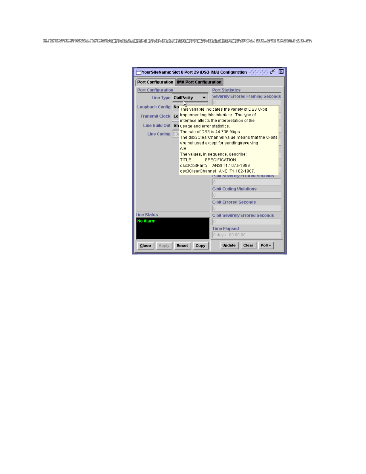
Chapter 4 Configuring Ports and Channels Using the AQueView® System
Using the Right-Click Menu
Figure 4-3. Sample of Context-Sensitive Help
(Displayed on a Port and Channel Configuration Window)
Configuring the 6Port DS1 IMA Module
You must first configure the 6-Port DS1 IMA module before you can set up
connection provisioning.
To access the port and channel configuration functions in the AQueView
system, do the following:
1. Log in to the AQueView system as a user with Administrator or
Configurator access privileges.
2. From the Device List or the Open Device window (press Ctrl+D or
Ctrl+O), open the PSAX device that contains the mo dule on which you
want to configure a port or channel. The Front Panel view and Device
Tree for that PSAX device will appear (see Figure 4-4).
PacketStar® PSAX 6-Port DS1 IMA Module User Guide, Issue1 Release7.0
4-4 255-700-166
Page 59
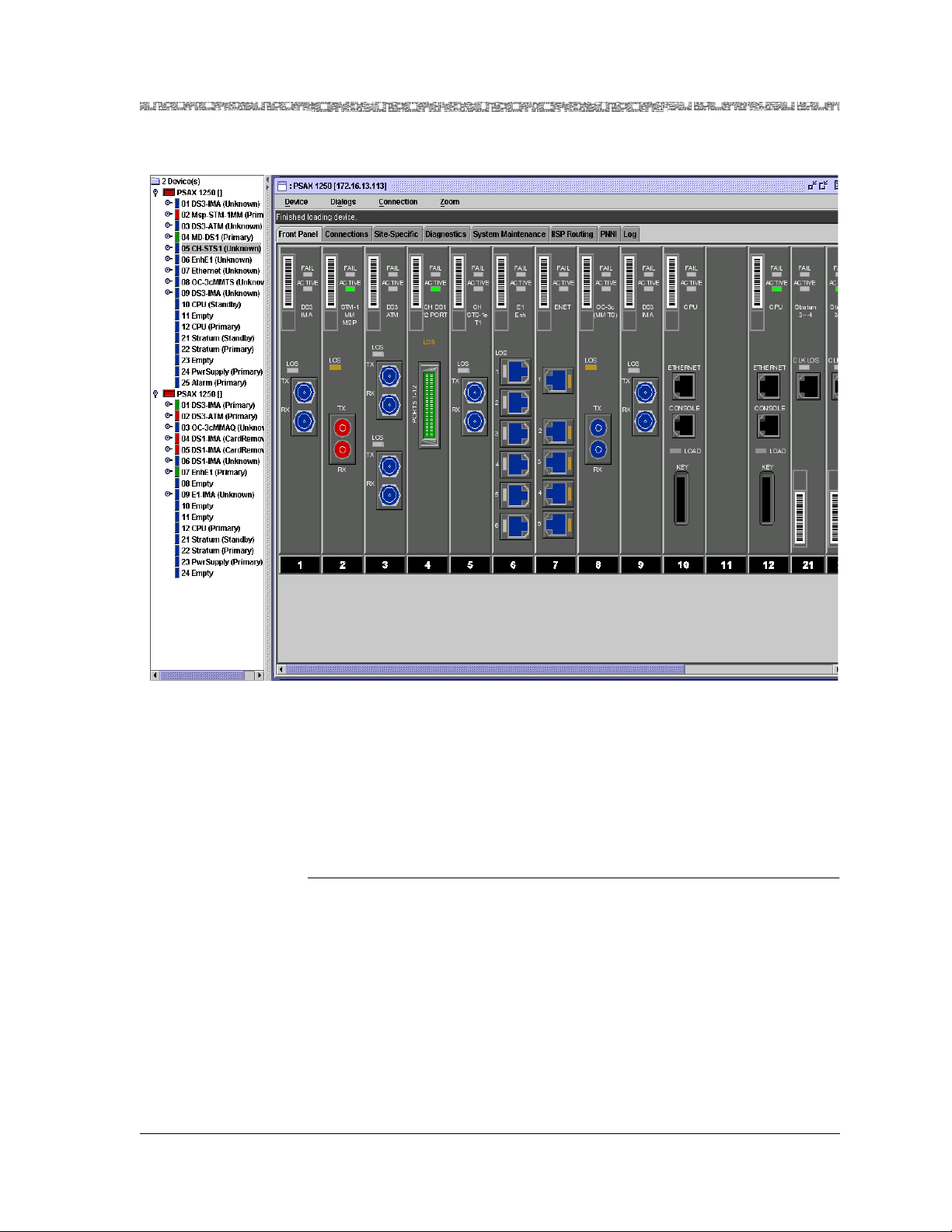
Chapter 4 Configuring Ports and Channels Using the AQueView® System
Using the Right-Click Menu
Figure 4-4. Provisioning Window (Displaying a Typical Setup)
Configuring the Module
IMA Port Configuration
PacketStar® PSAX 6-Port DS1 IMA Module User Guide, Issue1 Release7.0
255-700-166 4-5
Perform the steps in the following procedure to configure ports on the 6-Port
DS1 IMA module.
Configuring the Ports
Begin
1 Do one of the following to open the Port and Channel Configuration
window:
~ In the Front Panel, click the left button twice on the port to be
configured or displayed (see Figure 4-5).
~ In the Front Panel, double-click the right button on the port and a
menu appears. Click Configure in the menu that appears.
~ In the Device Tree, double-click the desired port symbol or identifier
with the left mouse button.
Page 60

Chapter 4 Configuring Ports and Channels Using the AQueView® System
Using the Right-Click Menu
~ In the Device Tree, select a port then click the right mouse button on
the Device Tree and a menu appears. Click Configure.
Figure 4-5. Front Panel View of the DS1 IMA Module
The DS1 IMA Port and Channel Configuration window appears (see
Figure 4-6).
Figure 4-6. DS1 IMA Port and Channel Configuration Window
The DS1 IMA Port and Channel Configuration window contains:
~ The Port Configuration page allows you to do the following:
PacketStar® PSAX 6-Port DS1 IMA Module User Guide, Issue1 Release7.0
4-6 255-700-166
Page 61

Chapter 4 Configuring Ports and Channels Using the AQueView® System
Using the Right-Click Menu
• Select and apply port settings
• View port statistics, which display line errors and coding violations
• View line status
~ The Channel Configuration page allows you to do the following:
• Select and apply an interface
• Open the Interface Configuration window to configure the
interface
Note: All interfaces must be out of service before changes can be made
to the port set tin gs; other wi se, th e Apply b utto n w ill ap pear to b e
ghosted.
Buttons The buttons in this window have the following functions:
Button Function
• Close Closes this window.
• Apply Applies the configuration field value you set.
• Reset Resets the fields to the last set of applied values.
• Copy.. Copies a port configuration to a range of ports.
• Update Updates the information in the fields.
• Clear Removes the values in the Port Statistics panel and
resets them to 0.
• P oll+ or Poll- Poll+ in itiates the contin uous upda te of stat istics. Poll-
suspends polling.
Field Descriptions 2 Select the values for the fields in this window as described in Table 4-2.
Table 4-2. Field Values for the DS1 IMA Port and Channel Configuration Window
Field Name Values Description
Line Type Default: Esf Extended Super Frame DS1 format.
(display only) D4 D4 format. Channels are assigned
sequentially.
Line Coding
(display only)
Default: B8ZS Bipolar with 8 zero substitution.
Use of a specified pattern of normal bits
and bipolar violations to replace
sequence of 8 zero bits.
Ami Alterable mark inversion. Indicates
zero code suppression.
Loopback Con-
Default: NoLoop The port is not in loopback state.
fig
PacketStar® PSAX 6-Port DS1 IMA Module User Guide, Issue1 Release7.0
255-700-166 4-7
Page 62

Chapter 4 Configuring Ports and Channels Using the AQueView® System
Using the Right-Click Menu
Table 4-2. Field Values for the DS1 IMA Port and Channel Configuration Window
Field Name Values Description
LocalLoop The signal is received from another
module in the chassis, sent through the
module circuitry, including the segmentation and reassembly (SAR) function,
and the chassis backplane to the originating module.
PayloadLoop The received signal is sent through the
framing chip on the module, but not
the SAR circuitry, and then back out to
the originating point. The data link is
regenerated.
LineLoop The received signal is sent through the
receiver and the line driver, and then
back out to the originating point.
Transmit Clock Default:
LocalTiming
Local clock source is used as the timing
source.
LoopTiming Recovered receive clock is used as the
transmit clock
Line Build Out Default:
Up To 133 Feet
Indicates the DS1 signal is designed to
be valid from 0 to 133 feet
Up To 266 Feet Indicates the DS1 signal is designed to
be valid from 134 to 266 feet
Up To 399 Feet Indicates the DS1 signal is designed to
be valid from 267 to 399 feet
Up To 533 Feet Indicates the DS1 signal is designed to
be valid from 400 to 533 feet
Up To 655 Feet Indicates the DS1 signal is designed to
be valid from 534 to 655 feet
negative7-5Db Indicates the T1 signal level range at
which the DS1 is configured is negative
7.5 dB
negative15Db Indicates the T1 signal level range at
which the DS1 is configured is negative
15 dB
negative22-5Db Indicates the T1 signal level range at
which the DS1 is configured is negative
22.5 dB
PacketStar® PSAX 6-Port DS1 IMA Module User Guide, Issue1 Release7.0
4-8 255-700-166
Page 63
Chapter 4 Configuring Ports and Channels Using the AQueView® System
Using the Right-Click Menu
Table 4-2. Field Values for the DS1 IMA Port and Channel Configuration Window
Field Name Values Description
Line Status
(display only)
Indicates the line status of the
interface: loopback, failure, received
and transmitted alarm information.
See the bit map tables for the 6-Port
DS1 IMA modu le u nd er the M IB object
lineStatus in Appendix A, "SNMP Trap
Messages" in any PacketStar™ Access
Concentrator User’s Guide.
NoAlarm
No alarm is present.
(default)
RcvFarEndLOF Far-end loss of frame.
FarEndLOF Near-end sending loss of frame
indication.
RcvAIS Far-end sending alarm indicati on signal .
AIS Near-end sending alarm indication
signal.
LossOfFrame Near-end loss of frame.
LossOfSignal Near-end loss of signal.
LoopbackState Near-end is looped.
T16AIS E1 TS16 AIS.
Rcv
Far-end sending TS16 LOMF.
FarEndLOMF
FarEndLOMF Near-end sending TS16 LOMF.
RcvTestCode Near-end detects a test code.
OtherFailure Any line status not defined here.
RmtLoopback Far-end loopback.
Interface Type
(is displayed on
the Channel
Unconfigured This interface is not configured
Ima This interface is configured as an IMA
interface.
Configuration
page)
Admin Status
(display only)
(displayed on
the Channel
Configuration
page)
Unconfigured The interface for the port is not config-
ured.
OutOfService The interface has not yet been brought
into service, or in-service interface has
been set to out of service with the Take
Out of Service button.
InService The interface has been brought into ser-
vice with the Bring Into Service button.
PacketStar® PSAX 6-Port DS1 IMA Module User Guide, Issue1 Release7.0
255-700-166 4-9
Page 64

Chapter 4 Configuring Ports and Channels Using the AQueView® System
Using the Right-Click Menu
Table 4-2. Field Values for the DS1 IMA Port and Channel Configuration Window
Field Name Values Description
Oper Status
(display only)
(displayed on
the Channel
Configuration
page)
Unconfigured This channel is not operational because
the interface is not configured.
OutOfService Two types of problems cause this status.
• A loss-of-signal condition exists due
to any one of the following:
~ The module port is not physically
connected to a cable.
~ The cable is not connected at the
other end to a device.
~ The cable is broken.
• A loss of frame or encoding exists due
to a problem with the framing or
encoding of the signal. For example,
a repeater could corrupt the signal.
InService The port is physically connected to a
cable; the cable is conducting the signal;
and the signal is being transmitted and
received correctly.
3 Click Apply.
End
Copying a Port Configuration
The Copy button on the Port and Channel Configurat ion window of each I/O
module enables you to copy a port configuration to a range of ports. To copy
a port configuration to a range of ports, perform the steps in the following
procedure from the appropriate Port and Channel Configuration window.
Copying a Port Configuration to Multiple Ports
Begin
1 On the Port Configuration page, click Copy.
The Copy Port Configuration window appears with the slot and port
of the module you selected in the Start At: and Stop At: panels (see
Figure 4-7).
PacketStar® PSAX 6-Port DS1 IMA Module User Guide, Issue1 Release7.0
4-10 255-700-166
Page 65

Chapter 4 Configuring Ports and Channels Using the AQueView® System
Using the Right-Click Menu
Figure 4-7. Sample Copy Port Configuration Window
Buttons The buttons in this window have the following functions:
Button Function
• Close Closes this window.
Channel Configuration
• Copy Copies this interface to a range of channels.
2 Select the range of slots and ports to which you wish the port
configuration to be copied.
3 To copy the interface configuration of this module, click the box beside
Copy interface configuration.
4 T o overwrite the existing interface configuration of the destination ports,
click the box beside Overwrite configured interfaces (this option is
only available if Copy interface configuration is selected).
Note: The Overwrite configured interfaces option is ghosted
until you click the box beside Copy interface configuration.
5 Click Copy.
The port configuration is copied to the range of ports you selected.
End
Perform the steps in the following procedure to configure channels on the 6Port DS1 IMA module.
Configuring the Channels
Begin
1 Click the Channel Configuration tab.
The Channel Configurat io n page appe a rs (see Figure 4-8).
PacketStar® PSAX 6-Port DS1 IMA Module User Guide, Issue1 Release7.0
255-700-166 4-11
Page 66

Chapter 4 Configuring Ports and Channels Using the AQueView® System
Using the Right-Click Menu
Figure 4-8. Channel Configuration Page
Buttons The buttons in this window have the following functions:
Button Function
• Apply to Selected Applies the configuration field value you
set .
• Configure Virtual
Channels
Displays the IMA Virtual Channel Configuration window appears (see Figure 4-9).
• Close Closes this window.
2 In the Channel Configuration page, click the Interface Type field and
select an ATM interface from the list. Click Apply to Selected.
The appropriate Interface Configuration window appears. For
information about configuring the interfaces, see Chapter 6,
"Configuring the Interfaces Using the AQueView™ System.”
3 Select the values for this interface as described in Chapter 6.
4 To update the interface configuration display, click Update.
5 To activate the interface, click Bring Into Service.
The value InService is displayed in the Administrative Status and
Operational Status fields.
6 On the Channel Configuration window, click Apply to Selected.
7 Click the right mouse button in the list in the Channel Configuration
window. A menu appears. Click Bring Into Service.
PacketStar® PSAX 6-Port DS1 IMA Module User Guide, Issue1 Release7.0
4-12 255-700-166
Page 67

Chapter 4 Configuring Ports and Channels Using the AQueView® System
Using the Right-Click Menu
8 Repeat this procedure to configure additional ports, as desired.
9 When finished configuring, click Close.
End
Viewing Port Statistics
You can view the port statistics for the 6-Port DS1 IMA module on the Port
Statistics panel of the DS1 IMA Port and Channel Configuration window
(see Figure 4-6).
Field Descriptions The field values for this window are described in Table 4-3.
Table 4-3. Data Field Descriptions of the DS1 IMA Port Statistics
Window
Field Names Description
Errored Seconds A second with at least one of the foll-
wing:
~ Path Code Violations
~ Controlled Slip events
~ A detected AIS defect
~ Presence of Bipolar Violations.
Severely
Errored Seconds
Line Coding
Violations
Time Elapsed Time elapsed since last reset.
A second with at least one of the following:
~ 320 or more Path Code Violation
Error events
~ Out of Frame defects
~ A detected AIS defect
~ A count of one-second intervals
with Framing error events, an
OOF defect, or a minimum of
1544 LCVs.
A Bipolar Violation or Excessive Zeroes
Error Event has occurred.
IMA Virtual Channels
You can set up DS1 IMA virtual channels on the 6-Port DS1 IMA module.
You can configure up to three IMA channels for each module, and each
channel can contain up to six ports.
Up to three channels can be configured on the virtual port (port 7). A group
must have at least two, and up to six of the physical ports assigned to it. For
example:
PacketStar® PSAX 6-Port DS1 IMA Module User Guide, Issue1 Release7.0
255-700-166 4-13
Page 68

Chapter 4 Configuring Ports and Channels Using the AQueView® System
Using the Right-Click Menu
~ You can assign all six of the physical ports to channel 1
~ You can assign ports 1, 3, 5 to channel 1, and ports 2, 4, and 6 to
channel 2, and so on
IMA Virtual Channel Configuration
Virtual Channel Configuration
Perform the steps in the f ollowing procedure to configure virtua l channels on
the 6-Port DS1 IMA module.
Setting the Values for the DS1 IMA Virtual Channels
Begin
1 Do one of the following to open the Port and Channel Configuration
window:
~ In the Front Panel, double-click the left mouse button on the port to be
configured or displayed.
~ In the Front Panel, double-click the right button on the port and a
menu appears. Click Configure in the menu that appears.
~ In the Device Tree, double-click the desired port symbol or identifier
with the left mouse button.
~ In the Device Tree, select a port then click the right mouse button on
the Device Tree and a menu appears. Click Configure.
2 Click the Channel Configuration tab.
3 Click Configure Virtual Channels
The IMA Virtual Channel Configuration window appears (see
Figure 4-9).
PacketStar® PSAX 6-Port DS1 IMA Module User Guide, Issue1 Release7.0
4-14 255-700-166
Page 69

Chapter 4 Configuring Ports and Channels Using the AQueView® System
Using the Right-Click Menu
Figure 4-9. IMA Virtual Channel Configuration Window
Field Descriptions 4 Select the values for the fields in this window as described in Table 4-4.
Table 4-4. Field Values for the IMA Virtual Channel Configuration Page
Field Name Values Description
Interface Type Default:
Unconfigured
The interface for this channel is not
configured.
AtmUni3_0 This interface is configured for ATM
UNI 3.0 interface.
AtmUni3_1 This interface is configured for ATM
UNI 3.1 interface.
IispUser This interface is configured for ATM
IISP User interface.
IispNetwork This interface is configured for ATM
IISP Network interface.
AtmPnni1_0 This interface is configured for ATM
PNNI 1.0 interface.
PacketStar® PSAX 6-Port DS1 IMA Module User Guide, Issue1 Release7.0
255-700-166 4-15
Page 70

Chapter 4 Configuring Ports and Channels Using the AQueView® System
Using the Right-Click Menu
Table 4-4. Field Values for the IMA Virtual Channel Configuration Page
Field Name Values Description
Port Group Range:
1–6
Displays the ports which are configured
to be in the current IMA virtual channel. If this field is blank, it shows that
no port groups are assigned to this virtual channel.
Port groups that are available are highlighted, and ports that are unavailable
are ghosted.
Minimum Tx
Links
Range: 1–6 Minimum number of transmit links
required to be active for the IMA group
to be in the Up state.
Minimum Rx
Links
Range: 1–6 Minimum number of receive links
required to be active for the IMA group
to be in the Up state.
Near-end Tx
Clock
Default: ctc Transmit clocking mode used by the
near-end IMA group. The Common
Transmit Clock (CTC) mode corresponds when the transmit clock of all
IMA links are derived from the same
source. You mus t set up the underlying
clock configuration to ensure operation
in the selected mode.
itc The Independent Transmit Clock (ITC)
mode corresponds when there is at least
one IMA link whose transmit clock is
derived from a source different than at
least one other link transmit clock. You
must set up the underlying clock configuration to ensure operation in the
selected mode.
Tx IMA ID Range: 0–255 The IMA identifier currently used by
the far-end IMA function.
Tx Frame
Length
M128 (default)
M32, M64,
M256
The frame length to be used by the IMA
group in the transmit direction. This
can be set only when the IMA group is
startup.
Link Delay Diff
(ms)
Default: 25
Range: 1–200
The maximum number of milliseconds
of delay differential among the links
that will be tolerated on this surface.
Compatibility
Mode
Default: No,
Yes
Used to indicate interoperability mode
to the I/O module in terms of reporting
the link status at the correct location in
the IMA Control Protocol (ICP)cell.
PacketStar® PSAX 6-Port DS1 IMA Module User Guide, Issue1 Release7.0
4-16 255-700-166
Page 71

Chapter 4 Configuring Ports and Channels Using the AQueView® System
Using the Right-Click Menu
Table 4-4. Field Values for the IMA Virtual Channel Configuration Page
Field Name Values Description
Alpha Value
(cells)
Default: 2
Range: 1–2
Indicates the alpha value, measured in
cells,, measured in cells, used to specify
the number of consecutive invalid ICP
cells to be detected before moving to
the IMA HUNT state. The smaller the
value, the faster the E1 and T11 IMA
will go into an error state.
Beta Value
(cells)
Default: 2
Range: 1–5
Indicates the beta value, measured in
cells, used to specify the number of consecutive errore d ICP c ells to be detect ed
before moving to the IMA HUNT state.
The smaller the value, the faster the E1
IMA will go into an error state.
Gamma Value Default: 1
Range: 1–5
Indicates the gamma value used to
specify the number of consecutive valid
ICP cells to be detected before moving
from the IMA PRESYNC state to the
IMA SYNC state.
5 Click Apply to Selected > Close.
6 Select the channel to be configured in the IMA Virtual Channel
Configuration window.
7 In the Channel Configuration page, either click the arrow in the
Interface Type field (in the middle of the window), or double-click the
channel, and select an ATM interface from the list (ATM PNNI, ATM
UNI, or ATM IISP). Click Apply to Selected.
Note: The interface canno t be configured until after the port groups
have been selected and applied to the virtual channel.
Note: You can double-click in the channel in the list to select a new
interface only when an interface is not currently selected for that
channel. If an interface is applied for a channel and you doubleclick on it in the list, the Interface Configuration window appears.
8 Click the right mouse button in the list in the Channel Configuration
window and a menu appears. Click Bring Into Service.
9 Repeat this procedure to configure additional virtual channels.
10 Click Close.
End
PacketStar® PSAX 6-Port DS1 IMA Module User Guide, Issue1 Release7.0
255-700-166 4-17
Page 72
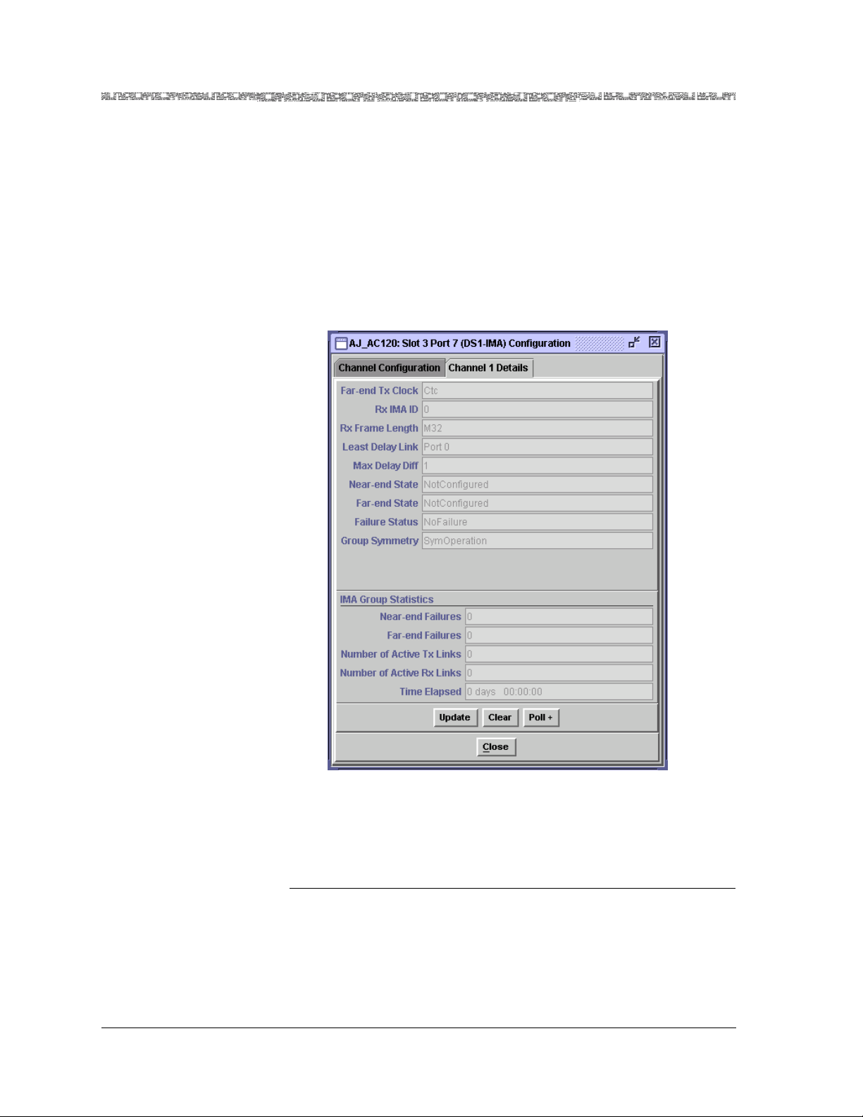
Chapter 4 Configuring Ports and Channels Using the AQueView® System
Using the Right-Click Menu
Viewing Channel Details
Perform the steps in the following procedure to view channel details for the
6-Port DS1 IMA module.
IMA Channel Details On the IMA Virtual Channel Configuration window, click the Channel 1
Details tab (or whichever channel number of which you wish to view
statistics).
The Channel 1 Details page appears (see Figure4-10).
Figure 4-10. DS1 IMA Channel Details Window
Buttons The buttons in this window have the following functions:
Button Function
• Update Updates the information in the fields.
• Clear Removes the values in the Port Statistics
panel and resets them to 0.
PacketStar® PSAX 6-Port DS1 IMA Module User Guide, Issue1 Release7.0
4-18 255-700-166
Page 73

Chapter 4 Configuring Ports and Channels Using the AQueView® System
Using the Right-Click Menu
Button Function
• Poll- or Poll+ Poll+ initiates the continuous update of
statistics. Poll- suspends polling.
• Close Closes this window.
Field Descriptions The field values for this window are described in Table 4-5.
Table 4-5. Field Values for the IMA Channel Details Page
Field Name Values Description
Far-end Tx
Clock
(display only)
Default: Ctc
Itc
Tr ans mi t c l oc ki ng mo de u se d b y the farend IMA group. There are two possible
modes: the Common Transmit Clock
(CTC) and the Independent Transmit
Clock (ITC).
The CTC mode corresponds to the case
when the transmit clock of all IMA links
are derived from the same source.
The ITC configuration corresponds to
the case where there is at least one IMA
link whose transmit clock is derived
from a source different than at least
another link transmit clock.
Rx IMA ID
(display only)
Rx Frame
Length
(display only)
Default: 0
Range: 0-255
De f a u l t : M 3 2
m64(,
m128,
The IMA ID currently in use by the far-
end IMA function.
Value of IMA frame length as received
from remote IMA function.
m256
Least Delay Link
(display only)
Default: Port 0 The interface index of the link config-
ured in the IMA group which has the
smallest link propagation delay. This
value has meaning only if at least 1 link
has been configured in the IMA group.
Max Delay Diff
(display only)
Default: 1 Maximum delay differential. The maxi-
mum number of milliseconds of delay
differential among the links that will be
tolerated on this interface.
Near-end State
(display only)
Default:
The current operational state of the
near-e nd IMA group state machine.
The group does not exist.
NotConfigured
StartUp This end is in start-up and is waiting to
receive the indications that the Far-end
is in start-up.
PacketStar® PSAX 6-Port DS1 IMA Module User Guide, Issue1 Release7.0
255-700-166 4-19
Page 74

Chapter 4 Configuring Ports and Channels Using the AQueView® System
Using the Right-Click Menu
Table 4-5. Field Values for the IMA Channel Details Page
Field Name Values Description
StartUpAck When both groups start up, they move
through this transitional state to the
Insufficient-Links state.While in this
state, indications from the near-end
that it is in start-up are ignored.
CfgAbt Configuration aborted. This state is
entered when the near-end tries to use
the following unacceptable configuration parameters.
• UnsupportedM: Unsupported value
of M
• CfgAbtInc Symmetry: Incompatible
group symmetry
• CfgAbtOther: Other reasons
Insufficient
Links
This state implies that the group has
accepted the near-end group parameters and that the near-end has also
accepted its own group parameters, and
does not have sufficient links to move
into the Operational state. This state is
excited whe “sufficient links” can be
moved into the Active state.
Blocked The group is blocked (e.g., inhibiterd by
the UM). The group can be blocked for
maintenance purposes while sufficient
links are Active in both directions.
The group is not inhibited and has sufficient links in both the Tx and Rx
directions. The IMA interface has now
the capability to receive ATM layer cells
and pass them from the IMA sublayer
to the ATM layer.
Operational The group is operational.
Far-end State
(display only)
Default:
NotConfigured
The current operational state of the
near-e nd IMA group state machine.
The group does not exist.
StartUp This end is in start-up and is waiting to
receive the indications that the nearend is in start-up.
StartUpAck When both groups start up, they move
through this transitional state to the
Insufficient-Links state.While in this
state, indications from the near-end
that it is in start-up are ignored.
PacketStar® PSAX 6-Port DS1 IMA Module User Guide, Issue1 Release7.0
4-20 255-700-166
Page 75

Chapter 4 Configuring Ports and Channels Using the AQueView® System
Using the Right-Click Menu
Table 4-5. Field Values for the IMA Channel Details Page
Field Name Values Description
CfgAbt Configuration aborted. This state is
entered when the near-end tries to use
the following unacceptable configuration parameters .
• UnsupportedM: Unsupported value
of M
• CfgAbtInc Symmetry: Incompatible
group symmetry
• CfgAbtOther: Other reasons
Insufficient
Links
This state implies that the group has
accepted the far-end group parameters
and that the far-end has also accepted
its own group parameters, and does not
have sufficient links to move into the
Operational state. This state is excited
whe “sufficient links” can be moved
into the Active state.
Blocked The group is blocked (e.g., inhibited by
the UM). The group can be blocked for
maintenance purposes while sufficient
links are Active in both directions.
The group is not inhibited and has sufficient links in both the Tx and Rx
directions. The IMA interface has now
the capability to receive ATM layer cells
and pass them from the IMA sublayer
to the ATM layer.
Operational The group is operat ional.
PacketStar® PSAX 6-Port DS1 IMA Module User Guide, Issue1 Release7.0
255-700-166 4-21
Page 76

Chapter 4 Configuring Ports and Channels Using the AQueView® System
Using the Right-Click Menu
Table 4-5. Field Values for the IMA Channel Details Page
Field Name Values Description
Failure Status
(display only)
The current failure status of the IMA
group (the reason why the group state
machine is in the down state). See the
operational state values for Near-end
State and Far-end State above.
Default:
NoFailure
StartUpNe
StartUpFe
InvalidM
ValueNe
InvalidM
ValueFe
Failed
AssymetricNe
Failed
AssymetricFe
InsuffLinksNe
InsuffLinksFe
BlockedNe
BlockedFe
OtherFailure
Group
Symmetry
(display only)
Default: SymOperation
Symmetry of the IMA group.
Symmetric operation.
AsymOperation Asymmetric operation.
AsymConfigu-
Asymmetric configuration.
ration
IMA Group Statistics panel (display only):
Near-end Fail-
ures
Default: 0 Count of near end Rx failure alarm con-
ditions has been entered on this link.
Far-end Failures
Number of
Active Tx Links
PacketStar® PSAX 6-Port DS1 IMA Module User Guide, Issue1 Release7.0
4-22 255-700-166
Default: 0 Count of far end Rx failure alarm condi-
tions has been entered on this link.
Default: 0
Range 1-32
Minimum number of transmit links
required to be Active for the IMA group
to be in the Up state.
Page 77

Chapter 4 Configuring Ports and Channels Using the AQueView® System
Using the Right-Click Menu
Table 4-5. Field Values for the IMA Channel Details Page
Field Name Values Description
Number of
Active Rx Links
Default: 0
Range 1–32
Minimum number of receive links
required to be Active for the IMA group
to be in the Up state.
Time Elapsed Default: 0 days
00:00:00
Time elapsed, in days, hours, minutes,
and seconds, since last reset.
PacketStar® PSAX 6-Port DS1 IMA Module User Guide, Issue1 Release7.0
255-700-166 4-23
Page 78

Chapter 4 Configuring Ports and Channels Using the AQueView® System
Using the Right-Click Menu
PacketStar® PSAX 6-Port DS1 IMA Module User Guide, Issue1 Release7.0
4-24 255-700-166
Page 79

5 Configuring the Interfaces Using
Overview of This Chapter
This chapter provides instructions for configuring the 6-Port DS1 IMA
module for the ATM IMA interface. Before you can set interface
configuration values, you must select an interface type value other than
Unconfigured in the Interface Type field on the DS1 IMA Port and Channel
Configuration window.
Note: Ports 1-6 of the 6-Port DS1 IMA module can be configured for
native DS1 ATM interfaces and for the ATM IMA interface.
However, when you configure a group (channel), you may
configure it for one of the following interfaces: ATM IISP User,
ATM IISP Network, ATM UNI 3.0, ATM UNI 3.1, ATM UNI 4.0 or
ATM PNNI 1.0.
For a matrix of modules and supporting interface types, see the Interface
Types by I/O Module Types Table in the Reference Tables appendix of your
PacketStar
®
PSAX User Guide.
the Console
Errors in Applying Interfaces to Ports
An error can occur when you apply an interface to a port or channel. If an
error condition occurs, the Multiservice Media Gateway sends an SNMP trap
that usually appears in the console Trap Log Display (accessible from the
Console Interface Main Menu window). The list below includes the most
common interface errors that cause the PSAX system to display a message.
(See the appendix, “SNMP Trap Messages,” for more information about the
SNMP traps related to interface errors).
• Entering values into fields that are outside of the configurable range of
values
• Attempting to configure an interface for a port or channel that has
already been configured
• Attempting to configure an interface that is already in service (must be
out of service to be configured or change field values)
• Entering field values that are not recognized by the PSAX system
software
PacketStar® PSAX 6-Port DS1 IMA Module User Guide, Issue1 Release7.0
255-700-166 5-1
Page 80

Chapter 5 Configuring the Interfaces Using the Console
AT M IMA Inte rface
ATM IMA Interface
This section provides instructions for configuring an I/O module for the ATM
Inverse Multiplexing over ATM (IMA) interface. You may configure the
following I/O modules for the ATM IMA interface:
• 6-Port DS1 IMA module
• 1-Port DS3 IMA module
• 6-Port E1 IMA module
Automatic Use of IMA Links
In an IMA group, if one link is broken, the group can be configured to
automatically use the other links. For example, if an IMA group has three
DS1 links and one of the links fails, although the throughput will drop from
4.5 Mbps to 3.0 Mbps, the IMA group continues to work. If the slowest link
fails, there will be some cell loss on CBR connections as the other links speed
up their cell rate to eliminate excess delay, due to their buffering of cells.
IMA Configuration Considerations
Note: If your PSAX unit will be interoperating with a device that has
implemented ATM Forum IMA ATM Specification Version 1.0
such that its equipment incorrectly reports link states to the farend of an IMA connection, you must configure IMA groups with
the compatibility mode turned on. This also causes the PSAX unit to
correctly report link states and interoperate with your ATM
Forum IMA ATM Specification Version 1.0 equipment.
The following is a list of operations considerations for the IMA interface:
• Once an IMA group has been deleted, its status is displayed as
"Insufficient-Links."
• Links may not be added or removed from a group that is configured. You
must delete any existing interfaces applied to the group before adding or
removing links.
• Operational Status refers to IMA group status, which can be viewed in
the port and channel configuration window.
~ You can restart an IMA group by taking it administratively out of
service and then bringing it back into service.
~ In order to change any group configuration parameters, the group
must be completely unconfigured.
~ There may be difficulties if the IMA group is configured for symetric
operation but has asymetric link delays. For example, one end may
consider links A, B, and C to have problems, while the other end
considers D, E, and F to have problems.
~ Four configurable transmit frame lengths are provided: 32, 64, 128,
256 cells. One ICP (IMA communication protocol) cell is sent over
each link once per IMA frame. If you select a larger frame length,
PacketStar® PSAX 6-Port DS1 IMA Module User Guide, Issue1 Release7.0
5-2 255-700-166
Page 81

there will be less overhead. If you select a smaller frame length, the
IMA group has better response in communications with the far end,
resulting in faster error detection and recovery. The IMA specification
only requires equipment to support a frame length of 128. If a frame
length other than 128 is configured and the far-end is connected to
equipment that doesn’t support it, the far-end group enters the configabort state.
~ The IMA identifier (ID) is an 8-bit (0-255) identifier for this IMA
group. There is no significance to any particular values of IMA IDs.
Since the IMA ID is used to identify a group to the far-end, pick a
unique value instead of leaving it as the default of 0.
Accessing the ATM IMA Interface
If you selected the value AtmIma as the interface type, the ATM IMA
Interface Configuration window (see Figure 5-1) is displayed.
Chapter 5 Configuring the Interfaces Using the Console
ATM IMA Interface
Figure 5-1. ATM IMA Interface Configuration Window
Commands The commands in this window have the following functions:
PacketStar® PSAX 6-Port DS1 IMA Module User Guide, Issue1 Release7.0
255-700-166 5-3
Page 82

Chapter 5 Configuring the Interfaces Using the Console
AT M IMA Inte rface
Command Function
• Update Display Refreshes the values in the Link States and the Defects
fields
• Bring Interface Into
Service (is displayed
when the [Admin Sta-
tus] field is OutOfService)
Brings an out-of-ser vice configured interface int o service.
The value InService is displayed in the [Admin Status]
field.
An asterisk is displayed beside all the configured channels
indicating that they are in service.
Note: You must first configure the interface before you
can use this command.
• Take Interface Out of
Service (is displayed
when the [Admin
Takes the in-service configured interface out of service.
The displayed asterisk is removed from all configured
channels indicating that they are out of service.
Status] field is InSer-
vice)
Note: Y o u must use th is command first be fore using the
Delete Interface and Return command.
• Delete Interface and
Return
Deletes an out-of-service interface and redisplays the
ATM IMA Configuration window.
Note: You must first take interface out of service (using
the Take Interface Out of Service command) before you
can use this command.
• Continuous Update Updates the values in the fields every second.
• Reset Statistics Removes the values in the Interface Statistics fields and
resets them to 0.
• Go Back to Port
Configuration
Redisplays the Port and Channel Configuration window
for the module you are configuring.
ATM IMA Values Descriptions of the values for the fields on this window are described in
Table 5-1.
Table 5-1. Field Values for the ATM IMA Interface Configuration Window
Field Name Values Description
[Oper Status]
(display only)
[Admin Status]
(display only)
In service Indicates that the interface is operational.
Out of service Indicates that the interface is not operational.
InService Indicates that the interface is in service.
OutOfService Indicates that the interface is not in service.
PacketStar® PSAX 6-Port DS1 IMA Module User Guide, Issue1 Release7.0
5-4 255-700-166
Page 83

Chapter 5 Configuring the Interfaces Using the Console
Table 5-1. Field Values for the ATM IMA Interface Configuration Window
Field Name Values Description
Link States panel
(display only): [Nearend Tx], [Far-end Tx],
[Near-end Rx], [Farend Rx]
Defects panel (display
only):
[Near-end Rx], [Farend Rx]
NotInGroup Interface is not assigned to a group.
UnusableNo-
Does not work; non-specific reason.
Reason
Unusable Fault Local failure status of a link belonging to an
IMA group (not currently supported.)
The PSAX device does not generate this con-
dition, but may report such a condition generated by the far end of an IMA connection.
Unusable
Misconnected
An IMA link is not corrected to the proper
end. (The PSAX device does not currently
generate this condition, but the PSAX device
reports this condition to the user if the far-end
reports it to the PSAX device.)
For example, when an IMA group is established, the links immediately discover which
device they are connecting to on the far end.
If cables are then removed and plugged back
in differently , then the equipment may signify
that it is misconnected.
Unusable Inhibited
This is an administrative mechanism for taking an IMA link out of service. When in this
state, it is unknown whether there are any
physical problems with the link.
Unusable Failed Check the defect value displayed.
Usable There are no local reasons why this link is not
active. The only thing preventing it from
being active is the far-end state (for example,
a transmitter cannot be active and send real
data until the far-end receiver is ready to
accept that data).
Active Interface in use.
NoDefect No link defects.
Link failure Physical failure/loss of signal.
LIF Persistent los s of IMA frame.
LODS Link out of delay synchronization.
Interface Statistics panel (display only)
[IMA Violations]
Count of errored, invalid or missing cells dur-
ing non-SES-IMA condition.
[OIF
Anomalies]
[Near-end Tx Failures]
Count of OIF anomalies during non-SES-IMA
conditions.
Count of near end Tx failure alar m conditions
has been entered on this link.
ATM IMA Interface
PacketStar® PSAX 6-Port DS1 IMA Module User Guide, Issue1 Release7.0
255-700-166 5-5
Page 84

Chapter 5 Configuring the Interfaces Using the Console
Interim Interswitch Signaling Protocol (IISP) Interface
Table 5-1. Field Values for the ATM IMA Interface Configuration Window
Field Name Values Description
[Near-end Rx Failures]
[Far-end Tx Failures]
[Far-end Rx Failures]
[Tx Stuffs]
[Rx Stuffs]
[Time Elapsed]
Count of near end Rx failure alarm conditions
has been entered on this link.
Count of far end transmit failure alarm conditions has been entered on this link.
Count of far end receive failure alarm conditions has been entered on this link.
Count of stuff events inserted in the transmit
direction on this link.
Count of stuff events received in receive
direction on this link.
Time elapsed since last reset.
Activating the IMA Interface
To activate the interface on the ATM IMA Interface Configurat ion Window,
select the Bring Interface Into Service command and press Enter.
Interim Interswitch Signaling Protocol (IISP) Interface
Interim Interswitch Signaling Protocol (IISP), formerly known as PNNI Phase
0, was introduced as an interim standard, pending completion of the PNNI
Phase 1. Building on ATM UNI 3.0 and ATM UNI 3.1, it uses static routing
tables established by the network administrator to route connections around
link failures.
The IISP interface requires the default range of values 0–255 for the virtual
path identifier (VPI) and 32–255 for the virtual channel identifier (VCI) to
accept and establish calls. This value is set on the ATM IISP Interface
Configuration window.
Each connection using the IISP interface is configurable as either the user
side or the network side.
Optimizing SVC Call Performance
The service-specific connection-oriented protocol (SSCOP) field is set on
these interface configuration windows: ATM IISP network or IISP user, ATM
UNI 3.0 or UNI 3.1, or ATM PNNI 1.0.
Note: These settings are suggested for connecting to a Multiservice
Media Gateway from a remote site only. The Multiservice Media
Gateway configures these settings internally in its own ATM
switch.
When there are unacknowledged protocol data units (PDUs), the MaxPD
field on the remote end peer (such as the NavisCore
PacketStar® PSAX 6-Port DS1 IMA Module User Guide, Issue1 Release7.0
5-6 255-700-166
™
CBX 500™) shows the
Page 85

maximum number of SSCOP transmitted since the last PSAX polling of the
peer. To optimize call performance, the SSCOP Rx Window Size field of the
local ATM interface should be less than the maximum value displayed in the
MaxPD credit window at the remote end of the ATM interface. Otherwise,
the rate at which switched calls can be set and released may be degraded.
On the ATM IISP Interface Configuration window, the maximum credit
window (the SSCOP Rx Window Size field) is configurable for a value up to
32 for all ATM interfaces on the Multiservice Media Gateway. The interfaces
of the ATM switches that are connected to an Multiservice Media Gateway
should be configured to the same values. This results in 100% call
completion at a call setup rate of 60 calls per second using even distribution.
If these values are not configured in this way, calls will be set up at a rate of
less than 60 calls per second.
Note: Vari ous SSCOP paramete r setti ngs deter mine th e maximum c redit
window. As a result, you may not be able to directly use these
settings.
Configuring the ATM IISP Interface
Chapter 5 Configuring the Interfaces Using the Console
Interim Interswitch Signaling Protocol (IISP) Interface
When you select the value IispUser or IispNetwork as the interface ty pe on a
module port and channel configuration window associated with one of the
modules listed at the beginning of this chapter, the ATM IISP Interface
Configuration window (see Figure 5-2) appears.
Figure 5-2. ATM IISP Interface Configuration Window
PacketStar® PSAX 6-Port DS1 IMA Module User Guide, Issue1 Release7.0
255-700-166 5-7
Page 86

Chapter 5 Configuring the Interfaces Using the Console
Interim Interswitch Signaling Protocol (IISP) Interface
Commands The commands in this window have the following functions:
Command Function
• Apply Interface Config-
Applies the configuration field value you set.
uration
• Reset Interface Display•Resets the fields to the last set of applied values.
• Bring Interface Into
Service (displays when
the [Admin Status]
field is OutOfService)
• Take Interface Out of
Service (displays when
the [Admin Status]
field is InService)
Brings an out-of-service configured interface to in-service status.
The value InService is displayed in the [Admin Status]field.
You must first configure the interface before you can use this
command.
T akes an in-service configured interface to out-of-service status.
The value OutOfService is displayed in the [Admin Status]
field.
Note: You must use this command first before using the
Delete Interface and Return command.
• Delete Interface and
Return
→
Deletes an out-of-service interface and redi splays the Port and
Channel Configuration window for the module you are configuring.
Note: You must first take interface out of service (using the
Take Interface Out of Service command) before you can use
this command.
• Continuous Update Continuously updates the information in the Interface Statistics
fields every second. Select this command and press Enter to turn
the continuous updating on and off as needed.
• Reset Statistics Removes the values in the Interface Statistics fields and resets
them to 0.
• Go Back to Port Configuration
→
Redisplays the port and channel configuration window of the
module you are configuring.
To set values for the ATM IISP interface, perform the steps in the following
procedure.
Setting the Values for the ATM IISP Interface
Begin
1 Select the values for the fields on this window from the values given in
Table 5-2.
Field Descriptions Table5-2 lists the field values for the ATM IISP Interface Configuration
window.
PacketStar® PSAX 6-Port DS1 IMA Module User Guide, Issue1 Release7.0
5-8 255-700-166
Page 87

Chapter 5 Configuring the Interfaces Using the Console
Interim Interswitch Signaling Protocol (IISP) Interface
Table 5-2. Field Values for the ATM IISP Interface Configuration Window
Field Name Values Description
[Oper Status]
(display only)
Indicates whether the interface is operational according to
the Administrative Status below.
InService The interface is operational.
OutOfService The interface is not operational because some condition is
preventing the port from being fully operational, such as a
loss of signal to the port.
[Admin Status]
(display only)
Indicates the Administra tive S tat us of the interf a ces ; or what
the interface(s) are configured as.
InService The interface is in service.
OutOfService The interface is not in service.
Over
Subscription
Default: 10
Range: 1–100
The risk factor for this function. This factor indicates the fac-
tor of oversubscription allowed for this interface.
Note: For the ma ximum and minimum VPI/ VCI values below, always e nter or change th e
maximum value before the minimum value.
Min SVC VPI Default: 0
Range: 0–255
Max SVC VPI Default: 0
Range: 0–255
Min SVC VCI Default: 32
The minimum VPI value in which signaling can occur.
Note: Disable ATM signaling field if you want to use VPI 0.
The maximum VPI in which signaling can occur.
Note: Disable ATM signaling field if you want to use VPI 0.
The minimum VCI in which signaling can occur.
Range: 0–65535
Max SVC VCI Default: 255
The maximum VCI in which signaling can occur.
Range: 0–65535
ATM Signaling Default:
Disabled
SVCs cannot be created on this interface.
Note: VPI 0 is not available for use.
Enabled SVCs can be created on this interface.
Note: VPI 0 is available for use.
PacketStar® PSAX 6-Port DS1 IMA Module User Guide, Issue1 Release7.0
255-700-166 5-9
Page 88

Chapter 5 Configuring the Interfaces Using the Console
Interim Interswitch Signaling Protocol (IISP) Interface
Table 5-2. Field Values for the ATM IISP Interface Configuration Window
Field Name Values Description
UPC Suppo rt Usage parameter control (policing) determines if traffic con-
trol is performing to negotiated PCR, SCR, or MBS. This feature is supported on these modules:
• OC-12c/STM-4c MM/SM 1+1 APS/MSP
• OC-3c 1+1 APS SM/MM
• STM-1 1+1 MSP SM/MM
• Channelized DS3-to-DS0
• High Density E1
• Medium Density DS1
Default:
Disabled
UPC Support is disabled.
Note: If UPC Support is disabled, traffic policing cannot be
supported on any VC.
Enabled UPC Support is enabled, providing traffic policing support for
all VCs.
UBR Load
Balancing
Default:
Disabled
Balance UBR traffic load among parallel links.
UBR Load Balancing is disabled.
Note: Virtual interfaces do not support UBR Load
Balancing.
Enabled UBR Load Balancing is enabled.
SSCOP Rx Wnd
Size
The service-specific connection-oriented protocol (SSCOP)
layer. This window shows the total number of packets that
must be acknowledged by the receiving side before more
packets are sent from the transmitting side.
Default: 32
Range: 8–256
Traffic Shaping
On the receiving side, values must be equal to or greater than
the values for the transmit side for fastest transmission rates.
An input cell selection algorithm (leaky bucket) that smooths
bursts of input traffic.
Available on th ese modules only :
STM-1 Multi-Mode and Single-Mode,
OC-3c Multi-Mode and Single-Mode
Default:
Disables the feature.
Disabled
Enabled Note: Enables the feature.
This feature must be enabled if using rate shaping prior to
egress from an ATM trunk port on the OC-3c APS or the
STM-1 MSP modules
Interface Statistics Panel (display only)
[Valid Cells
Rcvd]
[Errored Cells
Rcvd]
Number of valid cells received since the statistics were last
reset.
Number of errored cells received since the statistics were last
reset.
PacketStar® PSAX 6-Port DS1 IMA Module User Guide, Issue1 Release7.0
5-10 255-700-166
Page 89

Chapter 5 Configuring the Interfaces Using the Console
ATM User-Network Interface 3.0, 3.1, and 4.0
Table 5-2. Field Values for the ATM IISP Interface Configuration Window
Field Name Values Description
[Mismatched
Cells Rcvd]
[Valid Cells
Sent]
[Null Cells Sent]
[Time Elapsed]
[Ingress Avail
BW] (cps)
(display only)
[Egress Avail
BW] (cps)
(display only)
Default: 0 This represents the total ingress and egress bandwidth avail-
Default: 0 This represents the total ingress and egress bandwidth avail-
Number of mismatched cells received since the statistics were
last reset.
Number of valid cells sent since the statistics were last reset.
Number of null cells sent since the statistics were last reset.
Time elasped since counter began running since the statistics
were last reset.
able for virtual interfaces. 0 will change to 353207 after
Apply has been selected. As each new virtual interface is
created, the amount of available bandwidth as indicated in
this field will decrease. The value of this field ranges from
0–353207 after being brought in service.
able for virtual interfaces. 0 will change to 353207 after
Apply has been selected. As each new virtual interface is
created, the amount of available bandwidth as indicated in
this field will decrease. The value of this field ranges from
0–353207 after being brought in service.
2 To apply the interface configuration values, select the Apply Interface
Configuration command and press Enter.
3 T o activate the inter face after you have ap plied the configuration values ,
select the Bring Interface Into Service command and press Enter.
Note: The interface must have in-service status so that the PVCs and
SVCs you will set up to use this interface will work.
End
ATM User-Network Interface 3.0, 3.1, and 4.0
Configuring the Interface
When you select the value AtmUni3-0, AtmUni3-1, or AtmUni4-0 as the
interface type on a module port and channel configuration window
associated with one of the modules listed on the ATM UNI Interface
Configuration window is displayed (see Figure 5-3).
PacketStar® PSAX 6-Port DS1 IMA Module User Guide, Issue1 Release7.0
255-700-166 5-11
Page 90
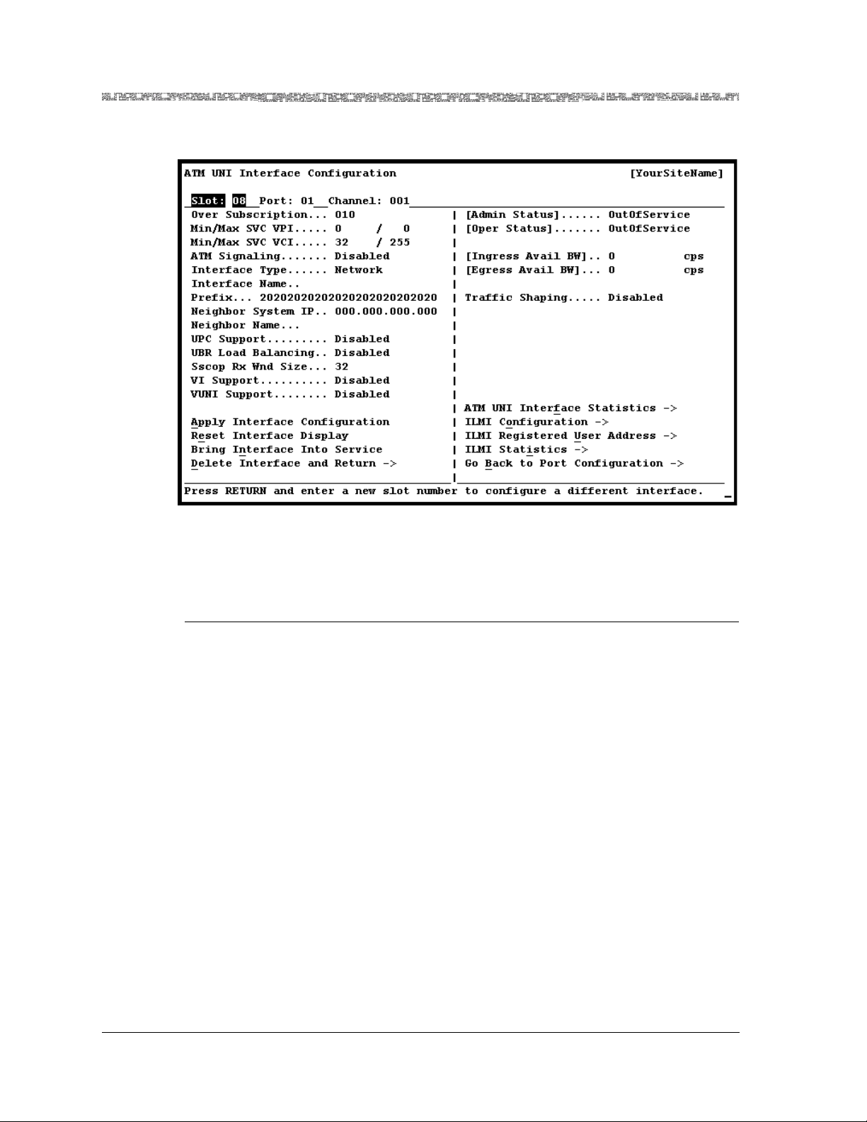
Chapter 5 Configuring the Interfaces Using the Console
ATM User-Network Interface 3.0, 3.1, and 4.0
Figure 5-3. ATM UNI Interface Configuration Window
Commands The commands in this window have the following functions:
Command Function
• Apply Interface Config-
Applies the configuration field value you set.
uration
• Reset Interface Display Resets the fields to the last set of applied values.
• Br i n g Int e rfa c e In t o
Service (displays when
the [Admin Status]
field is OutOfService)
Brings an out-of-service configured interface to in-service
status. The value InService is displayed in the [Admin Sta-
tus] field.
Note: Y ou mus t first configure the interface b efore you
can use this command.
• Take Interface Out o f
Service (displays when
the [Admin Status]
field is InService)
Takes an in-service configured interface to out-of-service
status. The value OutOfService is displayed in the [Admin
Status] field.
Note: You must use this command first before using
the Delete Interface and Return command.
• Delete Interface and
Return
Deletes an out-of-service interface and redisplays the Port
and Channel Configuration window for the module you
are configuring.
Note: You must first take the interface out of service
(by selecting the Take Interface Out of Service
command) before you can use this command.
PacketStar® PSAX 6-Port DS1 IMA Module User Guide, Issue1 Release7.0
5-12 255-700-166
Page 91

Chapter 5 Configuring the Interfaces Using the Console
ATM User-Network Interface 3.0, 3.1, and 4.0
Command Function
• ATM UNI Interface
Displays the ATM UNI Interface Statistics window.
Statistics
• ILMI Configuration Displays the ATM UNI ILMI Configuration window.
• ILMI Registered User
Displays the ILMI Registered User Address Table.
Address
• ILMI Statistics Displays the ILMI Statistics window
• Go Back to Port Configuration
Redisplays the port and channel configuration window of
the module you are configuring.
Field Descriptions To set values for the ATM UNI interface, perform the steps in the following
procedure.
Setting the Values for the ATM UNI Interface
Begin
1 Select the values for the fields on this window from the values given in
Table 5-3.
Table 5-3. Field Descriptions for the ATM UNI Interface Configuration Window
Field Name Values Description
Over Subscription Default: 10
Range: 1–100
The risk factor for this function. This factor indicates
the level of oversubscription allowed by the system.
Note: For the maximum and minimum VPI and VC I values below, always enter or change
the maximum value before the minimum value.
Min/Max SVC VPI
The minimum and maximum VPI values that you
can assign to an SVC on this interface.
Note: Disable the ATM signaling field if you want
to use VPI 0.
Default: 0
Range: 0–255
Min/Max SVC VCI Min: 32
(default)
Max: 255
(default)
Enter the maximum value afte r the slash and then
enter the minimum value before the slash.
The minimum and maximum VCI values that you
can assign to an SVC on this interface. Enter the
maximum value after the slash and then enter the
minimum value before the slash.
Range: 0–65535
ATM Signaling Default:
Disabled
SVCs cannot be created on this interface.
Note: VPI 0 is not available for use.
Enabled SVCs can be created on this interface.
Note: VPI 0 is available for use.
PacketStar® PSAX 6-Port DS1 IMA Module User Guide, Issue1 Release7.0
255-700-166 5-13
Page 92

Chapter 5 Configuring the Interfaces Using the Console
ATM User-Network Interface 3.0, 3.1, and 4.0
Table 5-3. Field Descriptions for the ATM UNI Interface Configuration Window
Field Name Values Description
Interface Type Default:
Network
Indicates that the NNI f ormat for the cell headers will
be used.
Note: When you select this value, the Prefix field
is displayed below the Interface Name field.
User Indicates that the UNI format fo r the cell heade rs will
be used.
Note: When you select this value, the User Add
field is displayed below the Interface Name field.
Interface Name (Maximum
string of 20
characters)
A textual name of this interface. This interface must
be uniquely named on this system to distinguish parallel links with a neighboring system. If this interface does not have a textual name, the value of this
object is a zero-length string.
Prefix Default:
2020202020202
0202020202020
Range: 13-byte
(18-hexadecimal digit begin-
Network prefix address displays when the value Net-
work is selected in the Interface Type field. This
address is used only for address registration procedure of ILMI. This field represents the first 13 bytes
of the 20-byte NSAP address. The last 7 bytes are the
user part of this address (User Add field).
ning with 39, 45
or 47)
User Add Default:
2020202020202
User address di splays when the val ue User is selecte d
in the Interfac e Type field.
0202020202020
Range: 13-byte
(18-hexadecimal digit beginning with 39, 45
or 47)
Neighbor
System IP
Default:
000.000.000.00
0 (IP address)
This field is used for auto-discovery protocol. Displays the IP address of the attached device for an
ILMI-enabled interface, or the user-configured IP
address for an ILMI-disabled interface.
For an ILMI-enabled interface, any user-configured
value overrides ILMI discovered values.
Enter the IP address of the PSAX chassis (or other
device) to which the physical connection is made
using this interface.
Neighbor Name Format: 20
alphanumeric
characters
This field is used for identifying network topology.
Enter a descriptive name up to 20 characters in
length for the PSAX chassis (or other device) to
which the physical connection is made using this
interface.
PacketStar® PSAX 6-Port DS1 IMA Module User Guide, Issue1 Release7.0
5-14 255-700-166
Page 93
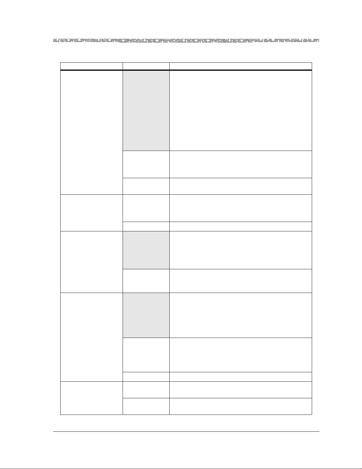
Chapter 5 Configuring the Interfaces Using the Console
ATM User-Network Interface 3.0, 3.1, and 4.0
Table 5-3. Field Descriptions for the ATM UNI Interface Configuration Window
Field Name Values Description
UPC Support Usage parameter control (policing) determines if
traffic control is performing to negotiated PCR, SCR,
or MBS. This feature is supported on these modules:
• OC-12c/STM-4c MM/SM 1+1 APS/MSP
• OC-3c 1+1 APS SM/MM
• STM-1 1+1 MSP SM/MM
• Cha nn eli zed DS3- to-DS 0
• High Density E1
• Medium Density DS1
Default:
Disabled
UPC support is disabled.
Note: If UPC Support is disabled, traffic policing
cannot be supported on any VC.
Enabled UPC support is enabled, providing traffic policing
support for all VCs.
UBR Load Balancing
Default:
Disabled
Unspecified bit rate (UBR) load balancing is disabled.
Note: The virtual interface does not support UBR
load balancing.
Enabled UBR load balancing is enabled.
SSCOP Rx Wnd Size
The service-specific connection-oriented protocol
(SSCOP) layer. This window shows the total number
of packets that must be acknowledged by the receiving side before more packets are sent from the trans-
mitting side.
Default: 32
Range: 8–256
VI Support
On the receiving side, the window size for this value
must be equal to or greater than the values for the
transmitting side for fastest transmission rates.
Virtual interfaces connect to a module’s physical
ports and allow virtu al channe ls (VCs) to be assigne d
to virtual trunks, each with its own priority queue.
This option is available only for these modules:
OC3-c APS,
STM-1 MSP.
Enabled Feature is enabled, providing bandwidth allocation
restrictions.
Note: In order to configure a virtual interface, you
must select Enabled.
Disabled VI support is disabled.
[Admin Status] (display only)
InService Indicates that no conditions are preventing the port
from being fully operational.
OutOfService Indicates that some condition is preventing the por t
from being configured with an interface.
PacketStar® PSAX 6-Port DS1 IMA Module User Guide, Issue1 Release7.0
255-700-166 5-15
Page 94
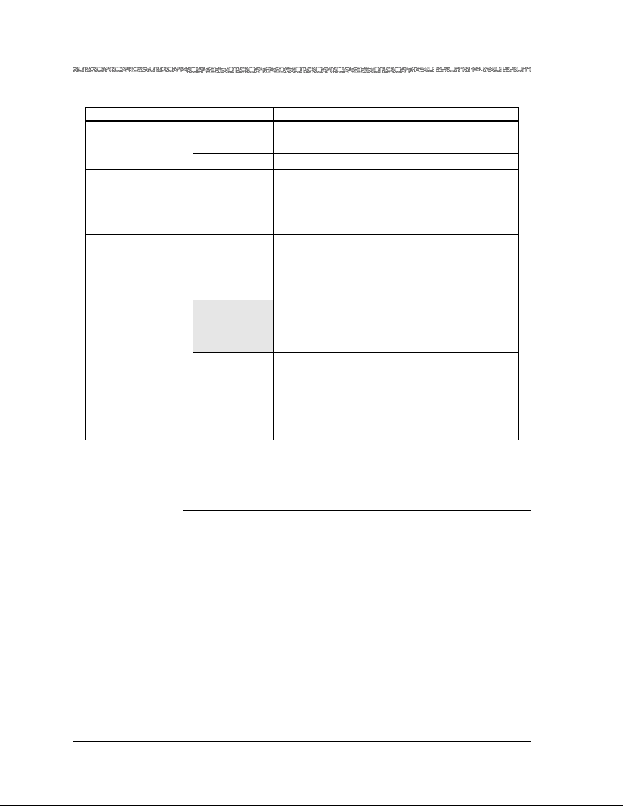
Chapter 5 Configuring the Interfaces Using the Console
ATM User-Network Interface 3.0, 3.1, and 4.0
Table 5-3. Field Descriptions for the ATM UNI Interface Configuration Window
Field Name Values Description
[Oper Status] (display only)
Unconfigured Indicates that this interface has not been configured.
InService Indicates that the interface is operational.
OutOfService Indicates that the interface is not operational.
[Ingress Avail BW]
(cps)
(display only)
Default: 0 This represents the total ingress bandwidth available
for virtual interfaces. The value 0 changes to 353207
after you select the Apply command. As each new
virtual interface is created, the amount of available
bandwidth as indicated in this field decreases.
[Egress Avail BW]
(cps)
(display only)
Default: 0 This represents the total egress bandwidth available
for virtual interfaces. The value 0 changes to 353207
after you select the Apply command. As each new
virtual interface is created, the amount of available
bandwidth as indicated in this field decreases.
Traffic Shaping
An input cell selection algorithm (leaky bucket) that
smooths bursts of input traffic. Available on these
modules: STM-1 Multi-Mode and Single-Mode, OC3c Multi-Mode and Single-Mode.
Default:
Disables the feature.
Disabled
Enabled Enables the feature.
2 To apply the interface configuration values, select the Apply Interface
Configuration command and press Enter.
End
Viewing ATM UNI Interface Statistics
On the ATM UNI Interface Configuration window (see Figure 5-3), select the
ATM UNI Interface Statistics command and press Enter.
The ATM UNI Interface Statistics window is displayed (see Figure 5-4).
Note: Field must be set to enabled if using rate
shaping on the OC-3c APS or the STM-1 MSP
modules prior to egress from an ATM trunk port.
PacketStar® PSAX 6-Port DS1 IMA Module User Guide, Issue1 Release7.0
5-16 255-700-166
Page 95
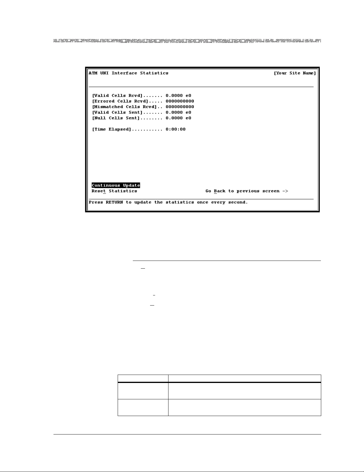
Chapter 5 Configuring the Interfaces Using the Console
ATM User-Network Interface 3.0, 3.1, and 4.0
Figure 5-4. ATM UNI Interface Statistics Window
Commands The commands on this window have the following functions:
Command Function
•Continuous Update Continuously updates all fields once every
second.
•Reset
• Go B
Statistics Resets statistics counters for this interface.
ack to previous
screen –>
Returns to the ATM UNI Interface
Configuration window.
Field Descriptions The fields on this window are described in Table 5-4.
Table 5-4. Field Values for the ATM UNI Interface StatisticsWindow
Field Name Description
[Valid Cells Rcvd] Number of valid cells received into interface side A dur-
ing the amount of time shown in Time Elapsed field.
[Errored Cells
Rcvd]
Number of errored cells received into interface side A
during the amount of time shown in Time Elapsed field.
PacketStar® PSAX 6-Port DS1 IMA Module User Guide, Issue1 Release7.0
255-700-166 5-17
Page 96

Chapter 5 Configuring the Interfaces Using the Console
ATM User-Network Interface 3.0, 3.1, and 4.0
Table 5-4. Field Values for the ATM UNI Interface StatisticsWindow
Field Name Description
[Mismatched
Cells Rcvd]
Number of mismatched cells received into interface side
A during the amount of time shown in Time Elapsed
field.
[Valid Cells Sent] Number of valid cells transmitted out of interface side B
during the amount of time shown in Time Ela p se d field.
[Null Cells Sent] Number of null cells transmitted out of interface side B
during the amount of time shown inTime Elapsed field.
NOTE: This parameter is not supported in the
OC-12c/STM-4c SM/MM 1+1 APS/MSP modules.
[Time Elapsed] Time elapsed since the last reset in h:mm:ss (hour:
minute:seconds) format.
Configuring ATM UNI ILMI
For more information on ILMI, see Chapter 3 “System Features,” of the
appropriate PacketStar
®
Multiservice Media Gateway User Guide.
When you select the ILMI Configuration command on the ATM UNI
Interface Configuration window (see Figure 5-3 on page 5-12), the ATM UNI
ILMI Configuration window is displayed (see Figure 5-5).
Figure 5-5. ATM UNI ILMI Configuration Window
Commands The commands in this window have the following functions:
PacketStar® PSAX 6-Port DS1 IMA Module User Guide, Issue1 Release7.0
5-18 255-700-166
Page 97

Chapter 5 Configuring the Interfaces Using the Console
Command Function
• Apply ILMI Configura-
tion
ATM User-Network Interface 3.0, 3.1, and 4.0
Applies the configuration field values you
set.
• Go Back to Interface
Screen
Redisplays the ATM UNI Interface
Configuration window.
To set values for ILMI configuration, perform the steps in the following
procedure.
Setting the Values for the ATM UNI ILMI Configuration Window
Begin
Field Descriptions 1 Select the values for the fields on this window from the values given in
Table 5-5.
Table 5-5. Field Values for the ATM UNI ILMI Configuration Window
Field Nam e Values Description
[ILMI Oper Status]
InService Indicates that ILMI connectivity is operational.
OutOfService Indicates that ILMI connectivity is not operational.
(display only)
ILMI Protocol Default:
Disabled
If you select Disabled, the other fields in this window
will not take effect.
Enabled Enables ILMI.
Address
Registration
Default:
Disabled
Address registration can be enabled only if the ILMI
Protocol field is enabled.
Enabled Enables address registration.
Connectivity
Procedure
Default:
Disabled
ILMI Connectivity Procedure is disabled. You must
select Enabled if you want to also enable the Attach-
ment Point Detection and Secure Link fields.
Enabled ILMI Connectivity Procedure is enabled.
Attachment
Point Detection
Default:
Disabled
Enabled
Attachment Point Change Detection can be enabled
only if Connectivity Procedure and ILMI Protocol
fields are enabled.
Enabled A query will be sent every 5 seconds to detect a
change in the address. A response indicates that the
user id and address information are the same. However, if there is a change in the address, all calls will
be cleared.
PacketStar® PSAX 6-Port DS1 IMA Module User Guide, Issue1 Release7.0
255-700-166 5-19
Page 98

Chapter 5 Configuring the Interfaces Using the Console
ATM User-Network Interface 3.0, 3.1, and 4.0
Table 5-5. Field Values for the ATM UNI ILMI Configuration Window
Field Nam e Values Description
Secure Link Default:
Disabled
ILMI Secure Link Procedure is disabled. It can be
enabled only if Connectivity Procedure and Attach-
ment Point Detection fields are enabled.
Enabled ILMI Secure Link Procedure is enabled. If you do not
receive a response, all calls are cleared, and you will
be disconnected.
[Auto Configuration]
(display only)
Default:
Disabled
The ability to automatically configure VPI and VCI is
disabled.
Enabled Automatically configures the VPI and VCI.
Auto configuration can be enabled only if the ILMI
Protocol field is enabled.
[TimerT]
(display only)
Default: 5
Range: Varies
Timer T in seconds. Used to poll when link is operational.
The value in this field in displayed as a 32-bit integer,
and any number may appear.
[TimerS]
(display only)
Default: 1
Range: Varies
Timer S in seconds. Used to poll when link is not
operational.
The value in this field in displayed as a 32-bit integer,
and any number may appear.
[RetryK]
(display only)
Default: 4
Range: Varies
Retry K in seconds. In dicates the numb er of ti meouts
before the link becomes non-operational.
The value in this field in displayed as a 32-bit integer,
and any number may appear.
[ILMI VPI]
(display only)
Default: 0
This value does
VPI for the ILMI protocol channel in which VPI will
run.
not change.
[ILMI VCI]
(display only)
Default: 16
This value does
VCI for the ILMI protocol channel in which VCI will
run.
not change.
2 To apply the interface configuration values, select the Apply ILMI
Configuration command and press Enter.
3 To go back to the ATM UNI Interface Configuration window, select the
Go Back to Interface Screen command and press Enter.
4 T o activate the inter face after you have ap plied the configuration values ,
select the Bring Interface Into Service command and press Enter.
Displaying Registered Addresses
PacketStar® PSAX 6-Port DS1 IMA Module User Guide, Issue1 Release7.0
5-20 255-700-166
5 Select the ILMI Registered User Address Table command and press
Enter.
Page 99

Chapter 5 Configuring the Interfaces Using the Console
ATM User-Network Interface 3.0, 3.1, and 4.0
The ILMI Registered User Address Table window is displayed (see
Figure 5-6).
Figure 5-6. ILMI Registered User Address Table Window
Commands The commands in this window have the following functions:
Command Function
• Find.. Atm Addr: . . • Finds the user’s ATM address.
• Go Back to Interface
Screen
→
• Redisplays the ATM UNI Inte rface C onfigu ration window.
The NSAP Address (Hex) column displays the user’s registered
addresses. The Org Scope column displays the scope of the registered
addresses. If the scope is not set by the user, it will default to global (a
value of 15).
6 To go back to the ATM UNI Interface Configuration window, select the
Go Back to Interface Screen command and press Enter.
Viewing ILMI Statistics
To view ILMI configuration statistics, do the following:
7 Select the ILMI Statistics command and press Enter .
The ILMI Statistics window is displayed (see Figure 5-7).
PacketStar® PSAX 6-Port DS1 IMA Module User Guide, Issue1 Release7.0
255-700-166 5-21
Page 100

Chapter 5 Configuring the Interfaces Using the Console
ATM User-Network Interface 3.0, 3.1, and 4.0
Figure 5-7. ILMI Statistics Window
Commands The commands in this window have the following functions:
Command Function
• Continuous Update Continuously updates the information in the
fields every second. Select this command and
press Enter to turn the continuous updating on
and off as needed.
• Reset Statistics Resets the statistics counters for the ILMI Statistics window.
• Go Back to Interface
Screen
→
Redisplays the ATM UNI Interface Configuration
window.
Field Descriptions The fields in this window are described in Table 5-6.
Table 5-6. Field Descriptions for the ILMI Statistics Window
Field Name Description
[Link Resets]
Number of times connectivity went down and then up again.
(display only)
[AttachPt Changed]
Number of times attachment p oi nt change was detected.
(display only)
PacketStar® PSAX 6-Port DS1 IMA Module User Guide, Issue1 Release7.0
5-22 255-700-166
 Loading...