

Page 1

PacketStar® PSAX
8-Port Voice 2-Wire Station Module
User Guide
for the PacketStar® PSAX Multiservice Media Gateways
Issue 1, September 2002
System Software Release 8.0.0
®
AQueView
EMS Software Release 6.0
Doc. No.: 255-700-261
Page 2

Copyright © 2002 by Lucent Technologies. All rights reserved.
For trademark, regulatory compliance, and related legal information,
see the "Legal Notices, Safety, and Regulatory Information" section.
Page 3

Legal Notices, Safety, and Regulatory
Copyright
Trademarks
Infomation
Copyright © 2002 by Lucent Technologies. All rights reserved.
This material is protected by the copyright laws of the United States and
other countries. It may not be reproduced, distributed, or altered in any fashion by any entity (either internal or external to Lucent Technologies), except
in accordance with applicab le agreements , contracts o r licensing, wi thout the
express written consent of the originating organization and the business
management owner of the material.
This document was prepared by the Information Design and Development
T eam of Lucent Technologies, PacketStar PSAX product s. Of fices ar e locat ed in
Landover, Maryland, USA.
PacketStar, AQueView, Lucent, Lucent Technologies, and the Lucent Technolo-
gies logo are register ed tradema rks of Lucent Technologies in the USA. Other
product and brand names mentioned in this guide are trademarks or registered trademarks of their respective owners.
Notices
The information in this document is for informational use only, is subject to
change without notice, and should not be construed as a commitment by
Lucent Technologies, Inc. This document is without warranty of any kind,
either expressed or implied. Lucent Technologies, Inc. assumes no responsibility for any errors, inaccuracies, or omissions. Neither is any liability
assumed for damages resulting from the use of the information or instructions contained herein. Lucent Technologies, Inc. is not responsible for any
damage or loss to your data or equipment resulting either directly or indirectly from use of this document.
Warranty Information
Software and Hardware Limited Warranties
Lucent Technologies provides a 90-day limited software warranty, and a oneyear limited hardware warranty on this product. Refer to the Software License
and Limited Warranty Agreement and the Lucent Technologies InterNetworking Systems Global Warranty that accompanied your package for more information.
PacketStar® 8-Port Voice 2-Wire Station Module User Guide, Issue 1 Release 8.0.0
255-700-261 iii
Page 4

Legal Notices, Safety, and Regulatory Infomation
Safety Warnings and Information
Warr anty Warnings
!
CAUTION:
Modifying or tampering with PSAX chassis components may void your
warranty. Any modification to this equipment not expressly authorized
by Lucent Technologies may void your granted authority to operate such
equipment.
!
CAUTION:
When inserting modules into the chassis, slide them gently, not forcefully. Excessive force may cause the modules to be seated improperly in
the chassis, and result in possible damage to the module or the chassis.
Install or remove modules one at a time. Doing this aids in preventing
the PSAX system from indicating any erroneous failure messages, and
allows the PSAX system to reinitialize and display the accurate configuration of the module that is inserted.
!
CAUTION:
Shipping the chassis with removable I/O, server, or CPU modules
installed may cause damage to the chassis and the modules. Damage to
any of the components in the system resulting from shipping the chassis
with removable modules installed will void your warranty. Only Lucentauthorized personnel should ship the PSAX chassis with a module
installed.
Safety Warnings and Information
When installing and operating the 8-Port Voice 2-Wire Station module, follow the safety guidelines provided in the printed PacketStar
Guidelines, which accompanies this product, to help prevent serious personal
injury and damage to the 8-Port Voice 2-Wire Station module. Please read all
warnings and instructions supplied before beginning installation or configuration of this module. In additio n to the general sa fety inf ormation pro vided,
you should also refer to the text in the PacketStar PSAX user and installation
guides for other important safety information and procedures.
Regulatory Standards Compliance
®
PSAX Safety
Safety and Electromagnetic Compatibility (EMC)
The following PacketStar PSAX systems are compliant with applicable safety
and EMC standards when configured with the 8-Port
Voice 2-Wire Stationmodule (model 20N30):
PacketStar® 8-Port Voice 2-Wire Station Module User Guide, Issue 1 Release 8.0.0
iv 255-700-261
Page 5

Legal Notices, Safety, and Regulatory Infomation
Regulatory Standard s Compli an c e
• PSAX 1000 system
• PSAX 1250 system
• PSAX 2300 system
• PSAX 4500 system
Please refer to the appropriate PacketStar PSAX Multiservice Media Gateway
user guide or installation guide for additional information.
PacketStar® 8-Port Voice 2-Wire Station Module User Guide, Issue 1 Release 8.0.0
255-700-261 v
Page 6

Legal Notices, Safety, and Regulatory Infomation
Regulatory Standards Compliance
PacketStar® 8-Port Voice 2-Wire Station Module User Guide, Issue 1 Release 8.0.0
vi 255-700-261
Page 7

Table of Contents
Legal Notices, Safety, and Regulatory Infomation . . . . . . . . . . . . . . . . . . iii
Copyright . . . . . . . . . . . . . . . . . . . . . . . . . . . . . . . . . . . . . . . . . . . . . . . . . . . . . . . . . . . . . iii
Trademarks . . . . . . . . . . . . . . . . . . . . . . . . . . . . . . . . . . . . . . . . . . . . . . . . . . . . . . . . . . . . iii
Notices . . . . . . . . . . . . . . . . . . . . . . . . . . . . . . . . . . . . . . . . . . . . . . . . . . . . . . . . . . . . . . . iii
Warranty Information . . . . . . . . . . . . . . . . . . . . . . . . . . . . . . . . . . . . . . . . . . . . . . . . . . . . . iii
Software and Hardware Limited Warranties . . . . . . . . . . . . . . . . . . . . . . . . . . . . . . . . . iii
Warranty Warnings . . . . . . . . . . . . . . . . . . . . . . . . . . . . . . . . . . . . . . . . . . . . . . . . . . . iv
Safety Warnings and Information . . . . . . . . . . . . . . . . . . . . . . . . . . . . . . . . . . . . . . . . . . . . iv
Regulatory Standards Compliance . . . . . . . . . . . . . . . . . . . . . . . . . . . . . . . . . . . . . . . . . . . iv
Safety and Electromagnetic Compatibility (EMC) . . . . . . . . . . . . . . . . . . . . . . . . . . . . . iv
List of Figures . . . . . . . . . . . . . . . . . . . . . . . . . . . . . . . . . . . . . . . . . . . . . . . xi
List of Tables . . . . . . . . . . . . . . . . . . . . . . . . . . . . . . . . . . . . . . . . . . . . . . . xiii
1 Getting Started. . . . . . . . . . . . . . . . . . . . . . . . . . . . . . . . . . . . . . . . . . . . . . 1-1
Purpose of This Guide . . . . . . . . . . . . . . . . . . . . . . . . . . . . . . . . . . . . . . . . . . . . . . . . . . . .1-1
Audience for This Guide . . . . . . . . . . . . . . . . . . . . . . . . . . . . . . . . . . . . . . . . . . . . . . . . . .1-1
What You Should Know . . . . . . . . . . . . . . . . . . . . . . . . . . . . . . . . . . . . . . . . . . . . . . . . . .1-1
Related Reading . . . . . . . . . . . . . . . . . . . . . . . . . . . . . . . . . . . . . . . . . . . . . . . . . . . . . . . .1-2
Lucent Technologies Information Products . . . . . . . . . . . . . . . . . . . . . . . . . . . . . . . . .1-2
Product Information Library . . . . . . . . . . . . . . . . . . . . . . . . . . . . . . . . . . . . . . . . .1-2
Other Publications . . . . . . . . . . . . . . . . . . . . . . . . . . . . . . . . . . . . . . . . . . . . . . . . . . .1-2
About Lucent Technologies . . . . . . . . . . . . . . . . . . . . . . . . . . . . . . . . . . . . . . . . . . . . . . . .1-2
About the PacketStar PSAX Product Family . . . . . . . . . . . . . . . . . . . . . . . . . . . . . . . . . . . .1-2
PSAX 1000 Multiservice Media Gateway. . . . . . . . . . . . . . . . . . . . . . . . . . . . . . . . . . .1-2
PSAX 1250 Multiservice Media Gateway. . . . . . . . . . . . . . . . . . . . . . . . . . . . . . . . . . .1-3
PSAX 2300 Multiservice Media Gateway. . . . . . . . . . . . . . . . . . . . . . . . . . . . . . . . . . .1-3
PSAX 4500 Multiservice Media Gateway. . . . . . . . . . . . . . . . . . . . . . . . . . . . . . . . . . .1-4
Document Conventions . . . . . . . . . . . . . . . . . . . . . . . . . . . . . . . . . . . . . . . . . . . . . . . . . .1-4
Text Types Used in This Document. . . . . . . . . . . . . . . . . . . . . . . . . . . . . . . . . . . . . . . .1-4
Icons and Symbols . . . . . . . . . . . . . . . . . . . . . . . . . . . . . . . . . . . . . . . . . . . . . . . . . . .1-5
Use of Command Description Tables. . . . . . . . . . . . . . . . . . . . . . . . . . . . . . . . . . . . . .1-5
Use of Field Description Tables . . . . . . . . . . . . . . . . . . . . . . . . . . . . . . . . . . . . . . . . . .1-6
General Document Navigational Guidelines. . . . . . . . . . . . . . . . . . . . . . . . . . . . . . . . . . . .1-6
Selecting Options, Fields and Commands Using the Console Interface . . . . . . . . . . . .1-6
Help Information. . . . . . . . . . . . . . . . . . . . . . . . . . . . . . . . . . . . . . . . . . . . . . . . . . . . . . . .1-8
Technical Support . . . . . . . . . . . . . . . . . . . . . . . . . . . . . . . . . . . . . . . . . . . . . . . . . . . . . . .1-9
iii
xi
xiii
1-1
.1-1
.1-1
.1-1
.1-2
.1-2
.1-2
.1-2
.1-2
.1-2
.1-2
.1-3
.1-3
.1-4
.1-4
.1-4
.1-5
.1-5
.1-6
.1-6
.1-6
.1-8
.1-9
iii
iii
iii
iii
iii
iv
iv
iv
iv
PacketStar® 8-Port Voice 2-Wire Station Module User Guide, Issue 1 Release 8.0.0
255-700-261 vii
Page 8

Table of Contents
Before You Begin. . . . . . . . . . . . . . . . . . . . . . . . . . . . . . . . . . . . . . . . . . . . . . . . . . . . . . . 1-9
Comments on This Guide . . . . . . . . . . . . . . . . . . . . . . . . . . . . . . . . . . . . . . . . . . . . . . . . 1-9
2 Module Description. . . . . . . . . . . . . . . . . . . . . . . . . . . . . . . . . . . . . . . . . . .2-1
Overview of the 8-Port Voice 2-Wire Station Module. . . . . . . . . . . . . . . . . . . . . . . . . . . . 2-1
Software Features . . . . . . . . . . . . . . . . . . . . . . . . . . . . . . . . . . . . . . . . . . . . . . . . . . . . . . 2-2
Module Placement Requirements. . . . . . . . . . . . . . . . . . . . . . . . . . . . . . . . . . . . . . . . . . . 2-2
Hardware Features. . . . . . . . . . . . . . . . . . . . . . . . . . . . . . . . . . . . . . . . . . . . . . . . . . . . . . 2-2
General Hardware Features. . . . . . . . . . . . . . . . . . . . . . . . . . . . . . . . . . . . . . . . . . . . 2-2
Chassis Speed, Power Consumption, and Memory Allocation . . . . . . . . . . . . . . . . . . 2-3
LED Indicators. . . . . . . . . . . . . . . . . . . . . . . . . . . . . . . . . . . . . . . . . . . . . . . . . . . . . . 2-3
3 Configuring Ports and Channels Using the Console Interface. . . . . . . . .3-1
Overview of This Chapter . . . . . . . . . . . . . . . . . . . . . . . . . . . . . . . . . . . . . . . . . . . . . . . . 3-1
Before You Begin. . . . . . . . . . . . . . . . . . . . . . . . . . . . . . . . . . . . . . . . . . . . . . . . . . . . . . . 3-1
Obtaining General Module Data and Accessing Ports and Channels. . . . . . . . . . . . . . . . . 3-1
Configuring the Module . . . . . . . . . . . . . . . . . . . . . . . . . . . . . . . . . . . . . . . . . . . . . . . . . 3-7
Saving the Equipment Configuration and Logging Off. . . . . . . . . . . . . . . . . . . . . . . . . . 3-15
4 Configuring Interfaces Using the Console Interface. . . . . . . . . . . . . . . . .4-1
Before You Begin. . . . . . . . . . . . . . . . . . . . . . . . . . . . . . . . . . . . . . . . . . . . . . . . . . . . . . . 4-1
Errors When Applying Interfaces to Ports. . . . . . . . . . . . . . . . . . . . . . . . . . . . . . . . . . . . . 4-1
The Circuit Emulation Interface . . . . . . . . . . . . . . . . . . . . . . . . . . . . . . . . . . . . . . . . . . . . 4-1
Managing Circuit Emulation Interfaces . . . . . . . . . . . . . . . . . . . . . . . . . . . . . . . . . . . 4-1
Configuring a Circuit Emulation Interface . . . . . . . . . . . . . . . . . . . . . . . . . . . . . . . . . 4-2
Bringing a Circuit Emulation Interface Into Service. . . . . . . . . . . . . . . . . . . . . . . . . . . 4-4
Viewing the Parameters of a Specific Circuit Emulation Interface. . . . . . . . . . . . . . . . 4-5
Viewing the Circuit Emulation Module Port Statistics. . . . . . . . . . . . . . . . . . . . . . . . . 4-5
Taking a Circuit Emulation Interface Out of Service . . . . . . . . . . . . . . . . . . . . . . . . . . 4-6
Deleting a Circuit Emulation Interface . . . . . . . . . . . . . . . . . . . . . . . . . . . . . . . . . . . . 4-6
Modifying a Circuit Emulation Interface. . . . . . . . . . . . . . . . . . . . . . . . . . . . . . . . . . . 4-7
Provisioning Connections . . . . . . . . . . . . . . . . . . . . . . . . . . . . . . . . . . . . . . . . . . . . . 4-8
1-9
1-9
2-1
2-1
2-2
2-2
2-2
2-2
2-3
2-3
3-1
3-1
3-1
3-1
3-7
3-15
4-1
4-1
4-1
4-1
4-1
4-2
4-4
4-5
4-5
4-6
4-6
4-7
4-8
5 Configuring Ports and Channels Using the AQueView
Overview of This Chapter . . . . . . . . . . . . . . . . . . . . . . . . . . . . . . . . . . . . . . . . . . . . . . . . 5-1
Using the Right-Click Menu. . . . . . . . . . . . . . . . . . . . . . . . . . . . . . . . . . . . . . . . . . . . . . . 5-1
Accessing Configuration Options. . . . . . . . . . . . . . . . . . . . . . . . . . . . . . . . . . . . . . . . . . . 5-2
Configuring the Module . . . . . . . . . . . . . . . . . . . . . . . . . . . . . . . . . . . . . . . . . . . . . . . . . 5-3
Configuring Channels. . . . . . . . . . . . . . . . . . . . . . . . . . . . . . . . . . . . . . . . . . . . . . . . 5-8
Applying an Interface to a Channel. . . . . . . . . . . . . . . . . . . . . . . . . . . . . . . . . . . 5-8
PacketStar® 8-Port Voice 2-Wire Station Module User Guide, Issue 1 Release 8.0.0
viii 255-700-261
®
EMS . . . . . . . . .5-1
5-1
5-1
5-1
5-2
5-3
5-8
5-8
Page 9

Table of Contents
6 Configuring Interfaces Using the AQueView
Before You Begin . . . . . . . . . . . . . . . . . . . . . . . . . . . . . . . . . . . . . . . . . . . . . . . . . . . . . . .6-1
Errors Applying Interfaces to Ports. . . . . . . . . . . . . . . . . . . . . . . . . . . . . . . . . . . . . . . . . . .6-1
The Circuit Emulation Interface . . . . . . . . . . . . . . . . . . . . . . . . . . . . . . . . . . . . . . . . . . . . .6-1
Configuring Circuit Emulation Interface Values . . . . . . . . . . . . . . . . . . . . . . . . . . . . . .6-5
Provisioning Connections . . . . . . . . . . . . . . . . . . . . . . . . . . . . . . . . . . . . . . . . . . . . . . . . .6-6
A Wiring Configurations. . . . . . . . . . . . . . . . . . . . . . . . . . . . . . . . . . . . . . . . A-1
Purpose of this Appendix . . . . . . . . . . . . . . . . . . . . . . . . . . . . . . . . . . . . . . . . . . . . . . . . A-1
B Reference Information. . . . . . . . . . . . . . . . . . . . . . . . . . . . . . . . . . . . . . . . B-1
Overview of This Appendix . . . . . . . . . . . . . . . . . . . . . . . . . . . . . . . . . . . . . . . . . . . . . . . .B-1
Call Tone Detection Settings . . . . . . . . . . . . . . . . . . . . . . . . . . . . . . . . . . . . . . . . . . . . . . .B-1
DSP Channel Reduction Availability Due to Fax Relay Mode. . . . . . . . . . . . . . . . . . . . . . . .B-1
Industry Compliance Specifications . . . . . . . . . . . . . . . . . . . . . . . . . . . . . . . . . . . . . . . . . .B-2
Interface Type by Connection Type Table . . . . . . . . . . . . . . . . . . . . . . . . . . . . . . . . . . . . .B-12
Interface Type by Input/Output Module Type Table. . . . . . . . . . . . . . . . . . . . . . . . . . . . . .B-13
Module Alarm Status Table . . . . . . . . . . . . . . . . . . . . . . . . . . . . . . . . . . . . . . . . . . . . . . .B-18
8-Port Voice 2-Wire Station Module Line Status Table . . . . . . . . . . . . . . . . . . . . . . . . . . .B-19
Quality of Service (QOS) Tables . . . . . . . . . . . . . . . . . . . . . . . . . . . . . . . . . . . . . . . . . . . .B-19
®
EMS. . . . . . . . . . . . . . . . 6-1
6-1
.6-1
.6-1
.6-1
.6-5
.6-6
A-1
A-1
B-1
.B-1
.B-1
.B-1
.B-2
.B-12
.B-13
.B-18
.B-19
.B-19
Glossary . . . . . . . . . . . . . . . . . . . . . . . . . . . . . . . . . . . . . . . . . . . . . Glossary-1
PacketStar® 8-Port Voice 2-Wire Station Module User Guide, Issue 1 Release 8.0.0
255-700-261 ix
Page 10

Table of Contents
PacketStar® 8-Port Voice 2-Wire Station Module User Guide, Issue 1 Release 8.0.0
x 255-700-261
Page 11

List of Figures
1-1 Main Menu Help Window . . . . . . . . . . . . . . . . . . . . . . . . . . . . . . . . . . . . . . . . . . . . . . . . . . .1-8
2-1 Voice 2-Wire Station Module . . . . . . . . . . . . . . . . . . . . . . . . . . . . . . . . . . . . . . . . . . . . . . . . .2-1
3-1 Sample Equipment Configuration Window on a PSAX 1000 System (Page 1) . . . . . . . . . . . . .3-2
3-2 Sample Equipment Configuration Window on a PSAX 1250 System (Page 1) . . . . . . . . . . . . .3-3
3-3 Sample Equipment Configuration Window on a PSAX 2300 or PSAX 4500 System (Page 1) . .3-3
3-4 Sample Equipment Configuration Window on a PSAX 1000, PSAX 2300, or PSAX 4500 System
(Page 2) . . . . . . . . . . . . . . . . . . . . . . . . . . . . . . . . . . . . . . . . . . . . . . . . . . . . . . . . . . . . . . . . .3-4
3-5 Sample Equipment Configuration Window on a PSAX 1250 System (Page 2) . . . . . . . . . . . . .3-4
3-6 Console Interface Main Menu (Equipment Configuration Selected) . . . . . . . . . . . . . . . . . . . . .3-8
3-7 Equipment Configuration Window (As Displayed on the PSAX 1000, PSAX 1250, PSAX 2300, and
PSAX 4500 Console) . . . . . . . . . . . . . . . . . . . . . . . . . . . . . . . . . . . . . . . . . . . . . . . . . . . . . . . .3-9
3-8 Two Wire Station Configuration Window . . . . . . . . . . . . . . . . . . . . . . . . . . . . . . . . . . . . . . .3-10
3-9 Two Wire Station Port and Channel Configuration window . . . . . . . . . . . . . . . . . . . . . . . . .3-12
4-1 Circuit Emulation Interface Configuration Window . . . . . . . . . . . . . . . . . . . . . . . . . . . . . . . . .4-3
5-1 Sample Port Configuration (Displaying Right-Click Menu) . . . . . . . . . . . . . . . . . . . . . . . . . . . .5-1
5-2 Sample Channel Configuration (Displaying Right-Click Menu) . . . . . . . . . . . . . . . . . . . . . . . . .5-1
5-3 Device Tree and Device Window (Displaying a Typical Setup) . . . . . . . . . . . . . . . . . . . . . . . . .5-3
5-4 Front Panel View of the Voice 2-Wire Station Module . . . . . . . . . . . . . . . . . . . . . . . . . . . . . . .5-4
5-5 2-Wire Station Port and Channel Configuration Window . . . . . . . . . . . . . . . . . . . . . . . . . . . .5-5
5-6 Channel Configuration Page . . . . . . . . . . . . . . . . . . . . . . . . . . . . . . . . . . . . . . . . . . . . . . . . . .5-8
6-1 Circuit Emulation Interface Configuration Window . . . . . . . . . . . . . . . . . . . . . . . . . . . . . . . . .6-2
.1-8
.2-1
.3-2
.3-3
.3-3
.3-4
.3-4
.3-8
.3-9
.3-10
.3-12
.4-3
.5-1
.5-1
.5-3
.5-4
.5-5
.5-8
.6-2
PacketStar® 8-Port Voice 2-Wire Station Module User Guide, Issue 1 Release 8.0.0
255-700-261 xi
Page 12

List of Figures
PacketStar® 8-Port Voice 2-Wire Station Module User Guide, Issue 1 Release 8.0.0
xii255-700-261
Page 13

List of Tables
1-1 Text Conventions . . . . . . . . . . . . . . . . . . . . . . . . . . . . . . . . . . . . . . . . . . . . . . . . . . . . . . . . . .1-5
1-2 Command Description Table Example . . . . . . . . . . . . . . . . . . . . . . . . . . . . . . . . . . . . . . . . . . .1-6
1-3 Field Description Table Example . . . . . . . . . . . . . . . . . . . . . . . . . . . . . . . . . . . . . . . . . . . . . . .1-6
1-4 System Responses to Selecting Options, Fields, or Commands . . . . . . . . . . . . . . . . . . . . . . . .1-7
1-5 Shortcut Keys for Navigating Console Interface Windows . . . . . . . . . . . . . . . . . . . . . . . . . . . .1-7
2-1 Physical Hardware Specifications . . . . . . . . . . . . . . . . . . . . . . . . . . . . . . . . . . . . . . . . . . . . . . .2-3
2-2 Performance and Power Specifications for the 8-Port Voice 2-Wire Station Module . . . . . . . .2-3
2-3 LED Indicators for the 8-Port Voice 2-Wire Station Module . . . . . . . . . . . . . . . . . . . . . . . . . .2-4
3-1 Commands for the Equipment Configuration Window . . . . . . . . . . . . . . . . . . . . . . . . . . . . . .3-5
3-2 Field Descriptions for the Equipment Configuration Window . . . . . . . . . . . . . . . . . . . . . . . . .3-5
3-3 Alarm Status Descriptions for Modules on the Equipment Configuration Window . . . . . . . . .3-7
3-4 Commands for the Two Wire Station Configuration Window . . . . . . . . . . . . . . . . . . . . . . . .3-10
3-5 Commands for the Two Wire Station Port and Channel Configuration Window . . . . . . . . . .3-12
3-6 Field Descriptions for the Two Wire Station Port and Channel Configuration Window . . . . .3-13
4-1 Commands for the Circuit Emulation Interface Window . . . . . . . . . . . . . . . . . . . . . . . . . . . . .4-3
4-2 Field Descriptions for the Circuit Emulation Interface Configuration Window . . . . . . . . . . . . .4-4
5-1 Field Descriptions for the Two Wire Station Port and Channel Configuration Window . . . . . .5-6
6-1 Field Descriptions for the Circuit Emulation Interface Configuration Window . . . . . . . . . . . . .6-5
B-1 DSP Tone Detection Modes and Associated Processing Performed . . . . . . . . . . . . . . . . . . . . .B-1
B-2 Channel Reduction Availabilit y Caused by Fax Relay Connections vs. Voice
Processing Connections on a DSP2C Module . . . . . . . . . . . . . . . . . . . . . . . . . . . . . . . . . . . .B-2
B-3 Industry Compliance Specifications . . . . . . . . . . . . . . . . . . . . . . . . . . . . . . . . . . . . . . . . . . . . .B-3
B-4 Connection Type by Interface Type Table . . . . . . . . . . . . . . . . . . . . . . . . . . . . . . . . . . . . . . .B-12
B-5 Interface Types by I/O Module Types . . . . . . . . . . . . . . . . . . . . . . . . . . . . . . . . . . . . . . . . . . .B-14
B-6 Alarm Status Descriptions for Modules on the Equipment Configuration Window . . . . . . . .B-18
B-7 Voice 2 Wire Office and Voice 2 Wire Station Line Status Codes . . . . . . . . . . . . . . . . . . . . . .B-19
B-8 PSAX System-Supported Quality of Service Classes . . . . . . . . . . . . . . . . . . . . . . . . . . . . . . . .B-20
B-9 Class of Service Descriptions . . . . . . . . . . . . . . . . . . . . . . . . . . . . . . . . . . . . . . . . . . . . . . . . . B -20
B-10 Cell Loss and Cell Delay Characteristics of ATM Service Classes . . . . . . . . . . . . . . . . . . . . . . .B-21
B-11 Mapping ATM Service Classes to PSAX System Priority Levels . . . . . . . . . . . . . . . . . . . . . . . .B-21
.1-5
.1-6
.1-6
.1-7
.1-7
.2-3
.2-3
.2-4
.3-5
.3-5
.3-7
.3-10
.3-12
.3-13
.4-3
.4-4
.5-6
.6-5
.B-1
.B-2
.B-3
.B-12
.B-14
.B-18
.B-19
.B-20
.B-20
.B-21
.B-21
PacketStar® 8-Port Voice 2-Wire Station Module User Guide, Issue 1 Release 8.0.0
255-700-261 xiii
Page 14

List of Tables
PacketStar® 8-Port Voice 2-Wire Station Module User Guide, Issue 1 Release 8.0.0
xiv255-700-261
Page 15

Purpose of This Guide
The PacketStar® 8-Port V oi ce 2- W ire Sta tion M odule provides a description of the
8-Port Voice 2-Wire Station module. It also provides the following information:
• PacketStar I/O module configuration overview
• Using the PSAX system to configure ports and channels
• Using the PSAX system to configure interfaces
For information on provisioning connections, see the PacketStar
Provisioning Connectio ns User Guide for PacketStar
ways.
Note: If you are using this module for the first time, you should read
through this guide in its entirety before beginning the configuration process. The chapters in this guide are arranged in the logical
order of normal configuration and should be performed in that
order to achieve optimum performance of the module(s).
1 Getting Started
®
®
PSAX Multiservice Media Gate-
PSAX Sys tem
Audience for This Guide
The information in this guide is intended for users who will configure ports
and channels for the 8-Port Voice 2-Wire Station module, and configure the
interface types for the PSAX Multiservice Media Gateway system, whether
using the console interface or the AQueView Element Management System
(EMS).
What You Should Know
Before you use this document or operate a PacketStar PSAX device, you
should already understand and have experience with the following:
• ATM Forum, Frame Relay Forum, and other telecommunications specifications
• Ethernet network capabilities
• Internet Protocol capab ilitie s
• Data network design
• Telephony network design
PacketStar® 8-Port Voice 2-Wire Station Module User Guide, Issue 1 Release 8.0.0
255-700-261 1-1
Page 16

Chapter 1 Getting Started
Related Reading
Related Reading
Lucent Technologies Information Products
Product Information Library
Other Publications
T o install, operate, and configure your PSAX system and I/O and server modules, read the PSAX publications provided on your Lucent Technologies
PacketStar PSAX Multiservice Media Gateways Products, Product Information
Library CD-ROM.
Printed Documents
For your convenience, many of the documents included on the PacketStar
PSAX Multiservice Media Gateways Product Information Library CD-ROM
are also available in printed form. You can order these documents through
the Lucent Technologies Customer Information Center Web site at:
www.lucentdocs.com.
Numerous books ar e current ly a vail able on the s ubj ect of ba sic tele commu nications technology and specific protocols. In addition to such general reading,
you should also be familiar with the specifications identified in the appendix
entitled “Reference Information” at the end of this guide.
About Lucent Technologies
Lucent Technologies is the communications systems and technology company formed through the restructuring of AT&T. W e bring with us a t radition
of more than 125 years of experience and a dedication to superior customer
service.
Lucent Technologies manufactures, sells, and services a complete line of customer premises communications units, and commercial and multimedia
communications and messaging systems designed and supported by our
research and development unit, Bell Laboratories.
Our legacy and our spirit of innovation allow Lucent to provide our customers with the tools needed to communicate effectively, any time and anywhere, and to integrate the latest technologies into real-life solutions that
help make business work.
About the PacketStar PSAX Product Family
Lucent Technologies provides a complete range of PSAX Multiservice Media
Gateways in the PacketStar PSAX family.
PSAX 1000 Multis ervice Media Gateway
PacketStar® 8-Port Voice 2-Wire Station Module User Guide, Issue 1 Release 8.0.0
1-2 255-700-261
Page 17

The PacketStar PSAX 1000 Multiservice Media Gateway is designed to provide
a full range of central office-based multiservice media gateway functions in a
small, competitively-priced package suitable for customer premise deployment. Ideal for central office, large enterprise, or wireless cell site multiservice media gateway applications, the PSAX 1000 system provides highly reliable network access for time-division multiplex voice, Frame Relay,
10/100Base-T Ethernet, and ATM data applications.
When it is functioning in a redundant operating mode and after it has experienced a single-point failure, the PSAX 1000 system provides up to 630 Mbps
of ATM cell bus capacity. The total ATM cell bus capacity of the system may
also be scaled to provide nonblocking, nonredundant chassis bandwidths
beyond 630 Mbps.
Supporting four slots (19–inch chassis) for I/O and server modules—with a
full range of interfaces such as DS0A, DS1/E1, DS3/E3, OC-3, OC-3c/STM-1,
OC-12c/STM-4c, 10/100Base-T Ethernet, and serial—the PSAX 1000 system
is a cost-effective access switch solution for connecting to legacy equipment.
PSAX 1250 Multis ervice Media Gateway
Chapter 1 Getting Started
About the PacketStar PSAX Product Family
The PacketStar PSAX 1250 Multiservice Media Gateway is designed to provide
a full range of central office-based multiservice ATM access functions. Ideal
for the central office or a large enterprise’s multiservice media gateway, the
PSAX 1250 system provides highly reliable network access for time-division
multiplex voice, frame relay, 10/100Base-T Ethernet, and ATM data applications.
When it is functioning in a redundant operating mode and after it has experienced a single-point failure, the PSAX 1250 system provides up to 600 Mbps
of ATM cell bus capacity. The total ATM cell bus capacity of the system may
also be scaled to provide nonblocking, nonredundant chassis bandwidths
beyond 600 Mbps.
Supporting 10 slots (19-inch chassis) or 14 slots (23-inch chassis) for I/O and
server modules—with a full range of interfaces such as DS0A, DS1/E1,
DS3/E3, OC-3, OC-3c/STM-1, OC-12c/STM-4c, 10/100Base-T Ethernet, and
serial—the PSAX 1250 system is a cost-effective access switch solution for
interworking with legacy equipment.
PSAX 2300 Multis ervice Media Gateway
The PacketStar PSAX 2300 Multiservice Media Gateway offers carrier-grade,
high-density multiservice ATM access functions. Designed as the multiservice
media gateway for the central office or for a large enterprise customer, the
PSAX 2300 system provides network access for time-division multiplex
voice, frame relay, 10/100Base-T Ethernet, and ATM data applications.
PacketStar® 8-Port Voice 2-Wire Station Module User Guide, Issue 1 Release 8.0.0
255-700-261 1-3
Page 18

Chapter 1 Getting Started
Document Conventions
When it is functioning in a redundant operating mode and after it has experienced a single-point failure, the PSAX 2300 system provides up to 1.9 Gbps
of ATM cell bus capacity. The total ATM cell bus capacity of the system may
also be scaled to provide nonblocking, nonredundant chassis bandwidths
beyond 1.9 Gbps.
Supporting 15 slots for I/O and server modules—with provisions for OC-3,
OC-3c/STM- 1, and OC -1 2c /S TM -4 c in ter f ac es , N x T1/ E1 m o dul e pro te c ti o n
switching, and a full range of interfaces such as DS0A, DS1/E1, DS3/E3,
10/100Base-T Ethernet, and serial—the PSAX 2300 system solves demanding and diverse network design challenges with ease.
PSAX 4500 Multis ervice Media Gateway
The PacketStar PSAX 4500 Multiservice Media Gateway provides carrier-class
reliability, with an unmatched range of service capabilities, end-to-end traffic
prioritization, “any-service, any-channel” flexibility, and breakthrough voice
technology. Ideal for the central office or a large enterprise multiservice
media gateway, the PSAX 4500 system provides highly reliable network
access for time-division multiplex voice, frame relay, 10/100Base-T Ethernet,
and ATM data applications.
When it is functioning in a redundant operating mode and after it has experienced a single-point failure, the PSAX 4500 system provides up to 4.2 Gbps
of ATM cell bus capacity. The total ATM cell bus capacity of the system may
also be scaled to provide nonblocking, nonredundant chassis bandwidths
beyond 4.2 Gbps.
The high-performance midplane design supports 15 interface slots. Module
protection for two groups of four or six multiport DS3, STS-1e, or E3 modules is provided via an N:1 protection scheme using rear access line interface
modules. The protection module provides backup so that on the failure of
any one of the modules in a group, traffic is maintained. A single PSAX 4500
system at the edge of the carrier network can transition traffic from a large
number of network customers over high-speed DS1/E1 IMA, DS3/E3, OC-3,
OC-3c/STM-4c, and OC-12c/STM-4c trunks into the ATM core, managing
the whole quickly and efficiently, down to the individual permanent virtual
circuit.
Through the use of the latest DSP voice technology, the PSAX 4500 system
supports advanced voice traffic over ATM (VToA) services for up to 6048 DS0
channels. As a multiservice media gateway—with H.248 call control, CAS,
PRI, GR-303, and V5.2 protocols, 3-Port DS3/STS-1e, 1-Port OC-3/STM-1
CES, and Tones and Announcements modules—the PSAX 4500 system provides packet solutions for voice over xDSL, trunking, tandem, and PRI offload
switching.
Document Conventions
Text Types Used in This Document
PacketStar® 8-Port Voice 2-Wire Station Module User Guide, Issue 1 Release 8.0.0
1-4 255-700-261
Page 19

Chapter 1 Getting Started
Document Conventions
This guide uses a different typeface to denote text displayed on console interface windows and equipment, as well as data you enter. Table 1-1 shows how
each typographical convention is used.
Table 1-1. Text Conventions
Appearance How it is used
SANS SERIF BOLD, ALL CAPS
Fixed-width normal Message text displayed on the user interface window
Serif bold • Button name (GUI interface) or command name
Fixed-width bold System prompts displayed on the user interface window
Serif italics • A variable name or string for which you will substi-
Labels on module panels, chassis faceplates, or oth er
hardware
(console interface) on the user interface window
• Literal text for values that the user types or selects
from predefined sets of values for fields
• Commands or literal argument values
tute your own information
• An argument or parameter on a command line for
which you will substitute your own information
Icons and Symbols
Refer to the procedures within this Var.TypeofGuide-InstallationUserModuleEtc> for important safety information and proper procedures.
Standard icons and symbols to alert you to dangers, warnings, cautions, and
notes are described as follows:
!
DANGER:
Warnings for a personal injury hazard are identified by this format.
!
WARNING:
Warnings relating to risk of equipment damage or failure are identified
by this format.
!
CAUTION:
Warnings relating to risk of data loss or other general precautionary
notes are identified by this format.
Note: Identifies additional information pertinent to the text preceding
this note.
Use of Command Description Tables
All configuration screen illustrations (windows) in this guide for both the
console interface and for the AQueView EMS, are followed by a display or
command description table describing the window display-only, command,
PacketStar® 8-Port Voice 2-Wire Station Module User Guide, Issue 1 Release 8.0.0
255-700-261 1-5
Page 20

Chapter 1 Getting Started
General Document Navigational Guidelines
or button functions displayed on the window. You are urged to read all the
information in the command description table, especially upon first use, as
commands may have special instructions or configuration constraints called
out in the Function column cells by use of the Note: text convention (see
Table 1-2).
Table 1-2. Command Description Table Example
Command Function
Bring All Interfaces
Into Service
Use of Field Description Tables
Field description tables usually follow the command description tables. Field
description tables define the fields, their functions, configuration choices, and
constraints, if applicable. As in command description tables, the Note: text
convention is also used, where appropriate, in the field description tables to
alert the user to special instructions or configuration constraints (see
Table 1-3).
Brings the out-of-service configured interfaces to inservice status.
Note: In GR-303 configuration, it is critical to bring
into service only those channels actively configured
with DS1 ports.
Identifies editable fields
or display-only fields on
screens
Table 1-3. Field Description Ta ble Example
Field Name Field Va lue Description
Interface Type
Default: 0
Range: 0–22
Format: Numeric
Identifies initial field
value default
The end-to-end connection protocol used.
For MD DS1 module configuration, select the X
value.
Describes the function of the field
and special instructions for
configuring modules
Note: DBCES is only available when channelization and signalling are enabled on the X window.
Identifies available
range for field value
when applicable
Identifies field value format as
Numeric, Predefined,
Hexadecimal, Alphanumeric
Describes special instructions or
configuration constraints
General Document Navigational Guidelines
Selecting Options, Fields and Commands Using the Console Interface
Follow these guidelines to select an option, field, or command on the PSAX
console interface windows and to navigate through the windows:
• To select an option, field, or command, do one of the following:
PacketStar® 8-Port Voice 2-Wire Station Module User Guide, Issue 1 Release 8.0.0
1-6 255-700-261
Page 21

Chapter 1 Getting Started
General Document Navigational Guidelines
~ Press the Up, Down, Left, or Right Arrow to highlight (reverse video
image) the option name, field name, or command you want to select and
press Enter.
~ Use the alternate keys, K=UP, H=LEFT, L=RIGHT to highlight (reverse
video image) the option name, field name, or command you want to
select and press Enter. (You can optionally redefine these alternate keys
from the User Options window, which is accessible from the Console
Interface Main Menu window.)
~ T o quickly select a command, you can also simultaneously press Ctrl and
the letter underlined in the command.
Once an option name, field, or command is selected, the system responds
as described in Table 1-4.
Table 1-4. System Responses to Selecting Options, Fields, or Commands
For a selected... the following occurs:
option name The window corresponding to the option name is displayed.
field The following variations occur:
• The field entry area is blank or contains the default or previously
entered value. Press Enter to enter or change data in this field. Press
Enter again to exit edit mode.
• The field entry area, like the field name, is displayed in reverse video
image and contains a predefined set of values, which you can view or
select by pressing Enter to navigate forward through these values. To
navigate backward through these field values, press Ctrl+H or the
Backspace key.
Read-only fields, which you cannot change, are enclosed in square brackets (example: [LineStatus]).
command The following variations occur:
• A message in the information line indicating an error or successful completion of the command is displayed.
• The next higher level or previous window (window name) is displayed.
• The next lower level or succeeding window (wind ow name) is displayed.
• To navigate through the Console windows, use the shortcuts listed in
Table 1-5.
Table 1-5. Shortcut Keys for Navigating Console Interface Windows
If you want to... press...
redisplay the previous window Ctrl+B on the window.
redisplay the Console Interface Main Menu
Ctrl+G on the window.
window
refresh the window Ctrl+R on the window .
PacketStar® 8-Port Voice 2-Wire Station Module User Guide, Issue 1 Release 8.0.0
255-700-261 1-7
Page 22
Chapter 1 Getting Started
Help Information
On all the PSAX system windows, each command or menu option has an
underlined letter. The control key plus an underlined letter is a shortcut to
that command or menu option. You can use the navigation keys and ho tkeys
with the Caps Lock key on or off. Always observe the status line at the bottom of the window for instructions and information.
Help Information
The Help windows are accessible from any window in the PSAX system console interface. To access the Help windows, press the ? (Question Mark) key
on any window. In addition to the Help windows, the Console Interface windows display contextual help in the information line at the bottom of each
window. Contextual help provides information about the command or field
currently highlighted on that window. The information line also displays
error codes and responses to commands. All responses and notifications are
recorded in a trap log. See Appendix A in the appropriate PacketStar PSAX
Multiservice Media Gateway user guide for details on displaying the trap log
and explanations of the trap messages.
To view the Help windows from the Console Interface Main Menu window,
perform the following procedure.
Viewing and Navigating the Help Window s
Begin
1 On the window for which help is desired, press the ? (question mark)
key.
The Help window for the current console window is displayed (see
Figure 1-1):
Your site name appears here
after initial configuration
Information line
Figure 1-1. Main Menu Help Window
PacketStar® 8-Port Voice 2-Wire Station Module User Guide, Issue 1 Release 8.0.0
1-8 255-700-261
Page 23

2 To display the remaining Help windows for the current console window,
d
3 To scroll backward through the Help windows for the current console
4 To exit Help and return to the current console window, press the Enter
En
Technical Support
If you experience a problem with your PSAX system, refer to the Lucent T echnologies InterNetworking Systems Global Warranty, which accompanied your
shipment, for instructions on obtaining support in your area.If you experience a problem with the 8-Port Voice 2-Wire Station module, refer to the
Lucent Technologies InterNetworking Systems Global Warranty, which accompanied your shipment, for instructions on obtaining support in your area.
Chapter 1 Getting Started
Technical Support
press the Down Arrow key.
window, press the Up Arrow key.
key.
Before You Beg i n
Before you start configuring and using your new 8 -Port Voice 2-Wire Station
module, be sure you:
• Record your site-specific specifications such as the IP addresses you will
use, and the connections and interfaces you will need. Decide which user
names and passwords you will assign.
• Make sure you have IP connectivity to all PSAX devices to be managed
• Determine the numbering scheme for the in-band connections you will be
using
Comments on This Guide
To comment on the PacketSta r® 8-Port Voice 2-Wire Station Module, please complete the comment card that accompanied your shipment and mail it to the
following address:
Senior Manager, Information Design and Development Team
Lucent Technologies
PacketStar PSAX Products
8301 Professional Place
Landover, MD 20785
USA
You can also fax the comment card to us at: 301-809-4540.
PacketStar® 8-Port Voice 2-Wire Station Module User Guide, Issue 1 Release 8.0.0
255-700-261 1-9
Page 24

Chapter 1 Getting Started
Comments on This Guide
PacketStar® 8-Port Voice 2-Wire Station Module User Guide, Issue 1 Release 8.0.0
1-10 255-700-261
Page 25

2 Module Description
Overview of the 8-Port Voice 2-Wire Station Module
The 8-Port Voice 2-Wire Station module provides support for the station
(telephone set) end of a two-wire analog telephone line. A telephone or
other analog voice device can be connected directly to this module in the
Multiservice Media Gateway system over an ATM network. The coding
translation supported by this module is Mu Law to Mu Law only.
The module has three types of light emitting diode (LED) indicators: ACTIVE,
FAIL, and LOS (loss of signal). On the faceplate, each port has a LOS LED
that illuminates when the port goes off-hook. It also flashes in synchronization with an incoming ringing signal to the port.
FAIL
ACTIVE
Figure 2-1. Voice 2-Wire Station Module
VOICE
2WS
1
2
3
4
5
6
7
8
PacketStar® 8-Port Voice 2-Wire Station Module User Guide, Issue 1 Release 8.0.0
255-700-261 2-1
Page 26

Chapter 2 Module Description
Software Features
Software Features
The 8-Port Voice 2-Wire Station module can be used to establish a permanent
virtual circuit (PVC) on a voice circuit that originates on the same module.
This module also provides private-line automatic ring-down (PLAR) service
for the PVC. PLAR provides a point-to-point private line between two telephone sets. If either station goes off-hook, the other one automatically rings.
The ringing will stop when the called station goes off-hook or the calling station goes back on-hook. The PLAR service provides 20-Hz ring-down, loopstart supervision, and no signalling. The module also supports FXS service via
a PVC connection with a 4-Port Voice 2-W ire Office module. This connection
enables a foreign exchange (FXO) voice service to be transmitted across an
ATM network. With FXO service, the voice switch provides dial tone, ringing,
and digit translation, which are not provided by the ATM network.
Module Placement Requirements
You may install the 8-Port Voice 2-Wire Station in any I/O slot of any PSAX
Multiservice Media Gateway chassis intended to contain I/O or server modules. In typical applications, this module is used with the 4-Port 2-Wire Office
module (see the appropriate module guide for other configuration constraints).
Hardware Features
The 8-Port Voice 2-Wire Station module supports these hardware features:
• Number of ports: 8
• Connector type: RJ-11
• Ringing frequency: 20 Hz
• Termination impedance: 600 Ohms
• Signal in g: n on e
• Supervision: loop start
General Hardware Features
Table 2-1 shows the general physical hardware and environmental specifications for the PacketStar PSAX I/O and server modules.
PacketStar® 8-Port Voice 2-Wire Station Module User Guide, Issue 1 Release 8.0.0
2-2 255-700-261
Page 27

Chapter 2 Module Description
Hardware Fe atures
Table 2-1. Physical Hardware Specifications
Specification Description
Dimensions 17.3 cm H x 2.41 cm W x 23.2 cm D
(6.8 in. H x 0.95 in. W x 9.13 in. D)
Weight 0.45 kg (1.0 lb.)
Operating temperatu re range
0° to 50° C (32° to 122° F)
for AC-powered PSAX 1000 and all
PSAX 1250, PSAX 2300, and
PSAX 4500 systems
Operating temperature range for
DC-powered PSAX 1000 systems
-20° to 60° C (-4° to 140° F) with a cold start
minimum of 0° C (32° F)
Operating humidity range 5% to 85% relative humidity
Operating altitude range 197 feet below sea level to 13,123 feet above
sea level
Storage temperature range -40° to 70° C (-40° to 158° F)
Storage humidity range 0 to 90% noncondensing
Chassis Speed, Power Consumption, and Memory Allocation
Table 2-2 describes the chassis speed, power consumption, and memory allocation specifications for this module.
Table 2-2. Performance and Power Specifications for the 8-Port Voice 2-Wire Station Module
Total
Module
8-Port Voice 2-Wire
Station (
VOICE 2WS)
*
The I/O buffers carry 16,384 cells per megabyte for all PSAX modules except the 4-Port Voice 2-Wire
Office module, the 8-Port Voice 2-Wire Station module, and the DSP2
have no cells carried on the I/O buffers.
†
The I/O buffers carry 16,384 cells per megabyte.
‡
This column relates only to the speed at which the modules communicate within the chassis. A highspeed module will communicate at high speed (1.23 Gbps) in a chassis that has a high-speed bus
(PSAX 4500 chassis). High-speed modules will communicate at 650 Mbps in any other chassis. Lowspeed modules will always communicate at 650 Mbps in any chassis.
Amount of
SDRAM
8MB 4MB N/A N/A Low
Module
Program and
Data Space
Maximum
Input
*†
Buffer
Output
Buffer
Chassis
Speed
‡
Speed
x Voice Server modules, which
LED Indicators
Table 2-3 describes how the LED indicators on the 8-Port
Voice 2-Wire Station faceplates respond to different module conditions.
These LEDs indicate if the module has been installed properly. Before you
configure the module, you must ensure that it is properly initialized according to the information provided in Table 2-3.
Power
Consumption
15 W
PacketStar® 8-Port Voice 2-Wire Station Module User Guide, Issue 1 Release 8.0.0
255-700-261 2-3
Page 28

Chapter 2 Module Description
Hardware Fe atures
Table 2-3. LED Indicators for the 8-Port Voice 2-Wire Station Module
LED
FAIL
(red)
ACTIVE
(green)
Line Status LOS
Power-On
Lights
briefly
Lights
briefly
Each lights
†
briefly
Initial
*
*
(green)
*
After power is initially applied to the system and the system boot is complete, the
FAIL and ACTIVE LEDs indicate whether the module has no configured port s (red),
or one or more configured ports (green).
†
This module does not have this label next to the LED indicator on the faceplate (see
Figure 2-1).
Module Status
No
Configured
Ports
One or More
Configured
Ports
Not lit Lights only
when the
module is not
functioning
Not lit Lights only
when the
module is
functioning
properly
Not
Applicable
Not
Applicable
No Cable on
Port
Not
Applicable
Not
Applicable
Cable on Port
Not
Applicable
Not
Applicable
Not lighted Flashing green
LED indicates
the line is ringing.
Solid green
LED indicates
the line is offhook (in use)
or busy.
Unilluminated
LED indicates
the line is
on-hook (not
in use).
PacketStar® 8-Port Voice 2-Wire Station Module User Guide, Issue 1 Release 8.0.0
2-4 255-700-261
Page 29

3 Configuring Ports and Channels
Using the Console Interface
Overview of This Chapter
This chapter describes how to use the console interface to perform the following tasks:
• Setting the values for the port and channel configuration of the 8-Port
Voice 2-Wire Station module
• Viewing the port statistics
• Saving the module configuration and logging off
Note: Be sure to use only RJ12-RJ12 shielded cable, part number XXXX,
when making connections from the module ports to the termination end. See Appendix A for the pin configurations.
Before You Beg i n
Be sure to complete the following tasks first before configuring the 8-Port
Voice 2-Wire Station module:
• Configure your basic system (see “Configuring the System for Your Site” in
the appropriate PacketStar PSAX Multiservice Media Gateway user guide).
• Configure the Stratum 3–4 module (see “Configuring the Stratum 3–4
Module” in the appropriate PacketStar PSAX Multiservice Media Gateway
user guide).
When configuring the 8-Port Voice 2-Wire Station module using the console
interface, display-only fields are displayed in square brackets ([ ]).
!
CAUTION:
Due to the copper wire interface between an Enhanced DS1 or E1 module with a PBX and/or key telephone system, the PSAX system and the
other equipment should use a common chassis ground connection to
avoid ground current loops, which could affect voice quality.
Obtaining General Module Data and Accessing Ports and Channels
This section describes how to obtain product, model, version, and serial number data about a module from the Equipment Configuration window. You
also use this window to access the port and channel configuration windows
for the PSAX modules.
PacketStar® 8-Port Voice 2-Wire Station Module User Guide, Issue 1 Release 8.0.0
255-700-261 3-1
Page 30
Chapter 3 Configuring Ports and Channels Using the Console Interface
Obtaining General Module Data and Accessing Ports and Channels
Accessing the Equipment Configuration Window
Begin
1 On the Console Interface Main Menu window, select the Equipment
Configuration option.
The Equipment Configuration window is displayed (see Figure 3-1
through Figure 3-5). The commands and fields on this window are
described in the tables following the figures.
2 View the module status, software version, PEC, and serial number data.
3 When you are ready to begin configuring the ports and channels of the
module, select the line displaying the name of the module you want to
configure.
Note: Proceed to the section, “Configuring the Ports,” for module con-
figuration procedures.The sample Equipment Configurat ion windows in the following figures may not show the actual module
you are configuring. These figures illustrate the variations of slot
configurations for the different PSAX chassis displayed on the
Equipment Configuration window.
End
Figure 3-1. Sample Equipment Configuration Window on a PSAX 1000 System
(Page 1)
PacketStar® 8-Port Voice 2-Wire Station Module User Guide, Issue 1 Release 8.0.0
3-2 255-700-261
Page 31

Chapter 3 Configuring Ports and Channels Using the Console Interface
Obtaining General Module Data and Accessing Ports and Channels
Figure 3-2. Sample Equipment Configuration Window on a PSAX 1250 System
(Page 1)
Figure 3-3. Sample Equipment Configuration Window on a PSAX 2300 or
PSAX 4500 System (Page 1)
PacketStar® 8-Port Voice 2-Wire Station Module User Guide, Issue 1 Release 8.0.0
255-700-261 3-3
Page 32

Chapter 3 Configuring Ports and Channels Using the Console Interface
Obtaining General Module Data and Accessing Ports and Channels
Figure 3-4. Sample Equipment Configuration Window on a PSAX 1000,
PSAX 2300, or PSAX 4500 System (Page 2)
Figure 3-5. Sample Equipment Configuration Window on a PSAX 1250 System
(Page 2)
Commands The commands on this window have the following functions.
PacketStar® 8-Port Voice 2-Wire Station Module User Guide, Issue 1 Release 8.0.0
3-4 255-700-261
Page 33

Chapter 3 Configuring Ports and Channels Using the Console Interface
Obtaining General Module Data and Accessing Ports and Channels
Table 3-1. Commands for the Equipment Configuration Window
Command Function
Update Equipment Display Refreshes the current status of the mod-
ules in the PSAX chassis
Page Down Displays the second page of the Equip-
ment Configuration window.
Page Up Displays the first page of the Equipment
Configuration window.
Go Back to Main Menu Redisplays the Console Interface Main
Menu window.
The display-only fields on this window are described in Table 3-2.
Table 3-2. Field Descriptions for the Equipment Configuration Window
Field Name Field Valu es Description
Slot Default: N/A
Indicates the slot number in the PSA X chassis.
Range: 1–25, depending on chassis type
Format: Numeric
Card Type Default: N/A
Range: from PSAX
system database
Format: Predefin ed
alphanumeri c al p h anumeric
Status Default: Unknown
Indicates the type of the module in the slot.
When a module is inserted into the chassis, its
name is displayed in the Card Type field next to
the slot number. When the module is removed
from the chassis, its name is no longer displayed
in the Card Type field and is replaced with None.
Displays the operational status of the module.
Range: N/A
Format: Predefin ed
alphanumeric
Unknown Indicates that the module has not been config-
ured.
Primary For an I/O or server module, indicates that at
least one port or channel on the module has been
configured.
For a CPU module, indicates that this module is
the primary CPU module.
Standby Indicates that the module, in redundant systems,
is operating as the standby (backup) module to
the primary module.
Indicates, for th e CPU module in redundant sys-
tems, that this module is the standby (backup)
CPU module.
PacketStar® 8-Port Voice 2-Wire Station Module User Guide, Issue 1 Release 8.0.0
255-700-261 3-5
Page 34

Chapter 3 Configuring Ports and Channels Using the Console Interface
Obtaining General Module Data and Accessing Ports and Channels
Table 3-2. Field Descriptions for the Equipment Configuration Window (Continued)
Field Name Field Valu es Description
Alarm Status Default: No Alarm
Range: N/A
Format: Predefin ed
alphanumeric
SW Version Default: N/A
Range: (from module
firmware)
Format: Predefin ed
alphanumeric
Displays the present alarm condition of the module. For the alarm status conditions, see the table
“Alarm Status Descriptions” following these field
descriptions.
Displays the version of PSAX system software
with which the modules’ firmware was released.
The software version is encoded in the module
firmware. Because not all modules require firmware upgrades with every new P SAX syste m so ftware release, the software version that is displayed in this window may be lower than the
CPU system software that is currently running on
the PSAX system. See the most recent Release
Note document for the latest software and firmware lineup information.
PEC Default: N/A
Range: from module
firmware
Displays the product element code (PEC) used to
identify and order this type of module. The PEC is
encoded in the module firmware.
Format: Predefin ed
alphanumeric
Serial # Default: N/A
Range: (from module
firmware)
Format: Predefin ed
alphanumeric
Displays the unique serial number of the individual module. The product serial number is
encoded in the module firmware. The format of
this field is the following:
PSAX System Rel. 6.5.0 and later: 12- dig it number in the format: YYVVDDnnnnnn, where
YY = year of manufacture
VV = vendor ID code (manufacturer and location)
DD = date code of manufacture (either month or
week depending on vendor’s preference)
nnnnnn = sequential number, which in conjunction with YY, VV, and DD, creates a unique num-
ber for each hardware component in the PSAX
product line
For existing products with the 10-digit serial
number used in Rel. 6.5.0 or later systems, this
number is displayed with two preceding zeros.
PSAX Rel. 6.3.0 and earlier: 10-digit number. For
products with 12-digit serial numbers used in
Rel. 6.3.0 or earlier systems, the first two digits
(YY) are not displayed.
PacketStar® 8-Port Voice 2-Wire Station Module User Guide, Issue 1 Release 8.0.0
3-6 255-700-261
Page 35

Chapter 3 Configuring Ports and Channels Using the Console Interface
Configuring the Module
The alarm status descriptions for the Alarm Status field on the Equipment
Configuration window are provided in Table 3-3. When underscored numbers are displayed in this field, they represent one or more ports on the module that currently have a loss of signal.
Table 3-3. Alarm Status Descriptions for Modules on the Equipment Configuration Window
Number Alarm Status
Module Type
Affected
Description
1NoAlarm I/O NoAlarm indicates that the module is
inserted in the chassis slot and not configured.
2 WrongCardType I/O One type of module was configured in this
slot in the chassis, but a d ifferent module
now occupies this slot.
3 LineFailed All The line has failed.
4 CardRemoved All A module has been configured and then
removed.
5 ReferenceClockFailed Stratum The timing reference clock has failed.
6 CompositeClockFailed Stratum The timing composite clock has failed.
7 Overload Power Supply The Power Supply is operating under an
overload condition.
8 Plus5vFailed Power Supply The 5 V dc Power Supply output has failed.
9 Plus120vFailed Power Supply The 120 V ac Power Supply input has failed.
10 Minus48vFailed Power Supply The -48 V dc Power Supply output has failed.
11 UnknownAlarm I/O The reason for failure is not known.
12 CompleteClockFailed Stratum The backplane has detected a clock error.
14 PowerFailed Power Supply Power failed
Configuring the Module
T o configure the 8-Port Voice 2-Wire Station ports, follow the steps in the following procedure.
PacketStar® 8-Port Voice 2-Wire Station Module User Guide, Issue 1 Release 8.0.0
255-700-261 3-7
Page 36

Chapter 3 Configuring Ports and Channels Using the Console Interface
Configuring the Module
Configuring the Ports
Begin
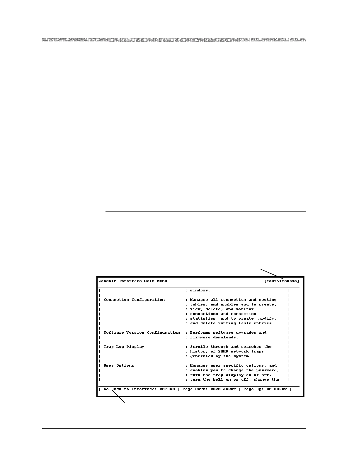
1 On the Console Interface Main Menu window (see Figu re 3-6), select the
Equipment Configuration option and press Enter.
Figure 3-6. Console Interface Main Menu (Equipment Configuration Selected)
The Equipment Configuration window (see Figure 3-7) is displayed.
PacketStar® 8-Port Voice 2-Wire Station Module User Guide, Issue 1 Release 8.0.0
3-8 255-700-261
Page 37

Chapter 3 Configuring Ports and Channels Using the Console Interface
Configuring the Module
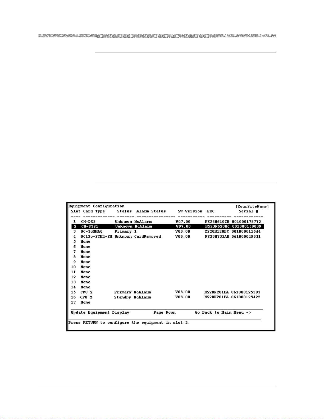
Figure 3-7. Equipment Configuration Window (As Displayed on the PSAX 1000,
PSAX 1250, PSAX 2300, and PSAX 4500 Console)
2 On the Equipment Configuration window, select the 8-Port
Vo ice 2-Wire Station.
PacketStar® 8-Port Voice 2-Wire Station Module User Guide, Issue 1 Release 8.0.0
255-700-261 3-9
Page 38

Chapter 3 Configuring Ports and Channels Using the Console Interface
Configuring the Module
The Two Wire Station Configuration window (see Figure 3-8) is displayed.
Figure 3-8. Two Wire Station Configuration Window
Commands Table 3-4 describes the commands on the window:
Table 3-4. Commands for the Two Wire Station Configuration Window
Command Function
Update Display Updates the values in the fields to show
the most current configuration. Use this
command mostly to display the most current information in the Line Status field.
Configure All Interfaces Sets all four ports to the circuit emulation
type interface. The value CircuitEmula-
tion is displayed in the Interface Type
field, and the value OutOfService is displayed in the Oper Status field.
Delete All Interfaces Deletes the conf i gu re d in te rf ac e s f or all
four ports. The value Unconfigured is
displayed in the Interface T ype and the
Oper Status fields.
Note: Y ou must first take all interfaces out
of service (using the Take All Interfaces
Out Of Service command) before you
can use this command to delete all the
configured interfaces.
PacketStar® 8-Port Voice 2-Wire Station Module User Guide, Issue 1 Release 8.0.0
3-10 255-700-261
Page 39

Chapter 3 Configuring Ports and Channels Using the Console Interface
Configuring the Module
Table 3-4. Commands for the Two Wire Station Configuration Window
Command Function
Bring All Interfaces Into
Service
Brings the out-of-service configured interfaces for all four ports to in-service status.
The value InService is displayed in the
Oper Status field for all four ports.
Take All Interfaces Out Of
Service
Takes the in-service configured interfaces
for all four ports to out-of-service status.
The value OutOfService is displayed in
the Oper Status field for all four ports.
Note: You must use this command first
before using the Delete All Interfaces
command.
Go Back to Equipment Configuration
Redisplays the Equipment Configurat ion
window.
3 To configure the port fields, do one of the following:
a. If you want to configu re all e i ght ports with the de fault p ort fi eld va l-
ues given in T able 3-6, select the Configure All Interfaces command
and press Enter.
The value CircuitEmulation is displayed in the Interface Type field, and
the value OutOfService is displayed in the Oper Status field.
b. To configure one port at a time (to set values other than the default
ones), select the line for the port you want to configure and press
Enter.
PacketStar® 8-Port Voice 2-Wire Station Module User Guide, Issue 1 Release 8.0.0
255-700-261 3-11
Page 40

Chapter 3 Configuring Ports and Channels Using the Console Interface
Configuring the Module
The Two Wire Station Port and Channel Configuration window (see
Figure 3-9) is displayed.
Figure 3-9. Two Wire Station Port and Channel Configuration window
Commands Table 3-5 describes the commands on the window:
Table 3-5. Commands for the Two Wire Station Port and Channel Configuration
Window
Command Function
Apply Port and Channel
Applies the configuration field values you set.
Configuration
Reset Port and Channel
Resets the fields to the last set of saved values.
Display
Bring Interface Into Ser-
vice
Brings an out-of-service configured interface
to in-service status. Command is displayed
when the [Oper Status] field is OutOfSer-
vice. The value InService is displayed in the
[Oper Status] field.
Take Interface Out of
Service
Takes an in-service configured interface to
out-of-service status. Command is displayed
when the [Oper Status] field is InService.
The value OutOfService is displayed in the
[Oper Status] field.
Configure Interface Displays the Circuit Emulation Interface Con-
figuration window.
Go Back to Card Configuration
Redisplays the Two Wire Station Configuration window.
PacketStar® 8-Port Voice 2-Wire Station Module User Guide, Issue 1 Release 8.0.0
3-12 255-700-261
Page 41

Chapter 3 Configuring Ports and Channels Using the Console Interface
Configuring the Module
4 Select the values for the fields on this window from the values given in
Table 3-6.
Table 3-6. Field Descriptions for the Two Wire Station Port and Channel Configuration Window
Field Name Field Values Description
Test Mode Default: None The module is not in test mode.
QuietTime Quiet Time is useful only if the line is not quiet
enough. If the line is noisy, the quiet time feature will
help you to determine whether the channel is noisy.
If noise is present on the line, then the channel is
defective.
Note: Do not select this value unless the line is noisy.
F-1004Hz A 1004 Hz tone is used in troubleshooting a system
where a line is seized by bridg ing throug h a resistance
the tip and ring wires.
[Signaling Bits]
(display only)
[Dial Mode]
Ab Signaling bits method supported is AB (two-bit signal-
ing).
Dtmf Dual tone multi-frequency
(display only)
[Loopback]
(display only)
[Loop Detect]
NoLoopback The ports on this module cannot be set up for loop-
back.
LoopStart Loop detection.
(display only)
[Ring Cadence]
(display only)
OneOnThreeOff The pattern of the signaling—one second on and
three seconds off.
PacketStar® 8-Port Voice 2-Wire Station Module User Guide, Issue 1 Release 8.0.0
255-700-261 3-13
Page 42

Chapter 3 Configuring Ports and Channels Using the Console Interface
Configuring the Module
Table 3-6. Field Descriptions for the Two Wire Station Port and Channel Configuration Window
Field Name Field Values Description
[Line Status]
(display only)
Indicates the Line Status of the
interface. It contains l oopback , fai lure, rece ived alar m
and transmitted alarm information.
See the bit map tables for the Voice 2-Wire Station
module under the MIB object li neStatus i n the appen dix, "SNMP Trap Messages" in the appropriate Packet-
Star PSAX Multiservice Media Gateway User Guide.
NoAlarm (default) No alarm is present.
RcvFarEndLOF Far-end loss of frame.
FarEndLOF Near-end sending loss of frame
indication.
RcvAIS Far-end sending alarm indication signal.
AIS Near-end sending alarm indication
signal.
LossOfFrame Near-end loss of frame.
LossOfSignal Near-end loss of signal.
LoopbackState Near-end is looped.
T16AIS E1 TS16 AIS.
Rcv
Far-end sending TS16 LOMF.
FarEndLOMF
FarEndLOMF Near-end sending TS16 LOMF.
RcvTestCode Near-end detects a test code.
OtherFailure Any line status not defined here.
RmtLoopback Far-end loopback.
Interface Type De fault:
This interface is not configured.
Unconfigured
Circuit Emulation This interface is configured for circuit emulation.
[Admin Status]
(display only)
InService Indicates that the no conditions are preventing the
port from being fully operational.
OutOfService Indicates that some condition is preventing the port
from being fully operational, such as a loss of signal to
the port; the port is not functioning at its full potential
though it is possible that connections can be made
[Oper Status]
(display only)
Unconfigured
(default)
This channel is not operational because the interface
is not configured.
InService This channel is capable of receiving and sending sig-
nals.
OutOfService This channel is not capable of receiving and sending
signals.
Connection Type Default: Pvc Permanent virtual circuit (PVC).
Svc Switched virtual circuit (SVC).
PacketStar® 8-Port Voice 2-Wire Station Module User Guide, Issue 1 Release 8.0.0
3-14 255-700-261
Page 43

Chapter 3 Configuring Ports and Channels Using the Console Interface
d
Saving the Equipment Configuration and Logging Off
Table 3-6. Field Descriptions for the Two Wire Station Port and Channel Configuration Window
Field Name Field Values Description
Service Type De fault: Plar Private line automatic ringdown. Use this only for
PVC connections.
Fxs Foreign exchange subscriber (FXS). Use this only for
PVC connections. Caller ID and flashhook signaling
support under FXS.
S-signaling Use this only for SVC connections.
[Silence Suppres-
Disabled, Enabled Silence suppression is enabled or disabled.
sion]
(display only)
[Echo Cancellation]
(display only)
Enabled The echo cancellation function is always enabled.
This function is a method for isolating and filtering
unwanted signal energy caused by echoes from the
main transmitted signal.
[Voice Compres-
None Voice compression is disabled.
sion]
(display only)
[Compandin g La w ]
(display only)
[AAL Encapsula-
MuLawPCM The PCM coding and companding standard used in
North Ameri ca an d J ap an .
Aal1 ATM Adaptation Layer 1 (AAL1)
tion]
(display only)
T o apply the values for the fields on this window, select the Apply Por t and
Channel Confi gu r atio n command and press Enter.
5 Select the Configure Interface command and press Enter.
The Circuit Emulation Interface Configuration window is displayed.
Note: For more information about configuring the Circuit Emulation
interface using the AC console, see Chapter 5.
6 Repeat steps 3–6 for the remainder of the ports, as needed.
Note: Whenever needed, use the commands in the Two Wire Station
Configuration window (see Figure 3-8) and on the Two Wire Station Port and Channel Configuration window (see Figure 3-9) to
manage the interfaces.
En
Saving the Equipment Configuration and Logging Off
PacketStar® 8-Port Voice 2-Wire Station Module User Guide, Issue 1 Release 8.0.0
255-700-261 3-15
Page 44

Chapter 3 Configuring Ports and Channels Using the Console Interface
Saving the Equipment Configuration and Logging Off
After configuring the module ports and channels, the interface types for each
port and channel, and the connections, you must save the values to the
PSAX system database. It is recommended that you save your values frequently as you progress through your work, at a minimum, after finishing
each stage of work:
• Configuring each module in your system
• Configuring the connections in your system
• Before exiting your current console session
Perform the following procedure to permanently save the values for your
system.
!
CAUTION:
If your system or location loses power or your current session ends
abnormally while you are in the process of configuring the system, and
you have not yet saved the values permanently , you will lose all unsaved
values you have applied on the various windows.
Returning to the Cons ole Interface Main Men u
Begin
1 To return to the Console Interface Main Menu window, press Ctrl+G.
On the Console Interface Main Menu window, [Modified] is displayed
next to the Save Configuration command, indicating you have made
changes to your system that are not yet saved to the dat abase.
2 Select the Save Configuration command.
Wait a few seconds while the system writes the values to the PSAX system database. The system displays the following message while it is executing this command:
Saving the equipment and connection information
When this function is completed, the system displays the following message:
T-SaveConfiguration: saveConfigurationReasonCode=All-OK
You can now safely exit the current session.
3 Select the Leave Console Interface command.
You are now logged off the PSAX system console interface.
End
PacketStar® 8-Port Voice 2-Wire Station Module User Guide, Issue 1 Release 8.0.0
3-16 255-700-261
Page 45

4 Configuring Interfaces Using the
Console Interface
Before You Beg i n
Before you can set interface configurat ion values , you mu st have s elected an
interface type value other than Unconfigured in the Interface Type field on
the 8-Port Voice 2-Wire Station module’s Port and Channel configuration
window.
This chapter provides instructions for configuring the circuit emulation interface type for the module using the Multiservice Media Gateway console.
Note: For a matrix of interface types by PSAX I/O module types, see the
Interface Types by I/O Module Types table in the appendix, “Reference Information.”
Errors When Applying Interfaces to Ports
An error may occur when you apply an interface to channel. If an error condition occurs, the PSAX system sends an SNMP trap that is usually displayed
in the console Trap Log Display window (accessible from the Console Interface Main Menu window). The list below includes the most common interface errors that cause the PSAX system to display a message. (See the appendix, “SNMP Trap Messages,” in the appropriate PacketStar PSAX Multiservice
Media Gateways user guide for more information about the SNMP traps
related to interface errors).
• Entering field values that are outside of the configurable range of values
• Attempting to configure an interface for a port or channel that has already
been configured
• Attempting to configure an interface that is already in service (must be out
of service to be configured or change field values)
• Entering field values that are not recognized by the PSAX system software
The Circuit Emulation Interface
Managing Circuit Emulation Interfaces
This section provides instructions for managing interfaces by performing the
following tasks:
• Configuring and applying interface(s)
• Bringing interface(s) into service
PacketStar® 8-Port Voice 2-Wire Station Module User Guide, Issue 1 Release 8.0.0
255-700-261 4-1
Page 46

Chapter 4 Configuring Interfaces Using the Console Interface
The Circuit Emulation Interfac e
• Taking interface(s) out of service
• Viewing interface(s)
• Deleting interface(s)
• Viewing interface statistics
Configuring a Circuit Emulation Interface
This section provides instructions for configuring an I/O module for the circuit emulation interface.
Begin
Note: To display the windows for configuring a circuit emulation inter-
face (see Figure 4-1), you must have completed the following
three steps in a previous procedure:
• Selected the value CircuitEmulation in the Interface Type field on the
appropriate Port and Channel, DS1 Channel, or Virtual DS1 Channel Configuration window of the module that you are configuring for circuit emulation.
Note: Channel strapping is done before the Apply Configuration step
below. (For instructions, see the Port and Channel Configuration
chapter of this guide).
• Selected the Apply Configuration command.
• Selected the Configure Interface command. The Circuit Emulation Inter-
face Configuration window (see Figure 4-1) is displayed. Table 4-1
describes the commands for the window. Table 4-2 describes the fields on
the window.
1 On the Circuit Emulation Interface Configuration wind ow, enter the val-
ues in the fields on this window according to the information provided in
Table 4-2.
2 Select the Apply Interf ac e Conf ig ur at i on co mm a n d to se t th e valus
you selected.
3 If your configuration requires you to bring the interface into service at
this time, do so by selecting the Bring Interface Into Service command. For more information on other configuration windows on which
you can bring interfaces into service, see the “Bringing One or More Circuit Emulation Interfaces into Service” procedure in this guide.
End
PacketStar® 8-Port Voice 2-Wire Station Module User Guide, Issue 1 Release 8.0.0
4-2 255-700-261
Page 47

Chapter 4 Configuring Interfaces Using the Console Interface
The Circuit Emulation Interface
Figure 4-1. Circuit Emulation Interface Configuration Window
Commands The commands on this window have the following functions:
Table 4-1. Commands for the Circuit Emulation Interface Window
Command Function
Bring Interface Into Service Brings an out-of-service configured inter-
face to in-service status. The value
InService is displayed in the [Admin Status] field.
Note: This command is displayed when
the [Admin Status] field is
OutOfService. You must first configure
the interface before you can use this command.
Take Interface Out of
Service
T akes an in-service configured interface to
out-of-service status. The val u e
OutOfService is displayed in the [Admin
Status] field.
Note: This command is displayed when
the [Admin Status] field is InService. You
must use this command first before using
the Delete Interface and Return com-
mand.
PacketStar® 8-Port Voice 2-Wire Station Module User Guide, Issue 1 Release 8.0.0
255-700-261 4-3
Page 48

Chapter 4 Configuring Interfaces Using the Console Interface
The Circuit Emulation Interfac e
Table 4-1. Commands for the Circuit Emulation Interface Window
Command Function
Add Interface Applies the configuration field values you
set.
Delete Interface and Return Deletes an out-of-service interface and
redisplays the Port and Channel Configuration window for the module you are
configuring.
Note: You must first take interface out of
service (using the T ake Interface Out of
Service command) before you can use
this command.
Go Back to Port Configuration
Redisplays the Port and Channel Configuration window of the module you are
configuring.
Table 4-2. Field Descriptions for the Circuit Emulation Interface Configuration Window
Field Names Field Values Description
With_Egress_Interface, Left Panel
Right Panel
[Admin Status]
(display only)
Default:
OutOfService
Indicates whether the interface is configured and
brought into service.
Range: N/A
Format: Predefin ed
OutOfService Indicates that the interface is not configured and
brought into service.
InService Indicates that the interface is configured and
brought into service.
[Oper Status]
(display only)
Default:
OutOfService
Indicates whether any condition is preventing the
interface from passing traffic.
Range: N/A
Format: predefin ed
alphanumeric
OutOfService Indicates that a condition is preventing the inter-
face from passing traffic.
InService Indicates that no condition is preventing the
interface from passing traffic.
Bringing a Circuit Emulation Interface Into Service
PacketStar® 8-Port Voice 2-Wire Station Module User Guide, Issue 1 Release 8.0.0
4-4 255-700-261
Page 49

Chapter 4 Configuring Interfaces Using the Console Interface
The Circuit Emulation Interface
Begin
Note: You may bring the Circuit Emulation interface into service from
either of these windows:
• the module port and channel configuration window, or
• the Circuit Emulation Interface Configuration Window.
Make sure that the module configuration is complete before bringing the
interface into service.
To bring the interface into service on the Circuit Emulation Interface Configuration Window, select the Bring Interface Into Service command, (or
press Ctrl+N).
The InService value is displayed in the [Admin Status] field.
End
Viewing the Parameters of a Specific Circuit Emulation Interface
Begin
The circuit emulation interface window is accessed for viewing by the
same navigational steps as the “Configuring an Interface...” procedure.
This path may vary depending on the module you used (see the Reference Information appendix in this guide for a list of what modules can be
used for the interfaces available). You should always view an interface
and determine whether you hav e chos en the corr ect one befo re you perform any of the procedures in step 2 below.
1 Return to the Console Inter face Main Menu for the module you config-
ured the Circuit Emulation interface on an d repea t the step s in the “Configuring a Circuit Emulation Interface” procedure in this guide until you
access the Circuit Emulation Interface Configuration window.
2 Proceed to one of the following sections, as needed:
• Bringing One or More ATM UNI Interfaces into Service
• Taking One or More ATM UNI Interfaces out of Service
• Deleting One or More ATM UNI Interfaces
End
Viewing the Circuit Emulation Module Port Statistics
T o view the Circuit Emulation in terface s tatistics , perfo rm the steps i n the following procedure.
PacketStar® 8-Port Voice 2-Wire Station Module User Guide, Issue 1 Release 8.0.0
255-700-261 4-5
Page 50

Chapter 4 Configuring Interfaces Using the Console Interface
d
The Circuit Emulation Interfac e
Begin
The Circuit Emulation Interface Statistics are viewed on the Port Statistics
window of the module you are using for the Circuit Emulation Interface.
Access this window from the module port and channel configuration window . See the appropriate module guide for more details on module port statistics windows.
Traffic must have passed on the connection before statistics will display.
End
Taking a Circuit Emulation Interface Out of Service
Note: You may take a Circuit Emulation interface out of service from
either of these windows:
• the module port and channel configuration window, or
• the Circuit Emulation Interface Configuration window.
Make sure that the module configuration is complete.
Begin
1 To take the interface out of service on the Circuit Emulation Interface
Configuration Window, select the Take Interface Out Of Service com-
mand (or press Ctrl+N).
On the Circuit Emulation Interface Configuration Window, the window
status line prompts:
Taking the interface down will lose all configurations. Continue? (y/n)
On the module Port and Channel Configuration window, the status line
prompts:
Are you SURE that you want to take ALL interfaces out of service? (y/n)
2 Select Y.
The OutOfService value is displayed in the [Admin Status] field.
En
Deleting a Circuit Emulation Interface
Begin
Note: You may delete the Circuit Emulation interface from either of
these windows:
• the module port and channel configuration window, or
PacketStar® 8-Port Voice 2-Wire Station Module User Guide, Issue 1 Release 8.0.0
4-6 255-700-261
Page 51

Chapter 4 Configuring Interfaces Using the Console Interface
The Circuit Emulation Interface
• the Circuit Emulation Interface Configuration Window. In either case, you
must first take the interface out of service.
T o delete the interface o n the Circuit Emulat ion Interface Co nfiguration Window , proceed as follows:
1 Select the Take Interface Out Of Service command.
On the module Port and Channel Configuration window, the window
prompt reads:
Are you SURE that you want to take ALL interfaces out of service? (y/n)
On the Circuit Emulation Interface Configuration window, the window
prompt reads:
Taking the interface down will cause all SVCs to be lost.
Continue? (y/n)
2 Type Y to continue.
The OutOfService value is displayed in the [Admin Status] field.
3 Select the Delete Interface and Return command and press Enter.
On the module Port and Channel Configuration window, the window
prompt reads:
Are you SURE that you want to take ALL interfaces out of service? (y/n)
On the Circuit Emulation Interface Configuration window, the window
prompt reads:
Are you SURE that you want to delete this interface? (y/n)
4 Press Y The interface is deleted and you are returned to the port and
channel configuration window.
End
Modifying a Circuit Emulation Interface
After you have configured an Circuit Emulation interface for a specified port
and channel, you cannot directly change the parameters for this interface
even if it is out of service. The concept for “modifying” (replacing) an Circuit
Emulation interface is that you delete the interface with the parameters you
no longer want for a specified port and channel, and then configure a new
interface for the same port and channel. Perform the following procedures in
the sequence shown to replace an Circuit Emulation interface that has
parameters you do not want.
Begin
1 On the Equipment Configuration window, select the module for which
you want to replace an interface.
2 Select the port and channel for the interface you want to replace.
PacketStar® 8-Port Voice 2-Wire Station Module User Guide, Issue 1 Release 8.0.0
255-700-261 4-7
Page 52

Chapter 4 Configuring Interfaces Using the Console Interface
d
The Circuit Emulation Interfac e
3 View the parameters of the interface you do not want to be sure you are
choosing the right one. See the procedure in the section, “Viewing the
Parameters for an Circuit Emulation Interface.”
4 Take the interface out of service. See the procedure in the section, “Tak-
ing One or More Circuit Emulation Interfaces Out of Service.”
Note: After you perform this step, the traffic flow on the connection
using the interface is stopped.
5 Delete the interface. See the procedure in the section, “Deleting One or
More Circuit Emulation Interfaces.”
Note: After you perform this step, the connection using the interface is
automatically deleted from the Connections database.
6 Configure a new interface. See the procedure in the section, “Configur-
ing a Circuit Emulation Interface.”
7 Bring the newly configured interface into service. See the procedure in
the section, “Bringing One o r Mor e Circuit E mulatio n int erfaces int o Service.”
End
Note: You now need to provision a new connection using the newly
En
Provisioning Connections
For instructions on configuring connections to t he 4-Port Voice 2-Wire Office
Module, see your PacketStar® PSAX Connections Provis ioning Guide for Packet-
®
PSAX Central Office Multiservice Media Gateways, Document No. 255-700-377.
Star
The module supports the following types of connections:
• PVC connections:
~ Circuit Emulation-to ATM virtual channel connection (VCC)
~ Circuit Emulation-to Circuit Emulation
• SPVC connections:
~ Circuit Emulation-to-ATM VCC
Before you provision connections for the modules, you must have first completed the following tasks:
• Set the configuration values for one or more ports on the module
• Set the configuration values for the various types of interfaces on the mod-
ule
configured interface for the same specified port and channel for
which you deleted the original interface (and connection). (See
the PacketStar PSAX System Connections Provisioning Guide for more
information.)
PacketStar® 8-Port Voice 2-Wire Station Module User Guide, Issue 1 Release 8.0.0
4-8 255-700-261
Page 53

Chapter 4 Configuring Interfaces Using the Console Interface
The Circuit Emulation Interface
PacketStar® 8-Port Voice 2-Wire Station Module User Guide, Issue 1 Release 8.0.0
255-700-261 4-9
Page 54

Chapter 4 Configuring Interfaces Using the Console Interface
The Circuit Emulation Interfac e
PacketStar® 8-Port Voice 2-Wire Station Module User Guide, Issue 1 Release 8.0.0
4-10 255-700-261
Page 55

5 Configuring Ports and Channels
Using the AQueView® EMS
Overview of This Chapter
This chapter describes how to use the AQueView EMS to perform the following tasks:
• Setting the values for the port and channel configuration of the 8-Port
Voice 2-Wire Station module
• Saving the module configuration and logging off
Using the Right-Click Menu
You can perform various functions in the AQueView system by clicking the
right mouse button. This section describes the right-click menu options you
can use in the various windows in the AQueView system when configuring
ports and channels.
Figure 5-1. Sample Port Configuration (Displaying Right-Click Menu)
Figure 5-2. Sample Channel Configuration (Displaying Right-Click Menu)
PacketStar® 8-Port Voice 2-Wire Station Module User Guide, Issue 1 Release 8.0.0
255-700-261 5-1
Page 56

Chapter 5 Configuring Ports and Channels Using the AQueView® EMS
d
Accessing Configuration Options
Option Function
Configure Opens the port and channel configuration
window of a module.
Bring All Interfaces Into
Service
Sets all configured interf aces on a channe l
administratively into service.
Take All Interfaces Out of
Service
Delete All Interfaces Deletes all configured interfaces that are
Channel Sele ct i on Opens the appropriate channel configura-
Accessing Configuration Options
You must first configure the 8-Port Voice 2-Wire Station module before you
can set up connection provisioning.
Perform the steps in the following procedure to access the port and channel
configuration functions in the AQueView EMS.
Begin
1 Log in to the AQueView system as a user with Administrator or Configu-
rator access privileges.
Takes all configured interfaces on a channel administratively out of service.
not in service. To delete interfaces, you
must first take them administratively out
of service.
tion window for the selected channel.
2 From the Device List or the Open Device window (press Ctrl+D or
Ctrl+O), open the PSAX device that contains the module on which you
want to configure a port or channel.
The PSAX device that you opened appears in the Front Panel, and its
components are also displayed in the Device Tree (see Figure 5-3).
En
PacketStar® 8-Port Voice 2-Wire Station Module User Guide, Issue 1 Release 8.0.0
5-2 255-700-261
Page 57

Chapter 5 Configuring Ports and Channels Using the AQueView® EMS
Configuring the Module
Figure 5-3. Device Tree and Device Window (Displaying a Typical Setup)
Configuring the Module
To configure the ports of a 8-Port Voice 2-Wire Station, perform the steps in
the following procedure.
Begin
1Do one of the following to open the Port and Channel Configuration win-
dow:
• In the Front Panel, double-click the port to be viewed or configured.
• In the Front Panel, right-click the port and a menu appears. Select
Configure.
• In the Device Tree, double-click the desired port symbol or identifier.
• In the Device Tree, select a port, then right-click the icon for the mod-
ule within Device Tr ee and a menu appears. Select Configure.
PacketStar® 8-Port Voice 2-Wire Station Module User Guide, Issue 1 Release 8.0.0
255-700-261 5-3
Page 58

Chapter 5 Configuring Ports and Channels Using the AQueView® EMS
Configuring the Module
Figure 5-4. Front Panel View of the Voice 2-Wire Station Module
The 2-Wire Station Port and Channel Configuration window opens (see
Figure 5-5).
2 Select the values for the fields as described in Table 5-1.
3 Click Apply.
End
PacketStar® 8-Port Voice 2-Wire Station Module User Guide, Issue 1 Release 8.0.0
5-4 255-700-261
Page 59

Chapter 5 Configuring Ports and Channels Using the AQueView® EMS
Configuring the Module
Figure 5-5. 2-Wire Station Port and Channel Configuration Window
This window contains:
~ The Port Configuration page, which lets you do the following:
• Select and apply port settings
• View port statistics, which display line errors and coding violations
~ The Channel Configuration page, which lets you do the following:
• Select and apply an interface
• Open the Interface Configuration window to configure the interface
• Channel Configuration panel for entering the interface type and dis-
playing the operational status, connection and service type, silence
suppression, echo cancellation, voice suppression, companding law,
and AAL Encapsulation. Once the interface is selected and applied,
interface parameters can be in the Interface Parameters window.
Note: All interface s must be out o f se rvice befo re ch ange s c an be ma de to
the port settings; otherwise, the Apply button will appear to be
ghosted.
The buttons on this window have the following functions:
PacketStar® 8-Port Voice 2-Wire Station Module User Guide, Issue 1 Release 8.0.0
255-700-261 5-5
Page 60

Chapter 5 Configuring Ports and Channels Using the AQueView® EMS
Configuring the Module
Button Function
Close Closes this window.
Apply Applies the configuration field value you set.
Reset Resets the fields to the last set of applied values.
Copy Copies the port configuration to a range of ports.
Table 5-1. Field Descriptions for the Two Wire Station Port and Channel Configuration Window
Field Name Field Values Description
Test Mode Default: Off The module is not in test mode.
QuietTime Quiet Time is useful only if the line is not quiet
enough. If the line is noisy, the quiet time feature will
help you to determine whether the channel is noisy.
If noise is present on the line, then the channel is
defective.
Note: Do not select this value unless the line is noisy.
F-1004Hz A 1004 Hz tone is used in troubleshooting a system
where a line is seized by bridg ing throug h a resistance
the tip and ring wires.
Signaling Bits (display only)
Dial Mode
Ab Signaling bits method supported is AB (two-bit signal-
ing).
Dtmf Dual tone multi-frequency
(display only)
Loopback
(display only)
Loop Detect (dis-
NoLoopback The ports on this module cannot be set up for loop-
back.
LoopStart Loop detection.
play only)
Ring Cadence (dis-
play only)
OneOnThreeOff The pattern of the signaling—one second on and
three seconds off.
PacketStar® 8-Port Voice 2-Wire Station Module User Guide, Issue 1 Release 8.0.0
5-6 255-700-261
Page 61

Chapter 5 Configuring Ports and Channels Using the AQueView® EMS
Configuring the Module
Table 5-1. Field Descriptions for the Two Wire Station Port and Channel Configuration Window
Field Name Field Values Description
Line Status
(display only)
Indicates the Line Status of the
interface. It contains l oopback , fai lure, rece ived alar m
and transmitted alarm information.
See the bit map tables for the Voice 2-Wire Station
module under the MIB object li neStatus i n the appen dix, "SNMP Trap Messages" in the appropriate Packet-
Star PSAX Multiservice Media Gateway User Guide.
NoAlarm (default) No alarm is present.
RcvFarEndLOF Far-end loss of frame.
FarEndLOF Near-end sending loss of frame
indication.
RcvAIS Far-end sending alarm indication signal.
AIS Near-end sending alarm indication
signal.
LossOfFrame Near-end loss of frame.
LossOfSignal Near-end loss of signal.
LoopbackState Near-end is looped.
T16AIS E1 TS16 AIS.
Rcv
Far-end sending TS16 LOMF.
FarEndLOMF
FarEndLOMF Near-end sending TS16 LOMF.
RcvTestCode Near-end detects a test code.
OtherFailure Any line status not defined here.
RmtLoopback Far-end loopback.
Interface Type De fault:
This interface is not configured.
Unconfigured
Circuit Emulation This interface is configured for circuit emulation.
Connection Type Default: Pvc Permanent virtual circuit (PVC).
Svc Switched virtual circuit (SVC).
Service Type De fault: Plar Private line automatic ringdown. Use this only for
PVC connections.
Fxs Foreign exchange subscriber (FXS). Use this only for
PVC connections. Caller ID and flashhook signaling
support under FXS.
Silence Suppression
Disabled, Enabled Silence suppression is enabled or disabled.
(display only)
Echo Cancellation
(display only)
Enabled The echo cancellation function is always enabled.
This function is a method for isolating and filtering
unwanted signal energy caused by echoes from the
main transmitted signal.
PacketStar® 8-Port Voice 2-Wire Station Module User Guide, Issue 1 Release 8.0.0
255-700-261 5-7
Page 62

Chapter 5 Configuring Ports and Channels Using the AQueView® EMS
Configuring the Module
Table 5-1. Field Descriptions for the Two Wire Station Port and Channel Configuration Window
Field Name Field Values Description
Voice Compression
None Voice compression is disabled.
(display only)
Companding Law
(display only)
AAL Encapsulation
MuLawPCM The PCM coding and companding standard used in
North Ameri ca an d J ap an .
Aal1 ATM Adaptation Layer 1 (AAL1)
(display only)
Configuring Channels
Applying an Interface to a Channel
To apply an interface to a channel on the 8-Port Voice 2-Wire Station, perform the steps in the following procedure.
Begin
1 Click the Channel Configuration tab
The Channel Configurat io n pa ge appe a rs (se e Figu re 5-6).
Figure 5-6. Channel Configuration Page
PacketStar® 8-Port Voice 2-Wire Station Module User Guide, Issue 1 Release 8.0.0
5-8 255-700-261
Page 63

Chapter 5 Configuring Ports and Channels Using the AQueView® EMS
Configuring the Module
The buttons on this window have the following functions:
Button Function
Apply to Selecte d Applies the configuration field value you set.
Close Closes this window.
2 In the Channel Configura tion page, eith er click the arro w in the Interface
Type field (in the middle of the window) or double-click the channel in
the Interface Type field.
3 Select CircuitEmulation in the Interface Type field.
4 Click Apply to Selected.
End
PacketStar® 8-Port Voice 2-Wire Station Module User Guide, Issue 1 Release 8.0.0
255-700-261 5-9
Page 64

Chapter 5 Configuring Ports and Channels Using the AQueView® EMS
Configuring the Module
PacketStar® 8-Port Voice 2-Wire Station Module User Guide, Issue 1 Release 8.0.0
5-10 255-700-261
Page 65

6 Configuring Interfaces Using the
Before You Beg i n
Before you can set interface configurat ion values , you mu st have s elected an
interface type value other than Unconfigured in the Interface Type field on
the 8-Port Voice 2-Wire Station module’s Port and Channel configuration
window.
AQueView® EMS
This chapter provides instructions for configuring the circuit emulation interface type for the module using the AQueView
Errors Applying Interfaces to Ports
An error may occur when you apply an interface to channel.
• Entering field values that are outside of the configurable range of values
• Attempting to configure an interface for a port or channel that has already
been configured
• Attempting to configure an interface that is already in service (must be out
of service to be configured or change field values)
The Circuit Emulation Interface
This section provides instructions for configuring an I/O module for the circuit emulation interface.
After applying the CircuitEmulation interface type to a channel from the
Channel Configuration page, do one of the following to access the Circuit
Emulation Interface Configuration window:
~ Double-click the left mouse button on the channel for which you want
to configure the interface.
~ Click the right mouse button on the channel for which you want to con-
figure the interface and a menu appears. Select Configure in the menu.
The Circuit Emulation Interface Configuration window appears (see
Figure 6-1).
®
element management system.
PacketStar® 8-Port Voice 2-Wire Station Module User Guide, Issue 1 Release 8.0.0
255-700-261 6-1
Page 66

Chapter 6 Configuring Interfaces Using the AQueView® EMS
The Circuit Emulation Interfac e
Figure 6-1. Circuit Emulation Interface Configuration Window
The buttons on this window have the following functions:
Button Function
Retrieve from NSAP database If you have previously established an
NSAP address database, click this button
to retrieve an entry from this list to populate the Local NSAP Address (Hex)
field.
Calculate Navis NSAP Address Displays only when you configure user
properties to include the Navis NSAP
format. For more information, see the
appropriate Navis AQueView Element
Management System User Guide.
Automatically calculates the local NSAP
address, and populates the NSAP
address in the NSAP Address (Hex) field
using the Navis algorithm for the slot,
port, and channel selected in the fields
on the bottom right panel.
PacketStar® 8-Port Voice 2-Wire Station Module User Guide, Issue 1 Release 8.0.0
6-2 255-700-261
Page 67

Chapter 6 Configuring Interfaces Using the AQueView® EMS
The Circuit Emulation Interface
Button Function
Bring Into Service Displays when the Administrative Status
field is OutOfService. Brings an out-ofservice configured interface to in-service
status. The value InService appears in
the Administrative Status field.
You must first configure the interface
before you can use this button.
Take Out of Service Displays when the Administrative Status
field is InService. Takes an in-service
configured interface to out-of-service
status. The value OutOfService
appears in the Administrative Status
field.
You must use this command first before
clicking the Delete.
Delete Deletes an out-of-service interface and
redisplays the Port and Channel Configuration window for the module you are
configuring.
You must first take interface out of service (by clicking Take Out of Service)
before you can use this button.
Copy Copies this interface to a range of slots,
ports, and channels.
Configure H248 TID Displays the H.248 Termination ID Con-
figuration window. For more information on using this module with H.248,
see the H.248 Media Gateway Control User
®
Guide for th e PacketSt ar
PSAX Multiservice
Media Gateways.
Close Closes this window.
Apply Applies the configuration field value
you set.
Reset Resets the fields to the last set of applied
values.
PacketStar® 8-Port Voice 2-Wire Station Module User Guide, Issue 1 Release 8.0.0
255-700-261 6-3
Page 68

Chapter 6 Configuring Interfaces Using the AQueView® EMS
The Circuit Emulation Interfac e
Button Function
Calculate Navis NSAP
Address
Note: This button appears only when you
configure user properties to include the
Navis NSAP format. For more information, see the appropriate Navis™ AQueView
Element Management System User Guide.
Automatically calculates the local NSAP
address, and populates the NSAP address
in the NSAP Address (Hex) field using the
Navis algorithm for the slot, port, and
channel selected in the fields on the bottom right panel.
Bring Into Service Displays when the Administrative Status
field is OutOfService. Brings an out-ofservice configured interface to in-service
status. The value InService displays in
the Administrative Status field.
You must first configure the interface
before you can use this button.
Take Out of Service Displays when the Administrative Status
field is InService. Takes an in-service configured interface to out-of-service status.
The value OutofService displays in the
Administrative Status field.
You must use this button first before using
the Delete button.
Delete Deletes an out-of-serv ice interface and
redisplays the Port and Channel Configuration window for the module you are
configuring.
You must fi rst tak e inte rface o ut of s ervice
(using the Take Out of Service button)
before you can use the Delete button.
Copy Copies this interface to a range of slots,
ports, and channels.
Configure H248 TID Displays the H.248 Termination ID Config-
uration window . For more information on
using this module with H.248, see the
H.248 Media Gateway Control User Guide for
®
the PacketStar
PSAX Multiservice Media
Gateways.
Close Closes this window.
PacketStar® 8-Port Voice 2-Wire Station Module User Guide, Issue 1 Release 8.0.0
6-4 255-700-261
Page 69

Chapter 6 Configuring Interfaces Using the AQueView® EMS
Button Function
Apply Applies the configuration field value you
Reset Resets the fields to the last set of applied
Configuring Circuit Emulation Interface Values
T o s et the val ue s fo r the Ci rc uit Emu la tio n inte rf ace , p erfo rm the s teps i n the
following procedure.
Begin
1 To configure the Local NSAP Address (Hex ) field, perform the steps in
the section, “Adding NSAP Addresses,” in this chapter, and then return
to this procedure.
2 To apply the interface configuration values, including the NSAP address
configuration, click Apply.
The Circuit Emulation Interface
set.
values.
End
Table 6-1. Field Descriptions for the Circuit Emulation Interface Configuration Window
Field Names Field Values Description
Interface Type Default: N/A
Circuit Emulation displays as the interface typ e.
Range: N/A
Format: predefin ed
alphanumeric
Signaling Default: CCS Clear
Channel signaling
Range: N/A
Format: predefin ed
alphanumeric
The type of signaling used.
Note: This field is displayed only when configur-
ing the circuit emulation interface on these mod-
ules:
• 6-Port Multiserial
• 6-Port Enhanced DS1 Multiservice
• 1-Port Channelized DS3
CCS Clear Channel
signaling
CAS (channel-associated signaling)
Clear channel signaling—ABCD signaling bits not
used.
Channel associated signaling—signaling bit trans-
port based on ATM Forum stardard for ABCD sig-
naling bits. ISDN requires the use of the whole
port. Will not function with CAS.
PacketStar® 8-Port Voice 2-Wire Station Module User Guide, Issue 1 Release 8.0.0
255-700-261 6-5
Page 70

Chapter 6 Configuring Interfaces Using the AQueView® EMS
Provisioning Connections
Table 6-1. Field Descriptions for the Circuit Emulation Interface Configuration Window
Field Names Field Values Description
Speed Adaptation Default: Enabled
Range: N/A
Refers to robbed-bit signaling in circuit emulation
interfaces.
Format: predefin ed
alphanumeric
Disabled Refers to robbed-bit signaling in circuit emulation
interfaces.
[Admin Status]
(display only)
Default:
OutOfService
Indicates whether the interface is configured and
brought into service or not.
Range: N/A
Format: Predefin ed
OutOfService The interface is not configured and brought into
service.
InService The interface is configured and brought into ser-
vice.
[Oper Status]
(display only)
Default:
OutOfService
Indicates whether any condition is preventing the
interface from passing traffic.
Range: N/A
Format: predefin ed
alphanumeric
OutOfService Indicates that a condition is preventing the inter-
face from passing traffic.
InService Indicates that no condition is preventing the
interface from passing traffic.
Local NSAP Address
(Hex)
Default:
Hexadecimal
Range: N/A
The ATM NSAP address of the local end of the
connection, in hexadecimal notation. Enter the
NSAP address of the local ATM interface.
Format: Hexadecimal
Provisioning Connections
For instructions on configuring connections to the Voice 2-Wire Office module, see your PacketStar® PSAX Connections Provisioning Guide for PacketStar
PSAX Central Office Multiservice Media Gateways, Document No. 255-700-377.
The module supports the following types of connections:
• PVC connections:
~ Circuit Emulation-to ATM virtual channel connection (VCC)
~ Circuit Emulation-to Circuit Emulation
• SPVC connections:
~ Circuit Emulation-to-ATM VCC
PacketStar® 8-Port Voice 2-Wire Station Module User Guide, Issue 1 Release 8.0.0
6-6 255-700-261
®
Page 71

Chapter 6 Configuring Interfaces Using the AQueView® EMS
Provisioning Conn ec tio ns
Before you provision connections for the modules, you must have first completed the following tasks:
• Set the configuration values for one or more ports on the module
• Set the configuration values for the various types of interfaces on the mod-
ule
PacketStar® 8-Port Voice 2-Wire Station Module User Guide, Issue 1 Release 8.0.0
255-700-261 6-7
Page 72

Chapter 6 Configuring Interfaces Using the AQueView® EMS
Provisioning Connections
PacketStar® 8-Port Voice 2-Wire Station Module User Guide, Issue 1 Release 8.0.0
6-8 255-700-261
Page 73

A Wiring Configurations
Purpose of this Appendix
This appendix shows the RJ-12 wiring configuration for the Voice 2-Wire
Station module.
Figure A-1. RJ-12 Wiring Configuration
PacketStar® 8-Port Voice 2-Wire Station Module User Guide, Issue 1 Release 8.0.0
255-700-261 A-1
Page 74

Appendix A Wiring Configurations
Purpose of this Appendix
PacketStar® 8-Port Voice 2-Wire Station Module User Guide, Issue 1 Release 8.0.0
A-2 255-700-261
Page 75

B Reference Information
Overview of This Appendix
This appendix contains reference tables that are helpful while configuring
your PSAX Multiservice Media Gateway system. The following types of information are provided:
• DSP Tone Detection Modes Table
• DSP2C Module Channel Reduction When Using Fax Relay Mode Table
• Industry Compliance Specifications Table
• Connection Types by Interfaces Type Table
• Interface Types by I/O Module Types Table
• Module Alarm Status Table
• Quality of Service (QoS) Information Tables
Call Tone Detection Settings
Table B-1. DSP Tone Detecti on Modes* and Associated Processing Performed
Tone Mode Processing Performed
Disabled Ignores fax tones and modem tones
Bypass If a fax tone or modem tone is received, the firmware switches to G.711 mode
(64 Kbps) and bypasses echo cancellation, if enough bandwidth is available.
Fax Relay If a fax tone is received, the firmware switches to a channel configured for
FaxRelayMode and performs fax demodulation / remodulation. If a modem
tone is received, the firmware ignores it
Fax Relay /Modem
Bypass
*
Modes selected on the Circuit Emulation-to-ATM VCC PVC Connection window
If a fax tone is received, the firmware switches to a channel configured for
FaxRelayMode and performs fax demodulation/remodulation. If a modem
tone is received, the firmware switches to G.711 mode (64 Kbps) and
bypasses echo cancellation, if enough bandwidth is available.
DSP Channel Reduction Availability Due to Fax Relay Mode
PacketStar® 8-Port Voice 2-Wire Station Module User Guide, Issue 1 Release 8.0.0
255-700-261 B-1
Page 76

Appendix B Reference Information
Industry Compliance Specifications
Table B-2. Channel Reduction Availability Caused by Fax Relay Connections vs.
Voice Processing Connections on a DSP2C Module
Number
of DSPs
for Fax
Relay
Total Connections
Assigned for
Fax Relay
Percent of All DSP
Connections
Assigned for Fax
Relay
Remaining Voice
Processing Available
Channels
*
14 3% 124
28 6% 120
312 9% 116
4 16 13% 112
5 20 16% 108
6 24 19% 104
7 28 22% 100
8 32 25%
†
96
936 28% 92
10 40 31% 88
11 44 34% 84
12 48 38% 80
13 52 41% 76
14 56 44% 72
15 60 47% 68
16 64 50% 64
*
For every fax transmission call, both the originally assigned DSP resource, plus
the fax relay DSP resource, are consumed for the duration of the call. Thus,
the total remaining DSP connections is reduced by twice the number of connections using fax mode service.
†
Utilization of DSP resources for fax relay above 25% is not considered realistic
for most service provider environments. If this value exceeds 25%, then the
number of available DSP connections for pure voice mode calls is reduced to
less than 50% of connections available on the DSP2C module .
Industry Compliance Specifications
Compliance specifications for the PacketStar® PSAX Multiservice Media Gateways I/O and server modules are contained in Table B-3.
PacketStar® 8-Port Voice 2-Wire Station Module User Guide, Issue 1 Release 8.0.0
B-2 255-700-261
Page 77

Appendix B Reference Information
Industry Compliance Specifications
Table B-3. Industry Compliance Specifications
Feature Name/Product Name Specification Title Notes
ATM Maintenance Mode
In-band Management SVC
af-pnni-0066000
Private Network-Netw ork Inte r-
face (PNNI) Addendum (Soft
PVC)
Traffic Management (UPC Support)
Route Server-to-ATM
af-tm-0121.000
T raffic Management, Usage
Parameter Control
Route Server-to-ATM
Interworking: Section 5.5
Interworking
GR-303 DLC Services
VTOA AAL2 Trunking Narrowband Services
af-vmoa-0145.000
Voice and Multimedia Over
ATM–Loop Emulation Service
Using AAL2
AAL2 Trunking af-vtoa-0089.000
ATM Trunking Using AAL1 for
Narrow Band Services V1.0
I.610 OAM F4/F5 Processing
(remote defect indication [RDI]
af-vtoa-0098.000
VTOA AAL1 Trunking Services
and alarm indication signal
[AIS])
af-vtoa-0119.000
Low Speed Circuit Emulation
Service
GR-303 DLC Services ANSI T1.401
Interface Between Carriers and
Customer Installations- Analog
Voice Grade Switched Access
Lines Using Loops-start and
Ground-start Signaling
GR-303 DLC Services ANSI T1.405
Network-to-customer Installation Interfaces- Direct-inward
Dialing Analog Voice Grade
Switched Access Using Loopreverse Battery Signaling
GR-303 DLC Services ANSI T1.409
Network-to-Customer Installation Interfaces- Analog Voice
Grade Special Access Lines Using
E&M Signaling
PacketStar® 8-Port Voice 2-Wire Station Module User Guide, Issue 1 Release 8.0.0
255-700-261 B-3
Page 78

Appendix B Reference Information
Industry Compliance Specifications
Table B-3. Industry Compliance Specifications (Continued)
Feature Name/Product Name Specification Title Notes
GR-303 DLC Services
VTOA AAL2 Trunking Narrow-
band Services
ANSI T1.602
Integrated Services Digital Net-
work (ISDN)- Data-link Layer
Signaling Specification for
Application at the User-Network
Interface
GR-303 DLC Services
VTOA AAL2 Trunking Narrow-
band Services
ANSI T1.607; T1.607a
Digital Subscriber Signaling Sys-
tem Number 1 (DSS1)-Layer 3
T1.607a is for GR-303 DLC Services
Signaling Specification for Circuit-switched Bearer Services
DSL Forum TR 017
A TM over ADSL Recommenda-
tions
GR-303 DLC Services
VTOA AAL2 Trunking Narrow-
band Services
EIA-464-B
Requirements for Private
Branch Exchange (PBX) Switching Equipment
ETSI 300 012-1
Integrated Services Digital Net-
work (ISDN); Basic User-Network Interface; Layer 1 Specification and Test Principles
ETSI ISDN Support ETSI 300 125 Annex C: Soft PVC Procedures
ETSI 300 324-1
V5.1 Interface for the Support of
Access Network (AN) Part 1:
V5.1 Interface Specification
ITU-T G. 964 and G.965 are
functionally equivalent to ETSI
EN 300 324-1 and ETSI EN 300
347-1 respectively. In cases
where detail differences exist
between the ITU-T and ETSI
versions of the specifications,
the ETSI versions of the specifications should apply.
ETSI 300 347-1
V5.2 Interface for the Support of
Access Network (AN) Part 1:
V5.2 Interface Specification
ITU-T G. 964 and G.965 are
functionally equivalent to ETSI
EN 300 324-1 and ETSI EN 300
347-1 respectively. In cases
where detail differences exist
between the ITU-T and ETSI
versions of the specifications,
the ETSI versions of the specifications should apply.
PacketStar® 8-Port Voice 2-Wire Station Module User Guide, Issue 1 Release 8.0.0
B-4 255-700-261
Page 79

Appendix B Reference Information
Industry Compliance Specifications
Table B-3. Industry Compliance Specifications (Continued)
Feature Name/Product Name Specification Title Notes
ETSI 300 402-1
Integrated Services Digital Net-
work (ISDN), Digital Subscriber
Signaling System No. 1 (DSS1)
Protocol; Data Link Layer, Part
1: General Aspects
ETSI 300 402-2
Integrated Services Digital Net-
work (ISDN); Digital Subscriber
System No. 1 (DSS1) protocol;
Data Link Layer, Part 2: General
Protocol Specification
GR-820-CORE
OTGR Section 5.1 Generic
Transmission Surveillance
I.610 OAM F4/F5 Processing
(remote defect indication [RDI]
and alarm indication signal
[AIS])
TR-NWT-00170
Bellcore Digital Cross-Connect
System Generic Requirements
and Objectives
IETF RFC 1157
Simple Network Management
Protocol (SNMP) Version 1.0
IETF RFC 1595
Definitions of Managed Objects
for the SONET/SDH Interface
Types
IETF RFC 1661
Point-to-Point Protocol
IETF RFC 1662
PPP in HDLC-like Framing
IETF RFC 1700
Assigned Numbers
IETF RFC 2364
PPP Over AAL5
ITU-T E.164
Overall Network Operation,
telephone service, service operation, and human factors: Operation, numbering, routing and
mobile services
International operat ion- Nu mbering plan of the international
telephone service
PacketStar® 8-Port Voice 2-Wire Station Module User Guide, Issue 1 Release 8.0.0
255-700-261 B-5
Page 80

Appendix B Reference Information
Industry Compliance Specifications
Table B-3. Industry Compliance Specifications (Continued)
Feature Name/Product Name Specification Title Notes
ITU-T G.702
General Aspects of Digital Trans-
mission Systems— Terminal
Equipment: Digital Hierarchy
Bit Rates
1.544 Mbps, 2.048 Mbps,
44.736 Mbps; includes channelassociated signaling (CAS)
ABCD in-band signaling
ITU-T G.704
Synchronous frame structures
used at 1544, 6312, 2048, 8488
and 44 736 Kbps hierarchical
levels
ITU-T G.706
Frame alignment and cyclic
redundancy check (CGC) procedures relating to basic frame
structures defined in Recommendation G.704
ITU-T G.707
Transmission Systems and
Media—Digital transmission systems— Terminal equipment—
General: Network node interface
for the synchronous digital hierarchy (SDH)
Annex A: Voice compression (8
Kbps)
Annex B: Silence suppression
ITU-T G.729
General Aspects of Digital Trans-
mission Systems: Coding of
Speech at 8 Kbps Using Conjugate-Structure Algebraic-CodeExcited Linear-Prediction (CSACELP)
ITU-T G.732
General Aspects of Digital Trans-
mission Systems Terminal
Equipments: Characteristics of
Primary PCM Multiplex Equipment Operating at 2048 Kbit/s
ITU-T G.736
General Aspects of Digital Trans-
mission: Characteristics of a
Synchronous Digital Multiplex
Equipment Operating at 2048
kbits/sec
PacketStar® 8-Port Voice 2-Wire Station Module User Guide, Issue 1 Release 8.0.0
B-6 255-700-261
Page 81

Appendix B Reference Information
Industry Compliance Specifications
Table B-3. Industry Compliance Specifications (Continued)
Feature Name/Product Name Specification Title Notes
ITU-T G.751
Digital multiplex equipments
operating at the third order bit
rate of 34 368 kbit/s and the
fourth order bit rate of 139 264
Kbps and using positive justification
ITU-T G.823
The control of jitter and wander
within digital networks which
are based on the 2048 Kbps
hierarchy
Includes Multiplex Section Protection (MSP)
ITU-T G.832
Transmission Systems and
Media, Digital Systems and Networks— Digital transmission
systems—Digital networks—
Network capabilities and functions: Transport of SDH Elements on PDH Networks—Frame and Multiplexing
Structures
Intra-office and short haul ITU-T G.957
Long haul not supported
Optical interfaces for equipment
and systems relating to the synchronous digital hierarchy
ITU-T G.964
V-Interfaces at the Digital Local
Exchange (LE)- V5.1 Interface
(based on 2048 Kbps) for the
Support of Access Network (AN)
ITU-T G. 964 and G.965 are
functionally equivalent to ETSI
EN 300 324-1 and ETSI EN 300
347-1 respectively. In cases
where detail differences exist
between the ITU-T and ETSI
versions of the specifications,
the ETSI versions of the specifications should apply.
ITU-T G.965
V-Interfaces at the Digital Local
Exchange (LE) - V5.1 Interface
(based on 2048 Kbps) for the
Support Of Access Network
(AN)
ITU-T G. 964 and G.965 are
functionally equivalent to ETSI
EN 300 324-1 and ETSI EN 300
347-1 respectively. In cases
where detail differences exist
between the ITU-T and ETSI
versions of the specifications,
the ETSI versions of the specifications should apply.
PacketStar® 8-Port Voice 2-Wire Station Module User Guide, Issue 1 Release 8.0.0
255-700-261 B-7
Page 82

Appendix B Reference Information
Industry Compliance Specifications
Table B-3. Industry Compliance Specifications (Continued)
Feature Name/Product Name Specification Title Notes
ITU-T G.991.2
Draft: Single-pair high speed
digital subscriber line (SHDSL)
transceivers
ITU-T G.992.1
Asymmetric Digital Subscriber
Line (ADSL) transceivers
ITU-T G.992.2
Splitterless Asymmetric Digital
Subscriber Line (ADSL) transceivers
ITU-T H.248
Annex E.2
H.248 Base Root Package
ITU-T I.121
Integrated Services Digital Network (ISDN) General Structure
and Service Capabilities: Broadband Aspects of ISDN
ITU-T I.150
B-ISDN ATM Functional charac-
teristics
ITU-T I.321
Integrated Services Digital Network (ISDN) Overall Network
Aspects and Functions, IS DN
User-Network Interfaces: BISDN Protocol Reference Model
and its Application
ITU-T I.356
ABR not supported
B-ISDN ATM layer cell transfer
performance
I.610 OAM F4/F5 Processing
(remote defect indication [RDI]
ITU-T I.361
B-ISDN ATM Layer Specification
and alarm indication signal
[AIS])
ITU-T I.363
B-ISDN ATM Adaptation Layer
Only AAL1, AAL2, and AAL5
are supported
specification
ITU-T I.363.1
B-ISDN ATM Adaptation Layer
specification: Type 1 AAL
PacketStar® 8-Port Voice 2-Wire Station Module User Guide, Issue 1 Release 8.0.0
B-8 255-700-261
Page 83

Appendix B Reference Information
Industry Compliance Specifications
Table B-3. Industry Compliance Specifications (Continued)
Feature Name/Product Name Specification Title Notes
Multiplexing support ITU-T I.363.2
B-ISDN ATM Adaptation Layer
specification: Type 2 AAL
ITU-T I.363.5
B-ISDN ATM Adaptation Layer
specification: Type 5 AAL
VTOA AAL2 Trunking Narrowband Services
ITU-T I.366.1
Segmentation and Reassembly
Service Specific Convergence
Sublayer for the AAL type 2
ITU-T I.372
Integrated Services Digital Net-
work (ISDN) Overall Network
Aspects and Functions: Frame
Relaying Bearer Service Network-to-Network Interface
Requirements
ITU-T I.413
Integrated Services Digital Net-
work (ISDN) User-Network
Interfaces: B-ISDN User-Network Interface
ITU-T I.430
Basic User-Network Interface -
Layer 1 Specification
Scrambling, header error control
(HEC) processing, cell delineation
ITU-T I.432
B-ISDN User-Network Inter-
face—Physical layer Specification
ITU-T I.432.1
B-ISDN User-Network Inter-
face: Physical Layer Specification- General Characteristics
ITU-T I.432.2
B-ISDN User-Network- Physical
Layer Specification: 155 520
Kbps and 622 080 Kbps operation
ITU-T I.432.3
B-ISDN User-Network Inter-
face: Physical Layer Specification for 1.544 Mbps and 2.048
Mbps
PacketStar® 8-Port Voice 2-Wire Station Module User Guide, Issue 1 Release 8.0.0
255-700-261 B-9
Page 84

Appendix B Reference Information
Industry Compliance Specifications
Table B-3. Industry Compliance Specifications (Continued)
Feature Name/Product Name Specification Title Notes
ITU-T I.432.4
B-ISDN User-Network- Physical
Layer Specification: 51 840 Kbps
Operation
ITU-T Q.922
Annex A
Digital Subscriber Signaling System No.1 (DSS 1) Data Link
Layer: ISDN Data Link Layer
Specification for Frame Mode
Bearer Servic es
ITU-T Q.921
Digital Subscriber Signaling sys-
tem No. 1, ISDN User-Network
interface- Data Link Layer Specification
• AAL1 Trunking CCS (Q.931)
• AAL1 Trunking CCS
(Q.931/QSIG), AAL1 Trunking CAS
• AAL2 Trunking CCS (Q.931)
ITU-T Q.931
Switching and Signaling - Digital
subscriber Signalling System No.
1 - Network layer: Digital Subscriber Signaling System No. 1
(DSS 1) - ISDN User-Network
Interface Layer 3 Specification
for Basic Call Control
ITU-T Q.933 Annex A
Digital Subscriber Signaling Sys-
tem No. 1—Integrated Services
Digital Network (ISDN) Digital
Subscriber Signaling System No.
1 (DSS 1)—Signaling Specifications for Frame Mode Switched
and Permanent Virtual Connection Control and Status Monitoring
ATM UNI interfaces (3.0, 3.1,
4.0)
ITU-T Q.2110
B-ISDN SAAL Service Specific
Connection Oriented Protocol
(SSCOP)
ATM UNI interfaces (3.0, 3.1,
4.0)
ITU-T Q.2130
B-ISDN SAAL Service Specific
Coordination Functi on (SSCF )
for Support of Signaling at the
User-Network Interface
PacketStar® 8-Port Voice 2-Wire Station Module User Guide, Issue 1 Release 8.0.0
B-10 255-700-261
Page 85

Appendix B Reference Information
Industry Compliance Specifications
Table B-3. Industry Compliance Specifications (Continued)
Feature Name/Product Name Specification Title Notes
ITU-T Q.2931
B-ISDN Application protocols
for access signalling—Broadband Integrated Services Digital
Network (B-ISDN)— Digital
Subscriber Signalling Syst em
No. 2 (DSS 2)—User Network
Interface (UNI) Layer 3 Specification For Basic Call/Connection Control
ITU-T Q.2941.2
Draft: Broadband Integrated
Services Digital Network (BISDN)- Digital Subscriber Signaling System No. 2 (DSS2):
Generic identifier transport (
ITU-T Q.2971
B-ISDN—DSS 2—User-network
interface layer 3 specification for
point-to-multipoint call/connection control
ITU-T V.8
Procedures For Starting Ses-
sions of Data Transmission Over
the General Switched Telephone
Network
ITU-T V.25
Automatic Answering Equip-
ment and General Procedures
for Automatic Calling Equipment on the General Switched
Telephone Network Includin g
Procedures f or Di sabli ng of Ech o
Control Devices for Both Manually and Automatically Established Calls
X.144
User information transfer per-
formance parameters for data
networks providing international frame relay PVC service
PacketStar® 8-Port Voice 2-Wire Station Module User Guide, Issue 1 Release 8.0.0
255-700-261 B-11
Page 86

Appendix B Reference Information
Interface Type by Connection Type Table
Interface Type by Connection Type Table
Table B-4. Connection Type by Interface Type Table
Interface
Connection
AAL2 Trunking XXXX X
ATM-to-A TM vir-
tual channel connection (VCC) PVC
ATM-to-A TM virtual path connection (VPC) PVC
Bridge-to-ATM
VCC PVC
Bridge-to-bridge
PVC
Circuit emulationto ATM VCC PVC
Circuit emulationto circuit emulation PVC
Frame relay-toATM VCC PVC
Frame relay-toframe relay PVC
In-band manage ment ATM PVC
Variable bit rate
(VBR)-to-ATM
VCC PVC
VBR-to-VBR PV C X X
ATM-to-ATM IISP
constant bit rate
(CBR) SVC
ATM-to-ATM IISP
VBR SVC
NNI)
,
UNI
(
ATM UNI 3.0/3.1/4.0
Bridge
CAS TrunkLine
Circuit Emulation
Dynamic BW Circuit Emul.
ATM IMA
ATM PNNI 1.0
ATM IISP (Network/User)
GR-303
Frame Relay
HDLC Pass-through
PRI ISDN (Network/User)
Virtual Interface
Terminal Emulation
XXXX X
XXXX
XXXXX X
X
XXXX XX X
XX
XXXX X X
X
XXXX
XXXX X X X
XXXX
XXXX
APS/MSP Modules Only)
(OC-3, STM-1, OC-12/STM-4
PacketStar® 8-Port Voice 2-Wire Station Module User Guide, Issue 1 Release 8.0.0
B-12 255-700-261
Page 87

Interface Type by Input/Output Module Type Table
Table B-4. Connection Type by Interface Type Table (Continued)
Interface
ATM UNI 3.0/3.1/4.0
Bridge
CAS TrunkLine
Circuit Emulation
Connection
ATM-to-ATM VCC
ATM IMA
ATM PNNI 1.0
AT M IISP (Network/User)
XXXX
SPVC
Circuit emulation-
XXXX XX X
to-ATM VCC SPVC
CE-to-ATM Std
XXX X
AAL2 VCC SPVC
Frame relay-ATM
XXXX X
VCC SPVC
VBR-to-ATM VCC
XXXXX X X
SPVC
VBR-to-ATM Std
XXX X X
AAL2 VCC SPVC
Appendix B Reference Information
NNI)
,
UNI
(
GR-303
Terminal Emulation
Virtual Interface
(OC-3, STM -1, OC-12/STM-4
Dynamic BW Circuit Emul.
Frame Relay
HDLC Pass-through
PRI ISDN (Network/User)
APS/MSP Modules Only)
Interface Type by Input/Output Module Type Table
Table B-5 shows the available interface types for each PacketStar PSAX I/O
module used in the PacketStar
table does not include other PSAX modules that are not I/O modules, which
include: the Alarm module, the DSP2x Voice Server modules, the Route
Server module, and the Tones and Announcements Server module.
PacketStar® 8-Port Voice 2-Wire Station Module User Guide, Issue 1 Release 8.0.0
255-700-261 B-13
®
PSAX Multiservice Media Gateways. This
Page 88

Appendix B Reference Information
Interface Type by Input/Output Module Type Table
Table B-5. Interface Types by I/O Module Types
Interface
Module
6-Port DS1 IMA
IMA DS1)
(
6-Port Enhanced
ATM IISP
ATM IMA
(Network/User)
ATM UNI 4.0
A TM PNNI 1.0
DS1/T1 Interface Modules
XXXXX
X X X XXX XXXX
DS1/T1 Multiservice
DS1/T1 Enh)
(
12-Port Medium-
X XXX X X XX X
Density DS1
Multiservice (
DS1
)
MD
XXXXX X
12-Port MediumDensity DS1 IMA
MD DS1 IMA)
(
NNI)
,
Bridge
ATM UNI 3.0/3.1
CAS Trunkline
Circuit Emulation
Circuit Emulation
Dynamic Bandwidth
GR-303
UNI
(
Frame Relay
HDLC Pass-through
PRI ISDN
(Network/User)
Routing
Virtual
Terminal Emulation
12-Port
X
Medium-Density
DS1/E1/DS0A CES
MD DS1/E1/DS0A
(
CES
)
E1 Interface Modules
6-Port E1 IMA (IMA
E1
)
6-Port Enhanced E1
Multiservice (
Enh
)
E1
21-Port High-
XXXXX
X XXX XX X X X
XXXX X XXX
Density E1
Multiservice (
HD E1)
XXXXX
21-Port HighDensity E1 IMA (
E1 IMA
PacketStar® 8-Port Voice 2-Wire Station Module User Guide, Issue 1 Release 8.0.0
B-14 255-700-261
)
HD
Page 89

Table B-5. Interface Types by I/O Module Types (Continued)
Interface
Module
1-Port Channelized
AT M IISP
ATM IMA
(Network/User)
DS3, E3, and STS-1e Interface Modules
ATM UNI 4.0
ATM PNNI 1.0
X XX X X X X X X X
Bridge
ATM UNI 3.0/3.1
CAS Trunkline
DS3 Multiservice
CH DS3)
(
1-Port Channelized
DS3 CES (
CH DS3)
Appendix B Reference Information
Interface Type by Input/Output Module Type Table
NNI)
,
GR-303
UNI
(
Frame Relay
Circuit Emulation
Circuit Emulation
Dynamic Bandwidth
HDLC Pass-through
Routing
PRI ISDN
(Network/User)
Terminal Emulation
Virtual
1-Port DS3 IMA
DS3 IMA)
(
1-Port
Unchannelized DS3
Frame Relay (
FR
)
DS3
2-Port DS3 ATM
(
DS3 ATM)
2-Port E3 ATM (
ATM
)
E3
3-Port Channelized
DS3/STS-1e CES
CH DS3/STS-1e)
(
3-Port Channelized
DS3/STS-1e CES
Protection (
DS3/STS-1e
CH
)
3-Port DS3/E3 ATM
(
DS3/E3 ATM)
XXXXX
X
XXXX
XXXX
X X X X
XX X X X
XXXX X
3-Port Unstructured
DS3/E3 CES (
DS3/E3 CES
PacketStar® 8-Port Voice 2-Wire Station Module User Guide, Issue 1 Release 8.0.0
255-700-261 B-15
UNSTR
)
X
Page 90

Appendix B Reference Information
Interface Type by Input/Output Module Type Table
Table B-5. Interface Types by I/O Module Types (Continued)
Interface
Module
1-Port Channelized
AT M IISP
ATM IMA
(Network/User)
ATM UNI 4.0
ATM PNNI 1.0
STS-1e Interface Modules
X X X X X X X X
Bridge
ATM UNI 3.0/3.1
CAS Trunkline
STS-1e, T1 Format
CH STS-1e T1)
(
OC-3/OC-3c Interface Modules
1-Port OC-3c
XXXX
Single-Mode with
AQueMan (
(SM AQ)
OC-3c
)
NNI)
,
GR-303
UNI
(
Frame Relay
Circuit Emulation
Circuit Emulation
Dynamic Bandwidth
HDLC Pass-through
Routing
PRI ISDN
(Network/User)
Virtual
Terminal Emulation
1-Port OC-3c
Multimode with
Traffic Shaping
(
OC-3c (MM TS))
1-Port OC-3c
Single-Mode with
Traffic Shaping
OC-3c (SM TS))
(
1-Port OC-3c 1+1
APS Multimode
OC-3c MM APS)
(
1-Port OC-3c 1+1
APS Single-Mode
(
OC-3c SM APS)
1-Port STM-1
Multimode with
AQueMan (
(MM AQ)
STM-1
)
1-Port STM-1
Single-Mode with
AQueMan (
(SM AQ)
STM-1
)
XXXX
XXXX
XXXX X
XXXX X
STM-1 Interface Modules
XXXX
XXXX
PacketStar® 8-Port Voice 2-Wire Station Module User Guide, Issue 1 Release 8.0.0
B-16 255-700-261
Page 91

Table B-5. Interface Types by I/O Module Types (Continued)
Interface
Module
1-Port STM-1
AT M IISP
ATM IMA
(Network/User)
ATM UNI 4.0
ATM PNNI 1.0
XXXX
Bridge
ATM UNI 3.0/3.1
CAS Trunkline
Multimode with
Traffic Shaping
STM-1 (MM TS))
(
Appendix B Reference Information
Interface Type by Input/Output Module Type Table
NNI)
,
GR-303
UNI
(
Frame Relay
Circuit Emulation
Circuit Emulation
Dynamic Bandwidth
HDLC Pass-through
Routing
PRI ISDN
(Network/User)
Terminal Emulation
Virtual
1-Port STM-1
Single-Mode with
Traffic Shaping
(
STM-1 (SM TS))
1-Port STM-1 1+1
MSP Multimode
(
STM-1 MM MSP)
1-Port STM-1 1+1
MSP Single-Mode
STM-1 SM MSP)
(
1-Port
OC-12c/STM-4c
Multimode
OC-12c/STM-4c MM)
(
1-Port
OC-12c/STM-4c
Single-Mode
OC-12c/STM-4c SM)
(
4-Port Voice 2-Wire
Office (
VOICE 2WO)
8-Port Voice 2-Wire
Station (
VOICE 2WS)
XXXX
XXXX X
XXXX X
OC-12c/STM-4c Interface Modules
XXXX X
XXXX X
Voice 2-Wire Interface Modules
*
X
*
X
Serial Interface Modules
2-Port High Speed
HIGH SPEED)
(
PacketStar® 8-Port Voice 2-Wire Station Module User Guide, Issue 1 Release 8.0.0
255-700-261 B-17
XXXX
†
Page 92

Appendix B Reference Information
Module Alarm Status Table
Table B-5. Interface Types by I/O Module Types (Continued)
Interface
Module
Quadserial (
SERIAL
)
QUAD
AT M IISP
ATM IMA
(Network/User)
ATM UNI 4.0
ATM PNNI 1.0
XXX X XX
Bridge
ATM UNI 3.0/3.1
CAS Trunkline
NNI)
,
GR-303
UNI
(
Frame Relay
Circuit Emulation
Circuit Emulation
Dynamic Bandwidth
HDLC Pass-through
Routing
PRI ISDN
(Network/User)
Virtual
Terminal Emulation
6-Port Multiserial
SERIAL)
(
Etherne t (ENET)
4-Port Ethernet
XXXX X
Ethernet Interface Modules
XX
XX
(ENET)
*
European modules do not support this interface with the 8-Port Voice 2-Wire Station or 4-Port 2-Wire
Office module.
†
Port 2 only.
Module Alarm Status Table
The alarm status descriptions for the Alarm Status field on the Equipment
Configuration window are provided in Table B-6. When underscored numbers are displayed in this field, they represent one or more ports on the module that currently have a loss of signal.
Table B-6. Alarm Status Descriptions for Modules on the Equipment Configuration Window
Number Alarm Status
1NoAlarm I/O NoAlarm indicates that the module is
2 WrongCardType I/O One type of module was configured in this
3 LineFailed All The line has failed.
4 CardRemoved All A module has been configured and then
5 ReferenceClockFailed Stratum The timing reference clock has failed.
6 CompositeClockFailed Stratum The timing composite clock has failed.
Module Type
Affected
Description
inserted in the chassis slot and not configured.
slot in the chassis, but a d ifferent module
now occupies this slot.
removed.
PacketStar® 8-Port Voice 2-Wire Station Module User Guide, Issue 1 Release 8.0.0
B-18 255-700-261
Page 93

Appendix B Reference Information
8-Port Voice 2-Wire Station Module Line Status Table
Table B-6. Alarm Status Descriptions for Modules on the Equipment Configuration Window (Continued)
Number Alarm Status
7 Overload Power Supply The Power Supply is operating under an
8 Plus5vFailed Power Supply The 5 V dc Power Supply output has failed.
9 Plus120vFailed Power Supply The 120 V ac Power Supply input has failed.
10 Minus48vFailed Power Supply The -48 V dc Power Supply output has failed.
11 UnknownAlarm I/O The reason for failure is not known.
12 CompleteClockFailed Stratum The backplane has detected a clock error.
14 PowerFailed Power Supply Power failed
Module Type
Affected
Description
overload condition.
8-Port Voice 2-Wire Station Module Line Status Table
The following bit map table shows line status messages for the module:
Table B-7. Voice 2 Wire Office and Voice 2 Wire Station Line Status Codes
Bit Value Alarm Description
1 NoAlarm No alarm present
2 SignalingFailureState Signals failure state
4 FacilityLoopBack Not currently supported
8 Maintenance Maintenance
16 Out Of Service Out of Service
32 OtherFailur e Any other line status not shown in this table
Quality of Service (QOS) Tables
Table B-8 details the PSAX system support of defined ATM QoS classes.
PacketStar® 8-Port Voice 2-Wire Station Module User Guide, Issue 1 Release 8.0.0
255-700-261 B-19
Page 94

Appendix B Reference Information
Quality of Service (QOS) Tables
Table B-8. PSAX System-Supported Quality of Service Classes
ATM Service Class Description
Constant Bit Rate (CBR) This service o perates on a connection basis and offers consis tent delay
predictability. CBR is used for applications such as circuit emulation,
voice, and video.
Variable Bit Rate—Real
Time (VBR-RT)
This service operates on a connection basis and offers very low delay
variance but requires access to a variable amount of network bandwidth. VBR-RT is used for such applications as packet video and
voice.
Variable Bit Rate—Nonreal Time (VBR-NRT)
This service operates on both a connection and connectionless basis
and allows delay variance between the delivery of cells. VBR-NRT is
used for data applications that have potentially bursty traffic characteristics, including LAN interconnections, CAD/CAM, and multimedia. This class can be used to support switched multimegabit data service (SMDS).
Unspecified Bit Rate (UBR) This service operates on a connection basis and allows for raw cell or
best-effort transport by the network. In UBR service, cells are transported by the network whenever bandwidth is available and traffic is
presented by the user. Data using UBR service is more apt to be discarded during peak traffic times in deference to data using other
classes of service.
Table B-9 illustrates the attributes of the classes of service supported by the
PSAX system software.
Table B-9. Class of Service Descriptions
Constant Bit
Rate (CBR)
Variable Bit
Rate Real Time
(VBR-RT)
Variable Bit Rate
Non-real Time
(VBR-NRT)
Unspecified Bit
Rate (UBR)
QoS Class Class 1 Class 2 Classes 3, 4 Class 5
Applications Voice and
video
Packet video
and voice
Data
Bit Rate Constant Variable
Timing Required at
Required Not required
Source or Destination
Service Examples Private line Compressed
voice
Frame relay,
switched multi-
Raw cell, Ethernet
media data service
AAL 1 2 3/4 and 5 3/4 and 5
The following tables illustrate how ATM classes of service correspond to
internal priority levels as the AQueMan algorithm functions. Table B-10
identifies the cell loss and cell delay tolerance of each service class, with
internal priorities. Table B-11 lists the class-of-service choices available when
configuring PVC connections on a PSAX system and shows service examples
for each PVC connection type. The service examples in Table B-11 are
intended simply as illustrations and you should choose your service class
PacketStar® 8-Port Voice 2-Wire Station Module User Guide, Issue 1 Release 8.0.0
B-20 255-700-261
Page 95

Appendix B Reference Information
Quality of Service (QOS) Tables
based on your network applications supported by the PSAX system. The flexibility of the PSAX system allows you to tailor the system based on the
required service applications by selecting the appropriate priority levels.
Table B-10. Cell Loss and Cell Delay Characteristics of ATM Service Classes
QoS Classes
ATM Classes of Service
Supported by
the PSAX
System
Cell Loss
Tolerance
Cell Delay
Tolerance
Internal
Priority
Constant Bit Rate (CBR) Class 1 High Very Low CBR-1
Class 1 H ig h Very Low CBR-2
Class 1 Hig h Low CBR-3
Class 1 Hig h Low CBR-4
Variable Bit Rate (VBR)
Variable Bit Rate—Real
Time (VBR-RT)
Variable Bit Rate—Non-
real Time (VBR-NRT)
Class 2 Very Low Ver y Low VBR-1
Class 2 Low Low VBR-2
Class 2 Low Low VBR-3
Classes 3, 4 Low Medium VBR-4
Classes 3, 4 Low High VBR-5
Unspecified Bit Rate (UBR) Class 5 Very High Very High VBR-6
Table B-11. Mapping ATM Service Clas ses to PSAX System Priority Levels
PVC Connection
Configuration
Selections
Service Examples
ATM Classes of Servic e
Internal
Priority
Constant Bit Rate (CBR) CBR-1 CBR1 911 calls
CBR-2 CBR2 Preferred customers
CBR-3 CBR3 Standard
CBR-4 CBR4 Cellular
Variable Bit Rate (VBR) VBR-1 VBR-express Network management
Variable Bit Rate—Real
Time (VBR-RT)
Variable Bit Rate—Non-
real Time (VBR-NRT)
VBR-2 VBR-RT1 Real-time videos
VBR-3 VBR-RT2 MPEG 1-2/JPEG
VBR-4 VBR-NRT1 Frame relay data
VBR-5 VBR-NRT2 FTP/e-mail transfer
Unspecified Bit Rate (UBR) VBR-6 UBR Internet Protocol data
PacketStar® 8-Port Voice 2-Wire Station Module User Guide, Issue 1 Release 8.0.0
255-700-261 B-21
Page 96

Appendix B Reference Information
Quality of Service (QOS) Tables
PacketStar® 8-Port Voice 2-Wire Station Module User Guide, Issue 1 Release 8.0.0
B-22 255-700-261
Page 97

Glossary
A
AAL1
ATM adaptation layer type 1. This layer supports Class A traffic (uncompressed, digitized voice and
video).
AAL2
ATM ad aptation layer type 2. This layer supports Class B traffic (variable bit rate compressed vo ice
and video).
AAL2 trunking
A multiplexed connection established between two switching systems that supports Class B traffic
(AAL2).
C
circuit emulation.
A connection over a virtual channel-based network which provides service that is indistinguishable
from a real, point-to-point, fixed bandwidth circuit.
D
DSP
digital signal processor. A specialized digital microprocessor that performs algorithms on digitized
signals that were originally analog (for example, voice). The algorithms compress voice and video,
remove silence instances, cancel echo, and perform other call process monitoring functions.
E
echo cancellation
A method of controlling speaker echo on long haul digital trunks. An echo cancellation system
monitors the transmitted signa l, digita lly pred icts the e cho, then ca ncels it by s ubtract ing the pred iction from the received signal.
PacketStar® 8-Port Voice 2-Wire Station Module User Guide, Issue 1 Release 8.0.0
255-700-261 Glossary-1
Page 98

Glossary
F
FSK
frequency shift keying. A modulation technique for data transmission that shifts the frequency
above the carrier for a 1 and below the carrier for a 0.
fax demodulation/remodulation
A technique for taking a Group III fax signal and converting it from, or back to, its original 9.6 Kbps.
For example, when a fax is inserted into a fax machine, the fax machine scans it to digital bits -- a
stream of 9600 bps. Then, for transmission over phone lines, the 9.6 Kbps is converted into an analog signal. If you want to transmit the fax signal over a digital line, you must convert it back to its
original 9.6 Kbps. By doing this, you can put several fax transmissions on one 56 Kbps or 64 Kbps
line -- the capacity you would normally need if you transmitted one voice conversation, or one
analog fax transmission.
M
multiplexing
The process of transmitting several signals over a single communications channel.
T
tails
An echo cancellation term. The tail, measured in milliseconds, is the amount of your conversation
which returns to you in echo.
tone detection
A signal provided by a network or modem. When a CO detects this signal, the transmission is sent
through the network to an active call center.
V
voice compression
The process of reducing a voice signal to use less bandwidth during transmission to obtain a channel
of 32 Kbps or fewer, currently to under 10 Kbps.
PacketStar® 8-Port Voice 2-Wire Station Module User Guide, Issue 1 Release 8.0.0
Glossary-2 255-700-261
Page 99

Page 100

Part Number: 529M0A8001D1
Copyright © 2002 Lucent Technologies
All rights reserved.
 Loading...