

Page 1

PC Specification Sheet
Octel 100 Version 3.2
This note provides information on the boards instal led in the messaging system PC. You will need this information
when connecting the messaging system PC and when running the Configure utility.
There are two back panel diagrams provided later in this not e. These diagrams pr ovide the slot configurations f or
the Desktop and Tower PC platforms.
Voice Boards
Use the following information when connecting the voice boards to the switch and when running the Configure
utility. Refer to the topic, “Configuring the Voice Boards,” in Chapter 5, “Preparing the Hardware,” in the
and
Service Manual
Number of Voice Boards Installed:
for board diagrams and default board settings.
Installation
Type of Voice Board Installed: c Dialog/4
D42DSL
c
D42DSX
c
D42DNS
c
Fax Boards
Use the following information when connecting the TruFax fax boards to the switch and when running the Configure
utility. Refer to the topic, “Configuring the Fax Boards,” in Chapter 5, “Preparing the Hardware,” in the
and
Service Manual
Number of Fax Boards Installed:
Type of Fax Board Installed: TruFax
for board diagrams and default board settings.
Installation
Network Interface Card
A Network Interface Card (NIC) is also installed in the PC. The NIC is preconfigured for use with the messaging
system. If you ar e using Visual Mai l box, you will need to connect the NIC. See Chapter 19,
Network Interface Card
c
101-1773-001 OCTOBER 1999, ISSUE 11
Page 2
PC SPECIFICATION SHEET
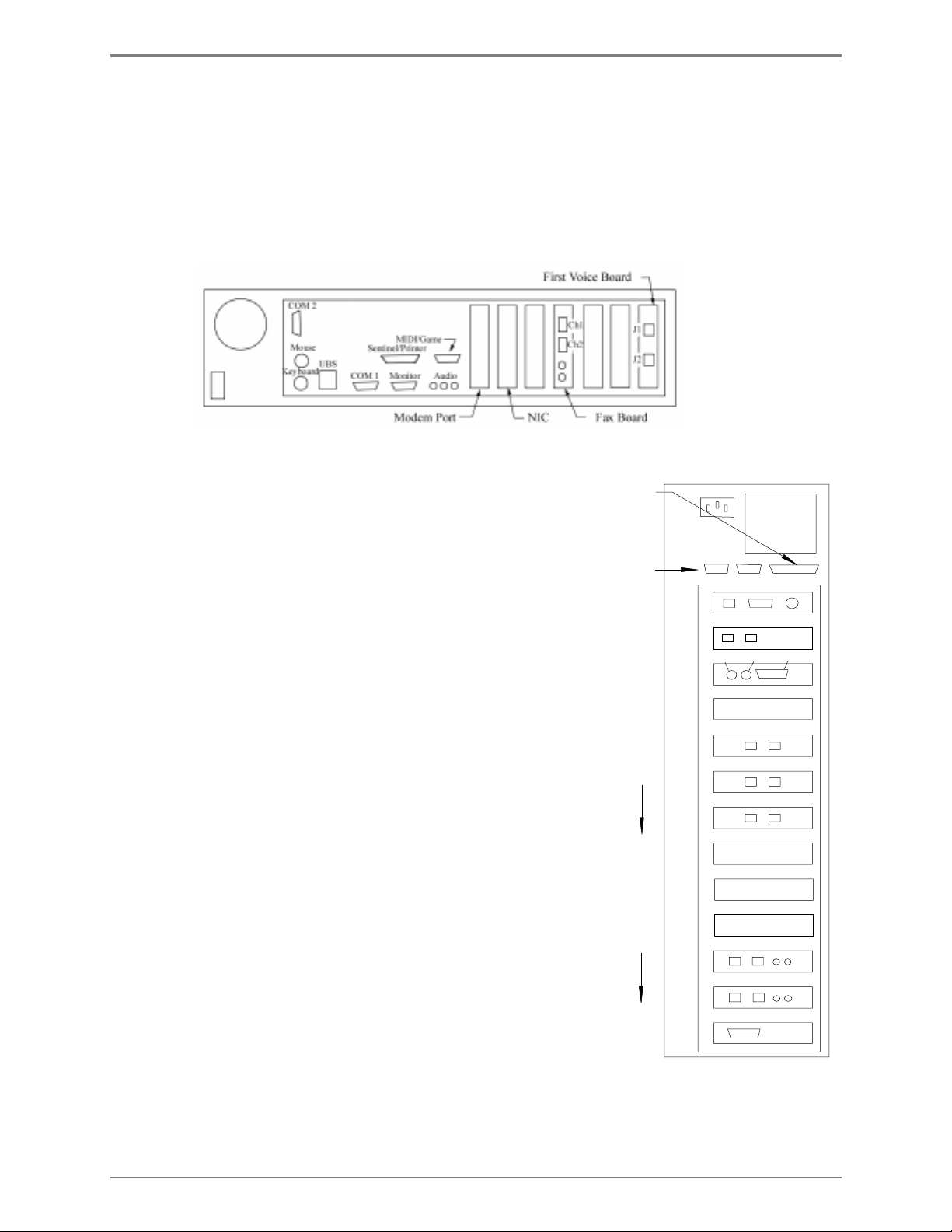
Desktop Platform Backplane Diagram
In the Desktop platform, voice boards are installed starting wit h t he right-hand slot, as viewed from t he back of the
PC. On each card, the upper jack is tied to the lowest numbered ports. The example diagram i ndicates the
connector designations for the DIALOG/4 board. W hen a singl e fax board is pr esent, it is installed in t he fourt h sl ot
from t he right , as viewed from the back of the PC. If two fax boards are present, the first will be in slot three and the
second will be in slot four. Fax ports are marked CH1 (upper) and CH2 (lower) on each board.
The types and number of cards install ed will depend on your system configuration. The Network Interface Card
(NIC) is opti onal.
Tower Platform Backplane Diagram
In the Tower platform, voice boards are installed starting with the 5th
slot from the top, as viewed from the back of the PC. On each card,
the left jack is tied to the lowest numbered ports. The example
diagram i ndicates the connector designations for the DIALOG/4
board.
When a single fax board is present, it is installed in the 12th sl ot
from t he top, as vi ewed from the back of the PC. If two fax boards
are present, the first will be in slot 12 and the second will be in slot
11. Fax ports are marked CH1 (left) and CH2 (r i ght) on each board.
The types and number of cards install ed will depend on your system
configurati on. The Network Interface Card (NIC) is optional.
Sentinel/Printer
Serial Ports
NIC
(when required)
Modem
CPU Slot
(Empty)
First Voice Board
(ascending
voice port #’s)
Additional
Voice Boards
(ascending
Fax port #’s)
Fax Board
(2nd slot filled)
Fax Board
(1st slot filled)
Pwr
AB
1
2
3
4
5
6
7
8
9
10
11
Ch1
12
KeyboardMouse Video
J1 J2
Ch2
Serial Board
(when required)
13
101-1773-001 OCTOBER 1999, ISSUE 12
Page 3

PC SPECIFICATION SHEET
Configuring the IBM V.90 PCI Data/Fax Modem for Octel 100
The IBM V. 90 PCI data/fax m odem is an inter nal modem support ed for use with Octel
100. This modem is preconfigured on Oct el 100 syst ems. This note provides instructions
for installing and conf igur ing the modem’s device driver in the event you have to re- ins tall
the operating system.
To install and configure the modem’s device driver:
1. If the messaging system running, shut it down.
2. Insert the disk labeled IBM V. 90 P CI Data/Fax Modem Dri ver Di sket te in the disk
drive.
3. Open a DOS window:
a. From the O S /2 desktop, double-c lick the OS/2 System icon. The OS /2 System
folder opens.
b. In the OS/2 Sy stem folder, double-c lick the Command Prompts icon. The
Command P rompts f older opens.
c. Double-click the DOS Wi ndow ic on. A DOS window opens.
d. From the C: \ prompt, type
e. Record the I/O Port and IRQ # that list on the screen.
f. At the C:\ prompt, type
The OS/2 desktop displays.
4. From the Command Prompts folder, double-click the OS/2 Window icon to open an
OS/2 window:
5. From the C: \ prompt, type
window displays the contents of the CONFIG . SYS file.
6. Loc ate the line that begins:
DEVICE=C:\OS2\BOOT\COM.SYS
7. M ak e sure that the rest of the line r eads as f ollows:
(1,3F8,4)(2,<
8. S elect Save from the File menu.
a. If this is the fi rst tim e y ou have saved the file, the Save Notific ation dial og box
displays.
b. Click Type. The Type dialog box displays.
c. Click Plain Text, then c lick Set . The file is sav ed.
9. Double-click the icon in the upper-left corner of the window to close t he editor. The
OS/2 window displays.
port address from step 14e
A:PMDMCFG
EXIT
E CONFIG.SYS
and press <ENTER> to c lose the DOS window.
and press <ENTER>.
and press <ENTER>. A n OS/2 editor
>,<
IRQ # f r om step 14e
>)(4,2F8,3)
10. Type
11. Shut down the PC:
101-1773-001 OCTOBER 1999, ISSUE 13
EXIT
a. S elect Shutdown f rom the LaunchPad. When y ou ar e pr ompted whether you
want to close all windows and active pr ogr ams, click OK.
b. When prompted to shut down or reboot, turn off power to the PC.
and press <ENTER> to exit t he OS/2 window.
Page 4

PC SPECIFICATION SHEET
Notes:
101-1773-001 OCTOBER 1999, ISSUE 14
 Loading...