

Page 1

Partner® Advanced
Communications Systems
Installation
518-456-152
Comcode 108407768
Issue 1
November 1997
Page 2

Copyright © 1997 Lucent Technologies Lucent Technologies 518-456-152
All Rights Reserved Comcode 108407768
Printed in U.S.A. Issue 1
November 1997
Notice
Every effort was made t o ensure that the information in this book was complete and accurate at the
time of printing. However, information is subject to change.
Federal Communications Commission (FCC) Interference Notice
This equipment has been t ested and found to comp ly wi th t he li m its of a Class A or Class B digital
device, pursuant to Part 15 of FCC rules. F or additional FCC inf ormati on, see the FCC Notice at the
beginning of the
PARTNER Advanced Communications System Programming and Use
guide.
Canadian Emissions Requirements
This digital apparatus does not exceed the Class A or Class B limits for radio noise emi ssions from
digital apparatus set out in the Radio Inte rference Regulat ions of the Industry Canada (IC). For
additional IC information, see the IC Noti fi cation and Repair Information at the beginning of the
PARTNER Advanced Communications System Programming and Use
Le present apparei l numerique n’emet pas de bruits radioelectriques depassant les limites
applicabl es aux appareils numeriques de la classe A ou de la classe B prescrites dans le Reglement
sur le brouillage radioelectrique edi cte par le ministere des Industrie Canada. Vous trouverez des
renseignemen ts complémitaires à la
and Use
manuel.
PARTNER Advanced Communications System Programming
guide.
Security
Toll fr aud, the unauthorized use of your telecommunicatio ns system by an unauthori zed party (for
example , persons other than your company’s emp loyees , agents, subcontractors, or persons working
on your company’s behalf) can result in substantial additional charges for your telecommunications
services. You are responsible for the security of your system. There may be a risk of toll fraud
associated with your telecommuni cations sytem. You are responsibl e for programm ing and
configuring your equipment to prevent unauthorized use. Your system manager should read all
documents provi de d with t his pr oduct t o full y under sta nd the f eat ures that c an intr oduce t he risk of toll
fraud and the steps that can be taken to reduce that ri sk. Lucent Technologies does not warrant that
this product is immune from or will prevent unauthorized use of common-carrier tel ecom m unication
services or facilitie s accessed through or connect ed to it. Lucent Technologies will not be responsible
for any char ges that re sult fr om such unauthori zed use . If you suspe ct you ar e being vict imiz ed b y toll
fraud and you need technical support or assist ance, call Lucent Technologies National Customer
Care Center at 1 800 628 2888.
T rademarks
Magic on Hold, MLS-34D, MLS-18D, MLS-12D, MLS-12, MLS-6, PARTNER, PARTNER MAIL,
PAR TNER MAIL VS, and SYSTIMAX are registered trademarks of Lucent Technologies. TransTalk is
a trademark of Lucent Technologies. Phillips is a registered trademark of Phillips Screw Company.
Warranty
Lucent Technologies provides a limited warranty for this product. See Appendix B of the
Advanced Communi cations System Progr am ming and Use
guide.
PARTNER
Ordering Information
The order numbe r for this book is 518-456-152. To order additional books, call 1 800 457 1235 in the
continental U.S. or 1 765 361-5353 outside the continental U.S . For information about ordering other
system reference materials, replacement parts, accessories, and other compatible equipment, see
"Product Ordering Information" in Appendix B of the
Programming and Use
guide.
PARTNER Advanced Communications System
Support Telephone Number
In the contin ental U.S., Lucent Technologies provides a toll -free customer hotl ine 24 hours a day.
Call the hotlin e at 1 800 628-2888 or your Lucent Technologies Authorized Dealer if you need
assistance when installing your system. Consultat ion charges may apply.
Outside the cont inental U.S., contact your Lucent Technologies Representative or local
Authorized Dealer
Page 3

Contents
Contents
■ Overview 3
■ An Example System Setup 4
■ Required Parts 5
■ Installation Guidelines 7
Telephones and Devices 7
Combination Extensions 8
■ Installation Procedures 10
Wall-Mounting a Standalone
PARTNER ACS Proces sor Module 10
Wall-Mounting a 2-Slot Carrier and Modules 11
Wall-Mounting a 5-Slot Carrier and Modules 14
Inserting Batteries in the PARTNER ACS
Processor Module 16
Initializing the System 18
Connecting Lines and Extensions 20
Assembling System Phones 22
Connecting and Testing Telephones 25
Connecting Contact Closure,
Call Reporting (SMDR),
Paging, and Music-On-Hold Devices 26
Connecting a PARTNER-CA48
Intercom Autodialer 28
■ Equipment Upgrades 29
Adding New Modules 29
Replacing System Modules 31
i
Page 4

Important Safety Instructions
The following list provides basic safety precautions that should always be followed when
using your telephone equipm ent:
1. Read and understand all instructions.
2. Follow all warnings and instructions marked on the product.
3. Unplug all telephone connections before cleaning. DO NOT use liquid cleaners or aerosol cleaners.
Use a damp cloth for cleaning.
4. This product should be serviced by (or taken to) a qualified repair center when service or repair
work is required.
5. DO NOT use this product near water, for example, in a wet basement location.
6. DO NOT place this product on an unstable cart, stand, or table.
7. Never push objects of any kind into slots or openings as they may touch dangerous voltage points
or short out parts that could result in a risk of fire or electric shock. Never spill liquid of any kind on
the product.
8. DO NOT use the telephone to report a gas leak in the vicinity of the leak.
9. The product is pr ovided with a three-wire grounding type plug. This is a safet y feature. DO NOT
defeat the safety purpose of the grounding type plug. DO NOT staple or otherwise at tach the power
supply cord to building surfaces.
!
CAUTION:
DO NOT block or cover the ventilation slots or openings. They prevent the product
from overheating. DO NOT place the product in a separate enclosure unless proper
ventilation is provided. DO NOT place the product flat on a surface. The control unit
must be wall-mounted.
Page 5

Additional Safety Instruct ions f o r
Installation Personnel
1. DO NOT install telephone wiring during a lightning storm.
2. DO NOT install telephone jacks in a wet location unless the jack is specifically designed for wet
locations.
3. Never touch uninsulated telephone wires or term inals, unless the telep hone li ne has been
disconnected at the netw ork interface.
4. Use caution when installing or modifyi ng telephone lines.
5. The control unit m ust be securely wall mounted.
6. supply cord to building surfaces.
!
CAUTION:
If any wiring from the extension jacks leaves the building premises, you must install
Lucent Technologies™ IROB protectors (see “Requirements for Out-of-Building
Extensions” on page 36.)
!
CAUTION:
Use only Lucent Technologies-manufactured PARTNER modules in the PARTNER
Advanced Communications System.
!
CAUTION:
Environmental and electrical conditions must meet the requirements as listed on
page 36.
SAVE THESE INSTRUCTIONS
Page 6

Installation
Overview
This guide explains how to install the PARTNER® Advanced Communications System (ACS)
Releases 1.0, 1.1, 2.0 or later. The information applies to all releases unless otherwise
specified.
This guide begins with an example system setup, then shows the components you need to
install the system and gives general guidelines to consider before installation. Next, it
provides step-by-step instructions for connecting and testing the components for initial
installation and upgrades. Finally, it lists important system specifications. Make sure that your
installation meets all electrical and environmental requirements.
If your company already has modular jacks for all outside lines and extensions, you may be
able to use the existing wiring to install the system hardware and connect telephones to the
system yourself . To have a Lucent Technologies service technician install and customize your
system or change existing wiring, call 1 800 247-7000 (in the continental U.S. only) or call
your Lucent Technologies Representative or local Authorized Dealer.
After installation, refer to the
and Use
guide for programming instructions.
PA RTNER Advanced Communications System Programming
Overview 3
Page 7
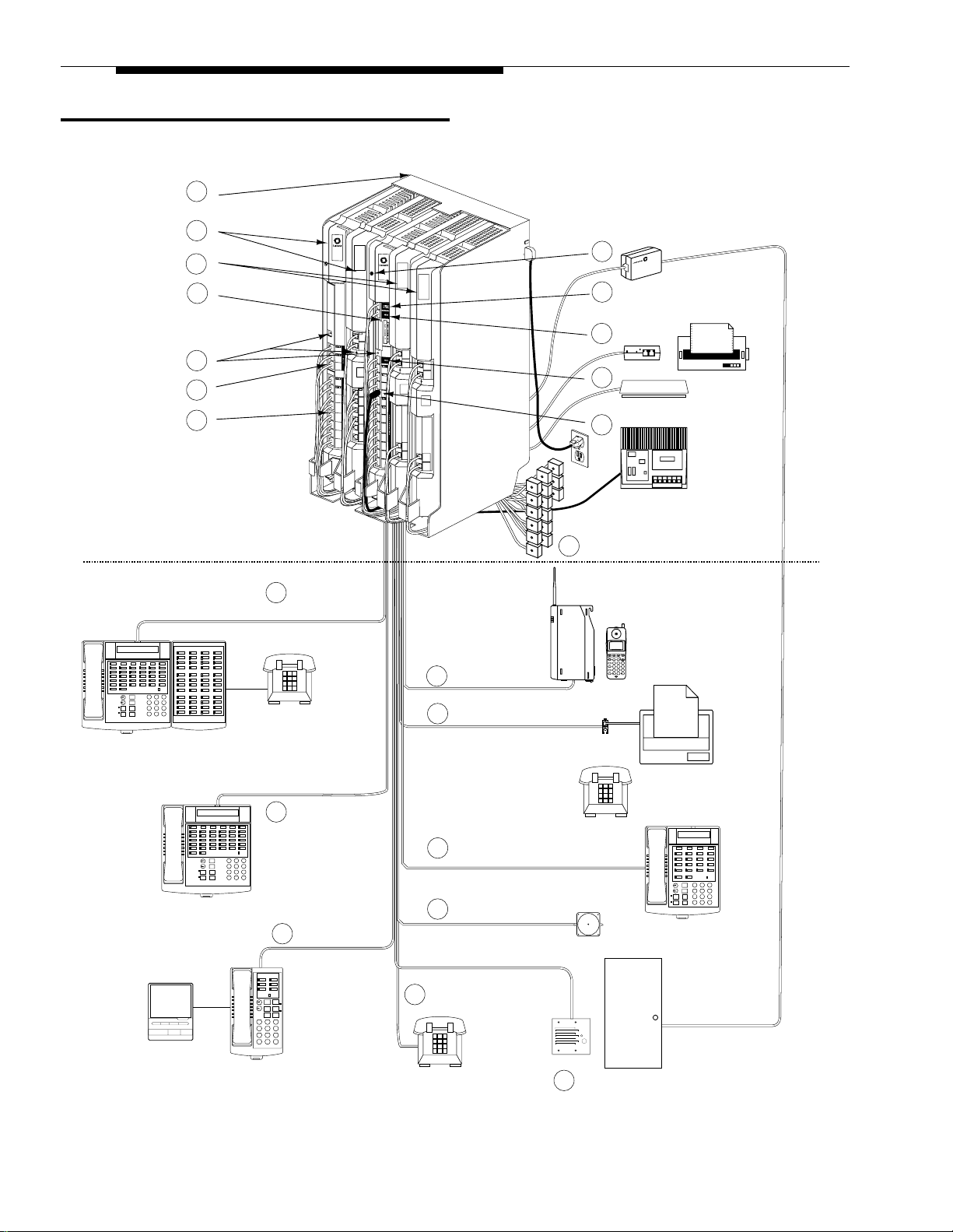
An Example System Setup
CONTROL UNIT
1
2
3
4
10
8
11
PARTNER
3000
PARTNER
PARTNER
3000
PARTNER
PARTNER
PFT
L
I
7
N
E
S
8
4
5
6
18
19
20
21
22
23
24
25
ACS
Proc.
L
9
I
N
E
L
10
S
13
206
1
MODULE
R1.0
2
3
PFT
26
E
27
X
10
T
E
11
28
N
S
12
29
I
O
N
13
30
S
14
31
15
16
17
I
N
E
14
S
400
MODULE
R1.0
400
MODULE
R1.0
11
12
15
16
5
PARTNER 3000
Contact Closure Adjunct
5
a
6
7
9
12
EXTENSIONS
Ext.
Intercom
Message
Intercom
ABC2DEF
Feature
+
31
–
JKL5MNO
GHI
Conf
6
4
TUV8WXYZ
PQRS
Mic
Transfr
HFAI
9
7
Hold
Spkr
#
0
*
13
Extension 10
POWER
RADIO
PASS
212555 1212
MSG
ON
78
65
234
1
AB
CD
Redial
Mute
On/Off
ABC
DEF
Feat/P
12
3
GHI
JKL
MNO
Conf
5
6
4
WXYZ
PQRS
TUV
Trans
97
8
OPER
0
Hold
21
Extension 18
20
Extension 17
Extension 11
14
Ext.
Intercom
Message
Intercom
ABC2DEF
Feature
+
31
–
JKL5MNO
GHI
Conf
6
4
TUV8WXYZ
PQRS
Mic
Transfr
HFAI
9
7
Hold
Spkr
#
0
*
15
Extension 12
Intercom Intercom
Message
Ext.
Feature
Spkr
+
–
Mic
Conf
HFAI
Transfr
Hold
ABC2DEF
31
JKL5MNO
GHI
6
4
TUV8WXYZ
PQRS
9
7
#
0
*
19
Extension 16
Extension 15
18
16
Extension 13
TransTalk
Message
Ext.
Intercom
Intercom
ABC2DEF
Feature
+
31
–
JKL5MNO
GHI
Conf
6
4
TUV8WXYZ
PQRS
Mic
Transfr
HFAI
9
7
Hold
Spkr
#
0
*
PUSH
4 An Example System Setup
Extension 14
17
Page 8
Required Parts
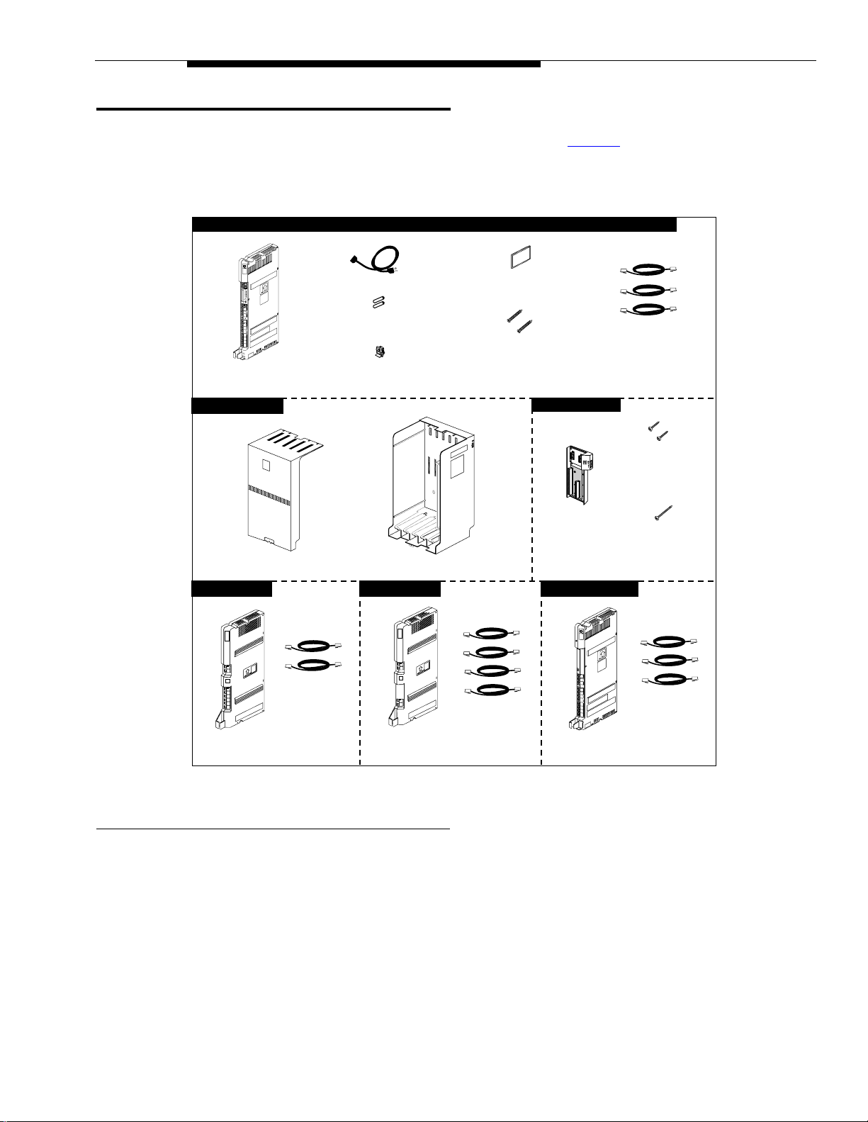
PARTNER Advanced Communications System Processor Module
You may have multiple system component packages; Figure 1 shows the package contents.
Check your packages to be sure you have the parts shown here (if not, call for suppor t as
instructed on the inside front cover of this guide).
PARTNER
3000
AC Power Cord
Backup/Restore
PC Card*
ACS Processor
Module
5-Slot Carrier
PARTNER Plus
206 Module
PARTNER
PFT
L
I
N
E
S
206
MODULE
PFT
E
X
T
E
N
S
I
O
N
S
206
Module
Cover
7-foot
Line Cords
AAA Alkaline
Batteries
#8-15 x 11/2"
®
Battery Door
Cover
Phillips
Metal Screws
Sheet
2-Slot Carrier
2-Slot
Carrier
5-Slot Carrier
400 Module 308EC Module
PARTNER
PFT
L
I
N
E
S
400
MODULE
R1.0
PFT
L
I
N
E
S
7-foot
Line Cords
400
Module
PARTNER
3000
308EC
Module
7-foot
Line Cords
3
#4 x
/4"
Panhead
Sheet Metal
Screws
#8-15 x 31/2"
Phillips
Panhead
Screw
7-foot
Line Cords
Figure 1. Required Parts
*
The Backup/Restore PC Card is included with the PARTNER ACS processor module when the system is purchased in the
United States or Canada. Other wise, it can be purchas ed separately.
For a 5-Slot carrier, you will need to obtain four #12 screws of the appropriate type for the
wall and weight of the control unit (a control unit with four 206 modules and a processor
module weighs approximately 31 pounds or 14 kilograms). The weight of other configurations
may vary sl ightly.
In addition, if you need modular telephone cords to connect the extension jacks in the control
unit to the modular connecting blocks for extensions in the equipment room, short telephone
cords or wall plates to wall mount PARTNER-model phones, or a 355A/355AF adapter and
D8W telephone cord to connect a call reporting device, order them before installation. Refer
Required Parts 5
Page 9

to "Product Ordering Information" in Appendix B of the
Communications System Programming and Use
The P AR TNER ACS processor module and the 206EC, 308EC, and 400EC modules support
the Caller ID feature. These modules are required to provide Caller ID information on system
display phones. You must subscribe to Caller ID service from your local telephone company
(if it is available), and connect any lines associated with this service to the line jacks on the
processor module, the 206EC module, the 308EC module, or the 400EC module. Hereafter,
references in this guide to 206 modules include 206E, 206EC, and all 206 modules used with
previous releases of the product. Similarly, references to 400 modules include 400E, 400EC,
and all 400 modules used with previous releases of the product.
NOTE:
A system display phone is required for programming at extension 10 and/or 11. If
you have any 34-button phones in the system, you must use a 34-button display
phone to program since an 18-button phone cannot be used to program a 34-button
phone. Also, if your system has both PARTNER-model and MLS-model phones, it is
recommended that you use a P AR T NER-model display phone at the programming
extension.
PA RTNER Advanced
guide for ordering instructions.
6 Required Parts
Page 10

Instal la tion Guide l ines
Telephones and Devices
You can connect the following telephones and devices to the system:
■ PARTNER-model, MLS-model, MDC 9000, and TransTalk™ 9000-se ries System Pho nes.
System phones require at least two-pair wiring and are compatible with Lucent Technologies
4-pair SYSTIMAX
■ Call Assistant Intercom Autodialers with Busy Indication (PARTNER-CA48 for
PAR TNER-model phones or MLS - C A24 for MLS-model phone s). You can connect an
Intercom Autodialer to the system phones at extension 10 and 11. The Intercom Autodialer
connects to the system phone using an adapter that is shipped with the autodialer.
■ Industry-Standard Devices. Industry-standard devices (including standard phones) require
one-pair mounting cords; Lucent Technologies D2R mounting cords are recommended.
— Standard Phones. Connect standard touch-tone or rotary dial phones to the system for:
— Power Failure Operation. During a power failure, system phones will not work because
they require power to operate. However, if you connect standard phones to the first two
extensions on the P ART NER ACS processor module, users can place and answer outside
calls on the first two lines. If you connect a standard phone to the first extension on each
206 module, or the first two extensions on each 308EC module, users can place and
answer outside calls on any of these lines. You can connect a standard phone either alone
or combined with a system phone. For more information, see ‘‘
on page -8.
®
wiring.
Combination Extensions’’
— Hotlines. A hotline extension should be connected to a standard phone, rather than a
system telephone, but can ring any type of phone. An internal hotline phone can also be
set up to ring the paging system, so announcements can be made over the loudspeaker.
Do not connect a hotline phone to extension 10, 11, or the first two extensions of any 206
or 308EC module, to keep these extensions available for power failure use.
For message waiting capability, you must connect standard phones with LED-compatible
message-waiting lights to a PARTNER ACS processor module, 308EC modules, or Release 3.1 (R3.1)
or later 206 modules. This message- waiting capability does not work with standard phones with
neon-type message-waiting lights.
— Auxiliary E qui pm ent. There are a variety of ways to set up fax machines, modems, and
answering machi nes to work with the syst em. See Chapter 4 in the
Communications System Programming and Use
guide for advice on using this equipment.
To connect a telephone and a standard device on the same extension, see ‘‘
PARTNER Advanced
Combination
Extensions’’ on page -8.
■ Doorphones. You can connect up to two doorphones to the system. Do not connect doorphones
to extension 10, 11, or the first two extensions of any 206 or 308EC module.
■ Contact Closures. You can connect up to two Contact Closure devices such as door locks to the
Contact Closure Adjunct so that the devices can be activated from an extension on a user s desk.
■ Voice Messaging Systems. The system supports the following voice messaging systems:
®
— The PARTNER MAIL VS
System. This device, which physically resembles a 206
module, resides in the control unit.
®
— The PARTNER MAIL
System. This device connects to the system through extension
jacks. Do not connect PARTNER MAIL to extension 10, 11, or the first two extensions of
any 206 or 308EC module to keep these extensions available for power failure use.
Installation Guidelines 7
Page 11
— The PARTNER Voice Messaging PC Card. For more information on using this voice
messaging system, see the
Programming and Use Guide
■ Call Reporting Devices. You can connect either a serial printer or a call accounting device, such
as Lucent Technologies Call Accounting Terminal, to the SMDR jack on the processor module to
record and/or analyze call activity.
■ In-Range Out-of-B uilding Prot ectors. Installing phones or other standard devices (such as a
doorphone) in a location other than the building where the control unit is installed requires Lucent
Technologies In-Range Out-of-Building (IROB) protectors, to prevent damage from lightning.
(IROBs must be installed by a qualified technician.)
Combi na tion Ex te nsions
You can connect a standard device (such as a standard phone or an answering machine) on an
extension by itself, or so that it shares an extension with another piece of equipment (either another
standard device or a system phone). An extension with two devices connected to it is called a
combination extension
may want to turn off the standard phone s ringer during normal use.)
You canno t install two system phones on the same extension, and the combined REN (Ringer
Equivalence Number) of two devices on one extension cannot exceed 2.0. (The REN for a system
phone is 0.0.)
NOTE:
The Call Assistant Intercom Autodialer is not regarded as a standard device. This means you can
connect a standard device to a system phone that also has an Intercom Autodialer installed.
PA RTNER Voice Messaging PC Card Installation,
.
. (If you combine a standard phone and a system phone on one extension, you
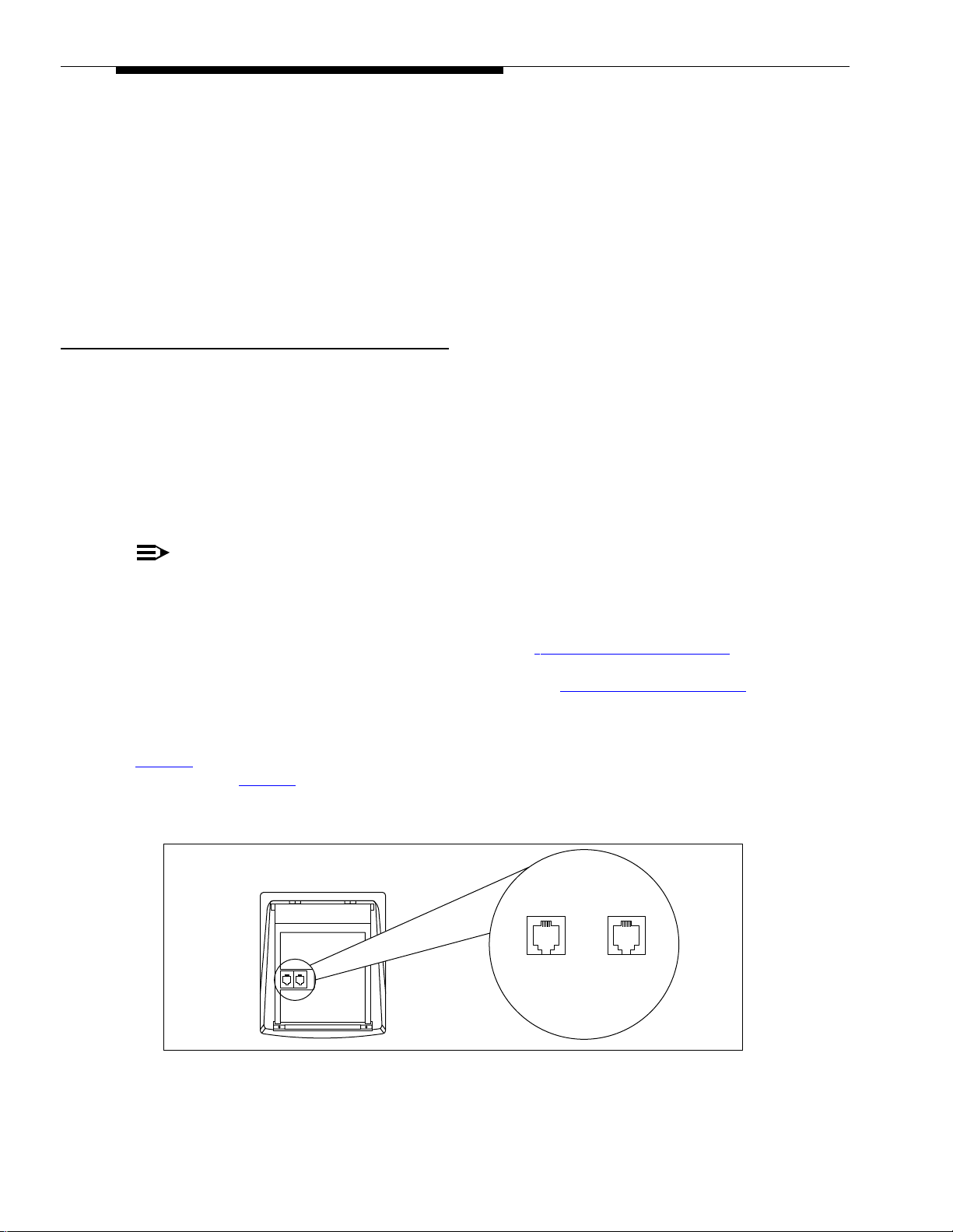
PARTNER-model system phones have a built-in auxiliary jack so you can connect a standard device
directly to the phone without using a bridging adapter see ‘‘
phone does not have a built-in auxiliary jack or if you want to connect two standard devices together, you
must use a Lucent Technologies 267F2 Bridging Adapte r see ‘‘
Using A Direct Connection
Figure 2 shows how to connect a standard device directly to a system phone, using the phone s built-in
auxiliary jack. (Figure 2
differ.)
Figur e 2. Combi na tion Ex tension Using Direc t Connection
Using A Direct Connection’’, below. If your
Using a Bridging Adapter’’, below.
is for illustration purposes only; the placement of the jacks on your phone may
System Phone
Plug line into
jack labeled LINE
Plug standard device
into jack labeled
AUX
8 Installation Guidelines
Page 12
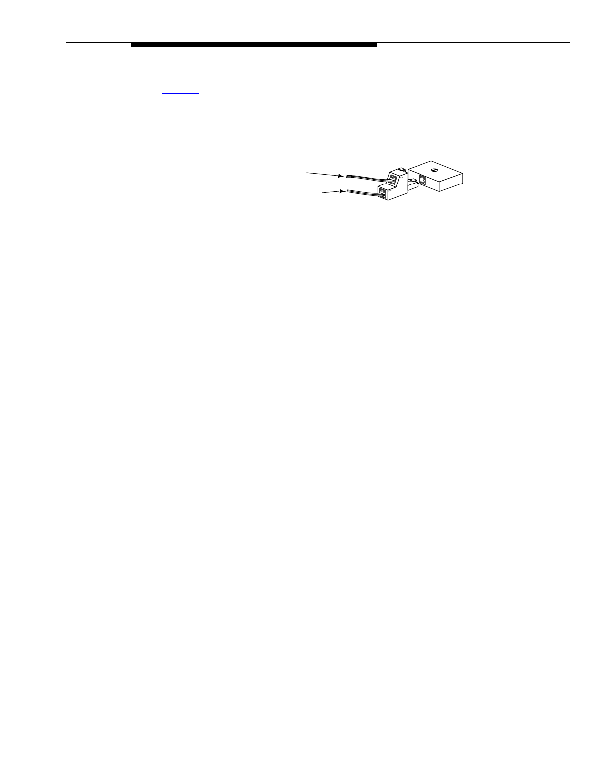
Using a Bridging Adapter
Figure 3 shows how to connect a system phone and a standard device or two standard
devices using a (separately orderable) Lucent Technologies 267F2 Bri dging Adapter.
Lucent Technologies
267F2
Adapter
Standard Device Only
System Phone or Standard Device
Figure 3. Combination Extension Using Bridging Adapter
Wall Jack
Installation Guidelines 9
Page 13
Installation Procedures
Before installing the system, be sure you read the safety instructions on page ii.
The PA RTNER Advanced Communications System can be installed in one of three configurations:
■ standalone PARTNER ACS processor module.
■ 2-Slot carrier, which can hold up to two modules.
■ 5-Slot carrier, which can hold up to five modules and includes a cover.
The standalone processor module or a carrier and its modules are referred to as the control unit. The control unit
must always be wall-mounted. See the following sections for wall-mounting instructions.
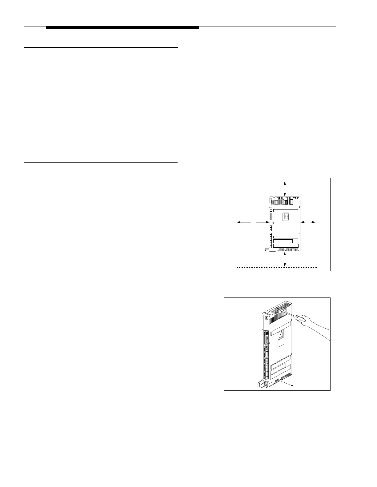
Wall-Mounting a Standalone P ARTNER ACS Processor Module
Install the PARTNER ACS processor module within 5 feet (1.5 meters)
of a properly grounded wall outlet (not controlled by a switch) and the
network interface jacks.
1' (0.3 m)
1 A) Hold the PARTNER ACS processor module
against the wall with the line and extension jacks
facing left.
2'
(0.6 m)
1'
(0.3 m)
B) Leave at least 1 foot (0.3 meters) clearance at
the top, front, and right side, and at least 2 feet
(0.6 meter) at the bottom and left side. This
allows you to access the jacks or expand the
system with another module, and ensures
adequate ventilation.
2 A) Inser t one of the #8 sheet metal screws into the
screw hole at the top of the module.
B) If you are not installing a second module, insert
the other #8 sheet metal screw into the screw
hole at the bottom of the module. If you are
installing a second module, do not screw in the
bottom screw at this time.
C) Tighten the screw(s) until the mounting tracks
are snug against the wall.
(1 cm) gap between the wall and the rest of the
module
. Do not overtighten the screw(s) the
module will warp and fail to operate.
There must be a 3/8”
PARTNER
3000
1' (0.3 m)
10 Installation Procedures
Page 14
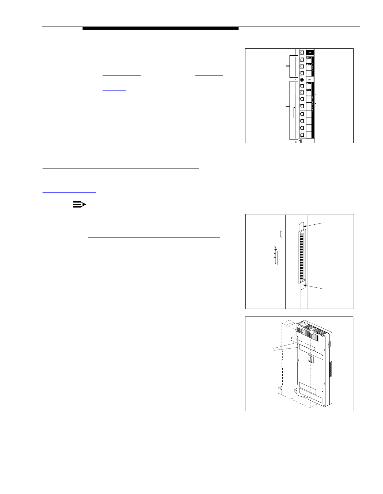
3 A) Label the line and extension jacks as shown.
B) If you are installing a two-module system,
continue with ‘‘
and Modules’’; otherwise, skip to ‘‘Inserting
Batteries in the PARTNER ACS Processor
Module’’.
Wall-Mounting a 2-Slot Carrier
Lines
Extensions
1
2
3
10
11
12
13
14
15
16
17
Wall-Mounting a 2-Slot Carrier and Modules
To wall-mount a 2-Slot Carrier, first follow the instructions in ‘‘Wall-Mounting a Standalone PARTNER ACS
Processor Module’’.
NOTE:
To add a 308EC module to a PARTNER ACS module,
the ACS processor module must already be mounted
on th e wa l l. If it is not, r e fer to ‘‘
Standalone PARTNER ACS Processor Module’’ on
the previous page for instructions. Before starting,
disconnect the power cord from the power jack on the
carrier. Then follow the instructions below.
Wall-Mounting a
Tab
You can install a 206, 308EC, 400, or PARTNER MAIL VS module as
the second module, using the following steps:
1 Remove the clear, plastic protector from the connector
on the right side of the new 308EC module by
grasping the tabs on the ends of the protector and
lifting. If you are upgrading from a standalone system,
also remove the protector from the wall-mounted ACS
processor module.
2 A) Remove the #8 sheet metal screw from the
bottom of the wall-mounted module or modules.
B) If you are upgrading an existing single module
system, skip to Step 4B .
3 If you are replacing the second module in a two-slot
carrier, remove the two #4 screws holding the carrier
in place, and gently pull the carrier off the modules.
Tab
Mounting
Tracks
Installation Procedures 11
Page 15
4 A) S lide the second mo dule off the PARTNER ACS
module and put it aside.
B) S lide the 308EC mo dule onto the PARTNER
ACS module, making sure the mounting tracks
interlock, as shown in the side view.
!
CAUTION:
Do not force the module. If it does not insert eas ily,
remove the module, clear any obstruction, and
reinse rt it.
5 A) Attach the 2-Slot carrier to the top right side of
the two modules.
B) Fasten the carrier to the modules using the two
#4 screws included with the carrier.
6 Inser t the 3-1/2” #8 screw into the bottom of the
modules. Tighten it until the mounting tracks of the
PARTNER ACS module are flush against the wall with
a 3/8” (1cm.) gap between the wall and the rest of the
PA RTNER ACS module. Do not overtighten the
modules will warp.
PARTNER
206
MODULE
7 A) Label the lines and extension jacks as shown.
B) Connect modular phone cords to the extension
jacks, starting at the top extension jack on the
PA RTNER ACS processor module.
C) Route each cord through the hook on the front of
its module.
D) Connect the free end of each phone cord to the
modular wall jacks for system extensions.
8 A) Attach one end of a # 12 AWG or # 14 AWG
solid copper wire to the grounding screw on the
primary proc essor module. Note that the length
of the wire must not exceed 35 feet (7.6 meters).
B) Route the wire through the hook on the front of
the module.
C) Attach the other end of the wire to the approved
earth ground, such as building steel or cold
water pipe.
ACS
Processor
Module
Lines
Extensions
PFT
L
I
N
E
S
E
X
T
E
N
S
I
O
N
S
206
Module
Lines
Extensions
12 Installation Procedures
Page 16

9 Press the power cord firmly into the power jack on the
carrier. Plug the other end of the power cord into a
properly grounded three-prong wall outlet not
controlled by a switch.
10 Check the green lights on the fronts of the modules. If
a single light is out, power down the carrier, reseat the
module, then power up the carrier. If both green lights
are out, power down the carrier, reseat both modules,
then power up the carrier. If the lights are out, in the
continental U.S. call the hotline at 1 800-628-2888.
Outside the continental U.S., contact your Lucent
Technologies Representative or local Authorized
Dealer.
Installation Procedures 13
Page 17

Wall-Mounting a 5-Slo t C a rrier and M od ule s
Install the 5-Slot carrier within 5 f eet (1. 5 met ers) of a properly grounded wal l outlet (not controlled by a switch) and
the network interface jacks. In addition, when you mount the carrier on the wall, leave at least 1 foot (0.3 meter) of
clearance at the top and sides, and two feet (0.6 meter) at the front and bottom to ensure proper ventilation.
NOTE:
The location of each module within the carrier is important; place them as instructed in the following
procedure.
1 A) Hold the 5-slot carrier against the wall.
B) Using the four screw keyholes in the carrier as a
template, mark screw locations on the wall.
C) If you re mounting the carrier on plywood, start
four #12 screws supplied with the carrier leaving
the screw heads extending approximately 1/4
(.64 cm) from the wall. If you are mounting on
drywall, use wall anchors, which must be
purchased.
2 Before installing any modules, make sure the clear,
plastic protector has been removed from the
connector area on the rear of each module. T o remove
the protector, grasp the tabs on the ends of the
protector and lift.
NOTE:
308EC and 206 modules must be to the left of any 200
and 400 modules.
Carrier
Tab
Tab
1
"
4
3 A) Verify that the P AR TNER ACS processor module
is in the center slot of the carrier. In the other
slots, from left to right, first install the 308EC or
206 modules followed by the 400 or 200
modules.
B) Align the module carefully in the appropriate slot,
and push slowly but firmly in the center of the
module until the connectors on the module lock
into place, and the module is attached to the rear
of the carrier.
!
CAUTION:
Do not force the module. If it does not insert eas ily,
remove the module, clear any obstruction, and
reinse rt it.
14 Installation Procedures
PARTNER
3000
Page 18

4 A) Label the line and extension jacks.
B) Connect line and telephone cords to the
appropriate jacks on the new module.
C) Route each cord through the hook on the front of
its module.
D) Connect the free end of each line cord to the
appropriate network interface jack.
E) Connect the free end of each telephone cord to
the modular connecting blocks for system
extensions.
F) Gather the line and extension cords hanging
below the hook and twist tie or wire wrap them.
G) Place the bundle of wires in the indentation on
the bottom of the carrier.
5 A) Attach one end of a # 12 AWG or # 14 AWG
solid copper wire to the grounding screw on the
primary proce ssor module. Note that the length
of the wire must not exceed 35 feet (7.6 meters).
B) Route the wire through the hook on the front of
the module.
PFT
L
I
N
E
S
206
MODULE
PFT
E
X
T
E
N
S
I
O
N
S
Grounding
Screw
PARTNER
3000
PFT
L
I
N
E
S
206
MODULE
PFT
E
X
T
E
N
S
I
O
N
S
PARTNER
3000
C) Attach the other end of the wire to the approved
earth ground, such as building steel or cold
water pipe.
6 A) Plug the power cord into a properly grounded
three-prong wall outlet not controlled by a switch.
B) Power up the control unit by moving the On/Off
switch to the "On" position (“—”).
7 A) Check the green lights on the fronts of the
modules.
B) I f a single light is out, power down the carrier,
reseat the module, then power up the carrier. If
multiple lights are out, power down the carrier,
reseat the leftmost module that has a light out,
then power up the carrier.
C) If the lights are still out, in the continental U.S.
call the hotline at 1 800-628-2888. Outside the
continental U.S., contact your Lucent
Technologies Representative or local Authorized
Dealer.
8 Continue with Inserting Batteries in the PA RTNER
ACS Processor Module.
Installation Procedures 15
Page 19

Inserting Batteries in the PARTNER ACS Processor Module
The PA RTNER ACS processor module uses two user-replaceable, AAA-size standard alkaline batteries to guard
against the loss of system programming in case of a power failure. These batteries will retain the system
programming for 45 days to 6 months, depending on the freshness of the batteries. It is recommended that you
replace the batteries with fresh ones every year.
!
CAUTION:
If this is a new installation, you need to install batteries. Batteries and battery cover may be packed
in a separate box. If you are replacing batteries, the old batteries must be removed with the power
on or the system s memory will be lost.
Use the following procedure to replace the batteries:
1 Locate the battery compartment at the bottom of the
PA RTNER ACS processor module, below the
extension jacks.
Battery
Compartment
2 Push gently on the battery icon (the locking latch) and
slide the battery icon up to cover the plus icon, which
unlocks the battery assembly.
Locking
Latch
Locked
Position
Unlocked
Position
16 Installation Procedures
Page 20

3 Remove the battery assembly by gently pulling the tab
at the bottom of the battery compar t me nt cover.
4 Inser t two new AAA-size standard alkaline batteries
into the metal battery clips by pushing them straight in,
placing the negative (–) end of one battery into the
bottom clip, and the positive (+) end of the other
battery into the top clip.
Tab
Push to
insert
5 With the locking latch in the unlocked position (battery
icon and "minus" icon visible), slide the battery
assembly into the processor module along the battery
guides on the inside of the battery compartment.
6 Make sure the battery assembly is pushed in far
enough that the edges of the assembly slip behind the
plastic housing of the processor module.
7 Pressing lightly on the battery icon on the front of the
battery assembly, slide the locking latch downward to
secure the assembly in place. The "plus" icon and the
battery icon should now be visible on the front of the
battery assembly. This is the locked position.
Tab
Unlocked
Position
Locking Latch
Locked
Position
Installation Procedures 17
Page 21

Initializing the System
NOTE:
The system must be powered down before you insert or rem ove a PC Card.
The Backup/Restore, Automatic System Answer/Direct Extension Dial, PA RTNER MAIL Basics and software
upgrade features of the system all require the use of a PC card. If you plan to use any of these features, insert the
appropriate PC Card in a PC Card Slot before applying to the system. See ‘‘
in this guide.
Inserting or Removing a PC Card’’ later
Before you can use PARTNER MAIL
1.1 or later. PARTNER MAIL
Basics
Basics
, the PARTNER ACS must be upgraded from Release 1.0 to Release
does not work with ACS Release 1.0.
To apply the PA RTNER ACS Release 1.1 or Release 2.0 or later software upgrade, use the following
procedure:
1 Insert the PC Card in the PC Card Slot befo re
powering up the system for the first time.
2 Power up the system as described in the following
procedure. While the system upgrades, the bicolor
(red/green) power LED on the processor flashes green
and red alternately. When the upgrade has finished (in
about 20 seconds), the power LED becomes steady
green.
Main Circuit Breaker or
On/Off Switch
PARTNER
3000
PFT
L
I
N
PFT
E
L
S
I
N
E
S
PFT
L
I
N
PFT
E
L
S
I
206
MODULE
R3.0
PFT
E
X
T
E
N
S
I
O
N
S
N
E
S
206
MODULE
R3.0
PFT
400
E
MODULE
R3.0
X
T
PFT
400
MODULE
E
R3.0
N
PFT
S
E
I
X
O
T
N
E
E
S
X
N
T
S
E
I
N
O
S
N
I
S
O
N
S
Power
Jack
3 Power down the system.
4 Remove and discard the one-time-use software
upgrade card.
5 Repower the system.
To power up the system, use the following procedure:
1 A) If you have a Standalone or a 2-Slot carrier
configuration, skip to Step 1B. If you have a
5-Slot carrier, move the carrier s On/Off s witch t o
the "Off" position ("O").
B) P ress the power cord firmly into the power jack
on the carrier or Standalone PA RTNER ACS
processor module until it locks into place. (See
the illustrations on this page for the location of
the power jack for each type of configuration.)
C) Plug the other end of the power cord into a
properly grounded three-prong wall outlet not
controlled by a switch.
18 Installation Procedures
Page 22

D) If you have a 5-Slot carrier, power up the control
unit by moving the On/Off switch to the "On"
position.
2 Check all green lights on the fronts of the modules. If
all the lights are lit, continue with ‘‘
and Extensions’’; otherwise:
Connecting Lines
If a single light is out,
A)
power down the control
unit, reseat the module, then power up the
control unit.
If multiple lights are out,
power down the control
unit, reseat the leftmost module that has a light
out, then power up the control unit.
If the lights are still out,
B)
call for support as
instructed on the inside front cover of this guide.
Lights
PFT
PFT
L
I
N
E
S
L
I
N
E
S
Installation Procedures 19
Page 23

Connecting Lines and Extensions
1
2
3
10
11
12
14
15
16
17
13
10
11
12
14
15
16
17
13
-134
If extensions are not wired to any modular jacks, call a qualified service
technician.
1 A ) Test for dial tone at the network interface jacks
before connecting outside lines to the control
unit. For the test, connect a standard phone to
the first network interface jack.
B) Lift the handset and listen for dial tone. (If there i s
no dial tone, contact your local telephone
company before continuing.)
C) Repeat for each network interface jack.
2 A) Connect line cords to the line jacks on the ACS
processor module, and the 206, and 400
modules. Start at the top with the line jacks on
the processor module, and then move to the
leftmost 206 or 308EC module. Fill each module
before moving to the next module to the right.
B) Route each cord through the hook on the front of
the module.
Network
Interface
Jacks
555-1343
555-1344
555-1345
555-1346
3 Connect the free end of each line cord to the
appropriate network interface jack.
20 Installation Procedures
555
555-1347
555-1348
555-1349
Page 24

4 A) Test the lines—plug a system phone into
extension jack 10. Press the line buttons for each
outside line and listen for dial tone.
B) Repeat for the first extension on each module.
5 A) Connect modular telephone cords to the
extension jacks, starting at the top extension jack
on the PARTNER ACS processor module. When
that module is full, move to the leftmost 206 or
308EC module. Fill each module before moving
on to the next module to the right
B) Route each cord through the hook on the front of
the module.
C) Connect the free end of each modular telephone
cord to the modular wall jacks for system
extensions.
PFT
PFT
L
L
I
I
6
4
N
N
E
E
S
S
7
5
PFT
18
E
19
X
T
E
Message
Ext.
Intercom
Intercom
ABC2DEF
Feature
+
31
–
JKL5MNO
GHI
Conf
6
4
TUV8WXYZ
PQRS
Mic
Transfr
HFAI
9
7
Hold
Spkr
#
0
*
20
N
S
I
21
O
N
22
S
23
1
2
3
10
11
PFT
12
24
E
25
X
13
T
E
26
N
14
S
I
27
15
O
N
28
S
16
29
17
D) Dress the wires. Gather the line and extension
cords hanging below the hooks of the first two
modules and twist tie or wire wrap them. Repeat
for the remaining cords. For the 5-Slot carrier,
place each bundle of wires in the indentations
cut out of the bottom edge of the carrier.
6 If you have a 5-Slot carrier configuration, install the
cover as follows:
A) Make sure all modules are seated properly . The
cover will not fit if the modules are not seated
properly .
B) To cover the modules, grasp the upper edges of
the cover and hold it squarely over the control
unit. It is important to install the cover to keep the
modules dust-free and the system working
efficiently.
C) Place the cover over the modules and make sure
it fits firmly in place.
D) Insert the #6 screw into the tab on the lower front
of the cover. Tighten the screw.
Screw
PARTNER Plus
PFT
L
I
1
N
PFT
E
L
S
2
I
3
N
PFT
E
L
PAGE
S
4
I
N
E
PFT
L
S
I
5
206
MODULE
N
E
S
6
206
MODULE
PFT
PROCESSOR
MODULE
10
PFT
E
206
206
MODULE
MODULE
11
X
16
T
E
E
12
17
X
N
T
S
VOL
E
I
13
18
N
O
S
N
14
I
19
S
MUSIC
O
ON
N
HOLD
15
20
S
21
Installation Procedures 21
Page 25

Assembling System Phones
All PARTNER-model system phones are shipped with a stand for either desk mounting or wall mounting the phone.
Desk Mounting
1 A) Gently place the phone upside down.
B) Route the telephone cord through the hole in the
top center of the
2 Insert the tabs on the narrow end of the stand into the
slots on the inside bottom edge of the phone.
3 A) While pressing in the tabs that protrude from the
wide end of the stand, lower the stand to the
phone.
B) Release the tabs to lock the stand into one of the
three positions provided by the openings in the
back of the phone.
C) The height of the stand is adjustable to three
positions: low, medium, and high. The phone
height can be adjusted by moving the locking
tabs to a different position.
22 Installation Procedures
Page 26
4 A) Turn the phone over.
B) Rem ove the plastic cover from the phone. Label
the button sheet to show any programmed lines
or button features, then place the button sheet
on the phone so the holes fit over the buttons.
Carefully replace the plastic cover.
C) Adjust the swivel display to the desired angle
(low , medium, or high).
D) To access the
User Instruction Cards
, pull out
Intercom
Intercom
Ext.
Feature
Conf
Mic
HFAI
Transfr
Spkr
PQRS
Hold
7
*
Message
1
ABC
GHI
2
4
DEF
JKL
3
5
MNO
TUV
6
8
WXYZ
9
0
#
the tray located under the front of the phone.
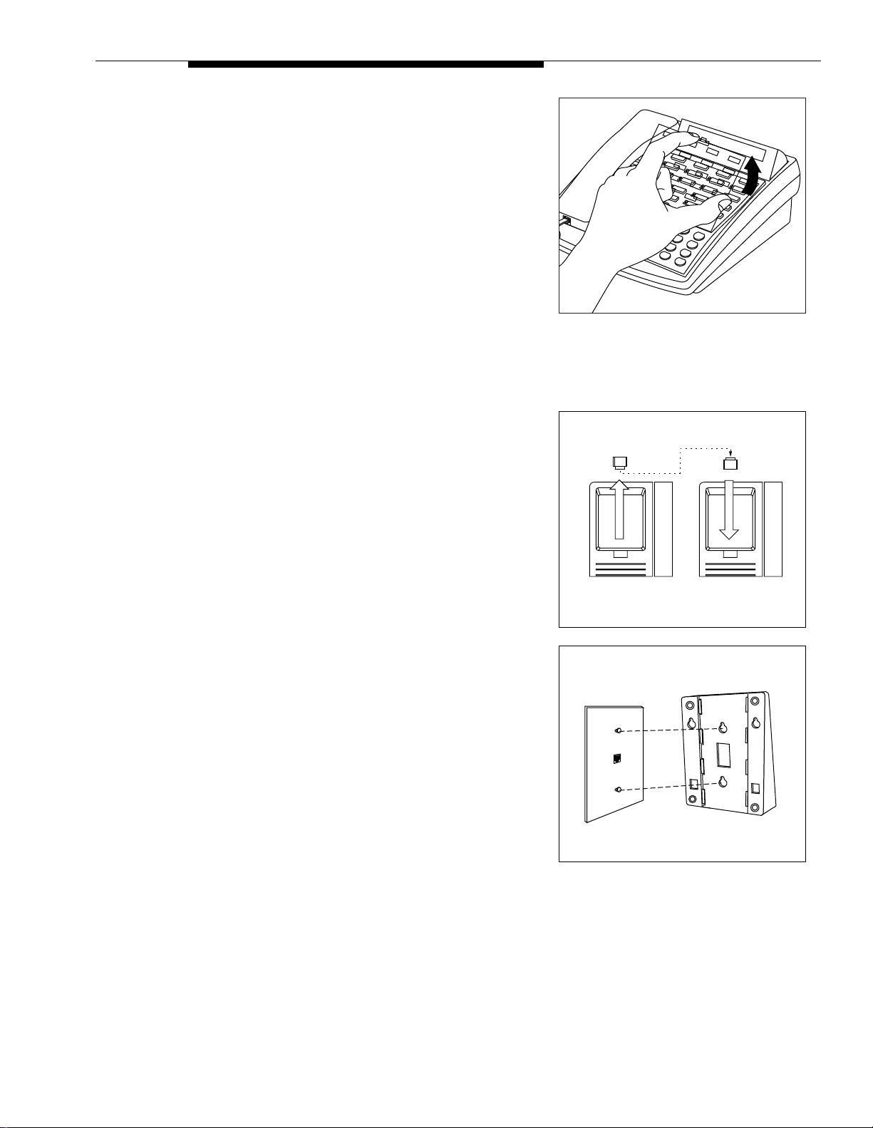
W all Mounting
Wall mounting instructions apply only to PARTNER-model phones. For all other system phones, follow the
instructions provided with the phone.
1 A) Reverse the plastic hook that sits in the earpiece
part of the handset cradle.
B) Turn the phone upside down and remove t he tra y
that holds the
User Instruction
tabs on both sides of the tray near the pull out
tab while you slide the tray straight out.
card s: pre ss the
2 Holding the stand with the wide edge down, mount the
stand on the wall plate using the keyholes on the base
of the stand. For proper mounting, the wall plate must
be a Lucent Tec hnolo gies 630B connectin g block.
Installation Procedures 23
Page 27

3 A) Plug one end of the telephone cord into the jack
in the center of the wall plate.
B) Plug the other end of the telephone cord into the
LINE jack on the bottom of the telephone.
C) Wrap any excess cord around the cord wrap
posts on the bottom inside of the stand.
4 A) To mount the phone on the stand, insert the tabs
on the top of the stand into the
notches on the top edge of the phone.
B) Make sure the telephone cord is neatly wrapped
inside the phone, then rotate the phone down
until the bottom edge snaps into position.
middle
set of
To
LINE
Jack
5 A) Remove the plastic cover from the phone. Label
the button sheet to show any programmed lines
or button features, then place t he button sheet on
the phone so the holes fit over the buttons.
Carefully replace the plastic cover .
B) M ake sure the swivel display is set to the lowest
position.
24 Installation Procedures
Page 28

Connecting and Testing T elephones
1 To connect a phone, plug the modular telephone
mounting cord into a modular wall jack or directly into
a module extension jack. (If you are connecting a
standard phone and its mounting cord is loose, try a
Lucent Tec hno logie s D2R mounting cord instead.)
To install two phones (or other devices) on a single
extension jack, see Combination Extensions earlier in
this guide.
2 Test the telephone for proper operation. To test the
power and lights on a system phone:
PFT
L
I
4
PFT
N
L
E
I
6
S
5
N
1
E
S
7
2
MODULE
3
206
10
11
PFT
12
24
E
13
X
25
T
E
14
26
N
S
I
27
15
O
N
16
28
S
17
29
206
Message
Ext.
Intercom
Intercom
ABC2DEF
Feature
+
31
–
JKL5MNO
GHI
Conf
6
4
TUV8WXYZ
PQRS
Mic
Transfr
9
7
HFAI
Hold
Spkr
#
0
*
MODULE
PFT
18
E
X
19
T
E
20
N
S
I
21
O
N
22
S
23
A) While the phone is idle, press and hold the
#
button for five seconds.
B) Before releasing the
# button, lift the handset.
All lights should light, the ringer should sound,
and (on system display phones only) a test
pattern should appear on the display. (If not, call
for support as instructed on the inside front cover
of this guide.)
C) Replace the handset; the phone is now in normal
operating mode.
Installation Procedures 25
Page 29

Connecting Contact Closure, Call Reporting (SMDR), Paging, and Music-On-Hold Devices
Only steps for connection to the processor module are provided here. See the manufacturer s instructions for more
information about installing and using these devices.
Contact Closure Adjunct
1 Insert the modular plug into the Contact Closure jack,
the first jack on the PARTNER ACS processor module.
2 Route the cord as you did for the line and extension
cords, then connect the other end of the cord to the
jack in the Contact Closure Adjunct.
3 Have a qualified electrician wire the Contact Closure
device or devices to the wiring receptacles in the other
end of the Contact Closure Adjunct. See the
information shipped with the Contact Closure Adjunct
for wiring instructions.
Call Reporting (SMDR) Printer
1 Insert one end of a D8W modular cord into the SMDR
jack, the second jack on the PARTNER ACS processor
module.
2 Plug the other end of the cord into a 355A adapter,
then plug the adapter into the printer s RS-232C serial
port.
Contact
Closure Jack
Contact
Closure
Adjunct
PARTNER 3000
Contact Closure Adjunct
SMDR Jack
Call Accounting
Terminal Printer
(optional)
26 Installation Procedures
Page 30

Paging Sy st em
If you connect a paging system from a
manufacturer other than Lucent Technologies, a
PAGE Jack
paging interface may be required.
1 Insert the modular plug into the PAGE jack on the
PA RTNER ACS processor module (located near the
middle of the processor, just above the line jacks).
2 Route the cord as you did for line and extension cords,
then connect the other end of the cord to the paging
system.
Music-on - H old Audio Sour ce
The performance of music over telephone lines is a public performance under United States Copyright law.
Accordingly, in order for the performance of that music to be lawful, it must be licensed annually to the user by the
copyright owners or their representatives.
You can purchase a Magic On Hold system from Lucent Technologies, 1 800 446-5366, which includes the
required license for the first year. This license must be renewed annually.
Paging System
(optional)
1 Inser t an RCA phon o plug into the MUSIC ON HOLD
jack on the P AR TNER ACS processor module (located
near the middle of the processor, below the line jacks).
2 Route the cord as you did for line and ext ension cords,
then connect the other end of the cord to the audio
source.
3 Place a call on hold and listen. If you do not hear
music at any setting, check Music On Hold (#602)”
and Music On Hold Volume (#614) in Chapter 5 of the
PARTNER Advanced Communications System
Programming and Use
guide.
MUSIC ON HOLD
Jack
30
10
5
01234
METER
VOLUME
COUNTER 2X
TONE
2
0
0
1
0
2
0
1
0
AUTOMATIC TAPE STOP
ALC
ON
OFF
MAGIC ON HOLD
REGISTERED TRADE MARK
RECORD
PLAY
REVIEW
CUE
PAUSE
STOP EJECT
Audio Source
(optional)
Installation Procedures 27
Page 31

Connecting a PARTNER-CA48 Intercom Autodialer
The PARTNER-CA48 Intercom Autodialer is shipped with an adapter, a D8W line cord, a power cord, a power unit,
and a button-labeling sheet.
NOTE:
The PARTNER-CA48 Intercom Autodialer can be wall mounted to work next to a wall-mounted system
phone. See the instructions provided with the Autodialer.
1 Plug the adapter into the wall jack.
Wall Jack Power
Outlet
2 A) Plug one end of the D8W line cord into the J1
jack on the adapter.
B) P lug the other end of the D8W line cord into the
IN jack on the bottom of the autodialer.
Ext.
3 A) Plug the blue-tinted connector (labeled D8AC) of
the power cord into the jack on the power unit.
!
CAUTION:
Use only the power unit supplied with the
PARTNER-CA48 Intercom Autodialer.
Intercom
Message
Intercom
ABC2DEF
Feature
+
–
Conf
Mic
Transfr
HFAI
Hold
Spkr
IN
31
JKL5MNO
GHI
6
4
TUV8WXYZ
PQRS
9
7
#
0
*
OUT
B) Plug the other end (clear tinted) of the power
cord into the J2 jack on the adapter.
C) Plug the power unit into an electrical outlet.
4 Plug the phone s modular telephone cord (LINE jack) into the OUT jack on the bottom of the
autodialer.
5 A) Arrange the autodialer on the desk next to the
phone.
B) Remove the plastic cov er f rom the autodialer and
label the button sheet with employee names.
Place the button sheet on the autodialer, then
carefully replace the plastic cover.
C) Adjust the height of the autodialer to match the
system phone.
NOTE:
If you unplug the system phone that is connected to an
autodialer, you must reset the autodialer. To do so, unplug the
D8W line cord (connected to the IN jack on the bottom of the
autodialer) from the J1 jack on the adapter, then plug it back in.
Intercom
Intercom
Ext.
Feature
Conf
Mic
HFAI
Spkr
Message
1
ABC
Transfr
GHI
2
4
DEF
JKL
3
PQRS
5
Hold
7
MNO
TUV
6
8
W
XYZ
*
9
0
#
28 Installation Procedures
Page 32

Equipment Upgrades
If you are upgrading from a standalone PARTNER ACS processor module to a 2-Slot carrier, see ‘‘Wall-Mounting a
2-Slot Carrier and Modules’’ earlier in this guide for instructions. If you are adding modules to an existing 5-Slot
carrier, see ‘‘
Adding New Modules
Adding New Modules’’, below.
!
WARNING:
Before starting, verify that you have batteries installed
in the PARTNER ACS processor module, and then
disconnect the power cord from the power jack on the
processor module. For an illustration showing the
location of the power jack, see Initializing the System
in this guide.
1 A) Move the On/Off switch to the "Off" position
("O").
On/Off Switch
Power
PARTNER Plus
PFT
L
I
1
N
PFT
E
L
S
2
I
3
N
PFT
E
L
PAGE
S
4
I
N
E
PFT
L
S
I
5
206
MODULE
N
E
S
6
206
MODULE
PFT
PROCESSOR
MODULE
10
PFT
E
206
206
MODULE
MODULE
11
X
16
T
E
E
12
17
X
N
T
S
VOL
E
I
13
18
N
O
S
N
14
I
19
S
MUSIC
O
ON
N
HOLD
15
20
S
21
Jack
B) Loosen the screw on the lower front of the carrier
s cover. Then place one hand on the handle on
the lower front and place your other hand on the
top of the cover.
C) Gently pull the cover up and away from the
carrier be careful not to break the tabs that
attach the cover to the carrier.
2 Before installing a module, make sure the clear , plastic
protector has been removed from the connector area
on the rear of the module. T o remove the protector,
grasp the tabs on the ends of the protector and lift.
Handle
Screw
Tab
Tab
Equipment Upgrades 29
Page 33

3 A) Before you insert the new module, make sure
that all 400 (or 200) modules are installed to the
right of all 206 or 308EC modules. If you need to
move a module to accommodate the new one,
see Replacing System Modules later in this
section.
B) Push slowly but firmly in the center of the module
until the module locks into place, and is attached
to the rear of the carrier. Do not force the
module. If the module does not insert easily,
remove it, clear any obstruction, and reinsert it.
4 A) See ‘‘Connecting Lines and Extensions’’ for
instructions for connecting line and/or extension
jack cords to the new module.
B) Reconnect the power cord.
C) Move the On/Off swi tch to the "On" position
(“—”).
5 Check that all green lights on the fronts of the modules
are lit:
New
206
206
206
Processor
Module
PARTNER
3000
PFT
L
I
PFT
L
N
I
E
N
S
E
S
206
MODULE
400
206
MODULE
PFT
PFT
L
I
N
E
E
X
S
T
E
N
S
I
O
N
S
206
206
MODULE
MODULE
PFT
E
X
T
E
N
S
I
O
N
S
Lights
If a single light is out,
A)
power down the control
unit, reseat the module, then power up the
control unit.
If multiple lights are out,
power down the control
unit, reseat the leftmost module that has a light
out, then power up the control unit.
If the lights are still out,
B)
call for support as
instructed on the inside front cover of this guide.
6 A) Make sure all modules are seated properly. The
cover will not fit if the modules are not seated
properly .
B) To replace the cover, grasp it by its upper edges
and hold it squarely over the control unit.
C) Place the cover over the modules and make sure
it fits firmly in place.
D) Tighten the screw on the lower front of the cover.
Screw
PFT
L
I
N
E
S
PARTNER Plus
PFT
L
I
1
N
PFT
E
L
S
2
I
3
N
PFT
E
L
PAGE
S
4
I
N
E
PFT
L
S
I
5
206
MODULE
N
E
S
6
206
MODULE
PFT
PROCESSOR
MODULE
10
PFT
E
206
206
MODULE
MODULE
11
X
16
T
E
E
12
17
X
N
T
S
VOL
E
I
13
18
N
O
S
N
14
I
19
S
MUSIC
O
ON
N
HOLD
15
20
S
21
PFT
L
I
N
E
S
30 Equipment Upgrades
Page 34

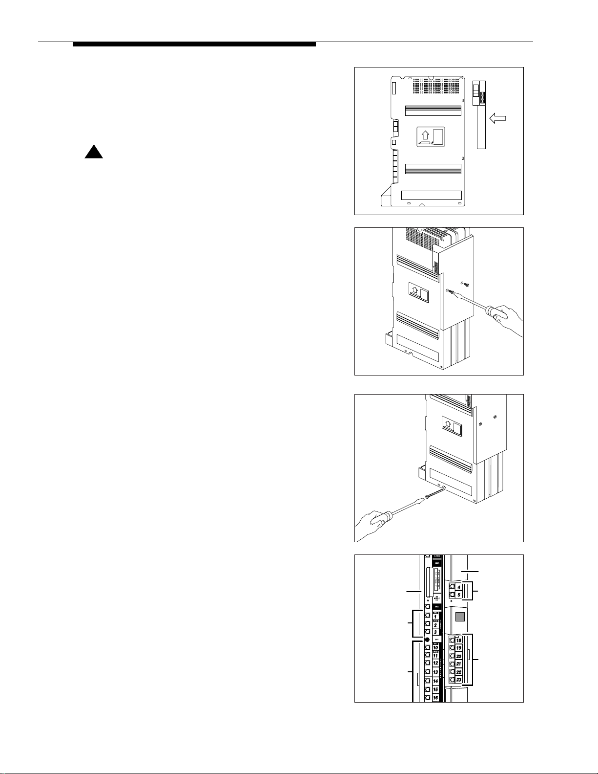
Replacing System Modules
The procedure for replacing a module depends on your configuration:
If you have a... See...
Standalone PARTNER ACS processor
module configuration
2-Slot carrier configuration ‘‘
5-Slot carrier configuration ‘‘Replacing Modules in a 5-Slot Carrier’’
Replacing a Standalone PARTNER ACS Processor Module
!
WARNING:
Disconnect the power cord from the power jack on the processor module. For an illustration
showing the location of the power jack, see ‘‘
Replacing a Standalone PARTNER ACS
‘‘
Processor Module’’
Replacing Modules in a 2-Slot Carrier’’
Initiali z ing the System’’ earlier in this guide.
1 Check the slack in the wires. If there is not enough
slack to remove the module without pulling the line
and extension cords free, label and disconnect the
wires before continuing.
2 Remove the screws at the top and bottom of the
module, and remove the module from the wall.
3 Follow the instructions in ‘‘Wall-Mounting a Standalone
PARTNER ACS Processor Module’’ and ‘‘Inserting
Batteries in the PARTNER ACS Processor
Module’’ear lier in this guid e.
4 Connect the line and extension cords one at a time,
making sure to place the correct cords into their
corresponding jacks on the new module. (See
‘‘
Connecting Lines and Extensions’’ earlier in this
guide.)
5 Reconnect the power cord.
Replacing Modules in a 2-Slot Carrier
!
WARNING:
Before starting, verify that you have batteries installed in the PARTNER ACS processor module,
and then disconnect the power cord from the power jack on the carrier. For an illustration showing
the location of the power jack, see I‘‘
PARTNER
3000
Initializing the System’’ea rlier in this guide.
Equipment Upgrades 31
Page 35

1 Check the slack in the wires. If there is not enough
slack to remove the modules without pulling the line
and extension cords free, label and disconnect the
wires before continuing.
2 Remove the long screw at the bottom of the modules.
3 Remove the screws that attach the carrier to the
modules.
4 Pull the carrier to the right to remove it.
5 A) Slide the top module to the left to disengage its
interlocking mounting tracks from the PARTNER
ACS processor module.
B) I f you are replacing the PA RTNER ACS
processor module, skip to Step 7. If you are
replacing the top module, continue with Step 6.
6 Mount the new module by following Steps 3 through 8
in ‘‘
Wall-Mounting a 2-Slot Carrier and Modules’’,
earlier in this guide, and then skip to Step 8 below.
PARTNER
206
MODULE
Mounting
Tracks
32 Equipment Upgrades
Page 36

7 A) Remove the screw at the top of the PARTNER
ACS processor module and remove the module
from the wall.
B) Mount the new P ARTNER ACS processor
module by following the instructions in
‘‘
Wall-Mounting a Standalone PAR TNER A CS
Processor Module’’ and ‘‘Inserting Batteries in
the PARTNER ACS Processor Module’’ earlier in
this guide.
C) Remount the top module by following Steps 1
and 3 through 9 in ‘‘
Wall-Mounting a 2-Slot
Carrier and Modules’’ earlier in this gu ide .
8 Connect the line and extension cords one at a time,
making sure to place the correct cords into their
corresponding jacks on the new module. (See
‘‘
Connecting Lines and Extensions’’ earlier in this
guide.)
9 Reconnect the power cord.
PARTNER
3000
Replacing Modules in a 5-Slot Carrier
!
WARNING:
Before starting, move the On/Off switch to "off", and unplug the power cord. Verify that you have
batteries installed in the PARTNER ACS processor module, and then disconnect the power cord
from the wall jack on the carrier.
1 A) Loosen the screw on the lower front of the carrier
s cover. Then place one hand on the handle on
the lower front and place your other hand on the
top of the cover.
B) Gently pull the cover up and away from the
carrier be careful not to break the tabs that
attach the cover to the carrier.
Handle
Screw
On/Off Switch
Power
PARTNER Plus
PFT
L
I
1
N
PFT
E
L
S
2
I
3
N
PFT
E
L
PAGE
S
4
I
N
E
PFT
L
S
I
5
206
MODULE
N
E
S
6
206
MODULE
PFT
PROCESSOR
MODULE
10
PFT
E
206
206
MODULE
MODULE
11
X
16
T
E
E
12
17
X
N
T
S
VOL
E
I
13
18
N
O
S
N
14
I
19
S
MUSIC
O
ON
N
HOLD
15
20
S
21
Jack
Equipment Upgrades 33
Page 37

2 Before installing a module, make sure the clear, plastic
protector has been removed from the connector area
on the rear of the module. To remove the protector,
grasp the tabs on the ends of the protector and lift.
3 A) Check the slack in the wires. If there is not
enough slack to remove the module without
pulling the line and extension cords fr ee, label
and disconnect the wires before continuing with
Step 3B.
B) Place one hand on top of the module. With your
other hand, grip the plastic bracket on the bottom
front of the module, and pull out the old module.
C) If you are replacing a module with one of a
different type, make sure that all 400 (or 200)
modules are installed to the right of all 206 or
308EC modules and that the PARTNER ACS
processor module remains in the center slot.
D) To insert the replacement, push slowly but firmly
in the center of the module until the module locks
into place, and is attached to the rear of the
carrier.
!
CAUTION:
Do not force the module. If the module does not insert
easily, remove it, clear any obstruction, and reinsert it.
Tab
Tab
PARTNER
3000
PFT
L
I
N
E
S
206
MODULE
PFT
E
X
T
E
N
S
I
O
N
S
4 A) Connect the line and extension cords one at a
time, making sure to place the correct cords into
their corresponding jacks on the new module.
(See ‘‘
Connecting Lines and Extensions’’ earlier
in this guide.)
B) Reconnect the power cord.
C) Move the carrier s On/Off switch to the "On"
position (“—”).
5 Check that all green lights on the fronts of the modules
are lit:
If a single light is out
A)
unit, reseat the module, then power up the
control unit.
If multiple lights are out
B)
unit, reseat the leftmost module that has a light
out, then power up the control unit.
If the lights are still out
C)
instructed on the inside front cover of this guide.
, power down the control
, power down the control
, call for suppor t as
PFT
Lights
L
I
N
E
S
PFT
L
I
N
E
S
34 Equipment Upgrades
Page 38

6 A) Make sure all modules are seated properly. The
PFT
PFT
E
X
T
E
N
S
I
O
N
S
L
I
N
E
S
MODULE
206
PFT
L
I
N
E
S
MODULE
206
PARTNER
3000
cover will not fit if the modules are not seated
properly .
B) To replace the cover, gr asp it by its upper edges
and hold it squarely over the control unit.
C) Place the cover over the modules and make sure
it fits firmly in place.
D) Tighten the screw on the lower front of the cover.
PARTNER Plus
PFT
L
I
1
N
PFT
E
L
S
2
I
3
N
PFT
E
L
PAGE
S
4
I
N
E
PFT
L
S
I
5
206
MODULE
N
E
S
6
206
MODULE
PFT
PROCESSOR
MODULE
10
PFT
E
206
206
MODULE
MODULE
11
X
16
T
E
E
12
17
X
N
T
S
VOL
E
I
13
18
N
O
S
N
14
I
19
S
MUSIC
O
ON
N
HOLD
15
20
S
21
Inserting or Removing a PC Card
!
CAUTION:
Before starting, verify that you have batteries installed in the PARTNER ACS processor module.
1 If you have an existing 5-Slot carrier, move the carrier
s On/Off switch to the "Off" position ("O"). F or al l types
of installations, disconnect the power cord from the
power jack. For illustrations showing the location of the
power jack on the various configurations, see
‘‘
Initiali zi ng the System’’ e arlier in th is guid e.
2 If you do not have a 5-slot carrier, go to Step 3. If you
have a 5-slot carrier:
A) Loosen the screw on the lower front of the cover .
Then place one hand on the handle on the
bottom front of the cover and place your other
hand on the top of the cover.
B) Gently pull the cover up and away from the
carrier be careful not to break the tabs that
attach the cover to the carrier.
Screw
Handle
Screw
On/Off Switch
Power
PARTNER Plus
PFT
L
I
1
N
PFT
E
L
S
2
I
3
N
PFT
E
L
PAGE
S
4
I
N
E
PFT
L
S
I
5
206
MODULE
N
E
S
6
206
MODULE
PFT
PROCESSOR
MODULE
10
PFT
E
206
206
MODULE
MODULE
11
X
16
T
E
E
12
17
X
N
T
S
VOL
E
I
13
18
N
O
S
N
14
I
19
S
MUSIC
O
ON
N
HOLD
15
20
S
21
Jack
3 Insert the PC Card in the PC Card slot on the
PARTNER ACS processor module. When inserted
properly, the PC Card projects about 1-5/8” (4 cm)
from the module.
4 Power up the system:
A) Reconnect the power cord.
B) I f you have a 5-Slot carrier, move the carrier s
On/Off switch to the "On" position.
Equipment Upgrades 35
Page 39

5 Check that all green lights on the fronts of the modules
are lit:
If a single light is out,
A)
unit, reseat the module, then power up the
control unit.
If multiple lights are out,
B)
unit, reseat the leftmost module that has a light
out, then power up the control unit.
power down the control
power down the control
PFT
Lights
L
I
N
E
S
PFT
L
I
N
E
S
If the lights are still out
C)
, call for suppor t as
instructed on the inside front cover of this guide.
6 A) If you have a 2-Slot carrier or a standalone
configuration, you are finished with this
procedure. If you have a 5-Slot carrier, continue
with Step 5B.
B) M ake sure all modules are seated proper ly. The
cover will not fit if the modules are not seated
properly .
C) To replace the cover, grasp it by its upper edges
and hold it squarely over the control unit.
D) Place the cover over the modules and make sure
it fits firmly in place.
E) Tighten the screw on the lower front of the cover .
Screw
PARTNER Plus
PFT
L
I
1
N
PFT
E
L
S
2
I
3
N
PFT
E
L
PAGE
S
4
I
N
E
PFT
L
S
I
5
206
MODULE
N
E
S
6
206
MODULE
PFT
PROCESSOR
MODULE
10
PFT
E
206
206
MODULE
MODULE
11
X
16
T
E
E
12
17
X
N
T
S
VOL
E
I
13
18
N
O
S
N
14
I
19
S
MUSIC
O
ON
N
HOLD
15
20
S
21
36 Equipment Upgrades
 Loading...