

Page 1

Lucent Technologies
Bell Labs Innovations
PARTNER® II Communications System
PARTNER® Plus Communications System
Release 4.1
System Planner
518-455-338
Issue 2
August 1996
Page 2
Copyright © 1996 Lucent Technologies
All Rights Reserved
Printed in U.S.A.
518-455-338
Issue 2
August 1996
Notice
Every effort was made to ensure that the information in this Planner was
complete and accurate at the time of printing. However, information is
subject to change.
Trademarks
PARTNER and PassageWay are registered trademarks and
PARTNER MAIL and PARTNER MAIL VS are trademarks of
Lucent Technologies.
Ordering Information
The order number for this Planner is 518-455-338. To order additional
copies, call 1 800 457-1235 or 1 317 361-5353. For information on how to
order other reference materials, see the PARTNER II Communications
System Programming and Use guide or the PARTNER Plus Communications System Programming and Use guide.
Support Telephone Numbers
In the continental U.S., Lucent Technologies provides a toll-free
customer hotline 24 hours a day. Customers can call the hotline at
1 800 628-2888 if they need assistance when programming or using
the system.
Outside the continental U.S., customers should contact their
Lucent Technologies Representative or local Authorized Dealer.
Contents
Introduction
Form A Supplemental Instructions: System Configuration
Form B1 Supplemental Instructions: System Extensions
Form B2 Supplemental Instructions: Customized Extension Settings
Form C Supplemental Instructions: Button Templates
Form D Supplemental Instructions: Number Lists
Form E Supplemental Instructions: System Speed Dial Numbers
Form A: System Configuration
Form B1: System Extensions
Form B2: Customized Extension Settings
Form C1: PARTNER-34D Telephone
Form C2: Intercom Autodialer
Form C3: PARTNER-18 Telephone
Form C4: PARTNER-6 Telephone
Form C5: MLS-34D Telephone
Form C6: MLS-18 Telephone
1
2
5
6
8
14
16
Form C7: MLS-12 Telephone
Form C8: MLS-6 Telephone
Form D: Number Lists
Form E: System Speed Dial Numbers
Page 3

Introduction
Setup decisions for the PARTNER® II Communications System or PARTNER
Plus Communications System should be recorded on the forms in this Planner.
The forms must be filled out before installation to provide guidance for the
technician who installs and programs the system.
The forms should also be used by the customer to record changes after
installation, so there is an ongoing record of the programming for the system. If
programming is inadvertently erased (for example, in the event of an extended
power failure), the forms can be used to reprogram the system.
Identifying a System Manager
As part of the planning process, the customer should identify a person in the
company to act as System Manager. The System Manager is the person who
is responsible for the telephone system. The System Manager should work
with you to fill out the forms, and should participate (with an alternate) in the
training for the system. The System Manager can then provide training, answer
questions for telephone users, and perform programming for the system after
installation.
2.
Provide advice to help the customer fill out any additional forms needed for
installation.
If button features should be programmed onto users’ telephones cen-
■
trally (instead of letting users do it themselves), the desired button
programming should be specified using the appropriate telephone
templates or feature checklists on Form C1 through Form C8.
If the customer plans to use dialing restrictions, Form D should be
■
used to specify a list of Emergency Phone numbers that will override
restrictions. Form D can also be used to specify lists of Disallowed
and Allowed numbers to fine tune the dialing capabilities for individual
extensions, to identify External Hotline phones that dial a specified
telephone number as soon as the handset is lifted, and to specify up
to 99 account codes for account code verification.
■
If the customer wants System Speed Dial numbers programmed that will
be available to all system users, Form E should be filled out.
After the forms are completed, take the original and leave a copy with the
customer.
Filling Out Planning Forms for the Customers
The planning forms were designed to be as self explanatory as possible. The
first few times you fill out the forms, it may help to refer to the supplemental
instructions on the pages that follow. For detailed information about system
features, see the PARTNER II or PARTNER Plus Communications System
Programming and Use guide.
We suggest you complete the forms as follows:
Fill out Form A (to describe the customer’s overall system configuration)
1.
and Form B1 (to record basic information for each system extension).
If you want to customize extension settings for different users, complete
Form B2 as well.
NOTE: For system options that require programming, the forms show the
name of the procedure and the programming code in the form {#NNN} (for
example,
for individual extensions are identified by the letters {CTP} for "Centralized
Telephone Programming" (for example, Line Ringing {CTP}).
Line Assignment {#301});
centralized programming procedures
Customer Training
In the U.S., a Lucent Technologies representative will provide training at the
customer’s place of business when the system is installed and programmed.
(Outside the U.S., customers should contact their Lucent Technologies Representative or local Authorized Dealer for information about training.) The representative will demonstrate how to:
■
Handle calls and use system features
■
Program features and phone numbers onto phone buttons
■
Change the programming for the system and for individual telephones
■
Use the Quick Reference cards and the Programming and Use guide
To prepare for training, please tell the customer to:
■
Set aside approximately two hours of uninterrupted time for training on
installation day, preferably in a quiet place away from distractions.
■
Designate one person (generally the System Manager) and an alternate to
participate in the training. These persons will then train the rest of the
company staff.
This training will ensure that the customer takes maximum advantage of their
new Lucent Technologies system. Thank you for your cooperation.
1
Page 4

Form A Supplemental Instructions: System Configuration
2
Salesperson completes items 1–12.
Sales Support Representative completes items 13–15.
6. Configure Hardware for Hybrid Mode
For PARTNER II systems only, check "Yes" if the customer wants line pooling
capabilities; otherwise check "No."
By default, the system is configured for Key mode. Changing to Hybrid mode
requires Lucent Technologies Authorized Personnel to modify the processor
module at installation.
IMPORTANT: In some jurisdictions in the U.S., a PARTNER II system installation for Hybrid mode requires Federal Communications Commission (FCC)
registration information to be reported to the customer’s local telephone company. This includes the system’s operating mode (MF for Hybrid mode) and its
FCC registration number, which can be found on the right side of the primary
carrier. Although it is the customer’s responsibility to report FCC registration
information, it is highly recommended that you report this information for the
customer.
8. System Lines
Enter information about individual lines in the table. Be sure to list the lines
assigned to all extensions first, followed by personal and dedicated lines.
Write R if Rotary (Dial Pulse) Line {#201}
Leave blank for touch-tone lines.
Hybrid Mode Only—Write auxiliary pool 881, 882, 883, or No Pool {#207}
(PARTNER II system only) The default for Hybrid mode is all lines assigned
to the main pool (880). To create auxiliary pools, specify the auxiliary pool
access code 881, 882, or 883. To identify lines that can be assigned to
pooled extensions as individual lines, write "No Pool."
Line Coverage—You can select one per line
If desired, identify an automated answering option for incoming calls on each
line. (If all calls on a line should be covered by a human operator, leave all
line coverage columns blank for that line.) To avoid confusing callers, it is
recommended that only one of the AA, DXD, or VMS-AA options be
used to handle incoming calls throughout the system.
AA
DXD
Automated Attendant service by PARTNER Attendant, which
must be purchased separately.
Direct Extension Dialing (PARTNER II system only) lets
callers dial extensions without waiting for the receptionist.
VMS-AA
ASA
Hunt Group
VMS-Mail
Write Ext. No. for Call Cover {#208}
(PARTNER II system only) If the customer wants a user who has a personal
or individual line to be able to activate Call Coverage for that line, identify
that user’s extension number in this column. Programmed using Line
Coverage Extension {#208}.
NOTE: Only one owner can be assigned to a specific line. However, multiple
lines can be assigned ownership to the same extension.
Write User’s Name for Personal or Owned Line
or Identify Equipment for Dedicated Line
For a personal, owned, or dedicated line, write the user name or equipment
description (for example, "Fax"); otherwise, leave blank. (If another user
provides backup call coverage on the line, note the name of that user in
parentheses.) Use Form B2 to record custom extension assignments.
Check if Caller ID Service
(PARTNER II system only) Check this column to indicate lines on which
local telephone company Caller ID service is provided. For dial-code
features that support this service, see Form C.
Automated Attendant service of PARTNER MAIL™ or
PARTNER MAIL VS™, which must be purchased separately.
If the receptionist does not answer an incoming call, VMS-AA
lets the caller select an extension or route. Programmed using
option 1 of Group Call Distribution {#206} for Hunt Group 7.
Automatic System Answer (PARTNER II system only) plays
a recorded message, then places the call on hold, disconnects
the call, or continues to ring available extensions.
Hunt Group sends incoming calls directly to an extension in
the specified group 1–6. Programmed using option 1 of Group
Call Distribution {#206}.
Voice Mail coverage of personal line by PARTNER MAIL or
PARTNER MAIL VS, which must be purchased separately.
Sends unanswered incoming calls directly to the line owner’s
mailbox.
NOTE: You can use option 3 of Group Call Distribution {#206}
or Line Coverage Extension {#208} to specify VMS-Mail lines
for ownership. With the #206 option, calls are routed to the
user’s voice mailbox after four rings. The #208 option provides
more flexibility because calls are routed after the number of
rings specified with VMS Cover Rings {#117}, if the extension
has VMS Cover on. The user also can turn on Do Not Disturb
to send calls on the owned line immediately to VMS coverage.
Page 5

9. System Settings
Receptionist answers calls during business hours?
If "Yes," be sure to record settings on these forms that will allow
the receptionist to answer the phone before automatic coverage is applied.
Number of Lines {#104}
This programming procedure should be used only for installation—using it
later erases custom settings for all extensions. After installation, use Line
Assignment {#301} to assign lines and, for PARTNER II systems only, Pool
Extension Assignment {#314} to assign lines to pools.
Transfer Return Rings {#105}
The transfer return extension is identified on Form B1, Write Transfer Return
Ext. No. {#306}.
Outside Conference Denial {#109}
To prevent all users from conferencing with more than one outside party,
write "No" in the space provided.
Call Coverage Rings {#116}
(PARTNER II system only) Covered extensions are identified on Form A,
Write Ext. No. for Call Cover {#208}.
VMS Cover Rings {#117}
This feature applies to all intercom calls, transferred calls (that is, outside
calls transferred by VMS-AA and inside transferred calls), and outside calls
on owned lines (those specified using Line Coverage Extension {#208}) for
extensions that have VMS Cover or Automatic VMS Cover {#310} active.
Ring on Transfer {#119}
If Ring on Transfer is Not Active, callers hear silence unless Music on Hold is
activated and an audio source is connected to the processor module.
Music on Hold {#602}
If Music on Hold is Not Active or no audio source is connected, callers on
hold hear silence.
10. Line Coverage
DXD
If DXD was specified in Item 8, you can change the number of times that the
phone should ring before the system answers. You must specify the
message callers hear when the system answers. Be sure to specify a Direct
Extension Dial Button {#113} for extension 10 on Form C to activate this
feature.
VMS-AA
If VMS-AA was specified in Item 8, you can change the number of times that
the phone should ring before the voice messaging system answers. You also
can specify that the system should answer only when Night Service is off
(Day only) or when Night Service is on (Night only). If Day only or Night only
is selected, be sure to specify a Night Service Button {#503} for extension 10
on Form C to activate this feature.
ASA
If ASA was specified in Item 8, you can change the number of times that the
phone should ring before the system answers and indicate how the system
should handle the call after the greeting plays. You must specify the
message callers hear when the system answers. Be sure to specify an
Automatic System Answer Button {#111} for extension 10 on Form C to
activate this feature.
Toll Call Prefix {#402}
If dialing a "0" or "1" to make long distance calls is not required, write "No" in
the space provided.
System Password {#403}
Whoever knows the password can place any type of call at any time,
regardless of dialing restrictions.
NOTE: If a System Password is programmed, it must be entered to turn
Night Service on and off. Also, users at Night Service Group extensions
must enter the password before placing outside calls—except Marked
System Speed Dial numbers and numbers on the Emergency Phone
Number List.
3
Page 6

11. Auxiliary Equipment (System)
Check boxes that apply for auxiliary equipment connected to the control unit or
to system wiring. All appropriate hardware and software must be purchased
separately.
Battery Backup
In some countries, battery backup is available to allow the customer to
connect an external battery to keep the complete system operational during
a commercial power failure. If it is available and the customer wants battery
backup, check this box.
Caller ID Devices
If the customer wants to connect a Caller ID device (such as a PC to
process Caller ID information) directly to a system line, check this box.
A separate wiring run is required to connect each device directly to the
network interface jack for a line.
Loudspeaker Paging
If the customer wants a loudspeaker paging system, check this box. If the
loudspeaker paging system supports multiple zones, indicate the number of
zones.
4
Magic on Hold
If the customer wants Magic On Hold, check this box. Magic On Hold does
not require a license.
Uninterruptible Power Supply
If the customer cannot afford to lose full communications capability during
power outage, an uninterruptible power supply (UPS) should be ordered.
SMDR
If the customer wants to track phone usage in a printed report, check this
box. Before changing SMDR Output Format {#610} to 24 digits, check the
documentation for the call accounting device to verify that 24-digit output is
supported.
Page 7

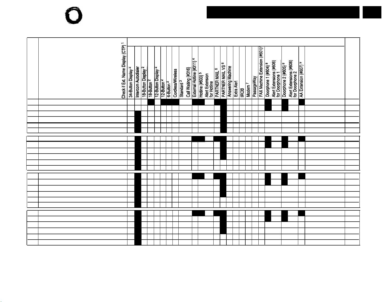
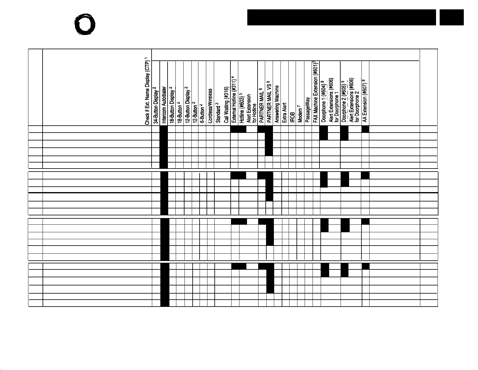
Form B1 Supplemental Instructions:
System Extensions
This form provides basic information for each system extension. To customize
line restrictions or other extension settings, you must also use Form B2.
PARTNER MAIL
Write Name/Description
Write a user name or a description for auxiliary equipment (such as "Fax," "VMS,"
or "Conference Room") to be installed at the extension. If system display phones
should show the name/description of the caller for internal calls, write the 20
characters you want to display, check the Check if Ext. Name Display {CTP}
column, and complete Form B1, page 3 of 4 and page 4 of 4. (Note that
MLS-model phones display only 12 characters.)
These VMS extensions should be checked on Form B2, Identify Group
PARTNER MAIL VS
Identify Telephone Attached to this Extension
Check the appropriate column to indicate the type of phone.
If a system and standard phone are combined on an extension, check the two
appropriate Identify Telephone columns. If a phone and an auxiliary device are
combined on the extension, check the appropriate Identify Telephone and
Identify Auxiliary Equipment columns.
Write Name/Description column. Note that the PARTNER MAIL VS module
as guest mailboxes.
These VMS extensions should be checked on Form B2, Identify Group
Assignments, VMS Only. They must be assigned to Hunt Group 7 using Hunt
Identify Auxiliary Equipment
Attached to this Extension
Except as noted, check the appropriate column to indicate the type of auxiliary
equipment.
Call Waiting {#316}
(Standard phones only) By default, the system’s Call Waiting feature is set for
Not Active. To change the default, check extensions with standard phones
that are to receive a tone while on a call to indicate a second incoming call.
External Hotline {#311}
Check the extensions to be used as External Hotlines. Specify the telephone
number that is dialed automatically from each External Hotline on Form D.
Hotline {#603}
Write "Hotline" in the Write Name/Description column and write "T" for touchtone or "R" for rotary in the Standard column (under Identify Telephone) to
indicate the phone type. (A hotline extension should have a standard touchtone or rotary phone; a hotline alert extension can have any phone type.)
Extra Alert
connected.
IROB
AA Extension {#607}
Write Transfer Return Ext. No. {#306}
By default, a transferred call returns to the originating extension if the call is not
picked up. To specify a different transfer return extension, write the extension
number in this column. For extensions to which you are connecting a PARTNER
MAIL system, PARTNER MAIL VS system, or PARTNER Attendant, indicate a
transfer return extension—usually extension 10—where a person can pick up
calls that are transferred by the VMS or AA extension but not answered.
Check the 2 or 4 extensions used to connect the PARTNER MAIL system and
write "VMS" in the Write Name/Description column.
NOTE: In addition to the VMS extensions, you must specify an extension
(with no lines assigned) where a remote maintenance device is installed.
Write "VMS-RMD" in the Write Name/Description column.
Assignments, VMS Only. They must be assigned to Hunt Group 7 using Hunt
Group Extensions {#505}.
Check the 2 extensions used for PARTNER MAIL VS and write "VMS" in the
is installed in a control unit slot, and so takes up 6 extensions. Only the
bottom 2 extensions, however, answer VMS calls—the other 4 can be used
Group Extensions {#505}.
Check the extensions to which an extra alert, such as a light or bell, is
Check the extensions to which an In-Range Out-of-Building protector is
connected to prevent electrical surges.
Check the extensions to which PARTNER Attendants are connected.
If DXD line coverage is used (see Form A), you also should specify a transfer
return extension for extension 10 to provide backup coverage for calls that are
not answered at extension 10 or at an extension that the caller selects.
5
Page 8

Form B2 Supplemental Instructions:
Customized Extension Settings
6
Each row on Form B2 specifies settings—including group assignments—that
can be copied to other extensions using Copy Settings {#399}. Default settings
are shown at the top of Form B2.
Settings for Auxiliary Equipment
The following settings may be useful for auxiliary equipment:
■
For a dedicated line (such as a Fax line, see Form A), assign the line to the
equipment extension and remove it from other extensions.
■
To prevent other extensions from interrupting calls, write "A" (Assigned) in
the Automatic Extension Privacy {#304} column.
■
In general, do not assign auxiliary equipment extensions to a Pickup Group,
Calling Group, Hunt Group, or Night Service Group.
Identify Extension Settings if Different from
Default
For each extension, identify extension settings that are different from the default.
Display Language {#303}
(System display phones only) Indicate the language for display messages if
different from English.
Automatic Extension Privacy {#304}
By default, any user sharing a line can join calls at another extension
(Privacy is Not Assigned). If all calls are to be private, write "A" (Assigned) in
this column. Always use this feature for Fax and modem extensions.
Abbreviated Ringing {#305}
(System phones only) By default, a new call rings only once when a phone is
in use (Abbreviated Ringing is Active); the line button light flashes until the
call is answered or the caller hangs up. To change the default so a new call
rings repeatedly, write "NA" (Not Active) in this column.
Forced Account Code Entry {#307}
(System phones only) If a user should be required to enter an account code
before placing an outside call, write "A" (Assigned) in this column.
Distinctive Ring {#308}
(Standard devices only) By default, outside, intercom, and transferred calls
each have their own ringing pattern (Distinctive Ringing is Active). To change
the default so that all calls ring the same, write "NA" (Not Active) in this
column.
Automatic VMS Cover {#310}
If PARTNER MAIL or PARTNER MAIL VS is installed and an extension
should automatically be covered when its calls are not answered, write "A"
(Assigned) in this column. To program a VMS Cover button to turn coverage
on and off at an extension, see Form C.
Voice Interrupt on Busy {#312}
(System phones only) To identify an extension as being eligible for intercom
calls while busy with another intercom or outside call, write "A" (Assigned) in
this column.
Line Access Mode {#313}
(PARTNER II system only) If the system has been set up for Hybrid mode, all
extensions (except 10) operate as pooled extensions by default. To identify
extensions that are to operate as key extensions, write "K" (Key) in this
column. Extension 10 always operates as a key extension.
Hybrid Mode Only—List individual lines {#301}
For pooled extensions, list line numbers to identify individual lines to be
assigned to extensions. By default, all lines are assigned to extension 10.
Line Ringing {CTP}
The default is immediate ringing for all individual lines at all extensions. For
pools, the default is no ring. For each extension, specify the lines or pools that
should ring immediately, after a delay (about 20 seconds), or that should not
ring. Also specify the lines or pools that should not be assigned.
Settings for a Receptionist’s Extension
If a receptionist at extension 10 is to answer calls, coordinate line assignments
and line ringing for extension 10 with settings for other extensions, to determine how incoming calls are handled.
■
If the receptionist is to answer all calls (immediate call handling), assign
all lines to extension 10 with immediate ringing; assign lines or pools as
needed to other extensions with no ringing. The receptionist will answer all
calls and transfer them to the appropriate extensions. If you want another
extension to provide backup coverage for the receptionist, assign all lines
to that extension with delayed ringing.
In Hybrid mode, immediate call handling is the factory setting for extension
10. (Lines are assigned to individual line buttons on the phone at extension
10 and all pools assigned to users’ extensions are set to no ring.)
■
If the receptionist is to answer calls only when users do not pick up immediately (delayed call handling), set lines or pools to immediate ringing at
users’ extensions and to delayed ringing at extension 10.
Page 9

Identify Restrictions/Permissions
Specify restrictions and permissions for each extension.
Line Access Restriction {#302} or
Pool Access Restriction {#315}
By default, access to all lines and pools is set to No Restriction. To change
the default, write the line numbers or pool access codes in the appropriate
columns, as follows:
Outgoing only –
Incoming only –
No Access
NOTE: Pool Access Restriction for key extensions in Hybrid mode is set to
No Access.
Outgoing Call Restriction {#401}
Write "IN" or "LOC" to indicate restrictions for all outgoing calls on all lines at
that extension, as follows:
–
IN
LOC
Any available outside lines can still be used to dial numbers on an Allowed
Phone Number List assigned to the extension, numbers on the Emergency
Phone Number List, or Marked System Speed Dial numbers.
User can make only intercom calls to other system extensions.
–
User can make only intercom and local outside calls (no calls that
require a "0" or "1" prefix).
User can place outside calls and receive only
transferred calls on specified line or pool.
User cannot place outside calls but can receive calls
on specified line or pool.
–
User cannot place or receive outside calls on
specified line or pool (but can receive transferred
calls, pick up calls on hold, or join calls in Key mode
and on key extensions in Hybrid mode).
Identify Group Assignments
To assign extensions to any of the following groups (each extension can be in
one or more groups), write the group number or place a check mark in the
appropriate columns.
Pickup Group Extensions {#501}
Any extension can answer an intercom, transferred, or outside call ringing at
an extension in the Pickup Group, without knowing which extension is ringing
and without being in the group. Do not put PARTNER MAIL or PARTNER
MAIL VS extensions in a Pickup Group.
Calling Group Extensions {#502}
A user can ring or page (voice signal) all extensions in a Calling Group
simultaneously or transfer a call by ringing the group. Once an extension
answers, the ringing or paging stops at the other extensions in the group. Do
not assign extensions connected to auxiliary equipment, PARTNER MAIL,
PARTNER MAIL VS, or External Hotlines to a Calling Group.
If a loudspeaker paging system is connected and Simultaneous Paging is
desired, put all desired system phones with speakers in Calling Group 1.
NOTE: When the user voice signals an extension that has a system phone,
the phone beeps and the user’s voice is heard through its built-in speaker.
System phones are the only ones that can be voice signaled.
Hunt Group Extensions 1–6 {#505}
Calls can ring or be transferred to the first non-busy extension in a Hunt
Group. A call rings at an extension in a Hunt Group three times; if it is not
answered, it hunts to the next non-busy extension, continuing until someone
answers or the caller hangs up. (If you voice signal a Hunt Group, only the
first extension is signaled; the call does not keep hunting if there is no
answer.) Incoming calls on specific lines can be directed to a Hunt Group
using Group Call Distribution {#206}. Do not put PARTNER MAIL or
PARTNER MAIL VS extensions in Hunt Groups 1–6.
VMS Only (Hunt Group 7)
For extension where PARTNER MAIL or PARTNER MAIL VS is connected,
check this box to assign the extension to Hunt Group 7. The system
recognizes any extensions assigned to Hunt Group 7 as Voice Mail Service
(VMS–either PARTNER MAIL or PARTNER MAIL VS) extensions. Do not
assign any extensions other than VMS extensions to Hunt Group 7. Also, do
not assign PARTNER MAIL or PARTNER MAIL VS extensions to any other
Hunt Groups, to any Calling or Pickup Groups, or to the Night Service Group.
Night Service Group Extensions {#504}
Check this box if the extension should be in the Night Service Group. When
Night Service is on, incoming calls on assigned lines or pools ring immediately
at the extensions in the Night Service Group, even if Line Ringing for those
extensions is set for "delayed ring" or "no ring." Do not put PARTNER MAIL
or PARTNER MAIL VS extensions in the Night Service Group.
7
Page 10

Form C Supplemental Instructions: Button Templates
8
There are eight pages to Form C—one page for each type of system phone and
one page for an Intercom Autodialer. Use Form C to record line and pool button
assignments and to indicate programming for system telephone buttons that do
not have lines or pools assigned if the programming is to be performed from
extension 10 or 11 during system installation. After installation, users can program
additional features using the instructions on their Quick Reference cards.
A telephone button can be programmed as a line button (to access an outside
line), as a pool button (to access a pool), as an Auto Dial button (to dial a phone
number or a PBX/Centrex feature access code with one touch), or as a dial-code
feature button (to access a dial-code feature with one touch). Line and pool
buttons must have status lights; some features also require buttons with lights
(see "Button Feature Summary").
Using the information from Line Ringing and Line/Pool Access Restriction on
Form B2, fill out Form C as follows:
Make as many copies of each page of Form C as you need. Where line, pool,
■
and other button assignments are identical for two or more phones of the same
type, you can use one copy of the form and indicate the extension numbers
sharing the programming in the space provided at the bottom of the form.
■
Use either the button template (to record the exact location of buttons and
the programming assigned to them) or the Check Desired Features checklist
(to identify features to be programmed), or both. By default, lines are
assigned to buttons in the following order:
PARTNER-34D Telephone
21 22
17
13
7
1 2
18
14
8
23
19
15
24
20
16
9
3
10
4
11
12
5
6
MLS-34D Telephone
21
17 18
13 14 15
9
5
1
22
10
23
19
11
6
2
7 8
3
24
20
16
12
4
MLS-18D, MLS-12D, and MLS-12 Telephones
13
9
5
1
NOTE: On MLS-12D and MLS-12 telephones, only buttons 1 through 10
have lights and can have lines assigned.
14
10
15
11
6
2
7
3
16
12
8
4
MLS-6 Telephone
1 2 3
In Hybrid mode, the main pool (880) is assigned to the two leftmost buttons
on the bottom row (shown with
extensions; the location of these buttons cannot be changed. However, the
main pool can be removed from extensions, in which case the buttons are
available for other line, pool, Auto Dial, or dial-code feature assignments.
Lines also can be assigned to auxiliary pools (881, 882, or 883) and these
auxiliary pools can be assigned to any buttons with lights.
■
Indicate the order in which a line or pool is selected when the user lifts the
handset or presses
button (Automatic Line Selection) if the order is to be different than the
default (key extensions: outside lines in ascending numerical order followed
by intercom; pooled extensions: main pool button 1, button 2, intercom).
Spkr to place a call without first pressing a line or pool
★ on Button Template forms) of all pooled
4
PARTNER-18D and PARTNER-18 Telephones
13
9
5 6
1 2
14 15
10
11
16
12
7 8
3
4
PARTNER-6 Telephone
3 4
1 2
Page 11

Intercom Autodialer
The buttons on the Intercom Autodialer are automatically programmed as
Intercom Auto Dial buttons for all system extensions in the following order:
(PARTNER II
system only)
10
11
12
13
14
15
16
17
18
19
20
21
You can program the buttons to ring, voice signal, or manually signal; and you
can change the order. Only one button (on both the phone and
Intercom Autodialer) can be programmed for each extension.
22
23
24
25
26
27
28
29
30
31
32
33
34
35
36
37
38
39
40
41
42
43
44
45
46
47
48
49
50
51
52
53
54
55
56
57
9
Page 12
10
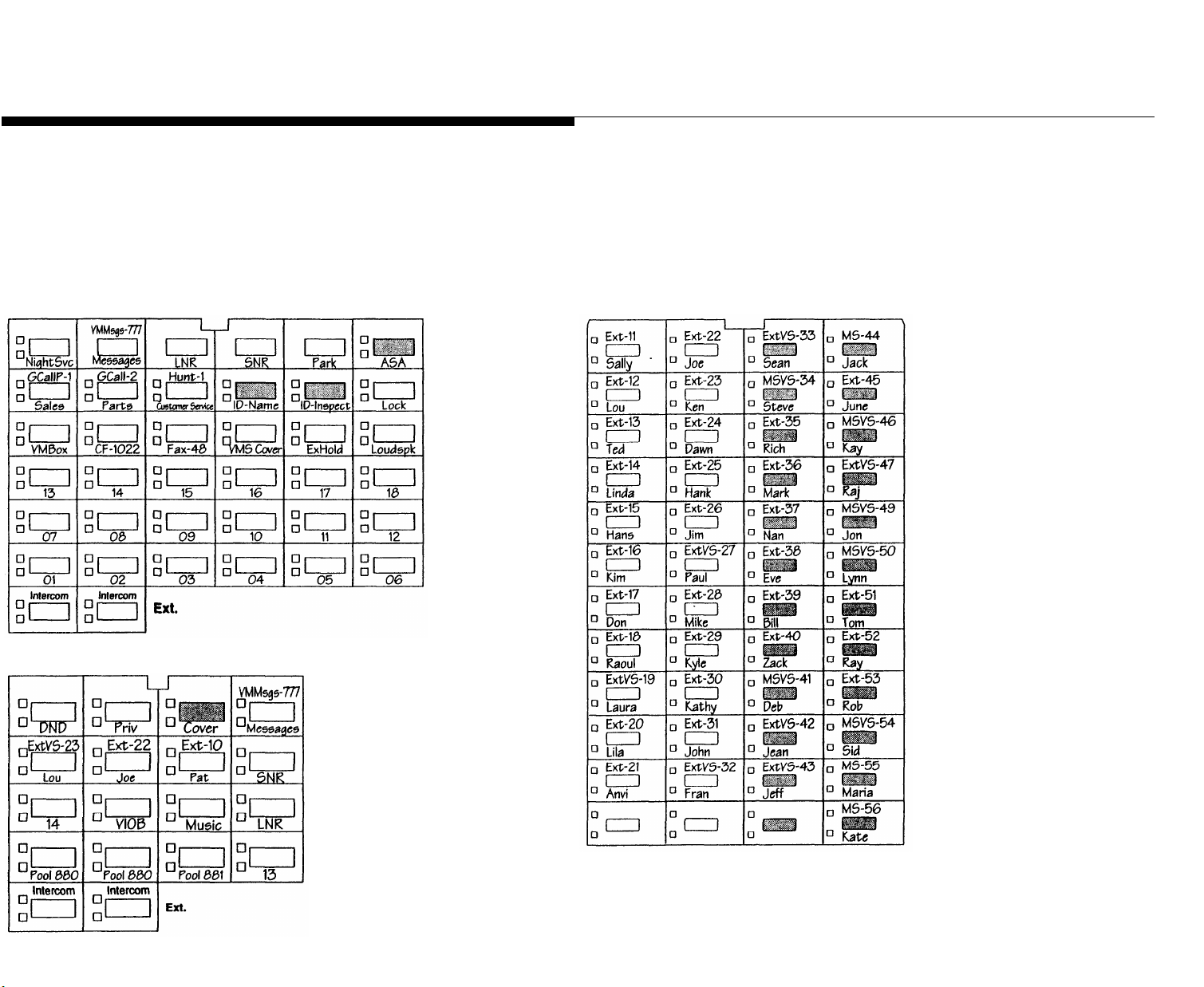
Example Templates
These examples show a PARTNER-34D telephone, PARTNER-CA48 Intercom
Autodialer programmed for a PARTNER II system receptionist, and a
PARTNER-18 telephone programmed for a PARTNER II system in Hybrid mode
for a user at a pooled extension. Buttons that are not used for lines or pools have
dial-code features. (The abbreviations are explained in "Button Feature
Summary" beginning on page 11.) The 34-button telephone has 18 lines
PARTNER-34D Telephone
assigned, and the Intercom Autodialer is programmed with Intercom Auto Dial
and Manual Signaling buttons for 45 extensions; the order of extensions has been
changed to begin with extension 11 on the top left button. The user’s 18-button
telephone has the main pool, an auxiliary pool, and 2 individual lines assigned; the
other 11 buttons are used for Intercom Auto Dialing and dial-code features.
NOTE:
system.
PARTNER-CA48 Intercom Autodialer
Shaded areas indicate features that are available only on a PARTNER II
PARTNER-18 Telephone
Page 13

Button Feature Summary
This section lists button features in order by feature type and feature name.
For each feature, the first line shows the following information:
■
The name of the feature.
■
Whether a button with lights is required ( ) or recommended ( ).
■
An abbreviation that can be entered on the Form C templates.
■
The entries needed to program the feature on a button. Some features can
include a two-digit extension number (shown as xx) or a single-digit group
number (shown as g).
Wake Up Service Button
Wake
{#115}
Allows the user at extension 10 to schedule an intercom call to a target extension at a
designated time. If Music on Hold {#602} is active, music is played when the phone is
answered; otherwise, nothing is heard.
Auto Dialing Features
Auto Dial numbers can include the digits
Hold
that you store by pressing
Transfr (Touch-tone Enable). To store an intercom number, you must press the
Intercom button before entering the extension number. Only one Auto Dial
left
(Pause),
number for an extension can be stored on the buttons available at an extension
for both the phone and Intercom Autodialer.
0 – 9 , ★ , # ,
Mic/HFAI
(Stop),
and special functions
Spkr
(Recall), and
Extension 10 Features
These features can be assigned only to the phone at extension 10. Auto dialing
and dial-code features can also be used at extension 10; of particular interest
are the Intercom Auto Dialing and Manual Signaling features, which use button
lights to show extension calling activity.
Automatic System Answer Button
(PARTNER II system only) Turns Automatic System Answer on and off. When the
feature is on, a call that is not answered by the receptionist is answered by the
system; the system plays a brief message, then places the call on hold, continues to
ring all extensions that have the line, or disconnects the call. To use Automatic
System Answer, extension 10 must be programmed with an ASA button.
Direct Extension Dial Button
(PARTNER II system only) Turns Direct Extension Dial on and off. When the feature
is on, a call that is not answered by the receptionist is answered by the system; the
system plays a brief message, then lets the caller dial an extension number or wait
for the receptionist. To use Direct Extension Dialing, extension 10 must be
programmed with a DXD button.
Night Service Button
Turns Night Service on and off. Phones in the Night Service Group ring immediately
when the feature is active, regardless of normal ringing. To use Night Service,
extension 10 must be programmed with a Night Service button. Night Service Group
extensions should be identified on Form B2.
Outgoing Call Restriction Button
Allows the user at extension 10 to change the outgoing call restriction for a particular
extension. An Auto Dial button with lights must be programmed for each extension to
be changed.
ASA {#111}
DXD
NightSvc
OCR
{#113}
{#503}
{#114}
Auto Dialing (Outside Phone Number)
xxx-xxxx
Places a call to an outside telephone number. Outside telephone numbers can be
up to 28 digits. If a dial-out code is required to dial outside numbers (for example, on
PBX or Centrex lines), include it in the stored number followed by pauses, if
necessary.
Auto Dialing (PBX/Centrex Feature Code)
xxx (NAME)
Dials a PBX/Centrex feature code. To program the button so the user can access
the feature while on a call, specify "R" on Form C before the feature code, and
include the Recall signal on the Auto Dial button.
Fax-
Fax Management
xx
Intercom
xx
Transfers calls to the fax machine at the designated extension with one touch. If on
a button with lights, the lights show when the fax is busy or when it is having trouble
and not answering—for example, when it is out of paper.
Intercom Auto Dialing—Ring
Ext-
Intercom
xx
xx
Places a ringing intercom call to an extension, or transfers a call. If on a button with
lights, the lights show calling activity at the destination extension.
Intercom Auto Dialing—Voice Signal
ExtVS-
xx
Intercom
★
xx
Places a voice-signaled intercom call to the extension’s phone speaker, or transfers
a call with a voice-signaled announcement. If on a button with lights, the lights show
calling activity at the destination extension.
11
Page 14

12
Manual Signaling—Ring
Beeps the designated extension. If the user presses
MS-
Intercom
xx
Feat
first, pressing the button
1 3
xx
places a ringing intercom call to the extension, or transfers a call. If on a button with
lights, the lights show calling activity at the destination extension.
Manual Signaling—Voice Signal
Beeps the designated extension. If the user presses
MSVS-
Intercom
xx
Feat
first, pressing the button
1 3 ★
xx
places a voice-signaled intercom call to the extension, or transfers a call with a
voice-signaled announcement. If on a button with lights, the lights show calling
activity at the destination extension.
Dial-Code Features
Account Code Entry ACE
Allows the user to enter an account code for a call by pressing the button, entering
up to 16 digits for the account code, then pressing the button again. If on a button
with lights, the lights show when the feature is in use.
Background Music Music
Turns background music on and off at the speaker of an idle system phone. If on a
button with lights, the lights show when the feature is in use.
Call Coverage
Cover-
xx xx
(PARTNER II system only) Directs all intercom, transferred, and outside calls on
lines assigned ownership to the designated extension. You may program originating
and covering extension numbers on the button. If on a button with lights, the lights
show when the feature is in use.
Call Forwarding/Call Follow-me CF-
xx xx
Forwards all calls to the designated extension. Unless Do Not Disturb is on, phone
beeps once each time a call is forwarded. You may program originating and
destination extension numbers on the button. If on a button with lights, the lights
show when the feature is in use.
Call Park
Park
Parks a call at a specific extension so it can be picked up from any other extension.
Call Pickup
Pickup-
Picks up a ringing or parked call at the designated extension.
Caller ID Inspect
lD-Inspect
(PARTNER II system only) When a user at a display phone is already on a call, this
feature shows Caller ID information for another line (if Caller ID information is
available on that line), without disconnecting the current call or putting it on hold.
When the feature is active, the button light is on.
xx
Feat
Feat
Feat
Feat
Intercom
Intercom
Feat
1 2
1 9
2 0
1 1
xx
6
1 7
xx xx
xx xx
xx
Caller ID Name Display
ID-Name
Feat
1 6
(PARTNER II system only) When a user at a display phone is on a call on a line that
has Caller ID information available, this feature lets the user switch between the
caller’s telephone number (the default display) and the caller’s name (if available).
When the feature is active—indicating that the caller’s name should be displayed—
the button light is on.
Conference Drop
Drop
Feat
0 6
Drops the last outside party added to a conference call.
Direct Line Pickup—Active Line
DLPA
Intercom
6 8
Allows the user to access a ringing, active, or held call on a line that is not assigned
to the extension. Direct Line Pickup is subject to Line Access Restrictions
programmed for the extension.
Direct Line Pickup—Idle Line
DLPI
Intercom
8
Allows the user to access an idle (non-busy) line that is not assigned to the
extension. Direct Line Pickup is subject to Line Access Restrictions programmed for
the extension.
Do Not Disturb
DND
Feat
0 1
Prevents calls from ringing at the extension. When the feature is active, the button
light is on. Intercom calls get a busy signal, and outside callers hear ringing. Use
only if someone else answers the extension’s outside calls.
If VMS Cover and Do Not Disturb are both active, intercom, transferred, and outside
calls on owned lines go directly to the extension’s voice mailbox. If Call Coverage
and Do Not Disturb are both active, intercom, transferred, and outside calls on lines
assigned ownership go directly to the covering extension.
Exclusive Hold
ExHold
Feat
0 2
Places a call on hold and prevents other extensions with the line from picking it up.
Group Calling—Page
GCallP-
g
Intercom
★ 7
g
Places a voice-signaled intercom call to all extensions in the designated Calling
Group (no transfer capability). The caller is connected to the first extension that
answers. g = 1–4
g
Group Calling—Ring
GCall-
Intercom
7
g
Places a ringing intercom call to all extensions in the designated Calling Group. The
caller is connected to the first extension that answers. Also can be used to transfer
a call to an extension in the group. g = 1–4
Page 15

g
Group Hunting—Ring
Hunt-
Intercom
7 7
g
Rings the first available extension in the designated Hunt Group, or transfers a call
to an extension in the group. If unanswered after 3 rings, the call moves to the next
available extension, and so on, until the call is answered or until the caller hangs up.
g = 1–6
Group Hunting—Voice Signal
HuntVS-
g
Intercom
★ 7 7
g
Voice signals the first available extension in the designated Hunt Group, or transfers
a call to the extension with a voice-signaled announcement. The caller is connected
only if that extension answers. g = 1–6
Group Pickup
P/U Grp-
g
Intercom
6 6
g
Picks up an intercom, transferred, or outside call ringing at any extension in the
designated Pickup Group. g = 1–4
Last Number Redial
LNR
Feat
0 5
Automatically redials the last outside number dialed up to a maximum of 28 digits.
This feature can be used to redial only the last outside number dialed.
Loudspeaker Paging
Loudspk
Intercom
7 0
Connects the user to the loudspeaker paging system, if one is connected to the
system.
Message Light Off
MsgOff-
xx
Feat
1 0
xx
Turns off the message light on the phone at the designated extension. You may also
program an extension number on the button.
Message Light On MsgOn-
xx
Feat
0 9
xx
Turns on the message light on the phone at the designated extension. You may also
program an extension number on the button.
Privacy
Priv
Feat
0 7
Prevents other people with the same line; from joining calls being conducted at this
extension. When the feature is active, the button light is on. This feature overrides
Automatic Extension Privacy {#304}.
Recall
Recall
Feat
0 3
"Recalls" a dial tone to access a PBX/Centrex feature while on a call on a PBX/
Centrex line (pressing Recall disconnects an intercom call).
Save Number Redial
SNR
Feat
0 4
This feature can be programmed onto more than one button. Using this feature
while on an outside call saves the number dialed into temporary memory. The
number stays in memory until a different one is saved; this feature can be used
again to redial the number at any time. (Unlike Last Number Redial, the user must
use this feature to save the number as well as to redial it; Save Number Redial lets
the user make other outside calls before redialing the saved number.) Account
codes cannot be saved and redialed using this feature.
Simultaneous Paging
SPage
I
ntercom
★ 7 0
Accesses the loudspeaker paging system and all idle system phones with speakers
assigned to Calling Group 1.
Station Lock
Lock
Feat
2 1
Lets the user lock the extension by entering a code of four digits (0-9) on the
telephone dialpad.
Touch-Tone Enable
TT-EN
Feat
0 8
Lets user with rotary lines access phone services that require touch-tone digits. For
example, after calling a bank-by-phone service and being prompted to enter touch-
tone digits, using this feature changes the digits dialed to touch tones for the rest of
the call.
VMS Cover
VMSCover
Feat
1 5
Turns voice mail coverage for the extension on and off if PARTNER MAIL or
PARTNER MAIL VS is installed. When the feature is active, the button light is on.
This feature overrides Automatic VMS Cover.
Voice Interrupt on Busy Talk-Back
VIOB
Feat
1 8
Lets user respond to voice interrupt on busy call while still active on the existing call.
Voice Mail Messages
VMMsdgs-777
Intercom
7 7 7
Places an intercom call to the PARTNER MAIL or PARTNER MAIL VS system
(if available), so the user can check messages, send messages, or administer
greetings.
Voice Mailbox Transfer
VMBox
Feat
1 4
Transfers a caller directly to a specific extension’s voice mailbox, so that the caller
can leave a message without having to first ring the extension.
13
Page 16

Form D Supplemental Instructions: Number Lists
14
Use this form to specify lists of Disallowed, Allowed, and Emergency telephone
numbers. Also use this form to identify the phone numbers dialed automatically
by External Hotlines.
NOTE: To restrict long-distance calling, Toll Call Prefix {#402} (indicating
whether you must dial a 0 or 1 to place long distance calls) must be set correctly (see Form A, Item 9).
Creating Disallowed and Allowed Lists
You can create up to 4 lists each of Disallowed and Allowed telephone numbers. Each list can have up to 10 numbers.
1.
Under the List number, write a name for the list (for example, "Suppliers").
2.
In the "Telephone Number" column, write the entries for the list. You can
specify complete telephone numbers or categories of numbers.
■
To specify a complete number, write it exactly as it would be dialed,
including (if needed) a dial-out code, toll call prefix, and area code.
■
To specify a category, provide one or more entries to describe an entire
class of calls (such as an area code or local exchange). Preventing calls
to a category may require more than one entry, to allow for different ways
of dialing a number (see "Examples of Disallowed List Entries").
After a list has been created, it can be assigned to an extension (see Form B2).
Disallowed Phone Number Lists {#404}
With Disallowed lists, you can prevent users from dialing specific telephone
numbers or categories (for example, calls to 976 exchanges for pre-recorded
messages such as horoscopes, and calls to 900 area code "chat lines").
Examples of Disallowed List Entries
Preventing Calls to 976 Exchange Numbers
Entries needed. . .
Preventing Calls to 900 Area Code
Entries needed. . .
Preventing International (011) Calls
Entry needed. . .
Preventing Long Distance Calls After Using a Local Telephone
Company Feature Consisting of a
Blocking ★ 67.
Entries needed. . .
if 0 or 1 toll prefix
is required is not required
976
0976
1976
1!!!976
0!!!976
if 0 or 1 toll prefix
is required
0900
1900
011
★ and Two Digits, Such as Call
*!!0
*!!1
if 0 or 1 toll prefix
976
!0!976
!1!976
if 0 or 1 toll prefix
is not required
900
Allowed Phone Number Lists {#407}
Allowed telephone numbers are exceptions to restrictions. For example, you might
put 976 numbers on a Disallowed list, but allow dialing of 976-1212 for weather
reports. Or you might restrict an extension to local dialing only, but assign an
Allowed list to permit the user to call specific customers or suppliers.
Page 17

Emergency Phone Number List {#406}
You can create a list of emergency numbers that can be dialed at any time by
any extension that has access to an outside line. The list can have up to 10
entries. Emergency numbers override all other dialing restrictions, including
Night Service with a System Password.
NOTE: Various factors influence the effectiveness of dialing restrictions. Avoid
putting 800 numbers in your Emergency Phone Number List. If you need to
allow restricted users to access 800 numbers, put those numbers in an Allowed Phone Number List instead.
Important Notices
■
Consult your local phone directory to determine the numbers for police, fire,
and ambulance service, because "911" is not available everywhere.
■
When programming emergency numbers and/or making test calls to
emergency numbers:
1.
Stay on the line and briefly explain to the dispatcher the reason for the
call before hanging up.
2.
Perform such activities during off-peak hours, such as in the early
morning or late evening.
Example Emergency List
911
611
(local phone company service)
555-2345
555-4567
555-1357
(Boss’s home)
(auto club)
(company doctor)
External Hotline {#311}
For each extension that has been designated as an External Hotline on Form B1,
write the telephone number that is dialed automatically when the handset is lifted.
Forced Account Code List {#409}
If an extension has been designated for Forced Account Code Entry {#307} on
Form B2, the user must dial an account code before an outside telephone
number can be dialed. Account codes, each up to 16 digits in length, can be
used to associate telephone calls with a particular department or client. Account
codes print on SMDR call reports and on reports generated by call accounting
packages.
If Forced Account Code Verification is desired, entries must be made in the
Forced Account Code List {#409}. When the system verifies an account code, it
compares only the first six digits of the user-entered account code to the entries
in the Forced Account Code List. For a match to be successful, the user must
dial at least the account code’s associated list entry, even though the user can
dial up to 16 digits for an account code. Wildcard entries are allowed on this list.
15
Page 18

Form E Supplemental Instructions:
System Speed Dial Numbers
16
With System Speed Dialing, a user can dial a stored number by pressing four
buttons: the
Feat
button
( #
on a standard phone) followed by a 3-digit code.
Storing a telephone number as a Speed Dial number lets users dial more
quickly. Other kinds of numbers—such as account codes and other dialing
sequences—also can be stored as Speed Dial numbers.
The system allows up to 100 System Speed Dial numbers that everyone on the
system can use, as well as up to 20 Personal Speed Dial numbers for each
extension (for the personal use of the extension user). Users should record
their Personal Speed Dial numbers on their Quick Reference card.
Please have the System Speed Dial Numbers form filled out when the
technician arrives to install the system. After installation, photocopy this form
and distribute a copy to everyone using the system. Users should keep this
form near their phones for reference when placing calls.
General Guidelines
Each System Speed Dial number is assigned a 3-digit code from 600-699.
For example, suppose employees frequently call Acme Supplies and Acme’s
telephone number is stored for code 620. To call Acme, a user simply dials
Feat
6 2 0 .
telephone number and users still dial
Record the following information for each System Speed Dial number:
Name/Company
Write the name of the person or company to which the number belongs. For
other types of numbers, such as account codes, enter a description of the
number.
★
Column (Marked System Speed Dial Numbers)
If users should be able to call a particular System Speed Dial number,
regardless of any dialing restrictions placed on their extensions, "mark" the
number so it can be dialed at all times. Mark the number by placing a check
mark in this column, and by pressing
If Acme moves, or the phone number changesf program the new
Feat
6 2 0
★
before the number when storing it.
to reach Acme.
Telephone Number
Write the number exactly as it should be dialed. Numbers can be up to 28
digits, including the digits
0 – 9 , ★ , # ,
and the special dialing functions
discussed next. To store a telephone number, include the dial-out code,
toll-call prefix, and area code (if needed), along with the number.
Special Dialing Functions
Function
Button to Press
Pause
Recall
Stop
Touch-Tone Enable
Hold
Spkr
Mic/HAFI
Transfr
Display Description
P Pauses for 1.5 seconds
before dialing the rest of the
stored number
R
Sends a timed switchhook
flash (useful for your
telephone company’s
custom calling features)
S
Interrupts the dialing
sequence until the code is
dialed again
T
Sends touch tones on a
rotary line
For marked numbers, the stored number does not appear on a display
phone when a user dials the Speed Dial code. Account codes cannot be
marked.
Page 19
Lucent Technologies
Bell Labs Innovations
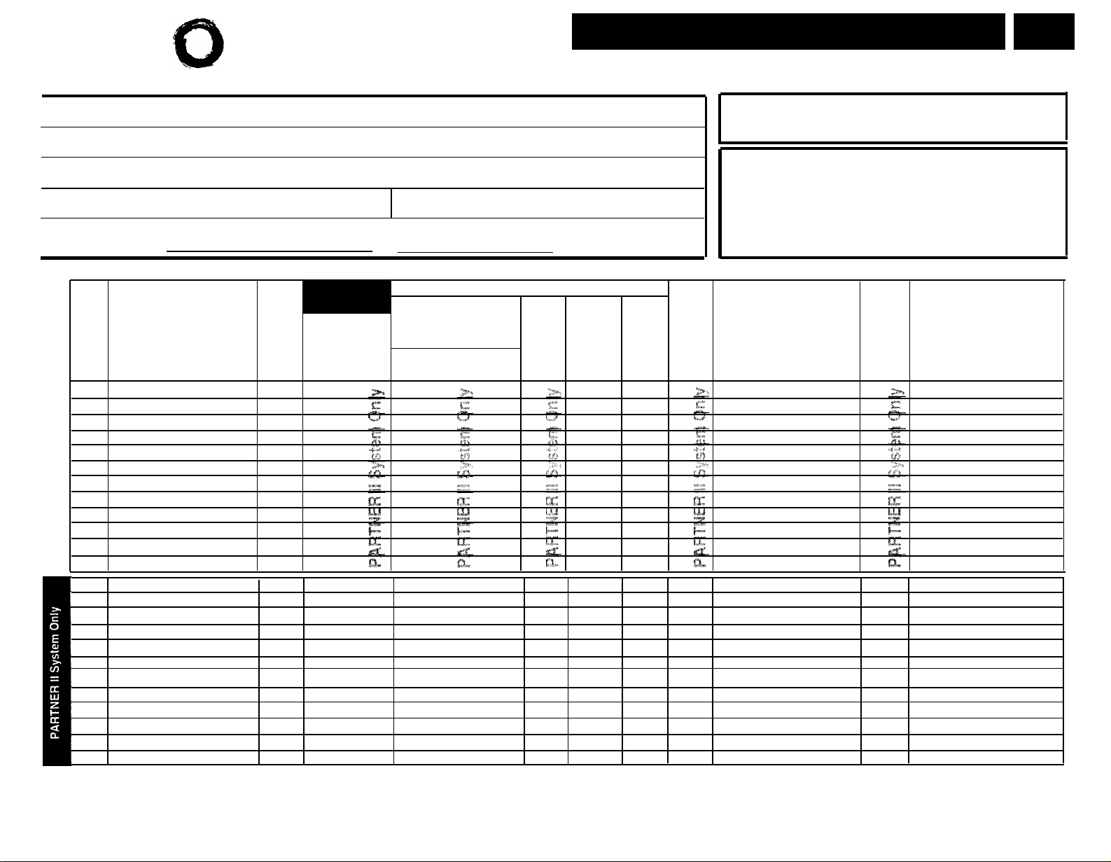
Form A: System Configuration
Required for PARTNER II System and PARTNER Plus System.
For additional instructions, see page 2.
PAGE
1 of 3
1. Customer Billing Name
2. Installation Address
3. Contact Name
Phone
() –
4. Person to be Trained
❑
5. Sold by
AT&T Sales Force
❑
Dealer:
Phone
() –
Alternate Trainee’s Name
Salesperson’s Name
Phone
() –
Phone
() –
8. System Lines
Line Coverage—You can select one per line
I l
l
DXD
l
l
l
l l
2
1
AA
{#607} {#205} {#206}
l
l
l
l
3
VMS-
AA
{#204} (write no.)
ASA
4
Only one of these
types per system
l
l
l
l
l
l
l
l
l
l
l
l
l
l
l
l
l
l
l
l
l
l
l
l
l
l
l
l
l
l
l
l
l
l
l
l
l
l
l
l
l
l
l
l
l
l
l
l
l
l
l
l
l
l
l
l
l
l
l
l
l
l
l
l
l
l
l
l
l
l
l
l
l
l
l
l
l
l
l
l
5. Write group number (1–6) covering this line. Also see Form B2, Hunt Group Extensions {#505} 1–6.
6. Check desired line for #206 or enter line owner’s extension number for #208. Also see Form B1, PARTNER
7. Write extension number of line owner eligible for Call Coverage. Also write line owner’s name in next
Line
Write the Telephone
Numbers in order
Jack
No.
customer desires
(list personal and
dedicated lines last)
Write
R if
Rotary
(Dial
Pulse)
Line
{#201} {#207}
Hybrid Mode
Only:
Write auxiliary
pool 881, 882,
883 or No Pool
01
02
03
04
05
06
07
08
09
10
11
12
13
14
15
16
17
18
19
20
21
22
23
24
1. Check if desired. Also see Form B1, AA Extension {#607} column.
2. Check if desired. Also see Form A, Item 10—DXD, and Form C, Direct Extension Dial Button {#113}.
3. Check if desired. Also see Form A, Item 10—VMS-AA, and Form B1, PARTNER MAIL or PARTNER MAIL VS
column.
4. Check if desired. Also see Form A, Item 10—ASA, and Form C, Automatic System Answer Button {#111}.
6. Configure Hardware for Hybrid Mode (PARTNER II system only):
7. Features Customer is most interested in (most important first):
Hunt
Group
{#206}
5
6
VMS-
Ext. No.
Mail
{#206}
or Cover
Write
for Call
7
Write User’s Name for
Personal or Owned Line
or Identify Equipment for
Dedicated Line
{#208} {#208}
MAIL or PARTNER MAIL VS column.
column.
No
❑
Yes
❑
If yes, call local telephone company—
MF Mode and FCC # AS5 USA-21312-MF-E
Check
if
Caller
ID
Identify other Local
Telephone Company
Subscription Services
(e.g., Repeat Call)
Service
Page 20

Lucent Technologies
Bell Labs Innovations
Form A: System Configuration
Required for PARTNER II System and PARTNER Plus System.
For additional instructions, see page 3.
PAGE
2 of 3
9.
System Settings. Write response on line for each item.
●
Receptionist answers calls during business hours? Write "Yes" or "No"
●
Number of Lines {#104}—By default, 2 lines per 206 module and 4 lines per 400 module
.
are assigned to each extension (or to pool 880 in PARTNER II Hybrid Mode). Write
number if different from default
Transfer Return Rings {#105}—By default, a transferred call rings 4 times before going to
●
.
the transfer return extension. Write number (0-9, 0 = no return) if different from
default
●
Outside Conference Denial {#109}—By default, a conference call can include 2 outside
parties. Write "No" if 2 outside parties are not allowed
●
Call Coverage Rings {#116} (PARTNER II only)—By default, a covered call rings 2 times
.
.
before going to the covering extention. Write number (1-9) if different from default
●
VMS Cover Rings {#117}—By default, a call rings 3 times before going to the user’s
mailbox. Write number (1-9) if different from default
●
Ring on Transfer {#119}—By default, the caller hears ringing when the call is transferred.
Write "NA" if music on hold or silence is desired
●
Toll Call Prefix {#402}—By default, 0 or 1 must be dialed before the area code for a
long distance call. Write "No" if 0 or 1 is not required
●
System Password {#403}—By default, no password is programmed to override dialing
.
.
.
restrictions and to turn Night Service on and off. Write 4 digits if password is
desired __ __ __ __.
●
Music on Hold {#602}—By default, the Music on Hold jack on the processor module is
active. Write "No" if the jack is deactivated
10.
Line Coverage. Complete items based on Line Coverage selection on Form A, Item 8.
DXD:
(PARTNER II system only) If DXD is checked, specify the following:
.
Direct Extension Dial Delay {#112}—By default, a call rings 2 times before it is
answered by the system. Write number (0-9) if different from default
Direct Extension Dial Record/Playback
(I
892)—message of up to 20 seconds that
.
caller hears when call is answered with the Direct Extension Dial feature. Write
message below and record from extension 10 or 11:
.
VMS-AA:
If VMS-AA is checked, specify the following:
VMS Hunt Delay {#506}—By default, VMS answers calls after 2 rings. Write "Del" if
calls ring 4 times before VMS answers
.
VMS Hunt Schedule {#507}—By default, VMS is on all the time. Check if Day only or
Night only is desired:
❑
Day only
❑
Night only
(PARTNER II system only) If ASA is checked, specify the following:
ASA:
Automatic System Answer Delay {#110}—By default, a call rings 2 times before it is
answered by the system. Write number (0-9) if different from default
.
Automatic System Answer Mode {#121}—By default, ASA calls are put on hold after the
greeting plays. Check if calls should continue to ring or be disconnected:
❑
Ring
❑
Disconnect
ASA Record/Playback
(I
891)—message of up to 10 seconds that caller hears
when the call is answered by the Automatic System Answer feature. Write
message below and record from extension 10 or 11:
Page 21
Lucent Technologies
Bell Labs Innovation
11.
Auxiliary Equipment (System). Check if applicable:
Battery Backup
❑
❑
Caller ID Devices
Loudspeaker Paging: Number of zones
❑
Magic on Hold (Music on Hold {#602} must be active.)
❑
Uninterruptible Power Supply
❑
SMDR If checked, specify the following if appropriate:
❑
●
SMDR Record Type (#608)—By default, all calls are included on call reports. Write
"Out" if only outgoing calls are reported
●
SMDR Output Format (#610)—By default, up to 15 digits are printed for dialed
numbers in the Number field of the call report. Write "24" if a maximum of 24 digits
is desired
●
SMDR Talk Time (#611) (PARTNER II only)—By default, a Talk field is not included
on the call report. Write "Active" if the Talk field is desired
12.
Notes: Write any additional information that you want to communicate to the installer.
Form A: System Configuration
PAGE
3 of 3
Required for PARTNER II System and PARTNER Plus System.
For additional instructions, see page 4.
.
.
.
13. Installation Date
14. Order Nos.
15. Sales Support Representative's Name
Telephone No.
Page 22
Lucent Technologies
Bell Labs Innovations.
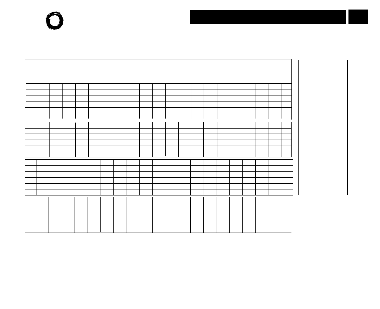
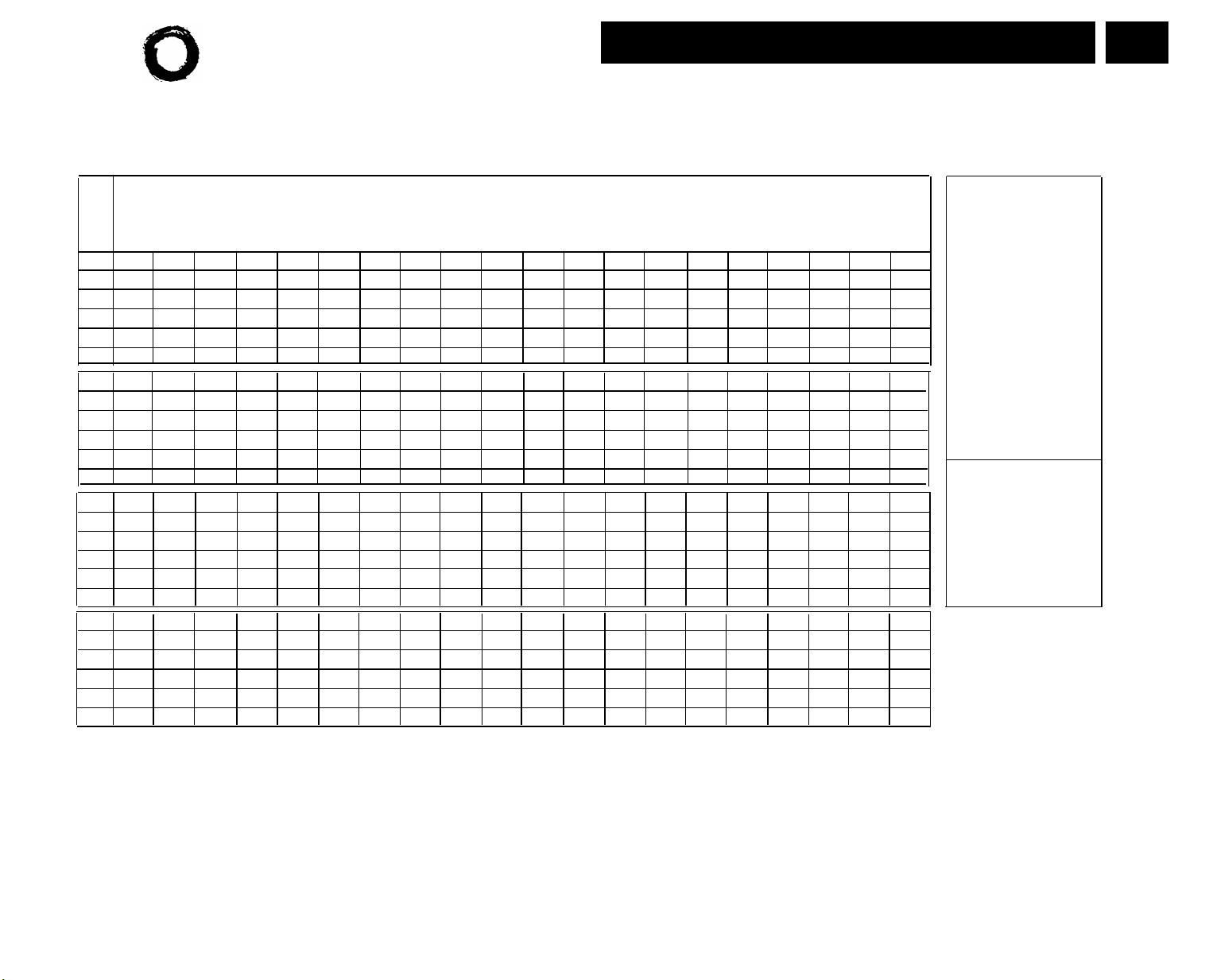
Form B1: System Extensions
Required for PARTNER II System and PARTNER Plus System.
For additional instructions, see page 5.
PAGE
1 of 4
Identify Auxiliary Equipment
Attatch to this Extension
l
l
l
l
l
l
l
l
l
l
l
l
l
l
l
l
l
l
l
l
l
l
l
l
l
l
l
l
l
l
l
l
l
l
l
l
l
l
l
l
l
l
l
l
l
l
l
l
l
l
l
l
l
l
l
l
l
l
l
l
l
l
l
l
l
l
l
l
l
l
l
l
l
l
l
l
l
l
Write in
Other
Equipment
Ext.
Jack
No.
10
11
12
13
14
15
16
17
18
19
20
21
22
23
24
25
26
27
28
29
30
31
32
33
Write Name/Description
l
l
l
l
l
l
l
l
l
l
l
l
l
l
l
l
l
l
l
l
l
l
l
l
l
l
l
l
l
l
l
l
l
l
l
l
l
l
l
l
l
Identify Telephone
Attached to this Extension
l
l
l
l
l
l
l
l
l
l
l
l
l
l
l
l
l
l
l
l
l
l
l
l
l
l
l
l
l
l
l
l
l
l
l
l
l
l
l
l
l
l
l
l
l
l
l
l
l
l
l
l
l
l
l
l
l
l
l
l
l
l
l
l
l
l
l
l
l
l
l
l
l
l
l
l
l
l
l
l
IMPORTANT: A system display phone is required for programming at extension 10 or 11. Extension 10 typically is the receptionist’s extension.
Extension 11 is recommended as a second programming extension (typically the System Manager’s extension).
1.
If checked, see Form B1, Page 3 of 4
If there is a mix of PARTNER-model and MLS-model phones, write “P” for PARTNER and “M” for MLS.
2.
Write “T” for touch-tone or “R” for rotaty. If Call Waiting is desired, check next column.
3.
Must be standard phone. If immediate dialing is required, use a dedicated line. Do not assign restrictions that
4.
prevent dialing the outside number, Forced Account Code Entry {#307}, or groups. Also see Form D, External Lines/Pools Not Assigned on Form B2.
Hotline {#311}.
Standard phone is recommended. Write extension number of corresponding alert extension or “70” for loud-
5.
speaker paging system in next column.
Also write Transfer Return Ext. No. {#306} on this form (usually extension 10). Also see Form B2, Identify
6.
Group Assignments, VMS Only.
To prevent other extensions from interrupting calls, assign Automatic Extension Privacy {#304} on Form B2.
7.
8.
Check corresponding alert extensions in next column. To prevent outside calls, remove all outside lines-see
9.
Also write Transfer Return Ext. No. {#306} on this form.
Write
Transfer
Return
Ext. No.
{#306}
Page 23
Lucent Technologies
Bell Labs Innovations
Form B1: System Extensions
Required for PARTNER II System extensions 34 through 57.
For additional instructions, see page 5.
PAGE
2 of 4
l
l
l
l
l
l
l
l
Ext.
Jack
No.
Write Name/Description
34
35
36
37
38
39
40
41
42
43
44
45
46
47
48
49
50
51
52
53
54
55
56
57
1.
If checked, see Form B1, Page 4 of 4
If there is a mix of PARTNER-model and MLS-model phones, write “P” for PARTNER and “M” for MLS.
2.
Write “T” for touch-tone or “R” for rotary. If Call Waiting is desired, check next column.
3.
Must be standard phone. If immediate dialing is required, use a dedicated line. Do not assign restrictions that
4.
prevent dialing the outside number, Forced Account Code Entry {#307}, or groups. Also see Form D, External
Hotline {#311}.
Standard phone is recommended. Write extension number of corresponding alert extension or “70” for loud-
5.
speaker paging system in next column.
l
l
l
l
l
l
l
l
l
l
l
l
l
l
l
l
l
l
l
l
l
l
l
l
l
l
l
l
l
l
l
l
l
Idenitify Telephone
Attached to this Extension
l
l
l
l
l
l
l
l
l
l
l
l
l
l
l
l
l
l
l
l
l
l
l
l
l
l
l
l
l
l
l
l
l
l
l
l
l
l
l
l
l
l
l
l
l
l
l
l
l
l
l
l
l
l
l
l
l
l
l
l
l
l
l
l
l
l
l
l
l
l
l
l
l
l
l
l
l
l
l
l
Also write Transfer Return Ext. No. {#306} on this form (usually extension 10). Also see Form B2, Identify
6.
Group Assignments, VMS Only.
To prevent other extensions from interrupting calls, assign Automatic Extension Privacy {#304} on Form B2.
7.
8.
Check corresponding alert extensions in next column. To prevent outside calls, remove all outside lines-see
Lines/Pools Not Assigned on Form B2.
Also write Transfer Return Ext. No. {#306} on this form.
9.
Identify Auxiliary Equipment
Attached to this Extension
l
l
l
l
l
l
l
l
l
l
l
l
l
l
l
l
l
l
l
l
l
l
l
l
l
l
l
l
l
l
l
l
l
l
l
l
l
l
l
l
l
l
l
l
l
l
l
l
l
l
l
l
l
l
l
l
l
l
l
l
l
l
l
l
l
l
l
l
l
l
l
l
l
l
l
l
l
l
Write in
Other
Equipment
Write
Transfer
Return
Ext. No.
{#306}
Page 24
Lucent Technologies
Bell Labs Innovations
Form B1: System Extensions
May be used if Ext. Name Display is checked on Form B1,
Page 1 of 4.
Character Codes
PAGE
3 of 4
Ext.
Jack
No.
10
11
12
13
14
15
16
17
18
19
20
21
22
23
24
25
26
27
28
29
30
31
32
33
Write 2-Digit Code for Each Character To Be Displayed — See Table at Right
Letters:
A = 21
B = 22
C = 23
D = 31
E = 32
F = 33
G = 41
H = 42
I = 43
J = 51
K = 52
L = 53
M = 61
Numbers:
blank = 11
0 = 00
1 = 10
2 = 20
3 = 30
4 = 40
N = 62
O = 63
P = 71
Q = 72
R = 73
S = 74
T = 81
U = 82
V = 83
W = 91
X = 92
Y = 93
Z = 94
5 = 50
6 = 60
7 = 70
8 = 80
9 = 90
Note: Only 12 characters display on MLS-model phones.
Page 25
Lucent Technologies
Bell Labs Innovations
Form B1: System Extensions
May be used if Ext. Name Display is checked on Form B1,
Page 2 of 4.
Character Codes
PAGE
4 of 4
Ext.
Jack
No.
34
35
36
37
38
39
40
41
42
43
44
45
46
47
48
49
50
51
52
53
54
55
56
57
Write 2-Digit Code for Each Character To Be Displayed — See Table at Right
Letters:
A
= 21
B
= 22
= 23
C
D
= 31
E
= 32
= 33
F
G
= 41
H
= 42
I
= 43
= 51
J
= 52
K
= 53
L
M
= 61
Numbers:
blank = 11
0 = 00 5 = 50
1 = 10 6 = 60
2 = 20 7 = 70
3 = 30 8 = 80
4 = 40
N
= 62
O
= 63
P
= 71
Q
= 72
R
= 73
S
= 74
T
= 81
U
= 82
V
= 83
W
= 91
X
= 92
Y
= 93
Z
= 94
9 = 90
Note: Only 12 characters display on MLS-model phones.
Page 26

Lucent Technologies
Bell Labs Innovations
Form B2: Customized Extension Settings
Required if you want to change extension settings from defaults for PARTNER II System
and PARTNER Plus System. For additional instructions, see pages 6 and 7.
PAGE
1 of 2
10
11
12
13
14
15
16
17
18
19
20
21
22
23
24
25
26
27
28
29
30
31
32
33
E ✔NA
✔
Identify Extension Settings
if Different than Default
A ✔NA
✔
A
✔
NA ✔NA
P
✔
✔
K ALL
Hybrid Mode
Only:
NA
✔
Identify Line Ringing {CTP} Option
If Different than Default
Write line numbers or pool access codes in each
column to show desired Line Ringing options
Immediate
✔
lines
Delayed
No Ring
✔
pools Not Assigned
Lines/Pools
Identify Restrictions/Permissions
If Different than Defaults
Write line numbers or pool access codes
for Line Access Restriction {#302} or
Pool Access Restriction {#315}
No Restriction ✔
3
Outgoing
only
Incoming
only
No Access
NR
Identify
Group Assignments
l
l
l
l
l
l
l
l
l
1–4
✔
1–4 1–4
NA
✔
1–4
✔
NA
l
1–6 7
NA
✔
l
l
l
l
l
l
l
l
l
l
l
l
l
l
l
l
l
l
l
l
l
NA
✔
Write S for Spanish or F for French.
1.
2.
In Hybrid Mode only, write K for Key extension. Extension 10 always operates
as a Key extension.
In Key Mode, use Line Assignment {#301} to remove lines from or assign lines
3.
to extensions. In Hybrid Mode, use Pool Extension Assignment {#314} to
remove pools from or assign pools to extensions.
4.
Write IN for Inside Only or LOC for Local Only to indicate restrictions for all
outgoing calls on all lines.
5.
Write list number (1–4). Also see Form D, Disallowed Phone Number Lists {#404}.
Write list number (1–4). Also see Form D, Allowed Phone Number Lists {#407}.
6.
Write group number (1–4).
7.
8.
Write group number (1 –4). If a loudspeaker is connected and Simultaneous Paging is desired,
put appropriate extensions in Calling Group 1. Also see Form C, Simultaneous Paging.
Write group number (1–6).
9.
10.
Check off the same PARTNER MAIL or PARTNER MAIL VS extensions indicated on Form B1.
Assignments
✔
= Default
A
= Assigned or Active
E
= English
NA
= Not Assigned or Not Active
NR
= No Restriction
P
= Pooled
{CTP}
= Centralized Telephone Programming
Page 27

Lucent Technologies
Bell Labs Innovations
Form B2: Customized Extension Settings
Required if you want to change extension settings from defaults for PARTNER II System
extensions 34 through 57. For additional instructions, see pages 6 and 7.
PAGE
2 of 2
34
35
36
37
38
39
40
41
42
43
44
45
46
47
48
49
50
51
52
53
54
55
56
57
Identify Extension Settings Identify
if Different than Default
Identify Line Ringing {CTP} Option
If Different than Default
Hybrid Mode
Only:
Write line numbers or pool access codes in each
column to show desired Line Ringing options
Write line numbers or pool access codes
for Line Access Restriction {#302} or
Pool Access Restiction {#315}
Immediate
✔
NA
NA
✔
✔
E
✔
✔
A
A
✔
NA ✔NA
✔
NA
P
✔
✔
lines
Delayed
No Ring Lines/Pools
✔
pools
Not Assigned
3
Outgoing
only
Identify Restrictions/Permissions
If Different than Defaults
No Restriction ✔
Incoming
only
No Access
NR
✔
1–4 1–4
NA
✔
Group Assignments
1–4
1–4 1–6
NA
✔
NA
l
l
l
l
l
l
l
l
l
7
l
NA
✔
✔
l
l
l
l
l
l
l
l
l
l
l
l
l
l
l
l
l
l
l
l
l
l
l
l
l
l
l
l
1.
Write S for Spanish or F for French.
In Hybrid Mode only, write K for Key extension.
2.
In Key Mode, use Line Assignment {#301} to remove lines from or assign lines 7.
3.
to extensions. In Hybrid Mode, use pool Extension Assignment {#314} to
remove pools from or assign pools to extensions.
Write IN for Inside Only or LOC for Local Only to indicate restrictions for all
4.
outgoing calls on all lines.
Write list number (1–4). Also see Form D, Disallowed Phone Number Lists {#404}.
5.
Write list number (1–4). Also see Form D, Allowed Phone Number Lists {#407}.
6.
Write group number (1–4).
Write group number (1–4). If a loudspeaker is connected and Simultaneous Paging is desired,
8.
put appropriate extensions in Calling Group 1. Also see Form C, Simultaneous Paging.
Write group number (1–6).
9.
Check off the same PARTNER MAIL or PARTNER MAIL VS extensions indicated on Form B1.
10.
Assignments
✔
= Default
A
= Assigned or Active
E
= English
= Not Assigned or Not Active
NA
NR
= No Restriction
P
= Pooled
{CTP}
= Centralized Telephone Programming
Page 28

Lucent Technologies
Bell Labs Innovations
Template Instructions
●
If desired, write in line number, pool access code, dial code feature, or auto dial number
●
If desired, write in Line Ringing (Imm, Del, or No) from Form B2
●
If desired, write in Line Access Restriction or Pool Access Restriction
(Out, In, or No) from Form B2
Intercom
Intercom
Ext.
* For PARTNER II systems in Hybrid mode only, if pool 880 is assigned, these two
buttons are associated with this pool.
Specify Automatic Line Selection:
Identify extensions programmed as shown:
Form C1: PARTNER-34D Phone
PAGE
1 of 8
Make as many copies as you need. Use template and/or checklist. For additional
instructions, see page 8.
Check Desired Features
Also write in extension or group number
SAMPLE
Automatic System Answer Button {#111}
Direct Extension Dial Button {#113}
Night Service Button {#503} NightSvc
Outgoing Call Restriction Button {#114)
Wake Up Service Button {#115}
Caller ID Inspect (F 17)
Caller ID Name Display (F 16)
1
1
Do Not Disturb (F 01)
Privacy (F 07) Priv
VMS Cover (F 15) VMSCover
Voice Interrupt on Busy Talk-Back (F 18)
Account Code Entry (F 12)
Background Music (F 19)
Call Coverage (F 20 XX XX)
3
3
1,3,5
Call Forwarding/Call Follow-Me (F 11 XX XX)
Call Park (I XX)
4
Call Pickup (I XX)
Conference Drop (F 06)
Direct Line Pickup-Active Line
Direct Line Pickup-Idle Line
(I
(I
8)
Exclusive Hold (F 02) ExHold
Fax Management (I XX)
Group Calling-Ring/Page
Group Hunt-Ring/Signal
Group Pickup
(I
3
(I
7 G or I *7 G) GCall-g
(I
77 G or I *77 G)
66 G) P/U Grp-g
Intercom Autodial (I XX or I *XX)
Last Number Redial (F 05)
Loudspeaker Paging
(I
70)
Manual Signaling (F 13 XX or F 13 *XX)
Message Light Off (F 10 XX)
Message Light On (F 09 XX)
6
6
Recall (F 03) Recall
Save Number Redial (F 04)
Simultaneous Paging
Station Lock (F 21)
(I
* 70) SPage
3
Touch-Tone Enable (F 08)
Voice Mail Messages Button
(I
777)
Voice Mailbox Transfer (F 14)
F = Feature button G = Group I = Left Intercom button XX= Extension
1
1
2
ASA
DXD
OCR
Wake
ID-Inspect
ID-Name
DND
VIOB
ACE
Music
Cover-XX XX
3,5
CF-XX XX
Park
Pickup-XX
Drop
68) DLPA
DLPI
FAX-XX
Hunt-g
3
Ext-XX
LNR
Loudspk
3
MS-XX
MsgOff-XX
MsgOn-XX
SNR
Lock
TT-EN
VMMsgs-777
VMBox
PARTNER
1.
II system
only.
2.
Requires
Auto Dial
button for
each
extension.
Button with
3.
lights is
recommended, but
not required.
Extension
4.
number can
be programmed
as Auto Dial
button.
You can
5.
program the
origination
extension
only or both
the
origination
and
destination
extension.
6.
You can
program the
extension
number.
Page 29

Lucent Technologies
Bell Labs Innovations
Form C2: Intercom Autodialer
For additional intructions,
see page 9.
PARTNER II only
PAGE
2 of 8
Template Instructions
●
If desired, write in intercom Ring (Ext-XX) or Voice Signal (ExtVS-XX),
or Manual Signal Ring (MS-XX) or Voice Signal (MSVS-XX)
●
If desired, write in user name for this extension
SAMPLE
Extensions programmed as shown (circle choices): 10 11
Page 30

Lucent Technologies
Bell Labs Innovations
Template Instructions
●
If desired, write in line number, pool access code, dial code feature, or auto dial number
●
If desired, write in Line Ringing (Imm, Del, or No) from Form B2
●
If desired, write in Line Access Restriction or Pool Access Restriction
(Out, In, or No) from Form B2
Intercom
Intercom
Ext.
* For PARTNER II systems in Hybrid mode only, if pool 880 is assigned, these two
buttons are associated with this pool.
Specify Automatic Line Selection:
Identify extensions programmed as shown:
Form C3: PARTNER-18 Phone
Make as many copies as you need. Use template and/or checklist.
For additional instructions, see page 8.
SAMPLE
PARTNER-18D only
Check Desired Features
Also write in extension or group number
Automatic System Answer Button {#111}
Direct Extension Dial Button {#113}
1
1
Night Service Button {#503}
Outgoing Call Restriction Button {#114}
2
WaKe Up Service Button {#115}
Caller ID Inspect (F 17)
Caller ID Name Display (F 16)
1
1
Do Not Disturb (F 01)
Privacy (F 07)
VMS Cover (F 15)
Voice Interrupt on Busy Talk-Back (F 18)
Account Code Entry (F 12)
Background Music (F 19)
Call Coverage (F 20 XX XX)
3
3
1,3,5
Call Forwarding/Call Follow-Me (F 11 XX XX)
(I
4
6 XX)
Call Park (I XX)
Call Pickup
Conference Drop (F 06)
Direct Line Pickup-Active Line
Direct Line Pickup-Idle Line
Exclusive Hold (F 02)
Fax Management (I XX)
Group CallingRing/Page
Group Hunt-Ring/Signal
Group Pickup
(I
66 G)
Intercom Autodial (I XX or I *XX)
(I
68)
(I
8)
3
(I
7 G or I *7 G)
(I
77 G or I *77 G)
3
Last Number Redial (F 05)
Loudspeaker Paging
Manual Signaling (F 13 XX or F 13 *XX)
Message Light Off (F 10 XX)
Message Light On (F 09 XX)
(I
70)
3
6
6
Recall (F 03)
Save Number Radial (F 04)
Simultaneous Paging
Station Lock (F 21)
(I
* 70)
3
Touch-Tone Enable (F 08)
Voice Mail Messages Button
(I
777)
Voice Mailbox Transfer (F 14)
F = Feature button G = Group I = Left Intercom button XX = Extension
ASA
DXD
NightSvc
OCR
Wake
ID-Inspect
lD-Name
DND
Priv
VMSCover
VIOB
ACE
Music
Cover-XX XX
3,5
CF-XX XX
Park
Pickup-XX
Drop
DLPA
DLPI
ExHold
FAX-XX
GCall-g
Hunt-g
P/U Grp-g
Ext-XX
LNR
Loudspk
MS-XX
MsgOff-XX
MsgOn-XX
Recall
SNR
SPage
Lock
TT-EN
VMMsgs-777
VMBox
1.
PARTNER
II system
only.
2.
Requires
Auto Dial
button for
each
extension.
3.
Button with
lights is
recommended, but
not required.
Extension
4.
number can
be programmed
as Auto Dial
button.
You can
5.
program the
origination
extension
only or both
the
origination
and
destination
extension.
You can
6.
program the
extension
number.
PAGE
3 of 8
Page 31

Lucent Technologies
Bell Labs Innovations
Template Instructions
●
If desired, write in line number, pool access code, dial code feature, or auto dial number
●
If desired, write in Line Ringing (Imm, Del, or No) from Form B2
●
If desired, write in Line Access Restriction or Pool Access Restriction
(Out, In, or No) from Form B2
Intercom
Intercom
Ext.
* For PARTNER II systems in Hybrid mode only, if pool 880 is assigned, these two
buttons are associated with this pool.
Form C4: PARTNER-6 Phone
Make as many copies as you need. Use template and/or checklist.
For additional instructions, see page 8.
Check Desired Features
SAMPLE
Also write in extension or group number
Do Not Disturb (F 10)
Privacy ( F 07)
VMS Cover (F 15)
Voice Interrupt on Busy Talk-Back (F 18)
Account Code Entry (F 12)
Background Music (F 19)
Call Coverage (F 20 XX XX)
1
1
✔
1,2,3
✔
Call Forwarding/Call Follow-Me (F 11 XX XX)
(I
4
6 XX)
Call Park (I XX)
Call Pickup
Conference Drop (F 06)
Direct Line Pickup-Active Line
Direct Line Pickup-Idle Line
(I
(I
8)
68)
Exclusive Hold (F 02)
66 G)
1
(I
7 G or I *7 G)
(I
77 G or I *77 G)
1
Fax Management (I XX)
Group Calling-Ring/Page
Group Hunt-Ring/Signal
Group Pickup
(I
Intercom Autodial (I XX or I *XX)
Last Number Redial (F 05)
Loudspeaker Paging
Manual Signaling (F 13 XX or F 13 *XX)
Message Light Off (F 10 XX)
Message Light On (F 09 XX)
(I
70)
5
5
Recall (F 03)
Save Number Redial (F 04)
Simultaneous Paging
Station Lock (F 21)
(I
* 70)
1
Touch-Tone Enable (F 08)
Voice Mail Messages
(I
777)
Voice Mailbox Transfer (F 14)
VMSCover
Cover-XX XX
1,3
CF-XX XX
1
MsgOff-XX
MsgOn-XX
VMMsgs-777
PAGE
4 of 8
DND
Priv
VIOB
ACE
Music
Park
Pickup-XX
Drop
DLPA
DLPI
ExHold
FAX-XX
GCall-g
Hunt-g
P/U Grp-g
Ext-XX
LNR
Loudspk
MS-XX
Recall
SNR
SPage
Lock
TT-EN
VMBox
Specify Automatic Line Selection:
Identify extensions programmed as shown:
F = Feature button G = Group I = Left Intercom button L = Line XX= Extension
Button with lights is recommended, but not required.
1.
PARTNER II system only.
2.
You can program the origination extension only or both the origination
3.
and destination extension.
Extension number can be programmed as Auto Dial button.
4.
You can program the extension number.
5.
Page 32
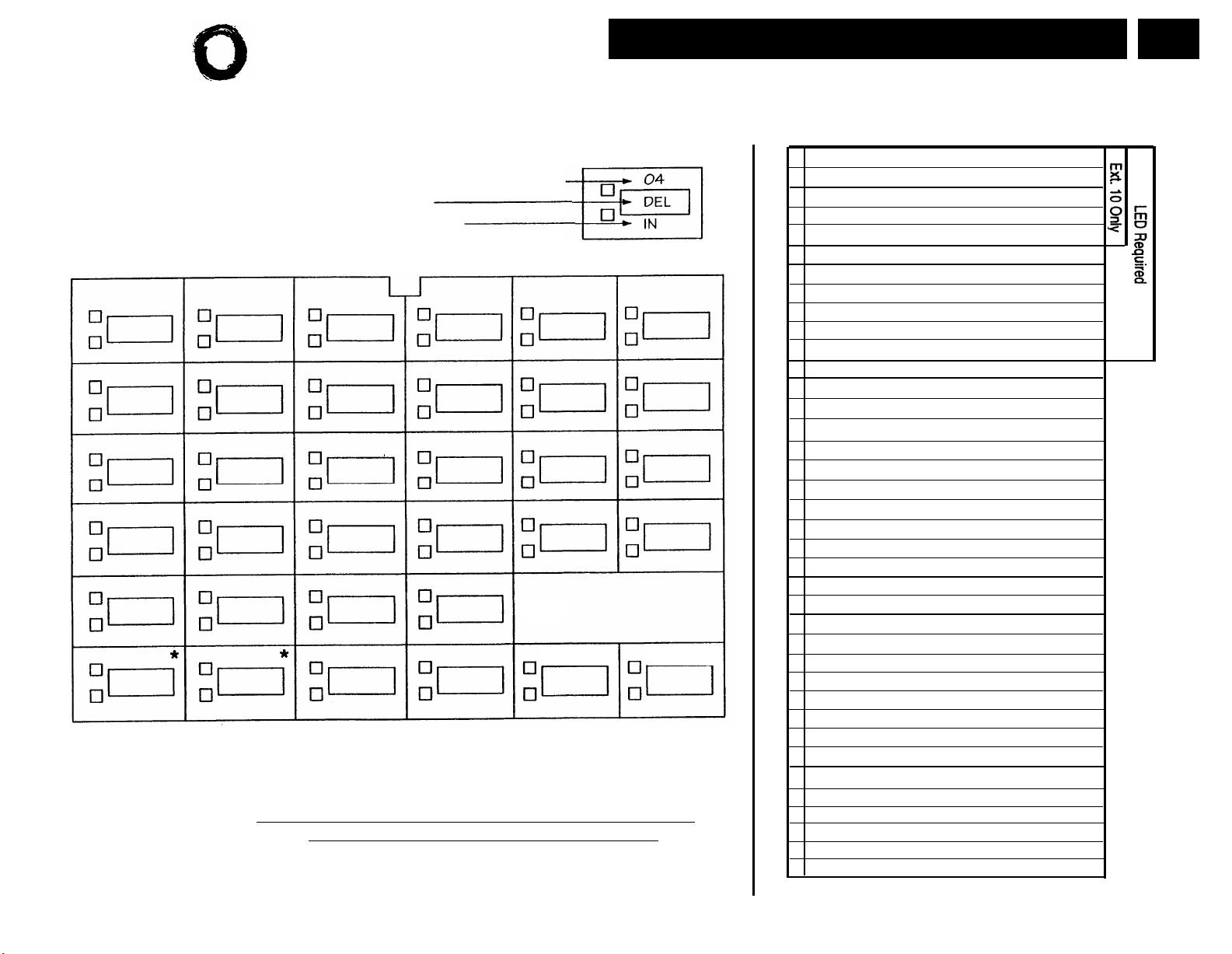
Lucent Technologies
Bell Labs Innovations
Template Instructions
●
If desired, write in line number, pool access code, dial code feature, or auto dial number
●
If desired, write in Line Ringing (Imm, Del, or No) from Form B2
●
If desired, write in Line Access Restriction or Pool Access Restriction
(Out, In, or No) from Form B2
Ext.
Intercom
* For PARTNER II systems in Hybrid mode only, if pool 880 is assigned, these two
buttons are associated with this pool.
Specify Automatic Line Selection:
Identify extensions programmed as shown:
Form C5: MLS-34D Phone
PAGE
5 of 8
Make as many copies as you need. Use template and/or checklist. For additional
instructions, see page 8.
Check Desired Features
Also write in extension or group number
SAMPLE
Intercom
Automatic System Answer Button {#111}
Direct Extension Dial Button {#113}
Night Service Button {#503} NightSvc
Outgoing Call Restriction Button {#114}
Wake Up Service Button {#115}
Caller ID Inspect (F 17)
Caller ID Name Display (F 16)
1
1
Do Not Disturb (F 01)
Privacy (F 07)
VMS Cover (F 15)
Voice Interrupt on Busy Talk-Back (F 18)
Account Code Entry (F 12)
Background Music (F 19)
Call Coverage (F 20 XX XX)
3
3
1,3,5
Call Forwarding/Call Follow-Me (F 11 XX XX)
(I
4
6 XX)
Call Park (I XX)
Call Pickup
Conference Drop (F 06) Drop
Direct Line Pickup-Active Line
Direct Line Pickup-Idle Line
(I
68)
(I
8) DLPI
Exclusive Hold (F 02) ExHold
66 G)
3
(I
7 G or I *7 G)
(I
77 G or I *77 G) Hunt-g
Fax Management (I XX)
Group Calling-Ring/Page
Group Hunt-Ring/Signal
Group Pickup
(I
Intercom Autodial (I XX or I *XX)
Last Number Redial (F 05)
Loudspeaker Paging
Manual Signaling (F 13 XX or F 13 *XX)
Message Light Off (F 10 XX)
Message Light On (F 09 XX)
(I
70)
6
6
Recall (F 03)
Save Number Redail (F 04)
Simultaneous Paging
Station Lock (F 21)
(I
* 70)
3
Touch-Tone Enable (F 08)
Voice Mail Messages Button
(I
777)
Voice Mailbox Transfer (F 14)
F = Feature button G = Group I = Left Intercom button XX = Extension
1
1
2
ASA
DXD
OCR
Wake
ID-Inspect
ID-Name
DND
Priv
VMSCover
VIOB
ACE
1.
Music
Cover-XX XX
3,5
CF-XX XX
Park
Pickup-XX
DLPA
FAX-XX
GCall-g
3
P/U Grp-g
Ext-XX
LNR
Loudspk
3
MS-XX
MsgOff-XX
MsgOn-XX
Recall
SNR
SPage
Lock
PARTNER
II system
only.
Requires
2.
Auto Dial
button for
each
extension.
3.
Button with
lights is
recommended, but
not required.
Extension
4.
number can
be programmed
as Auto Dial
button.
5.
You can
program the
origination
extension
only or both
the
origination
and
destination
extension.
6.
You can
program the
extension
number.
TT-EN
VMMsgs-777
VMBox
Page 33
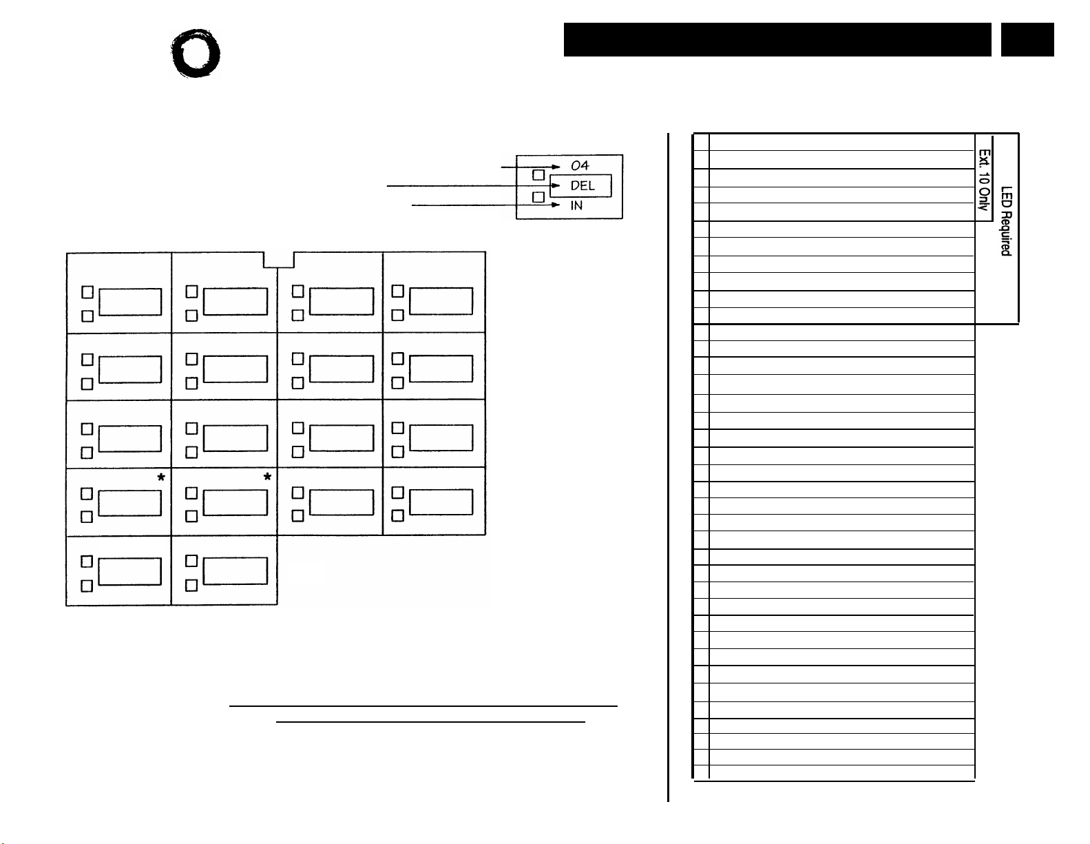
Lucent Technologies
Bell Labs Innovations
Template Instructions
●
If desired, write in line number, pool access code, dial code feature, or auto dial number
●
If desired, write in Line Ringing (Imm, Del, or No) from Form B2
●
If desired, write in Line Access Restriction or Pool Access Restriction
(Out, In, or No) from Form B2
Intercom
Intercom
Ext.
* For PARTNER II systems in Hybrid mode only, if pool 880 is assigned, these two
buttons are associated with this pool.
Specify Automatic Line Selection:
Identify extensions programmed as shown:
Form C6: MLS-18 Phone
Make as many copies as you need. Use template and/or checklist.
For additional instructions, see page 8.
Check Desired Features
SAMPLE
Also write in extension or group number
Automatic System Answer Button {#111}
Direct Extension Dial Button {#113}
Night Service Button {#503} NightSvc
Outgoing Call Restriction Button {#114}
Wake Up Service Button {#115}
Caller ID Inspect (F 17)
Caller ID Name Display (F 16)
Do Not Disturb (F 01)
Privacy (F 07)
VMS Cover (F 15) VMSCover
Voice Interrupt on Busy Talk-Back (F 18)
Account Code Entry (F 12)
Background Music (F 19)
Call Coverage (F 20 XX XX)
Call Forwarding/Call Follow-Me (F 11 XX XX)
Call Park (I XX)
Call Pickup
(I
6 XX) Pickup-XX
Conference Drop (F 06)
Direct Line Pickup-Active Line
Direct Line Pickup-Idle Line
Exclusive Hold (F 02) ExHold
Fax Management (I XX)
Group Calling-Ring/Page
Group Hunt-Ring/Signal
Group Pickup
(I
Intercom Autodial (I XX or I *XX)
Last Number Radial (F 05)
Loudspeaker Paging
Manual Signaling (F 13 XX or F 13 * XX)
Message Light Off (F 10 XX)
Message Light On (F 09 XX)
Recall (F03)
Save Number Radial (F 04)
Simultaneous Paging
Station Lock (F 21)
Touch-Tone Enable (F 08)
Voice Mail Messages Button
Voice Mailbox Transfer (F 14)
F= Feature button G = Group I = Left Intercom button XX = Extension
4
66 G)
1
1
3
3
1,3,5
(I
(I
8)
3
(I
7 G or I *7 G) GCall-g
(I
77 G or I *77 G)
(I
70)
6
6
(I
* 70)
3
(I
777) VMMsgs-777
1
1
2
Cover-XX XX
3,5
68)
3
3
MsgOff-XX
MsgOn-XX
ASA
DXD
OCR
Wake
lD-Inspect
ID-Name
DND
Priv
VIOB
ACE
Music
CF-XX XX
Park
Drop
DLPA
DLPI
FAX-XX
Hunt-g
P/U Grp-g
Ext-XX
LNR
Loudspk
MS-XX
Recall
SNR
SPage
Lock
TT-EN
VMBox
PAGE
6 of 8
PARTNER
1.
II system
only.
Requires
2.
Auto Dial
button for
each
extension.
3.
Button with
lights is
recommended, but
not required.
4.
Extension
number can
be pro-
grammed
as Auto Dial
button.
You can
5.
program the
origination
extension
only or both
the
origination
and
destination
extension.
You can
6.
program the
extension
number.
Page 34
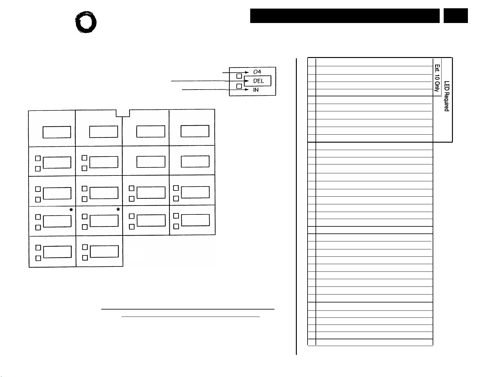
Lucent Technologies
Bell Labs Innovations
Template Instructions
●
If desired, write in line number, pool access code, dial code feature, or auto dial number
●
If desired, write in Line Ringing (Imm, Del, or No) from Form B2
●
If desired, write in Line Access Restriction or Pool Access Restriction
(Out, In, or No) from Form B2
Intercom
Intercom
Ext.
* For PARTNER II systems in Hybrid mode only, if pool 880 is assigned, these two
buttons are associated with this pool.
Specify Automatic Line Selection:
Identify extensions programmed as shown:
Form C7: MLS-12 Phone
Make as many copies as you need. Use template and/or checklist.
For additional instructions, see page 8.
Check Desired Features
SAMPLE
Also write in extension or group number
Automatic System Answer Button {#111}
Direct Extension Dial Button {#113)
Night Service Button {#503} NightSvc
Outgoing Call Restriction Button {#114}
Wake Up Service Button {#115}
Caller ID inspect (F 17)
Caller ID Name Display (F 16)
Do Not Disturb (F 01)
Privacy (F 07)
VMS Cover (F 15)
Voice Interrupt on Busy Talk-Back (F 18)
Account Code Entry (F 12)
Background Music (F 19)
Call Coverage (F 20 XX XX)
Call Forwarding/CalllFollow-Me (F 11 XX XX)
Call Park (I XX)
Call Pickup
(I
6 XX) Pickup-XX
Conference Drop (F 06)
Direct Line Pickup-Active Line
Direct Line Pickup-idle Line
Exclusive Hold (F 02) ExHold
Fax Management (I XX)
Group Calling-Ring/Page
Group Hunt-Ring/Signal
Group Pickup
(I
Intercom Autodial (I XX or I XX)
Last Number Redial (F 05)
Loudspeaker Paging
Manual Signaling (F 13 XX or F 13 *XX)
Message Light Off (F 10 XX)
Message Light On (F 09 XX)
Recall (F 03)
Save Number Redial (F 04) SNR
Simultaneous Paging
Station Lock (F 21)
Touch-Tone Enable (F 08)
Voice Mail Messages Button
Voice Mailbox Transfer (F 14)
F = Feature button G = Group I = Left Intercom button XX = Extension
4
66 G)
1
3
3
(I
3
(I
(I
77 G or I *77 G)
(I
70)
(I
* 70)
3
1
1,3,5
(I
8)
7 G or I *7 G)
6
6
(I
777)
1
1
2
Cover-XX XX
3,5
68) DLPA
3
3
VMMsgs-777
ASA
DXD
OCR
Wake
ID-Inspect
ID-Name
DND
Priv
VMSCover
VIOB
ACE
Music
CF-XX XX
Park
Drop
DLPI
FAX-XX
GCall-g
Hunt-g
P/U Grp-g
Ext-XX
LNR
Loudspk
MS-XX
MsgOff-XX
MsgOn-XX
Recall
SPage
Lock
TT-EN
VMBox
PAGE
7 of 8
PARTNER
1.
II system
only.
2.
Requires
Auto Dial
button for
each
extension.
3.
Button with
lights is
recommended, but
not required.
4.
Extension
number can
be programmed
as Auto Dial
button.
You can
5.
program the
origination
extension
only or both
the
origination
and
destination
extension.
6.
You can
program the
extension
number.
Page 35
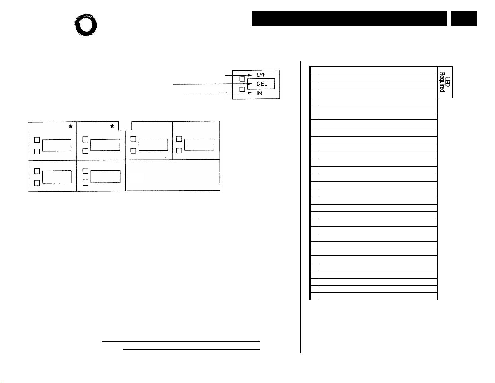
Lucent Technologies
Bell Labs Innovations
Template Instructions
●
If desired, write in line number, pool access code, dial code feature, or auto dial number
●
If desired, write in Line Ringing (Imm, Del, or No) from Form B2
●
If desired, write in Line Access Restriction or Pool Access Restriction
(Out, In, or No) from Form B2
Intercom
Intercom
Ext.
* For PARTNER II systems in Hybrid mode only, if pool 880 is assigned, these two
buttons are associated with this pool.
Form C8: MLS-6 Phone
Make as many copies as you need. Use template and/or checklist.
For additional instructions, see page 8.
Check Desired Features
SAMPLE
Also write in extension or group number
Do Not Disturb (F 01)
Privacy (F 07)
VMS Cover (F 15)
Voice Interrupt on Busy Talk-Back (F 18)
Account Code Entry (F 12)
1
Background Music (F 19)1 ✔ Music
Call Coverage (F 20 XX XX)
1,2,3
✔
Call Forwarding/Call Follow-Me (F 11 XX XX)
Call Park (I XX)
4
Call Pickup (I 6 XX)
Conference Drop (F 06)
Direct Line Pickup-Active Line
Direct Line Pickup-Idle Line
(I
(I
8)
68)
Exclusive Hold (F 02)
66 G)
1
(I
7 G or I *7 G)
(I
77 G or I *77 G)
1
Fax Management (I XX)
Group Calling-Ring/Page
Group Hunt-Ring/Signal
Group Pickup
(I
Intercom Autodial (I XX or I *XX)
Last Number Redial (F 05)
Loudspeaker Paging
Manual Signaling (F 13 XX or F 13 *XX)
Message Light Off (F 10 XX)
Message Light On (F 09 XX)
(I
70)
5
5
Recall (F 03)
Save Number Redial (F 04)
Simultaneous Paging
Station Lock (F 21)
(I
* 70)
1
Touch-Tone Enable (F 08)
Voice Mail Messages
(I
777)
Voice Mailbox Transfer (F 14)
VMSCover
Cover-XX XX
1,3
CF-XX XX
1
MsgOn-XX
VMMsgs-777
PAGE
8 of 8
DND
Priv
VIOB
ACE
Park
Pickup-XX
Drop
DLPA
DLPI
ExHold
FAX-XX
GCall-g
Hunt-g
P/U Grp-g
Ext-XX
LNR
Loudspk
MS-XX
MsgOff-XX
Recall
SNR
SPage
Lock
TT-EN
VMBox
Specify Automatic Line Selection:
Identify extensions programmed as shown:
F = Feature button G = Group I = Left Intercom button L = Line XX= Extension
Button with lights is recommended, but not required.
1.
PARTNER II system only.
2.
You can program the origination extension only or both the origination
3.
and destination extension.
Extension number can be programmed as Auto Dial button.
4.
You can program the extension number.
5.
Page 36
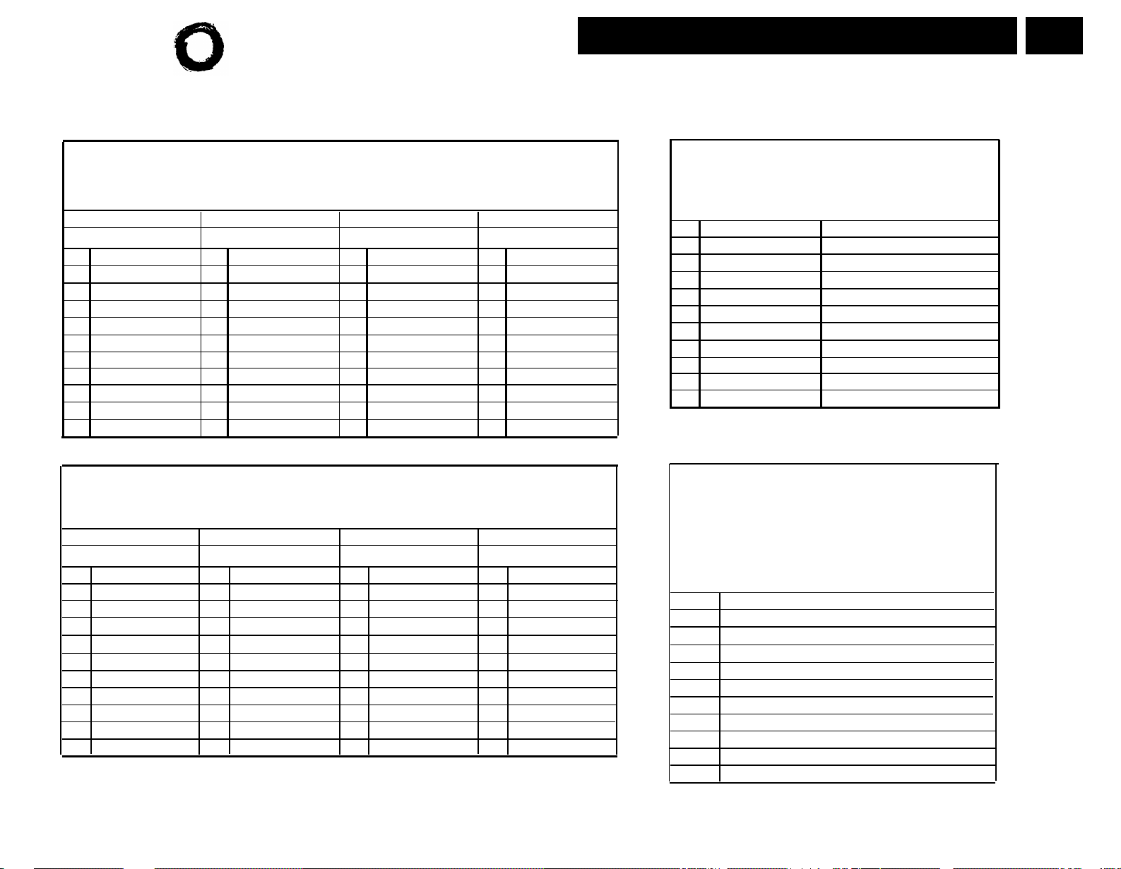
Lucent Technologies
Bell Labs Innovations
Form D: Number Lists
PAGE
1 of 2
Required if Form B1 identifies External Hotlines, or if Form B2
identifies Disallowed or Allowed List Assignments. For additional instructions,
see pages 14 and 15.
Disallowed Phone Number Lists {#404}
Required only if Disallowed List Assignment {#405} is specified on Form B2.
Write the telephone numbers that users are prevented from dialing.
List 4
Telephone Number’
Telephone Number
Entry
01
02
03
04
05
06
07
08
09
10
List 1
List 2 List 3
1
Telephone Number
Entry
01 01
02 02
03 03
04 04
05
06
07 07
08
09
10
1
Entry
Telephone Number
05 05
06
08
09
10 10
1
Entry
01
02
03
04
06
07
08
09
Allowed Phone Number Lists {#407}
Required only if Allowed List Assignment {#408} is specified on Form B2.
Write the telephone numbers that users can dial regardless of assigned restrictions.
List 1
1
Telephone Number
Entry
01
02
03
04
05
06
07
08
09
10
1. Telephone Number can be up to 12 characters, including 0-9, *, and #. Write ! for wildcard (press Hold to program).
2. Telephone Number can be up to 12 digits (0-9).
3. Telephone Number can be up to 28 characters, including 0-9, *,
than 10 External Hotlines.
Entry
01
02
03
04
05 05
06
07 07
08
09
10 10 10
List 2
Telephone Number
1
Entry
01
02
03
04
06
08
09
List 3
Telephone Number
1
Entry
01
02
03
04
05
06
07
08
09
#, and special dialing functions. You can have more
List 4
Telephone Number
1
Emergency Phone Number List {#406}
Write Emergency Phone Numbers that can be
dialed from any phone that has access to an
outside line regardless of assigned restrictions.
Entry
Telephone Number
2
Person/Place
01
02
03
04
05
06
07
08
09
10
External Hotline {#311}
Required if External Hotline {#311}
is checked on Form B1.
Write Extension Jack number specified on
Form B1, and the corresponding telephone
number to be assigned to Personal Speed Dial
Code 80 for that extension.
Ext.Jack
NOTE:
An External Hotline phone is a phone that dials the specified
telephone number when the handset is lifted.
Telephone Number
3
Page 37
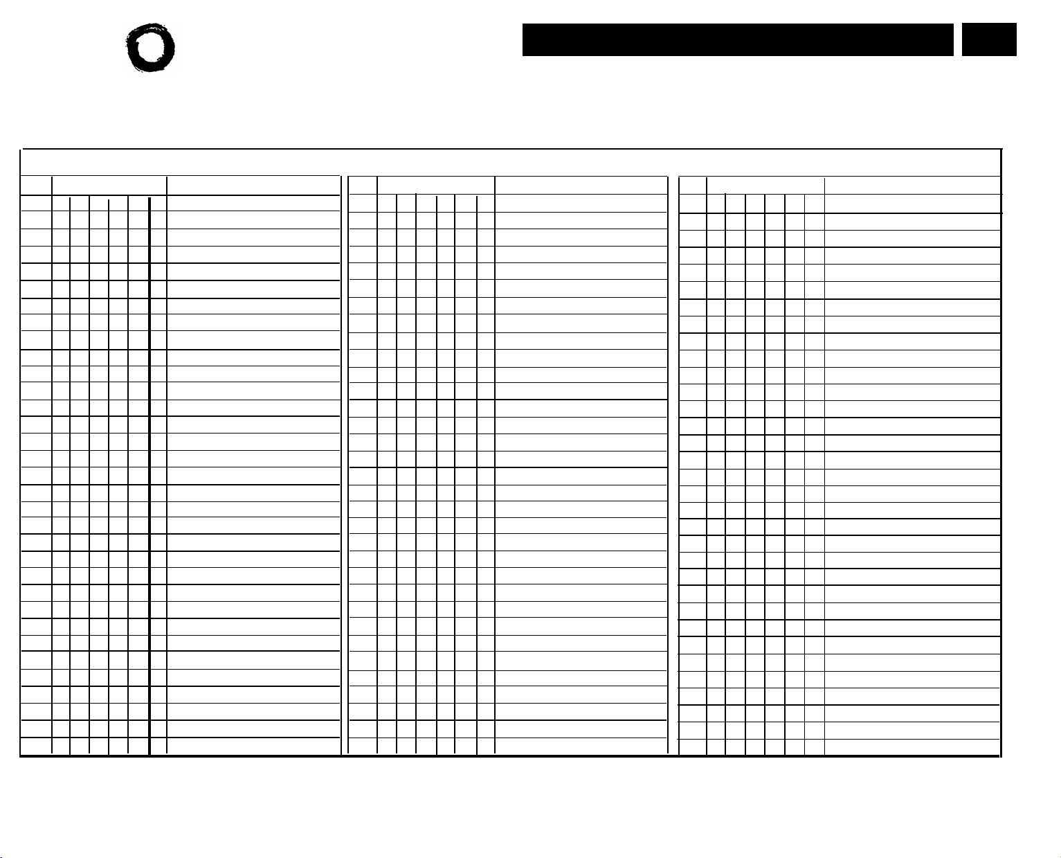
Lucent Technologies
Bell Labs Innovations
Entry Account Code (up to 6 digits)
1
Write Description
01
02 35
03 36
04
05 38
06 39
07 40
08 41
09 42
10
11
12 45
13 46
14
15 48
16 49
17 50
18 51
19
20 53
21 54
22 55
23
24 57
25 58
26 59
27 60
28 61
29 62
30 63
31
32
33 66
1. Valid entries are 0-9; write ! for wildcard (press Hold to program).
Form D: Number Lists
Required only if Forced Account Code Verification is desired.
For additional instructions, see page 15.
Forced Account Code List {#409}
Entry
Account Code (up to 6 digits)
34
37
43
44
47
52
56
64
65
1
Write Description
Acccount Code (up to 6 digits)
Entry
67
68
69
70
71
72
73
74
75
76
77
78
79
80
81
82
83
84
85
86
87
88
89
90
91
92
93
94
95
96
97
98
99
PAGE
2 of 2
1
Write Description
Page 38
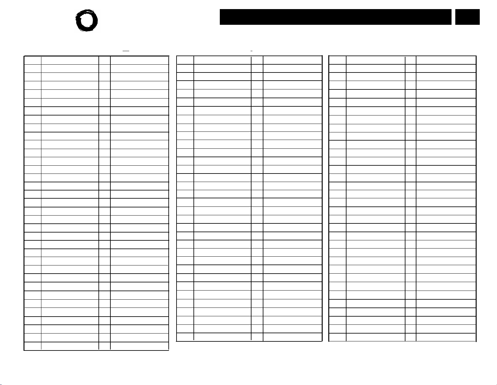
Lucent Technologies
Bell Labs Innovations
Form E: System Speed Dial Numbers
Optional for PARTNER II System and PARTNER Plus System.
For additional instructions, see page 16.
PAGE
1 of 1
To Dial:
On system phones, press
Code Name/Company
600
601
602
603
604
605
606
607
608
609
610
611
612
613
614
615
616
617
618
619
620
621
622
623
624
625
626
627
628
629
630
631
632
633
Feat
1
Telephone Number
★
+ 3-digit code. On standard phones, press
2
Code
Name/Company
634
635
636
637
638
639
640
641
642
643
644
645
646
647
648
649
650
651
652
653
654
655
656
657
658
659
660
661
662
663
664
665
666
You can dial System Speed Dial numbers that are marked
1
★ at any time, regardless of dialing restrictions placed on
with
your extension. System Speed Dial numbers are programmed
by the System Manager (report problems and suggested
revisions to your System Manager).
#
+ 3-digit code while receiving intercom dial tone.
1
Telephone Number
★
2
Code Name/Company
667
668
669
670
671
672
673
674
675
676
677
678
679
680
681
682
683
684
685
686
687
688
689
690
691
692
693
694
695
696
697
698
699
2 Telephone number can be up to 28 digits, including 0-9, *, #
and special dialing functions (see page 16 of instructions for
detailed information).
1
Telephone Number
★
2
Page 39

Lucent Technologies 518-455-338
Issue 2
August 1996
 Loading...