

Page 1

Doc. No.: 255-700-379
PacketStar® PSAX
12-Port Medium-Density
DS1/E1/DS0A CES Module User Guide
(DS1 Mode)
for PacketStar® PSAX Multiservice Media Gateways
Issue 1, September 2002
System Software Release 8.0.0
AQueView
®
EMS Software Release 6.0.0
Page 2

Copyright © 2002 by Lucent Technologies, Inc. All rights reserved.
For trademark, regulatory compliance, and related legal information, see the
"Legal Notices, Safety, and Regulatory Information" section of this document.
Page 3

255-700-379 iii
PacketStar
®
PSAX 12-Port Medium-Density DS1/E1/DS0A CES Module User Guide (DS1 Mode), Issue 1 Release 8.0.0
Legal Notices, Safety, and Regulatory
Information
Copyright
Copyright © 2002 by Lucent Technologies. All rights reserved.
This material is protected by the copyright laws of the United States and
other countries. It may not be reproduced, distributed, or altered in any fashion by any entity (either internal or external to Lucent Technologies), except
in accordance with applicable agreements, contracts or licensing, without the
express written consent of the originating organization and the business
management owner of the material.
This document was prepared by the Information Design and Development
Team of Lucent Technologies, PacketStar PSAX products. Offices are located
in Landover, Maryland, USA.
Trademarks
PacketStar , AQueView, Lucent, Lucent Technologies, and the Lucent Technolo-
gies logo are registered trademarks of Lucent Technologies in the USA. Other
product and brand names mentioned in this guide are trademarks or registered trademarks of their respective owners.
Notice
The information in this document is for informational use only, is subject to
change without notice, and should not be construed as a commitment by
Lucent Technologies, Inc. This document is without warranty of any kind,
either expressed or implied. Lucent Technologies, Inc. assumes no responsibility for any errors, inaccuracies, or omissions. Neither is any liability
assumed for damages resulting from the use of the information or instructions contained herein. Lucent Technologies, Inc. is not responsible for any
damage or loss to your data or equipment resulting either directly or indirectly from use of this document.
Page 4
iv 255-700-379
PacketStar
®
PSAX 12-Port Medium-Density DS1/E1/DS0A CES Module User Guide (DS1 Mode), Issue 1 Release 8.0.0
Warranty Information
Software and Hardware Limited Warranties
Lucent Technologies provides a 90-day limited software warranty, and a oneyear limited hardware warranty on this product. Refer to the Software License
and Limited Warranty Agreement and the Lucent Technologies InterNetworking Systems Global Warranty that accompanied your package for more information.
Warr anty Warnings
!
CAUTION:
Modifying or tampering with PSAX chassis components may void your
warranty. Any modification to this equipment not expressly authorized
by Lucent Technologies may void your granted authority to operate such
equipment.
!
CAUTION:
When inserting modules into the chassis, slide them gently, not forcefully. Excessive force may cause the modules to be seated improperly in
the chassis, and result in possible damage to the module or the chassis.
Install or remove modules one at a time. Doing this aids in preventing
the PSAX system from indicating any erroneous failure messages, and
allows the PSAX system to reinitialize and display the accurate configuration of the module that is inserted.
!
CAUTION:
Shipping the chassis with removable I/O, server, or CPU modules
installed may cause damage to the chassis and the modules. Damage to
any of the components in the system resulting from shipping the chassis
with removable modules installed will void your warranty. Only Lucentauthorized personnel should ship the PSAX chassis with a module
installed.
Safety Warnings and Information
When installing and operating the 12-Port Medium-Density DS1/E1/DS0A
CES module, follow the safety guidelines provided in the printed PacketStar
®
PSAX Safety Guidelines, which accompanies this product, to help prevent serious personal injury and damage to the 12-Port Medium-Density
DS1/E1/DS0A CES module. Please read all warnings and instructions supplied before beginning installation or configuration of this module. In addition to the general safety information provided, you should also refer to the
Page 5

255-700-379 v
PacketStar
®
PSAX 12-Port Medium-Density DS1/E1/DS0A CES Module User Guide (DS1 Mode), Issue 1 Release 8.0.0
text in the PacketStar PSAX user and installation guides for other important
safety information and procedures.
Regulatory Standards Compliance
Safety and Electromagnetic Compatibility (EMC)
The following PacketStar PSAX systems are compliant with applicable safety
and EMC standards when configured with the 12-Port Medium-Density
DS1/E1/DS0A CESmodule (model 24N64):
• PSAX 1000 system
• PSAX 1250 system
• PSAX 2300 system
• PSAX 4500 system
Please refer to the appropriate PacketStar PSAX Multiservice Media Gateway
user guide or installation guide for additional information.
Telecommunications
• FCC Part 68 (USA)
• CS-03 Issue 8 (Canada)
Regulatory Statements
USA Regulatory State ments
FCC Part 68 This equipment complies with Part 68 of the FCC rules. On the back of the
PSAX chassis is a label that contains the FCC registration number, in addition
to other information. You must provide this information to the telephone
company, if they request it. The FCC requires Lucent Technologies to provide
you with the following information:
1. This equipment has digital service interface capabilities using RJ-48C
and RJ-48H connectors. The facility interface codes with which this
equipment complies for digital services are as follows: 04DU9-BN,
04DU9-DN, 04DU9-1KN, and 04DU9-1SN. This equipment has loop
start interface capabilities using an RJ-11C connector. The facility interface code with which this equipment complies for service is 02LS2. The
service order codes for this equipment are 6.0F for the T1 interface and
9.0Y for the loop start interface.
2. An FCC-compliant telephone network interface jack is built into this
equipment and is compatible with interconnections that are Part 68
compliant.
Page 6

vi 255-700-379
PacketStar
®
PSAX 12-Port Medium-Density DS1/E1/DS0A CES Module User Guide (DS1 Mode), Issue 1 Release 8.0.0
3. The REN for the Voice 2-Wire Office module when used in this equipment is 0.7B.
4. If this equipment causes harm to the telephone network, the telephone
company will notify you in advance that temporary discontinuance of
service might be required. But if advance notice is not practical, the telephone company will notify you as soon as possible. Also, you will be
advised of your right to file a complaint with the FCC if you believe this
is necessary.
5. The telephone company might make changes in its facilities, equipment,
operations, or procedures that could affect the operation of this equipment. If this happens, the telephone company will provide advance
notice for you to make necessary modifications to maintain uninterrupted service.
6. If you experience trouble with this equipment, or need repairs or warranty information, please refer to the Lucent Technologies InterNetworking
Systems Global Warranty that accompanied your PSAX product shipment
for instructions on obtaining technical support in your area.
If this equipment is causing harm to the telephone network, the telephone company might request that you disconnect the equipment until
the problem is resolved.
7. This equipment has no user-serviceable parts.
This equipment cannot be used on public coin telephone service provided by
the telephone company. Connection to party line service is subject to state
tariffs. Contact your state public utility commission, public service commission, or corporation commission for information.
Canadian Regulatory Statements
CS-03 Issue 8 NOTICE: This equipment meets applicable Industry Canada Termi-
nal Equipment Technical Specifications. This is confirmed by the registration number. The abbreviation, IC, before the registration number signifies that registration was performed based on a Declaration
of Conformity indicating that Industry Canada technical specifications were met. It does not imply that Industry Canada approved the
equipment.
The Ringer Equivalence Number (REN) assigned to the Voice 2-Wire Office
module denotes the percentage of the total load to be connected to a telephone loop, which is used by the device, to prevent overloading. The termination on a loop may consist of any combination of devices subject only to
the requirement that the total of the REN of all devices does not exceed 5.
The REN for the Voice 2-Wire Office module when used in the PSAX system
is 0.7B.
SH-03 Version 8 AVIS: Le présent matériel est conforme aux spécifications techniques
d’Industrie Canada applicables au matériel terminal. Cette conformité est confirmée par le numéro d’enregistrement. Le sigle, IC,
Page 7

255-700-379 vii
PacketStar
®
PSAX 12-Port Medium-Density DS1/E1/DS0A CES Module User Guide (DS1 Mode), Issue 1 Release 8.0.0
placé devant le numéro d’enregistrement, signifie que l’enregistrement s’est effectué conformément à une déclaration de conformité
et indique que les spécifications techniques d’Industrie Canada ont
été respectées. Il n’implique pas qu’Industrie Canada a approuvé le
matériel.
Le nombre équivalent de sonnerie (REN) attribué au module central bifilaire
(Voice 2-Wire Office) correspond au pourcentage de la charge totale à connecter à un circuit téléphonique bifilaire; il est utilisé par l’appareil pour
prévenir la surcharge. Le circuit peut être terminé par n’importe quelle combinaison d’appareils, à la seule condition que le total des REN de ces derniers
ne dépasse pas cinq.
Lorsqu’il est utilisé dans le système PSAX, le module central bifilaire possède
un REN de 0,7 B.
Page 8

viii 255-700-379
PacketStar
®
PSAX 12-Port Medium-Density DS1/E1/DS0A CES Module User Guide (DS1 Mode), Issue 1 Release 8.0.0
Page 9

255-700-379 vii
PacketStar
®
PSAX 12-Port Medium-Density DS1/E1/DS0A CES Module User Guide (DS1 Mode), Issue 1 Release 8.0.0
Contents
Legal Notices, Safety, and Regulatory Information . . . . . . . . . . . . . . . . . . . . . . iii
Copyright . . . . . . . . . . . . . . . . . . . . . . . . . . . . . . . . . . . . . . . . . . . . . . . . . . . . . . . . . . . . .iii
Trademarks . . . . . . . . . . . . . . . . . . . . . . . . . . . . . . . . . . . . . . . . . . . . . . . . . . . . . . . . . . . . iii
Notice . . . . . . . . . . . . . . . . . . . . . . . . . . . . . . . . . . . . . . . . . . . . . . . . . . . . . . . . . . . . . . . . iii
Warranty Information . . . . . . . . . . . . . . . . . . . . . . . . . . . . . . . . . . . . . . . . . . . . . . . . . . . .iv
Software and Hardware Limited Warranties . . . . . . . . . . . . . . . . . . . . . . . . . . . . . . . .iv
Warranty Warnings . . . . . . . . . . . . . . . . . . . . . . . . . . . . . . . . . . . . . . . . . . . . . . . . . . .iv
Safety Warnings and Information . . . . . . . . . . . . . . . . . . . . . . . . . . . . . . . . . . . . . . . . . . . iv
Regulatory Standards Compliance . . . . . . . . . . . . . . . . . . . . . . . . . . . . . . . . . . . . . . . . . . . v
Safety and Electromagnetic Compatibility (EMC) . . . . . . . . . . . . . . . . . . . . . . . . . . . . . v
Telecommunications . . . . . . . . . . . . . . . . . . . . . . . . . . . . . . . . . . . . . . . . . . . . . . . . . . v
Regulatory Statements . . . . . . . . . . . . . . . . . . . . . . . . . . . . . . . . . . . . . . . . . . . . . . . . . . . v
USA Regulatory Statements . . . . . . . . . . . . . . . . . . . . . . . . . . . . . . . . . . . . . . . . . . . . v
FCC Part 68 . . . . . . . . . . . . . . . . . . . . . . . . . . . . . . . . . . . . . . . . . . . . . . . . . . . . . v
Canadian Regulatory Statements . . . . . . . . . . . . . . . . . . . . . . . . . . . . . . . . . . . . . . . .vi
CS-03 Issue 8 . . . . . . . . . . . . . . . . . . . . . . . . . . . . . . . . . . . . . . . . . . . . . . . . . . . . vi
SH-03 Version 8 . . . . . . . . . . . . . . . . . . . . . . . . . . . . . . . . . . . . . . . . . . . . . . . . . .vi
Figures . . . . . . . . . . . . . . . . . . . . . . . . . . . . . . . . . . . . . . . . . . . . . . . . . . . . . . . . . . xi
Tables . . . . . . . . . . . . . . . . . . . . . . . . . . . . . . . . . . . . . . . . . . . . . . . . . . . . . . . . . . xiii
1 Getting Started. . . . . . . . . . . . . . . . . . . . . . . . . . . . . . . . . . . . . . . . . . . . . . . . . 1-1
Purpose of This Guide . . . . . . . . . . . . . . . . . . . . . . . . . . . . . . . . . . . . . . . . . . . . . . . . . . .1-1
Audience for This Guide. . . . . . . . . . . . . . . . . . . . . . . . . . . . . . . . . . . . . . . . . . . . . . . . . .1-1
What You Should Know. . . . . . . . . . . . . . . . . . . . . . . . . . . . . . . . . . . . . . . . . . . . . . . . . .1-1
Related Reading . . . . . . . . . . . . . . . . . . . . . . . . . . . . . . . . . . . . . . . . . . . . . . . . . . . . . . . .1-2
Lucent Technologies Information Products . . . . . . . . . . . . . . . . . . . . . . . . . . . . . . . . .1-2
Product Information Library . . . . . . . . . . . . . . . . . . . . . . . . . . . . . . . . . . . . . . . . .1-2
Printed Documents. . . . . . . . . . . . . . . . . . . . . . . . . . . . . . . . . . . . . . . . . . . . . . . .1-2
Other Publications . . . . . . . . . . . . . . . . . . . . . . . . . . . . . . . . . . . . . . . . . . . . . . . . . . .1-2
About Lucent Technologies. . . . . . . . . . . . . . . . . . . . . . . . . . . . . . . . . . . . . . . . . . . . . . . .1-2
For More Information. . . . . . . . . . . . . . . . . . . . . . . . . . . . . . . . . . . . . . . . . . . . . . . . . . . .1-2
About the PacketStar® PSAX Product Family . . . . . . . . . . . . . . . . . . . . . . . . . . . . . . . . . .1-3
PSAX 1000 Multiservice Media Gateway . . . . . . . . . . . . . . . . . . . . . . . . . . . . . . . . . .1-3
PSAX 1250 Multiservice Media Gateway . . . . . . . . . . . . . . . . . . . . . . . . . . . . . . . . . .1-3
Page 10

Contents
255-700-379 viii
PacketStar
®
PSAX 12-Port Medium-Density DS1/E1/DS0A CES Module User Guide (DS1 Mode), Issue 1 Release 8.0.0
PSAX 2300 Multiservice Media Gateway. . . . . . . . . . . . . . . . . . . . . . . . . . . . . . . . . . 1-3
PSAX 4500 Multiservice Media Gateway. . . . . . . . . . . . . . . . . . . . . . . . . . . . . . . . . . 1-4
Conventions . . . . . . . . . . . . . . . . . . . . . . . . . . . . . . . . . . . . . . . . . . . . . . . . . . . . . . . . . . 1-4
Text Types Used in This Document. . . . . . . . . . . . . . . . . . . . . . . . . . . . . . . . . . . . . . . 1-4
Icons and Symbols . . . . . . . . . . . . . . . . . . . . . . . . . . . . . . . . . . . . . . . . . . . . . . . . . . 1-5
Use of Command Description Tables . . . . . . . . . . . . . . . . . . . . . . . . . . . . . . . . . . . . . 1-6
Use of Field Description Tables. . . . . . . . . . . . . . . . . . . . . . . . . . . . . . . . . . . . . . . . . . 1-6
Selecting Options, Fields, and Commands. . . . . . . . . . . . . . . . . . . . . . . . . . . . . . . . . 1-7
Help Information . . . . . . . . . . . . . . . . . . . . . . . . . . . . . . . . . . . . . . . . . . . . . . . . . . . . . . . 1-9
Technical Support . . . . . . . . . . . . . . . . . . . . . . . . . . . . . . . . . . . . . . . . . . . . . . . . . . . . . 1-10
Comments on This Guide . . . . . . . . . . . . . . . . . . . . . . . . . . . . . . . . . . . . . . . . . . . . . . . 1-10
Before You Begin. . . . . . . . . . . . . . . . . . . . . . . . . . . . . . . . . . . . . . . . . . . . . . . . . . . . . . 1-10
2 Module Description . . . . . . . . . . . . . . . . . . . . . . . . . . . . . . . . . . . . . . . . . . . . . 2-1
Overview of This Module. . . . . . . . . . . . . . . . . . . . . . . . . . . . . . . . . . . . . . . . . . . . . . . . . 2-1
Connection Options . . . . . . . . . . . . . . . . . . . . . . . . . . . . . . . . . . . . . . . . . . . . . . . . . . . . 2-2
Software Features . . . . . . . . . . . . . . . . . . . . . . . . . . . . . . . . . . . . . . . . . . . . . . . . . . . . . . 2-5
Hardware Features . . . . . . . . . . . . . . . . . . . . . . . . . . . . . . . . . . . . . . . . . . . . . . . . . . 2-5
Hardware Specifications . . . . . . . . . . . . . . . . . . . . . . . . . . . . . . . . . . . . . . . . . . . . . . 2-5
Performance and Power Specifications . . . . . . . . . . . . . . . . . . . . . . . . . . . . . . . . . . . 2-6
Module Placement . . . . . . . . . . . . . . . . . . . . . . . . . . . . . . . . . . . . . . . . . . . . . . . . . . 2-6
LED Indicators. . . . . . . . . . . . . . . . . . . . . . . . . . . . . . . . . . . . . . . . . . . . . . . . . . . . . . 2-7
3 Configuring Ports and Channels Using the Console . . . . . . . . . . . . . . . . . . . 3-1
Overview of This Chapter . . . . . . . . . . . . . . . . . . . . . . . . . . . . . . . . . . . . . . . . . . . . . . . . 3-1
Loopback Configuration Options. . . . . . . . . . . . . . . . . . . . . . . . . . . . . . . . . . . . . . . . . . . 3-1
Configuring the Module . . . . . . . . . . . . . . . . . . . . . . . . . . . . . . . . . . . . . . . . . . . . . . . . . 3-2
Configuring Ports and Channels in the DS1 Mode. . . . . . . . . . . . . . . . . . . . . . . . . . . 3-2
Port with One Channel . . . . . . . . . . . . . . . . . . . . . . . . . . . . . . . . . . . . . . . . . . . 3-12
Port with Several Channels . . . . . . . . . . . . . . . . . . . . . . . . . . . . . . . . . . . . . . . . 3-15
Port Statistics . . . . . . . . . . . . . . . . . . . . . . . . . . . . . . . . . . . . . . . . . . . . . . . . . . . . . 3-18
Saving the Equipment Configuration and Logging Off. . . . . . . . . . . . . . . . . . . . . . . . . . 3-21
4 Configuring the Interfaces Using the Console. . . . . . . . . . . . . . . . . . . . . . . . 4-1
Overview of This Chapter . . . . . . . . . . . . . . . . . . . . . . . . . . . . . . . . . . . . . . . . . . . . . . . . 4-1
Before You Begin. . . . . . . . . . . . . . . . . . . . . . . . . . . . . . . . . . . . . . . . . . . . . . . . . . . . . . . 4-1
Errors in Applying Interfaces to Ports . . . . . . . . . . . . . . . . . . . . . . . . . . . . . . . . . . . . . . . . 4-1
Configuring the Circuit Emulation Interface. . . . . . . . . . . . . . . . . . . . . . . . . . . . . . . . . . . 4-2
Configuring the PRI ISDN Network/User Interface . . . . . . . . . . . . . . . . . . . . . . . . . . . . . . 4-6
Provisioning Connections. . . . . . . . . . . . . . . . . . . . . . . . . . . . . . . . . . . . . . . . . . . . . . . . . 4-9
Page 11

Contents
255-700-379 ix
PacketStar
®
PSAX 12-Port Medium-Density DS1/E1/DS0A CES Module User Guide (DS1 Mode), Issue 1 Release 8.0.0
5 Configuring Ports and Channels Using the AQueView® System . . . . . . . . . 5-1
Overview of This Chapter . . . . . . . . . . . . . . . . . . . . . . . . . . . . . . . . . . . . . . . . . . . . . . . . .5-1
Before You Begin . . . . . . . . . . . . . . . . . . . . . . . . . . . . . . . . . . . . . . . . . . . . . . . . . . . . . . .5-1
Loopback Configuration Options . . . . . . . . . . . . . . . . . . . . . . . . . . . . . . . . . . . . . . . . . . .5-1
Obtaining Port and Interface Data . . . . . . . . . . . . . . . . . . . . . . . . . . . . . . . . . . . . . . . . . .5-1
Using the Right-Click Menu . . . . . . . . . . . . . . . . . . . . . . . . . . . . . . . . . . . . . . . . . . . . . . .5-5
Configuring Ports and Channels. . . . . . . . . . . . . . . . . . . . . . . . . . . . . . . . . . . . . . . . . . . .5-5
Configuring the Module. . . . . . . . . . . . . . . . . . . . . . . . . . . . . . . . . . . . . . . . . . . . . . . . . .5-7
Changing the Operating Mode . . . . . . . . . . . . . . . . . . . . . . . . . . . . . . . . . . . . . . . . .5-7
Configuring the Ports . . . . . . . . . . . . . . . . . . . . . . . . . . . . . . . . . . . . . . . . . . . . . . . .5-9
Viewing Port Statistics . . . . . . . . . . . . . . . . . . . . . . . . . . . . . . . . . . . . . . . . . . . . . . .5-16
Configuring the Channels . . . . . . . . . . . . . . . . . . . . . . . . . . . . . . . . . . . . . . . . . . . .5-18
Applying an Interface to a Channel . . . . . . . . . . . . . . . . . . . . . . . . . . . . . . . . . .5-18
Strapping DS0s . . . . . . . . . . . . . . . . . . . . . . . . . . . . . . . . . . . . . . . . . . . . . . . . .5-20
Configuring an Interface . . . . . . . . . . . . . . . . . . . . . . . . . . . . . . . . . . . . . . . . . .5-21
Copying a Port Configuration. . . . . . . . . . . . . . . . . . . . . . . . . . . . . . . . . . . . . . . . . . . . .5-21
Obtaining Status Data for Modules. . . . . . . . . . . . . . . . . . . . . . . . . . . . . . . . . . . . . . . . .5-23
Obtaining Hardware Operating Status Data . . . . . . . . . . . . . . . . . . . . . . . . . . . . . . .5-23
Obtaining LED Status Indicator Data. . . . . . . . . . . . . . . . . . . . . . . . . . . . . . . . . . . . .5-23
Obtaining Port Configuration Data. . . . . . . . . . . . . . . . . . . . . . . . . . . . . . . . . . . . . .5-24
Ghosted Modules . . . . . . . . . . . . . . . . . . . . . . . . . . . . . . . . . . . . . . . . . . . . . . . . . .5-26
Saving the Configuration . . . . . . . . . . . . . . . . . . . . . . . . . . . . . . . . . . . . . . . . . . . . . . . .5-27
6 Configuring the Interfaces Using the AQueView® System. . . . . . . . . . . . . . 6-1
Overview of This Chapter . . . . . . . . . . . . . . . . . . . . . . . . . . . . . . . . . . . . . . . . . . . . . . . . .6-1
Before You Begin . . . . . . . . . . . . . . . . . . . . . . . . . . . . . . . . . . . . . . . . . . . . . . . . . . . . . . .6-1
Errors in Applying Interfaces to Ports . . . . . . . . . . . . . . . . . . . . . . . . . . . . . . . . . . . . . . . .6-1
Configuring the Circuit Emulation Interface . . . . . . . . . . . . . . . . . . . . . . . . . . . . . . . . . . .6-2
Configuring Circuit Emulation Interface Values. . . . . . . . . . . . . . . . . . . . . . . . . . . . . .6-4
Configuring the PRI ISDN Network/User Interface. . . . . . . . . . . . . . . . . . . . . . . . . . . . . . .6-8
Performing Bulk Operations . . . . . . . . . . . . . . . . . . . . . . . . . . . . . . . . . . . . . . . . . . . . . .6-11
Copying an Interface Configuration . . . . . . . . . . . . . . . . . . . . . . . . . . . . . . . . . . . . . . . .6-14
Saving Your Configuration . . . . . . . . . . . . . . . . . . . . . . . . . . . . . . . . . . . . . . . . . . . . . . .6-16
Provisioning Connections . . . . . . . . . . . . . . . . . . . . . . . . . . . . . . . . . . . . . . . . . . . . . . . .6-16
Appendix A: Pin Configurations. . . . . . . . . . . . . . . . . . . . . . . . . . . . . . . . . . . . . A-1
Overview of This Appendix. . . . . . . . . . . . . . . . . . . . . . . . . . . . . . . . . . . . . . . . . . . . . . . A-1
Configurations for the 12-Port MD DS1/E1/DS0A CES Module Connectors. . . . . . . . . . . A-1
Page 12

Contents
255-700-379 x
PacketStar
®
PSAX 12-Port Medium-Density DS1/E1/DS0A CES Module User Guide (DS1 Mode), Issue 1 Release 8.0.0
Appendix B: Reference Information. . . . . . . . . . . . . . . . . . . . . . . . . . . . . . . . . . B-1
Overview of This Appendix . . . . . . . . . . . . . . . . . . . . . . . . . . . . . . . . . . . . . . . . . . . . . . . B-1
ATM Traffic Descriptors . . . . . . . . . . . . . . . . . . . . . . . . . . . . . . . . . . . . . . . . . . . . . . . . . . B-1
Purpose of Traffic Descriptors . . . . . . . . . . . . . . . . . . . . . . . . . . . . . . . . . . . . . . . . . . B-1
Connections Supporting Traffic Descriptors . . . . . . . . . . . . . . . . . . . . . . . . . . . . . . . . B-1
ATM User-Network Interface Specification Cause Codes Table . . . . . . . . . . . . . . . . . . . . . B-3
DSP Tone Detection Modes Table. . . . . . . . . . . . . . . . . . . . . . . . . . . . . . . . . . . . . . . . . . . B-7
DSP2C Module Channel Reduction When Using Fax Relay Mode Table . . . . . . . . . . . . . . B-8
Industry Compliance Specifications Table. . . . . . . . . . . . . . . . . . . . . . . . . . . . . . . . . . . . . B-8
Interface Type by Connection Type Table . . . . . . . . . . . . . . . . . . . . . . . . . . . . . . . . . . . . B-18
Interface Type by I/O Module T ype Table. . . . . . . . . . . . . . . . . . . . . . . . . . . . . . . . . . . . . B-19
Module Alarm Status Table . . . . . . . . . . . . . . . . . . . . . . . . . . . . . . . . . . . . . . . . . . . . . . B-23
Quality of Service (QoS) Information Tables . . . . . . . . . . . . . . . . . . . . . . . . . . . . . . . . . . B-24
Glossary. . . . . . . . . . . . . . . . . . . . . . . . . . . . . . . . . . . . . . . . . . . . . . . . . . . Glossary-1
Page 13

255-700-379 xi
PacketStar
®
PSAX 12-Port Medium-Density DS1/E1/DS0A CES Module User Guide (DS1 Mode), Issue 1 Release 8.0.0
Figures
1-1 Main Menu Help Window . . . . . . . . . . . . . . . . . . . . . . . . . . . . . . . . . . . . . . . . . . . . . . . . . 1-9
2-1 12-Port Medium-Density DS1/E1/DS0A CES Module . . . . . . . . . . . . . . . . . . . . . . . . . . . . . . 2-1
2-2 12-Port MD DS1/E1/DS0A CES Module Cable Connection (with Cinch connector) . . . . . . . 2-2
2-3 12-Port Medium-Density DS1/E1/DS0A CES Modules Connected to 24-port RJ Patch Panel
(Telco frame with modules) . . . . . . . . . . . . . . . . . . . . . . . . . . . . . . . . . . . . . . . . . . . . . . 2-3
2-4 12-Port Medium-Density DS1/E1/DS0A CES Modules Connected to 24-port RJ Patch Panel
(Telco frame with patch panel) . . . . . . . . . . . . . . . . . . . . . . . . . . . . . . . . . . . . . . . . . . . . 2-3
2-5 12-Port Medium-Density DS1/E1/DS0A CES Modules Connected to 48-port RJ Patch Panel
(Telco frame with modules) . . . . . . . . . . . . . . . . . . . . . . . . . . . . . . . . . . . . . . . . . . . . . . 2-4
2-6 12-Port Medium-Density DS1/E1/DS0A CES Modules Connected to 48-port RJ Patch Panel
(Telco frame with patch panel) . . . . . . . . . . . . . . . . . . . . . . . . . . . . . . . . . . . . . . . . . . . . 2-4
3-1 Loopback Configuration Options . . . . . . . . . . . . . . . . . . . . . . . . . . . . . . . . . . . . . . . . . . . . 3-1
3-2 Console Interface Main Menu Window (Equipment Configuration Selected) . . . . . . . . . . . . 3-2
3-3 Equipment Configuration Window (As Displayed on the PSAX 1250, PSAX 2300, and PSAX
4500 Console, Page 1) . . . . . . . . . . . . . . . . . . . . . . . . . . . . . . . . . . . . . . . . . . . . . . . . . . 3-3
3-4 Equipment Configuration Window (As Displayed on the PSAX 1250, PSAX 2300, and PSAX
4500 Console, Page 2 ) . . . . . . . . . . . . . . . . . . . . . . . . . . . . . . . . . . . . . . . . . . . . . . . . . 3-3
3-5 12-Port Medium-Density DS1 Port Configuration Window . . . . . . . . . . . . . . . . . . . . . . . . . 3-4
3-6 12-Port Medium-Density DS1 Port and Channel Configuration Window (Channelization
Disabled) . . . . . . . . . . . . . . . . . . . . . . . . . . . . . . . . . . . . . . . . . . . . . . . . . . . . . . . . . . . . . 3-6
3-7 Medium Density 12-Port DS1 Channel Configuration Window (One Channel per Port) . . . 3-12
3-8 12-Port Medium-Density DS1 Port and Channel Configuration Window (Channelization
Enabled) . . . . . . . . . . . . . . . . . . . . . . . . . . . . . . . . . . . . . . . . . . . . . . . . . . . . . . . . . . . .3-15
3-9 Medium Density 12-Port DS1 Channel Configuration Window (Several Channels per Port) 3-16
3-10 12-Port Medium-Density DS1 DS0s Strap Display Window . . . . . . . . . . . . . . . . . . . . . . . . 3-17
3-11 12-Port Medium-Density DS1 Port Statistics Window . . . . . . . . . . . . . . . . . . . . . . . . . . . . 3-19
4-1 Circuit Emulation Interface Configuration Window . . . . . . . . . . . . . . . . . . . . . . . . . . . . . . . 4-3
4-2 Enhanced ISDN LAPD and BChannel Configuration Window . . . . . . . . . . . . . . . . . . . . . . . . 4-6
5-1 Sample Device Tree . . . . . . . . . . . . . . . . . . . . . . . . . . . . . . . . . . . . . . . . . . . . . . . . . . . . . . 5-2
5-2 Obtaining Hardware Data from a Module . . . . . . . . . . . . . . . . . . . . . . . . . . . . . . . . . . . . . . 5-3
5-3 Sample Module Information Window . . . . . . . . . . . . . . . . . . . . . . . . . . . . . . . . . . . . . . . . . 5-3
5-4 Sample Port Configuration (Displaying Right-Click Menu) . . . . . . . . . . . . . . . . . . . . . . . . . . 5-6
5-5 Sample of Context-Sensitive Help (Displayed on a Port and Channel Configuration Window) . .
5-7
5-6 Module Right-Click Menu . . . . . . . . . . . . . . . . . . . . . . . . . . . . . . . . . . . . . . . . . . . . . . . . . . 5-8
Page 14

xii 255-700-379
PacketStar
®
PSAX 12-Port Medium-Density DS1/E1/DS0A CES Module User Guide (DS1 Mode), Issue 1 Release 8.0.0
5-7 Module Information Window . . . . . . . . . . . . . . . . . . . . . . . . . . . . . . . . . . . . . . . . . . . . . . . 5-8
5-8 Front Panel View of the 12-Port Medium-Density DS1/E1/DS0A CES Module . . . . . . . . . . 5-10
5-9 12-Port Medium-Density DS1/E1/DS0A CES Module Port Configuration Window . . . . . . . 5-10
5-10 12-Port Medium-Density DS1/E1/DS0A CES Module Port Configuration Window (Menu
Displayed) . . . . . . . . . . . . . . . . . . . . . . . . . . . . . . . . . . . . . . . . . . . . . . . . . . . . . . . . . . . 5-11
5-11 12-Port Medium-Density DS1/E1/DS0A CES Module Port and Channel Configuration
Window . . . . . . . . . . . . . . . . . . . . . . . . . . . . . . . . . . . . . . . . . . . . . . . . . . . . . . . . . . . . 5-11
5-12 12-Port Medium-Density DS1/E1/DS0A CES Module Channel Configuration Page . . . . . . 5-20
5-13 Sample Copy Port Configuration Window (After Initially Selecting the Copy Button
From a Port Configuration Page) . . . . . . . . . . . . . . . . . . . . . . . . . . . . . . . . . . . . . . . . . . 5-22
5-14 Sample Copy Port Configuration Window (After Selecting a Valid Attributes) . . . . . . . . . 5-22
5-15 Obtaining Indicator Light Status Data . . . . . . . . . . . . . . . . . . . . . . . . . . . . . . . . . . . . . . . . 5-23
5-16 Status Data . . . . . . . . . . . . . . . . . . . . . . . . . . . . . . . . . . . . . . . . . . . . . . . . . . . . . . . . . . . 5-25
5-17 Device Tree Status Indicators . . . . . . . . . . . . . . . . . . . . . . . . . . . . . . . . . . . . . . . . . . . . . . 5-25
5-18 Device Tree (Displaying a Yellow Status Indicator) . . . . . . . . . . . . . . . . . . . . . . . . . . . . . . 5-26
6-1 Circuit Emulation Interface Configuration Window . . . . . . . . . . . . . . . . . . . . . . . . . . . . . . 6-2
6-2 PRI ISDN Interface Configuration Window (User) . . . . . . . . . . . . . . . . . . . . . . . . . . . . . . . . 6-8
6-3 Sample Copy Interface Configuration Window (After Initially Selecting the Copy Button
From a Port Configuration Page) . . . . . . . . . . . . . . . . . . . . . . . . . . . . . . . . . . . . . . . . . . 6-15
6-4 Sample Copy Interface Configuration Window (After Selecting Valid Attributes) . . . . . . . 6-15
A-1 Pin Locations on the Telco Port Socket Connector . . . . . . . . . . . . . . . . . . . . . . . . . . . . . . . A-2
Page 15

255-700-379 xiii
PacketStar
®
PSAX 12-Port Medium-Density DS1/E1/DS0A CES Module User Guide (DS1 Mode), Issue 1 Release 8.0.0
Tables
1-1 Text Conventions . . . . . . . . . . . . . . . . . . . . . . . . . . . . . . . . . . . . . . . . . . . . . . . . . . . . . . . . . 1-5
1-2 Text Conventions . . . . . . . . . . . . . . . . . . . . . . . . . . . . . . . . . . . . . . . . . . . . . . . . . . . . . . . . . 1-5
1-3 Command Description Table Example. . . . . . . . . . . . . . . . . . . . . . . . . . . . . . . . . . . . . . . . . . 1-6
1-4 Field Description Table Example . . . . . . . . . . . . . . . . . . . . . . . . . . . . . . . . . . . . . . . . . . . . . . 1-7
1-5 System Responses to Selecting Options, Fields, or Commands. . . . . . . . . . . . . . . . . . . . . . . . 1-8
1-6 Shortcut Keys for Navigating Console Interface Windows . . . . . . . . . . . . . . . . . . . . . . . . . . . 1-8
2-1 Physical Hardware Specifications for the I/O and the Server Modules. . . . . . . . . . . . . . . . . . . 2-5
2-2 Performance and Power Specifications for the 12-Port Medium-Density DS1/E1 /DS0A CES
Module . . . . . . . . . . . . . . . . . . . . . . . . . . . . . . . . . . . . . . . . . . . . . . . . . . . . . . . . . . . . . . . 2-6
2-3 LED Indicators for the 12-Port Medium-Density DS1/E1/DS0A CES Module . . . . . . . . . . . . . . 2-7
3-1 Field Descriptions for the 12-Port Medium-Density DS1 Port Configuration Window. . . . . . . 3-5
3-2 Field Descriptions for the 12-Port Medium-Density DS1 Port and Channel Configuration
Window . . . . . . . . . . . . . . . . . . . . . . . . . . . . . . . . . . . . . . . . . . . . . . . . . . . . . . . . . . . . . . 3-7
3-3 DS1 Line Status Alarms. . . . . . . . . . . . . . . . . . . . . . . . . . . . . . . . . . . . . . . . . . . . . . . . . . . . 3-11
3-4 Configuring Channels. . . . . . . . . . . . . . . . . . . . . . . . . . . . . . . . . . . . . . . . . . . . . . . . . . . . . 3-11
3-5 Field Descriptions for the Medium Density 12-Port DS1 Channel Configuration Window. . . 3-13
3-6 Field Descriptions for the 12-Port Medium-Density DS1 DS0s Strap Display Window. . . . . . 3-18
3-7 Field Descriptions for the 12-Port Medium-Density DS1 Port Statistics Window . . . . . . . . . 3-20
4-1 Field Descriptions for the Circuit Emulation Interface Configuration Window . . . . . . . . . . . . 4-4
4-2 Field Descriptions for the Enhanced ISDN LAPD and B Channel Configuration Window. . . . . 4-8
5-1 Field Descriptions for the Module Information Window . . . . . . . . . . . . . . . . . . . . . . . . . . . . 5-4
5-2 Field Descriptions for the 12-Port Medium-Density DS1 Port and Channel Configuration
Window . . . . . . . . . . . . . . . . . . . . . . . . . . . . . . . . . . . . . . . . . . . . . . . . . . . . . . . . . . . . . 5-13
5-3 DS1 Line Status Alarms. . . . . . . . . . . . . . . . . . . . . . . . . . . . . . . . . . . . . . . . . . . . . . . . . . . . 5-16
5-4 Field Descriptions for the 12-Port Medium-Density DS1 Port Statistics Window . . . . . . . . . 5-17
5-5 Selecting Channels for Configuration . . . . . . . . . . . . . . . . . . . . . . . . . . . . . . . . . . . . . . . . . 5-19
5-6 . . . . . . . . . . . . . . . . . . . . . . . . . . . . . . . . . . . . . . . . . . . . . . . . . . . . . . . . . . . . . . . . . . . . . 5-22
5-7 LED Status Indicator Descriptions . . . . . . . . . . . . . . . . . . . . . . . . . . . . . . . . . . . . . . . . . . . . 5-24
5-8 Port Status Data . . . . . . . . . . . . . . . . . . . . . . . . . . . . . . . . . . . . . . . . . . . . . . . . . . . . . . . . . 5-26
5-9 Removing Ghosted Modules from the Front Panel . . . . . . . . . . . . . . . . . . . . . . . . . . . . . . . 5-27
6-1 Field Descriptions for the Circuit Emulation Interface Configuration Window . . . . . . . . . . . . 6-6
6-2 Field Descriptions for the PRI ISDN Network/User Configuration Window . . . . . . . . . . . . . . 6-10
6-3 Performing an Action on an Interface . . . . . . . . . . . . . . . . . . . . . . . . . . . . . . . . . . . . . . . . . 6-12
Page 16

xiv 255-700-379
PacketStar
®
PSAX 12-Port Medium-Density DS1/E1/DS0A CES Module User Guide (DS1 Mode), Issue 1 Release 8.0.0
6-4 Enabling or Disabling Traps Decision Table . . . . . . . . . . . . . . . . . . . . . . . . . . . . . . . . . . . . . . 6-13
A-1 Telco Connector Pinouts for the 12-Port MD DS1/E1/DS0A CES Module . . . . . . . . . . . . . . . . A-1
A-2 Standard 25-Pair Telco Connector to RJ-48H Cable Wiring. . . . . . . . . . . . . . . . . . . . . . . . . . . A-3
B-1 Connection Cause Codes for SPVCs. . . . . . . . . . . . . . . . . . . . . . . . . . . . . . . . . . . . . . . . . . . . B-3
B-2 DSP Tone Detection Modes and Associated Processing Performed . . . . . . . . . . . . . . . . . . . . . B-7
B-3 Channel Reduction Availability Caused by Fax Relay Connections vs. Voice
Processing Connections on a DSP2C Module . . . . . . . . . . . . . . . . . . . . . . . . . . . . . . . . . . . B-8
B-4 Industry Compliance Specifications . . . . . . . . . . . . . . . . . . . . . . . . . . . . . . . . . . . . . . . . . . . . B-9
B-5 Connection Type by Interface Type Table . . . . . . . . . . . . . . . . . . . . . . . . . . . . . . . . . . . . . . . B-18
B-6 Interface Types by I/O Module Types . . . . . . . . . . . . . . . . . . . . . . . . . . . . . . . . . . . . . . . . . . B-19
B-7 Alarm Status Descriptions for Modules on the Equipment Configuration Window . . . . . . . . B-24
B-8 PSAX System-Supported Quality of Service Classes. . . . . . . . . . . . . . . . . . . . . . . . . . . . . . . . B-25
B-9 Class of Service Descriptions . . . . . . . . . . . . . . . . . . . . . . . . . . . . . . . . . . . . . . . . . . . . . . . . B-25
B-10 Cell Loss and Cell Delay Characteristics of ATM Service Classes . . . . . . . . . . . . . . . . . . . . . . B-26
B-11 Mapping ATM Service Classes to PSAX System Priority Levels . . . . . . . . . . . . . . . . . . . . . . . . B-26
Page 17

Part 1: General
Page 18

Page 19

PacketStar
®
PSAX 12-Port Medium-Density DS1/E1/DS0A CES Module User Guide (DS1 Mode), Issue 1 Release 8.0.0
255-700-379 1-1
1 Getting Started
Purpose of This Guide
The PacketStar® 12-Port Medium-Density DS1/E1/DS0A CES Module User Guide
(DS1 Mode) provides a description of the 12-Port Medium-Density
DS1/E1/DS0A CES module. It also provides the following information:
• PacketStar I/O module configuration overview
• Using the PSAX system to configure ports and channels
• Using the PSAX system to configure interfaces
For information on provisioning connections, see the PacketStar
®
PSAX System
Provisioning Connections User Guide for PacketStar
®
PSAX Multiservice Media Gate-
ways.
Audience for This Guide
The information in this guide is intended for users who will configure ports
and channels for the 12-Port Medium-Density DS1/E1/DS0A CES module in
the DS1 mode, configure the interface types, and provision connections for
the PSAX Multiservice Media Gateway system using the console interface. To
configure ports and channels for the 12-Port Medium-Density DS1/E1/DS0A
CES module in the DS0A mode, see the PacketStar
®
PSAX 12-Port
Medium-Density DS1/E1/DS0A CES Module User Guide (DS0A Mode),
255-700-378.
What You Should Know
Before you use this document or operate a PacketStar PSAX device, you
should already understand and have experience with the following:
• ATM Forum, Frame Relay Forum, and other telecommunications specifica-
tions
• Ethernet network capabilities
• Internet Protocol capabilities
• Data network design
• Telephony network design
Page 20

Chapter 1 Getting Started
Related Reading
1-2 255-700-379
PacketStar
®
PSAX 12-Port Medium-Density DS1/E1/DS0A CES Module User Guide (DS1 Mode), Issue 1 Release 8.0.0
Related Reading
Lucent Technologies Information Products
Product Information
Library
To install, operate, and configure your PSAX system and I/O and server modules, read the PSAX publications provided on your Lucent Technologies Pack-
etStar PSAX Multiservice Media Gateways Products, Product Information
Library CD-ROM.
Printed Documents
For your convenience, many of the documents included on the PacketStar
PSAX Multiservice Media Gateways Product Information Library CD-ROM
are also available in printed form. You can order these documents through
the Lucent Technologies Customer Information Center Web site at:
www.lucentdocs.com.
Other Publications
Numerous books are currently available on the subject of basic telecommunications technology and specific protocols. In addition to such general reading,
you should also be familiar with the specifications identified in the appendix
entitled “Reference Information” at the end of this guide.
About Lucent Technologies
Lucent Technologies is the communications systems and technology company formed through the restructuring of AT&T. We bring with us a tradition
of more than 125 years of experience and a dedication to superior customer
service.
Lucent Technologies manufactures, sells, and services a complete line of customer premises communications units, and commercial and multimedia
communications and messaging systems designed and supported by our
research and development unit, Bell Laboratories.
Our legacy and our spirit of innovation allow Lucent to provide our customers with the tools needed to communicate effectively, any time and anywhere, and to integrate the latest technologies into real-life solutions that
help make business work.
For More Information
To learn more about the PacketStar PSAX family of Multiservice Media Gateways and the complete line of Lucent Technologies products, visit our Web
site at www.lucent.com.
Page 21

255-700-379 1-3
PacketStar
®
PSAX 12-Port Medium-Density DS1/E1/DS0A CES Module User Guide (DS1 Mode), Issue 1 Release 8.0.0
Chapter 1 Getting Started
About the PacketStar® PSAX Product Family
About the PacketStar® PSAX Product Family
Lucent Technologies provides a complete range of PSAX Multiservice Media
Gateways in the PacketStar PSAX family.
PSAX 1000 Multis ervice Media Gateway
P
The PacketStar PSAX 1000 Multiservice Media Gateway is designed to provide
a full range of central office-based multiservice media gateway functions in a
small, competitively-priced package suitable for customer premise deployment. Ideal for central office, large enterprise, or wireless cell site multiservice media gateway applications, the PSAX 1000 system provides highly reliable network access for time-division multiplex voice, Frame Relay,
10/100Base-T Ethernet, and ATM data applications.
When it is functioning in a redundant operating mode and after it has experienced a single-point failure, the PSAX 1000 system provides up to 630 Mbps
of ATM cell bus capacity. The total ATM cell bus capacity of the system may
also be scaled to provide nonblocking, nonredundant chassis bandwidths
beyond 630 Mbps.
Supporting four slots (19–inch chassis) for I/O and server modules—with a
full range of interfaces such as DS0A, DS1/E1, DS3/E3, OC-3, OC-3c/STM-1,
OC-12c/STM-4c, 10/100Base-T Ethernet, and serial—the PSAX 1000 system
is a cost-effective access switch solution for connecting to legacy equipment.
PSAX 1250 Multis ervice Media Gateway
The PacketStar PSAX 1250 Multiservice Media Gateway is designed to provide a full range of central office-based multiservice ATM access functions.
Ideal for the central office or a large enterprise’s multiservice media gateway,
the PSAX 1250 system provides highly reliable network access for time-division multiplex voice, frame relay, 10/100Base-T Ethernet, and ATM data
applications.
When it is functioning in a redundant operating mode and after it has experienced a single-point failure, the PSAX 1250 system provides up to 600 Mbps
of ATM cell bus capacity. The total ATM cell bus capacity of the system may
also be scaled to provide nonblocking, nonredundant chassis bandwidths
beyond 600 Mbps.
Supporting 10 slots (19-inch chassis) or 14 slots (23-inch chassis) for I/O and
server modules—with a full range of interfaces such as DS0A, DS1/E1,
DS3/E3, OC-3, OC-3c/STM-1, OC-12c/STM-4c, 10/100Base-T Ethernet, and
serial—the PSAX 1250 system is a cost-effective access switch solution for
interworking with legacy equipment.
PSAX 2300 Multis ervice Media Gateway
Page 22

Chapter 1 Getting Started
About the PacketStar® PSAX Product Family
1-4 255-700-379
PacketStar
®
PSAX 12-Port Medium-Density DS1/E1/DS0A CES Module User Guide (DS1 Mode), Issue 1 Release 8.0.0
The PacketStar PSAX 2300 Multiservice Media Gateway offers carrier-grade,
high-density multiservice ATM access functions. Designed as the multiservice
media gateway for the central office or for a large enterprise customer, the
PSAX 2300 system provides network access for time-division multiplex
voice, frame relay, 10/100Base-T Ethernet, and ATM data applications.
When it is functioning in a redundant operating mode and after it has experienced a single-point failure, the PSAX 2300 system provides up to 1.9 Gbps
of ATM cell bus capacity. The total ATM cell bus capacity of the system may
also be scaled to provide nonblocking, nonredundant chassis bandwidths
beyond 1.9 Gbps.
Supporting 15 slots for I/O and server modules—with provisions for OC-3,
OC-3c/STM-1, and OC-12c/STM-4c interfaces, N x T1/E1 module protection
switching, and a full range of interfaces such as DS0A, DS1/E1, DS3/E3,
10/100Base-T Ethernet, and serial—the PSAX 2300 system solves demanding and diverse network design challenges with ease.
PSAX 4500 Multis ervice Media Gateway
The PacketStar PSAX 4500 Multiservice Media Gateway provides carrier-class
reliability, with an unmatched range of service capabilities, end-to-end traffic
prioritization, “any-service, any-channel” flexibility, and breakthrough voice
technology. Ideal for the central office or a large enterprise multiservice
media gateway, the PSAX 4500 system provides highly reliable network
access for time-division multiplex voice, frame relay, 10/100Base-T Ethernet,
and ATM data applications.
When it is functioning in a redundant operating mode and after it has experienced a single-point failure, the PSAX 4500 system provides up to 4.2 Gbps
of ATM cell bus capacity. The total ATM cell bus capacity of the system may
also be scaled to provide nonblocking, nonredundant chassis bandwidths
beyond 4.2 Gbps.
The high-performance midplane design supports 15 interface slots. Module
protection for two groups of four or six multiport DS3, STS-1e, or E3 modules is provided via an N:1 protection scheme using rear access line interface
modules. The protection module provides backup so that on the failure of
any one of the modules in a group, traffic is maintained. A single PSAX 4500
system at the edge of the carrier network can transition traffic from a large
number of network customers over high-speed DS1/E1 IMA, DS3/E3, OC-3,
OC-3c/STM-4c, and OC-12c/STM-4c trunks into the ATM core, managing
the whole quickly and efficiently, down to the individual permanent virtual
circuit.
Through the use of the latest DSP voice technology, the PSAX 4500 system
supports advanced voice traffic over ATM (VToA) services for up to 6048 DS0
channels. As a multiservice media gateway—with H.248 call control, CAS,
PRI, GR-303, and V5.2 protocols, 3-Port DS3/STS-1e, 1-Port OC-3/STM-1
CES, and Tones and Announcements modules—the PSAX 4500 system provides packet solutions for voice over xDSL, trunking, tandem, and PRI offload
switching.
Page 23

255-700-379 1-5
PacketStar
®
PSAX 12-Port Medium-Density DS1/E1/DS0A CES Module User Guide (DS1 Mode), Issue 1 Release 8.0.0
Chapter 1 Getting Started
Conventions
Conventions
Text Types Used in This Document
This guide uses a different typeface to denote text displayed on console interface windows and equipment, as well as data you enter. Table 1-1 shows how
each typographical convention is used.
This guide uses a different typeface to denote text displayed on console interface windows and equipment, as well as data you enter. Table 1-1 shows how
each typographical convention is used.
Table 1-1. Text Conventions
Appearance How it is used
SANS SERIF BOLD, ALL CAPS Labels on module panels, chassis faceplates, or other
hardware
Fixed-width normal Message text displayed on the user interface window
Serif bold • Button name (GUI interface) or command name
(console interface) on the user interface window
• Literal text for values that the user types or selects
from predefined sets of values for fields
• Commands or literal argument values
Fixed-width bold System prompts displayed on the user interface window
Serif italics • A variable name or string for which you will substi-
tute your own information
• An argument or parameter on a command line for
which you will substitute your own information
Table 1-2. Text Conventions
Appearance How it is used
SANS SERIF BOLD, ALL CAPS Labels on module panels, chassis faceplates, or other
hardware
Fixed-width normal Message text displayed on the user interface window
Serif bold • Button name (GUI interface) or command name
(console interface) on the user interface window
• Literal text for values that the user types or selects
from predefined sets of values for fields
• Commands or literal argument values
Fixed-width bold System prompts displayed on the user interface window
Serif italics • A variable name or string for which you will substi-
tute your own information
• An argument or parameter on a command line for
which you will substitute your own information
Page 24
Chapter 1 Getting Started
Conventions
1-6 255-700-379
PacketStar
®
PSAX 12-Port Medium-Density DS1/E1/DS0A CES Module User Guide (DS1 Mode), Issue 1 Release 8.0.0
Icons and Symbols
Refer to the procedures within this module user guide for important safety
information and proper procedures.
Standard icons and symbols to alert you to dangers, warnings, cautions, and
notes are described as follows:
!
DANGER:
Warnings for a personal injury hazard are identified by this format.
WARNING:
!
Warnings relating to risk of equipment damage or failure are identified
by this format.
!
CAUTION:
Warnings relating to risk of data loss or other general precautionary
notes are identified by this format.
Note: Identifies additional information pertinent to the text preceding
this note.
Use of Command Description Tables
All configuration screen illustrations (windows) in this guide for both the
console interface and for the AQueView EMS, are followed by a display or
command description table describing the window display-only, command,
or button functions displayed on the window. You are urged to read all the
information in the command description table, especially upon first use, as
commands may have special instructions or configuration constraints called
out in the Function column cells by use of the Note: text convention (see
Table 1-3).
Use of Field Description Tables
Field description tables usually follow the command description tables. Field
description tables define the fields, their functions, configuration choices, and
constraints, if applicable. As in command description tables, the Note: text
convention is also used, where appropriate, in the field description tables to
alert the user to special instructions or configuration constraints (see
Table 1-4).
Table 1-3. Command Description Table Example
Command Function
Bring All Interfaces
Into Service
Brings the out-of-service configured interfaces to inservice status.
Note: In GR-303 configuration, it is critical to bring
into service only those channels actively configured
with DS1 ports.
Page 25
255-700-379 1-7
PacketStar
®
PSAX 12-Port Medium-Density DS1/E1/DS0A CES Module User Guide (DS1 Mode), Issue 1 Release 8.0.0
Chapter 1 Getting Started
Conventions
Selecting Options, Fields, and Commands
Follow these guidelines to select an option, field, or command on the PSAX
console interface windows and to navigate through the windows:
• To select an option, field, or command, do one of the following:
~ Press the Up, Down, Left, or Right Arrow to highlight (reverse video
image) the option name, field name, or command you want to select and
press Enter.
~ Use the alternate keys, K=UP, H=LEFT, L=RIGHT to highlight (reverse
video image) the option name, field name, or command you want to
select and press Enter. (You can optionally redefine these alternate keys
from the User Options window, which is accessible from the Console
Interface Main Menu window.)
~ To quickly select a command, you can also simultaneously press Ctrl and
the letter underlined in the command.
Once an option name, field, or command is selected, the system responds
as described in Table 1-5.
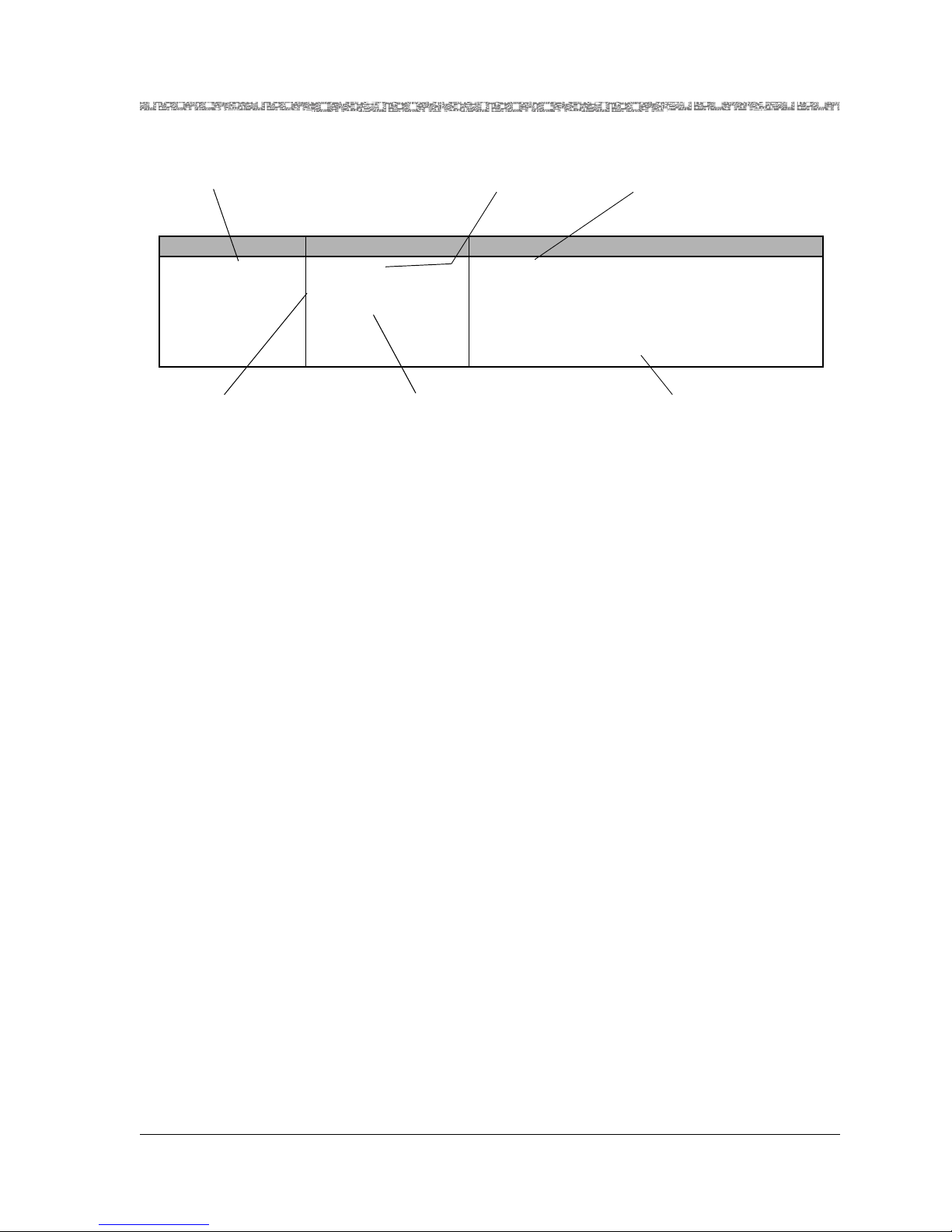
Identifies editable fields
or display-only fields on
screens
Identifies initial field
value default
Identifies available
range for field value
when applicable
Identifies field value format as
Numeric, Predefined,
Hexadecimal, Alphanumeric
Describes special instructions or
configuration constraints
Field Name Field Value Description
The end-to-end connection protocol used.
For MD DS1 module configuration, select the X
value.
Note: DBCES is only available when channeliza-
tion and signalling are enabled on the X window.
Default: 0
Range: 0–22
Format: Numeric
Interface Type
Table 1-4. Field Description Table Example
Describes the function of the field
and special instructions for
configuring modules
Page 26

Chapter 1 Getting Started
Conventions
1-8 255-700-379
PacketStar
®
PSAX 12-Port Medium-Density DS1/E1/DS0A CES Module User Guide (DS1 Mode), Issue 1 Release 8.0.0
• To navigate through the Console windows, use the shortcuts listed in
Table 1-6.
On all the PSAX system windows, each command or menu option has an
underlined letter. The control key plus an underlined letter is a shortcut to
that command or menu option. You can use the navigation keys and hotkeys
with the Caps Lock key on or off. Always observe the status line at the bottom of the window for instructions and information.
Table 1-5. System Responses to Selecting Options, Fields, or Commands
For a
selected...
the following occurs:
option name The window corresponding to the option name is displayed.
field The following variations occur:
• The field entry area is blank or contains the default or previously
entered value. Press Enter to enter or change data in this field. Press
Enter again to exit edit mode.
• The field entry area, like the field name, is displayed in reverse video
image and contains a predefined set of values, which you can view or
select by pressing Enter to navigate forward through these values. To
navigate backward through these field values, press Ctrl+H or the
Backspace key.
Read-only fields, which you cannot change, are enclosed in square
brackets (example: [LineStatus]).
command The following variations occur:
• A message in the information line indicating an error or successful
completion of the command is displayed.
• The next higher level or previous window (window name) is displayed.
• The next lower level or succeeding window (window name) is
displayed.
Table 1-6. Shortcut Keys for Navigating Console Interface Windows
If you want to... press...
redisplay the previous window Ctrl+B on the window.
redisplay the Console Interface Main Menu
window
Ctrl+G on the window.
refresh the window Ctrl+R on the window.
Page 27
255-700-379 1-9
PacketStar
®
PSAX 12-Port Medium-Density DS1/E1/DS0A CES Module User Guide (DS1 Mode), Issue 1 Release 8.0.0
Chapter 1 Getting Started
Help Information
Help Information
The Help windows are accessible from any window in the PSAX system console interface. To access the Help windows, press the ? (Question Mark) key
on any window. In addition to the Help windows, the Console Interface windows display contextual help in the information line at the bottom of each
window. Contextual help provides information about the command or field
currently highlighted on that window. The information line also displays
error codes and responses to commands. All responses and notifications are
recorded in a trap log. See Appendix A in the appropriate PacketStar PSAX
Multiservice Media Gateway user guide for details on displaying the trap log
and explanations of the trap messages.
To view the Help windows from the Console Interface Main Menu window,
perform the following procedure.
Begin
Viewing and Navigating the Help Windows
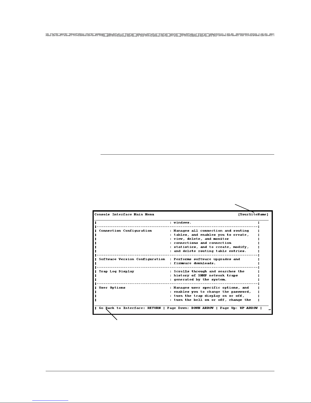
1 On the window for which help is desired, press the ? (question mark)
key.
The Help window for the current console window is displayed (see
Figure 1-1).
2 To display the remaining Help windows for the current console window,
press the Down Arrow key.
Figure 1-1. Main Menu Help Window
Your site name appears here
after initial configu ration
Information line
Page 28

Chapter 1 Getting Started
Technical Support
1-10 255-700-379
PacketStar
®
PSAX 12-Port Medium-Density DS1/E1/DS0A CES Module User Guide (DS1 Mode), Issue 1 Release 8.0.0
3 To scroll backward through the Help windows for the current console
window, press the Up Arrow key.
4 To exit Help and return to the current console window, press the Enter
key.
En
d
Technical Support
If you experience a problem with your PSAX system, refer to the Lucent Technologies InterNetworking Systems Global Warranty, which accompanied your
shipment, for instructions on obtaining support in your area.If you experience a problem with the 12-Port Medium-Density DS1/E1/DS0A CES module, refer to the Lucent Technologies InterNetworking Systems Global Warranty,
which accompanied your shipment, for instructions on obtaining support in
your area.
Comments on This Guide
To comment on the PacketStar® 12-Port Medium-Density DS1/E1/DS0A CES Mod-
ule User Guide (DS1 Mode), please complete the comment card that accompa-
nied your shipment and mail it to the following address:
Senior Manager, Information Design and Development Team
Lucent Technologies
PacketStar PSAX Products
8301 Professional Place
Landover, MD 20785
USA
You can also fax the comment card to us at: 301-809-4540.
Before You Beg i n
Before you start configuring and using your new 12-Port Medium-Density
DS1/E1/DS0A CES module (DS1 mode), be sure you:
• Record your site-specific specifications such as the IP addresses you will
use, and the connections and interfaces you will need. Decide which user
names and passwords you will assign.
• Make sure you have IP connectivity to all PSAX devices to be managed
• Determine the numbering scheme for the in-band connections you will be
using
Page 29
PacketStar
®
PSAX 12-Port Medium-Density DS1/E1/DS0A CES Module User Guide (DS1 Mode), Issue 1 Release 8.0.0
255-700-379 2-1
2 Module Description
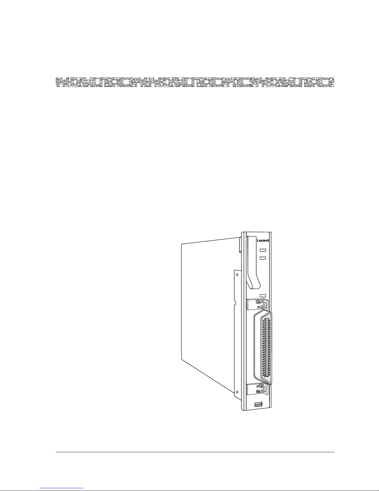
Overview of This Module
The 12-Port Medium-Density DS1/E1/DS0A CES module (Figure 2-1) provides DS1 circuit emulation services, including a new Nx64 Kbps CAS mode
to support channelized AAL1 tariff services. It also provides a line rate of
1.544 Mbps per DS1 port. Each port can be independently configured to pro-
vide Nx64 Kbps (fractional T1) structured, channelized and unchannelized
circuit emulation service (CES) with Nx64 Kbps CAS,integrated services digital network with a primary rate interface (ISDN PRI) service, and unstructured CES. For a description of the 12-Port Medium-Density DS1/E1/DS0A
CES module when it is configured in the DS0A mode, see the PacketStar
®
PSAX 12-Port Medium-Density DS1/E1/DS0A CES Module User Guide (DS0A Mode),
255-700-378.
Note: The E1 signaling mode is not currently supported.
Figure 2-1. 12-Port Medium-Density DS1/E1/DS0A CES Module
ACTIVE
FAIL
LOS
MD DS1/
E1/DS0A
CES
PORTS 1-12
Page 30
Chapter 2 Module Description
Connection Options
2-2 255-700-379
PacketStar
®
PSAX 12-Port Medium-Density DS1/E1/DS0A CES Module User Guide (DS1 Mode), Issue 1 Release 8.0.0
When configured for DS1 circuit emulation service, the module interfaces
with TDM channelized DS1 circuits. It converts channelized data (usually
voice data) to ATM virtual channels. By using structured (channelized) circuit emulation, this module can adapt a maximum of 24 DS0 channels per
port to ATM virtual channels with individual VPIs and VCIs. Signaling bit
transport is also provided, based on ATM Forum standards for CAS.With the
Nx64 Kbps clear channel capability, this module can connect to a device
using an ISDN PRI service.
Because this structured circuit emulation service
can be configured to use only a fraction of the time slots, you can configure
several independent emulated circuits to share one service interface.
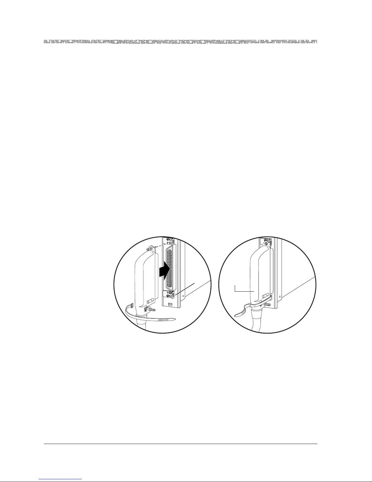
Connection Options
The 12-Port Medium-Density DS1/E1/DS0A CES module connects to user
equipment via a shielded 10-foot Lucent cable assembly (COMCODE
300468030) and a PSAX patch panel. An equivalent shielded cable with an
RJ-48H connector (for example, a Cinch p/n 57-10500-7, 90
o
plug, a Cinch
p/n 57-30500-4, 180
o
plug, a Cinch p/n 57-10500-271, 270o plug, or equivalent) on one end may also be used. Cable connector screws and cable tie
wraps are provided in a kit with the module. See Figure 2-2 for an illustration of this connection.
The Lucent cable is used to connect the module to one of the following patch
panels:
• 12-Port BNC Patch Panel (COMCODE 300298569)
(E1 mode only)
• 24-Port RJ Patch Panel (COMCODE 300298551)
• 48-Port RJ Patch Panel (COMCODE 300298544).
Note: The Telco connector on this module is not the same as the Mini-
Champ connector on the 12-Port Medium-Density DS1 Multiservice module and the 12-Port Medium-Density DS1 IMA module.
Figure 2-2. 12-Port MD DS1/E1/DS0 A CE S M odul e Cable Connection (with Cinch
connector)
Cinch p/n
57-10500-7
90 Plug
o
Connector
Tie
Bracket
with Hole
Page 31

255-700-379 2-3
PacketStar
®
PSAX 12-Port Medium-Density DS1/E1/DS0A CES Module User Guide (DS1 Mode), Issue 1 Release 8.0.0
Chapter 2 Module Description
Connection Options
Figure 2-3 and Figure 2-4 show the connectors of two modules connected to
a 24-port RJ Patch Panel (COMCODE 300298551).
Figure 2-5 and Figure 2-6 show the connectors of four modules connected to
a 48-port RJ Patch Panel (COMCODE 300298551).
Figure 2-3. 12-Port Medium-Density DS1/E1/DS0A CES Modules Connected to
24-port RJ Patch Panel (Telco frame with modules)
Figure 2-4. 12-Port Medium-Density DS1/E1/DS0A CES Modules Connected to
24-port RJ Patch Panel (Telco frame with patch panel)
FAIL
non-redundant
Power Supply
( AC )
DANGER:
HIGH VOLTAGE
WARNINGS:
SEE INSTALLATION
INSTRUCTIONS BEFORE
CONNECTING THIS MODULE
ENSURE FACILITY POWER
IS COMPATIBLE WITH
VOLTAGE RATING OF
THIS MODULE
ATTACH POWER
CORD ONLY
WHEN UNIT IS
FULLY SEATED
IN CHASSIS
UNPLUG POWER CORD
BEFORE REMOVING
THIS MODULE
MULTIPLE POWER
CONNECTIONS,
DISCONNECT TWO
POWER CORDS
BEFORE SERVICING
CHASSIS
ACTIVE
FAIL
non-redundant
Power Supply
( AC )
WARNINGS:
SEE INSTALLATION
INSTRUCTIONS BEFORE
CONNECTING THIS MODULE
ENSURE FACILITY POWER
IS COMPATIBLE WITH
VOLTAGE RATING OF
THIS MODULE
ATTACH POWER
CORD ONLY
WHEN UNIT IS
FULLY SEATED
IN CHASSIS
UNPLUG POWER CORD
BEFORE REMOVING
THIS MODULE
MULTIPLE POWER
CONNECTIONS,
DISCONNECT TWO
POWER CORDS
BEFORE SERVICING
CHASSIS
ACTIVE
ACTIVE
STRATUM
3 4
FAIL
CLK LOS
ACTIVE
STRATUM
3 4
FAIL
ACTIVE
CPU2
FAIL
ETHERNET
CONSOLE
LOAD
ACTIVE
CPU2
FAIL
LOAD
ACTIVE
DS3
ATM
FAIL
LOS
TX
RX
LOS
TX
RX
ACTIVE
DS3
ATM
FAIL
LOS
TX
RX
LOS
TX
RX
ACTIVE
DS3
ATM
FAIL
LOS
TX
RX
LOS
TX
RX
ACTIVE
DS1
IMA
FAIL
LOS
1
6
5
4
3
2
ACTIVE
DS1
IMA
FAIL
LOS
1
6
5
4
3
2
ACTIVE
DS1
IMA
FAIL
LOS
1
6
5
4
3
2
ACTIVE
DS1
IMA
FAIL
LOS
1
6
5
4
3
2
ACTIVE
FAIL
5
3
1
6
4
2
ACTIVE
FAIL
ACTIVE
HD E1 SERIAL
FAIL
DANGER:
HIGH VOLTAGE
CLK LOS
ETHERNET
CONSOLE
PORTS 1-12PORTS 13-21
ACTIVE
HD E1
FAIL
PORTS 1-12PORTS 13-21
ACTIVE
MD DS1/
E1/DS0A
CES
FAIL
PORTS 1-12
LOS
ACTIVE
MD DS1/
E1/DS0A
CES
FAIL
PORTS 1-12
LOS
Connector
Tie
Bracket
with Hole
PacketStar PSAX 75PP12
Page 32

Chapter 2 Module Description
Connection Options
2-4 255-700-379
PacketStar
®
PSAX 12-Port Medium-Density DS1/E1/DS0A CES Module User Guide (DS1 Mode), Issue 1 Release 8.0.0
These patch panels are separately orderable. See the PSAX Patch Panels for
PSAX Multiservice Media Gateways Installation Guide, 255-700-117, for instruc-
tions. Further connections to user equipment may be made per the specifications outlined in ANSI T1.403-1999. See Appendix A, “Pin Configurations,”
for more details.
Figure 2-5. 12-Port Medium-Density DS1/E1/DS0A CES Modules Connected to
48-port RJ Patch Panel (Telco frame with modules)
Figure 2-6. 12-Port Medium-Density DS1/E1/DS0A CES Modules Connected to
48-port RJ Patch Panel (Telco frame with patch panel)
FAIL
non-redundant
Power Supply
( AC )
DANGER:
HIGH VOLTAGE
WARNINGS:
SEE INSTALLATION
INSTRUCTIONS BEFORE
CONNECTING THIS MODULE
ENSURE FACILITY POWER
IS COMPATIBLE WITH
VOLTAGE RATING OF
THIS MODULE
ATTACH POWER
CORD ONLY
WHEN UNIT IS
FULLY SEATED
IN CHASSIS
UNPLUG POWER CORD
BEFORE REMOVING
THIS MODULE
MULTIPLE POWER
CONNECTIONS,
DISCONNECT TWO
POWER CORDS
BEFORE SERVICING
CHASSIS
ACTIVE
FAIL
non-redundant
Power Supply
( AC )
WARNINGS:
SEE INSTALLATION
INSTRUCTIONS BEFORE
CONNECTING THIS MODULE
ENSURE FACILITY POWER
IS COMPATIBLE WITH
VOLTAGE RATING OF
THIS MODULE
ATTACH POWER
CORD ONLY
WHEN UNIT IS
FULLY SEATED
IN CHASSIS
UNPLUG POWER CORD
BEFORE REMOVING
THIS MODULE
MULTIPLE POWER
CONNECTIONS,
DISCONNECT TWO
POWER CORDS
BEFORE SERVICING
CHASSIS
ACTIVE
ACTIVE
STRATUM
3 4
FAIL
CLK LOS
ACTIVE
STRATUM
3 4
FAIL
ACTIVE
CPU2
FAIL
ETHERNET
CONSOLE
LOAD
ACTIVE
CPU2
FAIL
LOAD
ACTIVE
DS3
ATM
FAIL
LOS
TX
RX
LOS
TX
RX
ACTIVE
DS3
ATM
FAIL
LOS
TX
RX
LOS
TX
RX
ACTIVE
DS3
ATM
FAIL
LOS
TX
RX
LOS
TX
RX
ACTIVE
DS1
IMA
FAIL
LOS
1
6
5
4
3
2
ACTIVE
DS1
IMA
FAIL
LOS
1
6
5
4
3
2
ACTIVE
DS1
IMA
FAIL
LOS
1
6
5
4
3
2
ACTIVE
DS1
IMA
FAIL
LOS
1
6
5
4
3
2
ACTIVE
FAIL
5
3
1
6
4
2
ACTIVE
FAIL
ACTIVE
HD E1 SERIAL
FAIL
DANGER:
HIGH VOLTAGE
CLK LOS
ETHERNET
CONSOLE
PORTS 1-12PORTS 13-21
ACTIVE
HD E1
FAIL
PORTS 1-12PORTS 13-21
ACTIVE
MD DS1/
E1/DS0A
CES
FAIL
PORTS 1-12
LOS
ACTIVE
MD DS1/
E1/DS0A
CES
FAIL
PORTS 1-12
LOS
ACTIVE
MD DS1/
E1/DS0A
CES
FAIL
PORTS 1-12
LOS
ACTIVE
MD DS1/
E1/DS0A
CES
FAIL
PORTS 1-12
LOS
Connector
Tie
Bracket
with Hole
PacketStar PSAX 75PP12
Page 33

255-700-379 2-5
PacketStar
®
PSAX 12-Port Medium-Density DS1/E1/DS0A CES Module User Guide (DS1 Mode), Issue 1 Release 8.0.0
Chapter 2 Module Description
Software Features
Software Features
The 12-Port Medium-Density DS1/E1/DS0A CES (DS1 Mode) module supports the following services:
• Circuit emulation service (CES):
~ Structured DS1 signal transport
~ Nx64 Kbps circuit emulation (where 1<=N<=24)
~ Channel-associated signaling (CAS) Nx64
• Integrated services digital network with primary rate interface service (PRI
ISDN) with 64 Kbps clear channel capability for the D-channel
• AAL2 cell formatting for interworking with the DSP2A, DSP2B, DSP2C,
and DSP2D Voice Server modules.
Hardware Features
The 12-Port Medium-Density DS1/E1/DS0A CES (DS1 Mode) module provides the following hardware features:
• Number of ports: 12
• Connector type: one 25-pair, 100-ohm, RJ-48H, 50-pin Telco connector
(receptacle) (see Appendix A for pinouts)
• Line rate: 1.544 Mbps
• Physical interfaces supported: ANSI T1.403; ITU-T G.703, ITU G.704
• Line encoding mode: B8ZS, AMI
• Loopback capabilities: line loopback, local loopback, payload loopback
• Line buildout: Up to 133, 266, 399, 533, and 655 feet; - 7dB through -5dB,
-15dB, and -22dB through -5dB
• Framing mode: ESF, D4
• Transmit clock: local timing, loop timing
• Pulse: meets pulse shape mask of ANSI T1.403
Hardware Specifications
Table 2-1 shows the general physical hardware and environmental specifications for the PacketStar PSAX I/O and server modules.
Page 34

Chapter 2 Module Description
Software Features
2-6 255-700-379
PacketStar
®
PSAX 12-Port Medium-Density DS1/E1/DS0A CES Module User Guide (DS1 Mode), Issue 1 Release 8.0.0
Performance and Power Specifications
Table 2-2 describes the chassis speed, power consumption, and memory allocation specifications for this module.
Table 2-1. Physical Hardware Specifications
Specification Description
Dimensions 17.3 cm H x 2.41 cm W x 23.2 cm D
(6.8 in. H x 0.95 in. W x 9.13 in. D)
Weight 0.45 kg (1.0 lb.)
Operating temperature range
for AC-powered PSAX 1000 and all
PSAX 1250, PSAX 2300, and
PSAX 4500 systems
0° to 50° C (32° to 122° F)
Operating temperature range for
DC-powered PSAX 1000 systems
-20° to 60° C (-4° to 140° F) with a cold start
minimum of 0° C (32° F)
Operating humidity range 5% to 85% relative humidity
Operating altitude range 197 feet below sea level to 13,123 feet above
sea level
Storage temperature range -40° to 70° C (-40° to 158° F)
Storage humidity range 0 to 90% noncondensing
Table 2-2. Performance and Power Specifications for the 12-Port Medium-Density DS1/E1/DS0A CES
Module
Module
Total
Amount of
SDRAM
Module
Program and
Data Space
Maximum
Input
Buffer
*
Output
Buffer
†
Chassis
Speed
‡
Power
Consumption
12-Port Medium-Density DS1/E1/DS0A CES
(
MD DS1/E1/DS0A CES)
8 MB 8 MB 2 cells/
port
16 cells/
port
High
Speed
11.5 W
*
The I/O buffers carry 16,384 cells per megabyte.
†
Indicates the size of the output buffer.
‡
This column relates only to the speed at which the modules communicate within the chassis. A high-speed module will communicate at high speed (1.23 Gbps) in a chassis that has a
high-speed bus (PSAX 4500 chassis). High-speed modules will communicate at 650 Mbps in
any other chassis. Low-speed modules will always communicate at 650 Mbps in any chassis.
Page 35

255-700-379 2-7
PacketStar
®
PSAX 12-Port Medium-Density DS1/E1/DS0A CES Module User Guide (DS1 Mode), Issue 1 Release 8.0.0
Chapter 2 Module Description
Software Features
Module Placement
The 12-Port Medium-Density DS1/E1/DS0A CES module is installed in any
PSAX chassis slot intended to contain an I/O or server module. If you are
installing the module in a newly installed PSAX chassis, be sure to follow
your facility site plan for placing this module in the correct location in the
chassis.
Note: When operating this module in the DS0A mode, the Stratum 3–4
module you use in the PSAX 1250 chassis should be one with the
PEC NS20N053DC and COMCODE 300412699, or a subsequent
model.
LED Indicators
Table 2-3 describes how the LED indicators on the 12-Port Medium-Density
DS1/E1/DS0A CES module faceplate respond to different module conditions.
These LEDs indicate if the module is installed and operating properly.
Page 36

Chapter 2 Module Description
Software Features
2-8 255-700-379
PacketStar
®
PSAX 12-Port Medium-Density DS1/E1/DS0A CES Module User Guide (DS1 Mode), Issue 1 Release 8.0.0
Table 2-3. LED Indicators for the 12-Port Medium-Density DS1/E1/DS0A CES
Module
Initial
Power-On
No
Configured
Ports
One or More
Configured
Ports
No Cable on
Port
Cable on
Port
FAIL
(red)
Lights
briefly
1
Not lit Lights only
when the
module is
not functioning
N/A N/A
ACTIVE
(green)
Lights
briefly
1
Not lit Lights only
when the
module is
functioning properly
N/A N/A
LOS
[Loss of
Signal]
(yellow)
Lights
briefly
2
N/A Lights only
when a
port is configured and
no signal is
received
Lights • Does not
light if signal is being
received
• Lights if
signal is
missing
1
Note: After power is initially applied to the system and the system boot is
complete, the FAIL and ACTIVE LEDs indicate whether the module has no
configured ports (red), or one or more configured ports (green).
2
Note: After power is initially applied to the system and the system boot is
complete, this loss of signal LED indicates whether the port has a cable connected to it.
LED
Module
Status
Page 37

Part 2: Console Operation
Page 38

Page 39

PacketStar
®
PSAX 12-Port Medium-Density DS1/E1/DS0A CES Module User Guide (DS1 Mode), Issue 1 Release 8.0.0
255-700-379 3-1
3 Configuring Ports and Channels
Using the Console
Overview of This Chapter
This chapter describes how to configure ports and channels for the 12-Port
Medium-Density DS1/E1/DS0A CES module module (DS1 mode) on the
PSAX Multiservice Media Gateway system console interface.
Loopback Configuration Options
To aid network troubleshooting and testing, loopback capability is provided
for the 12-Port Medium-Density DS1/E1/DS0A CES module module(DS1
mode). The loopback option on the module port and channel configuration
window enables you to verify the integrity of a port by transmitting a
received signal back to the source. Selecting a loopback option is described in
the module configuration procedure provided in this chapter.
Figure 3-1 illustrates the line loop, payload loop, and local loop options.
Figure 3-1. Loopback Configuration Options
Local Loop
Line Driver
Receiver
Port
Connector
Backplane
Connector
Line Driver
Receiver
Backplane
Connector
Line Loop
Signal
Port Connector
Framing Chip
Payload Loop
Backplane
Connector
Page 40

Chapter 3 Configuring Ports and Channels Using the Console
Configuring the Module
3-2 255-700-379
PacketStar
®
PSAX 12-Port Medium-Density DS1/E1/DS0A CES Module User Guide (DS1 Mode), Issue 1 Release 8.0.0
Configuring the Module
The 12-Port Medium-Density DS1/E1/DS0A CES module module (DS1
mode) has 12 physical ports, which may be used for DS1 circuit emulation
services. You must first configure the 12-Port Medium-Density DS1/E1/DS0A
CES module module (DS1 mode) before setting up connection provisioning.
To configure ports and channels for the 12-Port Medium-Density
DS1/E1/DS0A CES module in the DS0A Mode, see the PacketStar
®
PSAX 12-
Port Medium-Density DS1/E1/DS0A CES (DS0A Mode) Module User Guide, 255-
700-378.
Note: The E1 mode is not supported in this release.
Configuring Ports and Channels in the DS1 Mode
To configure the 12-Port Medium-Density DS1/E1/DS0A CES module module ports and channels in the DS1 mode, perform the steps in the following
procedure.
Begin
Configuring the Ports and Channels
1 On the Console Interface Main Menu window (see Figure 3-2), select
the Equipment Configuration option and press Enter.
The Equipment Configuration window is displayed (see Figure 3-3 and
Figure 3-4).
Figure 3-2. Console Interface Main Menu Window (Equipment Configuration
Selected)
Page 41

255-700-379 3-3
PacketStar
®
PSAX 12-Port Medium-Density DS1/E1/DS0A CES Module User Guide (DS1 Mode), Issue 1 Release 8.0.0
Chapter 3 Configuring Ports and Channels Using the Console
Configuring the Module
2 Select Page Down to display page 2 of this window (Figure 3-4).
Figure 3-3. Equipment Configuration Window (As Displayed on the PSAX 1250,
PSAX 2300, and PSAX 4500 Console, Page 1)
Figure 3-4. Equipment Configuration Window (As Displayed on the PSAX 1250,
PSAX 2300, and PSAX 4500 Console, Page 2 )
Page 42

Chapter 3 Configuring Ports and Channels Using the Console
Configuring the Module
3-4 255-700-379
PacketStar
®
PSAX 12-Port Medium-Density DS1/E1/DS0A CES Module User Guide (DS1 Mode), Issue 1 Release 8.0.0
3 On the Equipment Configuration window, select an MD–DS1E1DS0A
module in the Card Type column and press Enter. The 12-Port MediumDensity DS1 Port Configuration window is displayed (see Figure 3-5).
This window allows you to select a physical port (1–12) to configure. It
also provides the operational status of the channels and interfaces for
each port.
Commands The commands in this window have the following functions:
Figure 3-5. 12-Port Medium-Density DS1 Port Configuration Window
Command Function
Apply Operating Mode
Change
Changes the mode in which the module
will operate. After changing the value to
DS1 or DS0A in the Operating Mode
field, select this command to apply the
change. The module reboots and the window reflects your selection.
Note: All interfaces must be unconfig-
ured, out of service, and deleted before
using this command.
Update Display Updates the values in the fields to show
the most current configuration. Use this
command to display the most current
information in the Line Status field.
Page 43

255-700-379 3-5
PacketStar
®
PSAX 12-Port Medium-Density DS1/E1/DS0A CES Module User Guide (DS1 Mode), Issue 1 Release 8.0.0
Chapter 3 Configuring Ports and Channels Using the Console
Configuring the Module
Field Descriptions The fields in this window are described in Table 3-1.
Delete All Interfaces Deletes the configured interfaces for the
12 ports. You must take all interfaces out
of service (using the Take All Interfaces
Out Of Service command) before you
can use this command to delete all the
configured interfaces.
Bring All Interfaces Into
Service
Brings the out-of-service configured interfaces for the 12 ports to in-service status.
Take All Interfaces Out Of
Service
Takes the in-service configured interfaces
for the 12 ports to out-of-service status.
You must use this command first before
using the Delete All Interfaces command.
Go Back to Equipment Configuration
Redisplays the Equipment Configuration
window.
Command Function
Table 3-1. Field Descriptions for the 12-Port Medium-Density DS1 Port Configuration Window
Field Name Field Values Description
Slot: nn Default: N/A
Range: Variable
Format: Numeric
The PSAX chassis slot that the selected module
occupies.
Port
(display only)
Default: N/A
Range: 1-12
Format: Numeric
The physical port on the module.
# Channels
Configured
(display only)
Default: 0
Range: 1-24
Format: Numeric
The number of channels configured for this port.
# Interfaces
In Service
(display only)
Default: 0
Range: 1-24
Format: Numeric
The number of interfaces configured for this port
that are operationally in service.
Line Status
(display only)
Default: No Alarm
Range: N/A
Format: Predefined
The alarm status of the physical port. Displays the
most current information when a trap message is
received or when the Update Display command
is selected.
Note: Shows No Alarm when no interfaces are
configured.
Operating Mode Default: DS1
Range: DS1, DS0A
Format: Predefined
Allows you to change the operating mode value
to DS1 or DS0A. Select the Apply Operating
Mode Change command to apply the change.
Note: All interfaces must be unconfigured, out of
service, and deleted before changing the
operating mode.
Page 44

Chapter 3 Configuring Ports and Channels Using the Console
Configuring the Module
3-6 255-700-379
PacketStar
®
PSAX 12-Port Medium-Density DS1/E1/DS0A CES Module User Guide (DS1 Mode), Issue 1 Release 8.0.0
4 Select the line with the port you want to configure. The 12-Port
Medium-Density DS1 Port and Channel Configuration window is displayed (see Figure 3-6).
Commands The commands in this window have the following functions:
Figure 3-6. 12-Port Medium-Density DS1 Port and Channel Configuration
Window (Channelization Disabled)
Command Function
Delete Interfaces:
through
Deletes a selected range of configured interfaces
when channelization has been enabled. Select
the command and follow the prompts to enter
the channel numbers and delete the selection.
Note: This command does not display when
channelization has been disabled.
Note: You must first take the configured inter-
faces that are in-service to out-of-service (using
the Take All Interfaces Out Of Service com-
mand) before you can use this command.
Show Straps Displays the 12-Port Medium-Density DS1 DS0s
Strap Display window.
Apply Port Configuration
For the current port, applies the port configuration field values.
Reset Display Resets the port configuration fields to the last set
of saved values.
Page 45

255-700-379 3-7
PacketStar
®
PSAX 12-Port Medium-Density DS1/E1/DS0A CES Module User Guide (DS1 Mode), Issue 1 Release 8.0.0
Chapter 3 Configuring Ports and Channels Using the Console
Configuring the Module
Field Descriptions 5 Enter values in the fields on this window according to the information
provided in Table 3-2.
View Port Statistics Displays the 12-Port Medium-Density DS1 Port
Statistics window.
Delete All Interfaces
On This Port
Deletes the configured interface and sets the
channel to unconfigured status. The value
Unconfigured displays in the Chnl Status field.
Note: You must first take the interface that is in-
service to out-of-service (using the Take All
Interfaces Out Of Service command) before
you can use this command.
Bring All Interfaces
Into Service
Brings the out-of-service configured interface
for the channel to administrative in-service status. An asterisk displays beside all the configured channels when they are administratively
or operationally out-of-service.
Note: You must first configure the interface
before you can use this command.
Take All Interfaces Out
Of Service
Takes the in-service configured interface to outof-service status. An asterisk displays beside all
the configured channels when they are administratively or operationally out-of-service.
Note: You must use this command first before
using the Delete All interfaces On This Port
command.
Go Back to Card Configuration
Redisplays the 12-Port Medium-Density DS1
Port Configuration window.
Command Function
Table 3-2. Field Descriptions for the 12-Port Medium-Density DS1 Port and Channel Configuration
Window
Field Name Field Values Description
Line Type Default: Esf
Range: N/A
Format: Predefined
Indicates the framing mode to be used on this
port.
Note: When you select the value Unstructured
in the Data Tx Type field, the Line Type field dis-
appears.
Esf Extended Super Frame DS1 format.
D4 D4 format.
Page 46

Chapter 3 Configuring Ports and Channels Using the Console
Configuring the Module
3-8 255-700-379
PacketStar
®
PSAX 12-Port Medium-Density DS1/E1/DS0A CES Module User Guide (DS1 Mode), Issue 1 Release 8.0.0
Line Coding Default: B8ZS
Range: N/A
Format: Predefined
Indicates the type of line coding to be used on
this port. (The data format that lets either end of
the communications channel correctly interpret
messages from the other.)
B8ZS Bipolar with 8 zero substitution. Indicates the use
of a specified pattern of normal bits and bipolar
violations to replace sequence of 8 zero bits.
Ami Alternate mark inversion. Indicates zero code
suppression.
Loopback Default: NoLoop
Range: N/A
Format: Predefined
Indicates whether the port is to be used for loopback testing and, if so, the type of loopback to be
performed.
NoLoop Indicates that the port will not be used for loop-
back.
LocalLoop Indicates that local loopback will be used on this
port. The signal will be received from another
module in the chassis, sent through the module
circuitry (including the SAR function) and the
chassis backplane to the originating module.
LineLoop Indicates that line loop will be used on this port.
The received signal will be sent through the
receiver and the line driver, and then back out to
the originating point.
PayloadLoop Indicates the received signal is sent through the
framing chip on the module, but not on the SAR
circuitry, and then back out to the originating
point. The data link is regenerated.
Transmit Clock Default: Local
Timing
Range: N/A
Format: Predefined
Indicates the timing source to be used on this
port. The timing source is a signal that provides a
timing reference for a transmission link.
LocalTiming Indicates that local clock source will be used as
the timing source.
LoopTiming Indicates that recovered receive clock is used as
the timing source.
Adaptive Timing Monitors the port buffers to increase or decrease
the transmission rate. Displays only when the
port is configured as Unstructured in the Data
Transfer Type field.
Table 3-2. Field Descriptions for the 12-Port Medium-Density DS1 Port and Channel Configuration
Window
Field Name Field Values Description
Page 47

255-700-379 3-9
PacketStar
®
PSAX 12-Port Medium-Density DS1/E1/DS0A CES Module User Guide (DS1 Mode), Issue 1 Release 8.0.0
Chapter 3 Configuring Ports and Channels Using the Console
Configuring the Module
Line Build Out Default: UpTo133
Feet
Range: N/A
Format: Predefined
Indicates the selectable output attenuation.
UpTo133Feet Indicates the DS1 signal level is transmitted to be
received from 0 to 133 f eet
UpTo266Feet Indicates the DS1 signal is transmitted to be
received from 0 to 266 feet
UpTo399Feet Indicates the DS1 signal is transmitted to be
received from 0 to 399 feet
UpTo533Feet Indicates the DS1 signal is transmitted to be
received from 0 to 533 feet
UpTo655Feet Indicates the DS1 signal is transmitted to be
received from 0 to 655 feet
negative7-5Db Indicates the T1 signal level range at which the
DS1 is configured is negative 7.5 dB
negative15Db Indicates the T1 signal level range at which the
DS1 is configured is negative 15 dB
negative22-5Db Indicates the T1 signal level range at which the
DS1 is configured is negative 22.5 dB
Data Tx Type (Data
Transfer Type)
Default: Structured
Range: N/A
Format: Predefined
Indicates whether this port has structured or
unstructured interfaces.
Structured Indicates that this port supports Nx64 Kbps
channelized interfaces.
Unstructured Indicates that this port has unstructured
(unchannelized) interfaces.
Note: When you select this value, the Line Type,
Channelization, and UpStrmIntrworking fields
disappear.
Table 3-2. Field Descriptions for the 12-Port Medium-Density DS1 Port and Channel Configuration
Window
Field Name Field Values Description
Page 48

Chapter 3 Configuring Ports and Channels Using the Console
Configuring the Module
3-10 255-700-379
PacketStar
®
PSAX 12-Port Medium-Density DS1/E1/DS0A CES Module User Guide (DS1 Mode), Issue 1 Release 8.0.0
Channelization Default: Disabled
Range: N/A
Format: Predefined
Indicates whether the DS1 port is divided into 24
channels.
Note: When you select the value Unstructured
in the Data Tx Type field, the Channelization field
disappears.
Disabled Indicates that the division of the DS1 port into 24
channels is disabled. Use this setting if you want
to set up only one channel for the port. When
you select the Apply Port Configuration com-
mand, only channel 1 displays the value Uncon-
figured.
Enabled Indicates that the division of the DS1 port into 24
channels is enabled. Use this setting if you want
to set up more than one channel for the port.
UpStrm
Intrworking
Default: TrunkCond
Range: N/A
Format: Predefined
Displays the communications mode selected
between the CE and ATM sides of a connection
on this port during alarm conditions.
Note: When you select the value Unstructured
in the Data Tx Type field, the UpStrmInter
working field disappears.
TrunkCond Indicates that trunk conditioning will be done for
each channel of this port whose corresponding
ATM side is alarmed. This improves the communication of the trunk status for TDM traffic. See
the PacketStar PSAX Multiservice Media Gateway
Trunk Conditioning Application Note for more
details.
Unframed1s Indicates that a sequence of unframed all 1’s will
be transmitted to the CES end point whenever
there is an alarm indication signal (AIS) on the
ATM side for any CE to ATM connection on this
port.
SG Feature Default: Disabled
Range: N/A
Format: Character
Displays the status of the connection gateway
feature.
Note: This feature is not supported in this release.
Disabled Indicates that the connection gateway feature is
disabled. See the PacketStar
®
Connection Gateway
API Specification for more details.
Enabled Indicates that the connection gateway feature is
enabled.
[Line Status]
(display only)
Default: NoAlarm
Range: N/A
Format: Character
Indicates the status of the line: NoAlarm,
LossOfSignal, or one of several alarms. See the
line status table for the DS1 mode below.
Table 3-2. Field Descriptions for the 12-Port Medium-Density DS1 Port and Channel Configuration
Window
Field Name Field Values Description
Page 49

255-700-379 3-11
PacketStar
®
PSAX 12-Port Medium-Density DS1/E1/DS0A CES Module User Guide (DS1 Mode), Issue 1 Release 8.0.0
Chapter 3 Configuring Ports and Channels Using the Console
Configuring the Module
The following table shows line status alarms for the 12-Port MD
DS1/E1/DS0A CES module (DS1 mode):
6 To configure channels, perform one of the following procedures:
En
d
Table 3-3. DS1 Line Status Alarms
Bit Value Alarm Description
1 NoAlarm No alarm present
2 RcvFarEndLOF PSAX is receiving an RAI alarm. The RAI (yellow) alarm
is usually sent by the far-end device when an LOS, AIS,
or LOF condtion is detected on its receive port.
4 XmtFarEndLOF Near-end sending LOF indication
8 RcvAIS Far-end sending AIS (red alarm)
16 XmtAIS Near-end sending AIS
32 LossOfFrame Near-end LOF
64 LossOfSignal Near-end loss of signal
128 LoopbackState Near-end is looped
256 T16AIS E1 TS16 AIS (not valid for DS1)
512 RcvFarEndLOMF Far-end sending TS16 LOMF (not valid for DS1)
1024 XmtFarEndLOMF Near-end sending TS16 LOMF (not valid for DS1)
2048 RcvTestCode Near-end detects a test code
4096 OtherFailure Any other line status not shown in this table
8192 RmtLoopback Far-end loopback
Table 3-4. Configuring Channels
If you want to configure... then...
the port as one channel, you must have selected the value
Disabled in the Channelization field
(see Table 3-2). Continue with
instructions in “Configuring a Port
with One Channel”.
several channels for a port, you must have selected the value
Enabled in the Channelization field
(see Table 3-2). Continue with
instructions in ”Configuring a Port
with Several Channels” on
page 3-15.
Page 50

Chapter 3 Configuring Ports and Channels Using the Console
Configuring the Module
3-12 255-700-379
PacketStar
®
PSAX 12-Port Medium-Density DS1/E1/DS0A CES Module User Guide (DS1 Mode), Issue 1 Release 8.0.0
Port with One
Channel
Begin
Configuring a Port with One Channel
To configure one or more ports on the 12-Port Medium-Density DS1/DS0A
CES module with only one channel for a port, proceed as follows:
1 Select 1 Unconfigured on the 12-Port Medium-Density DS1 Port and
Channel Configuration window (see Figure 3-6).
Note: You must have selected the value Disabled in the Channelization
field on the 12-Port Medium-Density DS1 Port and Channel Configuration window.
The Medium Density 12-Port DS1 Channel Configuration window (see
Figure 3-7) is displayed.
Commands
The commands in th is window h ave the following functions:
Figure 3-7. Medium Density 12-Port DS1 Channel Configuration Window (One
Channel per Port)
Command Function
Apply Configuration For a specified port and channel number
value, applies the interface configuration
you selected.
Reset Display Resets the fields to the last set of saved
values.
Bring Interface Into Service Brings the out-of-service configured inter-
face to in-service status. The value
InService is displayed in the [Admin Status] field.
Page 51

255-700-379 3-13
PacketStar
®
PSAX 12-Port Medium-Density DS1/E1/DS0A CES Module User Guide (DS1 Mode), Issue 1 Release 8.0.0
Chapter 3 Configuring Ports and Channels Using the Console
Configuring the Module
Field Descriptions 2 Enter values in the fields on this window according to the information
provided in Table 3-5.
Take Interface Out Of Service
Takes the in-service configured interface
to out-of-service status. The value
OutOfService is displayed in the [Oper
Status] and the [Admin Status] fields.
Configure Interface Displays an interface configuration win-
dow for the selected interface.
Go Back to Port Configuration
Redisplays the 12-Port Medium-Density
DS1 Port and Channel Configuration window.
Command Function
Table 3-5. Field Descriptions for the Medium Density 12-Port DS1 Channel Configuration Window
Field Name Field Values Description
[Slot: nn]
(display only)
Default: N/A
Range: Variable
Format: Numeric
The PSAX chassis slot that the selected module
occupies.
Port: nn Default: N/A
Range: 1-12
Format: Numeric
The physical port on the module.
Channel: nnn Default: 001
Range: 001-024
Format: Numeric
Indicates the channel selected.
Note: Only channel 001 is available when chan-
nelization is disabled.
Interface Type Default:
Unconfigured
Range: N/A
Format: predefined
character
Indicates the type of end-to-end connection protocol that governs the transmission parameters of
the configured channel interface.
Unconfigured This interface is not configured.
CircuitEmulation This interface is configured for the circuit emula-
tion interface.
Signaling Default: Disabled
Range: N/A
Format: Character
Indicates signaling status on the configured interface. When channelization is disabled and
CircuitEmulation is selected, this field is display
only.
Disabled Indicates that signaling is disabled. This interface
uses common channel signaling (Ccs).
Enabled Indicates that signaling is enabled. This interface
uses channel-associated signaling (Cas).
Page 52

Chapter 3 Configuring Ports and Channels Using the Console
Configuring the Module
3-14 255-700-379
PacketStar
®
PSAX 12-Port Medium-Density DS1/E1/DS0A CES Module User Guide (DS1 Mode), Issue 1 Release 8.0.0
3 Select an interface in the Interface Type field.
4 Select the Apply Configuration command.
5 Select the Bring Interface Into Service command.
6 Select the Configure Interface command. The interface configuration
window is displayed.
See Chapter 4, “Configuring the Interfaces Using the Console,” for a
description of this window.
[Admin Status]
(display only)
Default:
Unconfigured
Range: N/A
Format: predefined
character
Displays the administrative status of the selected
channel.
Unconfigured The interface for the channel is not configured.
InService The interface has been brought into service with
the Bring Interface Into Service command.
OutOfService The interface has not yet been brought into ser-
vice, or its in-service interface has been set to out
of service with the Take Interface Out of Ser-
vice command.
[Oper Status]
(display only)
Default:
Unconfigured
Range: N/A
Format: predefined
character
Displays the operational status of the selected
channel and whether the channel is exchanging a
valid signal.
Unconfigured This channel is not operational because the inter-
face is not configured.
InService The configured interface is currently operational,
that is, capable of receiving and sending signals.
OutOfService The configured interface is not currently opera-
tional, that is, not capable of receiving and sending signals, because no connection exists.
[Available DS0s]:
(display only)
Default: N/A
Range: 01-24
Format: numeric
Indicates the number of unchecked DS0s available to be strapped to a particular channel. DS0s
are only available when channelization is
enabled. This field is not displayed when signaling is Enabled.
[DS0s Strapped]
(display only)
Default: N/A
Range: 01-24
Format: numeric
Indicates the number of checked DS0s strapped
to a particular channel. When channelization is
disabled, all 24 DS0s are strapped to channel 001.
Table 3-5. Field Descriptions for the Medium Density 12-Port DS1 Channel Configuration Window
Field Name Field Values Description
Page 53

255-700-379 3-15
PacketStar
®
PSAX 12-Port Medium-Density DS1/E1/DS0A CES Module User Guide (DS1 Mode), Issue 1 Release 8.0.0
Chapter 3 Configuring Ports and Channels Using the Console
Configuring the Module
7 Repeat “Configuring Ports and Channels in the DS1 Mode”, and steps 1-
6 under “Configuring a Port with One Channel” for the remainder of the
ports, as needed.
Note: Be sure to complete the module port and channel configuration
and then the interface configuration for each port before beginning
the configuration of a new port.
8 You can save the values permanently to the Multiservice Media Gate-
way system database now, or before you exit the current session of the
Multiservice Media Gateway system console interface. See “Saving the
Equipment Configuration and Logging Off” on page 3-21.
End
Port with Several
Channels
Begin
Configuring a Port with Several Channels
To configure one or more ports on the 12-Port Medium-Density
DS1/E1/DS0A CES module with several DS0s strapped together in one channel and several channels for a port, proceed as follows:
1 Select 1 Unconfigured on the 12-Port Medium-Density DS1 Port and
Channel Configuration window (see Figure 3-8).
Note: You must have selected the value Enabled in the Channelization
field on this window.
Figure 3-8. 12-Port Medium-Density DS1 Port and Channel Configuration
Window (Channelization Enabled)
Page 54

Chapter 3 Configuring Ports and Channels Using the Console
Configuring the Module
3-16 255-700-379
PacketStar
®
PSAX 12-Port Medium-Density DS1/E1/DS0A CES Module User Guide (DS1 Mode), Issue 1 Release 8.0.0
The Medium Density 12-Port DS1 Channel Configuration window (see
Figure 3-9) is displayed.
See page 3-12 for a description of the commands and fields in this window.
2 Select an interface in the Interface Type field. The Signaling field appears
with the Disabled default value.
3 In the [Available DS0s] field, move the cursor to value 01 (indicates DS0
1) and press Enter to display x below DS0 01.
4 Move the cursor to the next DS0 value and press Enter to display x
below the DS0 value. Select as many DS0s as you want to strap together
for the selected channel.
5 Select the Apply Configuration command.
In the [DS0s Strapped] field (display only), the values for the DS0s you
just selected are displayed.
6 Select the Bring Interface Into Service command.
7 Select the Configure Interface command. The interface configuration
window is displayed.
See Chapter, 5, “Configuring the Interfaces Using the Console,” for a
description of this window.
Note: Be sure to complete the module port and channel configuration
and then the interface configuration for each port before beginning
the configuration of a new port.
8 To strap together DS0s for another channel in the selected port, reselect
the Channel field and enter the next channel number, for example, 002.
Figure 3-9. Medium Density 12-Port DS1 Cha nnel Configuration Windo w (Several
Channels per Port)
Page 55

255-700-379 3-17
PacketStar
®
PSAX 12-Port Medium-Density DS1/E1/DS0A CES Module User Guide (DS1 Mode), Issue 1 Release 8.0.0
Chapter 3 Configuring Ports and Channels Using the Console
Configuring the Module
9 Repeat steps 2-7.
10 To view the strapped DS0s and their associated channels at any time,
select the Show Straps command on the 12-Port Medium-Density DS1
Port and Channel Configuration window (see Figure 3-8). The 12-Port
Medium-Density DS1 DS0s Strap Display window (see Figure 3-10) is
displayed.
Note: The strapped DS0s you set up are displayed next to their associated
channels.
Commands The commands in this window have the following functions:
Field Descriptions The fields in this window are described in Table 3-6.
Figure 3-10. 12-Port Medium-Density DS1 DS0s Strap Display Window
Command Function
Update Display Resets the fields to the last set of saved
values.
Go Back to DS1 Port Configuration
Redisplays the 12-Port Medium-Density
DS1 Port and Channel Configuration window.
Page 56

Chapter 3 Configuring Ports and Channels Using the Console
Configuring the Module
3-18 255-700-379
PacketStar
®
PSAX 12-Port Medium-Density DS1/E1/DS0A CES Module User Guide (DS1 Mode), Issue 1 Release 8.0.0
End
Port Statistics
Begin
Viewing 12-Port Medium-Density DS1 Port Statistics
To view statistics for a port, from the 12-Port Medium-Density DS1 Port and
Channel Configuration window (Figure 3-8), select the View Port Statis-
tics command. The 12-Port Medium-Density DS1 Port Statistics window (see
Figure 3-11) is displayed.
Table 3-6. Field Descriptions for the 12-Port Medium-Density DS1 DS0s Strap Display Window
Field Name Field Values Description
[Slot: nn]
(display only)
Default: N/A
Range: Variable
Format: Numeric
Displays the chassis slot that the selected module
occupies.
Port: nn Default: N/A
Range: 1-12
Format: Numeric
Displays the physical port selected.
Ch
(display only)
Default: N/A
Range: 1-24
Format: Numeric
Displays the channels available.
Note: Only channel 1 is available when channel-
ization is disabled.
DS0s
(display only)
Default: N/A
Range: 1-24
Format: Numeric
Displays the DS0s strapped to a particular channel. When channelization is disabled, all 24 DS0s
are strapped to channel 1.
Page 57

255-700-379 3-19
PacketStar
®
PSAX 12-Port Medium-Density DS1/E1/DS0A CES Module User Guide (DS1 Mode), Issue 1 Release 8.0.0
Chapter 3 Configuring Ports and Channels Using the Console
Configuring the Module
Commands The commands in this window have the following functions:
Field Descriptions The fields in this window are described in Table 3-7.
Figure 3-11. 12-Port Medium-Density DS1 Port Statistics Window
Command Function
Continuous Update Updates the values in the fields every sec-
ond.
Reset Statistics Sets all field values to 0.
Go Back to Port Configuration
Redisplays the 12-Port Medium-Density
DS1 Port and Channel Configuration window.
Page 58

Chapter 3 Configuring Ports and Channels Using the Console
Configuring the Module
3-20 255-700-379
PacketStar
®
PSAX 12-Port Medium-Density DS1/E1/DS0A CES Module User Guide (DS1 Mode), Issue 1 Release 8.0.0
Table 3-7. Field Descriptions for the 12-Port Medium-Density DS1 Port Statistics Window
Field Name Field Values Description
Errored Seconds Default: 0000000000
Range: N/A
Format: numeric
Displays the number of errored seconds that have
occurred on the DS1 port since the last time statistics were reset. For ESF signals, an errored second contains at least one of the following:
• Path coding violation
• Controlled slip event
• Detected alarm indication signal (AIS) defect
• Out-of-frame (OOF) defect
For D4 signals, this field indicates the presence of
bipolar violations
Severely Errored
Seconds
Default: 0000000000
Range: N/A
Format: numeric
Displays the number of severely errored seconds
that have occurred on the DS1 port since the last
time statistics were reset. For ESF signals, a
severely errored second contains at least one of
the following:
• 320 or more path coding violation error events
• OOF defect
• Detected AIS defect
For D4 signals, a severely errored second contains
at least one of the following:
• one-second intervals with framing error events
• OOF defect
• 1,544 or more line coding violations (LCVs)
Severely Errored
Framing Seconds
Default: 0000000000
Range: N/A
Format: numeric
Displays the number of severely errored framing
seconds encountered by the DS1 port in one of
the previous 96 individual 15-minute intervals. A
severely errored framing second has one or more
out-of-frame defects or a detected AIS defect.
Unavailable Seconds
Default: 0000000000
Range: N/A
Format: numeric
Displays the number of unavailable seconds
encountered by the DS1 port in one of the previous 96 individual 15-minute intervals. Unavailable seconds (UAS) are calculated by the number
of seconds that the interface is unavailable.
Controlled Slip Seconds
Default: 0000000000
Range: N/A
Format: numeric
Displays the number of controlled slip seconds
encountered by the DS1 port in the previous
24-hour period. A controlled slip second is a
one-second interval containing one or more controlled slip events.
Path Coding Violations
Default: 0000000000
Range: N/A
Format: numeric
Displays the number of path coding violations
encountered by the DS1 port in the previous
24-hour period. A path coding violation is a
frame synchronization bit error in the D4 and
DS1-no-CRC formats, or a CRC error in the ESF
and DS1-CRC formats.
Page 59

255-700-379 3-21
PacketStar
®
PSAX 12-Port Medium-Density DS1/E1/DS0A CES Module User Guide (DS1 Mode), Issue 1 Release 8.0.0
Chapter 3 Configuring Ports and Channels Using the Console
Saving the Equipment Configuration and Logging Off
Saving the Equipment Configuration and Logging Off
After configuring the module ports and channels, the interface types for each
port and channel, and the connections, you must save the values to the
PSAX system database. It is recommended that you save your values frequently as you progress through your work, at a minimum, after finishing
each stage of work:
• Configuring each module in your system
• Configuring the connections in your system
• Before exiting your current console session
After configuring your basic systemwide values, you must save them to the
PSAX system database. It is recommended that you save your values frequently as you progress through your work.
Perform the following procedure to permanently save the values for your
system.
!
CAUTION:
If your system or location loses power or your current session ends
abnormally while you are in the process of configuring the system, and
you have not yet saved the values permanently, you will lose all unsaved
values you have applied on the various windows.
Line Errored Seconds
Default: 0000000000
Range: N/A
Format: numeric
Displays the number of line errored seconds
encountered by the DS1 port in the previous
24-hour period. A line errored second is a second
in which one or more line code violation error
events were detected.
Bursty Errored Seconds
Default: 0000000000
Range: N/A
Format: numeric
Displays the number of bursty errored seconds
encountered by the DS1 port in the previous
24-hour period. A bursty errored second has
fewer than 320 and more than 1 path coding violation error events, no severely errored frame
defects, and no detected incoming AIS defects.
Line Coding Violations
Default: 0000000000
Range: N/A
Format: numeric
Displays the number of line coding violations that
have occurred on the DS1 port since the last time
statistics were reset. Line coding violations indicate that a bipolar violation or an excessive zeroes
error event has occurred.
Table 3-7. Field Descriptions for the 12-Port Medium-Density DS1 Port Statistics Window
Field Name Field Values Description
Page 60

Chapter 3 Configuring Ports and Channels Using the Console
Saving the Equipment Configuration and Logging Off
3-22 255-700-379
PacketStar
®
PSAX 12-Port Medium-Density DS1/E1/DS0A CES Module User Guide (DS1 Mode), Issue 1 Release 8.0.0
Begin
Returning to the Console Interface Main Menu
1 To return to the Console Interface Main Menu window, press Ctrl+G.
On the Console Interface Main Menu window, [Modified] is displayed
next to the Save Configuration command, indicating you have made
changes to your system that are not yet saved to the database.
2 Select the Save Configuration command.
Wait a few seconds while the system writes the values to the PSAX system database. The system displays the following message while it is executing this command:
Saving the equipment and connection information
When this function is completed, the system displays the following message:
T-SaveConfiguration: saveConfigurationReasonCode=All-OK
You can now safely exit the current session.
3 Select the Leave Console Interface command.
You are now logged off the PSAX system console interface.
End
Page 61

PacketStar
®
PSAX 12-Port Medium-Density DS1/E1/DS0A CES Module User Guide (DS1 Mode), Issue 1 Release 8.0.0
255-700-379 4-1
4 Configuring the Interfaces Using
the Console
Overview of This Chapter
This chapter provides instructions for configuring the following interface
types on the 12-Port Medium-Density DS1/E1/DS0A CES module (DS1
mode):
• Circuit emulation
• GR-303
• Primary Rate Interface (PRI) Integrated Services Digital Network (ISDN)
network
• Primary Rate Interface (PRI) Integrated Services Digital Network (ISDN)
user
Before You Beg i n
Before you can set interface configuration values, you must have selected an
interface type value other than Unconfigured in the Interface Type field on
the 12-Port Medium-Density DS1/E1/DS0A CES module’s Port and Channel
configuration window.
Note: For a matrix of interface types by PSAX I/O module types, see the
Interface Types by I/O Module Types table in the appendix,
“Reference Information.”
Examples on how to configure GR-303 interface groups using the DSP2C and
DSP2D Voice Server modules are provided in the Configuring the GR-303 Voice
Gateway User Guide, Document Number 255-700-135. This user guide also
includes a list of modules certified as interoperable with other call processing
devices, such as the Lucent CellPipe
™
IAD and the CO 5ESS switch.
Avoiding Common Errors When Configuring Interfaces
An error may occur when you apply an interface to channel. If an error
condition occurs, the PSAX system sends an SNMP trap that is usually
displayed in the console Trap Log Display window (accessible from the
Console Interface Main Menu window). The list below includes the most
common interface errors that cause the PSAX system to display a message.
Page 62

Chapter 4 Configuring the Interfaces Using the Console
Managing Ci rcuit Emulation Interfaces
4-2 255-700-379
PacketStar
®
PSAX 12-Port Medium-Density DS1/E1/DS0A CES Module User Guide (DS1 Mode), Issue 1 Release 8.0.0
(See the appendix, “SNMP Trap Messages,” in the appropriate PacketStar
PSAX Multiservice Media Gateways user guide for more information about
the SNMP traps related to interface errors).
• Entering field values that are outside of the configurable range of values
• Attempting to configure an interface for a port or channel that has
already been configured
• Attempting to configure an interface that is already in service (must be
out of service to be configured or change field values)
• Entering field values that are not recognized by the PSAX system
software
Managing Circuit Emulation Interfaces
This section provides instructions for managing interfaces by performing the
following tasks:
• Configuring and applying interface(s)
• Bringing interface(s) into service
• Taking interface(s) out of service
• Viewing interface(s)
• Deleting interface(s)
• Viewing interface statistics
Configuring a Circuit Emulation Interface
This section provides instructions for configuring an I/O module for the
circuit emulation interface.
Begin
Note: To display the windows for configuring a circuit emulation
interface (see Figure 4-1), you must have completed the following
three steps in a previous procedure:
• Selected the value CircuitEmulation in the Interface Type field on the
appropriate Port and Channel, DS1 Channel, or Virtual DS1 Channel
Configuration window of the module that you are configuring for circuit
emulation.
Note: Channel strapping is done before the Apply Configuration step
below. (For instructions, see the Port and Channel Configuration
chapter of this guide).
Page 63

255-700-379 4-3
PacketStar
®
PSAX 12-Port Medium-Density DS1/E1/DS0A CES Module User Guide (DS1 Mode), Issue 1 Release 8.0.0
Chapter 4 Configuring the Interfaces Using the Console
Managing Circuit Emulation Interfaces
• Selected the Apply Configuration command.
• Selected the Configure Interface command. The Circuit Emulation
Interface Configuration window (see Figure 4-1) is displayed. Table 1-1
describes the commands for the window. Table 4-1 describes the fields on
the window.
1 On the Circuit Emulation Interface Configuration window, enter the
values in the fields on this window according to the information
provided in Table 4-1.
2 Select the Apply Interface Configuration command to set the valus
you selected.
3 If your configuration requires you to bring the interface into service at
this time, do so by selecting the Bring Interface Into Service
command. For more information on other configuration windows on
which you can bring interfaces into service, see the “Bringing One or
More Circuit Emulation Interfaces into Service” procedure in this guide.
End
Commands The commands on this window have the following functions:
Figure 4-1. Circuit Emulation Interface Configuration Window
Page 64

Chapter 4 Configuring the Interfaces Using the Console
Managing Ci rcuit Emulation Interfaces
4-4 255-700-379
PacketStar
®
PSAX 12-Port Medium-Density DS1/E1/DS0A CES Module User Guide (DS1 Mode), Issue 1 Release 8.0.0
Command Function
Bring Interface Into Service Brings an out-of-service configured inter-
face to in-service status. The value
InService is displayed in the [Admin Status] field.
Note: This command is displayed when
the [Admin Status] field is
OutOfService. You must first configure
the interface before you can use this command.
Take Interface Out of
Service
Takes an in-service configured interface to
out-of-service status. The value
OutOfService is displayed in the [Admin
Status] field.
Note: This command is displayed when
the [Admin Status] field is InService. You
must use this command first before using
the Delete Interface and Return com-
mand.
Add Interface Applies the configuration field values you
set.
Delete Interface and Return Deletes an out-of-service interface and
redisplays the Port and Channel Configuration window for the module you are
configuring.
Note: You must first take interface out of
service (using the Take Interface Out of
Service command) before you can use
this command.
Go Back to Port Configuration
Redisplays the Port and Channel Configuration window of the module you are
configuring.
Page 65

255-700-379 4-5
PacketStar
®
PSAX 12-Port Medium-Density DS1/E1/DS0A CES Module User Guide (DS1 Mode), Issue 1 Release 8.0.0
Chapter 4 Configuring the Interfaces Using the Console
Managing Circuit Emulation Interfaces
Table 4-1. Field Descriptions for the Circuit Emulation Interface Configuration Window
Field Names Field Values Description
CAS Idle abcd Pattern
Default: 0
Range: 0–15
Format: Numeric
Displays the Signaling abcd bit pattern for first 2.5
seconds.
CAS Busy abcd Pattern
Default: 15
Range: 0–15
Format: Numeric
Displays the Signaling abcd bit pattern after 2.5
seconds.
Data Pattern Default: 127 (idle
pattern)
Range: 0–255
Format: Numeric
Displays the data pattern to be transmitted out on
a circuit emulation port, if no user data is available for the transmission.
TC Final abcd Bits Default: CasBusy
Range: N/A
Format: Predefined
Specifies the bit pattern to be transmitted after
2.5 seconds.
CasBusy Indicates that CAS busy bit pattern is to be trans-
mitted after 2.5 seconds.
CasIdle Indicates that CAS idle bit pattern is to betrans-
mitted after 2.5 seconds.
With_Egress_Interface, Left Panel
DownStream Interworking
Default: TrunkCond
Range: N/A
Format: predefined
alphanumeric
Indicates that trunk conditioning will be done
with ATM network. The PSAX system will generate an idle data pattern in the payload of ATM
cells to send a signal to indicate a connection failure.
For more information, see the Trunk Conditioning
Application Note for PacketStar
®
PSAX Multiservice
Media Gateways.
Unsupp Indicates that no interworking will be done with
ATM network. The PSAX system will not send a
signal to indicate a connection failure. Do not
choose this value if you want to enable trunk
conditioning.
OAM Indicates that OAM interworking will be done
with ATM network. The PSAX system will use
ATM OAM cells to send a signal to indicate a connection failure. You can use this value if all the
ATM switches along the connection support ATM
OAM cells.
You must use this value if you selected
Unframed1s in the UpStrmIntrworking field on
the Port and Channel Configuration window of
the module you are configuring. The PSAX system does not support upstream interworking of
unframed 1s with a downstream setting of trunk
conditioning.
Page 66

Chapter 4 Configuring the Interfaces Using the Console
Managing Ci rcuit Emulation Interfaces
4-6 255-700-379
PacketStar
®
PSAX 12-Port Medium-Density DS1/E1/DS0A CES Module User Guide (DS1 Mode), Issue 1 Release 8.0.0
Bringing a Circuit Emulation Interface Into Service
Begin
Note: You may bring the Circuit Emulation interface into service from
either of these windows:
• the module port and channel configuration window, or
• the Circuit Emulation Interface Configuration Window.
Make sure that the module configuration is complete before bringing the
interface into service.
To bring the interface into service on the Circuit Emulation Interface
Configuration Window, select the Bring Interface Into Service command,
(or press Ctrl+N).
The InService value is displayed in the [Admin Status] field.
End
Right Panel
[Admin Status]
(display only)
Default:
OutOfService
Range: N/A
Format: Predefined
Indicates whether the interface is configured and
brought into service.
OutOfService Indicates that the interface is not configured and
brought into service.
InService Indicates that the interface is configured and
brought into service.
[Oper Status]
(display only)
Default:
OutOfService
Range: N/A
Format: predefined
alphanumeric
Indicates whether any condition is preventing the
interface from passing traffic.
OutOfService Indicates that a condition is preventing the inter-
face from passing traffic.
InService Indicates that no condition is preventing the
interface from passing traffic.
Table 4-1. Field Descriptions for the Circuit Emulation Interface Configuration Window
Field Names Field Values Description
Page 67

255-700-379 4-7
PacketStar
®
PSAX 12-Port Medium-Density DS1/E1/DS0A CES Module User Guide (DS1 Mode), Issue 1 Release 8.0.0
Chapter 4 Configuring the Interfaces Using the Console
Managing Circuit Emulation Interfaces
Viewing the Parameters of a Specific Circuit Emulation Interface
Begin
The circuit emulation interface window is accessed for viewing by the
same navigational steps as the “Configuring an Interface...” procedure.
This path may vary depending on the module you used (see the
Reference Information appendix in this guide for a list of what modules
can be used for the interfaces available). You should always view an
interface and determine whether you have chosen the correct one
before you perform any of the procedures in step 2 below.
1 Return to the Console Interface Main Menu for the module you
configured the Circuit Emulation interface on and repeat the steps in the
“Configuring a Circuit Emulation Interface” procedure in this guide until
you access the Circuit Emulation Interface Configuration window.
1 Proceed to one of the following sections, as needed:
• Bringing One or More ATM UNI Interfaces into Service
• Taking One or More ATM UNI Interfaces out of Service
• Deleting One or More ATM UNI Interfaces
End
Viewing the Circuit Emulation Module Port Statistics
To view the Circuit Emulation interface statistics, perform the steps in the
following procedure.
Begin
The Circuit Emulation Interface Statistics are viewed on the Port Statistics
window of the module you are using for the Circuit Emulation Interface.
Access this window from the module port and channel configuration
window. See the appropriate module guide for more details on module port
statistics windows.
Traffic must have passed on the connection before statistics will display.
En
d
Page 68

Chapter 4 Configuring the Interfaces Using the Console
Managing Ci rcuit Emulation Interfaces
4-8 255-700-379
PacketStar
®
PSAX 12-Port Medium-Density DS1/E1/DS0A CES Module User Guide (DS1 Mode), Issue 1 Release 8.0.0
Taking a Circuit Emulation Interface Out of Service
Note: You may take a Circuit Emulation interface out of service from
either of these windows:
• the module port and channel configuration window, or
• the Circuit Emulation Interface Configuration window.
Make sure that the module configuration is complete.
Begin
1 To take the interface out of service on the Circuit Emulation Interface
Configuration Window, select the Take Interface Out Of Service
command (or press Ctrl+N).
On the Circuit Emulation Interface Configuration Window, the window
status line prompts:
Taking the interface down will lose all
configurations. Continue? (y/n)
On the module Port and Channel Configuration window, the status line
prompts:
Are you SURE that you want to take ALL interfaces out
of service? (y/n)
2 Select Y.
The OutOfService value is displayed in the [Admin Status] field.
En
d
Deleting a Circuit Emulation Interface
Begin
Note: You may delete the Circuit Emulation interface from either of
these windows:
• the module port and channel configuration window, or
• the Circuit Emulation Interface Configuration Window. In either case,
you must first take the interface out of service.
To delete the interface on the Circuit Emulation Interface Configuration
Window, proceed as follows:
1 Select the Take Interface Out Of Service command.
Page 69

255-700-379 4-9
PacketStar
®
PSAX 12-Port Medium-Density DS1/E1/DS0A CES Module User Guide (DS1 Mode), Issue 1 Release 8.0.0
Chapter 4 Configuring the Interfaces Using the Console
Managing Circuit Emulation Interfaces
On the module Port and Channel Configuration window, the window
prompt reads:
Are you SURE that you want to take ALL interfaces out
of service? (y/n)
On the Circuit Emulation Interface Configuration window, the window
prompt reads:
Taking the interface down will cause all SVCs to be
lost. Continue? (y/n)
2 Type Y to continue.
The OutOfService value is displayed in the [Admin Status] field.
3 Select the Delete Interface and Return command and press Enter.
On the module Port and Channel Configuration window, the window
prompt reads:
Are you SURE that you want to take ALL interfaces out
of service? (y/n)
On the Circuit Emulation Interface Configuration window, the window
prompt reads:
Are you SURE that you want to delete this interface?
(y/n)
3 Press Y The interface is deleted and you are returned to the port and
channel configuration window.
End
Modifying a Circuit Emulation Interface
After you have configured an Circuit Emulation interface for a specified port
and channel, you cannot directly change the parameters for this interface
even if it is out of service. The concept for “modifying” (replacing) an Circuit
Emulation interface is that you delete the interface with the parameters you
no longer want for a specified port and channel, and then configure a new
interface for the same port and channel. Perform the following procedures in
the sequence shown to replace an Circuit Emulation interface that has
parameters you do not want.
Begin
1 On the Equipment Configuration window, select the module for which
you want to replace an interface.
2 Select the port and channel for the interface you want to replace.
Page 70

Chapter 4 Configuring the Interfaces Using the Console
Managing PRI ISDN Interfaces
4-10 255-700-379
PacketStar
®
PSAX 12-Port Medium-Density DS1/E1/DS0A CES Module User Guide (DS1 Mode), Issue 1 Release 8.0.0
3 View the parameters of the interface you do not want to be sure you are
choosing the right one. See the procedure in the section, “Viewing the
Parameters for an Circuit Emulation Interface.”
4 Take the interface out of service. See the procedure in the section, “Tak-
ing One or More Circuit Emulation Interfaces Out of Service.”
Note: After you perform this step, the traffic flow on the connection
using the interface is stopped.
5 Delete the interface. See the procedure in the section, “Deleting One or
More Circuit Emulation Interfaces.”
Note: After you perform this step, the connection using the interface is
automatically deleted from the Connections database.
6 Configure a new interface. See the procedure in the section, “Configur-
ing a Circuit Emulation Interface.”
7 Bring the newly configured interface into service. See the procedure in
the section, “Bringing One or More Circuit Emulation interfaces into
Service.”
End
Note: You now need to provision a new connection using the newly
configured interface for the same specified port and channel for
which you deleted the original interface (and connection). (See
the PacketStar PSAX System Connections Provisioning Guide for more
information.)
En
d
Managing PRI ISDN Interfaces
This section provides instructions for managing interfaces by performing the
following tasks:
• Configuring and applying interface(s)
• Bringing interface(s) into service
• Taking interface(s) out of service
• Viewing interface(s)
• Deleting interface(s)
• Viewing interface statistics
Page 71

255-700-379 4-11
PacketStar
®
PSAX 12-Port Medium-Density DS1/E1/DS0A CES Module User Guide (DS1 Mode), Issue 1 Release 8.0.0
Chapter 4 Configuring the Interfaces Using the Console
Managing PRI ISDN Interfaces
Accessing/Viewing the Enhanced ISDN LAPD and BChannel Configuration
Window
This section provides instructions for configuring an I/O module for the PRI
ISDN User/Network interface.
To configure the PRI ISDN network or user interface, you must have already
configured settings for your PSAX system in the site-specific conguration
stage and in the DS1 port configuration stage. You must set up specific values
on the Call Control Resource Allocation Configuration window and the TCP
Server Configuration window (see Chapter 4 of the appropriate PSAX
Multiservice Media Gateway user guide). Also you must enable the
signalling gateway (SG) feature on the port configuration window for the
modules listed below.
If you selected the value Pri-isdn-network or Pri-isdn-user as the
interface type, the Enhanced ISDN LAPD and BChannel Configuration
window is displayed (see Figure 4-2).
The commands in this window have the following functions:
Figure 4-2. Enhanced ISDN LAPD and BChannel Configuration Window
Command Function
Apply Interface Configuration Applies the configuration field values you set.
Reset Interface Display Resets the fields to the last set of applied values.
Page 72

Chapter 4 Configuring the Interfaces Using the Console
Managing PRI ISDN Interfaces
4-12 255-700-379
PacketStar
®
PSAX 12-Port Medium-Density DS1/E1/DS0A CES Module User Guide (DS1 Mode), Issue 1 Release 8.0.0
Bring Interface Into Service Displays when the [Admin Status] field is
OutOfService. Takes an in-service configured
interface to out-of-service status. Brings an outof-service configured interface to in-service status. The value InService is displayed in the
[AdminStatus] field.
You must first configure the interface before you
can use this command.
Take Interface Out of Service Displays when the [Admin Status] field is
InService. Takes an in-service configured inter-
face to out-of-service status.Takes an in-service
configured interface to out-of-service status.
The value OutOfService is displayed in the
[Admin Status] field.
You must use this command first before using
the Delete Interface and Return command.
Delete Interface and Return Deletes an out-of-service interface and redis-
plays the Port and Channel Configuration window for the module you are configuring.
You must first take interface out of service
(using the Take Interface Out of Service
command) before you can use this command.
Apply BChannel Configuration Applies the BChannel Admin Status values you
set.
Reset BChannel Display Refreshes the fields to the last set of applied val-
ues.
Bring All BChannels Into Service Displays when the [Admin Status] field is
OuOfService. Takes an in-service configured
interface to out-of-service status. Brings an outof-service configured BChannel to in-service
status. The value InService is displayed in the
[Admin Status] field.
Take All BChannels Out of Service
Displays when the [Admin Status] field is
InService. Takes an in-service configured interface to out-of-service status. Takes an in-service
configured BChannel to out-of-service status.
The value OutOfService is displayed in the
[Admin Status] field.
Go Back to Channel Configuration
Redisplays the Port and Channel Configuration
window for the module you are configuring.
Command Function
Page 73

255-700-379 4-13
PacketStar
®
PSAX 12-Port Medium-Density DS1/E1/DS0A CES Module User Guide (DS1 Mode), Issue 1 Release 8.0.0
Chapter 4 Configuring the Interfaces Using the Console
Managing PRI ISDN Interfaces
Configuring the PRI ISDN Interface
Begin
To set the values for the PRI ISDN interface, perform the steps in the
following procedure.
1 Select the values for the fields on this window from the values given in
Table 4-2.
2 To apply the interface configuration values, select the Apply Interface
Configuration command.
The value OutOfService is displayed in the [Operational Status] field.
3 To apply the BChannel configuration values, select the Apply
BChannel Configuration command.
The value OutOfService is displayed in the [Operational Status] field.
End
Table 4-2. Field Descriptions for the Enhanced ISDN LAPD and B Channel Configuration Window
Field Name Values Description
[Oper Status]
(display only)
InService Indicates that the interface is operational.
OutOfService Indicates that the interface is not operational.
[Admin Status]
(display only)
InService Indicates that the interface is in service.
OutOfService Indicates that the interface is not in service.
DChannel Number Default: 00
Range: 0–24
Format: numeric
If the D Channel number is 0, the LAP-D will not
be enabled.
[Status]
(display only)
Default:
Not-initiated
The operational status of the ISDN Layer 2. Notinitiated means that the first SETUP message has
not been transmitted and the L2 establishment
procedure has not yet been initiated.
[State]
(display only)
Tei-unassigned,
tei-assigned,
waitingestablishment,
awaiting-release,
multiple-frameestablished,
timer-recovery
The current state of the ISDN Layer 2 protocol.
T200 Default: 01.0 Secs
Range: 0.1–10.0
Format: numeric, in
1/10 seconds
The value of the L2 T200 timer.
Page 74

Chapter 4 Configuring the Interfaces Using the Console
Managing PRI ISDN Interfaces
4-14 255-700-379
PacketStar
®
PSAX 12-Port Medium-Density DS1/E1/DS0A CES Module User Guide (DS1 Mode), Issue 1 Release 8.0.0
Bringing the Interface Into Service
Before you can configure a connection using an PRI ISDN interface, you
must first bring an PRI ISDN interface into service. To bring one or more
interfaces into service, perform the step in the following procedure.
Begin
4 Select the Bring Interface Into Service command.
The value InService is displayed in the [Operational Status] field.
5 To activate the interface after you have applied the configuration values,
select the Bring All BChannels Into Service command.
The value InService is displayed in the [BChnl Admin Status] field.
After you select the command, the value InService is displayed in the
[Admin Status] and the [Oper Status] fields. You can now provision
connections that use this interface. (See the PacketStar PSAX System
Connections Provisioning Guide for more information). If connections have
already been configured for this interface, the system can now resume
passing traffic through this interface.
End
T203 Default: 10 Secs
Range: 1–60
Format: seconds
The value of the L2 T203 timer
N200 Default: 3 Times
Range: 1–5
Format: numeric
The maximum number of retransmissions before
the LAP-D link is declared to be not operational.
N201 Default: 260 Octets
Range: 1–300
Format: numeric
The maximum number of octets in an information field.
Window Size (K) Default: 007 Frames
Range: 1–127
Format: numeric
The maximum number of outstanding I frames.
Table 4-2. Field Descriptions for the Enhanced ISDN LAPD and B Channel Configuration Window
Field Name Values Description
Page 75

255-700-379 4-15
PacketStar
®
PSAX 12-Port Medium-Density DS1/E1/DS0A CES Module User Guide (DS1 Mode), Issue 1 Release 8.0.0
Chapter 4 Configuring the Interfaces Using the Console
Provisioning Conn ec tio ns
Provisioning Connections
For instructions on configuring connections, see your PacketStar® PSAX
System Provisioning Connections User Guide for PacketStar
®
PSAX Multiservice
Media Gateways 255-700-377. In using that guide, keep in mind that the
following connection types are supported by the 12-Port Medium-Density
DS1/E1/DS0A CES module (DS1 mode):
• PVC connections:
~ Circuit Emulation-to-ATM virtual channel connection (VCC)
~ Circuit Emulation-to-Circuit Emulation channel connection (VCC)
~ GR-303-to-AAL2 VCC/PVC channel connection
• SPVC connections:
~ Circuit Emulation-to-ATM virtual channel connection (VCC)
~ Circuit Emulation-to-ATM Std AAL2 virtual channel connection
(VCC)
Page 76

Chapter 4 Configuring the Interfaces Using the Console
Provisioning Connections
4-16 255-700-379
PacketStar
®
PSAX 12-Port Medium-Density DS1/E1/DS0A CES Module User Guide (DS1 Mode), Issue 1 Release 8.0.0
Page 77

Part 3: AQueView Operation
Page 78

Page 79

PacketStar
®
PSAX 12-Port Medium-Density DS1/E1/DS0A CES Module User Guide (DS1 Mode), Issue 1 Release 8.0.0
255-700-379 5-1
5 Configuring Ports and Channels
Using the AQueView® EMS
Overview of This Chapter
This chapter describes how to use the AQueView EMS to perform the following tasks:
• Setting the values for the port and channel configuration of the 12-Port
Medium-Density DS1/E1/DS0A CES module
• Saving the module configuration and logging off
Before You Beg i n
Be sure to complete the following tasks first before configuring the 12-Port
Medium-Density DS1/E1/DS0A CES module:
• Navis™ AQueView
®
Element Management System User Guide).
• Set the values to configure your PSAX device (see the appropriate Navis™
AQueView
®
Element Management System User Guide).
• Set the values to configure the Stratum 3–4 module (see the appropriate
Navis™ AQueView
®
Element Management System User Guide).
When configuring the 12-Port Medium-Density DS1/E1/DS0A CES module
using the AQueView EMS, display-only fields are displayed as “ghosted,” or
gray.
Loopback Configuration Options
To aid network troubleshooting and testing, loopback capability is provided
for the 12-Port Medium-Density DS1/E1/DS0A CES module. The loopback
option on the module port and channel configuration window for the module enables you to verify the integrity of a port by transmitting a received signal back to the source. Selecting a loopback option is described in Chapter 3.
Using the Right-Click Menu
You can perform various functions in the AQueView system by clicking the
right mouse button. This section describes the right-click menu options you
can use in the various windows in the AQueView system when configuring
ports and channels.
Configuring Ports and Channels
Page 80

Chapter 5 Configuring Ports and Channels Using the AQueView® EMS
Using the Right-Click Menu
5-2 255-700-379
PacketStar
®
PSAX 12-Port Medium-Density DS1/E1/DS0A CES Module User Guide (DS1 Mode), Issue 1 Release 8.0.0
Context-Sensitive Help
If you right-click on a field in a port or channel configuration window, a
description of that field appears (see Figure 5-2).
Figure 5-1. Sample Port Configuration (Displaying Right-Click Menu)
Table 5-1.
Option Function
Configure Opens the port and channel configuration
window of a module.
Bring All Interfaces Into
Service
Sets all configured interfaces on a channel
administratively into service.
Take All Interfaces Out of
Service
Takes all configured interfaces on a channel administratively out of service.
Delete All Interfaces Deletes all configured interfaces that are
not in service. To delete interfaces, you
must first take them administratively out
of service.
Page 81

255-700-379 5-3
PacketStar
®
PSAX 12-Port Medium-Density DS1/E1/DS0A CES Module User Guide (DS1 Mode), Issue 1 Release 8.0.0
Chapter 5 Configuring Ports and Channels Using the AQueView® EMS
Accessing P ort and Channel Configuration Options
Accessing Port and Channel Configuration Options
You must first configure the 12-Port Medium-Density DS1/E1/DS0A CES
module before you can set up connection provisioning.
Perform the steps in the following procedure to access the port and channel
configuration functions in the AQueView EMS.
Begin
1 Log in to the AQueView system as a user with Administrator or Configu-
rator access privileges.
The PSAX device that you opened appears in the Front Panel, and its
components are also displayed in the Device Tree (see Figure 5-3).
En
d
Figure 5-2. Sample of Context-Sensitive Help (Displayed on a Port and Channel
Configuration Window)
Page 82

Chapter 5 Configuring Ports and Channels Using the AQueView® EMS
Configuring the Module
5-4 255-700-379
PacketStar
®
PSAX 12-Port Medium-Density DS1/E1/DS0A CES Module User Guide (DS1 Mode), Issue 1 Release 8.0.0
Configuring the Module
Changing the Operating Mode
When all interfaces on the 12-Port Medium-Density DS1/E1/DS0A CES
module are unconfigured, you can switch between the available operating
modes of the module.
To change the module’s operating mode, perform the steps in the following
procedure.
Begin
1 Do one of the following to access the Module Information window:
a Double-click the mouse on the bar code image on the Front Panel.
b Double-click the mouse on the name of the module in the Device
Tree.
Figure 5-3. Device Tree and Device Window (Displaying a Typical Setup)
Page 83

255-700-379 5-5
PacketStar
®
PSAX 12-Port Medium-Density DS1/E1/DS0A CES Module User Guide (DS1 Mode), Issue 1 Release 8.0.0
Chapter 5 Configuring Ports and Channels Using the AQueView® EMS
Configuring the Module
c Right-click the mouse on the bar code image on the Front Panel. A
menu appears (see Figure 5-4). Select Module Information.
d Right-click the mouse on the name of the module in the Device Tree.
A menu appears (see Figure 5-4). Select Module Information.
The Module Information window appears (see Figure 5-5).
For information about the values in the fields on this window are provided in the section, “Obtaining Port and Interface Data,” in this chapter.
2 In the Operating Mode field, select DS1 and click Apply.
Two trap messages appear: one trap states that a module was “removed,”
and another trap states that a new module was “inserted.”
3 Click Close.
End
The buttons on this window have the following functions:
Figure 5-4. Module Right-Click Menu
Figure 5-5. Module Information Window
Table 5-2.
Button Function
Apply Applies the set configuration.
Close Closes this window.
Page 84

Chapter 5 Configuring Ports and Channels Using the AQueView® EMS
Configuring the Module
5-6 255-700-379
PacketStar
®
PSAX 12-Port Medium-Density DS1/E1/DS0A CES Module User Guide (DS1 Mode), Issue 1 Release 8.0.0
Configuring the Ports
Perform the steps in the following procedure to configure ports for the 12Port Medium-Density DS1/E1/DS0A CES.
Begin
1 Do one of the following to open the Port and Channel Configuration
window:
• In the Front Panel, double-click the port to be viewed or configured.
• In the Front Panel, right-click the port and a menu appears. Select
Configure.
• In the Device Tree, double-click the desired port symbol or identifier.
• In the Device Tree, select a port, then right-click the icon for the mod-
ule within Device Tree and a menu appears. Select Configure.
The 12-Port Medium-Density DS1/E1/DS0A CES Module Port Configuration window appears (see Figure 5-7).
2 To configure a port, select a port entry, or double-click the mouse and a
menu appears (see Figure 5-8).
The 12-Port Medium-Density DS1/E1/DS0A CES Module Port and
Channel Configuration window appears (see Figure 5-9).
3 Enter values in the fields on this window according to the information
provided in Table 5-3.
4 Click Apply.
En
d
Page 85

255-700-379 5-7
PacketStar
®
PSAX 12-Port Medium-Density DS1/E1/DS0A CES Module User Guide (DS1 Mode), Issue 1 Release 8.0.0
Chapter 5 Configuring Ports and Channels Using the AQueView® EMS
Configuring the Module
Figure 5-6. Front Panel View of the 12-Port Medium-Density
DS1/E1/DS0A CES Module
Figure 5-7. 12-Port Medium-Density DS1/E1/DS0A CES Module Port
Configuration Window
Page 86

Chapter 5 Configuring Ports and Channels Using the AQueView® EMS
Configuring the Module
5-8 255-700-379
PacketStar
®
PSAX 12-Port Medium-Density DS1/E1/DS0A CES Module User Guide (DS1 Mode), Issue 1 Release 8.0.0
The 12-Port Medium-Density DS1/E1/DS0A CES Module Port and
Channel Configuration window has two sections:
Figure 5-8. 12-Port Medium-Density D S1/E1/DS0A CES Module Port
Configuration Window (Menu Displayed)
Figure 5-9. 12-Port Medium-Density DS1/E1/DS0A CES Module Port and
Channel Configuration Window
Page 87

255-700-379 5-9
PacketStar
®
PSAX 12-Port Medium-Density DS1/E1/DS0A CES Module User Guide (DS1 Mode), Issue 1 Release 8.0.0
Chapter 5 Configuring Ports and Channels Using the AQueView® EMS
Configuring the Module
• The Port Configuration page allows you to:
~ Select port settings
~ View port statistics, which display line errors and coding violations
~ View line status
• The Channel Configuration page allows you to:
~ Select an interface
~ Open the Interface Configuration window to configure the interface
~ Select multiple channels, DS0 strapping, and interfaces
Note: All interfaces must be out of service before changes can be made
to the port settings; otherwise, the Apply button will appear to be
ghosted.
The buttons on this window have the following functions:
Button Function
Close Closes this window.
Apply Applies the configuration field
value you set.
Reset Resets the fields to the last set
of applied values.
Copy Copies this configuration to a
range of ports.
H248 TID Opens the H.248 Termination
ID window.
Update Updates the information in the
fields.
Clear Removes the values in the Port
Statistics panel and resets them
to 0.
Poll- or Poll+ Poll+ initiates the continuous
update of statistics. Poll-
suspends polling.
Table 5-3. Field Descriptions for the 12-Port Medium-Density DS1 Port and Channel Configuration
Window
Field Name Field Values Description
Line Type Default: Esf
Range: N/A
Format: Predefined
Indicates the framing mode to be used on this
port.
Note: When you select the value Unstructured
in the Data Transfer Type field, the Line Type field
disappears.
Esf Extended Super Frame DS1 format.
D4 D4 format.
Page 88

Chapter 5 Configuring Ports and Channels Using the AQueView® EMS
Configuring the Module
5-10 255-700-379
PacketStar
®
PSAX 12-Port Medium-Density DS1/E1/DS0A CES Module User Guide (DS1 Mode), Issue 1 Release 8.0.0
Line Coding Default: B8ZS
Range: N/A
Format: Predefined
Indicates the type of line coding to be used on
this port. (The data format that lets either end of
the communications channel correctly interpret
messages from the other.)
B8ZS Bipolar with 8 zero substitution. Indicates the use
of a specified pattern of normal bits and bipolar
violations to replace sequence of 8 zero bits.
Ami Alternate mark inversion. Indicates zero code
suppression.
Loopback Config Default: NoLoop
Range: N/A
Format: Predefined
Indicates whether the port is to be used for loopback testing and, if so, the type of loopback to be
performed.
NoLoop Indicates that the port will not be used for loop-
back.
LocalLoop Indicates that local loopback will be used on this
port. The signal will be received from another
module in the chassis, sent through the module
circuitry (including the SAR function) and the
chassis backplane to the originating module.
LineLoop Indicates that line loop will be used on this port.
The received signal will be sent through the
receiver and the line driver, and then back out to
the originating point.
PayloadLoop Indicates the received signal is sent through the
framing chip on the module, but not on the SAR
circuitry, and then back out to the originating
point. The data link is regenerated.
Transmit Clock Default: Local
Timing
Range: N/A
Format: Predefined
Indicates the timing source to be used on this
port. The timing source is a signal that provides a
timing reference for a transmission link.
LocalTiming Indicates that local clock source will be used as
the timing source.
LoopTiming Indicates that recovered receive clock is used as
the timing source.
Adaptive Timing Monitors the port buffers to increase or decrease
the transmission rate. Displays only when the
port is configured as Unstructured in the Data
Transfer Type field.
Table 5-3. Field Descriptions for the 12-Port Medium-Density DS1 Port and Channel Configuration
Window
Field Name Field Values Description
Page 89

255-700-379 5-11
PacketStar
®
PSAX 12-Port Medium-Density DS1/E1/DS0A CES Module User Guide (DS1 Mode), Issue 1 Release 8.0.0
Chapter 5 Configuring Ports and Channels Using the AQueView® EMS
Configuring the Module
Line Build Out Default: UpTo133
Feet
Range: N/A
Format: Predefined
Indicates the selectable output attenuation.
UpTo133Feet Indicates the DS1 signal level is transmitted to be
received from 0 to 133 f eet
UpTo266Feet Indicates the DS1 signal is transmitted to be
received from 0 to 266 feet
UpTo399Feet Indicates the DS1 signal is transmitted to be
received from 0 to 399 feet
UpTo533Feet Indicates the DS1 signal is transmitted to be
received from 0 to 533 feet
UpTo655Feet Indicates the DS1 signal is transmitted to be
received from 0 to 655 feet
negative7-5Db Indicates the T1 signal level range at which the
DS1 is configured is negative 7.5 dB
negative15Db Indicates the T1 signal level range at which the
DS1 is configured is negative 15 dB
negative22-5Db Indicates the T1 signal level range at which the
DS1 is configured is negative 22.5 dB
Data Transfer Type Default: Structured
Range: N/A
Format: Predefined
Indicates whether this port has structured or
unstructured interfaces.
Structured Indicates that this port supports Nx64 Kbps
channelized interfaces.
Unstructured Indicates that this port has unstructured
(unchannelized) interfaces.
Note: When you select this value, the Line Type,
Channelization, and UpStrmIntrworking fields
disappear.
Table 5-3. Field Descriptions for the 12-Port Medium-Density DS1 Port and Channel Configuration
Window
Field Name Field Values Description
Page 90

Chapter 5 Configuring Ports and Channels Using the AQueView® EMS
Configuring the Module
5-12 255-700-379
PacketStar
®
PSAX 12-Port Medium-Density DS1/E1/DS0A CES Module User Guide (DS1 Mode), Issue 1 Release 8.0.0
Channelization Default: Disabled
Range: N/A
Format: Predefined
Indicates whether the DS1 port is divided into 24
channels.
Note: When you select the value Unstructured
in the Data Transfer Type field, the Channeliza-
tion field disappears.
Disabled Indicates that the division of the DS1 port into 24
channels is disabled. Use this setting if you want
to set up only one channel for the port. When
you select the Apply Port Configuration com-
mand, only channel 1 displays the value Uncon-
figured.
Enabled Indicates that the division of the DS1 port into 24
channels is enabled. Use this setting if you want
to set up more than one channel for the port.
Interworking Type Default: TrunkCond
Range: N/A
Format: Predefined
Displays the communications mode selected
between the CE and ATM sides of a connection
on this port during alarm conditions.
Note: When you select the value Unstructured
in the Data Transfer Type field, the Interworking
Type field is display only, showing the value
Unframed1s.
TrunkCond Indicates that trunk conditioning will be done for
each channel of this port whose corresponding
ATM side is alarmed. This improves the communication of the trunk status for TDM traffic. See
the PacketStar PSAX Multiservice Media Gateway
Trunk Conditioning Application Note for more
details.
Unframed1s Indicates that a sequence of unframed all 1’s will
be transmitted to the CES end point whenever
there is an alarm indication signal (AIS) on the
ATM side for any CE to ATM connection on this
port.
SG Feature Default: Disabled
Range: N/A
Format: Character
Displays the status of the connection gateway
feature.
Note: This feature is not supported in this release.
Disabled Indicates that the connection gateway feature is
disabled. See the PacketStar
®
Connection Gateway
API Specification for more details.
Enabled Indicates that the connection gateway feature is
enabled.
Line Status
(display only)
Default: NoAlarm
Range: N/A
Format: Character
Indicates the status of the line: NoAlarm,
LossOfSignal, or one of several alarms. See the
line status table for the DS1 mode below.
Table 5-3. Field Descriptions for the 12-Port Medium-Density DS1 Port and Channel Configuration
Window
Field Name Field Values Description
Page 91

255-700-379 5-13
PacketStar
®
PSAX 12-Port Medium-Density DS1/E1/DS0A CES Module User Guide (DS1 Mode), Issue 1 Release 8.0.0
Chapter 5 Configuring Ports and Channels Using the AQueView® EMS
Configuring the Module
The following table shows line status alarms for the 12-Port MD
DS1/E1/DS0A CES module (DS1 mode):
Viewing Port Statistics
You can view statistics for this port on the Port Statistics panel of the 12-Port
Medium-Density DS1/E1/DS0A CES Module Port and Channel Configuration window (see Figure 5-9).
Descriptions of the data fields for the Port Statistics panel are given in
Table 5-5.
Table 5-4. DS1 Line Status Alarms
Bit Value Alarm Description
1 NoAlarm No alarm present
2 RcvFarEndLOF PSAX is receiving an RAI alarm. The RAI (yellow) alarm
is usually sent by the far-end device when an LOS, AIS,
or LOF condtion is detected on its receive port.
4 XmtFarEndLOF Near-end sending LOF indication
8 RcvAIS Far-end sending AIS (red alarm)
16 XmtAIS Near-end sending AIS
32 LossOfFrame Near-end LOF
64 LossOfSignal Near-end loss of signal
128 LoopbackState Near-end is looped
256 T16AIS E1 TS16 AIS (not valid for DS1)
512 RcvFarEndLOMF Far-end sending TS16 LOMF (not valid for DS1)
1024 XmtFarEndLOMF Near-end sending TS16 LOMF (not valid for DS1)
2048 RcvTestCode Near-end detects a test code
4096 OtherFailure Any other line status not shown in this table
8192 RmtLoopback Far-end loopback
Page 92

Chapter 5 Configuring Ports and Channels Using the AQueView® EMS
Configuring the Module
5-14 255-700-379
PacketStar
®
PSAX 12-Port Medium-Density DS1/E1/DS0A CES Module User Guide (DS1 Mode), Issue 1 Release 8.0.0
Table 5-5. Field Descriptions for the 12-Port Medium-Density DS1 Port Statistics Window
Field Name Field Values Description
Errored Seconds Default: 0000000000
Range: N/A
Format: numeric
Displays the number of errored seconds that have
occurred on the DS1 port since the last time statistics were reset. For ESF signals, an errored second contains at least one of the following:
• Path coding violation
• Controlled slip event
• Detected alarm indication signal (AIS) defect
• Out-of-frame (OOF) defect
For D4 signals, this field indicates the presence of
bipolar violations
Severely Errored
Seconds
Default: 0000000000
Range: N/A
Format: numeric
Displays the number of severely errored seconds
that have occurred on the DS1 port since the last
time statistics were reset. For ESF signals, a
severely errored second contains at least one of
the following:
• 320 or more path coding violation error events
• OOF defect
• Detected AIS defect
For D4 signals, a severely errored second contains
at least one of the following:
• one-second intervals with framing error events
• OOF defect
• 1,544 or more line coding violations (LCVs)
Severely Errored
Framing Seconds
Default: 0000000000
Range: N/A
Format: numeric
Displays the number of severely errored framing
seconds encountered by the DS1 port in one of
the previous 96 individual 15-minute intervals. A
severely errored framing second has one or more
out-of-frame defects or a detected AIS defect.
Unavailable Seconds
Default: 0000000000
Range: N/A
Format: numeric
Displays the number of unavailable seconds
encountered by the DS1 port in one of the previous 96 individual 15-minute intervals. Unavailable seconds (UAS) are calculated by the number
of seconds that the interface is unavailable.
Controlled Slip Seconds
Default: 0000000000
Range: N/A
Format: numeric
Displays the number of controlled slip seconds
encountered by the DS1 port in the previous
24-hour period. A controlled slip second is a
one-second interval containing one or more controlled slip events.
Path Coding Violations
Default: 0000000000
Range: N/A
Format: numeric
Displays the number of path coding violations
encountered by the DS1 port in the previous
24-hour period. A path coding violation is a
frame synchronization bit error in the D4 and
DS1-no-CRC formats, or a CRC error in the ESF
and DS1-CRC formats.
Page 93

255-700-379 5-15
PacketStar
®
PSAX 12-Port Medium-Density DS1/E1/DS0A CES Module User Guide (DS1 Mode), Issue 1 Release 8.0.0
Chapter 5 Configuring Ports and Channels Using the AQueView® EMS
Configuring the Module
Configuring the Channels
Perform the steps in the following procedure to configure channels for the
12-Port Medium-Density DS1/E1/DS0A CES.
Applying an Interface
to a Channel
Begin
1 Click the Channel Configuration tab.
The Channel Configuration window appears (see Figure 5-10).
2 Select the channels to be configured as described in Table 5-6.
Line Errored Seconds
Default: 0000000000
Range: N/A
Format: numeric
Displays the number of line errored seconds
encountered by the DS1 port in the previous
24-hour period. A line errored second is a second
in which one or more line code violation error
events were detected.
Bursty Errored Seconds
Default: 0000000000
Range: N/A
Format: numeric
Displays the number of bursty errored seconds
encountered by the DS1 port in the previous
24-hour period. A bursty errored second has
fewer than 320 and more than 1 path coding violation error events, no severely errored frame
defects, and no detected incoming AIS defects.
Line Coding Violations
Default: 0000000000
Range: N/A
Format: numeric
Displays the number of line coding violations that
have occurred on the DS1 port since the last time
statistics were reset. Line coding violations indicate that a bipolar violation or an excessive zeroes
error event has occurred.
Table 5-5. Field Descriptions for the 12-Port Medium-Density DS1 Port Statistics Window
Field Name Field Values Description
Page 94

Chapter 5 Configuring Ports and Channels Using the AQueView® EMS
Configuring the Module
5-16 255-700-379
PacketStar
®
PSAX 12-Port Medium-Density DS1/E1/DS0A CES Module User Guide (DS1 Mode), Issue 1 Release 8.0.0
3 In the Channel Configuration page (see Figure 5-10), either click the
arrow in the Interface Type field (in the middle of the window), or double-click the channel in the Interface Type field, and select an interface
from the list.
4 Click Apply to Selected.
Note: You can double-click in the channel in the Interface Type field to
select a new interface only when an interface is not currently
selected for that channel. If an interface is applied for a channel
and you double-click on it in the Interface Type field, the Interface
Configuration window appears.
5 Click Close.
6 In the Front Panel, right-click the mouse on the port that contains the
channels you configured in Step 2.
End
Table 5-6. Selecting Channels for Configuration
If you want to select... then do this...
a single channel click the channel in the list.
more than one consecutive channel
in a list
Note: You can only do this if you
selected Enabled in the
Channelization field on the
Port Configuration page.
a. Press the Shift key.
b. Click the left mouse button
to select the first and final
channels in the list.
c. Release the Shift key.
All channels in this range become
selected.
more than one consecutive channel
in a list
Note: You can only do this if you
selected Enabled in the
Channelization field on the
Port Configuration page.
press the left mouse button and drag
it over the consecutive channels.
several channels that are not consecutive in a list
Note: You can only do this if you
selected Enabled in the
Channelization field on the
Port Configuration page.
a. Press the Ctrl key.
b. Click the left mouse button
to select each of the channels in the list as desired.
c. Release the Ctrl key.
All channels that you clicked
become selected.
Page 95

255-700-379 5-17
PacketStar
®
PSAX 12-Port Medium-Density DS1/E1/DS0A CES Module User Guide (DS1 Mode), Issue 1 Release 8.0.0
Chapter 5 Configuring Ports and Channels Using the AQueView® EMS
Configuring the Module
The Channel Configuration page allows you to:
• Select and apply an interface
• Select DS0s and apply strapping
• Open the Interface Configuration window to configure the interface
Note: All interfaces must be out of service before changes can be made
to the port settings or the Apply button will appear to be
ghosted.
The buttons in this window have the following functions:
Configuring
Interfaces
For a list of valid interface types for the 12-Port Medium-Density
DS1/E1/DS0A CESmodule, instructions on configuring interfaces, and
instructions on changing an interface configuration, see Chapter 6.
Figure 5-10. 12-Port Medium-Density DS1/E1/DS0A CES Module Channel
Configuration Page
Button Function
Apply to Selected Applies the configuration field
value you set.
Close Closes this window.
Page 96

Chapter 5 Configuring Ports and Channels Using the AQueView® EMS
Provisioning Connections
5-18 255-700-379
PacketStar
®
PSAX 12-Port Medium-Density DS1/E1/DS0A CES Module User Guide (DS1 Mode), Issue 1 Release 8.0.0
Provisioning Connections
To provision connections for this module, refer to the PacketStar PSAX System
Connections Provisioning Guide, which is provided on the PacketStar PSAX Prod-
uct Information Library CD-ROM.
Copying a Port Configuration
The Copy button on the Port and Channel Configuration window of each
I/O module allows you to copy a port configuration to a range of ports, either
from a given module, or for a range of modules
1
.
To copy a port configuration to a range of ports, perform the steps in the following procedure from the appropriate Port and Channel Configuration window. This procedure is optional.
Begin
1 On the Port Configuration page, click Copy.
The Copy Port Configuration window appears with the slot and port of
the module you selected in the Start At and Stop At panels (see
Figure 5-11).
2 Select the range of slots and ports to which you wish the port configura-
tion to be copied as follows (refer to Figure 5-12):
In the Start At panel, choose the slot and port where the copying should
begin. In the Stop At panel, choose the slot and port where the copying
should end.
3 To copy the associated interface configuration for this port, click the box
beside Copy interface configuration.
Note: Step 3 not applicable unless you have configured at least one chan-
nel of the port you are copying (see step 2) with an interface type.
You may also choose to copy an interface configuration to range of
slots from the appropriate Interface Configuration window.
4 To overwrite the existing interface configuration of the destination ports,
click the box beside Overwrite configured interfaces.
Note: “Overwrite” means that the existing interface will be deleted and a
new interface will be created in its place. This option is only available if Copy interface configuration is selected. The Overwrite configured interfaces option is disabled until you click the box beside
Copy interface configuration. The Disable traps during copy option
is enabled by default. To overwrite the port specified in the Stop At
column, it must be out of service.
1 If you are copying a port configuration from an I/O module with only one port, you must
select different slot numbers in the Start At and Stop At panels.
Page 97

255-700-379 5-19
PacketStar
®
PSAX 12-Port Medium-Density DS1/E1/DS0A CES Module User Guide (DS1 Mode), Issue 1 Release 8.0.0
Chapter 5 Configuring Ports and Channels Using the AQueView® EMS
Obtaining Module Hardware Information
5 Click Copy.
The port configuration is copied to the range of ports you selected.
En
d
The buttons in this window have the following functions:
Obtaining Module Hardware Information
This section describes how to obtain product, model, version, and serial number data about a module, either directly from the Front Panel tab or from the
Device Tree (see Figure 5-13).
Figure 5-11. Sample Copy Port Configuration Window (After Initially Selecting
the Copy Button From a Port Configuration Page)
Figure 5-12. Sample Copy Port Configuration Window (After Selecting a Valid
Attributes)
Button Function
Close Closes this window.
Copy Copies this interface to a range of channels.
Abort Cancels the copying process after it is initiated.
Page 98

Chapter 5 Configuring Ports and Channels Using the AQueView® EMS
Obtaining Module Hardware Information
5-20 255-700-379
PacketStar
®
PSAX 12-Port Medium-Density DS1/E1/DS0A CES Module User Guide (DS1 Mode), Issue 1 Release 8.0.0
Data about the hardware for a specific I/O or server module on a PSAX
device can be obtained from the Module Information window. Perform the
steps in the following procedure to obtain data about the hardware for a specific I/O or server module.
Begin
1 Double-click the bar code image on the Front Panel (see Figure 5-14), or
click the name of the module in the Device Tree.
2 A menu appears. Select Module Information.
Figure 5-13. Sample Device Tree
Page 99

255-700-379 5-21
PacketStar
®
PSAX 12-Port Medium-Density DS1/E1/DS0A CES Module User Guide (DS1 Mode), Issue 1 Release 8.0.0
Chapter 5 Configuring Ports and Channels Using the AQueView® EMS
Obtaining Module Hardware Information
The coresponding Module Information window appears (see
Figure 5-15).
On the Module Information window, you can view serial numbers, hardware
versions, and additional inventory data about the modules.
The fields on this window are described in the following table.
Figure 5-14. Obtaining Hardware Data from a Module
Figure 5-15. Sample Module Information Window
ACTIVE
UNSTR
DS3/E3
CES
FAIL
TX
RX
TX
RX
TX
RX
1
2
3
Click the bar
code to open
the Module
Information
window
Page 100

Chapter 5 Configuring Ports and Channels Using the AQueView® EMS
Obtaining Module Hardware Information
5-22 255-700-379
PacketStar
®
PSAX 12-Port Medium-Density DS1/E1/DS0A CES Module User Guide (DS1 Mode), Issue 1 Release 8.0.0
Table 5-7. Field Descriptions for the Module Information Window
Field Name Field Values Description
Module Type Default: N/A
Range: from PSAX
system database
Format: Predefined
alphanumeric alphanumeric
Indicates the name of the module in the slot. All
modules supported by the PSAX systems and the
AQueView system are listed in the section "I/O
and Server Modules" in this chapter.
Operational Status Default: Unknown
Range: N/A
Format: Predefined
alphanumeric
Displays the operational mode of the module.
Unknown Indicates that the module has not been config-
ured.
Primary For an I/O or server module, indicates that at
least one port or channel on the module has been
configured.
For a CPU module, indicates that this module is
the primary CPU module.
Standby Indicates that the module, in redundant systems,
is operating as the backup module to the primary
module.
Indicates for the CPU module, in redundant systems, that this module is the backup CPU module.
Alarm Status Default: No Alarm
Range: N/A
Format: Predefined
alphanumeric
Displays the present alarm condition of the module. For the alarm status conditions, see the table
“Alarm Status Descriptions” following these field
descriptions.For the alarm status conditions, see
“Obtaining Hardware Operating Status Data for
Modules” in this chapter.
Software Version Default: N/A
Range: (from module
firmware)
Format: Predefined
alphanumeric
Displays the version of PSAX system software
with which the modules’ firmware was released.
The software version is encoded in the module
firmware. Because not all modules require firmware upgrades with every new PSAX system software release, the software version that is displayed in this window may be lower than the
CPU system software that is currently running on
the PSAX system. See the most recent Release Note
document for the latest software and firmware
lineup information.
Hardware Revision Default: N/A
Range: (from module
firmware)
Format: Predefined
alphanumeric
Displays the version of the hardware for the
selected module.
 Loading...