

Page 1

Top of Guide
PacketStar® PSAX
3-Port DS3/E3 ATM Protection Module
User Guide
Model 45N74
®
for the PacketStar
Issue 1, December 2004
System Software Release 10.0.0
PSAX Multiservice Media Gateways
Doc. No.: 255-700-585
Page 2

Copyright © 2004 by Lucent Technologies. All rights reserved.
For trademark, regulatory compliance, and related legal information, see
the "Legal Notices, Safety, and Regulatory Information" section.
Page 3

Legal Notices, Safety, and Regulatory
Copyright
Trademarks
Information
Copyright © 2004 by Lucent Technologies. All rights reserved.
This material is protected by the copyright laws of the United States and
other countries. It may not be reproduced, distributed, or altered in any fashion by any entity (either internal or external to Lucent Technologies), except
in accordance with applicable agreements, contracts or licensing, without the
express written consent of the originating organization and the business
management owner of the material.
PacketStar, Lucent, Lucent Technologies, and the Lucent Technologies logo are
registered trademarks of Lucent Technologies in the USA. Other product and
brand names mentioned in this guide are trademarks or registered trademarks of their respective owners.
Notices
The information in this document is for informational use only, is subject to
change without notice, and should not be construed as a commitment by
Lucent Technologies, Inc. This document is without warranty of any kind,
either expressed or implied. Lucent Technologies, Inc. assumes no responsibility for any errors, inaccuracies, or omissions. Neither is any liability
assumed for damages resulting from the use of the information or instructions contained herein. Lucent Technologies, Inc. is not responsible for any
damage or loss to your data or equipment resulting either directly or indirectly from use of this document.
Warranty Information
Software and Hardware Limited Warranties
Lucent Technologies provides a 90-day limited software warranty, and a oneyear limited hardware warranty on this product. Refer to the Software License
and Limited Warranty Agreement and the Lucent Technologies InterNetworking Systems Global Warranty that accompanied your package for more information.
PacketStar® PSAX 3-Port DS3/E3 ATM Protection Module User Guide, Issue1 Release10.0.0
255-700-585 iii
Page 4

Legal Notices, Safety, and Regulatory Information
Safety Warnings and Information
Warranty Warnings
!
WARNING:
When inserting modules into the chassis, slide them gently, not forcefully. Excessive force may cause the modules to be seated improperly in
the chassis, and result in possible damage to the module or the chassis.
Install or remove modules one at a time. Doing this aids in preventing
the PSAX system from indicating any erroneous failure messages, and
allows the PSAX system time to reinitialize and display the accurate configuration of the module that is inserted.
!
CAUTION:
Modifying or tampering with PSAX chassis components may void your
warranty. Any modification to this equipment not expressly authorized
by Lucent Technologies may void your granted authority to operate such
equipment.
!
CAUTION:
Shipping the chassis with removable I/O, server, or CPU modules
installed may cause damage to the chassis and the modules. Damage to
any of the components in the system resulting from shipping the chassis
with removable modules installed will void your warranty.
Safety Warnings and Information
When installing and operating the 3-Port DS3/E3 ATM Protection module,
follow the safety guidelines provided in the PacketStar
Media Gateway Safety Guidelines, which accompanies this product, to help prevent serious personal injury and damage to the module. Please read all warnings and instructions supplied before beginning installation or configuration
of this module. In addition to the general safety information provided, you
should also refer to the appropriate PSAX installation guide for other important safety information and procedures.
Regulatory Standards Compliance
Safety and Electromagnetic Compatibility (EMC)
The following PacketStar PSAX systems are compliant with applicable safety
and EMC standards when configured with the 3-Port DS3/E3 ATM Protection module (model 45N74):
• PSAX 1000 system
• PSAX 4500 system
Refer to the PacketStar PSAX 1000 or PSAX 4500 Multiservice Media Gateway installation guide for details on safety and EMC standards compliance.
®
PSAX Multiservice
PacketStar® PSAX 3-Port DS3/E3 ATM Protection Module User Guide, Issue1 Release10.0.0
iv 255-700-585
Page 5

Legal Notices, Safety, and Regulatory Information
Regulatory Statements
Telecommunications
The 3-Port DS3/E3 ATM Protection module (model 45N74) is compliant with
the following applicable telecommunications standard:
ETSI TBR 24:1997 (Europe)
Regulatory Statements
USA Regulatory Statements
FCC Part 68 This equipment complies with Part 68 of the FCC rules. On the back of the
PSAX chassis is a label that contains the FCC registration number, in addition
to other information. You must provide this information to the telephone
company, if they request it. The FCC requires Lucent Technologies to provide
you with the following information:
1. This equipment has digital service interface capabilities using RJ-48C and
RJ-48H connectors. The facility interface codes with which this equipment complies for digital services are as follows: 04DU9-BN, 04DU9-DN,
04DU9-1KN, and 04DU9-1SN. This equipment has loop start interface
capabilities using an RJ-11C connector. The facility interface code with
which this equipment complies for service is 02LS2. The service order
codes for this equipment are 6.0F for the T1 interface and 9.0Y for the
loop start interface.
2. An FCC-compliant telephone network interface jack is built into this
equipment and is compatible with interconnections that are Part 68
compliant.
3. The REN for the 4-Port Voice 2-Wire Office module when used in this
equipment is 0.7B.
4. If this equipment causes harm to the telephone network, the telephone
company will notify you in advance that temporary discontinuance of
service might be required. But if advance notice is not practical, the telephone company will notify you as soon as possible. Also, you will be
advised of your right to file a complaint with the FCC if you believe this
is necessary.
5. The telephone company might make changes in its facilities, equipment,
operations, or procedures that could affect the operation of this equipment. If this happens, the telephone company will provide advance
notice for you to make necessary modifications to maintain uninterrupted service.
6. If you experience trouble with this equipment, or need repairs or warranty information, please refer to the Lucent Technologies InterNetworking
Systems Global Warranty that accompanied your PSAX product shipment
for instructions on obtaining technical support in your area.
If this equipment is causing harm to the telephone network, the telephone company might request that you disconnect the equipment until
the problem is resolved.
7. This equipment has no user-serviceable parts.
PacketStar® PSAX 3-Port DS3/E3 ATM Protection Module User Guide, Issue1 Release10.0.0
255-700-585 v
Page 6

Legal Notices, Safety, and Regulatory Information
Regulatory Statements
This equipment cannot be used on public coin telephone service provided by
the telephone company. Connection to party line service is subject to state
tariffs. Contact your state public utility commission, public service commission, or corporation commission for information.
Canadian Regulatory Statements
CS-03 Issue 8 NOTICE: This equipment meets applicable Industry Canada Termi-
nal Equipment Technical Specifications. This is confirmed by the registration number. The abbreviation, IC, before the registration number signifies that registration was performed based on a Declaration
of Conformity indicating that Industry Canada technical specifications were met. It does not imply that Industry Canada approved the
equipment.
The Ringer Equivalence Number (REN) assigned to the 4-Port Voice 2-Wire
Office module denotes the percentage of the total load to be connected to a
telephone loop, which is used by the device, to prevent overloading. The termination on a loop may consist of any combination of devices subject only to
the requirement that the total of the REN of all devices does not exceed 5.
The REN for the 4-Port Voice 2-Wire Office module when used in the PSAX
system is 0.7B.
SH-03 Version 8 AVIS: Le présent matériel est conforme aux spécifications techniques
d’Industrie Canada applicables au matériel terminal. Cette conformité est confirmée par le numéro d’enregistrement. Le sigle, IC,
placé devant le numéro d’enregistrement, signifie que l’enregistrement s’est effectué conformément à une déclaration de conformité
et indique que les spécifications techniques d’Industrie Canada ont
été respectées. Il n’implique pas qu’Industrie Canada a approuvé le
matériel.
Le nombre équivalent de sonnerie (REN) attribué au module central bifilaire
(Voice 2-Wire Office) correspond au pourcentage de la charge totale à connecter à un circuit téléphonique bifilaire; il est utilisé par l’appareil pour
prévenir la surcharge. Le circuit peut être terminé par n’importe quelle combinaison d’appareils, à la seule condition que le total des REN de ces derniers
ne dépasse pas cinq.
Lorsqu’il est utilisé dans le système PSAX, le module central bifilaire possède
un REN de 0,7 B.
PacketStar® PSAX 3-Port DS3/E3 ATM Protection Module User Guide, Issue1 Release10.0.0
vi 255-700-585
Page 7

Table of Contents
Legal Notices, Safety, and Regulatory Information . . . . . . . . . . . . . . . . . iii
Copyright . . . . . . . . . . . . . . . . . . . . . . . . . . . . . . . . . . . . . . . . . . . . . . . . . . . . . . . . . . . . . iii
Trademarks . . . . . . . . . . . . . . . . . . . . . . . . . . . . . . . . . . . . . . . . . . . . . . . . . . . . . . . . . . . . iii
Notices . . . . . . . . . . . . . . . . . . . . . . . . . . . . . . . . . . . . . . . . . . . . . . . . . . . . . . . . . . . . . . . iii
Warranty Information . . . . . . . . . . . . . . . . . . . . . . . . . . . . . . . . . . . . . . . . . . . . . . . . . . . . . iii
Software and Hardware Limited Warranties . . . . . . . . . . . . . . . . . . . . . . . . . . . . . . . . . iii
Warranty Warnings . . . . . . . . . . . . . . . . . . . . . . . . . . . . . . . . . . . . . . . . . . . . . . . . . . . iv
Safety Warnings and Information . . . . . . . . . . . . . . . . . . . . . . . . . . . . . . . . . . . . . . . . . . . . iv
Regulatory Standards Compliance . . . . . . . . . . . . . . . . . . . . . . . . . . . . . . . . . . . . . . . . . . . iv
Safety and Electromagnetic Compatibility (EMC) . . . . . . . . . . . . . . . . . . . . . . . . . . . . . iv
Telecommunications . . . . . . . . . . . . . . . . . . . . . . . . . . . . . . . . . . . . . . . . . . . . . . . . . . v
Regulatory Statements . . . . . . . . . . . . . . . . . . . . . . . . . . . . . . . . . . . . . . . . . . . . . . . . . . . . v
USA Regulatory Statements . . . . . . . . . . . . . . . . . . . . . . . . . . . . . . . . . . . . . . . . . . . . . v
FCC Part 68 . . . . . . . . . . . . . . . . . . . . . . . . . . . . . . . . . . . . . . . . . . . . . . . . . . . . . v
Canadian Regulatory Statements . . . . . . . . . . . . . . . . . . . . . . . . . . . . . . . . . . . . . . . . . vi
CS-03 Issue 8 . . . . . . . . . . . . . . . . . . . . . . . . . . . . . . . . . . . . . . . . . . . . . . . . . . . . vi
SH-03 Version 8 . . . . . . . . . . . . . . . . . . . . . . . . . . . . . . . . . . . . . . . . . . . . . . . . . . vi
iii
iii
iii
iii
iii
iii
iv
iv
iv
iv
v
v
v
v
vi
vi
vi
Table of Contents. . . . . . . . . . . . . . . . . . . . . . . . . . . . . . . . . . . . . . . . . . . . . vii
List of Figures . . . . . . . . . . . . . . . . . . . . . . . . . . . . . . . . . . . . . . . . . . . . . . . . x
List of Tables . . . . . . . . . . . . . . . . . . . . . . . . . . . . . . . . . . . . . . . . . . . . . . . . xi
1 Getting Started . . . . . . . . . . . . . . . . . . . . . . . . . . . . . . . . . . . . . . . . . . . . . . . . 1-1
Purpose of This Guide . . . . . . . . . . . . . . . . . . . . . . . . . . . . . . . . . . . . . . . . . . . . . . . . . . . .1-1
Audience for This Guide . . . . . . . . . . . . . . . . . . . . . . . . . . . . . . . . . . . . . . . . . . . . . . . . . .1-1
What You Should Know . . . . . . . . . . . . . . . . . . . . . . . . . . . . . . . . . . . . . . . . . . . . . . . . . .1-1
Related Reading . . . . . . . . . . . . . . . . . . . . . . . . . . . . . . . . . . . . . . . . . . . . . . . . . . . . . . . .1-2
Lucent Technologies Information Products . . . . . . . . . . . . . . . . . . . . . . . . . . . . . . . . .1-2
Product Information Library . . . . . . . . . . . . . . . . . . . . . . . . . . . . . . . . . . . . . . . . .1-2
Printed Documents. . . . . . . . . . . . . . . . . . . . . . . . . . . . . . . . . . . . . . . . . . . . . . . .1-2
Other Publications . . . . . . . . . . . . . . . . . . . . . . . . . . . . . . . . . . . . . . . . . . . . . . . . . . .1-2
About Lucent Technologies . . . . . . . . . . . . . . . . . . . . . . . . . . . . . . . . . . . . . . . . . . . . . . . .1-2
PacketStar® PSAX 3-Port DS3/E3 ATM Protection Module User Guide, Issue1 Release10.0.0
255-700-585 vii
vii
x
xi
1-1
.1-1
.1-1
.1-1
.1-2
.1-2
.1-2
.1-2
.1-2
.1-2
Page 8

Table of Contents
About the PacketStar PSAX Product Family . . . . . . . . . . . . . . . . . . . . . . . . . . . . . . . . . . . 1-2
PSAX 1000 Multiservice Media Gateway . . . . . . . . . . . . . . . . . . . . . . . . . . . . . . . . . . 1-3
PSAX 1250 Multiservice Media Gateway . . . . . . . . . . . . . . . . . . . . . . . . . . . . . . . . . . 1-3
PSAX 2300 Multiservice Media Gateway . . . . . . . . . . . . . . . . . . . . . . . . . . . . . . . . . . 1-3
PSAX 4500 Multiservice Media Gateway . . . . . . . . . . . . . . . . . . . . . . . . . . . . . . . . . . 1-4
Conventions . . . . . . . . . . . . . . . . . . . . . . . . . . . . . . . . . . . . . . . . . . . . . . . . . . . . . . . . . . 1-5
Text Types Used in This Document . . . . . . . . . . . . . . . . . . . . . . . . . . . . . . . . . . . . . . . 1-5
Icons and Symbols . . . . . . . . . . . . . . . . . . . . . . . . . . . . . . . . . . . . . . . . . . . . . . . . . . 1-5
Use of Command Description Tables . . . . . . . . . . . . . . . . . . . . . . . . . . . . . . . . . . . . . 1-6
Use of Field Description Tables. . . . . . . . . . . . . . . . . . . . . . . . . . . . . . . . . . . . . . . . . . 1-6
General Navigational Guidelines . . . . . . . . . . . . . . . . . . . . . . . . . . . . . . . . . . . . . . . . . . . 1-7
Selecting Options, Fields, and Commands Using the Console Interface . . . . . . . . . . . 1-7
Help Information . . . . . . . . . . . . . . . . . . . . . . . . . . . . . . . . . . . . . . . . . . . . . . . . . . . . . . . 1-8
Technical Support . . . . . . . . . . . . . . . . . . . . . . . . . . . . . . . . . . . . . . . . . . . . . . . . . . . . . . 1-9
Before You Begin. . . . . . . . . . . . . . . . . . . . . . . . . . . . . . . . . . . . . . . . . . . . . . . . . . . . . . 1-10
Comments on This Guide . . . . . . . . . . . . . . . . . . . . . . . . . . . . . . . . . . . . . . . . . . . . . . . 1-10
2 Module Description . . . . . . . . . . . . . . . . . . . . . . . . . . . . . . . . . . . . . . . . . . . . .2-1
Overview of the Module . . . . . . . . . . . . . . . . . . . . . . . . . . . . . . . . . . . . . . . . . . . . . . . . . 2-1
Protection Features . . . . . . . . . . . . . . . . . . . . . . . . . . . . . . . . . . . . . . . . . . . . . . . . . . . . . 2-2
1:1 Protection Feature . . . . . . . . . . . . . . . . . . . . . . . . . . . . . . . . . . . . . . . . . . . . . . . 2-2
1:1 Traffic Protection Modules . . . . . . . . . . . . . . . . . . . . . . . . . . . . . . . . . . . . . . 2-2
Protection Group . . . . . . . . . . . . . . . . . . . . . . . . . . . . . . . . . . . . . . . . . . . . . . . . 2-2
Working Module Monitoring . . . . . . . . . . . . . . . . . . . . . . . . . . . . . . . . . . . . . . . 2-2
Switchover Events. . . . . . . . . . . . . . . . . . . . . . . . . . . . . . . . . . . . . . . . . . . . . . . . 2-3
Restoration of Service on the Working Module . . . . . . . . . . . . . . . . . . . . . . . . . . 2-4
N:1 Protection Feature . . . . . . . . . . . . . . . . . . . . . . . . . . . . . . . . . . . . . . . . . . . . . . . 2-5
N:1 Traffic Protection Modules . . . . . . . . . . . . . . . . . . . . . . . . . . . . . . . . . . . . . . 2-5
Protection Groups. . . . . . . . . . . . . . . . . . . . . . . . . . . . . . . . . . . . . . . . . . . . . . . . 2-5
Working Module Monitoring . . . . . . . . . . . . . . . . . . . . . . . . . . . . . . . . . . . . . . . 2-6
Switchover Events. . . . . . . . . . . . . . . . . . . . . . . . . . . . . . . . . . . . . . . . . . . . . . . . 2-6
Restoration of Service on the Working Module . . . . . . . . . . . . . . . . . . . . . . . . . . 2-8
Software Features . . . . . . . . . . . . . . . . . . . . . . . . . . . . . . . . . . . . . . . . . . . . . . . . . . . . . . 2-9
Hardware Features. . . . . . . . . . . . . . . . . . . . . . . . . . . . . . . . . . . . . . . . . . . . . . . . . . . . . . 2-9
Hardware Specifications. . . . . . . . . . . . . . . . . . . . . . . . . . . . . . . . . . . . . . . . . . . . . . . . . 2-10
Performance and Power Specifications. . . . . . . . . . . . . . . . . . . . . . . . . . . . . . . . . . . . . . 2-10
Module Placement. . . . . . . . . . . . . . . . . . . . . . . . . . . . . . . . . . . . . . . . . . . . . . . . . . . . . 2-11
LED Status Indicators . . . . . . . . . . . . . . . . . . . . . . . . . . . . . . . . . . . . . . . . . . . . . . . . . . . 2-11
Loopback Configuration Options . . . . . . . . . . . . . . . . . . . . . . . . . . . . . . . . . . . . . . . . . . 2-12
1-2
1-3
1-3
1-3
1-4
1-5
1-5
1-5
1-6
1-6
1-7
1-7
1-8
1-9
1-10
1-10
2-1
2-1
2-2
2-2
2-2
2-2
2-2
2-3
2-4
2-5
2-5
2-5
2-6
2-6
2-8
2-9
2-9
2-10
2-10
2-11
2-11
2-12
PacketStar® PSAX 3-Port DS3/E3 ATM Protection Module User Guide, Issue1 Release10.0.0
viii 255-700-585
Page 9

Table of Contents
3 Configuring Ports and Channels Using the Console . . . . . . . . . . . . . . . . . . . 3-1
Overview of This Chapter . . . . . . . . . . . . . . . . . . . . . . . . . . . . . . . . . . . . . . . . . . . . . . . . .3-1
Before You Begin . . . . . . . . . . . . . . . . . . . . . . . . . . . . . . . . . . . . . . . . . . . . . . . . . . . . . . .3-1
Obtaining General Module Data and Accessing Ports and Channels . . . . . . . . . . . . . . . . .3-1
Accessing the Equipment Configuration Window . . . . . . . . . . . . . . . . . . . . . . . . . . . .3-1
Alarm Status Values . . . . . . . . . . . . . . . . . . . . . . . . . . . . . . . . . . . . . . . . . . . . . . . . . .3-6
Configuring the Ports . . . . . . . . . . . . . . . . . . . . . . . . . . . . . . . . . . . . . . . . . . . . . . . . . . . .3-7
Configuring the Ports in DS3 Mode . . . . . . . . . . . . . . . . . . . . . . . . . . . . . . . . . . . . . .3-8
Configuring the Ports in E3 Mode. . . . . . . . . . . . . . . . . . . . . . . . . . . . . . . . . . . . . . .3-20
Viewing Port Statistics . . . . . . . . . . . . . . . . . . . . . . . . . . . . . . . . . . . . . . . . . . . . . . . . . . .3-30
Viewing DS3 Port Statistics . . . . . . . . . . . . . . . . . . . . . . . . . . . . . . . . . . . . . . . . . . . .3-30
Viewing E3 Port Statistics . . . . . . . . . . . . . . . . . . . . . . . . . . . . . . . . . . . . . . . . . . . . .3-33
Configuring the N to M Protection Feature . . . . . . . . . . . . . . . . . . . . . . . . . . . . . . . . . . .3-36
Configuring N:1 Protection Groups. . . . . . . . . . . . . . . . . . . . . . . . . . . . . . . . . . . . . .3-37
Viewing and Changing N:1 Protection Groups . . . . . . . . . . . . . . . . . . . . . . . . . . . . .3-42
Saving the Module Configuration . . . . . . . . . . . . . . . . . . . . . . . . . . . . . . . . . . . . . . . . . .3-48
Provisioning Connections . . . . . . . . . . . . . . . . . . . . . . . . . . . . . . . . . . . . . . . . . . . . . . . .3-50
A Reference Information . . . . . . . . . . . . . . . . . . . . . . . . . . . . . . . . . . . . . . . . . A-1
Overview of This Appendix . . . . . . . . . . . . . . . . . . . . . . . . . . . . . . . . . . . . . . . . . . . . . . . A-1
Avoiding Common Errors When Configuring Interfaces. . . . . . . . . . . . . . . . . . . . . . . . . . A-1
Optimizing SVC Call Performance . . . . . . . . . . . . . . . . . . . . . . . . . . . . . . . . . . . . . . . . . . A-1
Connection Type by Interface Type . . . . . . . . . . . . . . . . . . . . . . . . . . . . . . . . . . . . . . . . . A-2
Interface Type by I/O Module Type . . . . . . . . . . . . . . . . . . . . . . . . . . . . . . . . . . . . . . . . . . A-3
Module Alarm Status Descriptions. . . . . . . . . . . . . . . . . . . . . . . . . . . . . . . . . . . . . . . . . . A-7
ATM Service Categories in the PSAX System . . . . . . . . . . . . . . . . . . . . . . . . . . . . . . . . . . A-8
ATM Service Category Descriptions . . . . . . . . . . . . . . . . . . . . . . . . . . . . . . . . . . . . . . A-8
Priority of ATM Service Categories in the PSAX System . . . . . . . . . . . . . . . . . . . . . . . A-8
ATM TS, UPC, and VI Configuration Capabilities . . . . . . . . . . . . . . . . . . . . . . . . . . . . . . . A-9
ATM Traffic Shaping Capability by Module . . . . . . . . . . . . . . . . . . . . . . . . . . . . . . . A-10
ATM Traffic Shaping Sample CPS Calculation Table . . . . . . . . . . . . . . . . . . . . . . . . . A-12
3-1
.3-1
.3-1
.3-1
.3-1
.3-6
.3-7
.3-8
.3-20
.3-30
.3-30
.3-33
.3-36
.3-37
.3-42
.3-48
.3-50
A-1
A-1
A-1
A-1
A-2
A-3
A-7
A-8
A-8
A-8
A-9
A-10
A-12
PacketStar® PSAX 3-Port DS3/E3 ATM Protection Module User Guide, Issue1 Release10.0.0
255-700-585 ix
Page 10

List of Figures
1-1 Field Description Table Example . . . . . . . . . . . . . . . . . . . . . . . . . . . . . . . . . . . . . . . . . . . . . . .1-6
1-2 Main Menu Help Window . . . . . . . . . . . . . . . . . . . . . . . . . . . . . . . . . . . . . . . . . . . . . . . . . . .1-9
2-1 3-Port DS3/E3 ATM Protection Module . . . . . . . . . . . . . . . . . . . . . . . . . . . . . . . . . . . . . . . . . .2-1
2-2 1:1 Protection Scheme on the PSAX 1000 System . . . . . . . . . . . . . . . . . . . . . . . . . . . . . . . . . .2-4
2-3 N:1 Protection Scheme on the PSAX 4500 System . . . . . . . . . . . . . . . . . . . . . . . . . . . . . . . . .2-8
2-4 Loopback Configuration Options on the Module . . . . . . . . . . . . . . . . . . . . . . . . . . . . . . . . .2-13
3-1 Sample Equipment Configuration Window on a PSAX 1000
System (Page 1) . . . . . . . . . . . . . . . . . . . . . . . . . . . . . . . . . . . . . . . . . . . . . . . . . . . . . . . . . .3-2
3-2 Sample Equipment Configuration Window on a PSAX 1250
System (Page 1) . . . . . . . . . . . . . . . . . . . . . . . . . . . . . . . . . . . . . . . . . . . . . . . . . . . . . . . . . .3-3
3-3 Sample Equipment Configuration Window on a PSAX 2300 or
PSAX 4500 System (Page 1) . . . . . . . . . . . . . . . . . . . . . . . . . . . . . . . . . . . . . . . . . . . . . . . . .3-3
3-4 Sample Equipment Configuration Window on a PSAX 1000, PSAX 2300, or
PSAX 4500 System (Page 2) . . . . . . . . . . . . . . . . . . . . . . . . . . . . . . . . . . . . . . . . . . . . . . . . .3-4
3-5 Sample Equipment Configuration Window on a PSAX 1250
System (Page 2) . . . . . . . . . . . . . . . . . . . . . . . . . . . . . . . . . . . . . . . . . . . . . . . . . . . . . . . . . .3-4
3-6 Console Interface Main Menu (Equipment Configuration Selected) . . . . . . . . . . . . . . . . . . . . .3-8
3-7 Equipment Configuration Window (As Displayed on the PSAX 1250, PSAX 2300, and
PSAX 4500 Console) . . . . . . . . . . . . . . . . . . . . . . . . . . . . . . . . . . . . . . . . . . . . . . . . . . . . . .3-9
3-8 Protection 3-Port DS3 ATM Configuration Window . . . . . . . . . . . . . . . . . . . . . . . . . . . . . . .3-10
3-9 Protection 3-Port DS3 ATM Port and Channel Configuration Window . . . . . . . . . . . . . . . . .3-14
3-10 Console Interface Main Menu (Equipment Configuration Selected) . . . . . . . . . . . . . . . . . . . .3-20
3-11 Equipment Configuration Window (As Displayed on the PSAX 1250, PSAX 2300, and
PSAX 4500 Console) . . . . . . . . . . . . . . . . . . . . . . . . . . . . . . . . . . . . . . . . . . . . . . . . . . . . .3-21
3-12 Protection 3-Port E3 ATM Configuration Window . . . . . . . . . . . . . . . . . . . . . . . . . . . . . . . .3-22
3-13 Protection 3-Port E3 ATM Port and Channel Configuration Window . . . . . . . . . . . . . . . . . . .3-26
3-14 Protection 3-Port DS3 ATM Statistics Window . . . . . . . . . . . . . . . . . . . . . . . . . . . . . . . . . . .3-31
3-15 Protection 3-Port E3 ATM Statistics Window . . . . . . . . . . . . . . . . . . . . . . . . . . . . . . . . . . . .3-34
3-16 N to M Protection Feature Menu Window (N:1 Protection) . . . . . . . . . . . . . . . . . . . . . . . . . .3-37
3-17 N to M Protection Group Table Window (N:1 Protection) . . . . . . . . . . . . . . . . . . . . . . . . . . .3-38
3-18 N to M Protection Group Configuration Window (N:1 Protection) . . . . . . . . . . . . . . . . . . . . .3-39
3-19 N to M Protection Group Configuration Window (1:1 Protection) . . . . . . . . . . . . . . . . . . . . .3-39
3-20 N to M Protection Feature Menu Window . . . . . . . . . . . . . . . . . . . . . . . . . . . . . . . . . . . . . .3-42
3-21 N to M Protection Table Window (N:1 Group) . . . . . . . . . . . . . . . . . . . . . . . . . . . . . . . . . . .3-43
3-22 N to M Protection Table Window (1:1 Group) . . . . . . . . . . . . . . . . . . . . . . . . . . . . . . . . . . . .3-43
3-23 N to M Protection Configuration Window . . . . . . . . . . . . . . . . . . . . . . . . . . . . . . . . . . . . . .3-46
3-24 Save Configuration [Modified] (Before Saving) . . . . . . . . . . . . . . . . . . . . . . . . . . . . . . . . . . .3-49
A-1 Combining the UPC Feature and Either the TS or VI Feature on a Connection . . . . . . . . . . . A-10
.1-6
.1-9
.2-1
.2-4
.2-8
.2-13
.3-2
.3-3
.3-3
.3-4
.3-4
.3-8
.3-9
.3-10
.3-14
.3-20
.3-21
.3-22
.3-26
.3-31
.3-34
.3-37
.3-38
.3-39
.3-39
.3-42
.3-43
.3-43
.3-46
.3-49
A-10
PacketStar® PSAX 3-Port DS3/E3 ATM Protection Module User Guide, Issue1 Release10.0.0
255-700-585 x
Page 11

List of Tables
1-1 Text Conventions . . . . . . . . . . . . . . . . . . . . . . . . . . . . . . . . . . . . . . . . . . . . . . . . . . . . . . . . . .1-5
1-2 Command Description Table Example . . . . . . . . . . . . . . . . . . . . . . . . . . . . . . . . . . . . . . . . . . .1-6
1-3 System Responses to Selecting Options, Fields, or Commands . . . . . . . . . . . . . . . . . . . . . . . .1-7
1-4 Shortcut Keys for Navigating Console Interface Windows . . . . . . . . . . . . . . . . . . . . . . . . . . . .1-8
2-1 Physical Hardware Specifications for the PSAX I/O Module . . . . . . . . . . . . . . . . . . . . . . . . . .2-10
2-2 Performance and Power Specifications for the 3-Port DS3/E3 ATM Protection Module . . . . .2-11
2-3 LED Indicators for the 3-Port DS3/E3 ATM Protection Module . . . . . . . . . . . . . . . . . . . . . . . .2-12
3-1 Equipment Configuration Window Field Descriptions . . . . . . . . . . . . . . . . . . . . . . . . . . . . . . .3-5
3-2 Module Alarm Status Descriptions on the Equipment Configuration Window . . . . . . . . . . . . .3-7
3-3 Protection 3-Port DS3 ATM Configuration Window Field Descriptions . . . . . . . . . . . . . . . . . .3-11
3-4 Protection 3-Port DS3 ATM Port and Channel Configuration Window Field Descriptions . . . .3-15
3-5 3-Port DS3/E3 ATM Protection Module—DS3 Mode Line Status Alarm Descriptions . . . . . . .3-18
3-6 Protection 3-Port E3 ATM Configuration . . . . . . . . . . . . . . . . . . . . . . . . . . . . . . . . . . . . . . . .3-23
3-7 Protection 3-Port E3 ATM Port and Channel Configuration Window Field Descriptions . . . . .3-27
3-8 3-Port DS3/E3 ATM Protection Module—E3 Mode Line Status Alarm Descriptions . . . . . . . .3-29
3-9 3-Port DS3 ATM Port Statistics Window Field Descriptions . . . . . . . . . . . . . . . . . . . . . . . . . .3-32
3-10 Protection 3-Port E3 ATM Statistics Window Field Descriptions . . . . . . . . . . . . . . . . . . . . . . .3-35
3-11 N to M Protection Group Configuration Window Field Descriptions . . . . . . . . . . . . . . . . . . .3-40
3-12 N to M Protection Table Window Field Descriptions . . . . . . . . . . . . . . . . . . . . . . . . . . . . . . .3-44
3-13 N to M Protection Configuration Window Field Descriptions . . . . . . . . . . . . . . . . . . . . . . . . .3-46
3-14 Messages Generated after the Save Configuration Process . . . . . . . . . . . . . . . . . . . . . . . . . .3-49
A-1 Connection Type by Interface Type . . . . . . . . . . . . . . . . . . . . . . . . . . . . . . . . . . . . . . . . . . . . A-2
A-2 Interface Type by I/O Module Type . . . . . . . . . . . . . . . . . . . . . . . . . . . . . . . . . . . . . . . . . . . . A-4
A-3 Module Alarm Status Descriptions on the Equipment Configuration Window . . . . . . . . . . . . A-7
A-4 PSAX System-Supported Quality of Service Categories . . . . . . . . . . . . . . . . . . . . . . . . . . . . . A-8
A-5 Mapping ATM Service Categories to PSAX System Priority Levels . . . . . . . . . . . . . . . . . . . . . A-9
A-6 ATM Traffic Shaping, UPC Support, and VI Support Configuration Compatibility . . . . . . . . . A-9
A-7 ATM Traffic Management Capabilities by Module . . . . . . . . . . . . . . . . . . . . . . . . . . . . . . . . A-11
A-8 ATM Traffic Shaping CPS Calculation Table . . . . . . . . . . . . . . . . . . . . . . . . . . . . . . . . . . . . A-12
.1-5
.1-6
.1-7
.1-8
.2-10
.2-11
.2-12
.3-5
.3-7
.3-11
.3-15
.3-18
.3-23
.3-27
.3-29
.3-32
.3-35
.3-40
.3-44
.3-46
.3-49
A-2
A-4
A-7
A-8
A-9
A-9
A-11
A-12
PacketStar® PSAX 3-Port DS3/E3 ATM Protection Module User Guide, Issue1 Release10.0.0
255-700-585 xi
Page 12

List of Tables
PacketStar® PSAX 3-Port DS3/E3 ATM Protection Module User Guide, Issue1 Release10.0.0
xii 255-700-585
Page 13

Purpose of This Guide
The PacketStar® PSAX 3-Port DS3/E3 ATM Protection Module User Guide provides
a description of the 3-Port DS3/E3 ATM Protection module. It also provides
information on how to configure the module ports and channels.
1 Getting Started
For information on configuring interfaces and provisioning connections
through the PSAX console interface, see the PacketStar
visioning Guide. If the Navis
®
EMS-PSAX Interface and Connection Provisioning Guide.
Navis
Note: If you are using this module for the first time, you should read
through this guide in its entirety before beginning the configuration process. The chapters in this guide are arranged in the logical
order of normal configuration and should be performed in that
order for the module to operate successfully.
Audience for This Guide
The information in this guide is intended for users who will configure ports
and channels for the 3-Port DS3/E3 ATM Protection module in the PSAX
Multiservice Media Gateway system.
What You Should Know
Before you use this document or operate a PSAX system, you should already
understand and have experience with the following:
• ATM Forum, Frame Relay Forum, and other telecommunications specifica-
tions
• Ethernet network capabilities
• Internet Protocol capabilities
• Data network design
• Telephony network design
®
®
EMS-PSAX interface is being used, see the
PSAX Connections Pro-
PacketStar® PSAX 3-Port DS3/E3 ATM Protection Module User Guide, Issue1 Release10.0.0
255-700-585 1-1
Page 14

Chapter 1 Getting Started
Related Reading
Related Reading
Lucent Technologies Information Products
Product Information Library
To install, operate, and configure your PSAX system and I/O and server modules, read the PSAX publications provided on your Lucent Technologies
PacketStar
CD-ROM.
®
PSAX Multiservice Media Gateways Product Information Library
Printed Documents
For your convenience, many of the documents included on the PacketStar
PSAX Multiservice Media Gateways Product Information Library CD-ROM are also
available in printed form. You can order these documents through the Lucent
Technologies Customer Information Center Web site at:
http://www.lucentdocs.com.
Other Publications
Numerous books are currently available on the subject of basic telecommunications technology and specific protocols. In addition to such general reading,
you should also be familiar with the industry specifications identified in this
guide.
About Lucent Technologies
Lucent Technologies is the communications systems and technology company formed through the restructuring of AT&T. We bring with us a tradition
of more than 125 years of experience and a dedication to superior customer
service.
Lucent Technologies manufactures, sells, and services a complete line of customer premises communications units, and commercial and multimedia
communications and messaging systems designed and supported by our
research and development unit, Bell Laboratories.
®
Our legacy and our spirit of innovation allow Lucent to provide our customers with the tools needed to communicate effectively, any time and anywhere, and to integrate the latest technologies into real-life solutions that
help make business work.
About the PacketStar PSAX Product Family
Lucent Technologies provides a complete range of PSAX Multiservice Media
Gateways in the PacketStar PSAX family.
PacketStar® PSAX 3-Port DS3/E3 ATM Protection Module User Guide, Issue1 Release10.0.0
1-2 255-700-585
Page 15

PSAX 1000 Multiservice Media Gateway
The PacketStar PSAX 1000 Multiservice Media Gateway is designed to provide
a full range of central office-based multiservice media gateway functions in a
small, competitively-priced package suitable for customer premise deployment. Ideal for central office, large enterprise, or wireless cell site multiservice media gateway applications, the PSAX 1000 system provides highly reliable network access for time-division multiplex voice, frame relay,
10/100BASE-T Ethernet, and ATM data applications.
When it is functioning in a redundant operating mode and after it has experienced a single-point failure, the PSAX 1000 system provides up to 630 Mbps
of ATM cell bus capacity. The total ATM cell bus capacity of the system may
also be scaled to provide nonblocking, nonredundant chassis bandwidths
beyond 630 Mbps.
Supporting up to five slots (19–inch chassis) for I/O and server modules—with a full range of interfaces such as DS0A, DS1/E1, DS3/E3, OC-3,
OC-3c/STM-1, OC-12c/STM-4c, 10/100BASE-T Ethernet, and serial—the
PSAX 1000 system is a cost-effective access switch solution for connecting to
legacy equipment.
Chapter 1 Getting Started
About the PacketStar PSAX Product Family
PSAX 1250 Multiservice Media Gateway
The PacketStar PSAX 1250 Multiservice Media Gateway is designed to provide
a full range of central office-based multiservice ATM access functions. Ideal
for the central office or a large enterprise’s multiservice media gateway, the
PSAX 1250 system provides highly reliable network access for time-division
multiplex voice, frame relay, 10/100BASE-T Ethernet, and ATM data applications.
When it is functioning in a redundant operating mode and after it has experienced a single-point failure, the PSAX 1250 system provides up to 600 Mbps
of ATM cell bus capacity. The total ATM cell bus capacity of the system may
also be scaled to provide nonblocking, nonredundant chassis bandwidths
beyond 600 Mbps.
Supporting 10 slots (19-inch chassis) or 14 slots (23-inch chassis) for I/O and
server modules—with a full range of interfaces such as DS0A, DS1/E1,
DS3/E3, OC-3, OC-3c/STM-1, OC-12c/STM-4c, 10/100BASE-T Ethernet,
and serial—the PSAX 1250 system is a cost-effective access switch solution
for interworking with legacy equipment.
PSAX 2300 Multiservice Media Gateway
The PacketStar PSAX 2300 Multiservice Media Gateway offers carrier-grade,
high-density multiservice ATM access functions. Designed as the multiservice
media gateway for the central office or for a large enterprise customer, the
PSAX 2300 system provides network access for time-division multiplex
voice, frame relay, 10/100BASE-T Ethernet, and ATM data applications.
PacketStar® PSAX 3-Port DS3/E3 ATM Protection Module User Guide, Issue1 Release10.0.0
255-700-585 1-3
Page 16

Chapter 1 Getting Started
About the PacketStar PSAX Product Family
When it is functioning in a redundant operating mode and after it has experienced a single-point failure, the PSAX 2300 system provides up to 1.9 Gbps
of ATM cell bus capacity. The total ATM cell bus capacity of the system may
also be scaled to provide nonblocking, nonredundant chassis bandwidths
beyond 1.9 Gbps.
Supporting 15 slots for I/O and server modules—with provisions for OC-3,
OC-3c/STM-1, and OC-12c/STM-4c interfaces with 1:1 protection, 1:1 DS1
module protection switching, and a full range of interfaces such as DS0A,
DS1/E1, DS3/E3, 10/100BASE-T Ethernet, and serial—the PSAX 2300 system solves demanding and diverse network design challenges with ease.
PSAX 4500 Multiservice Media Gateway
The PacketStar PSAX 4500 Multiservice Media Gateway provides carrier-class
reliability, with an unmatched range of service capabilities, end-to-end traffic
prioritization, “any-service, any-channel” flexibility, and breakthrough voice
technology. Ideal for the central office or a large enterprise multiservice
media gateway, the PSAX 4500 system provides highly reliable network
access for time-division multiplex voice, frame relay, 10/100BASE-T Ethernet, and ATM data applications.
When it is functioning in a redundant operating mode and after it has experienced a single-point failure, the PSAX 4500 system provides up to 4.2 Gbps
of ATM cell bus capacity. The total ATM cell bus capacity of the system may
also be scaled to provide nonblocking, nonredundant chassis bandwidths
beyond 4.2 Gbps.
The high-performance midplane design supports 15 interface slots. Module
protection for two groups of four or six multiport DS3, STS-1e, or E3 modules is provided via an N:1 protection scheme using rear access line interface
modules. The protection module provides backup so that on the failure of
any one of the modules in a group, traffic is maintained. A single PSAX 4500
system at the edge of the carrier network can transition traffic from a large
number of network customers over high-speed DS1/E1 IMA, DS3/E3, OC-3,
OC-3c/STM-4c, and OC-12c/STM-4c trunks into the ATM core, managing
the whole quickly and efficiently, down to the individual permanent virtual
circuit.
Through the use of the latest DSP voice technology, the PSAX 4500 system
supports advanced voice traffic over ATM (VToA) services for up to 6048 DS0
channels. As a multiservice media gateway—with H.248 call control, CAS,
PRI, GR-303, and V5.2 protocols, 3-Port DS3/STS-1e, 1-Port OC-3/STM-1
CES, and Tones and Announcements modules—the PSAX 4500 system provides packet solutions for voice over xDSL, trunking, tandem, and PRI offload
switching.
PacketStar® PSAX 3-Port DS3/E3 ATM Protection Module User Guide, Issue1 Release10.0.0
1-4 255-700-585
Page 17
Conventions
Text Types Used in This Document
This guide uses a different typeface to denote text displayed on console interface windows and equipment, as well as data you enter. Table 1-1 shows how
each typographical convention is used.
Table 1-1. Text Conventions
Appearance How it is used
SANS SERIF BOLD, ALL CAPS
Fixed-width normal Message text displayed on the user interface window
Serif bold • Button name (GUI interface) or command name
Fixed-width bold System prompts displayed on the user interface window
Serif italics • A variable name or string for which you will substi-
Labels on module panels, chassis faceplates, or other
hardware
(console interface) on the user interface window
• Literal text for values that the user types or selects
from predefined sets of values for fields
• Commands or literal argument values
tute your own information
• An argument or parameter on a command line for
which you will substitute your own information
Chapter 1 Getting Started
Conventions
Icons and Symbols
Refer to the procedures within this guide for important safety information
and proper procedures.
Standard icons and symbols to alert you to dangers, warnings, cautions, and
notes are described as follows:
!
DANGER:
Warnings for a personal injury hazard are identified by this format.
!
WARNING:
Warnings relating to risk of equipment damage or failure are identified
by this format.
!
CAUTION:
Warnings relating to risk of data loss or other general precautionary
notes are identified by this format.
Note: Identifies additional information pertinent to the text preceding
this note.
PacketStar® PSAX 3-Port DS3/E3 ATM Protection Module User Guide, Issue1 Release10.0.0
255-700-585 1-5
Page 18
Chapter 1 Getting Started
Conventions
Use of Command Description Tables
All illustrations for configuration windows in this guide for the PSAX system
console interface are followed by a command description table describing the
command functions displayed on the window (near the bottom of the window). You should read all the information in the command description table,
especially when first using a window, because these descriptions may have
special instructions or configuration constraints provided in the Function column by use of the
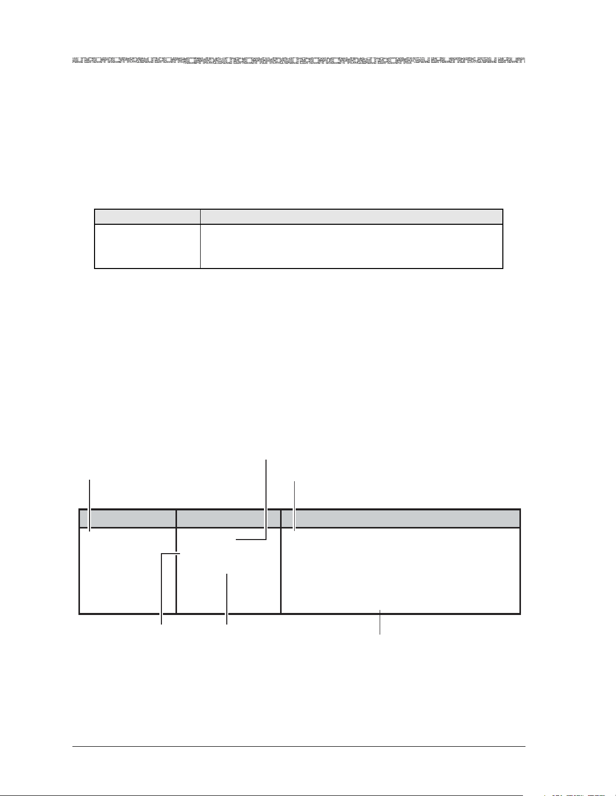
Table 1-2. Command Description Table Example
Command Function
Bring All Interfaces
Into Service
Brings the out-of-service configured interfaces to in-service status.
Note: In GR-303 configuration, it is critical to bring into service
Note: text convention (see Table 1-2).
only those channels actively configured with DS1 ports.
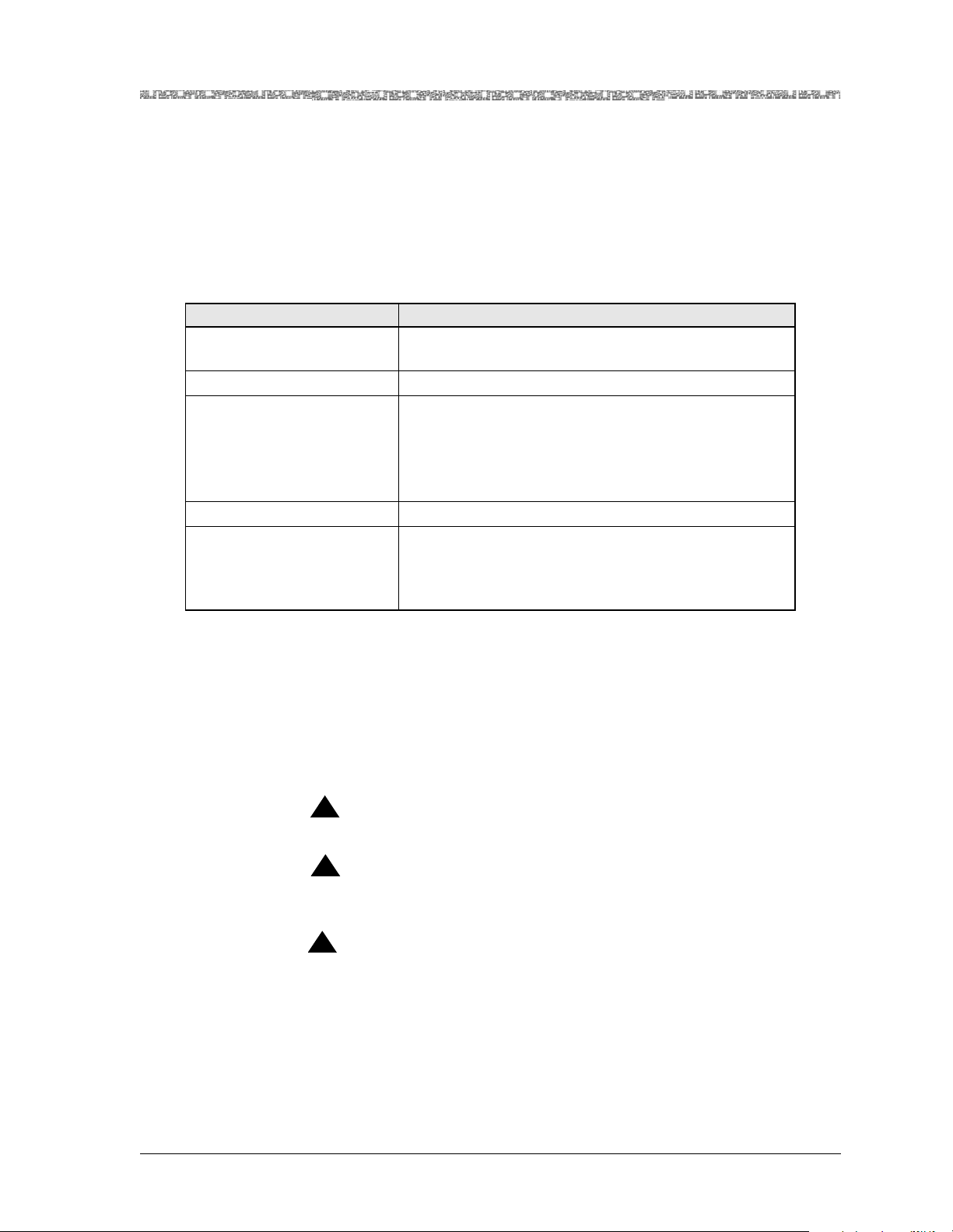
Use of Field Description Tables
For all illustrations for configuration windows in this guide for both the
PSAX system console interface and the EMS-PSAX, the field description
tables normally follow the command description tables. Field description
tables define the editable and the display-only fields, their functions, valid
values, and constraints, if applicable. As in the command description tables,
Note: text convention is also used, where appropriate, in the field descrip-
the
tion tables to alert the user to special instructions or configuration constraints
(see Figure 1-1).
Identifies editable fields
or display-only fields on
screens
Identifies initial field
value default
Describes the function of the field
and special instructions for
configuring modules
Field Name Field Values Description
Interface Type Default: 0
Range: 0-22
Format: Numeric
Specifies the type of end-to-end connection
protocol that governs the transmission parameters
for this configured port and channel interface.
Note: When certain types of interfaces are selected in this field, other configuration fields are displayed on this window.
Identifies available
range for field value
when applicable
Figure 1-1. Field Description Table Example
PacketStar® PSAX 3-Port DS3/E3 ATM Protection Module User Guide, Issue1 Release10.0.0
1-6 255-700-585
Identifies field value format as
Numeric, Predefined Alphanumeric,
Hexadecimal, or Valid Dotted Quad.
Decribes special instructions or
configuration constraints
Page 19

Chapter 1 Getting Started
General Navigational Guidelines
General Navigational Guidelines
Selecting Options, Fields, and Commands Using the Console Interface
Follow these guidelines to select an option, field, or command on the PSAX
console interface windows and to navigate through the windows:
• To select an option, field, or command, do one of the following:
~ Press the Up, Down, Left, or Right Arrow to highlight (reverse video
image) the option name, field name, or command you want to select and
press Enter as many times as necessary until the field choice you want is
displayed.
~ Use the alternate keys, K=UP, H=LEFT, L=RIGHT to highlight (reverse
video image) the option name, field name, or command you want to
select and press Enter. (You can optionally redefine these alternate keys
from the User Options window, which is accessible from the Console
Interface Main Menu window.)
~ To quickly select a command, you can also simultaneously press Ctrl and
the letter underlined in the command.
Once an option name, field, or command is selected, the system responds
as described in Table 1-3.
Table 1-3. System Responses to Selecting Options, Fields, or Commands
For a selected... the following occurs:
option name The window corresponding to the option name is displayed.
field The following variations occur:
• The field entry area is blank or contains the default or previously
entered value. Press Enter to enter or change data in this field. Press
Enter again to exit edit mode.
• The field entry area, like the field name, is displayed in reverse video
image and contains a predefined set of values, which you can view or
select by pressing Enter to navigate forward through these values. To
navigate backward through these field values, press Ctrl+H or the
Backspace key.
Read-only fields, which you cannot change, are enclosed in square brackets (example: [LineStatus]).
command The following variations occur:
• A message in the information line indicating an error or successful com-
pletion of the command is displayed.
• The next higher level or previous window (window name) is displayed.
• The next lower level or succeeding window (window name) is displayed.
• To navigate through the Console windows, use the shortcuts listed in
Table 1-4.
PacketStar® PSAX 3-Port DS3/E3 ATM Protection Module User Guide, Issue1 Release10.0.0
255-700-585 1-7
Page 20

Chapter 1 Getting Started
Help Information
Table 1-4. Shortcut Keys for Navigating Console Interface Windows
If you want to... press...
redisplay the previous window Ctrl+B on the window.
redisplay the Console Interface Main Menu window Ctrl+G on the window.
refresh the window Ctrl+R on the window.
On all the PSAX system windows, each command or menu option has an
underlined letter. The control key plus an underlined letter is a shortcut to
that command or menu option. You can use the navigation keys and hotkeys
with the Caps Lock key on or off. Always observe the status line at the bottom of the window for instructions and information.
Help Information
The Help windows are accessible from any window in the PSAX system console interface. To access the Help windows, press the ? (Question Mark) key
on any window. In addition to the Help windows, the Console Interface windows display contextual help in the information line at the bottom of each
window. Contextual help provides information about the command or field
currently highlighted on that window. The information line also displays
error codes and responses to commands. All responses and notifications are
recorded in a trap log. See the PacketStar
Protocol (SNMP) Trap Reference Guide for details on displaying the trap log and
obtaining explanations of the trap messages.
®
PSAX Simple Network Management
To view the Help windows from the Console Interface Main Menu window,
perform the following procedure.
Begin
1 On the window for which help is desired, press the ? (question mark)
key.
The Help window for the current console window is displayed (see
Figure 1-2).
PacketStar® PSAX 3-Port DS3/E3 ATM Protection Module User Guide, Issue1 Release10.0.0
1-8 255-700-585
Page 21
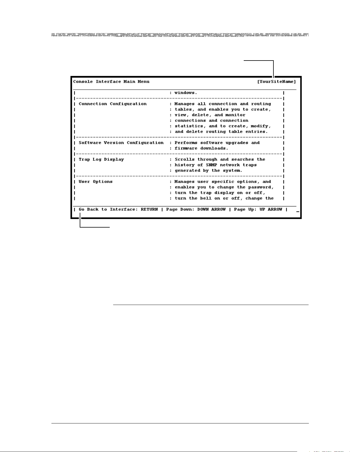
d
Your site name appears here
after initial configuration
Chapter 1 Getting Started
Technical Support
Information Line
Figure 1-2. Main Menu Help Window
2 To display the remaining Help windows for the current console window,
3 To scroll backward through the Help windows for the current console
4 To exit Help and return to the current console window, press the Enter
En
Technical Support
If you experience a problem with the 3-Port DS3/E3 ATM Protection module,
refer to the Lucent Technologies Product Warranty Registration Information, which
accompanied your shipment, for instructions on obtaining support in your
area.
press the Down Arrow key.
window, press the Up Arrow key.
key.
PacketStar® PSAX 3-Port DS3/E3 ATM Protection Module User Guide, Issue1 Release10.0.0
255-700-585 1-9
Page 22

Chapter 1 Getting Started
Before You Begin
Before You Begin
Before you start configuring and using your new 3-Port DS3/E3 ATM Protection module, be sure you:
• Record your site-specific specifications such as the IP addresses you will
use, and the connections and interfaces you will need. Decide which user
names and passwords you will assign.
• Make sure you have IP connectivity to all PSAX devices to be managed
• Determine the numbering scheme for any in-band management connec-
tions you will be using
Comments on This Guide
To comment on the PacketStar® PSAX 3-Port DS3/E3 ATM Protection Module User
Guide, please complete the comment card at the following web address:
http://www.lucent-info.com/comments/
You can also email your comments to comments@lucent.com.
Include the following information:
Title: PacketStar
Release number: Release 10.0.0
Document number: 255-700-585
Issue number: Issue 1
Publication date: December 2004
®
PSAX 3-Port DS3/E3 ATM Protection Module User Guide
PacketStar® PSAX 3-Port DS3/E3 ATM Protection Module User Guide, Issue1 Release10.0.0
1-10 255-700-585
Page 23
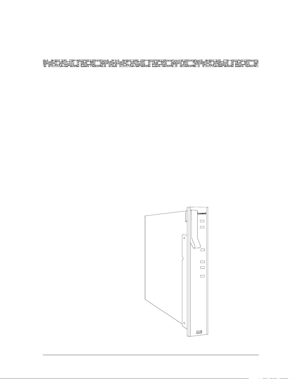
Overview of the Module
The 3-Port DS3/E3 ATM Protection module (see Figure 2-1) provides 1:1
traffic protection for ATM services when connected to a LIM3–1 module in
the PSAX 1000 chassis and N:1 traffic protection for ATM services when connected to a LIM3–4 module in the PSAX 4500 chassis. In addition to its traffic
protection capabilities, this module provides the same functionality as the
3-Port DS3/E3 ATM module (model 23N74): ATM service, including ATM
UNI 3.0, 3.1, and 4.0; ATM IISP user and network; and ATM PNNI 1.0 interfaces. It is software configurable to function in either the DS3 or the E3
mode, enabling you to deliver DS3 or E3 configurations while maintaining
inventory of a single module type. The three high-speed ATM network interfaces operate at DS3, with a line rate of 44.736 Mbps, or at E3, with a line
rate of 34.368 Mbps. Each port can be configured for ATM service, including
ATM UNI 3.0, 3.1, and 4.0; ATM IISP user and network; and ATM PNNI 1.0
interfaces.
l
The 3-Port DS3/E3 ATM Protection module has four types of LED indicators:
FAIL, ACTIVE, STBY, and LOS (loss of signal). See Figure 2-1 for an illustration of this module.
2 Module Description
FAIL
ACTIVE
DS3/E3
ATM
STBY
LOS 1
LOS 2
LOS 3
Figure 2-1. 3-Port DS3/E3 ATM Protection Module
PacketStar® PSAX 3-Port DS3/E3 ATM Protection Module User Guide, Issue1 Release10.0.0
255-700-585 2-1
Page 24

Chapter 2 Module Description
Protection Features
Protection Features
The 3-Port DS3/E3 ATM Protection module provides 1:1 protection on the
PSAX 1000 and N:1 protection on the PSAX 4500.
1:1 Protection Feature
The following sections describe how all aspects of the 1:1 Protection feature
work.
1:1 Traffic Protection Modules
The 1-to-1 (1:1) Protection feature on the PSAX 1000 Multiservice Media
Gateway system provides traffic protection by configuring the system to use
the 1:1 Traffic Protection modules. These modules do not have external connectors, but receive traffic from and transmit traffic to the network by physical connection at the PSAX 1000 chassis midplane to corresponding 3-Port
Line Interface modules (LIM3–1 modules). The 1:1 Traffic Protection modules are installed at the front of the chassis. The LIM3–1 modules, which are
installed at the rear of the chassis, receive incoming traffic and transmit outgoing traffic via the attached network cables on the external connectors on
the faceplates. The LIM3–1 modules are electrically connected to the protection module for a protection group via the midplane.
Protection Group
Working Module Monitoring
The 1:1 Protection feature supports the configuration of one protection group
for the PSAX 1000 system that contains one working module and one protection module of the same type, and one LIM3–1 module for the working
module. The working module is installed in slot
is installed in slot
ing module.
In the 1:1 scheme, one working module in a protection group is associated
with one protection module. Under normal conditions, the working module
in a protection group is in Active mode, exchanging traffic, and the protection module is in Standby mode.
The 1:1 Traffic Protection modules can also be used in a nonprotected configuration in which one of these modules can be installed in slot
sponding LIM3–1 module installed directly behind it.
Traffic is switched from a working module to its associated protection module
under the following conditions:
• Working module failure
• Removal of the working module from the chassis
• Manual switchover initiated by the user
• Nonservice affecting upgrades
15. A LIM3–1 module is installed directly behind the work-
4 and the protection module
4 with a corre-
The protection module monitors the operation of the working module. InterSlot Communication (ISC) cells are exchanged between the working and
protection module. If the protection module detects eight consecutive miss-
PacketStar® PSAX 3-Port DS3/E3 ATM Protection Module User Guide, Issue1 Release10.0.0
2-2 255-700-585
Page 25

Switchover Events
Chapter 2 Module Description
Protection Features
ing ISC cells from a working module, the protection module sends a message
to the CPU indicating the working module failure. A likely cause of this condition is that processing on the working module is interrupted or suspended.
Other causes of this condition are the removal of the working module from
the chassis or a failure of the module.
During the switchover of traffic from the working module to the protection
module, various events occur depending on the reason why the switchover
was initiated. These events are described in the following scenarios:
Working module failure or removal
•
After the protection module detects the failure or removal of the working
module, automatic switchover occurs. The protection module notifies the
CPUn module that the working module has failed or been removed.
The protection module was configured at the time the working module
was originally configured. The protection module instructs the LIM3–1
module to transfer traffic from the working module to the protection module, which is now placed into Active mode. No need exists for the CPUn
module to download configuration information from the working module.
The CPUn module then brings the connections into service on the protection module. In this scenario, the connection downtime is only the amount
of time needed for electrical switching on the LIM3–1 module.
Manual switchover initiated by the user
•
The user can manually switch traffic from the working module to the protection module. This action might be taken in preparation for removing the
working module from the chassis for maintenance purposes or testing the
working module for diagnostic purposes. When the user executes the
switchover command, the CPUn module downloads the working module
and connection configurations to the protection module, and then instructs
the LIM3–1 module to transfer traffic from the working module to the protection module. In this scenario, the connection downtime is only the
amount of time needed for electrical switching on the LIM3–1 module.
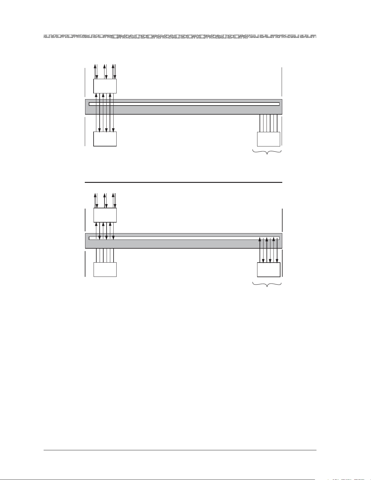
Figure 2-2 illustrates the data flow in a 1:1 scheme during normal operation,
and the data flow while the protection module is in Active mode following
the failure of the working module.
PacketStar® PSAX 3-Port DS3/E3 ATM Protection Module User Guide, Issue1 Release10.0.0
255-700-585 2-3
Page 26
Chapter 2 Module Description
Protection Features
1 2 3
Midplane
Midplane
LIM3-1
Slot 4
Working
Module
Slot 4
1 2 3
LIM3-1
Slot 4
Normal Data Flow
Protection
Module
Slot 15
Standby
Rear
Panel
Midplane
Front
Panel
Rear
Panel
Midplane
Working
Module
Slot 4
Failed Working Module
Figure 2-2. 1:1 Protection Scheme on the PSAX 1000 System
Restoration of Service on the Working Module
After automatic or manual switchover has been performed and the replacement or testing of the working module is completed, the user manually
switches the traffic back from the protection module to the working module,
which resumes Active mode. The following events occur depending on
whether the working module is an existing one having all configurations
loaded, or is a new module that replaces a failed working module.
• Existing working module
Protection
Module
Slot 15
ACTIVEFAILED
Front
Panel
PacketStar® PSAX 3-Port DS3/E3 ATM Protection Module User Guide, Issue1 Release10.0.0
2-4 255-700-585
Page 27

When the user executes the switchover command, the PSAX system
instructs the LIMnn module to switch the traffic from the protection module running in Active mode to the working module. The working module
is then placed into Active mode and the protection module is placed into
Standby mode.
• Replacement working module
When the user inserts the new replacement module into the chassis, the
PSAX system recognizes it as an unconfigured module. The user then executes the switchover command, and the PSAX system downloads the module and connection configurations from the protection module to the new
working module. After this download is finished, the system instructs the
LIMnn module to switch the traffic from the protection module running in
Active mode to the working module. The working module is then placed
into Active mode and the protection module is placed into Standby mode.
The connection downtime during this manual switchover in the previous
scenarios is only the amount of time needed to switch the LIMnn module.
N:1 Protection Feature
Chapter 2 Module Description
Protection Features
N:1 Traffic Protection Modules
Protection Groups
The following sections describe how all aspects of the N:1 Protection feature
work.
The N-to-1 (N:1) Protection feature on the PSAX 4500 Multiservice Media
Gateway system provides traffic protection by configuring the system to use
the N:1 Traffic Protection modules. These modules do not have external connectors, but receive traffic from and transmit traffic to the network by physical connection at the PSAX 4500 chassis midplane to corresponding 3-Port
Line Interface modules (LIM3–4 modules). The N:1 Traffic Protection modules are installed at the front of the chassis. The LIM3–4 modules, which are
installed at the rear of the chassis, receive incoming traffic and transmit outgoing traffic via the attached network cables on the external connectors on
the faceplates. The LIM3–4 modules are electrically connected to the protection module for a protection group via the midplane.
The N:1 Protection feature supports the configuration of one or two protection groups for the PSAX 4500 system, with each group containing either
one-to-six or one-to-four working modules of the same type, one LIM3–4
module for each working module, and one protection module of the same
type for each group. The protection groups are set up as follows.
• For group 1, up to six working modules are installed in slots
8, and the protection module is installed in slot 15. A LIM3–4 module
and
3, 4, 5, 6, 7,
is installed directly behind each working module.
• For group 2, up to four working modules are installed in slots
12, and the protection module is installed in slot 13. A LIM3–4 module is
9, 10, 11, and
installed directly behind each working module.
Two types of protection schemes are supported for each protection group: N:1
and 1:1. In the N:1 scheme, one to six working modules are associated with
one protection module in group 1, and one to four working modules are
PacketStar® PSAX 3-Port DS3/E3 ATM Protection Module User Guide, Issue1 Release10.0.0
255-700-585 2-5
Page 28

Chapter 2 Module Description
Protection Features
associated with one protection module in group 2. In the 1:1 scheme, only
one working module in a protection group is associated with one protection
module. Under normal conditions, the working module in a protection group
is in active mode, exchanging traffic, and the protection module is in standby
mode.
The N:1 Traffic Protection modules can also be used in a nonprotected configuration in which these modules can be installed in slots
each Protection module has a corresponding LIM3–4 module installed
directly behind the Protection module that the LIM3–4 module is serving. If
any slots in the range of slots designated for group 1 (slots
9–12) are not configured for a protection group, the unused slots can be
(slots
used for other types of PSAX I/O or server modules.
Working Module Monitoring
Traffic is switched from a working module to its associated protection module
under the following conditions:
• Working module failure
• Removal of the working module from the chassis
• Manual switchover initiated by the user
• Nonservice affecting upgrades
3–12 only as long as
3–8) and group 2
Switchover Events
The protection module monitors the operation of the working module. InterSlot Communication (ISC) cells are exchanged between the working and
protection module. If the protection module detects eight consecutive missing ISC cells from a working module, the protection module sends a message
to the CPU indicating the working module failure. A likely cause of this condition is that processing on the working module is interrupted or suspended.
Other causes of this condition are the removal of the working module from
the chassis or a failure of the module.
During the switchover of traffic from the working module to the protection
module, various events occur depending on the reason why the switchover
was initiated. These events are described in the following scenarios:
Working module failure or removal
•
After the protection module detects the failure or removal of the working
module, automatic switchover occurs. The protection module notifies the
CPUn module that the working module has failed or been removed. After
this notification, the following sequence of events occurs depending on
which type of protection scheme is being used:
In the 1:1 scheme, the protection module was configured at the time the
~
working module was originally configured. The protection module
instructs the LIM3–4 module to transfer traffic from the working module
to the protection module, which is now placed into Active mode. No
need exists for the CPUn module to download configuration information
from the working module. The CPUn module then brings the connections into service on the protection module. In this scenario, the connection downtime is only the amount of time needed for electrical switching
on the LIM3–4 module.
PacketStar® PSAX 3-Port DS3/E3 ATM Protection Module User Guide, Issue1 Release10.0.0
2-6 255-700-585
Page 29

Chapter 2 Module Description
Protection Features
~ In the N:1 scheme, the protection module instructs the LIM3–4 module
to transfer traffic from the working module to the protection module,
which is now placed into Active mode. The CPUn module then downloads the module and connection configurations from the working module to the protection module, and restores traffic flow. In this scenario,
connection downtime is slightly longer than that for the 1:1 scheme
because the module and connection configurations must be downloaded
to the protection module.
Manual switchover initiated by the user
•
The user can manually switch traffic from the working module to the protection module. This action might be taken in preparation for removing the
working module from the chassis for maintenance purposes or testing the
working module for diagnostic purposes. When the user executes the
switchover command, the CPUn module downloads the working module
and connection configurations to the protection module, and then instructs
the LIM3–4 module to transfer traffic from the working module to the protection module. In this scenario, the connection downtime is only the
amount of time needed for electrical switching on the LIM3–4 module.
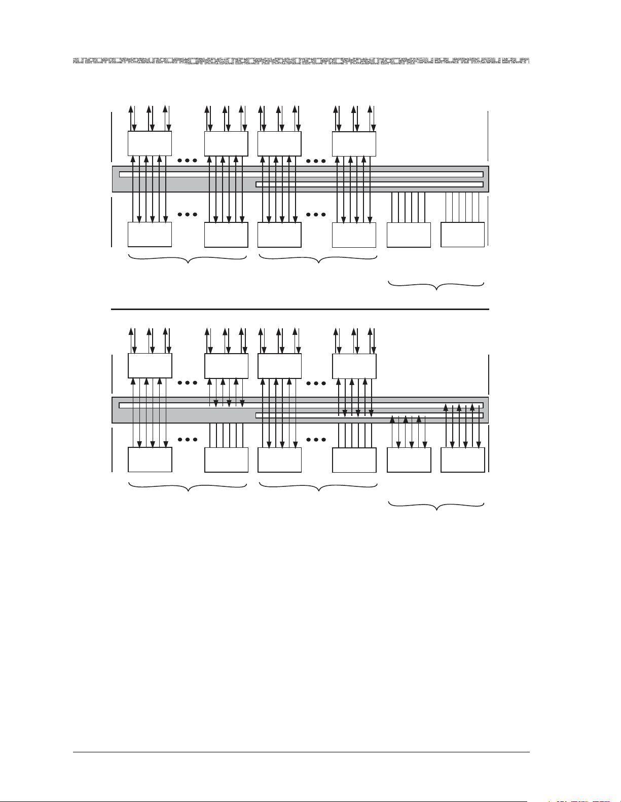
Figure 2-2 illustrates the data flow in an N:1 scheme during normal operation, and the data flow while the protection modules are in Active mode following the failure of a working module in groups 1 and 2.
PacketStar® PSAX 3-Port DS3/E3 ATM Protection Module User Guide, Issue1 Release10.0.0
255-700-585 2-7
Page 30
Chapter 2 Module Description
Protection Features
1 2 3
1 2 3 1 2 3
1 2 3
Midplane
Midplane
LIM3-4
Slot 3
Working
Module
Slot 3
1 2 3
LIM3-4
Slot 3
Group 1
LIM3-4
Slot 8
Working
Module
Slot 8
LIM3-4
Slot 9
Working
Module
Slot 9
Normal Data Flow
1 2 3 1 2 3 1 2 3
LIM3-4
Slot 8
LIM3-4
Slot 9
Group 2
LIM3-4
Slot 12
Working
Module
Slot 12
LIM3-4
Slot 12
Protection
Module
Slot 13
Protection
Module
for Group 2
Standby
Protection
Module
Slot 15
Protection
Module
for Group 1
Rear
Panel
Midplane
Front
Panel
Rear
Panel
Midplane
Working
Module
Slot 3
Slot 8
FAILED FAILED
Group 1
Working
Module
Slot 9
Group 2
Failed Working Modules
Figure 2-3. N:1 Protection Scheme on the PSAX 4500 System
Restoration of Service on the Working Module
After automatic or manual switchover has been performed and the replacement or testing of the working module is completed, the user manually
switches the traffic back from the protection module to the working module,
which resumes Active mode. The following events occur depending on
whether the working module is an existing one having all configurations
loaded, or is a new module that replaces a failed working module.
• Existing working module
Slot 12
Protection
Module
Slot 13
Protection
Module
for Group 2
ACTIVE
Protection
Module
Slot 15
Protection
Module
for Group 1
Front
Panel
PacketStar® PSAX 3-Port DS3/E3 ATM Protection Module User Guide, Issue1 Release10.0.0
2-8 255-700-585
Page 31

When the user executes the switchover command, the PSAX system
instructs the LIMnn module to switch the traffic from the protection module running in Active mode to the working module. The working module
is then placed into Active mode and the protection module is placed into
Standby mode.
• Replacement working module
When the user inserts the new replacement module into the chassis, the
PSAX system recognizes it as an unconfigured module. The user then executes the switchover command, and the PSAX system downloads the module and connection configurations from the protection module to the new
working module. After this download is finished, the system instructs the
LIMnn module to switch the traffic from the protection module running in
Active mode to the working module. The working module is then placed
into Active mode and the protection module is placed into Standby mode.
The connection downtime during this manual switchover in the previous
scenarios is only the amount of time needed to switch the LIMnn module.
Software Features
Chapter 2 Module Description
Software Features
The 3-Port DS3/E3 ATM Protection module implements ATM Forum specifications UNI 3.0, 3.1,and 4.0, and PNNI 1.0, which allow the DS3 or E3 ports
to function as a user-network interface (UNI), an IISP user or IISP network
interface, or as a PNNI network interface to an ATM network. This module
also supports the virtual interface traffic shaping protocol.
Hardware Features
The 3-Port DS3/E3 ATM Protection module has the following hardware
features:
• Number of ports: 3
• Connector type: No external connectors; 6 BNC connectors, 1 receive con-
nector and 1 transmit connector for each port, are located on the LIM3–1
module on the rear of the PSAX 1000 chassis or the LIM3–4 module on the
rear of the PSAX 4500 chassis
• Line rate:
~ DS3: 44.736 Mbps
~ E3: 34.368 Mbps
• Line encoding mode:
~ DS3: B3ZS
~ E3: HDB3
• Line buildout: DS3 only
~ Short [0–40.5 m (0–133 ft)]
~ Long [0–81.1 m (0–266 ft)]
• Framing modes:
~ DS3: C-bit parity, clear channel, M23
PacketStar® PSAX 3-Port DS3/E3 ATM Protection Module User Guide, Issue1 Release10.0.0
255-700-585 2-9
Page 32

Chapter 2 Module Description
Hardware Specifications
~ E3: G751, G832
• Loopback capabilities: local loopback, line loopback, payload loopback
• Cell mapping:
~ DS3: PLCP, direct mapping
~ E3: direct mapping
Hardware Specifications
Table 2-1 provides the general physical hardware and environmental specifications for the PSAX I/O module.
Table 2-1. Physical Hardware Specifications for the PSAX I/O Module
Specification Description
Dimensions 17.3 cm H x 2.41 cm W x 24.1 cm D
Weight 0.45 kg (1.0 lb.), approximate
Operating temperature range for all the
PSAX 1250, PSAX 2300, and
PSAX 4500 systems
Operating temperature range for the
PSAX 1000 systems
(6.8 in. H x 0.95 in. W x 9.5 in. D)
0° to 50° C (32° to 122° F)
For AC-powered PSAX 1000 systems:
0° to 50° C (32° to 122° F)
For DC-powered PSAX 1000 systems:
-20° to 60° C (-4° to 140° F) with a cold start minimum of
0° C (32° F)
Operating humidity range for all chassis 5% to 85% relative humidity
Operating altitude range for all chassis 60 meters (197 feet) below sea level to 4,000 meters
(13,123 feet) above sea level
Storage temperature range for all
chassis
Storage humidity range for all chassis 0% to 90% noncondensing
-40° to 70° C (-40° to 158° F)
Performance and Power Specifications
Table 2-2 provides the chassis speed, power consumption, and memory allocation specifications for this module.
PacketStar® PSAX 3-Port DS3/E3 ATM Protection Module User Guide, Issue1 Release10.0.0
2-10 255-700-585
Page 33

Chapter 2 Module Description
Module Placement
Table 2-2. Performance and Power Specifications for the 3-Port DS3/E3 ATM Protection Module
To ta l
Module
45N74 3-Port
Amount of
SDRAM
72MB 8MB 32MB 32MB
DS3/E3 ATM
Protection
*
The I/O buffers carry 16,384 cells per megabyte.
†
Indicates the size of the output buffer followed by the maximum number of 64-byte cells in the output
buffer.
Module
Program and
Data Space
Maximum
Input
*
Buffer
Output
†
Buffer
(524,288)
Chassis
Speed
High
Speed
Module Placement
The 3-Port DS3/E3 ATM Protection module can be installed in either the
PSAX 1000 chassis or the PSAX 4500 chassis. In the PSAX 1000 chassis, this
module is installed in slot
tion module. The working module must be physically connected at the chassis midplane to a LIM3–1 module at a corresponding slot in the rear of the
chassis. See the PSAX 1000 3-Port Line Interface Module Description and Specifica-
tions document for LIM3–1 module installation instructions.
The 3-Port DS3/E3 ATM Protection module is installed in either of two
groups in the PSAX 4500 chassis: group 1, in slots
and slot
module and slot
15 as a protection module; or group 2, in slots 9–12 as a working
13 as a protection module. Each group must contain a mini-
mum of one working module and one protection module. Each working
module must be physically connected at the chassis midplane to a LIM3–4
module at a corresponding slot in the rear of the chassis. The 1:1 Protection
feature of this module functions only in this configuration. See the
PSAX 4500 3-Port Line Interface Module Description and Specifications document
for LIM3–4 module installation instructions.
4 as a working module and in slot 15 as a protec-
3–8 as a working module
Maximum
Power
Consumption
12 W
LED Status Indicators
Table 2-3 describes how the light-emitting diode (LED) indicators on the
3-Port DS3/E3 ATM Protection module faceplate respond to different module
conditions. These LEDs indicate if the module has been installed properly.
PacketStar® PSAX 3-Port DS3/E3 ATM Protection Module User Guide, Issue1 Release10.0.0
255-700-585 2-11
Page 34

Chapter 2 Module Description
Loopback Configuration Options
Table 2-3. LED Indicators for the 3-Port DS3/E3 ATM Protection Module
Module
Status
LED
FAIL
(red)
ACTIVE
(green)
STBY
(green)
LOS 1
(yellow)
LOS 2
(yellow)
LOS 3
(yellow)
*
†
One or
More
Configured
Ports
when the
No Cable on
Port
Cable on
N/A N/A
Port
Initial
Power-On
Lights
briefly
No
Configured
Ports
Not lit Lights only
*
module is
not functioning
Lights
briefly
Not lit Lights only
*
N/A N/A
when the
module is
actively
exchanging traffic
Lights
briefly
Not lit Lights only
*
when the-
N/A N/A
module is
passive and
on standby
Lights
briefly
N/A N/A Lights • Does not
†
light if signal is being
received
• Lights if
signal is
missing
After power is initially applied to the system and the system boot is complete,
the FAIL LED indicates whether the module hardware has failed (red), the
ACTIVE LED indicates whether the module has one or more ports configured
(green), and the STBY LED indicates whether the module is in STANDBY
mode (yellow).
After power is initially applied to the system and the system boot is complete,
this loss of signal LED indicates whether the port has a cable connected to its
corresponding LIM3–4 module. This description applies only to modules in
ACTIVE mode.
Loopback Configuration Options
To aid network troubleshooting and testing, loopback capability is provided
for the 3-Port DS3/E3 ATM Protection module.
The loopback option on the module port and channel configuration window
for the module enables you to verify the integrity of a port by transmitting a
received signal back to the source. Selecting a loopback option is described in
the module configuration procedure.
Figure 2-4 illustrates the line loop, payload loop, and local loop options.
PacketStar® PSAX 3-Port DS3/E3 ATM Protection Module User Guide, Issue1 Release10.0.0
2-12 255-700-585
Page 35

Chapter 2 Module Description
Loopback Configuration Options
Por t
Connector
Line Loop
Line Driver
Signal
Receiver
Port Connector
Backplane
Connector
Payload Loop
Local Loop
Line Driver
Receiver
Backplane
Connector
Figure 2-4. Loopback Configuration Options on the Module
Framing Chip
Backplane
Connector
PacketStar® PSAX 3-Port DS3/E3 ATM Protection Module User Guide, Issue1 Release10.0.0
255-700-585 2-13
Page 36

Chapter 2 Module Description
Loopback Configuration Options
PacketStar® PSAX 3-Port DS3/E3 ATM Protection Module User Guide, Issue1 Release10.0.0
2-14 255-700-585
Page 37

3 Configuring Ports and Channels
Overview of This Chapter
This chapter describes how to use the console interface to perform the following tasks on the 3-Port DS3/E3 ATM Protection module:
• “Obtaining General Module Data and Accessing Ports and Channels”
• “Configuring the Ports in DS3 Mode”
• “Configuring the Ports in E3 Mode”
• “Viewing Port Statistics”
• “Configuring N:1 Protection Groups”
• “Viewing and Changing N:1 Protection Groups”
• “Saving the Module Configuration”
Before You Begin
Be sure to complete the following tasks first before configuring the 3-Port
DS3/E3 ATM Protection module:
• Configure your basic system (see “Configuring the System for Your Site” in
the PacketStar
• Configure the Stratum 3–4 module (see “Configuring the Stratum 3–4
Module” in the PacketStar
®
PSAX Multiservice Media Gateway User Guide).
Using the Console
®
PSAX Multiservice Media Gateway User Guide).
When configuring the 3-Port DS3/E3 ATM Protection module using the console interface, display-only fields are displayed in square brackets ([ ]).
Obtaining General Module Data and Accessing Ports and Channels
This section describes how to obtain product, model, version, and serial number data about a module from the Equipment Configuration window. In
addition, the window provides operational status and alarm conditions on
each installed module. You also use this window to access the port and channel configuration windows for the PSAX modules.
Accessing the Equipment Configuration Window
Perform the following procedure to access the Equipment Configuration window.
PacketStar® PSAX 3-Port DS3/E3 ATM Protection Module User Guide, Issue1 Release10.0.0
255-700-585 3-1
Page 38

Chapter 3 Configuring Ports and Channels Using the Console
Obtaining General Module Data and Accessing Ports and Channels
Begin
1 On the Console Interface Main Menu window, select the Equipment
Configuration option.
The Equipment Configuration window is displayed (see Figure 3-1
through Figure 3-5).
2 View the operational and alarm status, software version, PEC, and serial
number data of the installed modules.
3 When you are ready to begin configuring the ports and channels of the
module, select the line displaying the name of the module you want to
configure.
4 Proceed to the section, “Configuring the Ports,” for module configuration
procedures.
Note: The sample Equipment Configuration windows in the following
figures may not show the actual module you are configuring.
These figures illustrate the variations of slot configurations for
the different PSAX chassis displayed on the Equipment Configuration window.
End
Figure 3-1. Sample Equipment Configuration Window on a PSAX 1000
System (Page 1)
PacketStar® PSAX 3-Port DS3/E3 ATM Protection Module User Guide, Issue1 Release10.0.0
3-2 255-700-585
Page 39

Chapter 3 Configuring Ports and Channels Using the Console
Obtaining General Module Data and Accessing Ports and Channels
Figure 3-2. Sample Equipment Configuration Window on a PSAX 1250
System (Page 1)
Figure 3-3. Sample Equipment Configuration Window on a PSAX 2300 or
PSAX 4500 System (Page 1)
PacketStar® PSAX 3-Port DS3/E3 ATM Protection Module User Guide, Issue1 Release10.0.0
255-700-585 3-3
Page 40

Chapter 3 Configuring Ports and Channels Using the Console
Obtaining General Module Data and Accessing Ports and Channels
Figure 3-4. Sample Equipment Configuration Window on a PSAX 1000,
PSAX 2300, or PSAX 4500 System (Page 2)
Figure 3-5. Sample Equipment Configuration Window on a PSAX 1250
System (Page 2)
Commands The commands in this window have the following functions.
PacketStar® PSAX 3-Port DS3/E3 ATM Protection Module User Guide, Issue1 Release10.0.0
3-4 255-700-585
Page 41

Chapter 3 Configuring Ports and Channels Using the Console
Obtaining General Module Data and Accessing Ports and Channels
Command Function
Update Display Refreshes the current status of the modules in the PSAX chassis.
Page Down Displays the second page of the Equipment Configuration win-
dow. This command toggles with Page Up.
Page Up Displays the first page of the Equipment Configuration window.
This command toggles with Page Down.
Interface by Name Displays the Interface Name Table window on which you can
view all the interface names in the PSAX system.
Go Back to Main Menu Redisplays the Console Interface Main Menu window.
Field Description The display-only fields on this window are described in Table 3-1.
Table 3-1. Equipment Configuration Window Field Descriptions
Field Name Field Value Description
Slot Default: N/A
Displays the slot number in the PSAX chassis.
Range: 1–25, depends
on chassis type
Format: Numeric
Module Type Default: N/A
Range: N/A
Format: Predefined
Displays the type of the module in the slot. When a
module is inserted into the chassis, its name is displayed in the Module Type field next to the slot number. When the module is removed from the chassis, its
name is no longer displayed in the Module Type field
and is replaced with None.
Status Default: Unknown
Displays the operational status of the module.
Range: N/A
Format: Predefined
Unknown Indicates that the module has not been configured.
Primary Indicates one of the following:
• at least one port or channel on an I/O module has
been configured.
• a CPU module is functioning as the primary CPU
module.
Standby Indicates one of the following:
• a module in redundant systems is operating as the
standby (backup) module to the primary (active)
module.
• a CPU module in redundant systems is functioning
as the standby (backup) CPU module.
Alarm Status Default: No Alarm
Range: N/A
Format: Predefined
Displays the present alarm condition of the module.
For the alarm status conditions, see the table “Alarm
Status Descriptions for Modules” following this table.
PacketStar® PSAX 3-Port DS3/E3 ATM Protection Module User Guide, Issue1 Release10.0.0
255-700-585 3-5
Page 42

Chapter 3 Configuring Ports and Channels Using the Console
Obtaining General Module Data and Accessing Ports and Channels
Table 3-1. Equipment Configuration Window Field Descriptions (Continued)
Field Name Field Value Description
SW # Default: N/A
Range: N/A
Format: Predefined
Displays the version of PSAX system software with
which the modules’ firmware was released. The software version is encoded in the module firmware.
Because not all modules require firmware upgrades
with every new PSAX system software release, the
software version that is displayed in this window may
be lower than the CPU system software that is currently running on the PSAX system. See the most
recent Release Note document for the latest software
and firmware lineup information.
PEC Default: N/A
Range: N/A
Format: Predefined
Serial # Default: N/A
Range: N/A
Format: Predefined
Displays the product element code (PEC) used to identify and order this type of module. The PEC is encoded
in the module bootloader.
Displays the unique serial number of the individual
module. The product serial number is encoded in the
module firmware. The format of this field is the following:
PSAX System Rel. 6.5.0 and later: 12-digit number in
the format: YYVVDDnnnnnn, where YY = year of manufacture VV = vendor ID code (manufacturer and location) DD = date code of manufacture (either month or
week depending on vendor’s preference) nnnnnn =
sequential number, which in conjunction with YY, VV,
and DD, creates a unique number for each hardware
component in the PSAX product line
For existing products with the 10-digit serial number
used in Rel. 6.5.0 or later systems, this number is displayed with two preceding zeros.
PSAX Rel. 6.3.0 and earlier: 10-digit number. For
products with 12-digit serial numbers used in Rel 6.3.0
or earlier systems, the first two digits (YY) are not displayed.
Alarm Status Values
The Alarm Status field on the Equipment Configuration window is described
in Table 3-2.
PacketStar® PSAX 3-Port DS3/E3 ATM Protection Module User Guide, Issue1 Release10.0.0
3-6 255-700-585
Page 43

Chapter 3 Configuring Ports and Channels Using the Console
Table 3-2. Module Alarm Status Descriptions on the Equipment Configuration Window
Configuring the Ports
Alarm Status
Module Type
Affected
Description
NoAlarm I/O and Server Indicates that no alarms have been detected for the module
in this slot.
WrongCardType I/O and Server Indicates that one type of module was configured in this
slot in the chassis, but a now different module occupies this
slot.
LineFailed All Indicates that the module in this slot is no longer receiving
or transmitting signals because the line failed.
Hexadecimal format,
Example:
12345678ABC
I/O and Server Indicates that one or more ports on the module in this slot
currently have a loss of signal. The numbers indicate which
ports have a loss of signal. For modules that have more
than eight ports not receiving signals, the value in this field
is in hexadecimal format.
CardRemoved All Indicates that one of the following events occurred:
• The module in this slot was configured and then
removed from the slot.
• Connections on the OC-3, OC-12, STM-1, or STM-4
APS/MSP primary module in this slot were transferred to
the standby module. After the transfer occurs, the former
primary module then displays CardRemoved in the
Alarm Status field; the former standby module then displays Primary in the Status field.
ReferenceClockFailed Stratum 3–4 Indicates that the timing reference clock on the Stratum
module in this slot failed.
CompositeClockFailed Stratum 3–4 Indicates that the timing composite clock on the Stratum
module in this slot failed.
Overload Power Supply Indicates that the Power Supply module is operating under
an overload condition.
PowerFailed Power Supply Indicates that the power has failed.
Minus48vFailed Power Supply Indicates that the -48 V dc Power Supply module output
failed.
UnknownAlarm I/O and Server Indicates that the reason for failure is not known.
CompleteClockFailed Stratum 3–4 Indicates that the backplane detected a clock error.
PowerFailed Power Supply Indicates that no power is coming into the PSAX chassis.
Configuring the Ports
You must first configure the 3-Port DS3/E3 ATM Protection module before
you can set up connection provisioning. You can configure the module to
run in DS3 mode (see the next section, “Configuring the Ports in DS3
Mode”) or E3 mode (see the section ”Configuring the Ports in E3 Mode” on
page 3-20).
PacketStar® PSAX 3-Port DS3/E3 ATM Protection Module User Guide, Issue1 Release10.0.0
255-700-585 3-7
Page 44

Chapter 3 Configuring Ports and Channels Using the Console
Configuring the Ports
Configuring the Ports in DS3 Mode
To configure the module in DS3 mode, perform the following procedure.
Configuring the Ports (DS3 Mode)
Begin
1 On the Console Interface Main Menu window (see Figure 3-6), select the
Equipment Configuration option.
Figure 3-6. Console Interface Main Menu (Equipment Configuration Selected)
The Equipment Configuration window (see Figure 3-7) is displayed.
PacketStar® PSAX 3-Port DS3/E3 ATM Protection Module User Guide, Issue1 Release10.0.0
3-8 255-700-585
Page 45

Chapter 3 Configuring Ports and Channels Using the Console
Configuring the Ports
Figure 3-7. Equipment Configuration Window (As Displayed on the PSAX 1250,
PSAX 2300, and PSAX 4500 Console)
2 On the Equipment Configuration window, select a DS3E3-ATM-3P-
module in the list.
Note: The descriptions of the module alarm status values in the Alarm
Status field are provided in the reference appendix.
PacketStar® PSAX 3-Port DS3/E3 ATM Protection Module User Guide, Issue1 Release10.0.0
255-700-585 3-9
Page 46

Chapter 3 Configuring Ports and Channels Using the Console
Configuring the Ports
The Protection 3-Port DS3 ATM Configuration window (see Figure 3-8)
is displayed.
Figure 3-8. Protection 3-Port DS3 ATM Configuration Window
Commands The commands in this window have the following functions:
Command Function
Apply Operating Mode
Change
Changes the signaling mode in which the module will
operate. After selecting the value DS3 in the Operating
Mode field, select this command to apply the change. The
module reboots and the window reflects your selection.
Note: All interfaces must be unconfigured, out of service,
and deleted before using this command.
Update Display Updates the values in the fields to show the most current
configuration. Use this command to display the most current information in the Line Status field.
Delete All Interfaces Deletes the configured interfaces for the three ports. You
must take all interfaces out of service (using the Tak e A l l
Interfaces Out Of Service command) before you can use
this command to delete all the configured interfaces.
Bring All Interfaces Into
Service
Take All Interfaces Out Of
Service
Brings the out-of-service configured interfaces for the three
ports to in-service status.
Takes the in-service configured interfaces for the three
ports to out-of-service status. You must use this command
first before using the Delete All Interfaces command.
Go Back to Equipment
Redisplays the Equipment Configuration window.
Configuration
PacketStar® PSAX 3-Port DS3/E3 ATM Protection Module User Guide, Issue1 Release10.0.0
3-10 255-700-585
Page 47

Chapter 3 Configuring Ports and Channels Using the Console
Configuring the Ports
3 If DS3 is not the value displayed in the Operating Mode field, select the
value DS3 to place the module into DS3 mode.
4 Select the Apply Operating Mode Change command.
Field Descriptions The read-only fields in this window are described in Table 3-3.
Table 3-3. Protection 3-Port DS3 ATM Configuration Window Field Descriptions
Field Name Field Value Description
Slot: Default: N/A
Range: 1–15
Specifies the PSAX 4500 chassis slot that the
selected module occupies.
Format: Numeric
Port Default: N/A
Displays the physical port on the module.
Range: 1–3
Format: Numeric
Interface Type Default: Unconfig-
ured
Range: N/A
Displays the type of end-to-end connection pro-
tocol that governs the transmission parameters of
this configured port and channel interface.
Format: Predefined
Unconfigured Indicates that this interface is not configured
AtmUni3-0 Indicates that this interface is configured for the
ATM UNI 3.0 interface.
AtmUni3-1 Indicates that this interface is configured for the
ATM UNI 3.1 interface.
AtmUni4-0 Indicates that this interface is configured for the
ATM UNI 4.0 interface.
AtmPnni1_0 Indicates that this interface is configured for the
ATM PNNI 1.0 interface.
IispUser Indicates that this interface is configured for the
ATM IISP user interface.
IispNetwork Indicates that this interface is configured for the
ATM IISP network interface.
PacketStar® PSAX 3-Port DS3/E3 ATM Protection Module User Guide, Issue1 Release10.0.0
255-700-585 3-11
Page 48

Chapter 3 Configuring Ports and Channels Using the Console
Configuring the Ports
Table 3-3. Protection 3-Port DS3 ATM Configuration Window Field Descriptions (Continued)
Field Name Field Value Description
Admin Status Default: Unconfig-
Displays the administrative status of the port.
ured
Range: N/A
Format: Predefined
Unconfigured Indicates that the interface for the port is not con-
figured.
OutOfService Indicates that the interface has not yet been
brought into service, or in-service interface has
been set to out of service with the Tak e Inter-
face Out of Service command.Indicates that the
interface has not yet been brought into service, or
in-service interface has been set to out of service
with the Take Out of Service button.
InService Indicates that the interface has been brought into
service with the Bring Interface Into Service
command.Indicates that the interface has been
brought into service with the Bring Into Service
button.
Oper Status Default: Unconfig-
ured
Displays the operational status of the port and
whether the port is exchanging a valid signal.
Range: N/A
Format: Predefined
Unconfigured Indicates that this channel is not operational
because the interface is not configured.
OutOfService Indicates that a loss-of-signal condition exists due
to any one of the following problems:
• The module port is not physically connected to
a cable.
• The cable is not connected at the other end to a
device.
• The cable is broken.
A loss of frame or encoding is due to a problem
with the framing or encoding of the signal. For
example, a repeater could corrupt the signal.
InService Indicates that the port is physically connected to
a cable; the cable is conducting the signal; and the
signal is being transmitted and received correctly.
Line Status Default: No Alarm
Range: N/A
Format: Predefined
Displays the alarm status of the physical port. The
most current information is displayed when a
trap message is received or when the Update
Display command is selected.
Note: This field displays No Alarm when no
interfaces are configured. See the DS3 line status
table below.
PacketStar® PSAX 3-Port DS3/E3 ATM Protection Module User Guide, Issue1 Release10.0.0
3-12 255-700-585
Page 49

Chapter 3 Configuring Ports and Channels Using the Console
Configuring the Ports
Table 3-3. Protection 3-Port DS3 ATM Configuration Window Field Descriptions (Continued)
Field Name Field Value Description
[Protection Type] Default: None
Range: N/A
Displays the type of protection for this module as
determined by slot position or switchover status.
Format: Predefined
None Indicates that this module is not operating in a
protection mode, neither providing protection to,
nor being protected by, another module.
NtoMWorking Indicates that this module is operating as a work-
ing module in a protection mode.
NtoMProtection Indicates that this module is operating as a pro-
tection module in a protection mode.
[LimStatus] Default: UnSupp
Range: N/A
Displays whether this module is supported by a
LIM3–4 module in a protection mode.
Format: Predefined
UnSupp Indicates that this module is not supported by a
LIM3–4 module in a protection mode.
Supported Indicates that this module is supported by a
LIM3–4 module in a protection mode.
Failed Indicates that the LIM3–4 module has failed.
Operating Mode Default: N/A
Range: N/A
Format: Predefined
Specifies the operating mode of the module. To
change from one mode to another, select this
field and press Enter to display the apprpriate
mode. Use the Apply Operating Mode Change
command to load the displayed operating mode.
After applying the command, approximately 25
seconds elapse until the PSAX system recognizes
the change in operating mode. After the change,
it may be necessary to refresh and display the
appropriate wording on the window by toggling
between this window, the previous window, and
back to this window again.
Note: All interfaces must be out of service,
deleted, and unconfigured before changing the
operating mode.
DS3 Indicates that the module is operating in DS3
mode.
E3 Indicates that the module is operating in E3
mode.
5 Select one of the lines with the port you want to configure.
PacketStar® PSAX 3-Port DS3/E3 ATM Protection Module User Guide, Issue1 Release10.0.0
255-700-585 3-13
Page 50

Chapter 3 Configuring Ports and Channels Using the Console
Configuring the Ports
The Protection 3-Port DS3 ATM Port and Channel Configuration window
(see Figure 3-9) is displayed.
Figure 3-9. Protection 3-Port DS3 ATM Port and Channel Configuration Window
Commands The commands in this window have the following functions.
Command Function
Apply Port and Channel Configuration
For a specified port number value, applies the configuration field values you set.
Reset Port and Channel Display Resets the fields to the last set of saved values.
Bring Interface Into Service Brings an out-of-service configured interface to in-service
status. The value InService is displayed in the [Oper
Status] field. This command is displayed only when the
[Admin Status] field is OutOfService.
Take Interface Out of Service Takes an in-service configured interface to out-of-service
status. The value OutOfService is displayed in the [Oper
Status] field. This command is displayed only when the
[Admin Status] field is InService.
Configure Interface Displays the interface configuration window for the
selected interface type.
View Port Statistics Displays the Protection 3-Port DS3 ATM Statistics window.
Go Back to Card Configuration Redisplays the Protection 3-Port DS3 ATM Configuration
window.
Field Descriptions 6 Enter the values in the fields on this window according to the informa-
tion provided in Table 3-4.
PacketStar® PSAX 3-Port DS3/E3 ATM Protection Module User Guide, Issue1 Release10.0.0
3-14 255-700-585
Page 51

Chapter 3 Configuring Ports and Channels Using the Console
Configuring the Ports
Table 3-4. Protection 3-Port DS3 ATM Port and Channel Configuration Window Field Descriptions
Field Name Field Value Description
Port Configuration Panel
Line Type Default: CbitParity
Range: N/A
Specifies the framing mode to be used on the line
coming into this port.
Format: Predefined
CbitParity Indicates a framing configuration that uses an
M-bit and F-bit to convey a block error and a
P-bit to convey parity errors between two nodes.
M23 Indicates a framing configuration in the M23 for-
mat in which channels are assigned sequentially.
Loopback Default: NoLoop
Range: N/A
Format: Predefined
Specifies whether the port is to be used for loopback testing, and, if so, the type of loopback to be
performed.
NoLoop Indicates that the port will not be used for loop-
back.
LocalLoop Indicates that local loopback will be used on this
port. The transmitted signal is sent to the receive
side of the same port.
LineLoop Indicates that line loop will be used on this port.
The received signal will be sent through the
receiver and the line driver, and then back out to
the originating point.
PayloadLoop Indicates that payload loop will be used on this
port. The received signal is sent through the
framing chip on the module, but not the SAR circuitry, and then back out to the originating point.
The data link is regenerated
Transmit Clock Default: LocalTim-
ing
Range: N/A
Format: Predefined
Indicates what type of synchronization is used by
the interface to maintain proper data flow
through the PSAX system and the remote devices
connected to the system.
LocalTiming Selects a synchronization source (Composite-
Clock, T1BITS, E1ETSI, CompositeClockDS0A,
Freerun, or LineTiming) that is provided through
the Stratum 3–4 module.
LoopTiming Selects the recovered clock from the received
data and is used as the transmit clock on the
selected interface.
Line Build Out Default: Short
Specifies the selectable output attenuation.
Range: N/A
Format: Predefined
Short Indicates that the cable from the DS3 port is less
than 225 feet away from the next node.
Long Indicates that the cable from the DS3 port is more
than 225 feet away from the next node.
PacketStar® PSAX 3-Port DS3/E3 ATM Protection Module User Guide, Issue1 Release10.0.0
255-700-585 3-15
Page 52

Chapter 3 Configuring Ports and Channels Using the Console
Configuring the Ports
Table 3-4. Protection 3-Port DS3 ATM Port and Channel Configuration Window Field Descriptions
Field Name Field Value Description
Payload Scramble Default: Enabled
Range: N/A
Format: Predefined
Specifies the presence or absence of cell payload
scrambling. This function improves the security
and robustness of the ATM cell payload as part of
forward error correction described in ITU I.432.1.
Enabled Indicates that the payload scrambling function is
operating.
Disabled Indicates that the payload scrambling function is
not operating.
Cell Mapping Default: Plcp
Range: N/A
Specifies the type of cell mapping used on the
port.
Format: Predefined
Plcp Indicates that the port uses a physical layer con-
vergence protocol (PLCP) cell mapping for bidirectional transmission
DirectMapping Indicates that the port uses ATM direct-cell map-
ping for bidirectional transmission.
[Line Coding] Default: B3zs
Range: N/A
Format: Predefined
Displays the type of line coding to be used on this
port. The data format lets either end of the communications channel correctly interpret messages
from the other. This type of line coding indicates
that the encoding/decoding pattern uses bipolar
three-zero substitution to detect line code violations.
[Line Status] Default: NoAlarm
Range: N/A
Format: Predefined
Displays the current line status of the port.
Note: This field displays No Alarm when no
interfaces are configured. See the DS3 line status
table below the field description table for the Protection 3-Port DS3 ATM Configuration window.
PacketStar® PSAX 3-Port DS3/E3 ATM Protection Module User Guide, Issue1 Release10.0.0
3-16 255-700-585
Page 53

Chapter 3 Configuring Ports and Channels Using the Console
Configuring the Ports
Table 3-4. Protection 3-Port DS3 ATM Port and Channel Configuration Window Field Descriptions
Field Name Field Value Description
Channel Configuration Panel
Interface Type Default: Unconfig-
ured
Range: N/A
Specifies the type of end-to-end connection pro-
tocol that governs the transmission parameters of
this configured port and channel interface.
Format: Predefined
Unconfigured Indicates that this interface is not configured
AtmUni3-0 Indicates that this interface is configured for the
ATM UNI 3.0 interface.
AtmUni3-1 Indicates that this interface is configured for the
ATM UNI 3.1 interface.
AtmUni4-0 Indicates that this interface is configured for the
ATM UNI 4.0 interface.
AtmPnni1_0 Indicates that this interface is configured for the
ATM PNNI 1.0 interface.
IispUser Indicates that this interface is configured for the
ATM IISP user interface.
IispNetwork Indicates that this interface is configured for the
ATM IISP network interface.
[Admin Status] Default: Unconfig-
Displays the administrative status of the port.
ured
Range: N/A
Format: Predefined
Unconfigured Indicates that the interface for the port is not con-
figured.
OutOfService Indicates that the interface has not yet been
brought into service, or in-service interface has
been set to out of service with the Tak e Inter-
face Out of Service command.Indicates that the
interface has not yet been brought into service, or
in-service interface has been set to out of service
with the Take Out of Service button.
InService Indicates that the interface has been brought into
service with the Bring Interface Into Service
command.Indicates that the interface has been
brought into service with the Bring Into Service
button.
PacketStar® PSAX 3-Port DS3/E3 ATM Protection Module User Guide, Issue1 Release10.0.0
255-700-585 3-17
Page 54

Chapter 3 Configuring Ports and Channels Using the Console
Configuring the Ports
Table 3-4. Protection 3-Port DS3 ATM Port and Channel Configuration Window Field Descriptions
Field Name Field Value Description
[Oper Status] Default: Unconfig-
ured
Displays the operational status of the port and
whether the port is exchanging a valid signal.
Range: N/A
Format: Predefined
Unconfigured Indicates that this channel is not operational
because the interface is not configured.
OutOfService Indicates that a loss-of-signal condition exists due
to any one of the following problems:
• The module port is not physically connected to
a cable.
• The cable is not connected at the other end to a
device.
• The cable is broken.
A loss of frame or encoding is due to a problem
with the framing or encoding of the signal. For
example, a repeater could corrupt the signal.
InService Indicates that the port is physically connected to
a cable; the cable is conducting the signal; and the
signal is being transmitted and received correctly.
Table 3-5 provides the line status alarm descriptions for the DS3 mode on the
3-Port DS3/E3 ATM Protection module. This alarm is displayed in the Line
Status field on the Protection 3-Port DS3 ATM Configuration and the Protection 3-Port DS3 ATM Port and Channel Configuration windows.
Table 3-5. 3-Port DS3/E3 ATM Protection Module—DS3 Mode Line Status Alarm Descriptions
Alarm Description
NoAlarm No alarm present.
RcvRAIFailure Receiving yellow/remote alarm indication
XmitRAIAlarm Transmitting yellow/remote alarm indication
RcvAIS The PSAX system detected an AIS error on its receiving port.
XmitAIS Transmitting AIS failure state
LOF Receiving LOF failure state. If the Cell Mapping field on the
DS3 Port and Channel Configuration window for this port is
set to DirectMapping, this line status indicates an error
condition on the DS3 framing. If the Cell Mapping field on
the DS3 Port and Channel Configuration window for this
port is set to Plcp, this line status indicates an error condition
on either the DS3 framing or the Plcp framing.
LOS Receiving LOS failure state
LoopbackState Looping the received signal
RcvTestCode Receiving a test pattern
OtherFailure Any other line status not shown in this table
PacketStar® PSAX 3-Port DS3/E3 ATM Protection Module User Guide, Issue1 Release10.0.0
3-18 255-700-585
Page 55

Chapter 3 Configuring Ports and Channels Using the Console
Configuring the Ports
Table 3-5. 3-Port DS3/E3 ATM Protection Module—DS3 Mode Line Status Alarm Descriptions
Alarm Description
RcvRmtAIS Receiving FEAC AIS code from remote. The far-end device
has sent an FEAC AIS code to the PSAX system to indicate
that the far-end device has detected an AIS condition on its
receiving port. (FEAC codes will be supported in a future
release.)
RcvRmtOOF Receiving FEAC OOF code from remote. The far-end device
has sent an FEAC OOF code to the PSAX system to indicate
that the far-end device has detected an OOF condition on its
receiving port. (FEAC codes will be supported in a future
release.)
RcvRmtLOS Receiving FEAC LOS code from remote. The far-end device
has sent an FEAC LOS code to the PSAX system to indicate
that the far-end device has detected an LOS condition on its
receiving port. (FEAC codes will be supported in a future
release.)
RcvRmtIdle The PSAX system detected a DS3 idle signal on its receiving
port. If the Cell Mapping field on the DS3 Port and Channel
Configuration window for this port is set to Plcp, the PSAX
system:
• Displays the values RcvRmtIdle, RcvLCD, and LOF in
the Line Status field
• Tran s mits a Plcp yellow alarm
• Takes the interface out of service because of the Plcp
Framing.
If the Cell Mapping field on the DS3 Port and Channel Configuration window for this channel is set to DirectMapping,
the PSAX system:
• Displays the value RcvRmtIdle in the Line Status field
• Leaves the interface in service
RmtLoopback Far end remote loopback
RcvLCD The PSAX system detected a loss of cell delineation condition
on its receiving port. If the Cell Mapping field on the DS3
Port and Channel Configuration window for this port is set to
DirectMapping, this line status indicates that the PSAX system has received 7 consecutive cells with either single bit or
multi-bit errors in the header. This condition will not clear
until the PSAX system has received 6 consecutive cells with
no header errors. If the Cell Mapping field on the DS3 Port
and Channel Configuration window for this port is set to
Plcp, this error condition may be displayed whenever there
is an error condition on either the DS3 framing or the Plcp
framing.
7 To apply the values for the fields, select the Apply Port and Channel
Configuration command.
8 Select the Configure Interface command.
PacketStar® PSAX 3-Port DS3/E3 ATM Protection Module User Guide, Issue1 Release10.0.0
255-700-585 3-19
Page 56

Chapter 3 Configuring Ports and Channels Using the Console
Configuring the Ports
The ATM UNI Interface Configuration window is displayed. See the
PacketStar
®
PSAX Connections Provisioning Guide for instructions on config-
uring the ATM UNI interface.
9 Repeat steps 5–8 for the second and third ports, as needed.
Note: To manage the interfaces, use the commands in the Protection
3-Port DS3 ATM Configuration window (see Figure 3-8) and the
Protection 3-Port DS3 ATM Port and Channel Configuration window (see Figure 3-9) as needed.
End
Configuring the Ports in E3 Mode
To configure the module for the E3 mode, perform the following procedure.
Configuring the Ports (E3 Mode)
Begin
1 On the Console Interface Main Menu window (see Figure 3-10), select
the Equipment Configuration option.
Figure 3-10. Console Interface Main Menu (Equipment Configuration Selected)
The Equipment Configuration window (see Figure 3-11) is displayed.
PacketStar® PSAX 3-Port DS3/E3 ATM Protection Module User Guide, Issue1 Release10.0.0
3-20 255-700-585
Page 57

Chapter 3 Configuring Ports and Channels Using the Console
Configuring the Ports
Figure 3-11. Equipment Configuration Window (As Displayed on the PSAX 1250,
PSAX 2300, and PSAX 4500 Console)
2 On the Equipment Configuration window, select a DS3E3-ATM-3P-
module in the list.
Note: The descriptions of the module alarm status values in the Alarm
Status field are provided in the reference appendix.
PacketStar® PSAX 3-Port DS3/E3 ATM Protection Module User Guide, Issue1 Release10.0.0
255-700-585 3-21
Page 58

Chapter 3 Configuring Ports and Channels Using the Console
Configuring the Ports
The Protection 3-Port E3 ATM Configuration window (see Figure 3-12)
is displayed.
Figure 3-12. Protection 3-Port E3 ATM Configuration Window
Commands The commands in this window have the following functions:
Command Function
Apply Operating Mode
Change
Changes the signaling mode in which the module will
operate. After selecting the value E3 in the Operating
Mode field, select this command to apply the change. The
module reboots and the window reflects your selection.
Note: All interfaces must be unconfigured, out of service,
and deleted before using this command.
Update Display Updates the values in the fields to show the most current
configuration. Use this command to display the most current information in the Line Status field.
Delete All Interfaces Deletes the configured interfaces for the three ports. You
must take all interfaces out of service (using the Tak e All
Interfaces Out Of Service command) before you can
use this command to delete all the configured interfaces.
Bring All Interfaces Into
Service
Take All Interfaces Out Of
Service
Brings the out-of-service configured interfaces for the
three ports to in-service status.
Takes the in-service configured interfaces for the three
ports to out-of-service status. You must use this command
first before using the Delete All Interfaces command.
Go Back to Equipment
Redisplays the Equipment Configuration window.
Configuration
PacketStar® PSAX 3-Port DS3/E3 ATM Protection Module User Guide, Issue1 Release10.0.0
3-22 255-700-585
Page 59

Chapter 3 Configuring Ports and Channels Using the Console
Configuring the Ports
3 If E3 is not the value displayed in the Operating Mode field, select the
value E3 to place the module into E3 mode.
4 Select the Apply Operating Mode Change command.
Field Descriptions The read-only fields in this window are described in Table 3-6.
Table 3-6. Protection 3-Port E3 ATM Configuration
Field Name Field Value Description
Slot: Default: N/A
Range: Variable
Specifies the PSAX 4500 chassis slot that the
selected module occupies.
Format: Numeric
Port
(display only)
Default: N/A
Range: 1–3
Specifies the physical port on the module.
Format: Numeric
Interface Type
(display only)
Default: Unconfig-
ured
Range: N/A
Specifies the type of end-to-end connection protocol that governs the transmission parameters of
this configured port and channel interface.
Format: Predefined
Unconfigured Indicates that this interface is not configured
AtmUni3-0 Indicates that this interface is configured for the
ATM UNI 3.0 interface.
AtmUni3-1 Indicates that this interface is configured for the
ATM UNI 3.1 interface.
AtmUni4-0 Indicates that this interface is configured for the
ATM UNI 4.0 interface.
AtmPnni1_0 Indicates that this interface is configured for the
ATM PNNI 1.0 interface.
IispUser Indicates that this interface is configured for the
ATM IISP user interface.
IispNetwork Indicates that this interface is configured for the
ATM IISP network interface.
PacketStar® PSAX 3-Port DS3/E3 ATM Protection Module User Guide, Issue1 Release10.0.0
255-700-585 3-23
Page 60

Chapter 3 Configuring Ports and Channels Using the Console
Configuring the Ports
Table 3-6. Protection 3-Port E3 ATM Configuration (Continued)
Field Name Field Value Description
Admin Status
(display only)
Default: Unconfig-
ured
Displays the administrative status of the port.
Range: N/A
Format: Predefined
Unconfigured Indicates that the interface for the port is not con-
figured.
OutOfService Indicates that the interface has not yet been
brought into service, or in-service interface has
been set to out of service with the Tak e Inter-
face Out of Service command.Indicates that the
interface has not yet been brought into service, or
in-service interface has been set to out of service
with the Take Out of Service button.
InService Indicates that the interface has been brought into
service with the Bring Interface Into Service
command.Indicates that the interface has been
brought into service with the Bring Into Service
button.
Oper Status
(display only)
Default: Unconfig-
ured
Displays the operational status of the port and
whether the port is exchanging a valid signal.
Range: N/A
Format: Predefined
Unconfigured Indicates that this channel is not operational
because the interface is not configured.
OutOfService Indicates that a loss-of-signal condition exists due
to any one of the following problems:
• The module port is not physically connected to
a cable.
• The cable is not connected at the other end to a
device.
• The cable is broken.
A loss of frame or encoding is due to a problem
with the framing or encoding of the signal. For
example, a repeater could corrupt the signal.
InService Indicates that the port is physically connected to
a cable; the cable is conducting the signal; and the
signal is being transmitted and received correctly.
Line Status
(display only)
Default: No Alarm
Range: N/A
Format: Predefined
Displays the alarm status of the physical port. The
most current information is displayed when a
trap message is received or when the Update
Display command is selected.
Note: This field displays No Alarm when no
interfaces are configured. See the E3 line status
table below.
PacketStar® PSAX 3-Port DS3/E3 ATM Protection Module User Guide, Issue1 Release10.0.0
3-24 255-700-585
Page 61

Chapter 3 Configuring Ports and Channels Using the Console
Table 3-6. Protection 3-Port E3 ATM Configuration (Continued)
Field Name Field Value Description
[Protection Type] Default: None
Range: N/A
Displays the type of protection for this module as
determined by slot position or switchover status.
Format: Predefined
None Indicates that this module is not operating in a
protection mode, neither providing protection to,
nor being protected by, another module.
NtoMWorking Indicates that this module is operating as a
working module in a protection mode.
NtoMProtection Indicates that this module is operating as a
protection module in a protection mode.
Operating Mode Default: N/A
Range: N/A
Format: Predefined
Specifies the operating mode of the module. To
change from one mode to another, select this
field and press Enter to display the apprpriate
mode. Use the Apply Operating Mode Change
command to load the displayed operating mode.
After applying the command, approximately 25
seconds elapse until the PSAX system recognizes
the change in operating mode. After the change,
it may be necessary to refresh and display the
appropriate wording on the window by toggling
between this window, the previous window, and
back to this window again.
Note: All interfaces must be out of service,
deleted, and unconfigured before changing the
operating mode.
Configuring the Ports
DS3 Indicates that the module is operating in DS3
mode.
E3 Indicates that the module is operating in E3
mode.
5 Select one of the lines with the port you want to configure.
PacketStar® PSAX 3-Port DS3/E3 ATM Protection Module User Guide, Issue1 Release10.0.0
255-700-585 3-25
Page 62

Chapter 3 Configuring Ports and Channels Using the Console
Configuring the Ports
The Protection 3-Port E3 ATM Port and Channel Configuration window
(see Figure 3-13) is displayed.
Figure 3-13. Protection 3-Port E3 ATM Port and Channel Configuration Window
Commands The commands in this window have the following functions.
Command Function
Apply Port and Channel
Configuration
Reset Port and Channel
For a specified port number value, applies the configuration field values you set.
Resets the fields to the last set of saved values.
Display
Bring Interface Into Service Brings an out-of-service configured interface to in-service
status. The value InService is displayed in the [Oper Status] field. This command is displayed only when the
[Admin Status] field is OutOfService.
Take Interface Out of
Service
Takes an in-service configured interface to out-of-service
status. The value OutOfService is displayed in the [Oper
Status] field. This command is displayed only when the
[Admin Status] field is InService.
Configure Interface Displays the selected interface configuration window.
View Port Statistics Displays the Protection 3-Port E3 ATM Statistics window.
Go Back to Card
Configuration
Redisplays the Protection 3-Port E3 ATM Configuration
window.
Field Descriptions 6 Enter values in the fields on this window according to the information
provided in Table 3-7.
PacketStar® PSAX 3-Port DS3/E3 ATM Protection Module User Guide, Issue1 Release10.0.0
3-26 255-700-585
Page 63

Chapter 3 Configuring Ports and Channels Using the Console
Configuring the Ports
Table 3-7. Protection 3-Port E3 ATM Port and Channel Configuration Window Field Descriptions
Field Name Field Value Description
Loopback Default: NoLoop
Range: N/A
Format: Predefined
Specifies whether the port is to be used for loopback testing and, if so, the type of loopback to be
performed.
NoLoop Indicates that the port will not be used for loop-
back.
LocalLoop Indicates that local loopback will be used on this
port. Indicates that local loopback will be used on
this port. The transmitted signal is sent to the
receive side of the same port.
LineLoop Indicates that line loop will be used on this port.
The received signal will be sent through the
receiver and the line driver, and then back out to
the originating point.
Transmit Clock Default: LocalTim-
ing
Range: N/A
Format: Predefined
Indicates what type of synchronization is used by
the interface to maintain proper data flow
through the PSAX system and the remote devices
connected to the system.
LocalTiming Selects a synchronization source (Composite-
Clock, T1BITS, E1ETSI, CompositeClockDS0A,
Freerun, or LineTiming) that is provided through
the Stratum 3–4 module.
LoopTiming Selects the recovered clock from the received
data and is used as the transmit clock on the
selected interface.
Payload Scramble Default: Enabled
Range: N/A
Format: Predefined
Specifies the presence or absence of cell payload
scrambling. This function improves the security
and robustness of the ATM cell payload as part of
forward error correction described in ITU I.432.1.
Enabled Indicates that the payload scrambling function is
operating on this port.
Disabled Indicates that the payload scramble function is
not operating on this port.
Line Type Default: G832
Range: N/A
Specifies the framing mode to be used on the line
coming into this port.
Format: Predefined
G832 Indicates that the framing mode conforms to the
ITU-T G.832 (1993) standard.
G751 Indicates that the framing mode conforms to the
ITU-T G.751 (1998) standard.
PacketStar® PSAX 3-Port DS3/E3 ATM Protection Module User Guide, Issue1 Release10.0.0
255-700-585 3-27
Page 64

Chapter 3 Configuring Ports and Channels Using the Console
Configuring the Ports
Table 3-7. Protection 3-Port E3 ATM Port and Channel Configuration Window Field Descriptions
Field Name Field Value Description
[Line Coding] Default: Hdb3
Range: N/A
Format: Predefined
Displays the type of line coding to be used on this
port. The data format lets either end of the com-
munications channel correctly interpret messages
from the other. This type of line coding indicates
that the encoding/decoding pattern uses the
high-density bipolar three-zero method that does
not allow more than 3 consecutive zeros.
Cell Mapping
(display only)
[Line Status] Default: NoAlarm
Default: DirectMap-
ping
Range: N/A
Format: Predefined
Range: N/A
Format: Predefined
Specifies the type of cell mapping used on the
port. The only type of cell mapping available is
ATM direct cell mapping for bidirectional trans-
misson.
Displays the current line status of the port.
This field displays No Alarm when no interfaces
are configured. See the E3 line status table below
the field description table for the Protection
3-Port E3 ATM Configuration window.
Interface Type Default: Unconfig-
ured
Range: N/A
Specifies the type of end-to-end connection pro-
tocol that governs the transmission parameters of
this configured port and channel interface.
Format: Predefined
Unconfigured Indicates that the interface is not configured
AtmUni3-0 Indicates that the interface is configured for the
ATM UNI 3.0 interface.
AtmUni3-1 Indicates that the interface is configured for the
ATM UNI 3.1 interface.
AtmUni4-0 Indicates that the interface is configured for the
ATM UNI 4.0 interface.
AtmPnni1_0 Indicates that the interface is configured for the
ATM PNNI 1.0 interface.
IispUser Indicates that the interface is configured for the
ATM IISP user interface.
IispNetwork Indicates that the interface is configured for the
ATM IISP network interface.
PacketStar® PSAX 3-Port DS3/E3 ATM Protection Module User Guide, Issue1 Release10.0.0
3-28 255-700-585
Page 65

Chapter 3 Configuring Ports and Channels Using the Console
Configuring the Ports
Table 3-7. Protection 3-Port E3 ATM Port and Channel Configuration Window Field Descriptions
Field Name Field Value Description
[Admin Status] Default: Unconfig-
Displays the administrative status of the port.
ured
Range: N/A
Format: Predefined
Unconfigured Indicates that the interface for the port is not con-
figured.
OutOfService Indicates that the interface has not yet been
brought into service, or in-service interface has
been set to out of service with the Tak e Inter-
face Out of Service command.
InService Indicates that the interface has been brought into
service with the Bring Interface Into Service
command.
[Oper Status] Default: Unconfig-
ured
Displays the operational status of the port and
whether the port is exchanging a valid signal.
Range: N/A
Format: Predefined
Unconfigured Indicates that the channel is not operational
because the interface is not configured.
OutOfService Indicates that a loss-of-signal condition exists due
to any one of the following problems:
• The module port is not physically connected to
a cable.
• The cable is not connected at the other end to a
device.
• The cable is broken.
A loss of frame or encoding is due to a problem
with the framing or encoding of the signal. For
example, a repeater could corrupt the signal.
InService Indicates that the port is physically connected to
a cable; the cable is conducting the signal; and the
signal is being transmitted and received correctly.
Table 3-5 provides the line status alarm descriptions for the E3 mode on the
3-Port DS3/E3 ATM Protection module. This alarm is displayed in the Line
Status field on the Protection 3-Port E3 ATM Configuration and the E3 Port
and Channel Configuration windows.
Table 3-8. 3-Port DS3/E3 ATM Protection Module—E3 Mode Line Status Alarm Descriptions
Alarm Description
NoAlarm No alarm present.
RcvRAIFailure Receiving yellow/remote alarm indication
XmitRAIAlarm Transmitting yellow/remote alarm indication
RcvAIS The PSAX system detected an AIS error on its receiving port.
PacketStar® PSAX 3-Port DS3/E3 ATM Protection Module User Guide, Issue1 Release10.0.0
255-700-585 3-29
Page 66

Chapter 3 Configuring Ports and Channels Using the Console
d
Viewing Port Statistics
Table 3-8. 3-Port DS3/E3 ATM Protection Module—E3 Mode Line Status Alarm Descriptions
Alarm Description
XmitAIS Transmitting AIS failure state
LOF Receiving LOF failure state. This line status indicates an error
condition on the E3 framing.
LOS Receiving LOS failure state
LoopbackState Looping the received signal
RcvTestCode Receiving a test pattern
OtherFailure Any other line status not shown in this table
7 To apply the values for the fields, select the Apply Port and Channel
Configuration command.
8 Select the Configure Interface command.
The ATM UNI Interface Configuration window is displayed. See the
PacketStar
uring the ATM UNI interface.
9 Repeat steps 5–8 for the second and third ports as needed.
Note: To manage the interfaces, use the commands in the Protection
3-Port E3 ATM Configuration window (see Figure 3-12) and the
Protection 3-Port E3 ATM Port and Channel Configuration window (see Figure 3-13) as needed.
En
Viewing Port Statistics
To view statistics for this port, perform the following procedure for either the
DS3 or the E3 mode.
Viewing DS3 Port Statistics
Viewing Port Statistics (DS3 Mode)
Begin
On the Protection 3-Port DS3 ATM Port and Channel Configuration window
(see Figure 3-5 on page 3-8), select the View Port Statistics command. The
Protection 3-Port DS3 ATM Statistics window (see Figure 3-14) is displayed.
®
PSAX Connections Provisioning Guide for instructions on config-
PacketStar® PSAX 3-Port DS3/E3 ATM Protection Module User Guide, Issue1 Release10.0.0
3-30 255-700-585
Page 67

Chapter 3 Configuring Ports and Channels Using the Console
Viewing Port Statistics
Figure 3-14. Protection 3-Port DS3 ATM Statistics Window
Commands The commands in this window have the following functions:
Command Function
Continuous Update Updates the values in the fields every sec-
ond.
Reset Statistics Sets all field values to 0.
Go Back to Port Configuration
Redisplays the Protection 3-Port DS3 ATM
Port and Channel Configuration window.
Field Descriptions Descriptions of the display-only fields on this window are provided in
Table 3-9.
PacketStar® PSAX 3-Port DS3/E3 ATM Protection Module User Guide, Issue1 Release10.0.0
255-700-585 3-31
Page 68

Chapter 3 Configuring Ports and Channels Using the Console
Viewing Port Statistics
Table 3-9. 3-Port DS3 ATM Port Statistics Window Field Descriptions
Field Name Field Value Description
Severely Errored
Framing Seconds
Default: 0000000000
Range: N/A
Format: Numeric
A count of the number of severely errored framing seconds encountered by the DS3 port in one
of the previous 96 individual 15-minute intervals. A severely errored framing second has one
or more out-of-frame defects or a detected AIS
defect.
Unavailable Seconds
Default: 0000000000
Range: N/A
Format: Numeric
A count of the number of unavailable seconds
encountered by the DS3 port in one of the previous 96 individual 15-minute intervals. Unavailable seconds (UAS) are calculated by the number
of seconds that the interface is unavailable.
Line Coding Violations
Default: 0000000000
Range: N/A
Format: Numeric
A count of the number of line coding violations
that have occurred on the DS3 port since the last
time statistics were reset. Line coding violations
indicate that a bipolar violation or an excessive
zeroes error event has occurred.
Line Errored Seconds
Default: 0000000000
Range: N/A
Format: Numeric
A count of the number of line errored seconds
encountered by the DS3 port in the previous
24-hour period. A line errored second is a second
in which one or more line code violation error
events were detected.
P-bit Coding Violations
Default: 0000000000
Range: N/A
Format: Numeric
For all DS3 applications, a coding violation error
event is a P-bit parity error event. A P-bit parity
error event is the occurrence of a received P-bit
code on the DS3 M-frame that is not identical to
the corresponding locally-calculated code.
P-bit Errored Seconds
Default: 0000000000
Range: N/A
Format: Numeric
A second with one of the following:
• one or more P-bit coding violations
• one or more out of frame defects
• a detected incoming alarm indication signal
(AIS)
This counter will not increment when unavailable seconds are counted.
P-bit Severely
Errored Seconds
Default: 0000000000
Range: N/A
Format: Numeric
A second with one of the following:
• 44 or more P-bit coding violations
• one or more out of frame defects
• a detected AIS
This counter will not increment when unavailable seconds are counted.
PacketStar® PSAX 3-Port DS3/E3 ATM Protection Module User Guide, Issue1 Release10.0.0
3-32 255-700-585
Page 69

Chapter 3 Configuring Ports and Channels Using the Console
Table 3-9. 3-Port DS3 ATM Port Statistics Window Field Descriptions (Continued)
Field Name Field Value Description
C-bit Coding Violations
C-bit Errored Seconds
Default: 0000000000
Range: N/A
Format: Numeric
Default: 0000000000
Range: N/A
Format: Numeric
The count of coding violations reported by the C-
bits. For C-bit parity, it is a count of C-bit parity
errors occurring in the accumulation interval.
A second with one of the following:
• one or more C-bit coding violations
• one or more out of frame defects
• a detected AIS
This counter will not increment when unavail-
able seconds are counted.
C-bit Severely
Errored Seconds
Default: 0000000000
Range: N/A
Format: Numeric
A second with one of the following:
• 44 or more C-bit coding violations
• one or more out of frame defects
• a detected incoming alarm indication signal
AIS
This counter will not increment when unavail-
able seconds are counted.
Viewing Port Statistics
End
Viewing E3 Port Statistics
Viewing Port Statistics (E3 Mode)
Begin
On the Protection 3-Port E3 ATM Port and Channel Configuration window
(see Figure 3-7 on page 3-15), select the View Port Statistics command.
The Protection 3-Port E3 ATM Statistics window (see Figure 3-15) is displayed.
PacketStar® PSAX 3-Port DS3/E3 ATM Protection Module User Guide, Issue1 Release10.0.0
255-700-585 3-33
Page 70

Chapter 3 Configuring Ports and Channels Using the Console
Viewing Port Statistics
Figure 3-15. Protection 3-Port E3 ATM Statistics Window
Commands The commands in this window have the following functions:
Command Function
Continuous Update Updates the values in the fields every sec-
ond.
Reset Statistics Sets all field values to 0.
Go Back to E3 Port Configuration
Redisplays the Protection 3-Port E3 ATM
Port and Channel Configuration window.
Field Descriptions Descriptions of the display-only fields on this window are provided in
Table 3-10 .
PacketStar® PSAX 3-Port DS3/E3 ATM Protection Module User Guide, Issue1 Release10.0.0
3-34 255-700-585
Page 71

Chapter 3 Configuring Ports and Channels Using the Console
Table 3-10. Protection 3-Port E3 ATM Statistics Window Field Descriptions
Field Name Field Value Description
Severely Errored
Framing Seconds
Default: 0000000000
Range: N/A
Format: Numeric
Displays a count of the number of severely
errored framing seconds encountered by the E3
port in one of the previous 96 individual
15-minute intervals. A severely errored framing
second has one or more out-of-frame defects or a
detected AIS defect.
Unavailable Seconds
Default: 0000000000
Range: N/A
Format: Numeric
Displays a count of the number of unavailable
seconds encountered by the E3 port in one of the
previous 96 individual 15-minute intervals.
Unavailable seconds (UAS) are calculated by the
number of seconds that the interface is unavail-
able.
Line Coding Violations
Default: 0000000000
Range: N/A
Format: Numeric
Displays a count of the number of line coding
violations that have occurred on the E3 port since
the last time statistics were reset. Line coding vio-
lations indicate that a bipolar violation or an
excessive zeros error event has occurred.
Line Errored Seconds
Default: 0000000000
Range: N/A
Format: Numeric
Displays a count of the number of line-errored
seconds encountered by the E3 port in the previ-
ous 24-hour period. A line-errored second is a
second in which one or more line code violation
error events were detected.
P-bit Coding Violations
Default: 0000000000
Range: N/A
Format: Numeric
Displays a count of the number of P-bit coding
violations that have occurred on the E3 port since
the last time statistics were reset. For all E3 appli-
cations, a coding violation error event is a P-bit
parity error event, which is the occurrence of a
received P-bit code on the E3 M-frame that is not
identical to the corresponding locally calculated
code.
P-bit Errored Seconds
Default: 0000000000
Range: N/A
Format: Numeric
Displays a count of the number of P-bit-errored
seconds encountered by the E3 port in the previ-
ous 24-hour period. A P-bit-errored second has
one of the following characteristics:
• One or more P-bit coding violations
• One or more out-of-frame defects
• A detected incoming alarm indication signal
(AIS)
This counter will not increment when unavail-
able seconds are counted.
Viewing Port Statistics
PacketStar® PSAX 3-Port DS3/E3 ATM Protection Module User Guide, Issue1 Release10.0.0
255-700-585 3-35
Page 72

Chapter 3 Configuring Ports and Channels Using the Console
d
Configuring the N to M Protection Feature
Table 3-10. Protection 3-Port E3 ATM Statistics Window Field Descriptions (Continued)
Field Name Field Value Description
P-bit Severely
Errored Seconds
Default: 0000000000
Range: N/A
Format: Numeric
Displays a count of the number of P-bit severely
errored seconds encountered by the E3 port in
the previous 24-hour period. A P-bit severely
errored second has one of the following characteristics:
• 44 or more P-bit coding violations
• One or more out-of-frame defects
• A detected incoming AIS
This counter will not increment when unavailable seconds are counted.
C-bit Coding Violations
Default: 0000000000
Range: N/A
Format: Numeric
Displays a count of C-bit coding violations that
have occurred on the E3 port since the last time
statistics were reset. For all E3 applications, a coding violation error event is a C-bit parity error
event.
C-bit Errored Seconds
Default: 0000000000
Range: N/A
Format: Numeric
Displays a count of the number of C-bit-errored
seconds encountered by the E3 port in the previous 24-hour period. A C-bit-errored second has
one of the following characteristics:
• One or more C-bit coding violations
• One or more out-of-frame defects
• A detected incoming AIS
This counter will not increment when unavailable seconds are counted.
C-bit Severely
Errored Seconds
Default: 0000000000
Range: N/A
Format: Numeric
Displays a count of the number of C-bit severely
errored seconds encountered by the E3 port in
the previous 24-hour period. A C-bit severely
errored second has one of the following characteristics:
• 44 or more C-bit coding violations
• One or more out-of-frame defects
• A detected incoming AIS
This counter will not increment when unavailable seconds are counted.
En
Configuring the N to M Protection Feature
The N to M Protection Feature allows the user to configure protection
groups, view the protection status of a module within the chassis, and change
the configuration of protection groups.
PacketStar® PSAX 3-Port DS3/E3 ATM Protection Module User Guide, Issue1 Release10.0.0
3-36 255-700-585
Page 73

Chapter 3 Configuring Ports and Channels Using the Console
Configuring N:1 Protection Groups
Perform the following procedure to configure one or more protection groups.
Begin
1 From the Site-Specific Menu, select the N to M Protection Feature menu
option.
The N to M Protection Feature Menu window is displayed (see
Figure 3-16).
Configuring the N to M Protection Feature
Figure 3-16. N to M Protection Feature Menu Window (N:1 Protection)
Commands The commands on this window have the following functions:
Menu Option Function
N to M Protection Table Displays the N to M Protection Table window.
N to M Protection Group Table Displays the N to M Protection Group Table window.
Go Back to Site Specific Menu Redisplays the Site-Specific Menu window.
2 Select the N to M Protection Group Table command.
The N to M Protection Group Table window is displayed (see
Figure 3-17).
PacketStar® PSAX 3-Port DS3/E3 ATM Protection Module User Guide, Issue1 Release10.0.0
255-700-585 3-37
Page 74

Chapter 3 Configuring Ports and Channels Using the Console
Configuring the N to M Protection Feature
Figure 3-17. N to M Protection Group Table Window (N:1 Protection)
Commands The commands on this window have the following functions:
Command Function
Page Up Scrolls up one page if more than one page is available.
Page Down Scrolls down one page if more than one page is available.
Top Displays entries at the top of the table if more than one
page is available.
Bottom Displays entries at the bottom of the table if more than
one page is available.
Tota l : 0/0 The first number in this field indicates the Group Id table
entry on the first line of the currently displayed page. The
second number indicates the total number of Group Id
table entries for this connection type.
Find...Group ID: Provides a field for entering a slot number to use in
searching for the corresponding Group Id.
Add N to M Protection Group
Entry
Displays the N to M Protection Group Configuration
window.
Go Back to Previous Screen Redisplays the N to M Protection Feature Menu window.
3 Select the Add N to M Protection Group Entry command.
PacketStar® PSAX 3-Port DS3/E3 ATM Protection Module User Guide, Issue1 Release10.0.0
3-38 255-700-585
Page 75

Chapter 3 Configuring Ports and Channels Using the Console
Configuring the N to M Protection Feature
The N to M Protection Group Configuration window is displayed (see
Figure 3-18 and Figure 3-19). On this window, you can create an N to M
protection group by selecting working and protection slots, a Group Id,
and the type of protection group you want to configure.
Figure 3-18. N to M Protection Group Configuration Window (N:1 Protection)
Figure 3-19. N to M Protection Group Configuration Window (1:1 Protection)
Commands The commands on this window have the following functions:
PacketStar® PSAX 3-Port DS3/E3 ATM Protection Module User Guide, Issue1 Release10.0.0
255-700-585 3-39
Page 76

Chapter 3 Configuring Ports and Channels Using the Console
Configuring the N to M Protection Feature
Command Function
Create the protection group Creates the N to M Protection Group and adds the Group
Id number to the N to M Protection Group Table.
Apply the configuration Applies the N to M Protection Group configuration to the
N to M Protection Table.
Delete the protection group Deletes the N to M Protection Group selected.
Continuous Update Updates the values in the fields every second.
Reset Statistics Resets the group statistics on this screen.
Update the configuration Updates the assigned working slots and protection slots
with their respective Group Ids.
Go Back to Previous Screen Redisplays the N to M Protection Group Table window.
Field Descriptions 4 Enter values in the fields on this window according to the information
provided in Table 3-11.
Table 3-11. N to M Protection Group Configuration Window Field Descriptions
Field Name Field Value Description
Group Id Default: 0
Range: 1–15
Represents a unique protection group within this
chassis.
Format: Numeric
[Working Slots] Default: N/A
Range: 01–16
Format: Numeric
Displays the selected working slot(s) within a protection group. Slots 03–08 and slots 09–12 are dedicated for each N:1 protection group. Slot 4 is dedicated for the 1:1 protection group on the PSAX
1000. To make a selection, move the cursor to a slot
value and press Enter to display X below the slot
value.
[Protection Slots] Default: N/A
Range: 01–16
Format: Numeric
Displays the selected protection slot(s) within a protection group. For N:1 protection groups, slot 15
must be used for working slots 3–8; slot 13 must be
used for working slots 9–12. Slot 15 must be used
for working slot 4 for the 1:1 protection group on
the PSAX 1000. To make a selection, move the cursor to a slot value and press Enter to display X
below the slot value.
PacketStar® PSAX 3-Port DS3/E3 ATM Protection Module User Guide, Issue1 Release10.0.0
3-40 255-700-585
Page 77

Chapter 3 Configuring Ports and Channels Using the Console
Configuring the N to M Protection Feature
Table 3-11. N to M Protection Group Configuration Window Field Descriptions (Continued)
Field Name Field Value Description
Mechanism Type Default: Optimized
Range: N/A
Displays the type of protection group that is configured.
Format: Predefined
OneToOne Indicates that the group is configured for 1:1 protec-
tion.
Optimized Indicates that the group is configured for N:1 protec-
tion.
Revertive Option Default: Non-rever-
tive
Range: N/A
Format: Predefined
Non-revertive Indicates that traffic is not transferred from the pro-
[Protection Availability]
Default: N/A
Range: 13; 15
Format: Predefined
numeric
[Working Failed] Default: N/A
Range: 03–08; 09–12
Format: Predefined
numeric
[Protection Failed] Default: N/A
Range: 13, 15
Format: Predefined
numeric
[OOS Counter] Default: 0
Range: N/A
Format: Predefined
numeric
[Timer] Default: 0
Range: N/A
Format: Predefined
numeric
Displays the switchover option selected for this protection group. Only one field value is currently
available for this field.
tection module back to the working module after
switchover.
Displays the unused protection slots that are available for protection. The usable slots are 13 and 15
for N:1 protection. Slot 15 is the only slot available
for 1:1 protection on the PSAX 1000.
Displays the slot numbers for the failed working
modules. Slot 4 is the only slot available for 1:1 protection on the PSAX 1000.
Displays the slot numbers for the failed protection
modules. Slot 15 is the only slot available for 1:1
protection on the PSAX 1000.
Displays the number of times the selected group has
been out-of-service (OOS) since the group was activated.
Displays the time in minutes, seconds, and hours
since the group was activated.
5 Select the Create the protection group command. The protection
group is created and added to the N to M Protection Group Table.
PacketStar® PSAX 3-Port DS3/E3 ATM Protection Module User Guide, Issue1 Release10.0.0
255-700-585 3-41
Page 78

Chapter 3 Configuring Ports and Channels Using the Console
Configuring the N to M Protection Feature
6 Select the Apply the configuration command. The protection group
configuration is added to the N to M Protection Table. See “Viewing and
Changing N to M Protection Groups.”
End
Viewing and Changing N:1 Protection Groups
Perform the following procedure to view the status and change the configuration of the protection groups.
Begin
1 On the Site-Specific Menu, select the N to M Protection Feature menu
option.
The N to M Protection Feature Menu window is displayed (see
Figure 3-20).
Figure 3-20. N to M Protection Feature Menu Window
Commands The commands on this window have the following functions:
Menu Option Function
N to M Protection Table Displays the N to M Protection Table window.
N to M Protection Group Table Displays the N to M Protection Group Table window.
Go Back to Site Specific Menu Redisplays the Site-Specific Menu window.
2 Select the N to M Protection Table command.
PacketStar® PSAX 3-Port DS3/E3 ATM Protection Module User Guide, Issue1 Release10.0.0
3-42 255-700-585
Page 79

Chapter 3 Configuring Ports and Channels Using the Console
Configuring the N to M Protection Feature
The N to M Protection Table window is displayed (see Figure 3-21 and
Figure 3-22). On this window, you can view the protection status of all
modules and to select a slot to view or to change the protection configuration of a module. The fields for unconfigured slots (displaying None)
are display only.
Figure 3-21. N to M Protection Table Window (N:1 Group)
Figure 3-22. N to M Protection Table Window (1:1 Group)
PacketStar® PSAX 3-Port DS3/E3 ATM Protection Module User Guide, Issue1 Release10.0.0
255-700-585 3-43
Page 80

Chapter 3 Configuring Ports and Channels Using the Console
Configuring the N to M Protection Feature
Command The command on this window has the following function:
Command Function
Go Back to Previous Screen Redisplays the N to M Protection Feature Menu window.
Field Descriptions The display-only fields on this window are described in Table 3-12.
Table 3-12. N to M Protection Table Window Field Descriptions
Field Name Field Value Description
Card Slot Default: N/A
Range: 1–15
Displays the numbers of each module slot in the
chassis.
Format: Predefined
Config Mode Default: None
Range: N/A
Displays the protection configuration status of the
slot/module in the assigned slot.
Format: Predefined
None Indicates that the module in the slot is not config-
ured as part of an N:1 protection group.
Working Indicates that the module is configured as a
working module.
The working slots are 3–12 for N:1 protection
groups. The working slot is 4 for a 1:1 protection
group on the PSAX 1000.
Protection Indicates that the module is configured as a pro-
tection module.
The Protection slots are 13 and 15 for N:1 protec-
tion groups. Slot 15 is the only slot available for
1:1 protection on the PSAX 1000.
PacketStar® PSAX 3-Port DS3/E3 ATM Protection Module User Guide, Issue1 Release10.0.0
3-44 255-700-585
Page 81

Chapter 3 Configuring Ports and Channels Using the Console
Configuring the N to M Protection Feature
Table 3-12. N to M Protection Table Window Field Descriptions (Continued)
Field Name Field Value Description
Oper State Default: None
Displays the operational state of the slot/module.
Range: N/A
Format: Predefined
None Indicates that the slot is not operational.
Active Indicates that the module is actively sending
traffic.
Standby Indicates that the module is standing by to send
traffic should a switchover take place.
Group Id Default: 0
Range: 0–15
Format: Numeric
Displays the group ID number (up to 2 groups
possible) next to each working module and pro-
tection module assigned to the protection group.
One protection group would include working
module slots 2–8 and protection module slot 15.
The other protection group would include work-
ing module slots 9–12 and protection module slot
13.
A 1:1 protection group on the PSAX 1000 would
include working module slot 4 and protection
module slot 15.
3 Select a row for a slot in this table (for example, slot 3).
The N to M Protection Configuration window is displayed (see
Figure 3-23). On this window, you can change the configuration of a slot
within a protection group.
PacketStar® PSAX 3-Port DS3/E3 ATM Protection Module User Guide, Issue1 Release10.0.0
255-700-585 3-45
Page 82

Chapter 3 Configuring Ports and Channels Using the Console
Configuring the N to M Protection Feature
Figure 3-23. N to M Protection Configuration Window
Commands The commands on this window have the following function:
Command Function
Apply the Command Applies the command you have selected in the
Command field.
Refresh Display Updates the values for the fields in this window.
Go Back to Previous Screen Redisplays the N to M Protection Table window.
Field Descriptions 4 Enter values in the fields on this window according to the information
provided in Table 3-13.
Table 3-13. N to M Protection Configuration Window Field Descriptions
Field Name Field Value Description
Slot Id Default: N/A
Range: 1–15
Format: Numeric
Selects module slot in the chassis that is to be
viewed or changed. To make another selection,
type the slot number in this field and select the
Refresh Display command.
PacketStar® PSAX 3-Port DS3/E3 ATM Protection Module User Guide, Issue1 Release10.0.0
3-46 255-700-585
Page 83

Chapter 3 Configuring Ports and Channels Using the Console
Configuring the N to M Protection Feature
Table 3-13. N to M Protection Configuration Window Field Descriptions (Continued)
Field Name Field Value Description
Command Default: N/A
Range: N/A
Indicates the selectable commands used to control the protection feature on the selected slot.
Format: Predefined
None Indicates that no command is enabled for the
selected slot.
Clear Forces traffic back to the working module slot.
[Switchover Slot
Id]
ForcedSwitchOverToProtection
Default: 18
Range: 1–15
Format: Numeric
Forces traffic to the assigned protection module
slot.
Displays the slot number of the module that traffic is transferred to during a protection
switchover. The value 18 indicates that no valid
switchover slot exists at this time.
[Config Mode] Default: None
Range: N/A
Displays the protection configuration status of the
selected slot.
Format: Predefined
None Indicates that the selected slot is not configured.
Working Indicates that the selected slot is configured as a
working module.
Protection Indicates that the selected slot is configured as a
protection module.
[Group Id] Default: N/A
Range: 0–15
Displays the number assigned to the protection
group associated with the selected slot.
Format: Numeric
[Oper State] Default: None
Range: N/A
Displays the operational state of the selected
module.
Format: Predefined
None Indicates that the selected module is not opera-
tional.
Active Indicates that the selected module is actively
sending traffic.
Standby Indicates that the selected module is standing by
to send traffic should a switchover take place.
[Slot Active
Counter]
[Timer] Default: 0
Default: 0
Range: 0–2147483647
Format: Numeric
Range: 0–2147483647
Format: Numeric (sec-
Displays the number of times that this slot has
gone from the Standby to the Active state since
the protection group was created.
Displays the number of seconds for which the
statistics for this protection group has been
collected.
onds)
5 Select the Apply the Command command.
PacketStar® PSAX 3-Port DS3/E3 ATM Protection Module User Guide, Issue1 Release10.0.0
255-700-585 3-47
Page 84

Chapter 3 Configuring Ports and Channels Using the Console
Saving the Module Configuration
The values you entered are now applied.
End
Saving the Module Configuration
After configuring the module ports and channels, the interface types for each
port and channel, and the connections, you must save the values to the
PSAX system database. It is recommended that you save your values frequently as you progress through your work, at a minimum, after finishing
each stage of work:
• Configuring each module in your system
• Configuring the connections in your system
• Before exiting your current console session
Perform the following procedure to permanently save the values for your
system.
!
CAUTION:
If your system loses power or if you reboot the chassis, and you have not
yet saved the values permanently, you will lose all unsaved values you
have applied on the various windows.
Begin
1 Press Ctrl+G, to return to the Console Interface Main Menu window.
On the Console Interface Main Menu window, [Modified] is displayed
next to the Save Configuration command, indicating you have made
changes to the system that are not yet saved to the PSAX system database
(see Figure 3-24).
PacketStar® PSAX 3-Port DS3/E3 ATM Protection Module User Guide, Issue1 Release10.0.0
3-48 255-700-585
Page 85

Chapter 3 Configuring Ports and Channels Using the Console
Saving the Module Configuration
Figure 3-24. Save Configuration [Modified] (Before Saving)
2 Select the Save Configuration command or press Ctrl+A.
Wait a few seconds while the system writes the values to the PSAX system database. The system displays the following message while it is executing this command:
Saving the equipment and connection information
Note: In PSAX systems with redundant CPUn modules, the standby
CPUn module reboots every time you save the configuration on
the primary CPUn module. This event is a function of the SVC
retention feature and the result of saving the configuration
changes you have made.
When the save configuration function is completed, the system displays
an appropriate message as described in Table 3-14.
Table 3-14. Messages Generated after the Save Configuration Process
When a PSAX
system is...
the system displays...
nonredundant T-SaveConfiguration: saveConfigurationReasonCode=All-OK
redundant
T-SaveConfiguration: saveConfigurationReasonCode =
*
Expect2ndCPUCardFailedOrRemoved
The standby CPUn module is rebooted when the save command is issued.
After the standby CPUn module reboots, the system displays the following
message:
Code=FileTransferCompleted
T-SaveConfiguration: saveConfigurationReason-
*
This message indicates that while the standby CPUn module reboots after you select the Save
Configuration
PacketStar® PSAX 3-Port DS3/E3 ATM Protection Module User Guide, Issue1 Release10.0.0
255-700-585 3-49
command, the standby CPUn module is temporarily unavailable.
Page 86

Chapter 3 Configuring Ports and Channels Using the Console
Provisioning Connections
After saving the configuration values, the indicator [Modified] is no
longer displayed next to the Save Configuration command.
End
Provisioning Connections
For instructions on configuring interfaces and provisioning connections, see
®
the PacketStar
PSAX Connections Provisioning Guide. When using that guide,
keep in mind that the following connection types are supported by the 3-Port
DS3/E3 ATM Protection module:
• PVC connections:
~ ATM-to-ATM VCC PVC connections
~ ATM-to-ATM VPC PVC connections
~ Bridge-to-ATM VCC PVC connections
~ Circuit emulation-to-ATM VCC PVC connections
~ Frame relay-to-ATM VCC PVC connections
~ In-band management IP PVC connections
~ VBR-to-ATM
• SPVC connections:
~ ATM-to-ATM VCC
~ ATM-to-ATM VPC
~ Circuit Emulation-to-ATM VCC
~ Frame Relay-to-ATM
~ VBR-to-ATM
• SVC connections: ATM-to-ATM VCC/VPC connections
PacketStar® PSAX 3-Port DS3/E3 ATM Protection Module User Guide, Issue1 Release10.0.0
3-50 255-700-585
Page 87

A Reference Information
Overview of This Appendix
This appendix contains reference information that is helpful while configuring your PSAX system. The following types of information are provided:
• “Avoiding Common Errors When Configuring Interfaces”
• “Optimizing SVC Call Performance”
• “Connection Type by Interface Type”
• “Interface Type by I/O Module Type”
• “Module Alarm Status Descriptions”
• “ATM Service Categories in the PSAX System”
• “ATM TS, UPC, and VI Configuration Capabilities”
Avoiding Common Errors When Configuring Interfaces
An error may occur when you apply an interface to a channel. If an error
condition occurs, the PSAX system sends an SNMP trap that is usually displayed in the console Trap Log Display window (accessible from the Console
Interface Main Menu window). The list below includes the most common
interface errors that cause the PSAX system to display a message. (See the
PacketStar
Guide for more information about the SNMP traps related to interface errors).
• Entering field values that are outside of the configurable range of values
• Attempting to configure an interface for a port or channel that has already
been configured
• Attempting to configure an interface that is already in service (must be out
of service to be configured or change field values)
• Entering field values that are not recognized by the PSAX system software
®
PSAX Simple Network Management Protocol (SNMP) Trap Reference
Optimizing SVC Call Performance
The information in this section provides guidance on optimizing call performance when configuring SVCs on the PNNI interface. The service-specific
connection-oriented protocol (SSCOP) parameter is set on these interface
configuration windows: ATM IISP network or IISP user, ATM UNI 3.0 or
UNI 3.1, or ATM PNNI 1.0.
Note: These settings are suggested for connecting to a PSAX system from
a remote site only. The PSAX system configures these settings
internally in its own ATM switch.
PacketStar® PSAX 3-Port DS3/E3 ATM Protection Module User Guide, Issue1 Release10.0.0
255-700-585 A-1
Page 88

Appendix A Reference Information
Connection Type by Interface Type
When unacknowledged protocol data units (PDUs), the MaxPD field on the
remote end peer (such as the NavisCore™ CBX 500™) shows the maximum
number of SSCOP packets transmitted since the last PSAX polling of the peer.
To optimize call performance, the SSCOP Rx Window Size field of the local
ATM interface should be less than the maximum value displayed in the
MaxPD credit window at the remote end of the ATM interface. Otherwise,
the rate at which switched calls can be set and released may be degraded.
On the ATM IISP Interface Configuration window, the maximum credit window (the SSCOP Rx Window Size field) is configurable with a value up to 32
for all ATM interfaces on the PSAX system. The interfaces of the ATM
switches that are connected to the PSAX system should be configured with
the same values. This method results in 100 percent call completion at a call
setup rate of 60 calls per second using even distribution. If these values are
not configured in this way, calls will be set up at a rate of less than 60 calls
per second.
Note: Various SSCOP parameter settings determine the maximum credit
window. As a result, you may not be able to directly use these settings.
For more information on the SSCOP parameter, see the Application Note
entitled Connecting a CBX or GX Switch to a PacketStar
Gateway via an ATM Port.
Connection Type by Interface Type
The PacketStar® PSAX Multiservice Media Gateways provide a number of
connection types and interface types to the network as described in
Table A-1. Configuring interfaces and connections are described in the
PacketStar
PacketStar
CD-ROM.
Table A-1. Connection Type by Interface Type
Interface Type
Connection Type
AAL2 PVC Trunk XXXXXX
AAL2 Channel PVC VCC Connection
ATM-to-ATM virtual channel connection (VCC)
PVC
ATM-to-ATM virtual path connection (VPC)
PVC
Bridge-to-ATM VCC PVC XXXXXXX
®
PSAX Connections Provisioning Guide that can be found on the
®
PSAX Multiservice Media Gateways Product Information Library
ATM IMA
ATM PNNI 1.0
ATM PNNI over VPC
ATM IISP (Network/User)
*
XXXXXX
XXXXXX
XXX X
®
PSAX Multiservice Media
NNI)
,
UNI
(
Bridge
CAS TrunkLine
ATM UNI 3.0/3.1/4.0
ATM Virtual Interface
GR-303
Circuit Emulation
Frame Relay
HDLC Pass-through
Terminal Emulation
PRI ISDN (Network/User)
PacketStar® PSAX 3-Port DS3/E3 ATM Protection Module User Guide, Issue1 Release10.0.0
A-2 255-700-585
Page 89

Table A-1. Connection Type by Interface Type (Continued)
Interface Type
Appendix A Reference Information
Interface Type by I/O Module Type
NNI)
,
UNI
(
Connection Type
ATM UNI 3.0/3.1/4.0
Bridge
CAS TrunkLine
ATM Virtual Interface
ATM IMA
ATM PNNI 1.0
ATM PNNI over VPC
ATM IISP (Network/User)
Circuit Emulation
GR-303
HDLC Pass-through
Frame Relay
Terminal Emulation
PRI ISDN (Network/User)
Bridge-to-bridge PVC X
Circuit emulation-to ATM VCC PVC XXXXXX X
Circuit emulation-to circuit emulation PVC X
CPU Ethernet Bridge PVC XXXXXX
Frame relay-to-ATM VCC PVC XXXXXX X
Frame relay-to-frame relay PVC X
GR-303-to-AAL2 VCC PVC
†
XXXXXX X
‡
In-band management ATM PVC XXXXXX
Variable bit rate (VBR)-to-ATM VCC PVC XXXXXX X X
VBR-to-VBR PVC X X
In-Band Management SVC XXXXXX
ATM-to-ATM VCC SPVC XXXXX
ATM-to-ATM VPC SPVC X X X X
Circuit emulation-to-ATM VCC SPVC XXXXXX X
CE-to-ATM Std AAL2 VCC SPVC XXXXX X
Enhanced Router Module to ATM VCC SPVC X X X X
Frame relay-ATM VCC SPVC XXXXX X
VBR-to-ATM VCC SPVC XXXXX X X X
VBR-to-ATM Std AAL2 VCC SPVC XXXXX X X
*
An AAL2 PVC Trunk must be configured before an AAL2 Channel PVC connection can be created.
This connection also requires the use of 2-Port OC-3c/STM-1 Enhanced ATM
modules for both
ends of the connection.
†
AAL2 PVCs must be configured before GR-303 connections can be configured.
‡
A GR-303 Interface Group (IG) must be configured before GR-303 connections can be configured.
Interface Type by I/O Module Type
Table A-2 shows the available interface types for each PacketStar PSAX I/O
module used in the PacketStar
table does not include other PSAX modules that are not I/O modules, which
include: the Alarm module, the DSP2x modules, the Enhanced Router module, the Route Server module, and the Tones and Announcements Server
module
PacketStar® PSAX 3-Port DS3/E3 ATM Protection Module User Guide, Issue1 Release10.0.0
255-700-585 A-3
®
PSAX Multiservice Media Gateways. This
Page 90

Appendix A Reference Information
Interface Type by I/O Module Type
.
Table A-2. Interface Type by I/O Module Type
Interface
Module
6-Port DS1 IMA
6-Port Enhanced DS1/T1
ATM IISP (Network/User)
XXX X X
X X X X X XXXX
Multiservice
ATM I MA
ATM PNNI 1.0
DS1/T1 Interface Modules
ATM UNI 4.0
ATM PNNI over VPC
ATM UNI 3.0/3.1
ATM Virtual Interface
Bridge
CAS Trunkline
NNI)
,
UNI
(
GR-303
Circuit Emulation
Frame Relay
HDLC Pass-through
Routing
PRI ISDN (Network/User)
V5.2
Terminal Emulation
12-Port Medium-Density
DS1 Multiservice
12-Port Medium-Density
DS1 IMA
12-Port Medium-Density
DS1/E1/DS0A CES
24-Port High-Density DS1
Multiservice
8-Port HDSL-2
1-Port Channelized DS3
Multiservice
1-Port DS3 IMA
1-Port Unchannelized DS3
Frame Relay
1-Port Channelized STS-1e,
T1 Format
2-Port DS3 ATM
2-Port E3 ATM
3-Port Channelized
DS3/STS-1e CES
X X X X X X XXXX
XXX X X
*X†
X
‡
X
§
X
X X X X X X XXXX
XX XX X
DS3, E3, and STS-1e Interface Modules
X X X X X X XX X X
XXX X X
X
X X X X X XX X X
XX XX
XX XX
X X X X
3-Port Channelized
XX X X
DS3/STS-1e CES Protection
3-Port Channelized
XX
DS3/STS-1e Multiservice
Protection
3-Port DS3/E3 ATM
PacketStar® PSAX 3-Port DS3/E3 ATM Protection Module User Guide, Issue1 Release10.0.0
A-4 255-700-585
XX XXX
Page 91

Table A-2. Interface Type by I/O Module Type (Continued)
Interface
Module
45N74 3-Port DS3/E3
ATM IMA
ATM PNNI 1.0
ATM IISP (Network/User)
XX XXX
ATM UNI 4.0
ATM PNNI over VPC
ATM UNI 3.0/3.1
ATM Protection
Appendix A Reference Information
Interface Type by I/O Module Type
NNI)
,
UNI
(
Bridge
CAS Trunkline
ATM Virtual Interface
Circuit Emulation
GR-303
Frame Relay
HDLC Pass-through
PRI ISDN (Network/User)
Routing
V5.2
Terminal Emulation
3-Port Unstructured
DS3/E3 CES
3-Port Unstructured
DS3/E3 CES Protection
6-Port E1 IMA
6-Port Enhanced E1
Multiservice
21-Port High-Density E1
Multiservice
21-Port High-Density E1
IMA
Ethernet
4-Port Ethernet
1-Port Channelized
OC-3/STM-1 CES
Multimode
X
X
E1 Interface Modules
XXX X X
XX XX XXXXX
XX XX XXXXX X
XXX X X
Ethernet Interface Modules
XX
XX
Fiber-Optic Interface Modules
XX X
1-Port Channelized
XX X
OC-3/STM-1 CES Singlemode
1-Port Channelized
¶
X
¶
X
X¶X
¶
**
X
OC-3/STM-1 Unstructured
CES/ATM Single-Mode
1-Port Channelized OC-
¶
X
¶
X
X¶X
¶
**
X
3/STM-1 Unstructured
CES/ATM Multimode
2-Port OC-3c/STM-1 ATM
XX XX
Multimode
2-Port OC-3c/STM-1 ATM
XX XX
Single-Mode
PacketStar® PSAX 3-Port DS3/E3 ATM Protection Module User Guide, Issue1 Release10.0.0
255-700-585 A-5
Page 92

Appendix A Reference Information
Interface Type by I/O Module Type
Table A-2. Interface Type by I/O Module Type (Continued)
Interface
ATM IMA
ATM PNNI 1.0
Module
4-Port OC-3c/STM-1
ATM IISP (Network/User)
XX XX
ATM PNNI over VPC
Multimode
NNI)
,
UNI
(
Bridge
ATM UNI 4.0
ATM UNI 3.0/3.1
ATM Virtual Interface
CAS Trunkline
Circuit Emulation
GR-303
Frame Relay
HDLC Pass-through
Routing
PRI ISDN (Network/User)
V5.2
Terminal Emulation
4-Port OC-3c/STM-1
Single-Mode
1-Port OC-3c 1+1 APS
Multimode
1-Port OC-3c 1+1 APS
Single-Mode
1-Port STM-1 1+1 MSP
Multimode
1-Port STM-1 1+1 MSP
Single-Mode
1-Port OC-12c/STM-4c
Multimode
1-Port OC-12c/STM-4c
Single-Mode
2-Port OC-3c/STM-1
Enhanced ATM Multimode
2-Port OC-3c/STM-1
Enhanced ATM SingleMode
Quadserial
6-Port Multiserial
XX XX
XX XXX
XX XXX
XX XXX
XX XXX
XX XXX
XX XXX
XX XX
XX XX
Serial Interface Modules
XX XX XXX X
XX XX X X
Voice 2-Wire Interface Modules
4-Port Voice 2-Wire Office
8-Port Voice 2-Wire Station
*
The module supports CAS Trunkline in DS1 and E1 modes only.
†
The module supports Circuit Emulation in DS1, E1, and DS0A modes.
‡
The module supports GR-303 in DS1 mode only.
§
The module supports PRI ISDN in DS1 and E1 modes only.
¶
The module supports ATM services in the STM-ATM mode only.
**
The module supports CE in the OC3-UCE mode only.
PacketStar® PSAX 3-Port DS3/E3 ATM Protection Module User Guide, Issue1 Release10.0.0
A-6 255-700-585
††
X
††
X
Page 93

Appendix A Reference Information
Module Alarm Status Descriptions
††
European modules do not support this interface with the 8-Port Voice 2-Wire Station module or
the 4-Port Voice 2-Wire Office module.
Module Alarm Status Descriptions
The Alarm Status field on the Equipment Configuration window is described
in Table A-3.
Table A-3. Module Alarm Status Descriptions on the Equipment Configuration Window
Alarm Status
Module Type
Affected
Description
NoAlarm I/O and Server Indicates that no alarms have been detected for the module
in this slot.
WrongCardType I/O and Server Indicates that one type of module was configured in this
slot in the chassis, but a now different module occupies this
slot.
LineFailed All Indicates that the module in this slot is no longer receiving
or transmitting signals because the line failed.
Hexadecimal format,
Example:
12345678ABC
I/O and Server Indicates that one or more ports on the module in this slot
currently have a loss of signal. The numbers indicate which
ports have a loss of signal. For modules that have more
than eight ports not receiving signals, the value in this field
is in hexadecimal format.
CardRemoved All Indicates that one of the following events occurred:
• The module in this slot was configured and then
removed from the slot.
• Connections on the OC-3, OC-12, STM-1, or STM-4
APS/MSP primary module in this slot were transferred to
the standby module. After the transfer occurs, the former
primary module then displays CardRemoved in the
Alarm Status field; the former standby module then displays Primary in the Status field.
ReferenceClockFailed Stratum 3–4 Indicates that the timing reference clock on the Stratum
module in this slot failed.
CompositeClockFailed Stratum 3–4 Indicates that the timing composite clock on the Stratum
module in this slot failed.
Overload Power Supply Indicates that the Power Supply module is operating under
an overload condition.
PowerFailed Power Supply Indicates that the power has failed.
Minus48vFailed Power Supply Indicates that the -48 V dc Power Supply module output
failed.
UnknownAlarm I/O and Server Indicates that the reason for failure is not known.
CompleteClockFailed Stratum 3–4 Indicates that the backplane detected a clock error.
PowerFailed Power Supply Indicates that no power is coming into the PSAX chassis.
PacketStar® PSAX 3-Port DS3/E3 ATM Protection Module User Guide, Issue1 Release10.0.0
255-700-585 A-7
Page 94

Appendix A Reference Information
ATM Service Categories in the PSAX System
ATM Service Categories in the PSAX System
ATM Service Category Descriptions
The PSAX system support of defined ATM quality of service (QoS) categories
is described in Table A-4.
Table A-4. PSAX System-Supported Quality of Service Categories
ATM Service Category Description
Constant Bit Rate (CBR) This service offers consistent delay predictability. CBR is used for applica-
tions such as circuit emulation, voice, and video.
Real Time Variable Bit
Rate (VBR-rt)
Non-Real Time Variable
Bit Rate (VBR-nrt)
Guaranteed Frame Rate
(GFR)
Unspecified Bit Rate
(UBR)
This service offers low delay variance, but requires access to a variable
amount of network bandwidth. VBR-rt is used for applications such as
packet video and voice.
This service allows delay variance between the delivery of cells. VBR-nrt
is used for data applications that have potentially bursty traffic characteristics.
This service allows delay variance and offers a minimum cell rate guarantee. When used with frame-based data encapsulated in AAL5 PDUs, it
provides frame-based cell discard. GFR is used for frame relay or ethernet
over ATM.
This service allows for best-effort transport by the network. Cells are
transported by the network whenever bandwidth is available and the
user presents traffic.
Priority of ATM Service Categories in the PSAX System
The attributes of the categories of service supported by the PSAX system software are identified in Table A-5. The service examples in this table are
intended simply as illustrations; you should choose your service category
based on your network applications supported by the PSAX system. The flexibility of the PSAX system allows you to tailor the system based on the
required service applications by selecting the appropriate connection configuration selection field value.
PacketStar® PSAX 3-Port DS3/E3 ATM Protection Module User Guide, Issue1 Release10.0.0
A-8 255-700-585
Page 95

Appendix A Reference Information
ATM TS, UPC, and VI Configuration Capabilities
Table A-5. Mapping ATM Service Categories to PSAX System Priority Levels
ATM Forum Traffic
Management 4.1
Priority (Current
Implementation)
Service Examples
ATM Service Category
Connection
Configuration
Field Value
AQueMan Priority
(Legacy
Implementation)
Constant Bit Rate (CBR) CBR1 Highest Highest 911 calls
CBR2 Lower than
Preferred customers
CBR1
CBR3 Lower than
Standard
CBR2
CBR4 Lower than
Cellular
CBR3
Real Time Variable Bit
Rate (VBR-rt)
VBR-express Lower than
CBR4
VBR-rt1 Lower than
Lower than CBR Network
management
Real-time video
VBR-express
VBR-rt2 Lower than
MPEG 1-2/JPEG
VBR-rt1
Non-Real Time Variable
Bit Rate (VBR-nrt)
VBR-nrt1 Lower than
VBR-rt2
VBR-nrt2 Lower than
Lower than
VBR-rt
Data
Data
VBR-nrt1
Guaranteed Frame Rate
(GFR)
Unspecified Bit Rate
GFR2 Lowest (shares
queue with UBR)
Lower than
VBR-nrt
Frame relay,
Ethernet, TCP
UBR Lowest Lowest UDP
(UBR)
ATM TS, UPC, and VI Configuration Capabilities
Configuration compatibility among the ATM Traffic Shaping, UPC Support,
and VI Support features is shown in Table A-6. In the table, Yes indicates that
the two features coinciding in the matrix can be configured in the same
interface, and No indicates that they cannot. See Figure A-1 for an illustration of this concept.
Table A-6. ATM Traffic Shaping, UPC Support, and VI Support Configuration
Compatibility
Fields on ATM UNI, PNNI, and IISP
Configuration Windows
ATM Traffic Shaping per VC No Yes
VI Support No Yes
UPC Support Yes
PacketStar® PSAX 3-Port DS3/E3 ATM Protection Module User Guide, Issue1 Release10.0.0
255-700-585 A-9
ATM Tra f f i c
Shaping per VC
*
VI Support UPC Support
*
Yes
Page 96

Appendix A Reference Information
ATM TS, UPC, and VI Configuration Capabilities
*
UPC support and Traffic Shaping per VC are supported on the same end-to-end
connection only when VI is configured on the egress path, and UPC on the
ingress path.
I/O Module 1
Rx
Ingress Path
UPC
Tx
Egress Path
Chassis Backplane
I/O Module 2
Ingress Path
Rx
Tx
Egress Path
Figure A-1. Combining the UPC Feature and Either the TS or VI Feature on a
Connection
ATM Traffic Shaping Capability by Module
The ATM Traffic Shaping capability is supported on the PSAX modules
listed in Table A-7. The table includes information on the maximum
number of VCs using traffic shaping, minimum PCR for traffic shaping,
queue size, priority, and precision of traffic shaping for one connection.
Configuration compatibility among the ATM Traffic Shaping, UPC Support, and VI Support features is shown in Table A-7.
The PSAX modules supporting ATM Traffic Shaping, UPC, or VI are
listed in Table A-7. The table includes information on the maximum
number of VCs using traffic shaping, minimum PCR for traffic shaping,
queue size, priority, and precision of traffic shaping for one connection.
VI or TS
UPC
VI or TS
PacketStar® PSAX 3-Port DS3/E3 ATM Protection Module User Guide, Issue1 Release10.0.0
A-10 255-700-585
Page 97

Table A-7. ATM Traffic Management Capabilities by Module
Feature Support ATM Traffic Shaping (TS)
Modules
12-Port Medium-Density DS1
EPD GFR UPC VI TS
DS1/T1 Interface Modules
x x 32,000 150
IMA
12-Port Medium-Density DS1
x x 32,000 150
Multiservice
24-Port High-Density DS1
x x 32,000 150
Multiservice
E1 Interface Modules
21-Port High-Density E1 IMA
21-Port High-Density E1
x x 32,000 150
x x 32,000 150
Multiservice
Appendix A Reference Information
ATM TS, UPC, and VI Configuration Capabilities
Max.
No. of
VCs
Min.
PCR
cps
cps
cps
cps
cps
*
Queue
Size
×
2
MBS
×
2
MBS
×
2
MBS
2
×
MBS
×
2
MBS
Priority
After
VBR-rt2
After
VBR-rt2
After
VBR-rt2
After
VBR-rt2
After
VBR-rt2
Precision for
Connection
One
~50% of
line rate
~50% of
line rate
~50% of
line rate
~50% of
line rate
~50% of
line rate
†
1-Port Channelized STS-1e,
T1 Format
1-Port DS3 IMA
1-Port Channelized DS3
Multiservice
3-Port DS3/E3 ATM
1-Port OC-12c/STM-4c
Multimode
1-Port OC-12c/STM-4c
Single-Mode
1-Port Channelized OC3/STM-1 Unstructured
CES/ATM Multimode
1-Port Channelized
OC-3/STM-1 Unstructured
CES/ATM Single-Mode
2-Port OC-3c/STM-1 ATM
Multimode
2-Port OC-3c/STM-1 ATM
Single-Mode
2-Port OC-3c/STM-1
Enhanced ATM Multimode
DS3, E3, and STS-1e Interface Modules
x x 32,000 150
cps
‡
x
x 32,000 150
cps
‡
x
x 32,000 150
cps
xxx32,0007 cps 2 ×
Fiber-Optic Interface Modules
x x x 32,000 87 cps 2
x x x 32,000 87 cps 2
x x 32,000 9 cps 2
x x 32,000 9 cps 2
x x x 32,000 24 cps 2
x x x 32,000 24 cps 2
x x 32,000 24 cps 2
×
2
MBS
2 ×
MBS
2 ×
MBS
MBS
×
MBS
×
MBS
×
MBS
×
MBS
×
MBS
×
MBS
×
MBS
After
VBR-rt2
After
VBR-rt2
After
VBR-rt2
After
CBR
After
CBR
After
CBR
After
CBR
After
CBR
After
CBR
After
CBR
After
CBR
~50% of
line rate
~50% of
line rate
~50% of
line rate
~1% of line
rate
~1% of line
rate
~1% of line
rate
~50% of
line rate
~50% of
line rate
~1% of line
rate
~1% of line
rate
~1% of line
rate
PacketStar® PSAX 3-Port DS3/E3 ATM Protection Module User Guide, Issue1 Release10.0.0
255-700-585 A-11
Page 98

Appendix A Reference Information
ATM TS, UPC, and VI Configuration Capabilities
Table A-7. ATM Traffic Management Capabilities by Module (Continued)
Feature Support ATM Traffic Shaping (TS)
Modules
2-Port OC-3c/STM-1
EPD GFR UPC VI TS
x x 32,000 24 cps 2
Enhanced ATM Single-Mode
4-Port OC-3c/STM-1
x x x 32,000 24 cps 2
Multimode
4-Port OC-3c/STM-1
x x x 32,000 24 cps 2
Single-Mode
Serial Interface Modules
Quadserial
*
If you specify a rate below the minimum supported PCR, the module defaults to traffic shaping at the minimum supported PCR.
†
A connection configured for a PCR less than the specified rate has an output rate within 1% of the configured PCR.
‡
UPC is available only when using channelization to DS0s.
‡
x
Max.
No. of
VCs
Min.
PCR
*
Queue
Size
×
MBS
×
MBS
×
MBS
Priority
After
CBR
After
CBR
After
CBR
N/A N/A N/A N/A N/A
Precision for
One
Connection
~1% of line
rate
~1% of line
rate
~1% of line
rate
†
ATM Traffic Shaping Sample CPS Calculation Table
Use the information in Table A-8 as a guide for calculations to determine
ATM traffic shaping for cps on the
Sample calculation: If the ATM traffic-shaped connection is configured with
the PCR (Minimum/Actual Target CPS column) value 906 and the maximum
target CPS (Maximum Target CPS column) value 909, the ATM Traffic Shaping feature is actually shaping the traffic to the (Actual CPS column) value
906 cps. The divergence is smallest at low PCR.
Table A-8. ATM Traffic Shaping CPS Calculation Table
Actual Rate (in
bps)
64,000 151 152 151
128,000 302 303 302
192,000 453 454 453
256,000 604 606 604
320,000 755 757 755
383,999 906 909 906
448,383 1,058 1,062 1,058
512,876 1,210 1,215 1,210
575,999 1,358 1,365 1,358
639,999 1,509 1,517 1,509
713,142 1,682 1,691 1,682
Minimum/Actual
Tar g e t C P S
Maximum Target
CPS
Actual CPS
PacketStar® PSAX 3-Port DS3/E3 ATM Protection Module User Guide, Issue1 Release10.0.0
A-12 255-700-585
Page 99

Appendix A Reference Information
ATM TS, UPC, and VI Configuration Capabilities
Table A-8. ATM Traffic Shaping CPS Calculation Table (Continued)
Actual Rate (in
bps)
Minimum/Actual
Tar g e t C P S
Maximum Target
CPS
Actual CPS
767,999 1,811 1,822 1,811
831,999 1,962 1,974 1,962
896,765 2,115 2,129 2,115
959,999 2,264 2,280 2,264
1,025,752 2,419 2,437 2,419
1,085,216 2,559 2,579 2,559
1,151,998 2,717 2,739 2,717
1,217,559 2,872 2,896 2,872
1,279,998 3,019 3,046 3,019
1,349,187 3,182 3,212 3,182
1,412,828 3,332 3,365 3,332
1,482,770 3,497 3,533 3,497
1,543,915 3,641 3,680 3,641
1,610,320 3,798 3,840 3,798
1,663,997 3,925 3,970 3,925
1,741,393 4,107 4,156 4,107
1,782,854 4,205 4,257 4,205
1,804,335 4,256 4,308 4,256
1,826,339 4,307 4,362 4,307
1,848,886 4,361 4,416 4,361
1,871,997 4,415 4,472 4,415
1,895,693 4,471 4,529 4,471
1,919,997 4,528 4,588 4,528
1,944,932 4,587 4,648 4,587
1,970,523 4,647 4,710 4,647
1,996,797 4,709 4,774 4,709
2,023,781 4,773 4,839 4,773
2,051,504 4,838 4,907 4,838
2,079,997 4,906 4,976 4,906
2,109,293 4,975 5,047 4,975
2,139,425 5,046 5,120 5,046
2,170,431 5,119 5,195 5,119
2,202,350 5,194 5,273 5,194
2,235,220 5,272 5,353 5,272
2,269,087 5,352 5,435 5,352
2,303,996 5,434 5,520 5,434
2,339,996 5,519 5,607 5,519
PacketStar® PSAX 3-Port DS3/E3 ATM Protection Module User Guide, Issue1 Release10.0.0
255-700-585 A-13
Page 100

Appendix A Reference Information
ATM TS, UPC, and VI Configuration Capabilities
Table A-8. ATM Traffic Shaping CPS Calculation Table (Continued)
Actual Rate (in
bps)
Minimum/Actual
Tar g e t C P S
Maximum Target
CPS
Actual CPS
2,377,139 5,606 5,698 5,606
2,415,480 5,697 5,791 5,697
2,455,078 5,790 5,888 5,790
2,495,996 5,887 5,988 5,887
2,538,301 5,987 6,091 5,987
2,582,065 6,090 6,198 6,090
2,627,364 6,197 6,308 6,197
2,674,282 6,307 6,423 6,307
2,722,905 6,422 6,542 6,422
2,773,329 6,541 6,665 6,541
2,825,656 6,664 6,793 6,664
2,879,996 6,792 6,927 6,792
2,936,466 6,926 7,065 6,926
2,995,195 7,064 7,209 7,064
3,056,322 7,208 7,359 7,208
3,119,995 7,358 7,516 7,358
3,186,378 7,515 7,679 7,515
3,255,647 7,678 7,850 7,678
3,327,995 7,849 8,028 7,849
3,403,631 8,027 8,215 8,027
3,482,785 8,214 8,411 8,214
3,565,709 8,410 8,616 8,410
3,652,677 8,615 8,831 8,615
3,743,994 8,830 9,058 8,830
3,839,994 9,057 9,296 9,057
3,941,047 9,295 9,547 9,295
4,047,561 9,546 9,812 9,546
4,159,994 9,811 10,093 9,811
4,278,851 10,092 10,389 10,092
4,404,699 10,388 10,704 10,388
4,538,175 10,703 11,039 10,703
4,679,993 11,038 11,395 11,038
4,830,960 11,394 11,775 11,394
4,991,992 11,774 12,181 11,774
5,164,130 12,180 12,616 12,180
5,348,563 12,615 13,083 12,615
5,546,658 13,082 13,586 13,082
PacketStar® PSAX 3-Port DS3/E3 ATM Protection Module User Guide, Issue1 Release10.0.0
A-14 255-700-585
 Loading...