

Page 1

Doc. No.: 255-700-019
COMCODE: 300303278
PacketStar™
PSAX 20 Access Concentrator
User Guide
Issue 1, October 2000
System Software Release 6.3.0
Page 2

Copyright © 2000 by Lucent Technologies. All rights reserved.
For trademark, regulatory compliance, and related legal information,
see the "Copyright and Legal Notices" section.
Page 3

255-700-019 iii
PacketStar™PSAX 20 Access Concentrator User Guide, Issue1 Release6.3.0
Copyright and Legal Notices
Copyright
Copyright © 2000 by Lucent Technologies. All rights reserved.
This material is protected by the copyright laws of the United States and
other countries. It may not be reproduced, distributed, or altered in any
fashion by any entity (either internal or external to Lucent Technologies),
except in accordance with applicable agreements, contracts or licensing,
without the express written consent of the InterNetworking Systems, Access
Technology organization and the business management owner of the
material.
This document was prepared by the Information Design and Development
department of Lucent Technologies, InterNetworking Systems, Access
Technology group. Offices are located in Landover, Maryland, U.S.A.
Trademarks
AQueView, PacketStar, Lucent, Lucent Technologies, and the Lucent Technologies
logo are trademarks of Lucent Technologies. Other product and brand names
mentioned in this guide are trademarks or registered trademarks of their
respective owners.
Warranty Information
Software and Hardware Limited Warranties
Lucent Technologies provides a 90-day limited software warranty, and a oneyear limited hardware warranty on this product. Refer to the Software License
and Limited Warranty Agreement and the Lucent Technologies InterNetworking
Systems Global Warranty that accompanied your package for more
information.
Every effort has been made to ensure that this document is complete and
accurate at the time of release, but information is subject to change. Lucent
Technologies assumes no responsibility or liability for errors or inaccuracies
that may appear in this guide.
Page 4

Copyright and Legal Notices
Warranty Information
iv 255-700-019
PacketStar™PSAX 20 Access Concentrator User Guide, Issue1 Release6.3.0
Warranty Warnings
!
CAUTION:
Do not make electrical or mechanical modifications to any of the
components in the PSAX system. Lucent Technologies is not responsible
for the safety or the performance of a modified Lucent product. Do not
attempt to repair any failed Power Supply module, Stratum 3–4 module,
CPU module, I/O, or Server module.
!
CAUTION:
Do not make electrical or mechanical modifications to any of the
components in the PSAX system. Lucent Technologies is not responsible
for the safety or the performance of a modified Lucent product. Do not
attempt to repair any failed removable I/O or server modules.
!
CAUTION:
Modifying or tampering with PSAX chassis components may void your
warranty. Any modification to this equipment not expressly authorized
by Lucent Technologies may void your granted authority to operate such
equipment.
!
CAUTION:
Air vents in the PSAX chassis are provided to aid in ventilation and to
protect from overheating. These vents must be regularly inspected by
the user and cleared of dust and blockage. Equipment failure associated
with improper maintenance or suspected failure to adhere to proper
ventilation procedures as described above will void your warranty.
!
CAUTION:
You must replace an air filter having an accumulation of dust to ensure
adequate airflow through the PSAX chassis. Reduced airflow could result
in damaging heat buildup within the chassis.
• Periodically inspect the air filter for accumulated dust and replace the
filter as needed. At a minimum, monthly inspection is recommended.
Equipment failure due to inadequate airflow voids your equipment
warranty.
• Use only filters supplied by Lucent Technologies in your PSAX chassis.
Use of other filters voids your equipment warranty.
!
CAUTION:
You must maintain a minimum 5.08 cm (2 in.) of clearance around the
chassis for adequate airflow. Failure to adhere to this space requirement
may result in equipment failure due to overheating. Failure to provide a
minimum of 5.08 cm (2 in.) of clearance between this unit and any other
device/structure will void your warranty.
Page 5

255-700-019 v
PacketStar™PSAX 20 Access Concentrator User Guide, Issue1 Release6.3.0
Copyright and Legal Notices
Regulatory Standards Compliance
!
CAUTION:
If your system or location loses power or your current session ends
abnormally while you are in the process of configuring the system, and
you have not yet saved the values permanently, you will lose all unsaved
values you have applied on the various windows.
!
CAUTION:
Shipping the chassis with removable modules installed may cause
damage to the chassis and the modules. Damage to any of the
components in the system resulting from shipping the chassis with
removable modules installed could void your warranty. Only Lucentauthorized personnel should ship the PSAX 20 chassis with a module
installed.
Regulatory Standards Compliance
The PSAX 20 Access Concentrator is fully compliant with the following
environmental, safety, and emissions standards. Appropriate statements
appear in the next subsection.
Safety Requirements
• Underwriter’s Laboratory (UL) — Safety and Factory Compliance
UL 1950
• CB-Scheme — IEC 60950:1991+A1:1992+A2:1993+A3:1995+A4:1996
Electromagnetic Compatibility (EMC) and Physical Requirements
• Federal Communications Commission (FCC) — EMC compliance
(Part 15 Class A)
• EN 55022:1994 Class A (CISPR22:1993)
Regulatory Statements
United States Federal Communications Commission (FCC) Statements
Part 15. This equipment has been tested and found to comply with the
limits for a Class A digital device, pursuant to Part 15 of the FCC rules. These
limits are designed to provide reasonable protection against harmful
interference when the equipment is operated in a commercial environment.
Page 6

Copyright and Legal Notices
Regulatory Statements
vi 255-700-019
PacketStar™PSAX 20 Access Concentrator User Guide, Issue1 Release6.3.0
This equipment generates, uses, and can radiate radio frequency energy, and,
if not installed and used in accordance with this guide, may cause harmful
interference to radio communications. Operation of this equipment in a
residential area is likely to cause harmful interference; in this case, you
would be required to correct the interference at your own expense.
All cables used to connect to peripherals must be shielded and grounded.
Operation with cables, connected to peripherals, that are not shielded and
grounded may result in interference to radio and television reception.
The user is cautioned that any changes or modifications not expressly
approved by the party responsible for compliance could void the user’s
authority to operate the equipment.
Part 68. This equipment complies with Part 68 of the FCC rules. On the
back of the PSAX 20 chassis is a label that contains the FCC registration
number, in addition to other information. You must provide this information
to the telephone company, if they request it. The FCC requires Lucent
Technologies, Inc., to provide you with the following information:
1. The PSAX 20 system has digital service interface capabilities using RJ48C and RJ-48H connectors. The facility interface codes with which the
PSAX 20 system complies for digital services are as follows: 04DU9-BN,
04DU9-DN, 04DU9-1KN, and 04DU9-1SN. The PSAX 20 system has
loop start interface capabilities using an RJ-11C connector. The facility
interface code with which the PSAX 20 system complies for service is
02LS2. The service order codes for the PSAX 20 system are 6.0F for the
T-1 interface and 9.0Y for the loop start interface.
2. An FCC-compliant telephone network interface jack is built into this
equipment and is compatible with interconnections that are Part 68
compliant.
3. The REN for the Voice 2-Wire Office module when used in the PSAX 20
system is 0.7B.
4. If the PSAX 20 system causes harm to the telephone network, the
telephone company will notify you in advance that temporary
discontinuance of service might be required. But if advance notice is not
practical, the telephone company will notify you as soon as possible.
Also, you will be advised of your right to file a complaint with the FCC if
you believe this is necessary.
5. The telephone company might make changes in its facilities, equipment,
operations, or procedures that could affect the operation of this
equipment. If this happens, the telephone company will provide
advance notice for you to make necessary modifications to maintain
uninterrupted service.
6. If you experience trouble with the PSAX 20 system, or need repairs or
warranty information, please refer to the Limited Hardware Warranty
card that accompanied your PSAX 20 product shipment for instructions
on obtaining technical support in your area.
Page 7

255-700-019 vii
PacketStar™PSAX 20 Access Concentrator User Guide, Issue1 Release6.3.0
Copyright and Legal Notices
Regulatory Statements
If the PSAX 20 system is causing harm to the telephone network, the
telephone company might request that you disconnect the equipment
until the problem is resolved.
7. This equipment has no user-serviceable parts.
This equipment cannot be used on public coin telephone service provided by
the telephone company. Connection to party line service is subject to state
tariffs. Contact your state public utility commission, public service
commission, or corporation commission for information.
Canadian Regulatory Statements
Industry Canada
Information
Ringer Equivalence Number (REN) Notice. The Industry Canada label
identifies certified equipment. This certification means that the equipment
meets certain telecommunications network protective, operational, and
safety requirements. The Department does not guarantee that the equipment
will operate to the user’s satisfaction.
Before installing this equipment, the user should ensure that it is permissible
to be connected to the facilities of the local telecommunications company.
The equipment must also be installed by using an acceptable method of
connection. In some cases, the company’s inside wiring associated with a
single-line individual service may be extended by means of a certified
connector assembly (telephone extension cord). The customer should be
aware that compliance with the above condition may not prevent
degradation of service in some situations.
Repairs to some certified equipment should be made by an authorized
maintenance facility designated by the supplier. Any repairs or alternations
made by the user to this equipment or equipment malfunctions might give
the telecommunications company cause to request the user to disconnect the
equipment.
For their own protection, users should ensure that the ground connections of
the power utility, telephone lines, and internal metallic water pipe system are
connected together. This precaution may be particularly important in rural
areas.
!
CAUTION:
Users should not attempt to make such connections themselves, but
should contact the appropriate electric inspection authority or
electrician.
The Ringer Equivalence Number (REN) assigned to the Voice 2-Wire Office
module denotes the percentage of the total load to be connected to a
telephone loop, which is used by the device, to prevent overloading. The
termination on a loop may consist of any combination of devices subject only
to the requirement that the total of the REN of all devices does not exceed 5.
The REN for the Voice 2-Wire Office module when used in the PSAX 20
system is 0.7B.
Page 8

Copyright and Legal Notices
Regulatory Statements
viii 255-700-019
PacketStar™PSAX 20 Access Concentrator User Guide, Issue1 Release6.3.0
Renseignements
Industrie Canada
Avis de nombre équivalent de sonneries (REN). Le label Industrie
Canada permet de reconnaître les équipements homologués. Cette
homologation indique que l’équipement satisfait certaines règles de
protection, d’exploitation et de sécurité des réseaux de télécommunications.
Le ministère de l’Industrie ne garantit pas que l’équipement fonctionnera à la
satisfaction de l’utilisateur.
Avant d’installer cet équipement, l’utilisateur doit s’assurer qu’il est permis
de le connecter aux installations de la compagnie de télécommunications
locale. L’équipement doit également être connecté suivant une méthode
convenable. Dans certains cas, il sera nécessaire de prolonger le câblage
intérieur de la ligne d’abonné de la compagnie au moyen d’un connecteur
homologué (rallonge de téléphone). L’abonné doit savoir que, dans certaines
situations, la conformité aux dispositions ci-dessus ne prévient pas
nécessairement la dégradation du service.
La réparation de certains équipements homologués doit être assurée par un
atelier agréé désigné par le fournisseur. Toute réparation ou altération
effectuée par l’utilisateur ou tout mauvais fonctionnement de cet
équipement peut donner à la compagnie de téléphone des raisons de
demander audit utilisateur de déconnecter celui-ci.
Pour leur propre sécurité, les utilisateurs doivent veiller à ce que les mises à
la terre de l’alimentation secteur, des lignes téléphoniques et du système
intérieur de conduites d’eau métalliques soient raccordés ensemble. Cette
précaution peut s’avérer particulièrement importante dans les zones rurales.
!
CAUTION:
Les utilisateurs ne doivent pas tenter d’effectuer eux-mêmes ces
raccordements, mais doivent prendre contact avec un électricien ou
organisme de vérification compétent.
Le nombre équivalent de sonnerie (REN) attribué au module central bifilaire
(Voice 2-Wire Office) correspond au pourcentage de la charge totale à
connecter à un circuit téléphonique bifilaire; il est utilisé par l’appareil pour
prévenir la surcharge. Le circuit peut être terminé par n’importe quelle
combinaison d’appareils, à la seule condition que le total des REN de ces
derniers ne dépasse pas cinq.
Page 9

255-700-019 ix
PacketStar™PSAX 20 Access Concentrator User Guide, Issue1 Release6.3.0
Safety Warnings and Information
When installing and operating the PSAX 20 Access Concentrator, follow the
safety guidelines provided below to help prevent serious injury and/or
damage to the PSAX 20 equipment. Please read all warnings and instructions
supplied before beginning installation or configuration of the PSAX 20
equipment. In addition to the general safety information provided below,
you should also refer to the text in the user and installation guides for other
important safety information and procedures.
!
DANGER:
Never push and/or place an object in or through any vent in the PSAX 20
chassis. Doing so may result in personal injury, equipment damage, or
both. Touching exposed electrical components may cause injury.
!
DANGER:
Install only equipment identified in the installation guide for the
PSAX 20 system. Using other equipment may result in improper
connection of circuitry, which may lead to equipment fire, personal
injury, or equipment damage.
!
DANGER:
Do not install or use the PSAX 20 unit in wet locations. In the event the
unit becomes wet, turn it off, disconnect it from the facility power
source, and allow the unit to dry thoroughly. If, after this procedure, you
encounter problems with the performance of the unit, please contact
your NetworkCare Service Center. (See the Lucent Technologies
InterNetworking Systems Global Warranty that accompanied your
shipment for the appropriate telephone number.)
!
DANGER:
When removing an alternating current (AC) power cord from an PSAX 20
chassis running on AC power, remove the power cord from the connector
by grasping and pulling the plug, not the power cord.
!
DANGER:
Ensure that the voltage and frequency of the facility power source match
the requirements of the PSAX 20 Power Supply unit. The PSAX 20 system
should only be operated from the power source type indicated on the
marking label. Failure to meet this requirement may cause personal
injury, fire, and/or damage to the unit.
!
DANGER:
Shock hazard! Do not personally perform any maintenance on this
equipment. This equipment does not contain any user serviceable parts.
Maintenance is to be performed only by qualified personnel.
Page 10

Safety Warnings and Information
x 255-700-019
PacketStar™PSAX 20 Access Concentrator User Guide, Issue1 Release6.3.0
!
DANGER:
The OC-3c Single Mode (SM) and the STM-1 Single Mode (SM) modules
contain a laser-generating device, which emits a laser light beam from
the transmit port. This port is labeled TX on the module faceplate. When
the module is inserted into an operational PSAX 20 chassis, personal
injury may result from looking into, or near, either port. Personal injury
may also result from looking into, or near, the far end of a connected
fiber optic cable. For additional laser safety information, see Appendix B
of the OC-3c Multi-Mode and Single-Mode Module Guide, the OC-3c
Multi-Mode and Single-Mode 1+1 APS Module Guide, the STM-1 MultiMode and Single-Mode Module Guide, and the STM-1 Multi-Mode and
Single-Mode 1+1 MSP Module Guide.
!
DANGER:
Read all installation instructions before connecting the system to a
power source.
!
DANGER:
Do not work on the system, connect, or disconnect cables during periods
of possible lightning activity.
!
DANGER:
Do not perform any action that could create a possible hazard to others
or make the working environment and/or the equipment unsafe.
WARNING:
!
Be sure to cover all empty slots with blank faceplates to protect your
equipment.
WARNING:
!
This product relies on the building’s installation of short-circuit (overcurrent) protection. Ensure that a fuse or circuit breaker no larger than
120 V ac, 15 A U.S. (240 V ac, 10 A international) is used on the phase
conductors (all current-carrying conductors).
WARNING:
!
Once the PSAX 20 chassis is operational (power is applied to the chassis)
and the OC-3c SM or STM-1 SM module is fully inserted into the chassis
backplane, use extreme caution during removal of the fiber optic cable
from one or both ports. Keep the protective port caps supplied with
these two types of modules nearby (for example, taped to the cable for
the port), and place said cap on the port immediately after removing the
cable from an operational module.
WARNING:
!
If you place the PSAX 20 chassis on or near the floor, dust or debris may
accumulate faster inside the chassis than it would if placed on a table or
standing structure. Therefore, if this unit is placed on or near the floor,
accelerated routine vent and air filter inspection is necessary to avoid the
risk of unit failure and/or injury to property or persons.
Page 11

255-700-019 xi
PacketStar™PSAX 20 Access Concentrator User Guide, Issue1 Release6.3.0
Safety Warnings and Information
WARNING:
!
Be sure to use the ejector handles during installation and removal of I/O
and server modules.
WARNING:
!
When inserting modules into the chassis, slide them gently, not
forcefully. Excessive force may cause the modules to be seated
improperly in the chassis, and result in possible damage to the module or
the chassis.
WARNING:
!
Electrostatic discharge (ESD) can damage module and chassis
components. All personnel should be grounded and follow proper ESD
procedures before installing, removing, or handling PSAX 20
components.
WARNING:
!
The AC power cord is rated at 125 V ac. If you will be using this unit in an
application above 125 V ac, you must source an appropriate Agencyapproved cordset.
WARNING:
!
You must maintain the minimum 5.08 cm (2 in.) of clearance on both
sides of the chassis for adequate airflow, or the equipment might fail
due to overheating. If you place the unit on or near the floor, dust will
accumulate faster inside the chassis.
!
CAUTION:
If your system or location loses power or your current session ends
abnormally while you are in the process of configuring the system, and
you have not yet saved the values permanently, you will lose all unsaved
values you have applied on the various windows.
!
CAUTION:
Ultimate disposal of this product should be handled according to all laws
and regulations in your specific geographic region.
!
CAUTION:
Install or remove modules one at a time. Doing this aids in preventing
the PSAX 20 system from indicating any erroneous failure messages, and
allows the PSAX 20 system to reinitialize and display the accurate
configuration of the module that is inserted.
Page 12

Safety Warnings and Information
xii 255-700-019
PacketStar™PSAX 20 Access Concentrator User Guide, Issue1 Release6.3.0
Page 13

255-700-019 xiii
PacketStar™PSAX 20 Access Concentrator User Guide, Issue1 Release6.3.0
Contents
Copyright and Legal Notices . . . . . . . . . . . . . . . . . . . . . . . . . . . . . . . . . . . . . . . . . iii
Copyright. . . . . . . . . . . . . . . . . . . . . . . . . . . . . . . . . . . . . . . . . . . . . . . . . . . . . . . . . . . . . . iii
Trademarks . . . . . . . . . . . . . . . . . . . . . . . . . . . . . . . . . . . . . . . . . . . . . . . . . . . . . . . . . . . . iii
Warranty Information . . . . . . . . . . . . . . . . . . . . . . . . . . . . . . . . . . . . . . . . . . . . . . . . . . . . . iii
Software and Hardware Limited Warranties . . . . . . . . . . . . . . . . . . . . . . . . . . . . . . . . . iii
Warranty Warnings . . . . . . . . . . . . . . . . . . . . . . . . . . . . . . . . . . . . . . . . . . . . . . . . . . . iv
Regulatory Standards Compliance . . . . . . . . . . . . . . . . . . . . . . . . . . . . . . . . . . . . . . . . . . . v
Safety Requirements . . . . . . . . . . . . . . . . . . . . . . . . . . . . . . . . . . . . . . . . . . . . . . . . . . v
Electromagnetic Compatibility (EMC) and Physical Requirements . . . . . . . . . . . . . . . . . v
Regulatory Statements . . . . . . . . . . . . . . . . . . . . . . . . . . . . . . . . . . . . . . . . . . . . . . . . . . . . v
United States Federal Communications Commission (FCC) Statements . . . . . . . . . . . . . v
Canadian Regulatory Statements . . . . . . . . . . . . . . . . . . . . . . . . . . . . . . . . . . . . . . . . .vii
Industry Canada Information . . . . . . . . . . . . . . . . . . . . . . . . . . . . . . . . . . . . . . . . .vii
Renseignements Industrie Canada . . . . . . . . . . . . . . . . . . . . . . . . . . . . . . . . . . . . viii
Safety Warnings and Information . . . . . . . . . . . . . . . . . . . . . . . . . . . . . . . . . . . . . ix
1 Getting Started . . . . . . . . . . . . . . . . . . . . . . . . . . . . . . . . . . . . . . . . . . . . . . . . . 1-1
Purpose of This Guide . . . . . . . . . . . . . . . . . . . . . . . . . . . . . . . . . . . . . . . . . . . . . . . . . . .1-1
Audience for This Guide . . . . . . . . . . . . . . . . . . . . . . . . . . . . . . . . . . . . . . . . . . . . . . . . . .1-1
What You Should Know . . . . . . . . . . . . . . . . . . . . . . . . . . . . . . . . . . . . . . . . . . . . . . . . . .1-1
Related Reading . . . . . . . . . . . . . . . . . . . . . . . . . . . . . . . . . . . . . . . . . . . . . . . . . . . . . . . .1-1
Lucent Technologies Information Products . . . . . . . . . . . . . . . . . . . . . . . . . . . . . . . . .1-1
Product Information Library . . . . . . . . . . . . . . . . . . . . . . . . . . . . . . . . . . . . . . . . .1-1
Printed Documents. . . . . . . . . . . . . . . . . . . . . . . . . . . . . . . . . . . . . . . . . . . . . . . .1-4
Other Publications . . . . . . . . . . . . . . . . . . . . . . . . . . . . . . . . . . . . . . . . . . . . . . . .1-6
Technical Support . . . . . . . . . . . . . . . . . . . . . . . . . . . . . . . . . . . . . . . . . . . . . . . . . . . . . . .1-8
Text Conventions . . . . . . . . . . . . . . . . . . . . . . . . . . . . . . . . . . . . . . . . . . . . . . . . . . . . . . .1-8
Text Types Used in This Document . . . . . . . . . . . . . . . . . . . . . . . . . . . . . . . . . . . . . . .1-8
Icons and Symbols . . . . . . . . . . . . . . . . . . . . . . . . . . . . . . . . . . . . . . . . . . . . . . . . . . .1-9
Electrostatic Discharge Precautions . . . . . . . . . . . . . . . . . . . . . . . . . . . . . . . . . . . . . . . . .1-10
Grounding Wrist Straps . . . . . . . . . . . . . . . . . . . . . . . . . . . . . . . . . . . . . . . . . . . . . .1-10
Floor Covering . . . . . . . . . . . . . . . . . . . . . . . . . . . . . . . . . . . . . . . . . . . . . . . . . . . . .1-10
Temperature and Humidity. . . . . . . . . . . . . . . . . . . . . . . . . . . . . . . . . . . . . . . . . . . .1-10
Clothing . . . . . . . . . . . . . . . . . . . . . . . . . . . . . . . . . . . . . . . . . . . . . . . . . . . . . . . . .1-11
Page 14

Contents
xiv 255-700-019
PacketStar™PSAX 20 Access Concentrator User Guide, Issue1 Release6.3.0
Handling PSAX 20 System Components . . . . . . . . . . . . . . . . . . . . . . . . . . . . . . . . . 1-11
About Lucent Technologies . . . . . . . . . . . . . . . . . . . . . . . . . . . . . . . . . . . . . . . . . . . . . . 1-11
History . . . . . . . . . . . . . . . . . . . . . . . . . . . . . . . . . . . . . . . . . . . . . . . . . . . . . . . . . . 1-11
For More Information . . . . . . . . . . . . . . . . . . . . . . . . . . . . . . . . . . . . . . . . . . . . . . . 1-11
Technical Support . . . . . . . . . . . . . . . . . . . . . . . . . . . . . . . . . . . . . . . . . . . . . . . . . . . . . 1-11
Comments on This Guide . . . . . . . . . . . . . . . . . . . . . . . . . . . . . . . . . . . . . . . . . . . . . . . 1-12
Before You Begin . . . . . . . . . . . . . . . . . . . . . . . . . . . . . . . . . . . . . . . . . . . . . . . . . . . . . 1-12
About PacketStar™ PSAX Product Family . . . . . . . . . . . . . . . . . . . . . . . . . . . . . . . . . . . 1-12
2 Hardware Description . . . . . . . . . . . . . . . . . . . . . . . . . . . . . . . . . . . . . . . . . . .2-1
Overview of This Chapter . . . . . . . . . . . . . . . . . . . . . . . . . . . . . . . . . . . . . . . . . . . . . . . . 2-1
PSAX 20 System Hardware Components. . . . . . . . . . . . . . . . . . . . . . . . . . . . . . . . . . . . . 2-1
PSAX 20 Chassis. . . . . . . . . . . . . . . . . . . . . . . . . . . . . . . . . . . . . . . . . . . . . . . . . . . . 2-2
Central Processing Unit (CPU) Component . . . . . . . . . . . . . . . . . . . . . . . . . . . . . . . . . . . 2-3
Stratum 3–4 Component . . . . . . . . . . . . . . . . . . . . . . . . . . . . . . . . . . . . . . . . . . . . . . . . 2-3
PSAX 20 Hardware Specifications . . . . . . . . . . . . . . . . . . . . . . . . . . . . . . . . . . . . . . . . . . 2-4
PSAX 20 Environmental Specifications. . . . . . . . . . . . . . . . . . . . . . . . . . . . . . . . . . . . . . . 2-4
PSAX 20 CPU and Stratum Component Specifications . . . . . . . . . . . . . . . . . . . . . . . . . . 2-4
PSAX 20 Physical Interface Specifications . . . . . . . . . . . . . . . . . . . . . . . . . . . . . . . . . . . . 2-6
3 System Features . . . . . . . . . . . . . . . . . . . . . . . . . . . . . . . . . . . . . . . . . . . . . . . . .3-1
Overview of This Chapter . . . . . . . . . . . . . . . . . . . . . . . . . . . . . . . . . . . . . . . . . . . . . . . . 3-1
System Capabilities . . . . . . . . . . . . . . . . . . . . . . . . . . . . . . . . . . . . . . . . . . . . . . . . . . . . . 3-1
Interface Architecture . . . . . . . . . . . . . . . . . . . . . . . . . . . . . . . . . . . . . . . . . . . . . . . . . . . 3-3
User Interfaces . . . . . . . . . . . . . . . . . . . . . . . . . . . . . . . . . . . . . . . . . . . . . . . . . . . . . . . . 3-3
Circuit Emulation Service . . . . . . . . . . . . . . . . . . . . . . . . . . . . . . . . . . . . . . . . . . . . . 3-4
Dynamic Bandwidth Circuit Emulation Service . . . . . . . . . . . . . . . . . . . . . . . . . . . . . 3-5
DS1 Service . . . . . . . . . . . . . . . . . . . . . . . . . . . . . . . . . . . . . . . . . . . . . . . . . . . . . . . 3-5
DS3 Service . . . . . . . . . . . . . . . . . . . . . . . . . . . . . . . . . . . . . . . . . . . . . . . . . . . . . . . 3-5
HDLC Pass-through . . . . . . . . . . . . . . . . . . . . . . . . . . . . . . . . . . . . . . . . . . . . . . . . . 3-6
The Interim Interswitch Signaling Protocol (IISP) Interface . . . . . . . . . . . . . . . . . . . . . 3-6
Private Network-Network (PNNI) 1.0 Interface . . . . . . . . . . . . . . . . . . . . . . . . . . . . . 3-6
PNNI Features Supported By the PSAX Systems . . . . . . . . . . . . . . . . . . . . . . . . . . 3-7
Peer Group Dynamics . . . . . . . . . . . . . . . . . . . . . . . . . . . . . . . . . . . . . . . . . . . . . 3-7
Topology Information . . . . . . . . . . . . . . . . . . . . . . . . . . . . . . . . . . . . . . . . . . . . . 3-8
PNNI Hierarchies . . . . . . . . . . . . . . . . . . . . . . . . . . . . . . . . . . . . . . . . . . . . . . . . . 3-8
The ATM Terminal Emulation Interface . . . . . . . . . . . . . . . . . . . . . . . . . . . . . . . . . . . 3-9
Network Management . . . . . . . . . . . . . . . . . . . . . . . . . . . . . . . . . . . . . . . . . . . . . . . . . . 3-9
In-band Management SVCs . . . . . . . . . . . . . . . . . . . . . . . . . . . . . . . . . . . . . . . 3-11
Page 15

Contents
255-700-019 xv
PacketStar™PSAX 20 Access Concentrator User Guide, Issue1 Release6.3.0
AQueView™ Element Management System . . . . . . . . . . . . . . . . . . . . . . . . . . . .3-11
PSAX 20 Software Features . . . . . . . . . . . . . . . . . . . . . . . . . . . . . . . . . . . . . . . . . . . . . .3-12
Alternate Rerouting Using Dual-Homed PVCs. . . . . . . . . . . . . . . . . . . . . . . . . . . . . .3-12
Overview . . . . . . . . . . . . . . . . . . . . . . . . . . . . . . . . . . . . . . . . . . . . . . . . . . . . . .3-12
Operation . . . . . . . . . . . . . . . . . . . . . . . . . . . . . . . . . . . . . . . . . . . . . . . . . . . . .3-13
Application . . . . . . . . . . . . . . . . . . . . . . . . . . . . . . . . . . . . . . . . . . . . . . . . . . . .3-13
AQueMan™ Algorithm . . . . . . . . . . . . . . . . . . . . . . . . . . . . . . . . . . . . . . . . . . . . . .3-14
Connection Gateway API . . . . . . . . . . . . . . . . . . . . . . . . . . . . . . . . . . . . . . . . . . . . .3-18
Console Help . . . . . . . . . . . . . . . . . . . . . . . . . . . . . . . . . . . . . . . . . . . . . . . . . . . . . .3-18
Ethernet LAN Bridging . . . . . . . . . . . . . . . . . . . . . . . . . . . . . . . . . . . . . . . . . . . . . . .3-19
Firmware Release Control . . . . . . . . . . . . . . . . . . . . . . . . . . . . . . . . . . . . . . . . . . . .3-20
Forward Error Correction . . . . . . . . . . . . . . . . . . . . . . . . . . . . . . . . . . . . . . . . . . . . .3-21
Frame Relay-to-ATM Interworking . . . . . . . . . . . . . . . . . . . . . . . . . . . . . . . . . . . . . .3-22
FRF.5 Encapsulating Frames . . . . . . . . . . . . . . . . . . . . . . . . . . . . . . . . . . . . . . . .3-23
FRF.8 Converting Frames . . . . . . . . . . . . . . . . . . . . . . . . . . . . . . . . . . . . . . . . . .3-23
Frame Relay-to-Frame-Relay Interworking . . . . . . . . . . . . . . . . . . . . . . . . . . . . . . . .3-23
Integrated Link Management Interface (ILMI) . . . . . . . . . . . . . . . . . . . . . . . . . . . . . .3-23
Inverse Multiplexing over ATM (IMA) . . . . . . . . . . . . . . . . . . . . . . . . . . . . . . . . . . . .3-24
LANET Protocol . . . . . . . . . . . . . . . . . . . . . . . . . . . . . . . . . . . . . . . . . . . . . . . . . . . .3-24
Operations, Administration, and Maintenance (OAM) . . . . . . . . . . . . . . . . . . . . . . .3-26
Overview . . . . . . . . . . . . . . . . . . . . . . . . . . . . . . . . . . . . . . . . . . . . . . . . . . . . . .3-26
OAM Functions . . . . . . . . . . . . . . . . . . . . . . . . . . . . . . . . . . . . . . . . . . . . . . . . .3-27
OAM Cell Characteristics . . . . . . . . . . . . . . . . . . . . . . . . . . . . . . . . . . . . . . . . . .3-27
F4/F5 Flows . . . . . . . . . . . . . . . . . . . . . . . . . . . . . . . . . . . . . . . . . . . . . . . . . . . .3-27
Fault Management Functions . . . . . . . . . . . . . . . . . . . . . . . . . . . . . . . . . . . . . . . . . .3-28
Detection . . . . . . . . . . . . . . . . . . . . . . . . . . . . . . . . . . . . . . . . . . . . . . . . . . . . . .3-28
Reporting. . . . . . . . . . . . . . . . . . . . . . . . . . . . . . . . . . . . . . . . . . . . . . . . . . . . . .3-29
Localization . . . . . . . . . . . . . . . . . . . . . . . . . . . . . . . . . . . . . . . . . . . . . . . . . . . .3-30
Activation/Deactivation . . . . . . . . . . . . . . . . . . . . . . . . . . . . . . . . . . . . . . . . . . . . . .3-31
Characteristics of OAM Activation / Deactivation Cells . . . . . . . . . . . . . . . . . . . .3-31
Module-Specific Alarm Functions . . . . . . . . . . . . . . . . . . . . . . . . . . . . . . . . . . . . . . .3-32
Loss of Signal (LOS) . . . . . . . . . . . . . . . . . . . . . . . . . . . . . . . . . . . . . . . . . . . . . .3-32
Loss of Frame (LOF) . . . . . . . . . . . . . . . . . . . . . . . . . . . . . . . . . . . . . . . . . . . . . .3-33
Alarm Indicator Signal (AIS) . . . . . . . . . . . . . . . . . . . . . . . . . . . . . . . . . . . . . . . .3-33
Remote Defect Indications . . . . . . . . . . . . . . . . . . . . . . . . . . . . . . . . . . . . . . . . .3-34
Soft Permanent Virtual Circuits . . . . . . . . . . . . . . . . . . . . . . . . . . . . . . . . . . . . . . . .3-34
Switched Virtual Circuits . . . . . . . . . . . . . . . . . . . . . . . . . . . . . . . . . . . . . . . . . . . . .3-35
Functional Description . . . . . . . . . . . . . . . . . . . . . . . . . . . . . . . . . . . . . . . . . . . .3-36
Call States . . . . . . . . . . . . . . . . . . . . . . . . . . . . . . . . . . . . . . . . . . . . . . . . . . . . .3-36
Page 16

Contents
xvi 255-700-019
PacketStar™PSAX 20 Access Concentrator User Guide, Issue1 Release6.3.0
Traffic Shaping . . . . . . . . . . . . . . . . . . . . . . . . . . . . . . . . . . . . . . . . . . . . . . . . . . . . 3-39
Voice Compression. . . . . . . . . . . . . . . . . . . . . . . . . . . . . . . . . . . . . . . . . . . . . . . . . 3-41
Voice Processing. . . . . . . . . . . . . . . . . . . . . . . . . . . . . . . . . . . . . . . . . . . . . . . . . . . 3-41
I/O, Optical, and Server Modules. . . . . . . . . . . . . . . . . . . . . . . . . . . . . . . . . . . . . . . . . . 3-42
I/O Modules . . . . . . . . . . . . . . . . . . . . . . . . . . . . . . . . . . . . . . . . . . . . . . . . . . . . . . 3-42
Optical-Type I/O Modules . . . . . . . . . . . . . . . . . . . . . . . . . . . . . . . . . . . . . . . . . . . . 3-43
Server Modules . . . . . . . . . . . . . . . . . . . . . . . . . . . . . . . . . . . . . . . . . . . . . . . . . . . 3-43
Channelized DS3 Module . . . . . . . . . . . . . . . . . . . . . . . . . . . . . . . . . . . . . . . . . . . . . . . 3-44
Software Features. . . . . . . . . . . . . . . . . . . . . . . . . . . . . . . . . . . . . . . . . . . . . . . . . . 3-44
Hardware Features . . . . . . . . . . . . . . . . . . . . . . . . . . . . . . . . . . . . . . . . . . . . . . . . . 3-45
Channelized STS-1e (T1) Module . . . . . . . . . . . . . . . . . . . . . . . . . . . . . . . . . . . . . . . . . 3-45
Software Features. . . . . . . . . . . . . . . . . . . . . . . . . . . . . . . . . . . . . . . . . . . . . . . . . . 3-46
Hardware Features . . . . . . . . . . . . . . . . . . . . . . . . . . . . . . . . . . . . . . . . . . . . . . . . . 3-47
DS1 IMA Module . . . . . . . . . . . . . . . . . . . . . . . . . . . . . . . . . . . . . . . . . . . . . . . . . . . . . 3-47
Software Features. . . . . . . . . . . . . . . . . . . . . . . . . . . . . . . . . . . . . . . . . . . . . . . . . . 3-47
Hardware Features . . . . . . . . . . . . . . . . . . . . . . . . . . . . . . . . . . . . . . . . . . . . . . . . . 3-47
DS3 ATM Module . . . . . . . . . . . . . . . . . . . . . . . . . . . . . . . . . . . . . . . . . . . . . . . . . . . . . 3-48
Software Features. . . . . . . . . . . . . . . . . . . . . . . . . . . . . . . . . . . . . . . . . . . . . . . . . . 3-48
Hardware Features . . . . . . . . . . . . . . . . . . . . . . . . . . . . . . . . . . . . . . . . . . . . . . . . . 3-48
DS3 Frame Relay Module . . . . . . . . . . . . . . . . . . . . . . . . . . . . . . . . . . . . . . . . . . . . . . . 3-48
Software Features. . . . . . . . . . . . . . . . . . . . . . . . . . . . . . . . . . . . . . . . . . . . . . . . . . 3-48
Hardware Features . . . . . . . . . . . . . . . . . . . . . . . . . . . . . . . . . . . . . . . . . . . . . . . . . 3-49
DS3 IMA Module . . . . . . . . . . . . . . . . . . . . . . . . . . . . . . . . . . . . . . . . . . . . . . . . . . . . . 3-50
Software Features. . . . . . . . . . . . . . . . . . . . . . . . . . . . . . . . . . . . . . . . . . . . . . . . . . 3-50
Hardware Features . . . . . . . . . . . . . . . . . . . . . . . . . . . . . . . . . . . . . . . . . . . . . . . . . 3-50
DS3 ATM Module . . . . . . . . . . . . . . . . . . . . . . . . . . . . . . . . . . . . . . . . . . . . . . . . . . . . . 3-51
Software Features. . . . . . . . . . . . . . . . . . . . . . . . . . . . . . . . . . . . . . . . . . . . . . . . . . 3-51
Hardware Features . . . . . . . . . . . . . . . . . . . . . . . . . . . . . . . . . . . . . . . . . . . . . . . . . 3-51
DS3 Frame Relay Module . . . . . . . . . . . . . . . . . . . . . . . . . . . . . . . . . . . . . . . . . . . . . . . 3-51
Software Features. . . . . . . . . . . . . . . . . . . . . . . . . . . . . . . . . . . . . . . . . . . . . . . . . . 3-51
Hardware Features . . . . . . . . . . . . . . . . . . . . . . . . . . . . . . . . . . . . . . . . . . . . . . . . . 3-52
E1 IMA Module . . . . . . . . . . . . . . . . . . . . . . . . . . . . . . . . . . . . . . . . . . . . . . . . . . . . . . 3-52
Software Features. . . . . . . . . . . . . . . . . . . . . . . . . . . . . . . . . . . . . . . . . . . . . . . . . . 3-53
Hardware Features . . . . . . . . . . . . . . . . . . . . . . . . . . . . . . . . . . . . . . . . . . . . . . . . . 3-53
E3 ATM Module . . . . . . . . . . . . . . . . . . . . . . . . . . . . . . . . . . . . . . . . . . . . . . . . . . . . . . 3-53
Software Features. . . . . . . . . . . . . . . . . . . . . . . . . . . . . . . . . . . . . . . . . . . . . . . . . . 3-53
Hardware Features . . . . . . . . . . . . . . . . . . . . . . . . . . . . . . . . . . . . . . . . . . . . . . . . . 3-54
Enhanced DS1 Module . . . . . . . . . . . . . . . . . . . . . . . . . . . . . . . . . . . . . . . . . . . . . . . . . 3-54
Software Features. . . . . . . . . . . . . . . . . . . . . . . . . . . . . . . . . . . . . . . . . . . . . . . . . . 3-55
Page 17

Contents
255-700-019 xvii
PacketStar™PSAX 20 Access Concentrator User Guide, Issue1 Release6.3.0
Hardware Features. . . . . . . . . . . . . . . . . . . . . . . . . . . . . . . . . . . . . . . . . . . . . . . . . .3-56
Enhanced E1 Module . . . . . . . . . . . . . . . . . . . . . . . . . . . . . . . . . . . . . . . . . . . . . . . . . . .3-56
Software Features . . . . . . . . . . . . . . . . . . . . . . . . . . . . . . . . . . . . . . . . . . . . . . . . . .3-56
Hardware Features. . . . . . . . . . . . . . . . . . . . . . . . . . . . . . . . . . . . . . . . . . . . . . . . . .3-57
Ethernet Module . . . . . . . . . . . . . . . . . . . . . . . . . . . . . . . . . . . . . . . . . . . . . . . . . . . . . .3-57
Software Features . . . . . . . . . . . . . . . . . . . . . . . . . . . . . . . . . . . . . . . . . . . . . . . . . .3-58
Hardware Features. . . . . . . . . . . . . . . . . . . . . . . . . . . . . . . . . . . . . . . . . . . . . . . . . .3-58
High-Speed Module . . . . . . . . . . . . . . . . . . . . . . . . . . . . . . . . . . . . . . . . . . . . . . . . . . . .3-58
Software Features . . . . . . . . . . . . . . . . . . . . . . . . . . . . . . . . . . . . . . . . . . . . . . . . . .3-58
Hardware Features. . . . . . . . . . . . . . . . . . . . . . . . . . . . . . . . . . . . . . . . . . . . . . . . . .3-59
Medium-Density DS1 Module. . . . . . . . . . . . . . . . . . . . . . . . . . . . . . . . . . . . . . . . . . . . .3-59
Software Features . . . . . . . . . . . . . . . . . . . . . . . . . . . . . . . . . . . . . . . . . . . . . . . . . .3-60
Hardware Features. . . . . . . . . . . . . . . . . . . . . . . . . . . . . . . . . . . . . . . . . . . . . . . . . .3-61
Multi-Serial Module . . . . . . . . . . . . . . . . . . . . . . . . . . . . . . . . . . . . . . . . . . . . . . . . . . . .3-61
Bit Stuffing and CES Conversion. . . . . . . . . . . . . . . . . . . . . . . . . . . . . . . . . . . . .3-61
Interfaces . . . . . . . . . . . . . . . . . . . . . . . . . . . . . . . . . . . . . . . . . . . . . . . . . . . . . .3-61
Software Features . . . . . . . . . . . . . . . . . . . . . . . . . . . . . . . . . . . . . . . . . . . . . . . . . .3-62
Frame Relay . . . . . . . . . . . . . . . . . . . . . . . . . . . . . . . . . . . . . . . . . . . . . . . . . . . .3-62
Circuit Emulation . . . . . . . . . . . . . . . . . . . . . . . . . . . . . . . . . . . . . . . . . . . . . . . .3-63
Terminal Emulation. . . . . . . . . . . . . . . . . . . . . . . . . . . . . . . . . . . . . . . . . . . . . . .3-63
HDLC Pass-through . . . . . . . . . . . . . . . . . . . . . . . . . . . . . . . . . . . . . . . . . . . . . .3-63
ATM. . . . . . . . . . . . . . . . . . . . . . . . . . . . . . . . . . . . . . . . . . . . . . . . . . . . . . . . . .3-63
Hardware Features. . . . . . . . . . . . . . . . . . . . . . . . . . . . . . . . . . . . . . . . . . . . . . . . . .3-63
Voice 2-Wire Office Module . . . . . . . . . . . . . . . . . . . . . . . . . . . . . . . . . . . . . . . . . . . . . .3-64
Software Features . . . . . . . . . . . . . . . . . . . . . . . . . . . . . . . . . . . . . . . . . . . . . . . . . .3-64
Voice 2-Wire Station Module . . . . . . . . . . . . . . . . . . . . . . . . . . . . . . . . . . . . . . . . . . . . .3-64
Software Features . . . . . . . . . . . . . . . . . . . . . . . . . . . . . . . . . . . . . . . . . . . . . . . . . .3-65
Hardware Features. . . . . . . . . . . . . . . . . . . . . . . . . . . . . . . . . . . . . . . . . . . . . . . . . .3-65
Optical-Type I/O Modules . . . . . . . . . . . . . . . . . . . . . . . . . . . . . . . . . . . . . . . . . . . . . . . .3-65
OC-3c Multi-mode and Single-Mode Modules . . . . . . . . . . . . . . . . . . . . . . . . . . . . . . . .3-65
Software Features . . . . . . . . . . . . . . . . . . . . . . . . . . . . . . . . . . . . . . . . . . . . . . . . . .3-66
Hardware Features. . . . . . . . . . . . . . . . . . . . . . . . . . . . . . . . . . . . . . . . . . . . . . . . . .3-66
STM-1 Multi-Mode and Single-Mode Modules . . . . . . . . . . . . . . . . . . . . . . . . . . . . . . . .3-67
Software Features . . . . . . . . . . . . . . . . . . . . . . . . . . . . . . . . . . . . . . . . . . . . . . . . . .3-67
Hardware Features. . . . . . . . . . . . . . . . . . . . . . . . . . . . . . . . . . . . . . . . . . . . . . . . . .3-68
Server Modules . . . . . . . . . . . . . . . . . . . . . . . . . . . . . . . . . . . . . . . . . . . . . . . . . . . . . . .3-69
DSP2 Voice Server Module . . . . . . . . . . . . . . . . . . . . . . . . . . . . . . . . . . . . . . . . . . . . . . .3-69
Software Features . . . . . . . . . . . . . . . . . . . . . . . . . . . . . . . . . . . . . . . . . . . . . . . . . .3-70
DSP2C Voice Server Features . . . . . . . . . . . . . . . . . . . . . . . . . . . . . . . . . . . . . . . . . .3-71
Page 18

Contents
xviii 255-700-019
PacketStar™PSAX 20 Access Concentrator User Guide, Issue1 Release6.3.0
Multiplexed or Nonmultiplexed AAL-2 . . . . . . . . . . . . . . . . . . . . . . . . . . . . . . . 3-71
Dynamic DSP Resource Allocation . . . . . . . . . . . . . . . . . . . . . . . . . . . . . . . . . . . 3-72
Caller ID/Flash Hook Signalling . . . . . . . . . . . . . . . . . . . . . . . . . . . . . . . . . . . . . 3-72
Hybrid A, B and C Mode Configurations. . . . . . . . . . . . . . . . . . . . . . . . . . . . . . 3-72
Previous Version Compatibility . . . . . . . . . . . . . . . . . . . . . . . . . . . . . . . . . . . . . 3-72
Soft Permanent Virtual Circuit Support . . . . . . . . . . . . . . . . . . . . . . . . . . . . . . . 3-72
Voice Processing . . . . . . . . . . . . . . . . . . . . . . . . . . . . . . . . . . . . . . . . . . . . . . . . 3-73
Silence Suppression Comfort Noise . . . . . . . . . . . . . . . . . . . . . . . . . . . . . . . . . . 3-73
DSP2A and DSP2B Single-Mode Voice Server Modules (System Release 6.2.0) . . . . 3-73
Hardware Features . . . . . . . . . . . . . . . . . . . . . . . . . . . . . . . . . . . . . . . . . . . . . . . . . 3-74
Route Server Module . . . . . . . . . . . . . . . . . . . . . . . . . . . . . . . . . . . . . . . . . . . . . . . . . . 3-74
Hardware Features . . . . . . . . . . . . . . . . . . . . . . . . . . . . . . . . . . . . . . . . . . . . . . . . . 3-76
Tones and Announcements Server Module . . . . . . . . . . . . . . . . . . . . . . . . . . . . . . . . . . 3-76
Hardware Features . . . . . . . . . . . . . . . . . . . . . . . . . . . . . . . . . . . . . . . . . . . . . . . . . 3-76
4 Configuring the Basic System . . . . . . . . . . . . . . . . . . . . . . . . . . . . . . . . . . . . . .4-1
Overview of This Chapter . . . . . . . . . . . . . . . . . . . . . . . . . . . . . . . . . . . . . . . . . . . . . . . . 4-1
Logging onto the System . . . . . . . . . . . . . . . . . . . . . . . . . . . . . . . . . . . . . . . . . . . . . . . . 4-1
Help Information . . . . . . . . . . . . . . . . . . . . . . . . . . . . . . . . . . . . . . . . . . . . . . . . . . . 4-3
Selecting Options, Fields, and Commands . . . . . . . . . . . . . . . . . . . . . . . . . . . . . . . . 4-6
Changing the System Password and Other User Options . . . . . . . . . . . . . . . . . . . . . . . . . 4-7
Console Interface Main Menu. . . . . . . . . . . . . . . . . . . . . . . . . . . . . . . . . . . . . . . . . . . . . 4-9
Configuring the System for Your Site . . . . . . . . . . . . . . . . . . . . . . . . . . . . . . . . . . . . . . . 4-9
System Identification Data . . . . . . . . . . . . . . . . . . . . . . . . . . . . . . . . . . . . . . . . . 4-9
Rules for Configuring IP Addresses . . . . . . . . . . . . . . . . . . . . . . . . . . . . . . . . . . . . . 4-11
Rules for Configuring IP Address Masks . . . . . . . . . . . . . . . . . . . . . . . . . . . . . . . . . 4-12
Configuring System Identification. . . . . . . . . . . . . . . . . . . . . . . . . . . . . . . . . . . . . . 4-12
ATM Addresses and OAM Properties. . . . . . . . . . . . . . . . . . . . . . . . . . . . . . . . . 4-12
Entering and Displaying ATM Addresses and OAM Properties . . . . . . . . . . . . . . 4-12
Configuring System Date and Time . . . . . . . . . . . . . . . . . . . . . . . . . . . . . . . . . . . . 4-15
System Date and Time Data . . . . . . . . . . . . . . . . . . . . . . . . . . . . . . . . . . . . . . . 4-15
Configuring the TCP Client/Server for a Connection Gateway. . . . . . . . . . . . . . . . . 4-17
Connection Gateway Application Programming Interface . . . . . . . . . . . . . . . . . 4-18
Configuring the TCP Server . . . . . . . . . . . . . . . . . . . . . . . . . . . . . . . . . . . . . . . 4-18
Configuring SNMP Trap Destinations . . . . . . . . . . . . . . . . . . . . . . . . . . . . . . . . . . . 4-20
Configuring In-Band Management . . . . . . . . . . . . . . . . . . . . . . . . . . . . . . . . . . . . . . . . 4-21
Adding an In-Band Management ATM SVC Connection . . . . . . . . . . . . . . . . . . . . . 4-22
Preparing for an In-Band Management SVC Connection. . . . . . . . . . . . . . . . . . 4-23
Creating an In-Band-Management SVC Connection . . . . . . . . . . . . . . . . . . . . . 4-24
Page 19

Contents
255-700-019 xix
PacketStar™PSAX 20 Access Concentrator User Guide, Issue1 Release6.3.0
Viewing In-Band Statistics Data . . . . . . . . . . . . . . . . . . . . . . . . . . . . . . . . . . . . .4-30
Deleting an In-Band Management SVC Route . . . . . . . . . . . . . . . . . . . . . . . . . . . . .4-32
Deleting an In-Band Management SVC Route . . . . . . . . . . . . . . . . . . . . . . . . . .4-32
Using the Equipment Configuration Window . . . . . . . . . . . . . . . . . . . . . . . . . . . . . . . . .4-32
Configuring the Stratum 3–4 Clock Timing. . . . . . . . . . . . . . . . . . . . . . . . . . . . . . . . . . .4-34
Setting the Stratum Configuration Values . . . . . . . . . . . . . . . . . . . . . . . . . . . . . . . .4-34
Switching the Line Timing Source . . . . . . . . . . . . . . . . . . . . . . . . . . . . . . . . . . . . . .4-37
Configuring I/O and Server Modules. . . . . . . . . . . . . . . . . . . . . . . . . . . . . . . . . . . . . . . .4-38
Alarm Status Values . . . . . . . . . . . . . . . . . . . . . . . . . . . . . . . . . . . . . . . . . . . . . .4-38
PNNI System-Wide Configuration . . . . . . . . . . . . . . . . . . . . . . . . . . . . . . . . . . . . . . . . . .4-39
Configuring PNNI . . . . . . . . . . . . . . . . . . . . . . . . . . . . . . . . . . . . . . . . . . . . . . . .4-39
Configuring PNNI Route Addresses. . . . . . . . . . . . . . . . . . . . . . . . . . . . . . . . . . .4-47
Configuring PNNI Metrics . . . . . . . . . . . . . . . . . . . . . . . . . . . . . . . . . . . . . . . . . . . .4-51
Configuring Summary Addresses . . . . . . . . . . . . . . . . . . . . . . . . . . . . . . . . . . . . . . .4-55
Viewing the PNNI Map Link Table. . . . . . . . . . . . . . . . . . . . . . . . . . . . . . . . . . . . . . .4-58
Viewing the PNNI Link Table. . . . . . . . . . . . . . . . . . . . . . . . . . . . . . . . . . . . . . . . . . .4-62
Viewing the PNNI Neighbor Peer Table . . . . . . . . . . . . . . . . . . . . . . . . . . . . . . . . . . .4-68
Viewing PNNI System Statistics. . . . . . . . . . . . . . . . . . . . . . . . . . . . . . . . . . . . . . . . .4-71
Configuring Call Control Resource Allocation . . . . . . . . . . . . . . . . . . . . . . . . . . . . . . . . .4-75
Setting the Configuration Values . . . . . . . . . . . . . . . . . . . . . . . . . . . . . . . . . . . . . . .4-75
Configuration Guidelines . . . . . . . . . . . . . . . . . . . . . . . . . . . . . . . . . . . . . . . . . .4-76
Saving the Configuration and Rebooting the System . . . . . . . . . . . . . . . . . . . . . . . .4-80
Backing Up Your Configuration Data . . . . . . . . . . . . . . . . . . . . . . . . . . . . . . . . . . . .4-81
5 Using System Diagnostics . . . . . . . . . . . . . . . . . . . . . . . . . . . . . . . . . . . . . . . . 5-1
Overview of This Chapter . . . . . . . . . . . . . . . . . . . . . . . . . . . . . . . . . . . . . . . . . . . . . . . . .5-1
Viewing System Status . . . . . . . . . . . . . . . . . . . . . . . . . . . . . . . . . . . . . . . . . . . . . . . . . . .5-1
Running Cell Test Diagnostics . . . . . . . . . . . . . . . . . . . . . . . . . . . . . . . . . . . . . . . . . . . . . .5-5
Cell Test Diagnostics. . . . . . . . . . . . . . . . . . . . . . . . . . . . . . . . . . . . . . . . . . . . . . .5-5
Rebooting PSAX Hardware Components . . . . . . . . . . . . . . . . . . . . . . . . . . . . . . . . . . . . .5-9
Rebooting the PSAX System Hardware Components . . . . . . . . . . . . . . . . . . . . . .5-9
Removing Configuration Files . . . . . . . . . . . . . . . . . . . . . . . . . . . . . . . . . . . . . . . . . . . . .5-11
Removing Configuration Files. . . . . . . . . . . . . . . . . . . . . . . . . . . . . . . . . . . . . . .5-12
Unlocking a Telnet Session . . . . . . . . . . . . . . . . . . . . . . . . . . . . . . . . . . . . . . . . . . . . . . .5-12
Unlocking a Telnet Session . . . . . . . . . . . . . . . . . . . . . . . . . . . . . . . . . . . . . . . . .5-12
Operations and Maintenance (OAM) . . . . . . . . . . . . . . . . . . . . . . . . . . . . . . . . . . . . . . .5-13
Creating OAM Connections . . . . . . . . . . . . . . . . . . . . . . . . . . . . . . . . . . . . . . . . . . .5-13
Monitoring OAM Functionality. . . . . . . . . . . . . . . . . . . . . . . . . . . . . . . . . . . . . . . . .5-23
Performing OAM Tests . . . . . . . . . . . . . . . . . . . . . . . . . . . . . . . . . . . . . . . . . . . . . . .5-26
Page 20

Contents
xx 255-700-019
PacketStar™PSAX 20 Access Concentrator User Guide, Issue1 Release6.3.0
OAM Tests . . . . . . . . . . . . . . . . . . . . . . . . . . . . . . . . . . . . . . . . . . . . . . . . . . . . 5-26
OAM Activation and Deactivation. . . . . . . . . . . . . . . . . . . . . . . . . . . . . . . . . . . . . . 5-28
Activating and Deactivating OAM. . . . . . . . . . . . . . . . . . . . . . . . . . . . . . . . . . . 5-29
6 Configuring the VT100 Terminal Emulator . . . . . . . . . . . . . . . . . . . . . . . . . . .6-1
Overview of This Chapter . . . . . . . . . . . . . . . . . . . . . . . . . . . . . . . . . . . . . . . . . . . . . . . . 6-1
Setting Up The Windows 3.1 Terminal Emulator . . . . . . . . . . . . . . . . . . . . . . . . . . . . . . . 6-1
Setting Up The Windows 95 HyperTerminal Emulator . . . . . . . . . . . . . . . . . . . . . . . . . . . 6-3
Other Software for VT100 Terminal Emulation . . . . . . . . . . . . . . . . . . . . . . . . . . . . . . . . 6-3
Setting Up a U.S. Robotics-Compatible Modem . . . . . . . . . . . . . . . . . . . . . . . . . . . . . . . 6-4
7 Upgrading and Backing Up System Software . . . . . . . . . . . . . . . . . . . . . . . . .7-1
Overview of This Chapter . . . . . . . . . . . . . . . . . . . . . . . . . . . . . . . . . . . . . . . . . . . . . . . . 7-1
Directory Structures . . . . . . . . . . . . . . . . . . . . . . . . . . . . . . . . . . . . . . . . . . . . . . . . . 7-2
Installing a New Software Release . . . . . . . . . . . . . . . . . . . . . . . . . . . . . . . . . . . . . . 7-2
Setting Up a Windows FTP Server . . . . . . . . . . . . . . . . . . . . . . . . . . . . . . . . . . . . . . . 7-3
Upgrading System Software Using FTP . . . . . . . . . . . . . . . . . . . . . . . . . . . . . . . . . . . 7-4
Upgrading Using XModem/YModem File Transfer Method . . . . . . . . . . . . . . . . . . . . . . . 7-9
Setting Up for the File Transfer Process . . . . . . . . . . . . . . . . . . . . . . . . . . . . . . . . 7-9
Transferring Software Upgrade Files . . . . . . . . . . . . . . . . . . . . . . . . . . . . . . . . . 7-10
Field Descriptions . . . . . . . . . . . . . . . . . . . . . . . . . . . . . . . . . . . . . . . . . . . . . . . 7-12
Upgrading Firmware . . . . . . . . . . . . . . . . . . . . . . . . . . . . . . . . . . . . . . . . . . . . . . . . . . . 7-16
Firmware Drivers . . . . . . . . . . . . . . . . . . . . . . . . . . . . . . . . . . . . . . . . . . . . . . . . . . 7-16
Upgrading I/O and Server Module Firmware . . . . . . . . . . . . . . . . . . . . . . . . . . . . . . 7-18
Selecting Firmware Drivers . . . . . . . . . . . . . . . . . . . . . . . . . . . . . . . . . . . . . . . . 7-21
Falling Back to the Previous Software Release . . . . . . . . . . . . . . . . . . . . . . . . . . . . . . . . 7-22
Backing Up System Database Files. . . . . . . . . . . . . . . . . . . . . . . . . . . . . . . . . . . . . . . . . 7-24
Configuration and Connections Data Files . . . . . . . . . . . . . . . . . . . . . . . . . . . . 7-24
Backing Up Database Files Using FTP. . . . . . . . . . . . . . . . . . . . . . . . . . . . . . . . . . . . 7-24
Backing Up Database Files Using FTP. . . . . . . . . . . . . . . . . . . . . . . . . . . . . . . . . 7-25
Backing Up Database Files Using XModem/YModem File Transfer. . . . . . . . . . . . . . 7-26
Setting Up for the File Transfer Process . . . . . . . . . . . . . . . . . . . . . . . . . . . . . . . 7-26
Copying the Database Files to a Storage Medium . . . . . . . . . . . . . . . . . . . . . . . 7-27
Restoring System Database Files . . . . . . . . . . . . . . . . . . . . . . . . . . . . . . . . . . . . . . . . . . 7-30
Configuration and Connection Data Files . . . . . . . . . . . . . . . . . . . . . . . . . . . . . 7-30
Restoring Database Files Using FTP . . . . . . . . . . . . . . . . . . . . . . . . . . . . . . . . . . . . . 7-30
Restoring Database Files Using FTP . . . . . . . . . . . . . . . . . . . . . . . . . . . . . . . . . . 7-31
Rebooting the AC System . . . . . . . . . . . . . . . . . . . . . . . . . . . . . . . . . . . . . . . . . 7-32
Restoring Database Files Using XModem/YModem File Transfer . . . . . . . . . . . . . . . 7-32
Page 21

Contents
255-700-019 xxi
PacketStar™PSAX 20 Access Concentrator User Guide, Issue1 Release6.3.0
Setting Up for the File Transfer Process. . . . . . . . . . . . . . . . . . . . . . . . . . . . . . . .7-33
Copying the Backup Files to the System . . . . . . . . . . . . . . . . . . . . . . . . . . . . . .7-33
Rebooting the AC System . . . . . . . . . . . . . . . . . . . . . . . . . . . . . . . . . . . . . . . . .7-36
Appendix A: SNMP Trap Messages. . . . . . . . . . . . . . . . . . . . . . . . . . . . . . . . . . . A-1
Viewing SNMP Trap Messages . . . . . . . . . . . . . . . . . . . . . . . . . . . . . . . . . . . . . . . . . . . . A-1
Definitions of MIB Objects Used for Traps . . . . . . . . . . . . . . . . . . . . . . . . . . . . . . . . . . . A-43
Appendix B: Pin Configurations. . . . . . . . . . . . . . . . . . . . . . . . . . . . . . . . . . . . . B-1
Overview of This Appendix . . . . . . . . . . . . . . . . . . . . . . . . . . . . . . . . . . . . . . . . . . . . . . . .B-1
Configuration for the Power Supply Connector . . . . . . . . . . . . . . . . . . . . . . . . . . . . . . . .B-1
AC Power Supply Connector . . . . . . . . . . . . . . . . . . . . . . . . . . . . . . . . . . . . . . . . . . .B-1
Configuration for the CPU Connectors . . . . . . . . . . . . . . . . . . . . . . . . . . . . . . . . . . . . . . .B-2
Console Serial Interface . . . . . . . . . . . . . . . . . . . . . . . . . . . . . . . . . . . . . . . . . . . . . . .B-2
Ethernet 10Base-T Interface . . . . . . . . . . . . . . . . . . . . . . . . . . . . . . . . . . . . . . . . . . . .B-3
Configuration for the DS1/T1 Interface Cable Connector . . . . . . . . . . . . . . . . . . . . . . . . .B-3
Appendix C: Configuring In-Band Management . . . . . . . . . . . . . . . . . . . . . . . . C-1
Setting Up In-Band Management Configuration . . . . . . . . . . . . . . . . . . . . . . . . . . . . . . . C-1
Using the Direct Connection Configuration . . . . . . . . . . . . . . . . . . . . . . . . . . . . . . . . . . C-2
Using the Routed Connection Configuration . . . . . . . . . . . . . . . . . . . . . . . . . . . . . . . . . C-4
Setting PVC Connections for Routed Connection Configuration. . . . . . . . . . . . . C-7
Using the Hybrid Connection Configuration . . . . . . . . . . . . . . . . . . . . . . . . . . . . . . . . . C-10
Setting PVC Connections for Hybrid Connection Configuration . . . . . . . . . . . . C-12
Appendix D: ATM Traffic Descriptors . . . . . . . . . . . . . . . . . . . . . . . . . . . . . . . . . D-1
Overview of This Appendix . . . . . . . . . . . . . . . . . . . . . . . . . . . . . . . . . . . . . . . . . . . . . . . D-1
Connections Supporting Traffic Descriptors. . . . . . . . . . . . . . . . . . . . . . . . . . . . . . . . . . . D-1
Traffic Descriptors Supported . . . . . . . . . . . . . . . . . . . . . . . . . . . . . . . . . . . . . . . . . . . . . D-1
Appendix E: Reference Tables . . . . . . . . . . . . . . . . . . . . . . . . . . . . . . . . . . . . . . . E-1
Overview of This Appendix . . . . . . . . . . . . . . . . . . . . . . . . . . . . . . . . . . . . . . . . . . . . . . . .E-1
QoS Information Tables . . . . . . . . . . . . . . . . . . . . . . . . . . . . . . . . . . . . . . . . . . . . . . . . . .E-1
Compliance Matrix . . . . . . . . . . . . . . . . . . . . . . . . . . . . . . . . . . . . . . . . . . . . . . . . . . . . . . E-4
Alarm Status Table . . . . . . . . . . . . . . . . . . . . . . . . . . . . . . . . . . . . . . . . . . . . . . . . . . . . . .E-9
Connection Type by Interface Type Table . . . . . . . . . . . . . . . . . . . . . . . . . . . . . . . . . . . . .E-10
Interface Type by Module Table. . . . . . . . . . . . . . . . . . . . . . . . . . . . . . . . . . . . . . . . . . . .E-12
Index . . . . . . . . . . . . . . . . . . . . . . . . . . . . . . . . . . . . . . . . . . . . . . . . . . . . . . . .Index-1
Page 22

Contents
xxii 255-700-019
PacketStar™PSAX 20 Access Concentrator User Guide, Issue1 Release6.3.0
Page 23

PacketStar™PSAX 20 Access Concentrator User Guide, Issue1 Release6.3.0
255-700-019 1-1
1 Getting Started
Purpose of This Guide
The PacketStar™PSAX 20 Access Concentrator User Guide provides information
about the following:
• Understanding the PSAX 20 system functions and features
• Configuring basic system parameters and managing the PSAX 20 system
Note: If you are setting configuration values for a new, unconfigured
PSAX device for the first time, you should read through this guide
before beginning the configuration process.
Audience for This Guide
The information in this guide is intended for people who will configure and
maintain the basic PSAX 20 system.
What You Should Know
Before you use this document or operate the PSAX 20 chassis you should
already understand and have experience with the following:
• ATM Forum and Frame Relay Forum specifications
• Ethernet network capabilities
• Internet Protocol capabilities
• Data network design
• Telephony network design
• General network management practices
Only authorized personnel should use the Access Concentrator system.
Related Reading
Lucent Technologies Information Products
Product Information
Library
To install and use your PSAX 20, you will need to read the following
publications, which are provided on your Lucent Technologies PSAX 20
Product Information Library CD-ROM.
Page 24

Chapter 1 Getting Started
Related Reading
1-2 255-700-019
PacketStar™PSAX 20 Access Concentrator User Guide, Issue1 Release6.3.0
To configure the I/O and server modules, read the following publications
that are provided on your Lucent Technologies Access Concentrator
Modules Product Information Library CD-ROM.
Table 1-1. PacketStar™ Release 6.3.0 Product Information Library (Adobe
Acrobat Reader Files)
Menu Option Document
PSAX 20 Access Concentrator
PSAX 20 Installation and Operation Guide
PSAX 20 User Guide
Release Notes and Bulletins
Access Concentrator Family Release Notes R630 PDF,
Issue 1
New Features Bulletin for Release 6.3
Safety Warnings Shipping Sheet, Issue 4
Connection Gateway API Documents
PacketStar Connection Gateway API Developers
Guide
Application Notes
PacketStar ATM Access Concentrators and DEFINITY
ECS Application Note R620
Connecting a CBX or GX Switch to a PSAX Access
Concentrator Via an ATM Port: Application Note,
Issue 1
PacketStar Access Concentrator Trunk Conditioning
Application Note, Issue 1
Using the PacketStar PSAX Access Concentrator
Caller ID Feature Application Note, Issue 1
Table 1-2. PacketStar™ Modules Product Information Library (Adobe Acrobat
Reader Files) Release 6.3.0
Menu Option Document
PacketStar PSAX Modules
Alarm Module Guide
Channelized DS3 Module Guide
Channelized STS-1e Module Guide
DS1 IMA Module Guide
DS3 ATM Module Guide
DS3 Frame Relay Module Guide
DS3 IMA Module Guide
Page 25

255-700-019 1-3
PacketStar™PSAX 20 Access Concentrator User Guide, Issue1 Release6.3.0
Chapter 1 Getting Started
Related Reading
DSP2A/ DSP2B/ DSP2C Voice Server Modules Guide
E1 IMA Module Guide
E3 ATM Module Guide
Enhanced DS1 Module Guide
Enhanced E1 Module Guide
Ethernet Module Guide
High-Density E1 (21-port) Module Guide
High-Speed Module Guide
Medium-Density DS1 Module Guide
Multi-Serial Module Guide
OC-3c Multi-Mode and Single-Mode 1+1 APS
Module Guide
OC-3c Multi-Mode and Single-Mode Modules Guide
Route Server Module Guide
STM-1 Multi-Mode and Single-Mode 1+1 MSP
Module Guide
STM-1 Multi-Mode and Single-Mode Modules Guide
Tones and Announcements Server Module Guide
Voice 2-Wire Station Module Guide
Voice 2-Wire Office Module Guide
Release Notes and Bulletins
Access Concentrator Family Release Notes, Release
6.3, Issue 1
New Features Bulletin for Release 6.3
Voice 2-Wire Office Module Safety Bulletin, Issue 1
Safety Warnings Shipping Sheet, Issue 4
Application Notes
PacketStar PSAX Access Concentrators Caller ID
Application Note, R6.3
Declarations of Conformity
I/O Module 32 MB Memory Upgrade, Declaration of
Conformity, EMC
Route Server Module, EMC
DSP2 Voice Server Module with Echo Cancellation,
EMC
Table 1-2. PacketStar™ Modules Product Information Library (Adobe Acrobat
Reader Files) Release 6.3.0
Menu Option Document
Page 26

Chapter 1 Getting Started
Related Reading
1-4 255-700-019
PacketStar™PSAX 20 Access Concentrator User Guide, Issue1 Release6.3.0
Printed Documents For your convenience, the following documents from your Product
Information Library CD-ROM are also available in printed form. For
ordering information, contact your Lucent Technologies distributor or
account representative.
DSP2A Voice Server Module with Echo Cancellation,
EMC
DSP2B Voice Server Module with Echo Cancellation,
EMC
DSP2C Voice Server Module with Echo Cancellation,
EMC
High-Density E1 Module, EMC
High-Density E1 Module, Telecom,
High-Density E1 Module, Low Voltage,
Other Hardware Installation Guides
PacketStar PSAX CO Access Concentrators, Patch
Panel and Cable Installation Guide, Issue 1
Table 1-2. PacketStar™ Modules Product Information Library (Adobe Acrobat
Reader Files) Release 6.3.0
Menu Option Document
Table 1-3. PacketStar™ Release 6.3.0 Product Information Library (Printed
Documents)
Document Issue COMCODE
Document
Number
PSAX 20 Installation and
Operation Guide, Release 6.3
Issue 1 300303260 255-700-018
PSAX 20 User Guide, Release 6.3 Issue 1 300303286 255-700-020
PacketStar™ Family of Access Con-
centrators, Release Note, System Software Release 6.3.0
Issue 1 N/A N/A
PacketStar™ Connection Gateway
API Developer’s Guide, Release 6.3.0
Issue 1 300314515 255-700-100
Using the PacketStar™ PSAX Access
Concentrator Caller ID Feature Application Note
Issue 1 300284338 255-700-006
PacketStar™ ATM Access Concentrators and DEFINITY ECS Application
Note
Issue 1 300306065 255-700-122
Page 27

255-700-019 1-5
PacketStar™PSAX 20 Access Concentrator User Guide, Issue1 Release6.3.0
Chapter 1 Getting Started
Related Reading
PacketStar™ ATM Access Concentrators Trunk Conditioning Application
Note
Issue 1 300287018 255-700-072
Connecting a CBX or GC Switch to a
PacketStar™ PSAX Access Concentrator Via an ATM Port Application Note
Issue 1 300287059 255-700-012
Table 1-4. PacketStar™ Modules Product Information Library (Printed
Documents)
Document Issue COMCODE
Document
Number
Channelized DS3 Module User Guide,
Release 6.3
Issue 1 300303070 255-700-028
Channelized STS-1e T1 Module User
Guide, Release 6.3
Issue 1 300303088 255-700-029
DS1 IMA Module User Guide, Release
6.3
Issue 1 300303096 255-700-032
DS3 ATM Module User Guide, Release
6.3
Issue 1 300303104 255-700-033
DS3 Frame Relay Module User Guide,
Release 6.3
Issue 1 300303112 255-700-034
DSP2A, DSP2B and DSP2C Voice
Server Modules User Guide, Release
6.3
Issue 1 300303120 255-700-035
Enhanced DS1 Module User Guide,
Release 6.3
Issue 1 300303161 255-700-038
Ethernet Module User Guide, Release
6.3
Issue 1 300303179 255-700-040
High-Speed Module User Guide,
Release 6.3
Issue 1 300303195 255-700-041
Medium-Density DS1 Module User
Guide, Release 6.3
Issue 1 300298676 255-700-120
Multi-Serial Module User Guide,
Release 6.3
Issue 1 300303203 255-700-042
Table 1-3. PacketStar™ Release 6.3.0 Product Information Library (Printed
Documents)
Document Issue COMCODE
Document
Number
Page 28

Chapter 1 Getting Started
Related Reading
1-6 255-700-019
PacketStar™PSAX 20 Access Concentrator User Guide, Issue1 Release6.3.0
Other Publications Numerous books are currently available on the subject of basic
telecommunications technology and specific protocols. In addition to such
general reading, you should also be familiar with the specifications identified
in the following documents:
• American National Standards Institute (ANSI) documents
~ T1.207, Operations, Administration, Maintenance, and Provisioning
(OAM&P) Terminating Test Line Capabilities and Access Arrangements
~ T1.403, af-phy-0016.000 and af-test-0037.000
~ T1.646, Broadband ISDN-Physical Layer Specification for UNI Including
DS1/ATM
• ATM Forum Technical Committee Specifications:
~ Circuit Emulation Service Interoperability Specification Version 2.0,
af-vtoa-0078.000
~ Specifications of (DBCES) Dynamic Bandwidth Utilization, af-vtoa-0085.000
~ Integrated Local Management Interface Specification Version 4.0,
af-ilmi-0065.000
~ Interim Inter-switch Signaling Protocol (IISP) Specification Version 1.0,
af-pnni-0026.000
~ Private Network-Network Interface (PNNI 1.0) Specification Version 1.0,
af-pnni-0055.000
~ Private Network-Network Interface (PNNI 1.0) Specification Version 1.0
Addendum, af-pnni-0066.000
~ Private Network-Network Interface (PNNI 1.0) Specification Version 1.0 Errata
and PICS, af-pnni-0081.000
OC-3c Multi-Mode and Single-Mode
Modules User Guide, Release 6.3
Issue 1 300303229 255-700-044
Route Server Module User Guide,
Release 6.3
Issue 2 300303328 255-700-052
STM-1 Multi-Mode and Single-Mode
Modules User Guide, Release 6.3
Issue 1 300303344 255-700-045
Tones and Announcements Server
Module User Guide, Release 6.3
Issue 1 300303427 255-700-121
Voice 2-Wire Office Module User
Guide, Release 6.3
Issue 1 300303351 255-700-047
Voice 2-Wire Station Module User
Guide, Release 6.3
Issue 1 300303377 255-700-048
Table 1-4. PacketStar™ Modules Product Information Library (Printed
Documents)
Document Issue COMCODE
Document
Number
Page 29

255-700-019 1-7
PacketStar™PSAX 20 Access Concentrator User Guide, Issue1 Release6.3.0
Chapter 1 Getting Started
Related Reading
~ Traffic Management Specification Version 4.1, af-tm-0121.000
~ User to Network Interface (UNI) Specification Version 3.0
~ User to Network Interface (UNI) Specification Version 3.1
~ VTOA AAL1 Trunking Services, af-vtoa-0098.000
• ATM Forum Implementation Agreements:
~ Inverse Multiplexing over ATM Version 1.0, af-phy-0086.000
~ Inverse Multiplexing over ATM Version 1.1, af-phy-0086.1
• Bellcore Documents:
~ FR-796, Reliability and Quality Generic Requirements
~ GR-63-CORE, NEBS
~ GR-124-CORE (for OAM)
~ GR-246-CORE (for Tones and Announcements Server Module test
capability)
~ GR-253-CORE, Issue 2, Synchronous Optical Network (SONET) Transport
Systems: Common Generic Criteria (for Channelized STS-1e module)
~ GR-499-CORE, Common Requirements for TSGR
~ GR-820-CORE, OTGR Section 5.1, Generic Transmission Surveillance
~ GR-1089-CORE, Emissions
~ GR-1248-CORE, Operations of ATM Network Elements
• CCITT Interface Between Data Terminal Equipment and Data Circuit-
Terminating Equipment for Synchronous Operation of Public Data Networks,
Recommendation X.21
• CTR Documents
~ CTR 4
~ CTR 12
~ CTR 13
• ETSI 300-233, Access Digital Section for ISDN Primary Rates
• Frame Relay Forum (FRF) Implementation Agreements:
~ FRF.1—User-to-Network Interface (UNI)
~ FRF.2—Network-to-Network Interface (NNI)
~ FRF.3—Multi-protocol Encapsulation Impementation Agreement
~ FRF.5—Frame Relay/ATM PVC Network Interworking
~ FRF.8—Frame Relay/ATM PVC Service Interworking
• IEEE 802.1D Specification
• International Telecommunication Union (ITU) Documents
~ G.703, Physical/Electrical Characteristics of Hierarchical Digital Interface
~ G.704, Synchronous Frame Structures Used at Primary and Secondary
Hierarchical Levels
~ G.736, Characteristics of Synchronous Digital Multiplex Equipment Operating
at 2048 Kb
~ G.775, Loss of Signal (LOS) and Alarm Indication Signal (AIS)
Page 30

Chapter 1 Getting Started
Technical Support
1-8 255-700-019
PacketStar™PSAX 20 Access Concentrator User Guide, Issue1 Release6.3.0
~ G.823, The Control of Jitter and Wander Within Digital Networks Which Are
Based on the 2048 Kb/S Hierarchy
~ I.356, B-ISDN ATM Layer Cell Transfer Performance
~ I.361, B-ISDN ATM Layer Specification
~ I.363, B-ISDN ATM Adaptation Layer (AAL) Specification
~ I.371, B-ISDN Traffic Control and Congestion Control
~ I.431, ISDN, PRI User-Network Interface Layer 1 Specifications
~ I.610, ISDN Maintenance Principles, B-ISDN OAM
~ Q.2110, B-ISDN SAAL Service Specific Connection Oriented Protocol (SSCOP)
~ Q.2130, B-ISDN SAAL Service Specific Coordination Function (SSCF) for
Support of Signaling at the User-Network Interface
~ Q.2931, B-ISDN DSS2 User-Network Interface (UNI) Layer 3 Specification
• TIA/EIA-464-B Requirements for Private Branch Exchange (PBX) Switching
Equipment (for caller ID/flash hook signaling)
• Internet Engineering Task Force (IETF) Request for Comment (RFC) Documents
~ RFC 792, Internet Control Message Protocol (ICMP)
~ RFC 1406, Definitions of Managed Objects for the DS1 and E1 Interface Types
~ RFC 1407, Definitions of Managed Objects for the DS3 and E3 Interface Types
~ RFC 1595, Definitions of Managed Objects for the SONET/SDH Interface Types
~ RFC 1661, Point-to-Point Protocol
~ RFC 1662, PPP in HDLC-like Framing
~ RFC 2364, PPP Over AAL-5
Technical Support
If you experience a problem with your PSAX 20 system, refer to the Lucent
Technologies InterNetworking Systems Global Warranty card that accompanied
your PSAX 20 product shipment for instructions on obtaining support in
your area.
Text Conventions
Text Types Used in This Document
This book uses a different kind of type for each kind of text you will see on
screens and equipment. In general, text you see in the book will closely
resemble what you see on the screens and equipment. The following table
shows how each typographical convention is used.
Page 31

255-700-019 1-9
PacketStar™PSAX 20 Access Concentrator User Guide, Issue1 Release6.3.0
Chapter 1 Getting Started
Text Conventions
Icons and Symbols
Follow all safety guidelines in this document to help prevent personal injury
to you and damage to the PSAX 20 Access Concentrator system equipment.
Refer to the procedures within this user guide for important safety
information and proper procedures.
Standard icons and symbols to alert you to dangers and cautions are listed
below.
!
DANGER:
Warnings for a general personal injury hazard are identified by this
format.
WARNING:
!
Warnings relating to risk of equipment damage or failure are identified
by this format.
!
CAUTION:
Warnings relating to risk of data loss or other general precautionary
notes are identified by this format.
Note: Identifies additional information pertinent to the text preceding
this note.
Appearance How it is used
SERIF NORMAL, ALL CAPS Text on module panels or other hard-
ware
Fixed-width normal
Text you read on a screen
Sans serif bold
Menu commands followed by commands on pull-down menus (separated
by commas)
A menu item followed by a pull-down
menu item
Serif bold Text you type on a text-based screen or
inside a field in a window
Any key that you press on the keyboard
Serif italics
A variable name for which you will
substitute your own information
An argument or parameter on a command line
Page 32

Chapter 1 Getting Started
Electrostatic Discharge Precautions
1-10 255-700-019
PacketStar™PSAX 20 Access Concentrator User Guide, Issue1 Release6.3.0
Electrostatic Discharge Precautions
The room where the PSAX 20 system is located must have built-in
precautions to provide protection from electrostatic discharge damage to
electronic components. The following sections provide details on these
necessary precautions.
Grounding Wrist Straps
Attach at least one grounding wrist strap to a common ground for each
chassis/electronic rack to be handled. Follow these guidelines for wrist straps:
• Make sure the wrist straps or wrist strap cords have built-in 1-megaohm
(minimum) resistance.
• Make sure the wrist straps and wrist strap cords are UL listed.
• Ensure the wrist strap cord is long enough so it can be worn while
working either at the front or the back of the rack.
• Always discharge any static charge by touching your wrist strap before
you touch the PSAX 20 chassis.
Floor Covering
Be sure the room has an antistatic floor covering (conductive mat, tiles, or
carpeting) to minimize static charge buildup as you walk across the room.
Follow these guidelines for installing and maintaining proper floor coverings:
• Using foot grounding straps (attached to the heels of your shoes) is
recommended, even if you are walking in rooms with antistatic floor
covering. These straps provide additional protection against electrostatic
discharge. The straps should have built-in 1-megaohm (minimum)
resistance.
• Wool carpet is not an acceptable floor covering.
• Other types of carpet must be sprayed daily with a topical antistatic
chemical before you perform any work in the room. Paying constant
attention to carpet maintenance is time-consuming but required.
Temperature and Humidity
Establishing the proper temperature and humidity in the room where the
PSAX 20 system is located helps control many static discharge problems.
Maintaining proper room climate is especially important when heat is turned
on during the cold weather. To avoid damage to the PSAX 20 system, do not
allow the humidity to increase to the level where water droplets appear on
surfaces. The temperature and relative humidity must be kept within the
specified tolerance limits as shown in the
PacketStar™PSAX 20 Access Concentrator
Installation and Operation Guide
.
Page 33

255-700-019 1-11
PacketStar™PSAX 20 Access Concentrator User Guide, Issue1 Release6.3.0
Chapter 1 Getting Started
About Lucent Technologies
Clothing
When working with the PSAX 20 system, avoid wearing clothing made from
wool or synthetic materials. Try to minimize contact between clothing and
electronic components.
Handling PSAX 20 System Components
Follow these guidelines for proper handling of the PSAX 20 hardware to
minimize electrostatic discharge damage:
• Do not remove the chassis, modules, and other items from their
protective packaging until you are ready to install them.
• When installing modules and components, use a grounding wrist strap
connected to a common electrical ground to prevent electrostatic
discharge damage. (A common electrical ground is a complete circuit
between a person or an electrical/electronic device and the earth.)
• Store components in electrostatic-discharge-protective bags when they
are not in use.
About Lucent Technologies
History
Lucent Technologies is the communications systems and technology
company formed through the restructuring of AT&T. We bring with us a
tradition of more than 125 years of experience and a dedication to superior
customer service.
Lucent Technologies manufactures, sells, and services a complete line of
customer premises communications units, and commercial and multimedia
communications and messaging systems designed and supported by our
research and development unit, Bell Laboratories.
Our legacy and our spirit of innovation allow Lucent to provide our
customers with the tools needed to communicate effectively, any time and
anywhere, and to integrate the latest technologies into real-life solutions that
help make business work.
For More Information
To learn more about the PacketStar™ family of ATM Multiservice Access
Concentrators and the complete line of Lucent Technologies products, visit
our Web site at www.lucent.com.
Technical Support
If you experience a problem with your PSAX 20 system, refer to the Lucent
Technologies InterNetworking Systems Global Warranty card that accompanied
Page 34

Chapter 1 Getting Started
Comments on This Guide
1-12 255-700-019
PacketStar™PSAX 20 Access Concentrator User Guide, Issue1 Release6.3.0
your PSAX 20 product shipment for instructions on obtaining support in
your area.
Comments on This Guide
To comment on the PacketStar™PSAX 20 Access Concentrator User Guide, please
complete the comment card that accompanied your shipment and mail it to
the following address:
Manager, Information Design and Development
InterNetworking Systems
Broadband Carrier Networks
Access Technology Group
Lucent Technologies
8301 Professional Place
Landover, MD 20785
U.S.A.
You may also fax the comment card to us at: 301-809-4540.
Before You Begin
Before you begin using your new PSAX 20 Access Concentrator system, be
sure you accomplish the following:
• Install the PSAX 20 system according to directions in the installation
guide accompanying this guide.
• Read carefully the safety cautions listed in the section"Safety
Information," in the front matter of this guide.
• Work out and record your site-specific specifications such as IP addresses
you will use, connections and interfaces you will need, user names and
passwords you will assign, and so on.
About PacketStar™ PSAX Product Family
Lucent’s PacketStar™ PSAX family provides a complete range of multiservice
access concentrators, as described in Table 1-5.
This manual applies to the PSAX 20 only. For details on installing, operating,
or managing other PSAX equipment, see the appropriate guides for those
chassis.
Page 35

255-700-019 1-13
PacketStar™PSAX 20 Access Concentrator User Guide, Issue1 Release6.3.0
Chapter 1 Getting Started
About PacketStar™ PSAX Product Family
Table 1-5. PacketStar™ PSAX Product Family
Target Market
Device
Name
Application/Description
Small
Customer
Premises
AC 60 The PacketStar AC 60 is ideal for enterprise networks seeking to consol-
idate branch office voice, video, and data traffic onto a single ATM network.
Supporting up to four user interfaces, this system offers high port-density in a small footprint for mid-to-large sized customer premises applications. It supports a full range of interfaces such as DS1/E1, DS3/E3,
OC-3c and STM-1 in both Single- and Multi-mode, 10/100BaseT
Ethernet, analog voice, or digital voice with processing capabilities.
PSAX 15 The PacketStar PSAX 15 offers a low-speed T-1/E-1 integrated access
option, especially for AAL-2 voice-focused applications.
A scalable, multiservice access concentrator for enterprise applications,
the PacketStar PSAX 15 optimizes wide area network (WAN) bandwidth with toll-quality voice compression, traffic optimization, and
port scalability from T-1/E-1 to OC-3c connections.
PSAX 20 The PacketStar PSAX 20 system is the most scalable and flexible multi-
service access product in its class. This scalability enables service providers to meet the demands of a growing enterprise customer with a
single-edge solution.
The PSAX 20 optimizes wide area network bandwidth with toll-quality voice compression, traffic optimization, and port scalability from
T1/E1 to OC-3c/STM-1 connections.
PSAX 50 The PacketStar PSAX 50 provides a low-cost, entry-level platform for
multiservice access onto a public or private asynchronous transfer
mode (ATM) network at speeds up to T-1/E-1. The PSAX 50 unit
accommodates up to 10 I/O interfaces, supporting a variety of voice,
video, and data connections. It is upgradable to the more powerful
PSAX 100 unit simply by upgrading the software.
This low-speed T-1/E-1 integrated access solution is also appropriate
for remote sites.
Customer
Premises
PSAX 100 The PacketStar PSAX 100 unit offers high-speed (n X T-1/E-1 to OC-
3c/STM-1) integrated access at the customer’s premises. Designed to
enable service providers to offer multiple applications and broadband
services to corporate customers, the PacketStar PSAX 100 unit costeffectively extends ATM services beyond the wide area network, into
the customer premises.
The PSAX 100 unit can accommodate up to 17 I/O interfaces that support a high mix of native applications and broadband services, including 10/100 Mbps Ethernet, frame relay, circuit-switched services for
voice and video applications, and high-speed ATM connections for
broadband services. The PSAX 100 also supports a wide range of ATM
interfaces for network uplink access to a wide area network, including
T-1/E-1, T-1/E-1 ATM IMA, T-3/E-3, and OC-3c/STM-1.
Page 36

Chapter 1 Getting Started
About PacketStar™ PSAX Product Family
1-14 255-700-019
PacketStar™PSAX 20 Access Concentrator User Guide, Issue1 Release6.3.0
PSAX 600 The PacketStar PSAX 600 is a more sophisticated unit, ideal for low-end
multiservice access concentration in the customer’s premises or small
central office. Designed to enable service providers to offer multiple
applications and broadband services to multitenant and large enterprise customers, the PacketStar PSAX 600 furnishes a powerful, midlevel broadband service access solution and low-speed ATM access
concentration.
The PSAX 600 economically supports a high mix of applications and
services enabling service providers to deliver advanced data, voice, and
video services. The PSAX 600 unit can accommodate up to 57 I/O
interfaces supporting 10/100 Mbps Ethernet ports, frame relay, circuitswitched services for voice and video applications, and high-speed
ATM connections for broadcast-quality MPEG video over ATM, and
high-throughput router and server connections, as well as advanced
broadband services.
Carrier Class
Office
PSAX
1250
The PacketStar PSAX 1250 is designed to provide a full range of central
office-based multiservice access concentration. Ideal for the central
office or a large enterprise’s multiservice access concentration, the
PacketStar PSAX 1250 provides highly reliable network access for TDM
voice, frame relay, and ATM data applications.
The PSAX 1250 I/O interfaces (that include 75 bps to 30 Mbps serial,
T-1/E-1, DS3/E-3/STS-1e, OC-3c/STM-1, Ethernet and 2-wire station/office options) are supported by a sophisticated package of features. These features include a PNNI (Private Network-to-Network
Interface), ILMI (Integrated Local Management Interface), 1+1 APS
(Automatic Protection Switching), trunk alarming, and an SS7 signaling gateway interface. Featuring a 1.2 Gbps ATM cell bus architecture,
carrier-class reliability, and full redundancy, the PSAX 1250 is a costeffective access switch solution for bridging to legacy equipment.
PSAX
2300
The PacketStar PSAX 2300 offers carrier-grade, high-density multiser-
vice access concentration. Designed to provide multiservice access concentration in the central office or for a large enterprise customer, the
PacketStar PSAX 2300 provides network access for TDM voice, frame
relay, and ATM data applications.
The PSAX 2300 I/O interfaces (that include 75 bps to 30 Mbps serial,
T-1/E-1, DS3/E3/STS-1e, OC-3c/STM-1, Ethernet and 2-wire station/office) are supported by a sophisticated package of features, such
as PNNI (Private Network-to-Network Interface), ILMI (Integrated
Local Management Interface), 1+1 APS (Automatic Protection Switching), trunk alarming, and an SS7 signaling gateway interface. Featuring a 3.9 Gbps ATM cell bus architecture, carrier-class reliability,
provisions for OC-12c interfaces, and N x T-1/E-1 module protection
switching, the PSAX 2300 solves many demanding and diverse network design challenges with ease.
Table 1-5. PacketStar™ PSAX Product Family
Target Market
Device
Name
Application/Description
Page 37

255-700-019 1-15
PacketStar™PSAX 20 Access Concentrator User Guide, Issue1 Release6.3.0
Chapter 1 Getting Started
About PacketStar™ PSAX Product Family
Page 38

Chapter 1 Getting Started
About PacketStar™ PSAX Product Family
1-16 255-700-019
PacketStar™PSAX 20 Access Concentrator User Guide, Issue1 Release6.3.0
Page 39

PacketStar™PSAX 20 Access Concentrator User Guide, Issue1 Release6.3.0
255-700-019 2-1
2 Hardware Description
Overview of This Chapter
This chapter presents an overview of the PSAX 20 Access Concentrator
system hardware.The content is organized as follows:
• Overview of This Chapter
• PSAX 20 System Hardware Components
~ PSAX 20 Chassis
~ The Central Processing Unit (CPU) Component
~ The 3–4 Stratum Component
• PSAX 20 Hardware Specifications
• PSAX 20 Environmental Specifications
• PSAX 20 Physical Interface Specifications
PSAX 20 System Hardware Components
The following hardware components make up the PSAX 20 system:
• Chassis—mounted in a standard 48.26-cm (19-inch) rack or a telco
frame, or placed on a shelf or table
• Factory-installed components:
~ Central Processing Unit (CPU) component
~ Power Supply component
~ Stratum 3–4 clock timing component
~ T1/E1 component
~ DSP2B component
• User-selected input/output (I/O) and server modules:
~ Alarm module
~ Channelized DS3 module
~ DS1 IMA module
~ DS3 module—three types available:
• ATM
• Frame Relay
• IMA
~ E3 ATM module
~ Enhanced DS1 module
Page 40

Chapter 2 Hardware Description
PSAX 20 System Hardware Components
2-2 255-700-019
PacketStar™PSAX 20 Access Concentrator User Guide, Issue1 Release6.3.0
~ Ethernet module
~ High-Speed module
~ Medium-Density DS1 module
~ Multi-Serial module
~ OC-3c Multi-Mode (MM) module—two types available:
• AQueMan™ firmware (MMAQ)
• Traffic-shaping firmware (MMTS)
~ OC-3c Multi-Mode (MM) 1+1 APS module
~ OC-3c Single-Mode (SM) module—two types available:
• AQueMan™ firmware (SMAQ)
• Traffic-shaping firmware (SMTS)
~ OC-3c Single-Mode (SM) 1+1 APS module
~ Route Server
~ STM-1 Multi-Mode (MM) module—two types available:
• AQueMan™ firmware (MMAQ)
• Traffic-shaping firmware (MMTS)
~ STM-1 Multi-Mode (MM) 1+1 MSP module
~ STM-1 Single-Mode (SM) module—two types available:
• AQueMan™ firmware (SMAQ)
• Traffic-shaping firmware (SMTS)
~ STM-1 Single-Mode (SM) 1+1 MSP module
~ Tones and Announcements Server module
~ Voice 2-Wire Office module
~ Voice 2-Wire Station module
PSAX 20 Chassis
The PSAX 20 chassis consists of an enclosure with a backplane, two
horizontal slots for user-selected I/O and server modules, and three cooling
fans. The chassis fits in a standard 48.26-cm (19-inch) rack or telco frame.
When mounted in a rack, the chassis requires at least 5.08 centimeters (two
inches) of clearance at each side for cooling. The fan filter on the right side of
the chassis draws air from the openings in the right side. The left side of the
chassis faceplate has controls and indicators for the common equipment
components (see Figure 2-1).
Page 41

255-700-019 2-3
PacketStar™PSAX 20 Access Concentrator User Guide, Issue1 Release6.3.0
Chapter 2 Hardware Description
Central Processing Unit (CPU) Component
The chassis backplane has a single bus, which supports 600 Mbps of ATM
bandwidth, and live insertion and removal of the I/O and server modules.
Power is distributed through the backplane to the cooling fans and the I/O
and server modules.
Central Processing Unit (CPU) Component
The Central Processing Unit (CPU) component provides the processing,
switching, and storage functions for the PSAX 20 system. The RISC-based
microprocessor has the processing power to maintain data flow, perform
numerical calculations, and manage the DMA interfaces. While the interfacespecific physical and link layer protocol functions, in addition to the queuing
and traffic management functions, are performed on each of the various I/O
modules, the CPU module has 64 MB of memory for routing and signalling
functions, forward error correction, processing of SVC connections, and
network management capabilities.
Stratum 3–4 Component
The Stratum 3–4 component provides synchronization and monitoring for
the PSAX 20 system. This component supports the backplane bus and
furnishes 600 Mbps of ATM bandwidth. In addition, the PSAX 20 system can
obtain network clock synchronization through the backplane from any of its
I/O modules except for the DSP2A/B/C Voice Server, Ethernet, High-Speed,
Tones and Announcements Server, Route Server, Voice 2-Wire Station, and
Voice 2-Wire Office modules. The Multi-Serial module can be used for
network timing, but it is not recommended. With the ability to accept a
timing reference from any physical interface at low transmission rates, the
system provides the network with a reliable transport and access
infrastructure. The Stratum 3–4 clock timing is accurate to Stratum 3
requirements, allowing the PSAX 20 system to freely run even after losing
external synchronization, for as long as 24 hours, without synchronization
problems.
Figure 2-1. PSAX 20 System with Enclosed Chassis
FAIL ACTIVE
T1
FAIL ACTIVE
DSP
FAIL ACTIVE
CPU
11223456LOS
ETHERNET CONSOLE
PSAX 20
Page 42

Chapter 2 Hardware Description
PSAX 20 Hardware Specifications
2-4 255-700-019
PacketStar™PSAX 20 Access Concentrator User Guide, Issue1 Release6.3.0
PSAX 20 Hardware Specifications
Table 2-1 describes the physical specifications for the hardware components
that make up the PSAX 20 system.
PSAX 20 Environmental Specifications
Table 2-2 describes the environmental specifications for the PSAX 20 system.
PSAX 20 CPU and Stratum Component Specifications
This section details the specifications for the installed CPU and Stratum
components for the PSAX 20 system.
The hardware specifications for the PSAX 20 CPU component are given in
Table 2-3.
Table 2-1. PSAX 20 Chassis Hardware Specifications
Slot configuration: Two I/O and server modules
Height: 8.9 cm (3.5 in)
Width: 44.04 cm (17.34 in)
Depth: 33 cm (13 in)
Weight: 5.9 kg (13.1 lb)
Material: Aluminum
Color: Black
Cooling method: Three fans and one filter kit on right side
Power source requirements: Any power source input from
90 to 264 V ac power supply
Clock synchronization: Built-in (factory-installed) Stratum 3–4
clocking
Table 2-2. Environmental Specifications for the PSAX 20 System
Specification Range of Values
Operating temperature: 32° to 122° F
0° to 50° C
Storage temperature: -40° to +158° F
-40° to +70° C
Operating relative humidity: 40 to 60%, optimum;
Up to 95°%, noncondensing
Page 43

255-700-019 2-5
PacketStar™PSAX 20 Access Concentrator User Guide, Issue1 Release6.3.0
Chapter 2 Hardware Description
PSAX 20 CPU and Stratum Component Specifications
The hardware specifications for the PSAX 20 Stratum 3–4 component are
given in Table 2-4.
Table 2-3. PSAX 20 CPU Component Specifications
Specification Description
Units per system: 1 factory installed component
Power consumption 18 W, average
Processing: RISC microprocessor
Memory: 128 MB flash drive
64 MB RAM
Connectors: One RJ-45 connector labeled ETHERNET and
one RJ-12 connector labeled CONSOLE on the
faceplate
LED indicators: Two indicators:
• ACTIVE—green
• FAIL—red
Table 2-4. PSAX 20 Stratum 3–4 Component Specifications
Specification Description
Operating temperature: 0° to 50° C
Operating humidity: Up to 95%, noncondensing
Storage temperature: -40° to +70° Celsius (-40° to 158° Fahrenheit)
Units per system: 1 factory installed component
Synchronization source: Internal
Accuracy: Stratum 3 or 4, selectable
LED indicators: Two indicators:
• ACTIVE—green
• FAIL—red
Page 44

Chapter 2 Hardware Description
PSAX 20 Physical Interface Specifications
2-6 255-700-019
PacketStar™PSAX 20 Access Concentrator User Guide, Issue1 Release6.3.0
PSAX 20 Physical Interface Specifications
Table 2-5 describes the interface specifications of the PSAX 20 system.
Table 2-5. Physical Interface Specifications
ATM Standards ATM Forum User-network Interface (UNI)
(Versions 3.0, 3.1)
ATM Forum Inter-switch Signaling Protocol
(IISP) (Version 1.0)
ATM Forum Integrated Local Management
Interface (ILMI) (Version 4.0)
ATM Forum Inverse multiplexing over ATM
(IMA) (Versions 1.0, 1.1)
ATM Forum Private Network-Network Interface (PNNI) (Versions 1.0)
WAN Interfaces DS1, E1, DS3, E3, OC-3c, STM-1, DS1 IMA,
E1 IMA, DS3 IMA
Narrowband Interfaces Voice 2-Wire Office (Sink), Voice 2-Wire Sta-
tion (Source)
LAN Interfaces T1, E1, OC-3c, Ethernet, Serial (RS-232,
EIA-449, EIA-530), Parallel
Management Interfaces Ethernet (RJ-45), EIA-232 (RJ-11), Inband
(IP over ATM) (RFC 1483)
Page 45

PacketStar™PSAX 20 Access Concentrator User Guide, Issue1 Release6.3.0
255-700-019 3-1
3 System Features
Overview of This Chapter
This chapter presents a software overview of the PSAX 20 Access
Concentrator offered by Lucent Technologies. The following aspects of the
PSAX 20 Access Concentrator system are discussed:
• Features and capabilities of the system
• Architecture, interfaces, and functions of the PSAX 20 Access
Concentrator system
• Features that enable users to customize the PSAX 20 Access Concentrator
system for specific requirements and applications
System Capabilities
The PSAX 20 system enables service providers, central offices or end users at
customer premises to do the following:
• Consolidate voice, video, and data traffic on a single ATM network
• Extend the capabilities of embedded ATM-based equipment to voice and
video traffic
The PSAX 20 Access Concentrator system offers a variety of user interfaces to
support voice, video, and data applications (see Figure 3-1).
Figure 3-1. Interface Capabilities of the PSAX 20 System
Voice
Ethernet
Frame
Relay
Serial
Data
Native
ATM
FAIL ACTIVE
T1
FAIL ACTIVE
DSP
FAIL ACTIVE
CPU
11223456LOS
ETHERNET CONSOLE
PSAX 20
ATM
Page 46

Chapter 3 System Features
System Capabilities
3-2 255-700-019
PacketStar™PSAX 20 Access Concentrator User Guide, Issue1 Release6.3.0
While voice, video, and data traffic have traditionally been carried on
separate overlay networks, the PacketStar™ Access Concentrator systems
aggregate all traffic types into a common network infrastructure. Even
though such consolidation means that traffic, in effect, competes for the same
physical resources, the traffic management and bandwidth utilization
capabilities of the Access Concentrator systems help to ensure that the
required quality-of-service (QoS) levels are satisfied within the available
constraints of the network. Unique features of the systems include:
• Variable-speed ATM access technology, implemented via the LANET
(Limitless ATM Network Protocol), to support a wide range of interfaces
• An advanced queuing and cell-switching algorithm, provided by the
AQueMan™ (adaptive queue management) firmware algorithm, a
patented technology offered by Lucent Technologies to differentiate
voice, video, and data requirements, thus helping to ensure QoS levels
• Cell-counting capability to allow ATM usage-based billing
• A connection gateway application programming interface (API) that
provides an interface to the PSAX 20 by which an external workstation
(gateway) can control the PSAX 20 ATM switching using non-native
ATM networking protocols
Through the use of the API, the gateway and the PSAX 20 can combine
to perform powerful interworking of ATM, Integrated Services Digital
Network (ISDN), SS7, channel associated signaling (CAS), and other
protocols
• Inverse multiplexing over ATM (IMA) to create virtual access lines that
are faster than E-1 lines, but not as expensive as T-3/E-3 lines
• Live insertion of hot-swappable modules
• An integrated local management interface (ILMI) feature that supports
bidirectional exchange of ATM interface parameters between two
connected ATM interface management entities (IMEs) using Simple
Network Management Protocol (SNMP) and an ATM interface
management information base (MIB)
• An alternate rerouting feature, known as dual-homed permanent virtual
circuits (DHPVC), that improves reliability of PVC connections and
supports redundancy options to deliver near-zero downtime using circuit
emulation, terminal emulation, frame relay, Ethernet, and ATM
interfaces
• A switched virtual circuit (SVC) feature, to provide dynamic allocation of
connections through the use of interim interswitch signaling protocol
(IISP) or private network-network interface (PNNI) for call setup and
(automatic) rerouting
• A soft PVC (SPVC) feature, which is a semipermanent virtual connection
used for call setup and (automatic) rerouting that has attributes of both a
switched virtual connection and a permanent virtual connection
Page 47

255-700-019 3-3
PacketStar™PSAX 20 Access Concentrator User Guide, Issue1 Release6.3.0
Chapter 3 System Features
Interface Architecture
• PNNI, which computes paths through a network by defining a method for
distributing topology information between switches and clusters of
switches. PNNI also provides a method for signaling used to establish
point-to-point and point-to-multipoint connections across ATM networks
• An operations, administration, and maintenance (OAM) feature that
affects the system software and I/O module firmware associated with
generating, receiving, and interpreting F4 and F5 OAM flows. The
function types of the OAM cells include fault management, performance
management, and system management
• A keep alive/heartbeat timer to confirm that connections are live
• Unidirectional connection and path modification
• A Remote Firmware Release feature that allows upgrading both CPU
software and input/output (I/O) module firmware at a user site from
either a CD-ROM or a downloaded FTP software file.
Interface Architecture
The PSAX 20 interface architecture distinctly separates the ATM adaptation
functions from the switching functions of the Access Concentrator system.
The interface architecture has four distinct processes:
• Physical media access
• Service protocol translation
• ATM addressing
• Queuing
The physical media access layer handles functions specific to each physical
interface, connecting each user port to other users or network elements.
The service protocol translation process performs segmentation and
reassembly (SAR) to adapt non-native ATM services to ATM-based services
and back again. It ensures that the data stream is mapped to standard ATM
Adaptation Layer (AAL) protocols.
ATM addressing provides user-specified virtual path identifier/virtual
channel identifier (VPI/VCI) coding, bandwidth allocation, and quality of
service (QoS) information.
ATM cells are placed in input and output queues based on their QoS
parameters. Employing the AQueMan™ adaptive queue management
algorithm, the PSAX 20 access concentrator transports these cells from the
ATM switching fabric to the I/O port.
User Interfaces
The PSAX 20 offers a variety of user interfaces to support voice, video, and
data applications.
Page 48

Chapter 3 System Features
User Interfaces
3-4 255-700-019
PacketStar™PSAX 20 Access Concentrator User Guide, Issue1 Release6.3.0
Circuit Emulation Service
Circuit emulation service transports traffic over a virtual channel-based
connection. Circuit emulation service provides service to the end user that is
indistinguishable from a real point-to-point, fixed-bandwith circuit. The
PacketStar™ Access Concentrators support structured circuit emulation
(individual DS0 circuit emulation) of traditional voice-based and data
services on the DS1 module. Because voice services are essentially constant
bit rate (CBR) data, ATM Forum ATM Adaptation Layer 1 (AAL-1) standards
are used in circuit emulation. The circuit emulation service also provides
signaling bit transport based on ATM Forum standards for channel-associated
signaling (CAS).
The PacketStar™ Access Concentrators provide AAL-1 circuit emulation at
the DS0 level. The individual DS0 modes of structured circuit emulation
allows service providers to switch time-division multiplexing (TDM) traffic
across the ATM network at individual subscriber levels; that is, each DS0 can
be assigned a separate virtual path identifier (VPI) or virtual channel
identifier (VCI). This service transports ABCD signaling bits based on the
ATM Forum standard for G.704 CAS. M13 multiplexing capabilities are also
supported, providing the ability to perform circuit emulation on a T-1 or E-1
link connected to a TDM network and convert it into ATM cells, in
accordance with the ATM Forum CAS specification af-saa-0032.000. Each T1 or E-1 carries all of the Extended Super Frame (ESF) information required
for a full T-1 or E-1 in cases where the interfaces to the service access
multiplexer (SAM) are a full T-1 or E-1. The Access Concentrators can
convert superframe (SF) format to ESF format. Signaling from any input
interface (including customer premisis equipment [CPE] interfaces) is
converted to the appropriate signaling on the output interface. Framing
information is converted and assignments are made on an individual DS0
basis.
Voice frames are converted into ATM cells based on the ATM Forum Circuit
Emulation Service Interoperability Specification Version 2.0, af-vtm-0078.00.
The DS0 mode of structured circuit emulation transparently supports voice
applications in a network environment.
Users can now use DSP2C Voice Server processing options (including voice
compression, silence detection, echo cancellation, tone detection, and PCM
coding translation) for voice traffic on soft permanent virtual circuit (SPVC)
connections between two or more PacketStar™ access concentrators. This
completes Phase 1 of the planned augmentation of the DSP2C Server module
introduced in Release 6.2.0.
Circuit emulation to ATM connections made through the Multi-Serial
module now support 56 Kbps to 64 Kbps bit stuffing for SS7 link transport
applications. Bit stuffing is selectable on a port basis by using the CPU
software.
Page 49

255-700-019 3-5
PacketStar™PSAX 20 Access Concentrator User Guide, Issue1 Release6.3.0
Chapter 3 System Features
User Interfaces
Dynamic Bandwidth Circuit Emulation Service
The dynamic bandwidth circuit emulation service (DBCES) feature is used
with voice PVC connections to best utilize the available network bandwidth.
This feature allows channels to be allocated dynamically as needed, based on
ABCD signaling-bit information. The firmware supports 1x56 kbps time-slot
trunking with channel-associated signaling (CAS) detection used, based on
ATM Forum Specification af-vtoa-0085.000. Note that this feature is not fully
compliant with the specification and does not interoperate with other devices
that are fully compliant.
The DBCES feature, in essence, performs idle channel suppression for voice
traffic. PBX voice traffic uses DBCES to save some of the available T-1 WAN
bandwidth for LAN traffic. On average, only 8 DS0s are used for voice traffic,
but at peak times, the number of DS0s used might approach the full 24 T-1
channels. When channels are not being used for voice traffic, the available
bandwidth can be used for LAN UBR-class traffic.
DS1 Service
With the channelized DS1 interface, service providers can concentrate and
adapt voice, video, and data traffic to an ATM network. The DS1 interface
can adapt any number of DS0 channels on the service access interface to
ATM virtual channels with individual virtual path identifiers (VPIs) and
virtual channel identifiers (VCIs). Users can thus adapt traffic to ATM at the
individual DS0 level; that is, using structured circuit emulation, frame relay,
HDLC, and native ATM services. The PSAX 20 system also offers
unstructured circuit emulation on the service interface of the DS1 interface.
With Release 6.3, the Channelized DS3 module supports activating and
deactivating DS1 access network interface (ANI) in-line loopback codes
embedded in the DS1 signal. These codes test transmissions between
customer interface equipment and network interface equipment, such as
between central office (CO) PSAX products and customer premises
equipment (CPE) PSAX products at the edge of the ATM network. The
system also generates alarm indication signals on all affected DS1
connections whenever a loop is activated.
DS3 Service
With the PSAX 20 system, service providers can also now concentrate the
various ATM circuits onto an upstream interface to an ATM edge switch,
typically at the DS3 rate. With the DS3 interface, service providers can
concentrate various traffic types up to 45 Mbps. The ATM
DS3, designed to meet the ATM Forum UNI 3.0 specifications, serves as an
interface to the service provider’s ATM edge switch. Each DS3 module
supports two 45-Mbps DS3 ports.
Page 50

Chapter 3 System Features
User Interfaces
3-6 255-700-019
PacketStar™PSAX 20 Access Concentrator User Guide, Issue1 Release6.3.0
HDLC Pass-through
The high-level data link control (HDLC) pass-through interface is a bitoriented, ITU-TSS (Telecommunications Standard Section) link layer protocol
standard for point-to-point and point-to-multipoint communication. In
HDLC, control information is always placed in the same position. Specific bit
patterns used for control are different from those used in representing data,
so errors are unlikely to occur. The following Access Concentrator I/O
modules support the HDLC Pass-through interface:
• Channelized DS3
• Channelized STS-1e
• Enhanced DS1 module
• Enhanced E1 module
• Multi-Serial module
High-level data link control (HDLC) uses an ITU-TSS link layer protocol
standard for point-to-point and multipoint communication. Control
information is always placed in the same position, using specified bit patterns
dramatically different from data, reducing the likelihood of confusion.
Providers are using this option primarily in wireless TDMA applications with
ATM, finding that it is possible to save money by using ATM for backhauling
information between central office equipment and edge devices instead of
using time division multiplexing (TDM).
However, the process uses the new 5ESS switches that support a mixture of
inverted and standard HDLC pass-through interfaces. The new HDLC Passthrough Bit Inversion option uses a software or firmware driver to reverse
the polarity of every bit, and communications ensues, but only over ATM
and only over this line.
Inversion will work for HDLC pass-through links at both 56 kbps and 64
kbps. Currently, bit inversion is available only with the Enhanced DS1 and
STS-1e modules. It remains a configurable option or a special firmware load
rather than a default.
The Interim Interswitch Signaling Protocol (IISP) Interface
Interim Interswitch Signaling Protocol, or IISP, was formerly known as PNNI
Phase 0. Building on ATM UNI 3.0/3.1, it uses static routing tables established
by the network administrator to route connections around link failures. IISP
is meant to be used pending completion of the PNNI Phase 1.
Private Network-Network (PNNI) 1.0 Interface
The private network-network interface, known as PNNI, is a link-state
routing information protocol that enables extremely scalable, full function,
dynamic multivendor ATM switches to be integrated in the same network. It
computes paths through a network by defining a method for distributing
Page 51

255-700-019 3-7
PacketStar™PSAX 20 Access Concentrator User Guide, Issue1 Release6.3.0
Chapter 3 System Features
User Interfaces
topology information between switches and clusters of switches. This
information is used to compute paths through the network, whether it is
local or worldwide. The hierarchy mechanism of PNNI ensures that this
protocol scales well for any size ATM network, and automatically configures
itself in networks in which the address structure reflects the topology.
PNNI topology and routing is based on the link-state routing technique.
Another feature of PNNI is that it provides a method for signaling used to
establish point-to-point and point-to-multipoint connections across ATM
networks. PNNI is based on the ATM Forum UNI signaling, with
mechanisms added to support source routing, crankback and alternate
routing of all call setup requests in case of connection setup failure.
The path selections for specific calls are based on route options provided by
PNNI messages. Load sharing between parallel paths is addressed by the
route determination algorithm, which provides options for such factors as
load sharing, cost, and override options.
PNNI Features
Supported By the
PSAX Systems
The following is a list of PNNI features supported for the PSAX systems:
• Alternate routing as a result of crankback
Blocked calls will be "cranked back" with an indication of the cause.
Alternate routes will be consistent with the higher-level designated
transit lists in the original call request, and will avoid the blocked part of
the network.
• CBR, rt-VBR, nrt-VBR, and UBR service
• Hello protocol
• Peer group leader election algorithm
• Point-to-point SVC and SPVC connections
• Point-to-multipoint SVC and SPVC connections
• Transfer of incoming extended Quality of Service (QoS)
• End-to-end transit delay parameters to outgoing PNNI interfaces
• Single peer group hierarchy
• Topology database synchronization
• PNNI topology state element (PTSE) aging within topology databases
• Summation and advertising of reachable addresses
• Source path selection and generic connection admission control (GCAC)
Peer Group Dynamics PNNI simplifies the configuration of large networks because it allows ATM
switches to automatically learn about their neighbors and to distribute call
routing information dynamically.
PNNI allows switches to be arranged in a hierarchy, where each level
represents one or more switches. A cluster of switches at the same level is
called a peer group. Link-state topology updates circulate within a peer
group.
Page 52

Chapter 3 System Features
User Interfaces
3-8 255-700-019
PacketStar™PSAX 20 Access Concentrator User Guide, Issue1 Release6.3.0
PNNI allows hierarchies but does not require them. It is also possible to
deploy PNNI with one peer group encompassing all switches within a
network.
PNNI switches in the same peer group discover one another by sending hello
packets across interswitch network-to-network interface (NNI) links. After a
switch confirms that its neighbor at the other end of a link is a member of the
same peer group, both exchange PNNI topology state packets (PTSPs) to
advise and update their call routing information. PTSPs carry one or more
PTSEs, describing the resources of the originating switch and the outbound
resources of each of that switch’s attached links.
PTSEs describe attributes, such as:
~ Traffic types each link can support (any of the various ATM QoS levels)
~ Maximum cell rate the link can sustain; cell delay variation (only for
constant bit rate (CBR) and variable bit rate real-time circuits (VBRrt)
~ Cell-loss ratio or cell-loss margin (CLM), a measure of the difference
between effective bandwidth allocation and sustainable cell rate;
~ Administrative weight (AW), a parameter that allows network
architects to indicate relative link preference when deciding between
alternative routes
Switches make use of this resource information to assess which of the
available paths will best ensure QoS parameters are met.
Topology
Information
After the initial exchange of topology information among switches in a peer
group, regular broadcast topology updates are unnecessary. Each PTSE has a
finite lifetime. Since individual elements age differently, their refresh updates
occur at different times. This reduces the overhead associated with keeping
the topology of the group updated. The only time a PTSE is rebroadcast is
when there is a significant change in any of the key topology elements. For
example, any change in cell-delay performance on a link will trigger a PTSE
update from attached switches. Triggered updates further reduce network
overhead.
Every switch in a peer group is aware of the topology state of the entire
group. Thus it can build the entire call setup route from source to destination.
Of course, as peer groups grow and incorporate more nodes, the state
information in each switch increases. PNNI supports hierarchies, which
collapse the amount of state information shared by all switches.
PNNI Hierarchies In networks that use a PNNI hierarchy, the switches at each level elect one
switch as a peer group leader (PGL). This PGL concurrently belongs to its
own level and to the next highest level, where it acts as a logical group node
(LGN) that represents and summarizes topology information needed to reach
any of the lower-level switches. The higher-level peer group can mirror this
dual constituency, electing a PGL to represent it at the next highest level.
This process may scale to over a hundred levels.
Each switch in a PNNI network has a unique 20-byte address that
corresponds to the network service access point (NSAP) schema. Much like
IP subnet addresses, NSAP identifiers have a network part and a user part.
Page 53

255-700-019 3-9
PacketStar™PSAX 20 Access Concentrator User Guide, Issue1 Release6.3.0
Chapter 3 System Features
Network Management
The user part is the last seven bytes, and is reserved for end-system
identification (insignificant to the PNNI). The network part is the first 13
bytes, and is used to identify peer groups.
Each level in the PNNI hierarchy also is assigned a scope number. Similar to
an IP subnet mask, the scope specifies how much of the 13-byte network part
is common to the switch addresses at a particular level in the hierarchy. For
example, a scope of 72 (bits) masks the first 9 bytes of the network part as
being common in all switches at that level. Higher levels have shorter scopes
because they do not look as far into the NSAP; a level with a scope of 64
(masking the first 8 bytes) resides above a level with a scope of 72.
To make the best use of PNNI’s capabilities, network architects must pay
careful attention to the ATM addressing structure, allocating correct
addresses to switches at each level of the hierarchy.
Load balancing allows communications trunks connecting access and edge
switches to balance traffic between PNNI (dynamic source routing) and IISP
(static hop-by-hop routing) links. In addition to the existing parameters of
path and route selection, the PSAX devices can now consider the values of
available bandwidth and available cell rate associated with the interfaces.
Available bandwidth becomes the tiebreaker in calculating routes using
default parameters for both IISP and PNNI routing. Load balancing between
PNNI and IISP links, not available prior to this release, uses available
bandwidth more efficiently while strengthening the routing function.
The ATM Terminal Emulation Interface
Terminal Emulation is an application that follows an intelligent computing
device to mimic the operation of a dumb terminal for communications with a
mainframe or minicomputer. This is made possible by inserting special
printed circuit boards into its motherboard and/or special software. The
Multi-Serial module is the only Access Concentrator module that supports
this interface.
Network Management
The Access Concentrator system provides all the telecommunications
management network (TMN) functions applicable to the system. The
PSAX 20 system (which contains network elements) can be managed in
several ways using a network element management system or network
management system. The Access Concentrator system software features a
Simple Network Management Protocol (SNMP)-compliant management
information base (MIB) that gives external management systems access to
the Access Concentrator system software.
The Access Concentrator system software supports the following options for
network management:
• Serial port interface with a direct connection to a standard VT100
terminal emulator.
Page 54

Chapter 3 System Features
Network Management
3-10 255-700-019
PacketStar™PSAX 20 Access Concentrator User Guide, Issue1 Release6.3.0
As the simplest option, the CPU module faceplate provides an EIA-232
serial port (RJ-11 connector labeled CONSOLE), to which a PC
workstation or a console monitor, running a standard VT100 terminal
emulator, is connected. The console interface provides access to the
configuration, fault, network data-collection, and security-management
features of the system software.The Access Concentrator system
software lets users perform management tasks using a menu-based
interface.
This port is typically used for local management (using a direct serial
connection), but it can also be used for remote management. Remote
management may be performed overa public switched telephone
network (PSTN) with the use of an external modem, or over an ATM
network with the use of a terminal emulation connection between
Multi-Serial modules. The serial port is also used for the configuration of
internet protocol (IP) parameters which are necessary for IP-based
management.
• Ethernet interface connection on a local-area network (LAN).
A 10BaseT Ethernet interface (RJ-45 connector labeled ETHERNET) on
the PSAX 1250 and PSAX 2300 CPU module faceplates (and the Front
Panel of the PSAX 20 and AC 60) allows the user to access the MIB,
either using the AQueView™ application over a LAN or by telneting to
the PSAX system. If a telnet session is used to manage a PSAX device,
then the console interface is displayed (similar to that which is used for
the serial interface, as explained above). Only one person can have
access to the console interface at a time; therefore, direct access using
the serial port precludes telnet access using the Ethernet port.
• In-band management by using a PVC connection over an ATM wide-area
network (WAN).
The in-band management feature on the CPU module allows a user to
access and manage one or more PSAX 20 systems (managed targets) via
a single PVC connection from a management workstation (management
host) running an SNMP client over an ATM WAN. This allows for IPbased functions (e.g., telnet) and SNMP functions (e.g., element and
network management software) to be performed remotely using ATM
virtual circuits which terminate directly within the CPU of a managed
node. The PVC connection is set up using an I/O module with an ATM
cell bearing port (for example, the OC-3c, STM-1, DS1, DS3, E1, and E3
modules). Three basic types of configuration are possible:
1. Direct co nne ction from a management host over an ATM WAN to an I/O
module port in a remote managed target.
2. Routed connection from the management host over an ATM WAN to an
I/O module port in a remote Access Concentrator chassis, which serves
as a “router Access Concentrator,” with a connection to the managed
target.
This route connection allows you to flexibly manage any number of
Access Concentrator systems.
Page 55

255-700-019 3-11
PacketStar™PSAX 20 Access Concentrator User Guide, Issue1 Release6.3.0
Chapter 3 System Features
Network Management
3. Hybrid connection, which connects the main router Access
Concentrator system directly to the end system Access Concentrator
system through ATM PVC connections.
These ATM PVC connections can be sent through several Access
Concentrator systems to reach the end system Access Concentrator
systems. The main router Access Concentrator system is connected to the
NMS computer through an Ethernet LAN.
In-band Management
SVCs
Release 6.2 added the option of in-band management with switched virtual
circuits (SVC). Previously, a PSAX device or a network management system
computer could only be set up to manage one or more access concentrator
systems over an ATM wide area network with PVC connections. Using the
host Access Concentrator system, you could find the IP addresses of remote
PSAX systems and, with those addresses, create the SVC connections. This
provides fault-tolerant in-band management, taking advantage of SVC’s call
setup and automatic rerouting functions.
Phase 2, available through Release 6.3, gives the complete PSAX product line
ATM ARP Server functions. The OC-3c module is the module most often
used to create switched virtual circuits.
The Access Concentrator system software features a standard SNMP agent
that allows any standard SNMP network management system, including
those based on systems such as HP OpenView and SunNet Manager, to
perform all management functions.
In conjunction with the visual indicators displayed on the front panels of the
individual modules, the system offers a full complement of SNMP trap
messages that alert the user to faults in the PSAX 20 system. Usage-based
messages collected on the CPU module allow a service provider to collect cell
counts for traffic and performance monitoring, and for fault detection.
The SNMP MIB provides an extensive series of configuration management
and provisioning features that allow the user to prepare the various
components for supporting services.
AQueView™ Element
Management System
The AQueView™ element management system (EMS) software is a graphic
user interface (GUI)-based element management tool that is used to
provision the PacketStar™ PSAX Access Concentrator systems; it enables a
network of PSAX products to be managed and provisioned with easy-to-use
windows from a single location. The AQueView™ EMS also provides
centralized configuration, fault, performance, accounting, and security
management of PSAX systems.
The AQueView™ element management system (EMS) software Release 4.4,
supports the same software features supported in the PSAX system software
Release 6.3. The new EMS release simplifies the use of both the AQueView™
system and managed PSAX devices. It offers significant new aids in
troubleshooting problems encountered with the AQueView™ management
system. It continues to be offered in two versions, the Client/Server
application, for use within the HP OpenView Network Node Manager
framework on Sun Solaris platforms, and Standalone, designed for use with
either Windows NT or Solaris platforms. The AQueView™ R4.4 system
Page 56

Chapter 3 System Features
PSAX 20 Software Features
3-12 255-700-019
PacketStar™PSAX 20 Access Concentrator User Guide, Issue1 Release6.3.0
software supports Releases 6.1.0 through 6.3.0 software for the PSAX 2300,
PSAX 1250, PSAX 20, AC 60 and AC 30, and Release 6.0 software for all
models but the PSAX 2300 system. (The PSAX 2300 system was first
introduced with PSAX Release 6.1.0 system software.)
Note: The AC 30 system is only supported for PSAX system software
releases prior to Release 6.3.0.
PSAX 20 Software Features
The Access Concentrator system software uses permanent virtual circuits
(PVCs) and switched virtual circuits (SVCs) to provide end-to-end
connectivity for transmission in a network. Because virtual connections are
logical and not physical, multiple connections can be defined simultaneously
across a single network facility, with each connection having flexible
bandwidth.
Because PVCs establish end-to-end connectivity, a PVC eliminates the need
for establishing a new route (call setup) each time a transmission is sent to a
remote location. When establishing a connection with a PVC, the user simply
selects a class of service for each connection.
The Access Concentrator system also features cell-counting capabilities that
allow network data collection systems to generate usage-based billing
reports. The AQueMan™ algorithm maximizes bandwidth efficiency while
ensuring QoS on a congested network; and LANET, a physical layer protocol,
efficiently adapts ATM to high-noise wireless and satellite environments.
Alternate Rerouting Using Dual-Homed PVCs
Overview To protect ATM traffic from network outages, the Access Concentrator
system can detect alarms or failures on an ATM backbone and reroute PVC
traffic around the affected portions of the network. The system performs the
rerouting function independently, without relying on operator intervention
or rerouting capabilities within the network itself. This implementation
allows for dual-homed PVCs (DHPVCs) to be established for ATM-to-ATM
connections, circuit emulation-to-ATM connections, frame relay-to-ATM
connections, bridge-to-ATM connections, and terminal emulation-to-ATM
connections. DHPVCs for virtual paths can only be implemented on ATM-toATM connections. Alternate rerouting is a standard feature of the system
software. The system sets up DHPVCs according to an industry-standard
technique.
It is not necessary to designate an interface to perform solely as the "standby"
for DHPVCs. Rather, ATM trunk interfaces can be used in a load-sharing
design with the connection admission control (CAC) constraints
automatically considered as the DHPVC is established. This allows particular
links to be used as the primary link for certain DHPVCs, while they are used
simultaneously as the standby for other DHPVCs.
Page 57

255-700-019 3-13
PacketStar™PSAX 20 Access Concentrator User Guide, Issue1 Release6.3.0
Chapter 3 System Features
PSAX 20 Software Features
Operation As the DHPVC is established, both the primary and standby circuits are
provisioned from the originating node to the terminating node, through the
ATM network. When provisioning the primary circuit, the user enters the
network parameters that are appropriate for the type of connection being
established (e.g., ingress slot, ingress port, egress slot, egress port, QoS, AAL
type, peak cell rate, VPI, VCI, and so on). When provisioning the standby
circuit, the user is only required to enter the network parameters that are
associated with the standby link (e.g., egress slot, egress port, VPI, VCI). The
remaining parameters are taken from the primary circuit. Because DHPVCs
make use of simple PVCs within the network, interoperability issues do not
exist with intervening switches.
During normal operation, the primary PVC carries all the data associated
with the DHPVC. During this time, user data is not transmitted over the
standby PVC. The DHPVC implementation makes use of ATM Forum OAM
F5 flows to automatically initiate rerouting.
When connections are provisioned, active and backup PVC routes are
defined. If a link failure is detected on the primary PVC (on either the
transmit path or the receive path), the associated network element that
detects the failure generates an OAM F5 alarm indication signal (AIS) to the
downstream node, which in turn sends the AIS to the destination edge node.
At that point the edge node converts the AIS to remote defect indication
(RDI) messages, which are transmitted to the originating node. Intermediary
nodes relay the RDI messages upstream, ultimately to the originating or
terminating nodes. Affected nodes that implement DHPVCs automatically
switch over to standby PVCs upon detecting an RDI or AIS. In addition, this
switchover will occur upon detecting a hardware failure associated with the
ports used for the circuit. In such instances, the CPU will recognize the failure
and initiate the DHPVC reroute.
Application A pair of PSAX 20 systems, acting as the originating node and terminating
node, cooperatively accomplish the network-wide rerouting regardless of the
number of connections affected by the network outage. The systems can
switch the PVCs to the backup link within 1 second, avoiding service
interruptions under reasonably likely conditions of network congestion.
Figure 3-2 illustrates how the alternate rerouting is accomplished.
Page 58

Chapter 3 System Features
PSAX 20 Software Features
3-14 255-700-019
PacketStar™PSAX 20 Access Concentrator User Guide, Issue1 Release6.3.0
If zero errors are detected by the PSAX 20 system for a user-selectable
interval of 10 seconds, 30 seconds, 1 minute, or 5 minutes (or not allowed),
the system restores the primary link.
AQueMan™ Algorithm
With ATM, predictable QoS is achieved for all applications by the
transmission of voice, video, and data using short, fixed-length cells
interleaved at guaranteed bit rates. The guaranteed bit rates are implemented
by assigning ATM Forum-established QoS classes for each type of data to be
transferred. The following attributes are considered in assigning an ATM
service class:
• Cell transfer delay characteristics
• Cell loss ratio
• Type of connection required
• Timing or synchronization of the source and destination
AQueMan™ manages traffic while supporting ATM Forum classes of service.
This adaptive algorithm allocates bandwidth by statistically multiplexing
traffic within two sets of queues according to weighted priorities. One set of
queues addresses avoidance of cell loss, which is normally a concern for data
traffic, while the other manages cell transfer delay, which is critical to voice
and some video traffic. Within each set of queues, AQueMan™ assigns
internal priorities even more specialized than the ATM Forum class
definitions. Generally, the lower the assigned priority number, the greater
the access to bandwidth and the less likelihood of loss.
Figure 3-2. Automatic Rerouting With Dual-Homed PVCs
Access
Concentrator
Access
Concentrator
Active PVC
Backup PVC
Active PVC
Backup PVC
ATM Network
Interrupted
Link failure
service
Continued
service
Page 59

255-700-019 3-15
PacketStar™PSAX 20 Access Concentrator User Guide, Issue1 Release6.3.0
Chapter 3 System Features
PSAX 20 Software Features
Table 3-1 details the Access Concentrator system support of defined ATM
quality of service (QoS) classes.
Table 3-2 illustrates the attributes of the classes of service supported by the
Access Concentrator system software.
Table 3-1. Access Concentrator System-Supported Service Classes
ATM Service Class Description
Constant Bit Rate (CBR) Service that operates on a connection basis and
offers consistent delay predictability; used for
applications such as circuit emulation, voice,
and video.
Variable Bit Rate—Real
Time (VBR-RT)
Service that operates on a connection basis and
offers very low delay variance but requires
access to a variable amount of network bandwidth; used for such applications as packet
video and voice.
Variable Bit Rate—Nonreal
Time (VBR-NRT)
Service that operates on both a connection and
connectionless basis and allows delay variance
between the delivery of cells; used for data
applications that have potentially bursty traffic
characteristics, including LAN interconnect,
CAD/CAM, and multimedia. This class can be
used to support SMDS (switched multimegabit
data service).
Unspecified Bit Rate (UBR) Service that operates on a connection basis and
allows for raw cell or best-effort transport by
the network. In this service, cells are transported by the network whenever bandwidth is
available and traffic is presented by the user.
Data using UBR service is more apt to be discarded during peak traffic times in deference to
data using other classes of service.
Table 3-2. Class of Service Descriptions
Constant Bit
Rate (CBR)
Real Time
(VBR-RT)
Nonreal Time
(VBR-NRT)
Unspecified Bit
Rate (UBR)
QoS Class Class 1 Class 2 Classes 3, 4 Class 5
Applications Voice and
video
Packet
video and
voice
Data
Bit Rate Constant Variable
Timing
Required
Source/
Destination
Required Not required
Page 60

Chapter 3 System Features
PSAX 20 Software Features
3-16 255-700-019
PacketStar™PSAX 20 Access Concentrator User Guide, Issue1 Release6.3.0
The following two tables illustrate how ATM classes of service map to
internal priority levels to structure the AQueMan™ algorithm. Table 3-3
identifies the cell-loss and cell-delay tolerance of each service class. Table 3-4
on page 3-17 lists the class-of-service choices available when configuring
PVC connections on an Access Concentrator system and shows service level
examples for each PVC connection type.
The examples are intended simply as illustrations and will need fine tuning
based on the network applications supported by the Access Concentrator
system. The flexibility of the Access Concentrator systems allows the user to
tailor the system based on the required service applications and the selection
of the appropriate priority levels.
Service
Examples
Private line Com-
pressed
voice
Frame relay,
Switched
multimedia
data service
Raw cell,
Ethernet
AAL 1 2 3/4 and 5 3/4 and 5
Table 3-3. Cell-Loss and Cell-Delay Characteristics of ATM Service Classes
ATM Classes of
Service
QoS Class Sup-
ported by AC
Systems
Cell Loss
Tol er an c e
Cell Delay
Tol er an c e
Internal
Priority
Constant Bit
Rate (CBR)
Class 1 High Very Low CBR-1
Class 1 High Very Low CBR-2
Class 1 High Low CBR-3
Class 1 High Low CBR-4
Variable Bit
Rate (VBR)
Variable Bit
Rate, Real Time
(VBR-RT)
Class 2 Very Low Very Low VBR-1
Class 2 Low Low VBR-2
Class 2 Low Low VBR-3
Variable Bit
Rate, Nonreal
Time
(VBR-NRT)
Classes 3, 4 Low Medium VBR-4
Classes 3, 4 Low High VBR-5
Unspecified Bit
Rate (UBR)
Class 5 Very High Very High VBR-6
Table 3-2. Class of Service Descriptions
Constant Bit
Rate (CBR)
Real Time
(VBR-RT)
Nonreal Time
(VBR-NRT)
Unspecified Bit
Rate (UBR)
Page 61

255-700-019 3-17
PacketStar™PSAX 20 Access Concentrator User Guide, Issue1 Release6.3.0
Chapter 3 System Features
PSAX 20 Software Features
AQueMan™ classifies traffic based on service-level priorities and limits
congestion by addressing three dimensions of traffic management:
• Cell loss versus cell delay for cell discard
As Table 3-5 indicates, there are VBR traffic types (for example, network
management data traffic) that are, in fact, higher in priority than some
CBR traffic (for example, off-peak cellular voice calls). The AQueMan™
algorithm accounts for the service-level priorities of the traffic when
determining which cells to discard during traffic congestion. Thus, CBR
does not necessarily imply a higher priority.
• Weighted priorities using queue depth ratios
To alleviate congestion in the network caused by lower-priority VBR
traffic, AQueMan™ provides a weighted priority mechanism. This
mechanism allows lower-priority VBR data to be sent ahead of higherpriority VBR data in cases where there are too many cells in lowerpriority VBR buffers and relatively few cells in higher-priority VBR
Table 3-4. Mapping ATM Service Classes to Access Concentrator Systems
Priority Levels
ATM Classes of
Service
Internal
Priority
PVC Connection
Configuration
Selections Service Examples
Constant Bit
Rate (CBR)
CBR-1 CBR1 911 calls
CBR-2 CBR2 Preferred customers
CBR-3 CBR3 Standard
CBR-4 CBR4 Cellular
Variable Bit Rate
(VBR)
VBR-1 VBR-express Network
management
Variable Bit Rate
Real Time
(VBR-RT)
VBR-2 VBR-RT1 Real-time videos
VBR-3 VBR-RT2 MPEG1-2/JPEG
Variable Bit Rate
Nonreal Time
(VBR-NRT)
VBR-4 VBR-NRT1 FR data
VBR-5 VBR-NRT2 FTP/e-mail transfer
Unspecified Bit
Rate (UBR)
VBR-6 UBR IP data
Table 3-5. CBR and VBR Service-level Priorities
Priority CBR VBR
High 911 voice call Network management
data
Low Off-peak cellular
voice
IP data
Page 62

Chapter 3 System Features
PSAX 20 Software Features
3-18 255-700-019
PacketStar™PSAX 20 Access Concentrator User Guide, Issue1 Release6.3.0
buffers. The execution of this algorithm is based on the priority levels
the user selects.
• Cell aging
This capability prevents the lowest-priority data (for example, IP data) from
being buffered in the Access Concentrator systems indefinitely. AQueMan™
keeps track of how long each cell stays in the buffer. The lower the priority of
the traffic, the longer its cell-aging time; that is, UBR traffic has a longer cellaging period than VBR-RT traffic. This capability allows the Access
Concentrator systems to periodically send low-priority cells through the
network. Doing so prevents retransmission of IP data traffic while increasing
the time-out window for the TCP/IP sessions. The cell-aging mechanism
allows for orderly decongestion of the network without resorting to traffic
rerouting and other complicated protocols and procedures.
Connection Gateway API
The Connection Gateway Application Programming Interface (API) provides
an interface to the PSAX 20 by which an external workstation (gateway) can
control PSAX 20 ATM switching using nonnative ATM networking protocols.
The Connection Gateway Application Programming Interface (API) was
initially used only in custom releases, to work with PacketStar™ central office
products, such as the PSAX 1250 and the PSAX 2300. Software Release 5.1
fully integrated the Connection Gateway API with the PacketStar™ line.
Using this interface, an external workstation can control ATM switching in a
PSAX 1250 or PSAX 2300 using non-native ATM networking protocols. The
connection gateway allows powerful interworking of ATM, ISDN, SS7, CAS,
and other protocols.
In Release 6.3.0, these capabilities have been improved to support such new
features as Type 102, Type 105, and Type 108 milliwatt termination tests on
the Tones and Announcements Server module, CAS signaling, and extending
existing Connection Gateway API functionality to new PSAX hardware and
software components such as the Medium-Density DS1 and DSP2C Voice
Server modules.
See the PacketStar™ Connection Gateway Application Programming Interface
Developer’s Guide for detailed information about implementing a connection
gateway API.
Console Help
As new features have been added to enhance the PacketStar™ line of Access
Concentrators, the console help files have been updated. They now offer
meaningful, helpful advice to users who need assistance in implementing
both the new and existing features. Advice offered for many other fields has
been totally rewritten, often in response to advice from customers. Where
possible, our guidelines point to the information base in the appropriate
PacketStar™ Installation and Operation Guide, User Guide, and Module User Guide.
Page 63
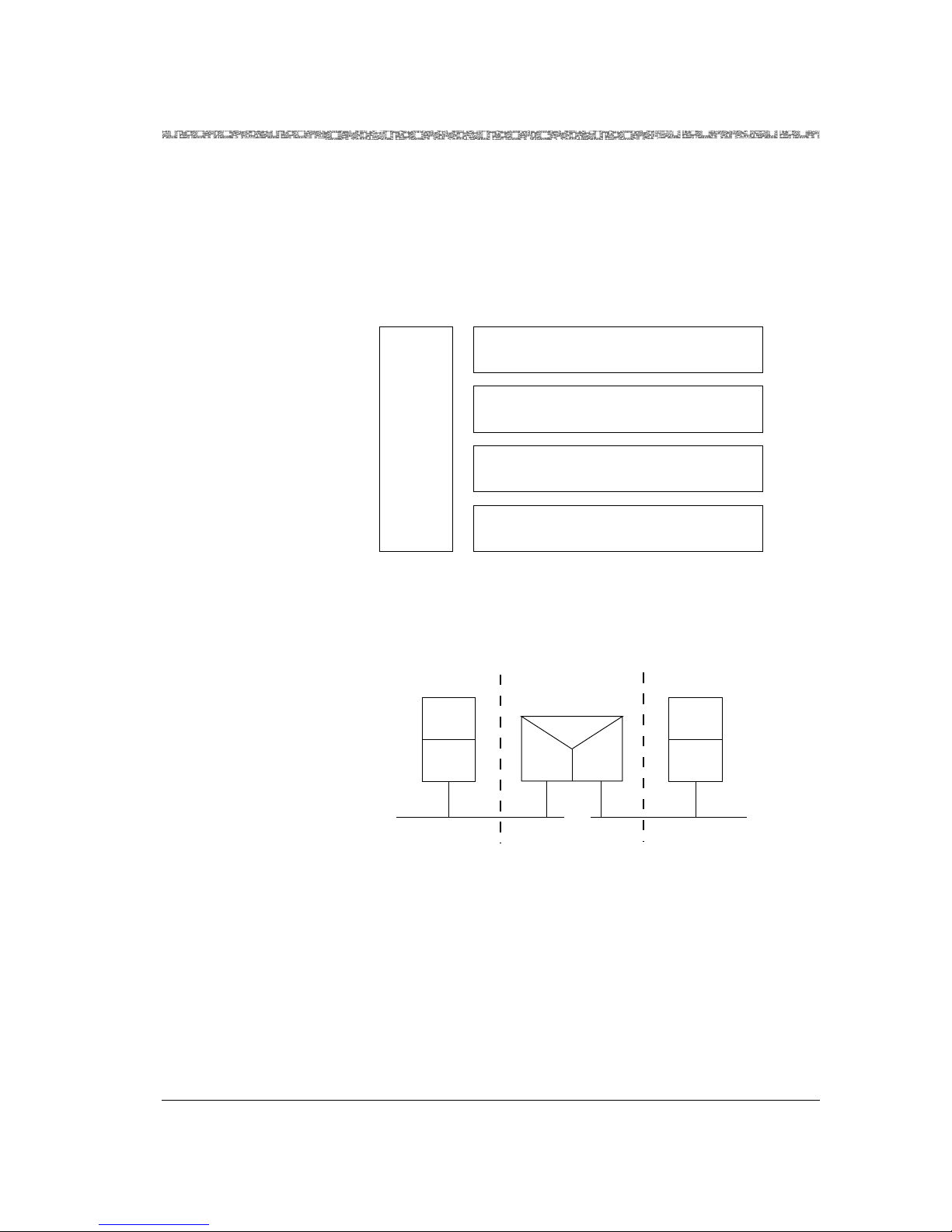
255-700-019 3-19
PacketStar™PSAX 20 Access Concentrator User Guide, Issue1 Release6.3.0
Chapter 3 System Features
PSAX 20 Software Features
Ethernet LAN Bridging
The Ethernet LAN bridging feature is provided on the Ethernet module. The
various functions and interfaces associated with Ethernet LANs are governed
by standards published by the Institute of Electrical and Electronics Engineers
(IEEE). The relationships of the various IEEE standards that affect LAN
bridging are shown in Figure 3-3.
Bridging is accomplished by relaying data from the MAC layer of one LAN to
the MAC layer of another LAN (see Figure 3-4).
Ethernet bridging over the ATM network is accomplished using ATM Forum
standards; that is, document RFC 1483, which specifies multiprotocol
encapsulation within ATM. Ethernet MAC data is encapsulated using ATM
Adaptation Layer 5 (AAL-5) and transported over the ATM network (see
Figure 3-5).
Figure 3-3. IEEE Protocols for Ethernet LANs (IEEE 802.1)
Figure 3-4. Ethernet Bridging via the MAC Layer (IEEE 802.1)
IEEE 802.3 Physical Layer
IEEE 802.3 CSMA/CD
Media Access Control (MAC) Layer
IEEE 802.1 Bridging
IEEE 802.2 Logical Link Control (LLC)
Layer
IEEE
802.1
Manage-
ment
LLC
Layer
End Station
LAN Bridge
Relay
MAC
Layer
MAC
Layer
MAC
Layer
LLC
Layer
End Station
LAN
MAC
Layer
Page 64

Chapter 3 System Features
PSAX 20 Software Features
3-20 255-700-019
PacketStar™PSAX 20 Access Concentrator User Guide, Issue1 Release6.3.0
The Ethernet LAN bridging feature incorporates the following functions:
• Bridging
Ethernet MAC layer data is encapsulated by using standards in the ATM
Forum document RFC 1483.
• Filtering
Certain Ethernet frames are filtered out and not relayed, according to a
filtering database. This frame filtering prevents frames from being
transmitted unnecessarily across the ATM network. The Spanning Tree
Algorithm and Protocol is the mechanism used to populate the filter
database dynamically.
• Bridge management
This function enables end users to manage configuration and
performance, and collect cell records and billing information. Standard
Ethernet MIBs, as defined in ATM Forum document RFC 1643, support
SNMP management.
• Performance
The Ethernet module provides simultaneous operation on all ports.
Firmware Release Control
Note: The Firmware Version Control window as described in the
procedure in the "Upgrading and Backing Up System Software
and Firmware" chapter should be used only on the advice of
Lucent Technologies NetworkCare (see the "Technical Support"
section in Chapter 1, "Getting Started.").
The Access Concentrator CPU has access to the firmware binaries of all
modules present in the access concentrator mainframe. The firmware is
downloaded into the RAM, into the secondary FLASH of each module,
through a dedicated communication channel.
Figure 3-5. Ethernet Bridging over an ATM Network (RFC 1483, AAL-5)
LLC
Layer
End Station
LAN Bridge
MAC
Layer
LLC
Layer
End Station
LAN
MAC
Layer
AAL5
RFC 14583
MAC
Layer
AAL5
RFC 14583
MAC
Layer
ATM
Page 65

255-700-019 3-21
PacketStar™PSAX 20 Access Concentrator User Guide, Issue1 Release6.3.0
Chapter 3 System Features
PSAX 20 Software Features
The firmware download is performed under the control of two Interworking
Functions (IWFs) resident in the Access Concentrator CPU, and in the I/O or
server module, respectively. Once the binaries are downloaded, the modules
execute the downloaded code that controls the module.
A user does not need to take the initiative to download an I/O or server
module’s firmware separately from the Access Concentrator CPU software
upgrade. When the Access Concentrator software is upgraded using the SRD
Download Configuration window (see Chapter 7, "Upgrading and Backing
Up the AC System Software"), the system reboots and all firmware of the I/O
and server modules (in the rebooted chassis) is also upgraded.
You can use the following procedure to revert to an older firmware release if
a module is not working properly with its current firmware.
Access Concentrator I/O modules released with Access Concentrator 6.0.0
software release are supported by the Firmware Release Control feature. The
I/O modules that were released before the Access Concentrator 6.0.0
software release will work in the Access Concentrator chassis, but are not
supported by the Firmware Release Control feature.
Forward Error Correction
The forward error correction (FEC) feature is a combination of functions
designed to protect data transmission in a noisy communications
environment, such as traffic transmitted across satellite and line-of-sight
radio-frequency circuits. Most of these types of circuits transmit at the rate of
2.048 Mbps or slower. The three stages of FEC are multiple redundancy
addressing, cell encoding, and cell scrambling. Since these FEC functions are
applied in conjunction with LANET, which helps maintain cell-delineation
capability up to random 10
-2
bit error rate (BER) with 0.625 percent
bandwidth overhead, maximum protection is obtained.
Multiple redundancy addressing sets up multiple virtual circuits to the same
destination. The addresses for the circuits are within the error space of the
principal one used for actual transmission. Thus, the most probable error
patterns occurring in the address field cause the address to be changed to
another valid one. To tolerate 2-bit random errors or 5-bit burst errors, 526
addresses are required for each channel. This is not a serious constraint
because high-noise, low-speed links are normally used by only a small
number of users. The more constraining situation, however, is that the
signaling channel VPI value 0 and VCI value 5 is within 2 bit-errors of the
null cell address (0,0). Thus, in high-error conditions, signaling is inhibited.
The PTI and GFC fields need to be separately protected with the payload. The
user needs only to set up a single connection using a VPI value 0 and a VCI
value in the range from 32 to 92. This provides for 60 simultaneous, noisetolerant base connections. Each connection (ATM-to-ATM, VCC, PVC) is
created between an ATM-enabled port on a Multi-Serial module and another
ATM port (such as the OC-3c and the STM-1 modules). Internally within the
Access Concentrator chassis, the connection is routed through the CPU
module for the cell-encoding stage.
Page 66

Chapter 3 System Features
PSAX 20 Software Features
3-22 255-700-019
PacketStar™PSAX 20 Access Concentrator User Guide, Issue1 Release6.3.0
Cell encoding is executed by the CPU module on cell payload data destined
for noisy interfaces. Based on a user-selected encoding rate for the
connection, source-data cell payloads are divided into six blocks and fed into
a Reed Solomon encoder. The encoded data, now approximately 48 bytes
larger, is loaded into new cell payloads and forwarded to the Multi-Serial
module for the cell-scrambling stage. The user selects a Reed Solomon
encoding rate with a specific error-correction capability, as follows:
• 1/2 rate
For each data cell, the encoder loads one redundant cell. This rate
provides correction of payload cells with 10
-3
BER to 10
-6
BER.
• 1/4 rate
For each set of three data cells, the encoder loads one redundant cell.
This rate provides correction of payload cells with 10
-4
BER to 0 BER.
• 1/8 rate
For each set of seven data cells, the encoder loads one redundant cell.
This rate provides correction of payload cells with 10
-5
BER to 0 BER.
• Dynamically changing rate options (see Table 3-6):
When the user selects the 1/2, the 1/4, or the 1/8 rate, the encoder maintains
that selected rate of encoding regardless of actual error conditions. When the
user selects one of the dynamically changing rate options, the encoder
employs the 1/2, 1/4, or 1/8 rate, dynamically adjusting the rate as needed,
depending on the number of errors encountered on the decoding side of the
circuit.
Cell scrambling is a function performed on the Multi-Serial module. This
function moves the first three bytes of the cell header (GFC, VPI, and VCI
fields) into the payload and spreads them out to protect against burst errors.
This action increases the burst error tolerance of the header from 5 bits to 54
bits with no cell loss.
Frame Relay-to-ATM Interworking
Any port on the Channelized DS3, Channelized STS-1e, Enhanced E1,
DS3 Frame Relay, and Multi-Serial modules, and the Enhanced DS1
component can be used to connect to a frame relay device. Frame relay-to-
Table 3-6. Rate Option
10
-3
Threshold
10
-4
Threshold
10
-5
Threshold
Automatic—low quality 1/2 rate 1/4 rate 1/8 rate
Automatic 1/2 rate 1/2 rate 1/8 rate
Automatic—high quality 1/2 rate 1/2 rate 1/4 rate
Bit Error Rate
Cell
Encoding
Rate
Page 67

255-700-019 3-23
PacketStar™PSAX 20 Access Concentrator User Guide, Issue1 Release6.3.0
Chapter 3 System Features
PSAX 20 Software Features
ATM interworking is performed at the network level Frame Relay Forum
FRF.5 and at the service level FRF.8. This allows the PacketStar™ Access
Concentrator to adapt and concentrate traffic from one frame relay network,
and transmit it to other frame relay or ATM networks. In this way, the Access
Concentrator acts as a gateway between routers, remote dial access servers,
IBM SNA equipment, and other devices configured for frame relay operation.
FRF.5 Encapsulating
Frames
With FRF.5 network level interworking, frames are encapsulated within ATM
cells at the network ingress point and "tunneled" through the ATM network.
At the network egress point, the ATM cell headers are removed and the
frames are reassembled for delivery to a frame relay device.
FRF.8 Converting
Frames
With FRF.8 service level interworking, frames are converted into one or more
ATM cells at the network ingress point. At the network egress point, the ATM
cells are delivered to an ATM device. This conversion is compliant with both
the FRF.8 implementation agreement and the IETF multiprotocol
encapsulation specifications (RFC1490, RFC1483). FRF.8 interworking is
performed at the end of the ATM network that connects to the frame relay
device.
Note: FRF.5 and FRF.8 are not interoperable and cannot be used at both
sides of a network. You may wish to use an FRF.8 approach for
applications involving interconnectivity between two frame relay
devices because the capabilities of FRF.8 include those which are
available with FRF.5.
Frame Relay-to-Frame-Relay Interworking
In addition to frame relay-to-ATM interworking, it is possible to configure an
Access Concentrator for strictly frame relay operation. A frame relay-toframe-relay connection can be made between two ports of an Access
Concentrator if both ports have frame relay capacity. In this case, frame relay
data received by one of the ports is converted to ATM cells for transmission
across the backplane of the Access Concentrator, and then converted back
into frame relay for transmission out of another port.
Integrated Link Management Interface (ILMI)
The integrated link management interface (ILMI) is network management
function that supports bidirectional exchange of ATM interface parameters
between two connected ATM Interface Management Entities (IMEs).
ILMI provides status information and statistics using Simple Network
Management Protocol (SNMP) and a MIB to provide any ATM device with
status and configuration information concerning the virtual path connections
(VPCs), virtual channel connections (VCCs), registered ATM network
prefixes, registered ATM addresses, and registered services and capabilities
available at its ATM interfaces. It also determines the operational status of the
logical port. ILMI is supported for all ATM UNI 3.0 and ATM UNI 3.1
interfaces.
Page 68

Chapter 3 System Features
PSAX 20 Software Features
3-24 255-700-019
PacketStar™PSAX 20 Access Concentrator User Guide, Issue1 Release6.3.0
Inverse Multiplexing over ATM (IMA)
Inverse multiplexing over ATM (IMA) creates virtual access pipes that are
faster than E-1, but not nearly as expensive as a T-3/E-3 line. This allows for
ATM capabilities without the costs associated with broadband access. The
DS1 IMA and E1 IMA I/O modules support the ATM IMA interface.
LANET Protocol
The LANET (Limitless ATM Network) protocol, coupled with a simple errortolerant addressing scheme, addresses the fundamental problem of noise in
adapting ATM to low-speed environments. LANET permits applicationdependent payload protection, allowing selective implementation of
bandwidth-costly, forward-error-correction techniques. It is designed to
identify and extract ATM cells at bit error rates as high as 10
-2
. A simple,
robust addressing scheme facilitates reliable delivery of ATM cells in a noisy
environment. By maintaining the cell extraction capabilities and
strengthening the cell-header error protection, LANET brings the advantages
of the ATM protocol to noisy, low-speed links.
The main features of LANET include the following:
• Regular framing-bit patterns that enhance cell delineation in high-noise
environments
• Compatibility with traditional link enhancement schemes such as
forward error correction (FEC) and bit interleaving
• Consistent interface to the higher layer of the protocol stack (that is, the
ATM layer)
• Transmission rate and media independence
• Natural synchronization with a standard 8-kHz telecommunication clock
The LANET solution permits both application-dependent payload protection
and link-quality-dependent header protection, while maintaining maximum
compatibility with ATM standards. Figure 3-6 shows the relationship
between LANET and the Open Systems Interconnection (OSI) model.
Page 69

255-700-019 3-25
PacketStar™PSAX 20 Access Concentrator User Guide, Issue1 Release6.3.0
Chapter 3 System Features
PSAX 20 Software Features
The LANET protocol is designed to be active in the upper end of the physical
layer of the OSI seven-layer model. Within a byte-oriented serial data stream,
LANET provides a framing structure around ATM cells for transmission
purposes and thus regular frame-marker bit patterns for cell extraction. Each
LANET frame (2400 bytes) is subdivided into 45 ATM cells (totaling 2385
bytes) with a 15-byte overhead. This structure permits a transmission rate
scalable according to the physical medium. The 15-byte overhead,
accounting for 0.63 percent of the bandwidth, includes the LANET frame and
subframe headers, which are used in conjunction with traditional cell-header
error-detection methods, such as header error correction (HEC), to enhance
cell delineation for noisy environments. The protocol thus becomes
independent of the transmission rate while still naturally synchronizing with
an 8-kHz transmission clock via the 2400 bytes-per-frame structure.
Traditionally, block-error correction schemes, such as Reed Solomon (RS)
coding, have been used to protect the header. As a simple alternative, the
Access Concentrator system software uses an error-tolerant addressing
scheme (multiple redundancy addressing) that establishes multiple virtual
circuits to the same destination, thus requiring no special hardware and no
modification to the current standard. The addresses for the circuits are within
the error space of the principal address used for actual transmission. Thus,
the most probable error patterns occurring in the address field will simply
change the address to another valid one. This approach maintains
independence from the application layer because it encodes the header
Figure 3-6. The Relationship Between LANET and the OSI Model
Layer 2
Layer 3
Layer 4
Layer 5
Layer 6
Layer 7
LANET Protocol
Encryption Error Correction Bit Interleaf
Satellite Radio Land Lines
ATM
Voice Video Images Data
SERVICE-INDEPENDENT ARCHITECTURE
Layer 1
From bits per second to megabits per second
CELL-BY-CELL ENC RYPTION
Page 70
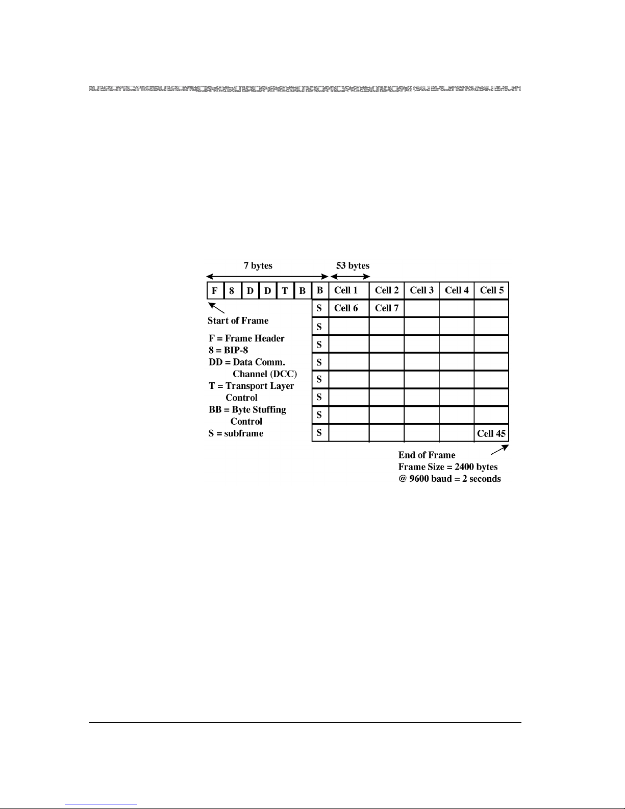
Chapter 3 System Features
PSAX 20 Software Features
3-26 255-700-019
PacketStar™PSAX 20 Access Concentrator User Guide, Issue1 Release6.3.0
address within the same 10-nibble header space of standard ATM cells. In
addition, it avoids the extra delay (detrimental to CBR traffic) required of
multiple header-encoding schemes. In practice, to tolerate 2-bit random
errors or 5-bit burst errors will require setting up 526 addresses per each
channel. This is not a serious constraint because high-noise and low-speed
links will likely be used to support only a small number of users.
Finally, given the ability to deliver cells, the payload can now be FECprotected on a per-virtual-circuit basis depending on the error tolerance of
the application at the service-specific convergence sublayer (SSCS).
Figure 3-7 shows the LANET frame structure.
The LANET subframe functions in the following ways:
• The timely arrival of the header patterns is used as a confidence check,
confirming that the system is properly synchronized.
• In the event of synchronization loss, a state machine can easily seek and
resynchronize to the regular appearance of the simple header patterns.
Operations, Administration, and Maintenance (OAM)
Overview The Operations, Administration, and Maintenance (OAM) feature on the
PSAX 2300 and PSAX 1250 chassis detects and reports on abnormal behavior
in virtual path connections (VPC) and virtual channel connections (VCC) in
the ATM and physical layers associated with an ATM network. OAM affects
the system software and I/O module firmware associated with generating,
Figure 3-7. LANET Frame Structure
Page 71

255-700-019 3-27
PacketStar™PSAX 20 Access Concentrator User Guide, Issue1 Release6.3.0
Chapter 3 System Features
PSAX 20 Software Features
receiving, and intrepreting F4/F5 OAM flows. This feature requires the user
to run AQueWin™ and the AQueView™ system.
OAM Functions The OAM functions (and their cell types) are:
• Fault management
~ detection (continuity check): periodically verifiy connection integrity
~ reporting (alarm indication signals [AISs]) and remote defect
indications [RDIs]: periodically notify connection faults in upstream
and downstream directions
~ localization (loopback): isolate failed entities if defect information is
insufficient
• Activation/deactivation: remote activation/deactivation of continuity
check functions
OAM Cell
Characteristics
OAM cells are bidirectional and follow the same physical and logical route as
user payload cells. There are two variants for each flow: one that checks a
particular segment, and the other, an end-to-end flow. A segment is indicated
by a virtual channel identifier (VCI) of three for F4 flows, or a payload type
(PT) of 4 for F5 flows. End-to-end flows are indicated by a VCI of 4 for F4
flows, or a PT of 5 for F5 flows.
OAM cells are ATM cells with the fields shown in Figure 3-8:
• Header: this is the same as the ATM cell header
• OAM Cell Type: the management type (fault, activation/deactivation)
• OAM Function Type: the specific function (AIS, RDI, continuity check,
loopback, forward monitoring, backward reporting, and so on)
• Function-specific field: data required for the specific function
• Reserved: reserved for further specification
• EDC: CRC-10 error detection code computed over the cell payload
(except the CRC-10 field) and used to check for data corruption
F4/F5 Flows OAM has two flows of management information: F4 and F5. F4/F5 in-band
maintenance flows are defined at the ATM layer for the VPC and VCC level,
respectively. F4 is used for path level connections, where the virtual path
(VP) flows are identified by reserved values within the path. F5 is used for
Figure 3-8. OAM Cell Fields
Function
Type Reserved
OAM
Cell
Type
EDCFunction specific field
Payload
Header
Header
44 6 10360 bits (45 bytes)
Page 72

Chapter 3 System Features
PSAX 20 Software Features
3-28 255-700-019
PacketStar™PSAX 20 Access Concentrator User Guide, Issue1 Release6.3.0
circuit level connections, where the circuit virtual channel (VC) flows are
identified by the payload type (PT) values.
Characteristics of OAM F4 Cells
• Bidirectional
• Have the same VPI value as user cells for VPC
• Identified by one or more preassigned VCIs for both directions
• In the same physical route for fault correlation and performance
information
Characteristics of OAM F5 Cells
• Bidirectional
• Have the same VPI/VCI values as the user cells for the VCC
• Adentified by one or more preassigned VCIs for both directions
• In the same physical route for fault correlation and performance
information
Fault Management Functions
Alarm surveillance functions are designed to aid in physical layer detection
and notification of network faults. Alarm surveillance measures are
performed on a continuous basis by features within network elements and
management systems. They monitor network elements for anomalies,
defects, and failures.
The three major aspects of the fault management functions are:
• Detecting
• Reporting
• Localizing
Detection Detection (continuity checks): periodically verifies connection integrity.
The activation/deactivation OAM mechanism is used to remotely start and
stop the generation of cells that perpetually monitor performance and
continuity. These mechanisms can indicate to the far end a connection is
alive, even if no user data traffic has been recently transmitted. When a
connection activates the continuity mechanism, continuity check cells are
inserted by the originating end point, either at predefined time intervals (for
example, a few seconds apart), or when the connection has been idle for a
given time interval (for example, a second to two seconds).
Continuity Checks at Connection or Segment End Points
End points, either connection or segment, use activation procedures to
request continuity checking with the opposite end point. The requesting end
point specifies the direction of the continuity checking (from the requesting
end point, to the requesting end point, or both directions). If the far end
Page 73

255-700-019 3-29
PacketStar™PSAX 20 Access Concentrator User Guide, Issue1 Release6.3.0
Chapter 3 System Features
PSAX 20 Software Features
accepts the request, the specified source point(s) starts sending continuity
checks periodically to the receiving point.
A source may send continuity check cells independently of the user’s cells
sent. Source continuity check cells are sent at predefined intervals of one per
second when no user cells have been sent within one second.
If a point along the continuity check route does not receive a user cell or
continuity cell within 3.5+/- 0.5 seconds, it assumes a loss of continuity
(LOC) fault and sends AIS cells downstream. The continiuty check receiving
point declares an AIS state and sends remote defect indication (RDI) cells
upstream to the source, indicating the interruption of cell transfers in the
downstream direction. When the connection is re-established and user or
continuity check cells are received again, the affected points remove the LOC
fault condition and stop sending AIS/RDI cells.
Continuity Checks at VPC or VCC End or Connecting Points
A VPC or VCC end or connecting point (the source) sends an activation or
deactivation request to the receiving point. The receiving point responds by
either confirming or denying the request. On receiving an activation
confirmation, the source or receiving point (depending on the direction of
the action) periodically generates performance management or continuity
check cells.
Reporting Reporting AIS and RDI: periodic notification when connection faults in the
upstream and/or downstream direction among various network elements are
affected by a defect.
Alarm Indication Signals
A network element (NE) transmits an AIS alarm downstream when it
receives a major alarm condition such as a loss of frame. This prevents the
generation of unnecessary alarms, and maintains communications.
A VPC or VCC connecting point receives an F4/F5 AIS alarm and sends AIS
cells periodically (usually one per second) downstream, notifying all
intermediate points in the connection of a fault.
F4/F5 AIS alarms are generated when a network element receives one of the
following failure indications from the physical layer:
• LOS (Loss of Signal) alarm
The LOS alarm indicates there are no transitions occurring in the NE
received signal. For optical interfaces, an all ones pattern results after
receiving no light pulses for a prescribed period. For electrical interfaces, a
consecutive zero pattern results after receiving no signal transitions.
You can simulate a LOS with an optical interface by turning the laser off.
• LOF (Loss of Frame) alarm
The LOF alarm indicates the receiving equipment has lost frame
delineation.
Page 74

Chapter 3 System Features
PSAX 20 Software Features
3-30 255-700-019
PacketStar™PSAX 20 Access Concentrator User Guide, Issue1 Release6.3.0
You can stimulate a LOF alarm by injecting a frame word error by using
the Generate Frame Error dialog box.
• LOP (Loss of Pointer) alarm
The LOP alarm indicates the receiving equipment has lost the pointer to
the start cell in the payload.
• P-AIS (Path Alarm Indication Signal)
The P-AIS alarm can occur on a SONET interface.
• LOCS (Loss of Cell Synchronization) alarm
A LOCS alarm is generated by a NE at the convergence layer. It enters a
LOCS state when it receives seven successive bad cell headers, and exits
the LOCS state when it correctly receives six valid cell headers.
LOCS is not used when PLCP framing is present.
LOCS is only displayed in seconds.
Remote Defect Indications
The VPC/VCC end point sends RDI cells in the backward direction to the far
end point, in order to indicate the interuption of cell transfers in the forward
direction.
F4/F5 RDI alarms are generated when a network element receives one of the
following failure indications from the physical layer: The failure indications
are exactly the same as those listed for AIS.
Note: The F4 RDI alarm was formerly called the F4 FREF alarm. The F5
RDI alarm was formerly called the F5 FERF alarm.
Localization Localization (loopback): isolation of failed entities if defect information is
insufficient.
Loopback check: The detection of faults in the physical and ATM layers, and
the detection of defects and declaration of failures within the network
elements. A VPC or VCC end or connecting point sends a loopback cell to a
destination end or connecting point. If the source receives a looped cell back
within five seconds, the loopback is considered successful. If the source does
not receive a successful loopback, it declares a time out.
Loopback check supports the following applications:
~ End-to-end loopback: An end-to-end loopback cell is inserted by an
end point, and looped back by the corresponding far-end end point.
~ Access line loopback: A segment loopback cell is inserted by the
customer or the network, and looped back by the first ATM node (at
the VP/VC level) in the network or customer equipment respectively.
For this application, the segment is defined by mutual agreement.
~ Interdomain loopback: A segment loopback cell is inserted by one
network operator and looped back by the first ATM node (at the
VP/VC level) in an adjacent network operator domain. For this
application, the segment is defined by mutual agreement.
Page 75

255-700-019 3-31
PacketStar™PSAX 20 Access Concentrator User Guide, Issue1 Release6.3.0
Chapter 3 System Features
PSAX 20 Software Features
~ Network-to-endpoint loopback: An end-to-end loopback cell is
inserted by one network operator, and looped back by the end point in
another domain.
~ Intradomain loopback: A segment loopback is inserted by a
connection/segment end point or a connecting point, and looped back
by a segment or a connecting point. For this application, the use of the
loopback location identifier is a network operator option.
Activation/Deactivation
Activation/deactivation is an in-service OAM mechanism used to remotely
start and stop the generation of cells that perpetually monitor performance
and continuity.
A VPC or VCC end or connecting point (the source) sends an activation or
deactivation request to the receiving point. The receiving point responds by
either confirming or denying the request. On receiving an activation
confirmation, the source or receiver (depending on the direction of the
action) periodically generates performance management or continuity check
cells.
Characteristics of
OAM Activation /
Deactivation Cells
The activation/deactivation cells are OAM cells with the function-specific
fields shown in Figure 3-9.
• Message ID: indicates whether to request, confirm, or deny the activation
or deactivation of cells
• Directions of Action: direction (s) in which to start/stop generating
performance management or continuity cells
~ A-B (ingress): away from the activator/deactivator
~ B-A (egress): toward the activator/deactivator
~ both: bidirectional
• Correlation Tag: number used to correlate transmitted
activation/deactivation requests with their responses
• PM Block Size (A-B, B-A): This feature works with activation requests
only. It monitors the size of user cell blocks used to monitor the
performance in the forward or backward direction (default is 1,024 cells).
Figure 3-9. OAM Activation/Deactivation Cells
Message
ID
Directions
of Action
Correlation
Tag
PM Block
Size A-B
PM Block
Size B-A
Unused
6 2 8 4 4 336 bits (42 bytes)
Page 76

Chapter 3 System Features
PSAX 20 Software Features
3-32 255-700-019
PacketStar™PSAX 20 Access Concentrator User Guide, Issue1 Release6.3.0
Module-Specific Alarm Functions
Loss of Signal (LOS) Module: DS1 IMA
A network element (NE) will transmit an AIS alarm when it enters the LOS
state for 2.5 +/- 0.5 seconds. This occurs when the NE has detected 175 +/75 consecutive pulse positions with no positive or negative pulses.
• The AIS alarm is stopped by the NE when it detects an average pulse
density of at least 12.5% with no more than 15 consecutive zeros over a
perioid of 175 +/-
75 pulse positions, starting with receiving a pulse.
• The AIS alarm continues if, at the end of the pulse position interval, any
subintervals of 100 pulse positions containing no pulses of either polarity
are observed.
• The AIS alarm is cleared when the LOS state is absent for 20 seconds.
Modules: Channelized DS3, DS3 IMA, DS3 ATM, DS3 Frame Relay
A network element (NE) will transmit an AIS alarm downstream when a
LOS state persists for 2.5 +/- 0.5 seconds. This occurs when the NE has
detected 175 +/- 75 consecutive zeros, or no pulses on an incoming signal.
• The AIS alarm is stopped by the NE when it receives an average pulse
density of at least 33% over a period of 175 +/- 75 consecutive pulse
positions, starting with receiving a pulse.
• The AIS alarm continues if, at the end of the pulse-position interval, any
subintervals of 100 pulse positions containing no pulses of either polarity
are observed.
• The AIS alarm is cleared when the LOS state is absent for 10.0 +/- 0.5
seconds.
Modules: E1 IMA, High-Density E1
A network element (NE) enters the LOS state when there is an absence of
signal transitions on the incoming signal for a period of 5 milliseconds to 1
microsecond.
• The AIS alarm is cleared when the LOS state is absent for 3 seconds.
Module: E3 ATM
A network element (NE) will transmit an AIS alarm when it enters a Loss of
Signal (LOS) state after not detecting input for 32 clock cycles.
• The AIS alarm is stopped by the NE as soon as it receives an input signal.
Modules: OC-3 MM APS, OC-3 MMAQ, OC-3 MMTS, Oc-3 SM APS, OC-3
SMAQ, OC-3 SMTS
A network element (NE) will transmit an L-AIS (line AIS in SONET) alarm
downstream within 100 milliseconds of the onset of all zeros. This occurs
when the receiver declares a Loss of Signal (LOS) after a violating period (20
+/- 3 milliseconds) of consecutive all zero bytes, or zero optical power, is
detected in the received signal.
Page 77

255-700-019 3-33
PacketStar™PSAX 20 Access Concentrator User Guide, Issue1 Release6.3.0
Chapter 3 System Features
PSAX 20 Software Features
• The L-AIS alarm is cleared after the receiver removes an LOS. This occurs
when two valid framing patterns (A1, A2) are received and no violations
have been detected.
Modules: STM-1 MM MSP, STM-1 MMAQ, STM-1 MMTS, STM-1 SM MSP,
STM-1 SMAQ, STM-1 SMTS
A network element (NE) will transmit an MS-AIS alarm downstream within
100 microseconds of the onset of all zeros. This occurs when the receiver
declares a Loss of Signal (LOS) after a violating period (20 +/- 3
microseconds) of consecutive all zero bytes, or zero optical power, is detected
in the received signal.
• The MS-AIS alarm is cleared after the receiver removes an LOS. This
occurs when two valid framing patterns (A1, A2) are received and no
violations have been detected.
Loss of Frame (LOF) Modules: Channelized DS3, DS1 IMA
A network element (NE) will transmit a Loss of Frame (LOF) alarm when an
Out of Frame (OOF) condition persists for 2.5 seconds +/- 0.5 seconds
(except when the AIS defect or failure is present.)
• The LOF alarm stops when the NE detects valid framing for 20 seconds or
when the AIS defect is detected.
Modules: DS3 IMA, DS3 ATM, DS3 Frame Relay
A network element (NE) will transmit a Loss of Frame (LOF) alarm when an
Out of Frame (OOF) condition persists for 2.5 seconds +/- 0.5 seconds.
• The LOF alarm stops when the NE detects valid framing for 10.0 seconds
+/- 0.5 seconds.
Modules: E3 ATM, OC-3 MM APS, OC-3 MMAQ, OC-3 MMTS, OC-3 SM
APS, OC-3 SMAQ, OC-3 SMTS, STM-1 MM MSP, STM-1 MMAQ, STM-1 SM
MSP, STM-1 SMAQ, STM-1 SMTS
A network element (NE) will transmit a Loss of Frame (LOF) alarm when an
Out of Frame (OOF) condition persists for 3 milliseconds or longer.
• The LOF alarm stops when the NE receives a valid signal for 3
milliseconds.
Note: In order to account for intermittent out-of-frame conditions, the 3
milliseconds time is not reset to zero until an in-frame condition
persists for more than 3 milliseconds.
Alarm Indicator
Signal (AIS)
Module: DS1 IMA
A network element (NE) will transmit an AIS alarm when it detects a defect
on the unframed, all ones AIS signal for 2.5 seconds +/- 0.5 seconds, or when
it detects a Loss of Frame (LOF). In this situation, the NE will also transmit a
RAI upstream.
• The AIS alarm stops when the NE receives a valid signal for 20 seconds.
Page 78

Chapter 3 System Features
PSAX 20 Software Features
3-34 255-700-019
PacketStar™PSAX 20 Access Concentrator User Guide, Issue1 Release6.3.0
Modules: Channelized DS3, DS3 IMA, DS3 ATM, DS3 Frame Relay
A network element (NE) will transmit an AIS alarm when it detects an AIS
defect that persists for 2.5 +/- 0.5 seconds. In this situation, the NE will also
transmit RDI upstream.
• The AIS alarm stops when the NE receives a valid signal for 10.0 seconds
+/- 0.5 seconds.
Modules: E1 IMA, Enhanced E1, High-Density E1
A network element (NE) will transmit an AIS alarm when the defect of two
or fewer zeros in each of two consecutive double frame periods (a total of
512 bits) is detected.
• The AIS alarm stops when the NE receives either of the following:
~ two consecutive double frame periods (a total of 512 bits) containing
three or more zeros
~ A frame alignment signal error
Module: E3 ATM
A network element (NE) will transmit an all ones AIS downstream when it
detects a loss of signal (LOS) or loss of frame (LOF). In this situation, the NE
also transmits a far-end remote failure (FERF) alarm upstream.
Remote Defect
Indications
Modules: Channelized DS3, DS3 IMA, DS3 ATM, DS3 Frame Relay
A network element (NE) will transmit an RDI when it detects a severely
errored frame (SEF) or AIS (if implemented) for 2.5 seconds +/- 0.5 seconds.
• The RDI alarm stops when the NE’s received failure stops for 10.0 seconds
+/- 0.5 seconds.
E1 IMA, Enhanced E1, High-Density E1
A NE will transmit a RDI alarm upstream when a “1” in bit 3 in Non-FacilityAssociated Signaling (NFAS) frames is detected.
• The RDI alarm stops .6 seconds after the condition has been removed.
Soft Permanent Virtual Circuits
The soft permanent virtual circuit (SPVC) feature is a semi-permanent virtual
circuit enabled by management action. It is a PVC-type circuit in which SVCs
are used for call setup and (automatic) rerouting. Once either a PVC or a
permanent virtual path connection has been configured, an SPVC can be
established between the two network interfaces serving the PVC by using
signaling procedures. Consequently, this type of connection has attributes of
both a switched virtual connection and a permanent virtual connection.
Specifically, an SPVC is established and released between the two network
interfaces (NIs) serving the PVC. The user assigns unique ATM addresses,
including the SEL octet in the case of a private ATM address (see Section 3.1
of UNI 4.0 signaling specification), to the corresponding NIs, thus identifying
the startpoint and endpoint of the SPVC.
Page 79

255-700-019 3-35
PacketStar™PSAX 20 Access Concentrator User Guide, Issue1 Release6.3.0
Chapter 3 System Features
PSAX 20 Software Features
Using the PacketStar™ Access Concentrators, you can make a maximum of
30,000 connections per node, and a maximum of 5,000 SPVC connections
per node.
Release 6.3 implements Phase 2 of a multiphase development program to
eventually improve ATM traffic management on all modules except DS3 and
E3. Over several development phases, Lucent will add new service classes
and expand feature coverage on ATM interface modules. Phase 1 added
traffic management to the OC-3c APS and the STIM-1 MSP modules. Phase 2
gives this capability to the Channelized DS3, DS1 and E1 modules.
One of the main improvements is upgraded usage parameter control (UPC).
This feature allows the end system to check the validity of the ATM
connection and protect it from malicious or unintentional misbehavior that
could affect the quality of service (QoS) of established connections. After a
set of service categories is specified, UPC is given a set of parameters for each,
describing the traffic presented to the network and the quality of service the
network requires. A number of traffic control mechanisms are defined,
which the network may use to meet the QoS objectives.
Switched Virtual Circuits
Switched virtual circuit (SVC) connections are used for voice traffic over a
public ATM WAN or private line network. SVCs are supported on all the ATM
cell-bearing interfaces, including the DS3, E3, OC-3c, STM-1, Multi-Serial,
and High Speed modules. The Access Concentrator system software supports
the following features:
• Each ATM port on a single module can be individually configured for
ATM UNI 3.0, UNI 3.1, IISP user, IISP network, or PNNI interfaces.
• SVCs can be allocated on UNI (public and private), IISP, and PNNI
interfaces.
• Point-to-point and point-to-multipoint VCC connections are supported.
• VCC connections support both symmetric and asymmetric bandwidth
requirements.
• The Access Concentrator system can process 60 calls per second, 100
maximum UNIs per system, 5,000 maximum simultaneous point-topoint SVC call originations, and 2,000 maximum point-to-multipoint call
originations.
• The Access Concentrator system (equipped with 64 MB of memory on
the CPU module) can process 20,000 maximum simultaneous SVC calls
in progress.
• The individual call setup time is 16 milliseconds (ms) maximum, while
the minimum call setup time for SVCs is approximately 10 ms from the
time the call setup message enters the CPU module, and the
acknowledgment leaves the CPU module.
Page 80

Chapter 3 System Features
PSAX 20 Software Features
3-36 255-700-019
PacketStar™PSAX 20 Access Concentrator User Guide, Issue1 Release6.3.0
Using the PacketStar™ Access Concentrator, you can make a maximum of
30,000 PVC connections per node, a maximum of 10,000 SVC point-to-point
connections per node, and a maximum of 6,000 SVC point-to-multipoint
connections per node.
Functional
Description
SVC signalling, per ATM Forum UNI 3.0 and UNI 3.1, is selectable on a perport basis. Call control is performed on the CPU module, including
management of the call-state transitions for each of the calls. This process
allows on-demand allocation of bandwidth and connection resources. The
signaling protocol supports the following basic functions at the UNI interface:
Call States Call states exist on both the user side and the network side of the transaction.
Call states define which messages can be accepted by the user or the network
entity, and how they are expected to react to those messages. As the user or
network entity moves from call state to call state, the call switching process is
accomplished.
In cases where the calling party is the user, and the called party is across the
network, the UNI at the Access Concentrator port presents a user-side
interface (UNI) to the user. The Access Concentrator port receives these userside messages from the user and based on resource availability, route
determination, and other network factors, presents a network-side (NNI or
IISP) interface to the called party or the network-side Access Concentrator
Feature Description
Connection/Call Setup Origination/establishment of a call.
Connection/Call Request Request of resources for connectivity to a
certain destination. The Information Element (IE) field contains resource information, that is, PCR, SCR, MBS, QoS class,
and so on.
Connection/Call Answer Allows the destination party to respond to a
request with VPI/VCI and other information related to the connection/call.
Connection/Call Clearing Provides the information associated for
removing the call/connection request. This
includes: 1) calls removed because there
weren’t enough resources to meet the call
request, or 2) connections removed due to
call disconnect requests from either party,
or 3) calls removed due to link and other
network failures.
Reason for Clearing Allows the clearing party to indicate the
cause for initiating its removal from a connection/call.
Page 81

255-700-019 3-37
PacketStar™PSAX 20 Access Concentrator User Guide, Issue1 Release6.3.0
Chapter 3 System Features
PSAX 20 Software Features
port. Both user-side and network-side interfaces undergo similar state
transitions. Transition messages trigger these call-state changes as follows:
Call States Description
#0—Null No call exists.
#1—Call initiated • User—Outgoing call when the user requests call
establishment from the network.
• Network—Received the call establishment
request, but has not responded yet to the outgoing
call.
#3—Outgoing call
proceeding
• User—Outgoing call when the user receives an
acknowledgment that all call information required
for call establishment has been received from the
network.
• Network—Network has sent an acknowledgment
to the user that all call information has been
received.
#6—Call present • User—For incoming calls, the user has received
the call establishment request, but has not
responded yet.
• Network—For incoming calls, the user has sent
the call establishment request, but has not
received a satisfactory response.
#8—Connect request • User—For incoming calls, when the user has
answered the call and is waiting to be awarded the
call.
• Network—For incoming calls, when the network
has received an answer but the network has not
yet awarded the call.
#9—Incoming call
proceeding
• User—For incoming calls, when the user has sent
acknowledgment that the user has received all call
information necessary to establish a call.
• Network—For incoming calls, when the network
has received acknowledgment that the user has
received all call information necessary to affect call
establishment.
Page 82

Chapter 3 System Features
PSAX 20 Software Features
3-38 255-700-019
PacketStar™PSAX 20 Access Concentrator User Guide, Issue1 Release6.3.0
The following state transition messages are used for ATM point-to-point call
and connection control:
• The information elements used in the Call Establishment-Setup message
allow the user to request the called party number, specific PCR, SCR,
MBS, QoS class, forward and backward direction rates, performance,
congestion control parameters, and so on, from the Access Concentrator
UNI. The Call Establishment-Connect message allows the called party to
respond with available traffic parameters, such as PCR, SCR, MBS, QoS
class, forward and backward direction rates, performance, congestion
control parameters, and so on. Usually this message also indicates the
available VPI/VCI allocated for the connection. The other state-transition
messages are specified by the ATM Forum UNI 3.0 and UNI 3.1
specifications and are transparent to the user.
#10—Active • User—For incoming calls, when the user has been
awarded the call. For outgoing calls, when the
user has received an indication that the remote
user has answered the call.
• Network—For incoming calls, when the network
has awarded the call to the called user. For outgoing calls, when the network shows that the remote
user has answered the call.
#11—Release
request
• User—The user has requested that the network
clear the end-to-end connection and is waiting for
a response.
• Network—The network has requested a request
from the user to clear the end-to-end connection.
#12—Release indication
• User—The user has received an indication to disconnect because the network has disconnected the
end-to-end connection.
• Network—The network has disconnected the endto-end connection and has sent an indication to
disconnect the user-to-network connection.
Call establishment messages:
• Call proceeding
• Connect
• Connect acknowledgment
•Setup
Call clearing messages: • Release
• Release complete
Miscellaneous messages: • Status
• Status inquiry
Call States Description
Page 83

255-700-019 3-39
PacketStar™PSAX 20 Access Concentrator User Guide, Issue1 Release6.3.0
Chapter 3 System Features
PSAX 20 Software Features
Traffic Shaping
The traffic shaping feature is a method for controlling the flow of data traffic.
It is implemented in firmware on modules that are offered with trafficshaping variations. Those modules are the OC-3c Multi-Mode, OC-3c SingleMode, STM-1 Multi-Mode, and STM-1 Single-Mode modules.
Traffic shaping ensures that variable bit-rate (VBR) traffic entering the Access
Concentrator system (via the OC-3c and the STM-1 modules) complies with
the parameters of established service contracts. If bursty VBR traffic exceeds
the parameters of the output connection, the rate of the traffic flow is
controlled to comply with the specified output rate by means of an input cellselection algorithm before the traffic flow reaches the Access Concentrator
backplane. If traffic exceeds the buffer capacity of the OC-3c or the STM-1
module (that is, rises above the maximum-capacity level), cells are discarded.
Traffic shaping allows the network side of the Access Concentrator system to
multiplex more efficiently the traffic-shaped virtual channel connections
(VCCs) with other customer premises equipment (CPE) traffic (voice, video,
and so on) for transport across the ATM network link. Constant bit-rate
(CBR) traffic is unaffected by traffic shaping.
The only application of the traffic-shaping module is shown in Figure 3-10.
An end user has an ATM DS3 network connection and has subscribed to a
VBR VCC connection contract from a carrier (service provider) with the
following traffic parameters: 1) sustained cell rate (SCR) is 40,000
cells/second; 2) peak cell rate (PCR) is 80,000 cells/second; and 3) maximum
burst size (MBS) is 250 cells. Even though LAN switches usually maintain a
sustained cell-transport rate of 40,000 cells/second, they allow LAN traffic to
burst in violation of carrier traffic contracts, causing clusters of cells to exceed
the MBS parameter. Because carriers monitor traffic at the edge of a network
and enforce adherence to traffic contracts by discarding cells that exceed the
Figure 3-10. Traffic-Shaping Application
ATM
Network
LAN
ATM
Switch
LAN
ATM
Switch
Bursty LAN ATM Traffic
Bursty LAN ATM Traffic
ATM
ATM
OC-3c OC-3c
DS3 DS3
Shaped Traffic
to Comply with
ATM Service Contract
PacketStar
Access Concentrator
PacketStar
Access Concentrator
Page 84

Chapter 3 System Features
PSAX 20 Software Features
3-40 255-700-019
PacketStar™PSAX 20 Access Concentrator User Guide, Issue1 Release6.3.0
MBS parameter, end users whose traffic violates their contractual MBS
parameter experience high cell loss (and hence high packet loss). With the
traffic-shaping feature of the OC-3c and the STM-1 modules, the Access
Concentrator system effectively smooths bursty input LAN traffic to comply
with the carrier traffic contract.
The input cell-selection buffering scheme is shown in Figure 3-11.
Connected to the LAN ATM switch via an ATM OC-3c or STM-1 link, the
OC-3c and the STM-1 modules with traffic shaping support a total of 119
VCCs and VPCs. All inbound traffic is processed by the input cell selection
algorithm, dynamically shared by all VCCs and VPCs, which smooths the
traffic. The module buffer of the OC-3c or the STM-1 module is always 4 MB
smaller than the total amount of memory installed on the module. For
example, if 8 MB of memory are installed, 4 MB are available for queuing; if
32 MB of memory are installed, 28 MB are available for queuing. This
dynamically shared buffer allows inbound VBR traffic to burst up to the line
rate.
The module buffer of the OC-3c or the STM-1 module is set up with a
maximum-capacity level (defined as 31/32 of the buffer size), and a
minimum-capacity level (defined as 3/4 of the buffer size). When the
incoming cells exceed the maximum-capacity level, the input cell-selection
algorithm starts discarding cells to maintain a smooth traffic flow. The
algorithm discards traffic on the connection with the longest queue first, then
traffic on the connection with the second longest queue, and continues on
until the module buffer of the OC-3c or the STM-1 module reaches the
minimum-capacity level.
Figure 3-11. Traffic Shaping Using the Input Cell-Selection Algorithm
Page 85

255-700-019 3-41
PacketStar™PSAX 20 Access Concentrator User Guide, Issue1 Release6.3.0
Chapter 3 System Features
PSAX 20 Software Features
The algorithm processes traffic moving out of the input cell selection buffer
according to the SCR of the particular VPC/VCC. The MBSs of traffic-shaped
output are set as follows:
The OC-3c and the STM-1 modules can perform traffic shaping on multiple
high-rate connections (such as three 40-Mbps connections). Assigning a SCR
to a connection above 75 Mbps, however, is not recommended in sensitive,
bursty traffic environments. Assigning a SCR above 120 Mbps will essentially
eliminate any traffic shaping, and thus is strongly discouraged.
• The OC-3c and the STM-1 modules perform only limited traffic
management on the output side. The output buffer is limited to 2 Mbps
for VBR traffic and 128 cells for CBR traffic, with only three priority levels
supported: CBR, VBR1, and VBR2. The maximum-capacity level for
congestion control is 32,000 cells, and the minimum-capacity level is
24,576 cells, with VBR traffic being shut off first from the backplane.
Voice Compression
A noncompressed voice channel uses 64 Kbps of bandwidth. Voice
compression reduces the 64 Kbps bandwidth to a lower value, based on the
algorithm chosen. Compressed voice messages can be carried over ATM
Adaptation Layer 2 (AAL-2) only. The software on the CPU module assumes
a 30 percent bandwidth savings.
Voice compression over AAL-2 will only work for a voice channel that is
connected to an Access Concentrator through an ISDN PRI line. This is
because AAL-2 does not transfer the voice channel signaling bits. If silence
detection is enabled for a voice compression channel and no voice is
detected, no ATM cell will be sent.
Voice Processing
With the DSP2C module, the Access Concentrator system can process voice
traffic on selected DS0 circuits within the DS1 connections of the system.
This module, a significant improvement over the earlier DSP2A and DSP2B
server modules, processes ciruit emulation voice messages and can apply
voice compression, echo cancellation, silence suppression, and comfort noise.
Used with the channelized circuit emulation service modules, the DSP2C
offers superior voice processing capability through the PacketStar™ line for
the Lucent voice traffic over ATM (VToA) solution.
Sustained Cell Rate
(SCR) of VPC/VCC
Maximum Burst Size (MBS) of Traffic-
Shaped Output
0–20 Mbits/sec. < 4 cells
20–30 Mbits/sec. < 5 cells
30–40 Mbits/sec. < 6 cells
75–120 Mbits/sec. approximately 20–50 cells
Page 86

Chapter 3 System Features
I/O, Optical, and Server Modules
3-42 255-700-019
PacketStar™PSAX 20 Access Concentrator User Guide, Issue1 Release6.3.0
The DSP2C module supports ATM Adaptation Layer 2 (AAL-2) SVC
connections and PVC multiplexing for reduced call latency.
To protect facsimile transmissions, the DSP2C module automatically turns off
voice processing and echo cancellation on any channel when it detects a
modem tone.
Figure 3-12 illustrates how an Access Concentrator system using voice
processing might be deployed in a combined voice/data network.
I/O, Optical, and Server Modules
This section describes the functions and features for each type of I/O and
server module, including the following:
I/O Modules
• Channelized DS3 module
• Channelized STS-1e T1 module
• DS1 IMA module
• DS3 ATM module
• DS3 Frame Relay module
• DS3 IMA module
Figure 3-12. Voice Processing on the DSP2C Voice Server Module
DS0
DS0
DS1
DS3 DS3
DS1
Uncompressed
Voice
Uncompressed
Voice
Compressed
Voice
Compressed
Voice
Access
Concentrat
o
Access
Concentrator
DS1
Module
DSP2
Module
DS3
Module
Backplane
Voice
Network
ATM
Network
ATM
Network
Voice
Network
Page 87

255-700-019 3-43
PacketStar™PSAX 20 Access Concentrator User Guide, Issue1 Release6.3.0
Chapter 3 System Features
I/O, Optical, and Server Modules
• E1 IMA module
• E3 ATM module
• Enhanced E1 module
• Ethernet module
• High-Density E1 module
• High-Speed module
• Medium-Density DS1 module
• Multi-Serial module
• Voice 2-Wire Office module
• Voice 2-Wire Station module
Optical-Type I/O Modules
• OC-3c Multi-Mode (MM) module—three types available:
~ AQueMan™ firmware
~ Traffic-shaping firmware
~ 1+1 APS with AQueMan/VPC
• OC-3c Single-Mode (SM) module—three types available:
~ AQueMan™ firmware
~ Traffic-shaping firmware
~ 1+1 APS with AQueMan/VPC
• STM-1 Multi-Mode (MM) module—three types available:
~ AQueMan™ firmware
~ Traffic-shaping firmware with AQueMan/VPC
~ 1+1 MSP
• STM-1 Single-Mode (SM) module—three types available:
~ AQueMan™ firmware
~ Traffic-shaping firmware
~ 1+1 MSP with AQueMan™/VPC
Server Modules
• DSP2A Voice Server module
• DSP2B Voice Server module
• DSP2C Voice Server module
• Route Server module
• Tones and Announcements Server module
Page 88

Chapter 3 System Features
Channelized DS3 Module
3-44 255-700-019
PacketStar™PSAX 20 Access Concentrator User Guide, Issue1 Release6.3.0
Channelized DS3 Module
The Channelized DS3 module provides one port with a line rate of
44.736 Mbps. The user can configure this module to provide N x 64 Kbps
(fractional DS1) structured circuit emulation service. When configured for
DS1 circuit-emulation service, the module interfaces with TDM channelized
DS1 circuits. It converts the channelized digital signals (usually voice data) to
ATM virtual channels. By using structured (channelized) circuit emulation,
the Channelized DS3 module can adapt a maximum of 28 DS1 channels per
port to ATM virtual channels with individual VPIs and VCIs. Signaling bit
transport is also provided, using ATM Forum standards for channelassociated signaling (CAS). This module can connect to a device using
56 Kbps or 64 Kbps for service transport, with 8 Kbps for robbed-bit signaling
per DS0. With the 64 Kbps "clear channel" capability, this module can
connect to a device using ISDN primary rate interface (PRI) service. Because
this structured circuit-emulation service can be configured to use only a
fraction of the time slots, the user can configure several independent
emulated circuits to share one service interface.
The Channelized DS3 module uses ATM Forum specifications UNI 3.0 or UNI
3.1, which allow any DS1 port to act as a user network interface (UNI), or an
interim inter-switch protocol (IISP) user or IISP network interface to an ATM
network.
With Release 6.3, the Channelized DS3 module supports activating and
deactivating DS1 access network interface (ANI) in-line loopback codes
embedded in the DS1 signal. These codes test transmissions between
customer interface equipment and network interface equipment, such as
between central office PSAX products and PSAX products at the edge of the
ATM network. The system also generates alarm indication signals on all
affected DS1 connections whenever a loop is activated.
Software Features
The following Frame Relay Forum (FRF) Implementation Agreements are
supported by the software:
• FRF.1—User-to-Network Interface (UNI)
• FRF.2—Network-to-Network Interface (NNI)
• FRF.5—Frame Relay/ATM PVC Network Interworking
• FRF.8—Frame Relay/ATM PVC Service Interworking
The following ATM Forum Technical Committee Specifications are supported
by the software:
• Circuit Emulation Service Interoperability Specification Version 2.0 af-vtoa-
0078.00
• User-to-Network Interface Specification Version 3.0, af-uni.0010.001
• User-to-Network Interface Specification Version 3.1, af-uni.0010.002
Page 89

255-700-019 3-45
PacketStar™PSAX 20 Access Concentrator User Guide, Issue1 Release6.3.0
Chapter 3 System Features
Channelized STS-1e (T1) Module
• Private Network-Network Interface (PNNI), Specification Version 1.0, af-pnni-
0055.000
• Integrated Local Management Interface (ILMI) Specification Version 4.0, af-ilmi-
0065.000
The following services and functions are available:
• ATM services (channelized and unchannelized) with ATM traffic policing
(UPC support) capability:
~ ATM UNI 3.0 and 3.1, with integrated link management interface
(ILMI) capability
~ Interim inter-switch signaling protocol (IISP) user and IISP network
~ ATM private network-node interface (PNNI)
• Circuit emulation service (CES):
~ Unstructured and structured DS1 signal transport
~ Nx64 Kbps circuit emulation (where 1=N=24)
~ Dynamic bandwidth circuit emulation service (DBCES)—proprietary
version
~ Channel-associated signalling (CAS)
• Integrated services digital network with primary rate interface service
(PRI ISDN) with 64 Kbps clear channel capability and HDLC passthrough
mode for the D-channel
• Frame relay UNI and NNI with frame relay policing (ITU-T I.370)
capability
• High-level data link link control (HDLC) passthrough mode (Nx64)
• AAL2 cell formatting is provided for interworking with the DSP2A,
DSP2B, and DSP2C Voice Server modules.
• Mixed circuit emulation, ATM, and frame relay channels can be
configured within a virtual DS1 port.
Hardware Features
• Number of ports: one
• Connector type: two BNC connectors, one to receive data and one to
transmit data
• Line rate: 44.736 Mbps
Channelized STS-1e (T1) Module
The Channelized STS-1e T1 module provides one port with a line rate of
51.84 Mbps. The user can configure this module to provide n X 64 Kbps
(fractional DS-1) structured circuit-emulation service. When configured for
DS-1 circuit-emulation service, the module interfaces with TDM channelized
DS-1 circuits. It converts the channelized digital signals (usually voice data)
to ATM virtual channels. By using structured (channelized) circuit
Page 90

Chapter 3 System Features
Channelized STS-1e (T1) Module
3-46 255-700-019
PacketStar™PSAX 20 Access Concentrator User Guide, Issue1 Release6.3.0
emulation, the Channelized STS-1e T1 module can adapt a maximum of 28
DS-1 channels per port to ATM virtual channels with individual VPIs and
VCIs. Signalling bit transport is also provided, using ATM Forum standards
for channel-associated signaling (CAS). This module can connect to a device
using 56 Kbps or 64 Kbps for service transport, with 8 Kbps for robbed-bit
signalling per DS-0. With the 64 Kbps "clear channel" capability, this module
can connect to a device using ISDN primary rate interface (PRI) service.
Because this structured circuit-emulation service can be configured to use
only a fraction of the time slots, the user can configure several independent
emulated circuits to share one service interface.
The Channelized STS-1e T1 module uses ATM Forum specifications UNI 3.0
or UNI 3.1, which allow any DS-1 port to act as a user network interface
(UNI), or an interim inter-switch protocol (IISP) user or IISP network
interface to an ATM network.
Software Features
The following services are supported:
• Circuit emulation service (CES) with unstructured and structured DS1
signal transport
• N X 64 kbps circuit emulation service (1 = N = 24)
• Primary ISDN service with optional HDLC pass-through mode for the
D-channel
• Channel-associated signalling (CAS)
The PacketStar™ Access Concentrator system software supports the
following specifications, agreements, and protocols:
• Frame Relay Forum (FRF) Implementation Agreements:
~ FRF.1—User-to-Network Interface (UNI)
~ FRF.2—Network-to-Network Interface (NNI)
~ FRF.5—Frame Relay/ATM PVC Network Interworking
~ FRF.8—Frame Relay/ATM PVC Service Interworking
• ATM Forum Technical Committee Specifications:
~ Circuit Emulation Service Interoperability Specification Version 2.0, af-vtoa-
0078.00
~ User-to-Network Interface Specification Version 3.0, af-uni.0010.001
~ User-to-Network Interface Specification Version 3.1, af-uni.0010.002
~ Integrated Local Management Interface (ILMI) Specification Version 4.0, af-
ilmi-0065.000
~ Private Network-Network Interface (PNNI), Version 1.0, af-pnni-0055.000
• Multiservices:
~ ATM: ATM UNI 3.0 and 3.1; Interim inter-switch signaling protocol
(IISP) user, IISP network, ILMI, PNNI
~ CE: Circuit emulation service (CES) with ISDN PRI using 64 Kbps clear
channel; 1 X 56 Kbps structured CAS; unstructured CES
Page 91

255-700-019 3-47
PacketStar™PSAX 20 Access Concentrator User Guide, Issue1 Release6.3.0
Chapter 3 System Features
DS1 IMA Module
~ Frame relay UNI and NNI (FRF.1, FRF.2, FRF.5, and FRF.8)
~ ITU-T I.370 (frame relay policing)
~ Congestion management
~ Traffic policing
Hardware Features
• Number of ports: one
• Connector type: two BNC connectors, one to receive data and the other
to transmit data
• Line rate: 51.84 Mbps
DS1 IMA Module
The DS1 IMA module has six physical RJ-45 ports. Inverse multiplexing over
ATM permits a user to strap two to six of the physical ports together to create
ATM interfaces that support 3–9 Mbps of bandwidth. A maximum of three
IMA groups may be configured per module.
Source data enters the module from the backplane and is divided between
the ports within the IMA group specified in the virtual circuit connection.
The data leaves the front of the module and is transported across individual
T-1 lines. At the destination IMA module, the T-1 streams are merged back
together in correct order and passed on to other modules as directed by
virtual circuit connections. IMA dynamically handles conditions when T-1s
within an IMA group become unavailable: the IMA "pipe" shrinks in
bandwidth to the remaining T1s and continues to pass traffic. When a
problem T-1 comes back on line, the IMA "pipe" will enlarge to take full
advantage of the restored bandwidth.
Software Features
The firmware supports the following ATM Forum Implementation
Agreements:
~ Inverse Multiplexing over ATM Version 1.0, af-phy-0086.000
~ Inverse Multiplexing over ATM Version 1.1, af-phy-0086.1
• Protocols: ATM, IMA (inverse multiplexing over ATM)
Hardware Features
• Number of ports: six
• Connector type: RJ-45
• Line rate: 1.544 Mbps
Page 92

Chapter 3 System Features
DS3 ATM Module
3-48 255-700-019
PacketStar™PSAX 20 Access Concentrator User Guide, Issue1 Release6.3.0
DS3 ATM Module
The DS3 ATM module provides a network interface at Digital Signal Level 3
(DS-3), with a line rate of 44.736 Mbps.
This module accommodates ATM cell-
bearing traffic.
Typically, this module is used to connect the Access
Concentrator system to an ATM edge switch. The DS3 ATM module has three
types of LED indicators: FAIL, ACTIVE, and LOS (loss of signal).
Software Features
The DS3 ATM module uses ATM Forum specifications UNI 3.0 or UNI 3.1,
which allows either DS-3 port to act as a user network interface (UNI), an
interim inter-switch protocol (IISP) user or IISP network interface, or as a
PNNI network interface to an ATM network.
The software supports the following ATM Forum Technical Committee
Specifications:
• User-to-Network Interface Specification Version 3.0, af-uni.0010.001
• User-to-Network Interface Specification Version 3.1, af-uni.0010.002
• Interim Inter-switch Signaling Protocol, Version 1.0, af-pnni-0026.000
• Private Network-Network Interface (PNNI), Version 1.0, af-pnni-0055.000
• Integrated Local Management Interface Specification Version 4.0,
af-ilmi-0065.000
Hardware Features
• Number of ports: two
• Connector type: four BNC connectors for the two ports (each port has
one receive connector and one transmit connector)
• Line rate: 44.736 Mbps (typical)
DS3 Frame Relay Module
The DS3 Frame Relay module provides an unchannelized, high-speed frame
relay network interface at Digital Signal Level 3 (DS3), with a line rate of
44.736 Mbps. Typically, the DS3 module is used to connect the Access
Concentrator system to an ATM edge switch. The module has three types of
light-emitting diode (LED) indicators: FAIL, ACTIVE, and LOS (loss of signal).
Software Features
The software supports the following Frame Relay Forum (FRF)
Implementation Agreements:
• FRF.1—User-to-Network Interface (UNI)
Page 93

255-700-019 3-49
PacketStar™PSAX 20 Access Concentrator User Guide, Issue1 Release6.3.0
Chapter 3 System Features
DS3 Frame Relay Module
• FRF.2—Network-to-Network Interface (NNI)
• FRF.5—Frame Relay/ATM PVC Network Interworking
• FRF.8—Frame Relay/ATM PVC Service Interworking
• Multiservices:
~ Frame relay UNI and NNI (FRF.1, FRF.2, FRF.5, and FRF.8)
~ ITU-T I.370 (frame relay policing)
~ Congestion management
~ Traffic policing
~ HDLC pass-through
Frame Relay
The DS3 Frame Relay module has interfaces for frame-relay network-level
interworking (FRF.5) and service-level interworking (FRF.8). A maximum of
350 permanent virtual circuits (PVCs) can be assigned on each frame relay
user-network interface (UNI) port. These features enable the Access
Concentrator system to act as a gateway between routers, remote dial-access
servers, IBM SNA equipment, and other devices configured for frame-relay
operation.
Frame relay policing, and user-selected point-to-point SVCs are supported on
the DS3 Frame Relay module. Frame relay policing enables the user to
manage traffic at the user-network interface (UNI) or network-network
interface (NNI) by setting performance parameters such as the Committed
Information Rate (CIR), Excess Burst size (Be), and Committed Burst size
(Bc).
HDLC Pass-through
Each port on the DS3 Frame Relay module can be configured to perform
adaptation for high-level data link control (HDLC) pass-through. Without
this feature, AAL-1 adaptation would be required for data from HDLC
devices connected to a port on the DS3 Frame Relay module. With this
feature, AAL-5 adaptation can be used to allow HDLC data to be handled as if
it were VBR rather than CBR. Since ATM cells are only generated when
HDLC is present, optimal bandwidth is used.
Hardware Features
• Number of ports: one
• Connector type: two BNC connectors for the single port which has one
receive connector and one transmit connector
• Line rate: 44.736 Mbps (typical)
Page 94

Chapter 3 System Features
DS3 IMA Module
3-50 255-700-019
PacketStar™PSAX 20 Access Concentrator User Guide, Issue1 Release6.3.0
DS3 IMA Module
The DS3 IMA (Inverse Multiplexing over ATM) module combines the
features of the Channelized DS3 module (see the PacketStar™ Channelized DS3
Module User Guide) and the DS1 IMA module (see the PacketStar™ DS1 IMA
Module User Guide). It allows you to configure up to 28 virtual T1 ports for
native DS1 ATM services or for as many as 14 independent groups. This gives
you point-to-point bandwidth options between that of a single T1 line and
that of a T3 line.
Software Features
The following services and functions are available:
• Protocols: ATM, IMA (inverse multiplexing over ATM)
• ATM channelized services over IMA groups:
~ ATM UNI 3.0 and 3.1, with integrated link management interface
(ILMI) capability
~ Interim inter-switch signaling protocol (IISP) user and IISP network
~ ATM private network-network interface (PNNI)
The following ATM Forum Technical Committee Specifications are supported
by the software:
• User-to-Network Interface Specification Version 3.0, af-uni.0010.001
• User-to-Network Interface Specification Version 3.1, af-uni.0010.002
• Private Network-Network Interface (PNNI), Specification Version 1.0, af-pnni-
0055.000
• Integrated Local Management Interface (ILMI) Specification Version 4.0, af-ilmi-
0065.000
• Inverse Multiplexing over ATM Version 1.0, af-phy-0086.000
• Inverse Multiplexing over ATM Version 1.1, af-phy-0086.001
Hardware Features
• Front-End: DMA interface with one physical port
• Number of ports: one; port density: 28 virtual channels
• Connector type: two BNC connectors, one to receive data and one to
transmit data
• Line rate: 44.736 Mbps
• Bandwidth: 1.544 to 44.736 Mbps
Page 95

255-700-019 3-51
PacketStar™PSAX 20 Access Concentrator User Guide, Issue1 Release6.3.0
Chapter 3 System Features
DS3 ATM Module
DS3 ATM Module
The DS3 ATM module provides a network interface at Digital Signal Level 3
(DS-3), with a line rate of 44.736 Mbps.
This module accommodates ATM cell-
bearing traffic.
Typically, this module is used to connect the Access
Concentrator system to an ATM edge switch. The DS3 ATM module has three
types of LED indicators: FAIL, ACTIVE, and LOS (loss of signal).
Software Features
The DS3 ATM module uses ATM Forum specifications UNI 3.0 or UNI 3.1,
which allows either DS-3 port to act as a user network interface (UNI), an
interim inter-switch protocol (IISP) user or IISP network interface, or as a
PNNI network interface to an ATM network.
The software supports the following ATM Forum Technical Committee
Specifications:
• User-to-Network Interface Specification Version 3.0, af-uni.0010.001
• User-to-Network Interface Specification Version 3.1, af-uni.0010.002
• Interim Inter-switch Signaling Protocol, Version 1.0, af-pnni-0026.000
• Private Network-Network Interface (PNNI), Version 1.0, af-pnni-0055.000
• Integrated Local Management Interface Specification Version 4.0,
af-ilmi-0065.000
Hardware Features
• Number of ports: two
• Connector type: four BNC connectors for the two ports (each port has
one receive connector and one transmit connector)
• Line rate: 44.736 Mbps (typical)
DS3 Frame Relay Module
The DS3 Frame Relay module provides an unchannelized, high-speed frame
relay network interface at Digital Signal Level 3 (DS3), with a line rate of
44.736 Mbps. Typically, the DS3 module is used to connect the Access
Concentrator system to an ATM edge switch. The module has three types of
light-emitting diode (LED) indicators: FAIL, ACTIVE, and LOS (loss of signal).
Software Features
The software supports the following Frame Relay Forum (FRF)
Implementation Agreements:
• FRF.1—User-to-Network Interface (UNI)
Page 96

Chapter 3 System Features
E1 IMA Module
3-52 255-700-019
PacketStar™PSAX 20 Access Concentrator User Guide, Issue1 Release6.3.0
• FRF.2—Network-to-Network Interface (NNI)
• FRF.5—Frame Relay/ATM PVC Network Interworking
• FRF.8—Frame Relay/ATM PVC Service Interworking
• Multiservices:
~ Frame relay UNI and NNI (FRF.1, FRF.2, FRF.5, and FRF.8)
~ ITU-T I.370 (frame relay policing)
~ Congestion management
~ Traffic policing
~ HDLC pass-through
Frame Relay
The DS3 Frame Relay module has interfaces for frame-relay network-level
interworking (FRF.5) and service-level interworking (FRF.8). A maximum of
350 permanent virtual circuits (PVCs) can be assigned on each frame relay
user-network interface (UNI) port. These features enable the Access
Concentrator system to act as a gateway between routers, remote dial-access
servers, IBM SNA equipment, and other devices configured for frame-relay
operation.
Frame relay policing, and user-selected point-to-point SVCs are supported on
the DS3 Frame Relay module. Frame relay policing enables the user to
manage traffic at the user-network interface (UNI) or network-network
interface (NNI) by setting performance parameters such as the Committed
Information Rate (CIR), Excess Burst size (Be), and Committed Burst size
(Bc).
HDLC Pass-through
Each port on the DS3 Frame Relay module can be configured to perform
adaptation for high-level data link control (HDLC) pass-through. Without
this feature, AAL-1 adaptation would be required for data from HDLC
devices connected to a port on the DS3 Frame Relay module. With this
feature, AAL-5 adaptation can be used to allow HDLC data to be handled as if
it were VBR rather than CBR. Since ATM cells are only generated when
HDLC is present, optimal bandwidth is used.
Hardware Features
• Number of ports: one
• Connector type: two BNC connectors for the single port which has one
receive connector and one transmit connector
• Line rate: 44.736 Mbps (typical)
E1 IMA Module
The E1 IMA module has six physical RJ-45 ports. Inverse multiplexing over
ATM permits a user to strap two to six of the physical ports together to create
Page 97

255-700-019 3-53
PacketStar™PSAX 20 Access Concentrator User Guide, Issue1 Release6.3.0
Chapter 3 System Features
E3 ATM Module
ATM interfaces that support 4 to 12 Mbps of bandwidth. A maximum of
three IMA groups may be configured per module.
Source data enters the module from the backplane and is divided between
the ports within the IMA group specified in the virtual circuit connection.
The data leaves the front of the module and is transported across individual
E-1 lines. At the destination IMA module, the E-1 streams are merged back
together in correct order and passed on to other modules as directed by
virtual circuit connections. IMA dynamically handles conditions when E-1s
within an IMA group become unavailable: the IMA "pipe" shrinks in
bandwidth to the remaining E-1s and continues to pass traffic. When a
problem E-1 comes back online, the IMA "pipe" will enlarge to take full
advantage of the restored bandwidth.
Software Features
The firmware supports the following ATM Forum Implementation
Agreements:
~ Inverse Multiplexing over ATM Version 1.0, af-phy-0086.000
~ Inverse Multiplexing over ATM Version 1.1, af-phy-0086.1
Hardware Features
• Number of ports: six
• Connector type: RJ-45 (120-Ohm symmetrical pair [4 wire] interface)
• Line rate: 2.048 Mbps
• Framing mode: cyclic redundancy mode multifrequency (CRC-mf)
• Line encoding mode: HDB3
• Protocols: ATM, IMA (inverse multiplexing over ATM)
E3 ATM Module
The E3 ATM module provides a network interface with a line rate of
34.368 Mbps. Typically, the E3 module is used to connect the Access
Concentrator system to an ATM edge switch. This module has three types of
light-emitting diode (LED) indicators: ACTIVE, FAIL, and LOS (loss of signal).
Software Features
The E3 ATM module uses ATM Forum specifications UNI 3.0 or UNI 3.1,
which allow either E-3 port to act as a user network interface (UNI), an
interim inter-switch protocol (IISP) user or network interface, or as a PNNI
network interface to an ATM network.
The software supports the following ATM Forum Technical Committee
Specifications:
• User-to-Network Interface Specification Version 3.0, af-uni-0010.001
Page 98

Chapter 3 System Features
Enhanced DS1 Module
3-54 255-700-019
PacketStar™PSAX 20 Access Concentrator User Guide, Issue1 Release6.3.0
• User-to-Network Interface Specification Version 3.1, af-uni-0010.002
• Interim Inter-switch Signaling Protocol, Version 1.0, af-pnni-0026.000
• Private Network-Network Interface (PNNI), Version 1.0, af-pnni-0055.000
• Integrated Local Management Interface Specification Version 4.0,
af-ilmi-0065.000
Hardware Features
Hardware Features
• Number of ports: two
• Connector type: four BNC connectors for the two ports (each port has
one receive connector and one transmit connector)
• Line rate: 34.368 Mbps (typical)
Enhanced DS1 Module
The DS1/T1 component provides six ports, each with a line rate of
1.544 Mbps. The interfaces support American National Standards Institute
(ANSI) T1.403, af-phy-0016.000 and af-test-0037.000. Each port can be
independently configured to provide services for channelized and
unchannelized frame relay configurations, circuit emulation service, dynamic
bandwidth circuit emulation service, and ATM service. This component has
three types of light-emitting diode (LED) indicators: FAIL, ACTIVE, and LOS
(loss of signal).
The component has built-in channel service unit (CSU) capability which
allows it to interface directly to a DS1/T1 line with multiple repeaters. This
feature allows the component to interface with a time-division multiplex
(TDM) channelized DS1/T1 circuit. Configured for channelized T1 service,
the DS1/T1 component maps up to 24 individual high-level data link control
(HDLC) data links on a single T1 connection (144 HDLC data links per
component). This component also provides a data service unit/channel
service unit (DSU/CSU) for each port in order to configure individual DS-0s.
The user can configure this component to provide n X 64 Kbps (fractional
DS1) structured circuit-emulation service. When configured for DS1 circuitemulation service, the DS1/T1 component interfaces with TDM channelized
DS1 circuits. It converts channelized digital signals (usually voice data) to
ATM virtual channels. This component can adapt a maximum of 24 DS-0
channels per port to ATM virtual channels with individual VPIs and VCIs
using structured (channelized) circuit emulation. Signaling bit transport is
also provided, based on ATM Forum standards for channel-associated
signalling (CAS). This component can connect to a device using 56 Kbps with
8 Kbps for robbed-bit signaling per DS-0. With the 64 Kbps "clear channel"
capability, the DS1/T1 component can connect to a device using a ISDN
primary rate interface (PRI) service. Because this structured circuitemulation service can be configured to use only a fraction of the time slots,
Page 99

255-700-019 3-55
PacketStar™PSAX 20 Access Concentrator User Guide, Issue1 Release6.3.0
Chapter 3 System Features
Enhanced DS1 Module
the user can configure several independent emulated circuits to share one
service interface.
The DS1/T1 component uses ATM Forum specifications UNI 3.0 or UNI 3.1,
which allows any DS1 port to act as a user network interface (UNI), or an
interim inter-switch protocol (IISP) user or network interface to an ATM
network.
Software Features
The software supports the following Frame Relay Forum (FRF)
Implementation Agreements:
• FRF.1—User-to-Network Interface (UNI)
• FRF.2—Network-to-Network Interface (NNI)
• FRF.5—Frame Relay/ATM PVC Network Interworking
• FRF.8—Frame Relay/ATM PVC Service Interworking
ATM Forum Technical Committee Specifications:
• Circuit Emulation Service Interoperability Specification Version 2.0, af-vtoa-
0078.00
• User-to-Network Interface Specification Version 3.0, af-uni.0010.001
• User-to-Network Interface Specification Version 3.1, af-uni.0010.002
• Private Network-Network Interface (PNNI), Specification Version 1.0, af-pnni-
0055.000
• Integrated Local Management Interface Specification Version 4.0,
af-ilmi-0065.000
Multiservices:
• ATM: ATM UNI 3.0 and 3.1; Interim inter-switch signaling protocol (IISP)
user, IISP network
• CE: Circuit emulation service (CES) with ISDN PRI using 64 Kbps clear
channel; dynamic bandwidth circuit emulation service
(DBCES—proprietary version); 1 X 56 Kbps structured CAS;
unstructured CES
• HDLC Passthrough
• Frame relay UNI and NNI (FRF.1, FRF.2, FRF.5, and FRF.8)
• PRI ISDN
• ITU-T I.370 (Frame relay policing)
• Congestion management
• Traffic policing
Page 100

Chapter 3 System Features
Enhanced E1 Module
3-56 255-700-019
PacketStar™PSAX 20 Access Concentrator User Guide, Issue1 Release6.3.0
Hardware Features
• Number of ports: six
• Connector type: RJ-45
• Line rate: 1.544 Mbps
Enhanced E1 Module
The Enhanced E1 module provides six ports, each with a line rate of
2.048 Mbps. The interfaces support ITU-T G.703 and ITU G.704. Each port
can be independently configured to provide services for channelized and
unchannelized frame relay configurations, circuit emulation service, and
ATM service. This module has three types of light-emitting diode (LED)
indicators: FAIL, ACTIVE, and LOS (loss of signal).
Configured for channelized E-1 service, the Enhanced E1 module maps up to
31 individual high-level data links (HDLCs) on a single E-1 connection (180
HDLCs per module). This module provides a data service unit (DSU)/channel
service unit (CSU) for each port in order to configure individual DS-0s. The
module has a built-in CSU capability that allows it to interface directly to an
E-1 line with multiple repeaters. This feature allows the module to interface
with a time-division multiplex (TDM) channelized E-1 circuit.
The user can configure the Enhanced E1 module to provide n X 64 Kbps
(fractional E-1) structured circuit emulation service. When configured for
E-1 circuit emulation service, the module interfaces with TDM channelized
E-1 circuits. It converts channelized data (usually voice data) to ATM virtual
channels. This module can adapt a maximum of 31channels per port to ATM
virtual channels with individual virtual path identifiers (VPIs) and virtual
channel identifiers (VCIs), using structured (channelized) circuit emulation.
Signaling bit transport from time slot 16 is also provided, based on ATM
Forum standards for channel-associated signaling (CAS). With the 64 Kbps
"clear channel" capability, this module can connect to a device using a
integrated services digital network with a primary rate interface (ISDN PRI)
service.
Because this structured circuit emulation service can be configured to
use only a fraction of the time slots, the user can configure several
independent emulated circuits to share one service interface. The Enhanced
E1 module uses ATM Forum Specification UNI 3.0 or UNI 3.1, which allows
any E-1 port to act as a user network interface (UNI), an interim inter-switch
protocol (IISP) user or network interface to an ATM network.
Note: The Enhanced E1 Circuit Emulation (CE) module is functionally
identical to the Enhanced E1 module, except that the Enhanced
E1 (CE only) module provides a license for circuit emulation
functions only.
Software Features
The software supports the following Frame Relay Forum (FRF)
Implementation Agreements:
 Loading...