

Lucent Technologies PacketStar PSAX 20, PacketStar PSAX 2300, PacketStar PSAX 1250, PacketStar PSAX AC 60, PacketStar PSAX 4500 User Manual
Page 1

PacketStar® PSAX
4-Port Voice 2-Wire Office
Module
User Guide
for the PacketStar® PSAX Multiservice
Media Gateways
Issue 1, August 2001
System Software Release 7.0
®
AQueView
EMS Software Release 5.0
Doc. No.: 255-700-186
Page 2

Copyright © 2001 by Lucent Technologies. All rights reserved.
For trademark, regulatory compliance, and related legal information,
see the "Copyright and Legal Notices" section.
Page 3

Copyright
Copyright and Legal Notices
Copyright © 2001 by Lucent Technologies. All rights reserved.
This material is protected by the copyright laws of the United States and
other countries. It may not be reproduced, distributed, or altered in any
fashion by any entity (either internal or external to Lucent Technologies),
except in accordance with applicable agreements, contracts or licensing,
without the express written consent of the originating organization and the
business management owner of the material.
This document was prepared by the Information Design and Development
T ea m of Lucent Technologies, PacketStar
in Landover, Maryland, USA.
Trademarks
7R/E, APX-8 000, CellPipe, ConnectReach, ConnectStar, and S TINGER are
trademarks; and PacketStar, AQueView, Lucent Technologies, and the Lucent
Technologies logo are registered trademarks of Lucent Technologies in the
USA. Other product and brand names mentioned in this guide are
trademarks or registered trademarks of their respective owners.
Warranty Information
Software and Hardware Limited Warranties
Lucent Technologies provides a 90-day limited software warranty, and a oneyear limited hardware warranty on this product. Refer to the Software License
and Limited Warranty Agreement and the Lucent Technologies InterNetworking
Systems G lobal Warranty that accompanied your package for more
information.
®
PSAX Products. O ffi c e s ar e lo ca te d
Every effort has been made to ensure that this document is complete and
accurate at the time of release, but information is subject to change. Lucent
Technologies assumes no responsibility or liability for errors or inaccuracies
that may appear in this guide.
PacketStar® 4-Port Voice 2-Wire Office Module User Guide, Issue1 Release7.0
255-700-186 iii
Page 4

Copyright and Legal Notices
Regulatory Standards Compliance
Warr anty Warnings
!
Modifying or tampering with PSAX chassis components may void your
warranty. Any modification to this equipment not expressly authorized
by Lucent Technologies may void your granted authority to operate such
equipment.
!
When inserting modules into the chassis, slide them gently, not
forcefully. Excessive force may cause the modules to be seated
improperly in the chassis, and result in possible damage to the module or
the chassis. Install or remove modules one at a time. Doing this aids in
preventing the Multiservice Media Gateway system from indicating any
erroneous failure messages, and allows the Multiservice Media Gateway
system to reinitialize and display the accurate configuration of the
module that is inserted.
!
Shipping the chassis with removable modules installed may cause
damage to the chassis and the modules. Damage to any of the
components in the system resulting from shipping the chassis with
removable modules installed could void your warranty. Only Lucentauthorized personnel should ship the Multiservice Media Gateway
chassis with a module installed.
CAUTION:
CAUTION:
CAUTION:
Regulatory Standards Compliance
Safety and Electromagnetic Compatibility (EMC)
The 4-Port Voice 2-Wire Office module (model <Var. Model Number>) is
compliant with applicable safety and EMC standards when configured with
the following PacketStar
• PSAX 20 base system, 110 V ac (models 02S00 and 02S01)
• PSAX AC 60 base systems:
~ PSAX AC 60 system, 110 V ac (models 50S01 and 51S01)
~ PSAX AC 60 system, 220 V ac (models 50S02 and 51S02)
~ PSAX AC 60 system, -48 V dc (models 50S48 and 51S48)
• PSAX 1000 chassis (model 10S00)
• PSAX 1250 chassis (models 20S00 and 20S10)
• PSAX 2300 chassis (model 23S00)
PacketStar® 4-Port Voice 2-Wire Office Module User Guide, Issue1 Release7.0
iv 255-700-186
®
PSAX systems:
Page 5

Copyright and Legal Notices
Regulatory Statements
• PSAX 4500 chassis (model 45S00)
Please refer to the appropriate PacketStar
user guide or installation guide for additional information.
®
PSAX Multiservice Media Gateway
Telecommunications
• FCC Part 68 (USA)
• CS-03 Issue 8 (Canada)
Regulatory Statements
USA Regulatory State ments
FCC Part 68 This equipment complies with Part 68 of the FCC rules. On the back of the
PSAX chassis is a label that contains the FCC registration number, in addition
to other information. You must provide this information to the telephone
company, if they request it. The FCC requires Lucent Technologies to
provide you with the following information:
1. This equipment has digital service interface capabilities using RJ-48C
and RJ-48H connectors. The facility interface codes with which this
equipment complies for digital services are as follows: 04DU9-BN,
04DU9-DN, 04DU9-1KN, and 04DU9-1SN. This equipment has loop
start interface capabilities using an RJ-11C connector. The facility
interface code with which this equipment complies for service is 02LS2.
The service order codes for this equipment are 6.0F for the T-1 interface
and 9.0Y for the loop start interface.
2. An FCC-compliant telephone network interface jack is built into this
equipment and is compatible with interconnections that are Part 68
compliant.
3. The REN for the Voice 2-Wire Office module when used in this
equipment is 0.7B.
4. If this equipment causes harm to the telephone network, the telephone
company will notify you in advance that temporary discontinuance of
service might be required. But if advance notice is not practical, the
telephone company will notify you as soon as possible. Also, you will be
advised of your right to file a complaint with the FCC if you believe this
is necessary.
5. The telephone company might make changes in its facilities, equipment,
operations, or procedures that could affect the operation of this
equipment. If this happens, the telephone company will provide
advance notice for you to make necessary modifications to maintain
uninterrupted service.
PacketStar® 4-Port Voice 2-Wire Office Module User Guide, Issue1 Release7.0
255-700-186 v
Page 6

Copyright and Legal Notices
Regulatory Statements
6. If you experience trouble with this equipment, or need repairs or
warranty information, please refer to the Lucent Techn o l o g i es
InterNetworking Systems Global Warranty that accompanied your PSAX
product shipment for instructions on obtaining technical support in your
area.
If this equipment is causing harm to the telephone network, the
telephone company might request that you disconnect the equipment
until the problem is resolved.
7. This equipment has no user-serviceable parts.
This equipment cannot be used on public coin telephone service provided by
the telephone company. Connection to party line service is subject to state
tariffs. Contact your state public utility commission, public service
commission, or corporation commission for information.
Canadian Regulatory Statements
CS-03 Issue 8 The Industry Canada label identifies certified equipment. This certification
means that the equipment meets certain telecommunications network
protective, operational, and safety requirements. The Department does not
guarantee that the equipment will operate to the user’s satisfaction.
Before installing this eq uip ment, t h e user s hou ld e nsu re that it i s perm iss ib le
to be connected to the facilities of the local telecommunications company.
The equipment must also be installed by using an acceptable method of
connection. In some cases, the company’s inside wiring associated with a
single-line individual service may be extended by means of a certified
connector assembly (telephone extension cord). The customer should be
aware that compliance with the above condition may not prevent
degradation of service in some situations.
Repairs to some certified equipment should be made by an authorized
maintenance facility designated by the supplier. Any repairs or alterations
made by the user to this equipment or equipment malfunctions might give
the telecommunications company caus e to request the user to disconnect the
equipment.
For their own protection, users should ensure that the ground connections of
the power utility , telephone lines, and internal metallic water pipe system are
connected together. This precaution may be particularly important in rural
areas.
!
CAUTION:
Users should not attempt to make such connections themselves, but
should contact the appropriate electric inspection authority or
electrician.
The Ringer Equivalence Number (REN) assigned to the Voice 2-Wire Office
module denotes the percentage of the total load to be connected to a
telephone loop, which is used by the device, to prevent overloading. The
PacketStar® 4-Port Voice 2-Wire Office Module User Guide, Issue1 Release7.0
vi 255-700-186
Page 7

Copyright and Legal Notices
Regulatory Statements
termination on a loop may consist of any combination of devices subject only
to the requirement that the to tal of the REN of all devices does not exceed 5.
The REN for the Voice 2-Wire Office module when used in the PSAX system
is 0.7B.
SH-03 Version 8 Le label Industrie Canada permet de reconnaître les équipements
homologués. Cette homologation indique que l’équipement satisfait
certaines règles de protection, d’exploitation et de sécurité des réseaux de
télécommunications. Le ministère de l’Industrie ne garantit pas que
l’équipement fonctionnera à la satisfaction de l’utilisateur.
Avant d’installer cet équipement, l’utilisateur doit s’assurer qu’il est permis
de le connecter aux installations de la compagnie de télécommunications
locale. L’équipement doit également être connecté suivant une méthode
convenable. Dans certains cas, il sera nécessaire de prolonger le câblage
intérieur de la ligne d’abonné de la compagnie au moyen d’un connecteur
homologué (rallonge de téléphone). L’abonné doit savoir que, dans certaines
situations, la conformité aux dispositions ci-dessus ne prévient pas
nécessairement la dégradation du service.
La réparation de certains équipements homologués doit être assurée par un
atelier agréé désigné par le fournisseur. Toute réparation ou altération
effectuée par l’utilisateur ou tout mauvais fonctionnement de cet
équipement peut donner à la compagnie de téléphone des raisons de
demander audit utilisateur de déconnecter celui-ci.
Pour leur propre sécurité, les utilisateurs doivent veiller à ce que les mises à
la terre de l’alimentation secteur, des lignes téléphoniques et du système
intérieur de conduites d’eau métalliques soient raccordés ensemble. Cette
précaution peut s’avérer particulièrement importante dans les zones rurales.
!
CAUTION:
Les utilisateurs ne doivent pas tenter d’effectuer eux-mêmes ces
raccordements, mais doivent prendre contact avec un électricien ou
organisme de vérification compétent.
Le nombre équivalent de sonnerie (REN) attr ibué au module cen tral bifilaire
(Voice 2-Wire Office) correspond au pourcentage de la charge totale à
connecter à un circuit téléphonique bifilaire; il est utilisé par l’appareil pour
prévenir la surcharge. Le circuit peut être terminé par n’importe quelle
combinaison d’appareils, à la seule condition que le total des REN de ces
derniers ne dépasse pas cinq.
Lorsqu’il est utilisé dans le système PSAX, le module central bifilaire possède
un REN de 0,7 B.
PacketStar® 4-Port Voice 2-Wire Office Module User Guide, Issue1 Release7.0
255-700-186 vii
Page 8

Copyright and Legal Notices
Regulatory Statements
PacketStar® 4-Port Voice 2-Wire Office Module User Guide, Issue1 Release7.0
viii 255-700-186
Page 9

Safety Warnings and Information
When installing and operating the PacketStar® PSAX Multiservice Media
Gateway, follow the safety guidelines provided below to help prevent serious
personal injury and damage to the Multiservice Media Gateway equipment.
Please read all warnings and instructions supplied before beginning
installation or configuration of the Multiservice Media Gateway equipment.
In addition to the general safety information provided below, you should also
refer to the text in the user and installation guides for other important safety
information and procedures.
!
DANGER:
Read all installation instructions before connecting the system to a
power source.
!
DANGER:
Interface lines connected to the Voice 2-Wire Office module (model
number 20N32) that exit the building premises must be connected to any
nationally recognized testing laboratory (NRTL)-listed
telecommunications protection device that provides primary and
secondary protection. These protection devices provide overvoltage
protection to the Voice 2-Wire Office module interface lines.
!
WARNING:
Be sure to use the ejector handles during installation and removal of I/O
and server modules.
!
WARNING:
Electrostatic discharge (ESD) can damage module and chassis
components. All personnel should be grounded and follow proper ESD
procedures before installing, removing, or handling hardware
components.
!
CAUTION:
Ultimate disposal of this product should be handled according to all laws
and regulations in your specific geographic region.
!
CAUTION:
Do not make electrical or mechanical modifications to any of the
components in the PSAX system. Lucent Technologies is not responsible
for the safety or the performance of a modified Lucent product. Do not
attempt to repair any failed Power Supply module, Stratum 3–4 module,
CPU module, I/O, or server module.
PacketStar® 4-Port Voice 2-Wire Office Module User Guide, Issue1 Release7.0
255-700-186 ix
Page 10

Safety Warnings and Information
PacketStar® 4-Port Voice 2-Wire Office Module User Guide, Issue1 Release7.0
x 255-700-186
Page 11

Contents
Copyright and Legal Notices . . . . . . . . . . . . . . . . . . . . . . . . . . . . . . . . . . . . . . . . . iii
Copyright. . . . . . . . . . . . . . . . . . . . . . . . . . . . . . . . . . . . . . . . . . . . . . . . . . . . . . . . . . . . . . iii
Trademarks . . . . . . . . . . . . . . . . . . . . . . . . . . . . . . . . . . . . . . . . . . . . . . . . . . . . . . . . . . . . iii
Warranty Information. . . . . . . . . . . . . . . . . . . . . . . . . . . . . . . . . . . . . . . . . . . . . . . . . . . . . iii
Software and Hardware Limited Warranties . . . . . . . . . . . . . . . . . . . . . . . . . . . . . . . . . iii
Warranty Warnings . . . . . . . . . . . . . . . . . . . . . . . . . . . . . . . . . . . . . . . . . . . . . . . . . . . iv
Regulatory Standards Compliance . . . . . . . . . . . . . . . . . . . . . . . . . . . . . . . . . . . . . . . . . . . iv
Safety and Electromagnetic Compatibility (EMC) . . . . . . . . . . . . . . . . . . . . . . . . . . . . . iv
Telecommunications . . . . . . . . . . . . . . . . . . . . . . . . . . . . . . . . . . . . . . . . . . . . . . . . . . v
Regulatory Statements . . . . . . . . . . . . . . . . . . . . . . . . . . . . . . . . . . . . . . . . . . . . . . . . . . . . v
USA Regulatory Statements . . . . . . . . . . . . . . . . . . . . . . . . . . . . . . . . . . . . . . . . . . . . . v
FCC Part 68 . . . . . . . . . . . . . . . . . . . . . . . . . . . . . . . . . . . . . . . . . . . . . . . . . . . . . . v
Canadian Regulatory Statements . . . . . . . . . . . . . . . . . . . . . . . . . . . . . . . . . . . . . . . . . vi
CS-03 Issue 8. . . . . . . . . . . . . . . . . . . . . . . . . . . . . . . . . . . . . . . . . . . . . . . . . . . . . vi
SH-03 Version 8. . . . . . . . . . . . . . . . . . . . . . . . . . . . . . . . . . . . . . . . . . . . . . . . . . .vii
Safety Warnings and Information. . . . . . . . . . . . . . . . . . . . . . . . . . . . . . . . . . . . . ix
1 Getting Started. . . . . . . . . . . . . . . . . . . . . . . . . . . . . . . . . . . . . . . . . . . . . . . . . 1-1
Overview of This Guide . . . . . . . . . . . . . . . . . . . . . . . . . . . . . . . . . . . . . . . . . . . . . . . . . .1-1
Audience for This Guide. . . . . . . . . . . . . . . . . . . . . . . . . . . . . . . . . . . . . . . . . . . . . . . . . .1-1
What You Should Know. . . . . . . . . . . . . . . . . . . . . . . . . . . . . . . . . . . . . . . . . . . . . . . . . .1-1
Related Reading . . . . . . . . . . . . . . . . . . . . . . . . . . . . . . . . . . . . . . . . . . . . . . . . . . . . . . . .1-2
Lucent Technologies Information Products . . . . . . . . . . . . . . . . . . . . . . . . . . . . . . . . .1-2
Product Information Library . . . . . . . . . . . . . . . . . . . . . . . . . . . . . . . . . . . . . . . . .1-2
Printed Documents. . . . . . . . . . . . . . . . . . . . . . . . . . . . . . . . . . . . . . . . . . . . . . . .1-2
Other Publications . . . . . . . . . . . . . . . . . . . . . . . . . . . . . . . . . . . . . . . . . . . . . . . .1-2
About Lucent Technologies. . . . . . . . . . . . . . . . . . . . . . . . . . . . . . . . . . . . . . . . . . . . . . . .1-2
History. . . . . . . . . . . . . . . . . . . . . . . . . . . . . . . . . . . . . . . . . . . . . . . . . . . . . . . . . . . .1-2
For More Information. . . . . . . . . . . . . . . . . . . . . . . . . . . . . . . . . . . . . . . . . . . . . . . . .1-2
About the PacketStar PSAX Product Family. . . . . . . . . . . . . . . . . . . . . . . . . . . . . . . . . . . .1-3
Document Conventions . . . . . . . . . . . . . . . . . . . . . . . . . . . . . . . . . . . . . . . . . . . . . . . . . .1-4
Text Types Used in This Document . . . . . . . . . . . . . . . . . . . . . . . . . . . . . . . . . . . . . . .1-4
Icons and Symbols . . . . . . . . . . . . . . . . . . . . . . . . . . . . . . . . . . . . . . . . . . . . . . . . . . .1-5
Electrostatic Discharge Precautions . . . . . . . . . . . . . . . . . . . . . . . . . . . . . . . . . . . . . . . . . .1-6
iii
.vii
ix
1-1
.1-1
.1-1
.1-1
.1-2
.1-2
.1-2
.1-2
.1-2
.1-2
.1-2
.1-2
.1-3
.1-4
.1-4
.1-5
.1-6
iii
iii
iii
iii
iv
iv
iv
v
v
v
v
vi
vi
PacketStar® 4-Port Voice 2-Wire Office Module User Guide, Issue1 Release7.0
255-700-186 xi
Page 12

Contents
Grounding Wrist Straps . . . . . . . . . . . . . . . . . . . . . . . . . . . . . . . . . . . . . . . . . . . . . . 1-6
Floor Covering . . . . . . . . . . . . . . . . . . . . . . . . . . . . . . . . . . . . . . . . . . . . . . . . . . . . . 1-6
Temperature and Humidity . . . . . . . . . . . . . . . . . . . . . . . . . . . . . . . . . . . . . . . . . . . . 1-6
Clothing. . . . . . . . . . . . . . . . . . . . . . . . . . . . . . . . . . . . . . . . . . . . . . . . . . . . . . . . . . 1-7
Handling Multiservice Media Gateway System Components . . . . . . . . . . . . . . . . . . . 1-7
Technical Support . . . . . . . . . . . . . . . . . . . . . . . . . . . . . . . . . . . . . . . . . . . . . . . . . . . . . . 1-7
Comments . . . . . . . . . . . . . . . . . . . . . . . . . . . . . . . . . . . . . . . . . . . . . . . . . . . . . . . . . . . 1-7
Before You Begin . . . . . . . . . . . . . . . . . . . . . . . . . . . . . . . . . . . . . . . . . . . . . . . . . . . . . . 1-8
2 Module Description . . . . . . . . . . . . . . . . . . . . . . . . . . . . . . . . . . . . . . . . . . . . . .2-1
Overview of This Chapter . . . . . . . . . . . . . . . . . . . . . . . . . . . . . . . . . . . . . . . . . . . . . . . . 2-1
4-Port Voice 2-Wire Office Module . . . . . . . . . . . . . . . . . . . . . . . . . . . . . . . . . . . . . . . . . 2-2
Module Placement Requirements . . . . . . . . . . . . . . . . . . . . . . . . . . . . . . . . . . . . . . . . . . 2-2
Hardware Features . . . . . . . . . . . . . . . . . . . . . . . . . . . . . . . . . . . . . . . . . . . . . . . . . . . . . 2-2
General Hardware Specifications. . . . . . . . . . . . . . . . . . . . . . . . . . . . . . . . . . . . . . . . . . . 2-2
Chassis Speed, Power Consumption, and Memory Allocation . . . . . . . . . . . . . . . . . . . . . 2-3
LED Indicators. . . . . . . . . . . . . . . . . . . . . . . . . . . . . . . . . . . . . . . . . . . . . . . . . . . . . . . . . 2-3
3 Configuring Ports and Channels Using the Console Interface . . . . . . . . . . . .3-1
Overview of This Chapter . . . . . . . . . . . . . . . . . . . . . . . . . . . . . . . . . . . . . . . . . . . . . . . . 3-1
Before You Begin . . . . . . . . . . . . . . . . . . . . . . . . . . . . . . . . . . . . . . . . . . . . . . . . . . . . . . 3-1
Configuring the Module . . . . . . . . . . . . . . . . . . . . . . . . . . . . . . . . . . . . . . . . . . . . . . . . . 3-1
Saving the Equipment Configuration and Logging Off . . . . . . . . . . . . . . . . . . . . . . . . . . 3-9
1-6
1-6
1-6
1-7
1-7
1-7
1-7
1-8
2-1
2-1
2-2
2-2
2-2
2-2
2-3
2-3
3-1
3-1
3-1
3-1
3-9
4 Configuring Ports and Channels Using the AQueView® System . . . . . . . . . .4-1
Overview of This Chapter . . . . . . . . . . . . . . . . . . . . . . . . . . . . . . . . . . . . . . . . . . . . . . . . 4-1
Before You Begin . . . . . . . . . . . . . . . . . . . . . . . . . . . . . . . . . . . . . . . . . . . . . . . . . . . . . . 4-1
Using the Right-Click Menu . . . . . . . . . . . . . . . . . . . . . . . . . . . . . . . . . . . . . . . . . . . . . . 4-1
Configuring Ports and Channels . . . . . . . . . . . . . . . . . . . . . . . . . . . . . . . . . . . . . 4-2
Context-Sensitive Help . . . . . . . . . . . . . . . . . . . . . . . . . . . . . . . . . . . . . . . . . . . . 4-3
Configuring the Voice 2-Wire Office Module. . . . . . . . . . . . . . . . . . . . . . . . . . . . . . . . . . 4-3
Configuring the Module. . . . . . . . . . . . . . . . . . . . . . . . . . . . . . . . . . . . . . . . . . . . . . 4-4
Copying a Port Configuration. . . . . . . . . . . . . . . . . . . . . . . . . . . . . . . . . . . . . . . . . . 4-9
Channel Configuration. . . . . . . . . . . . . . . . . . . . . . . . . . . . . . . . . . . . . . . . . . . 4-10
Buttons . . . . . . . . . . . . . . . . . . . . . . . . . . . . . . . . . . . . . . . . . . . . . . . . . . . . . . 4-11
5 Configuring the Interfaces Using the Console Interface. . . . . . . . . . . . . . . . .5-1
Overview of This Chapter . . . . . . . . . . . . . . . . . . . . . . . . . . . . . . . . . . . . . . . . . . . . . . . . 5-1
Circuit Emulation Interface . . . . . . . . . . . . . . . . . . . . . . . . . . . . . . . . . . . . . . . . . . . . . . . 5-1
Taking the Interface Out of Service . . . . . . . . . . . . . . . . . . . . . . . . . . . . . . . . . . . 5-5
PacketStar® 4-Port Voice 2-Wire Office Module User Guide, Issue1 Release7.0
xii 255-700-186
4-1
4-1
4-1
4-1
4-2
4-3
4-3
4-4
4-9
4-10
4-11
5-1
5-1
5-1
5-5
Page 13

Contents
Deleting the Interface. . . . . . . . . . . . . . . . . . . . . . . . . . . . . . . . . . . . . . . . . . . . . .5-5
6 Configuring Interfaces Using the AQueView® System. . . . . . . . . . . . . . . . . 6-1
Chapter Overview . . . . . . . . . . . . . . . . . . . . . . . . . . . . . . . . . . . . . . . . . . . . . . . . . . . . . .6-1
Errors Applying Interfaces to Ports . . . . . . . . . . . . . . . . . . . . . . . . . . . . . . . . . . . . . . . . . .6-1
The Circuit Emulation Interface. . . . . . . . . . . . . . . . . . . . . . . . . . . . . . . . . . . . . . . . . . . . .6-1
Copying an Interface Configuration. . . . . . . . . . . . . . . . . . . . . . . . . . . . . . . . . . . . . .6-6
7 Provisioning Connections Using the Console Interface. . . . . . . . . . . . . . . . . 7-1
Overview of This Chapter . . . . . . . . . . . . . . . . . . . . . . . . . . . . . . . . . . . . . . . . . . . . . . . . .7-1
Data Flow in PVCs . . . . . . . . . . . . . . . . . . . . . . . . . . . . . . . . . . . . . . . . . . . . . . . . . . . . . .7-1
Provisioning PVC Connections . . . . . . . . . . . . . . . . . . . . . . . . . . . . . . . . . . . . . . . . . . . . .7-2
Adding a Circuit Emulation-to-ATM VCC PVC Connection . . . . . . . . . . . . . . . . . . . . . . . .7-3
Creating a Circuit Emulation-to-ATM VCC Connection. . . . . . . . . . . . . . . . . . . . .7-4
Connection Capacity of DSP2x Modes . . . . . . . . . . . . . . . . . . . . . . . . . . . . . . . . .7-5
Connection Statistics . . . . . . . . . . . . . . . . . . . . . . . . . . . . . . . . . . . . . . . . . . . . .7-11
Backup Connection . . . . . . . . . . . . . . . . . . . . . . . . . . . . . . . . . . . . . . . . . . . . . .7-14
Adding a Circuit Emulation-to-Circuit Emulation PVC Connection. . . . . . . . . . . . . . . . . .7-17
Creating a Circuit Emulation-to-Circuit Emulation Connection . . . . . . . . . . . . . .7-17
Connection Capacity of DSP2x Modes . . . . . . . . . . . . . . . . . . . . . . . . . . . . . . . .7-19
Viewing Connection Statistics . . . . . . . . . . . . . . . . . . . . . . . . . . . . . . . . . . . . . . . . .7-22
Provisioning SPVC Connections . . . . . . . . . . . . . . . . . . . . . . . . . . . . . . . . . . . . . . . . . . .7-24
Creating a Circuit Emulation-to-ATM Connection. . . . . . . . . . . . . . . . . . . . . . . .7-24
Connection Capacity of DSP2x Modes . . . . . . . . . . . . . . . . . . . . . . . . . . . . . . . .7-26
Configuring Digital Signal Processing (DSP2) Parameters . . . . . . . . . . . . . . . . . .7-30
Viewing Connection Statistics . . . . . . . . . . . . . . . . . . . . . . . . . . . . . . . . . . . . . .7-32
.5-5
6-1
.6-1
.6-1
.6-1
.6-6
7-1
.7-1
.7-1
.7-2
.7-3
.7-4
.7-5
.7-11
.7-14
.7-17
.7-17
.7-19
.7-22
.7-24
.7-24
.7-26
.7-30
.7-32
8 Provisioning Connections Using the AQueView® System. . . . . . . . . . . . . . . 8-1
Overview of This Chapter . . . . . . . . . . . . . . . . . . . . . . . . . . . . . . . . . . . . . . . . . . . . . . . . .8-1
Data Flow in PVCs . . . . . . . . . . . . . . . . . . . . . . . . . . . . . . . . . . . . . . . . . . . . . . . .8-1
Managing Connections . . . . . . . . . . . . . . . . . . . . . . . . . . . . . . . . . . . . . . . . . . . . . . . . . .8-2
Searching for Specific Connection Entries. . . . . . . . . . . . . . . . . . . . . . . . . . . . . . . . . .8-3
Viewing Connection Details. . . . . . . . . . . . . . . . . . . . . . . . . . . . . . . . . . . . . . . . . . . .8-5
Displaying and Updating Connection Information . . . . . . . . . . . . . . . . . . . . . . . .8-5
Display Connection Tabs. . . . . . . . . . . . . . . . . . . . . . . . . . . . . . . . . . . . . . . . . . . .8-6
Copying a Connection Configuration. . . . . . . . . . . . . . . . . . . . . . . . . . . . . . . . . . . . .8-6
Filtering Connections in the List . . . . . . . . . . . . . . . . . . . . . . . . . . . . . . . . . . . . . . . . . . . .8-9
Filtering the Listing Page by Connection Type. . . . . . . . . . . . . . . . . . . . . . . . . . . . . . .8-9
Filtering the Listing Page by PSAX Locations. . . . . . . . . . . . . . . . . . . . . . . . . . . . . . .8-11
PacketStar® 4-Port Voice 2-Wire Office Module User Guide, Issue1 Release7.0
255-700-186 xiii
8-1
.8-1
.8-1
.8-2
.8-3
.8-5
.8-5
.8-6
.8-6
.8-9
.8-9
.8-11
Page 14

Contents
SPVC NSAP Addresses . . . . . . . . . . . . . . . . . . . . . . . . . . . . . . . . . . . . . . . . . . . . . . . . . .8-12
AAL2 Trunk Configuration . . . . . . . . . . . . . . . . . . . . . . . . . . . . . . . . . . . . . . . . . . . . . . .8-13
Configuring AAL2 Trunking with DSP Processing . . . . . . . . . . . . . . . . . . . . . . . . . . .8-13
Creating Connections. . . . . . . . . . . . . . . . . . . . . . . . . . . . . . . . . . . . . . . . . . . . . . . . . . .8-13
Using the Right-Click Menu . . . . . . . . . . . . . . . . . . . . . . . . . . . . . . . . . . . . . . . . . . . . . .8-14
Connection Provisioning . . . . . . . . . . . . . . . . . . . . . . . . . . . . . . . . . . . . . . . . . . . . .8-14
Context-Sensitive Help. . . . . . . . . . . . . . . . . . . . . . . . . . . . . . . . . . . . . . . . . . . . . . .8-15
Adding Circuit Emulation to ATM PVC Connections . . . . . . . . . . . . . . . . . . . . . . . . . . . .8-16
Adding Circuit Emulation-to-ATM VCC PVC Connections. . . . . . . . . . . . . . . . . . . . .8-16
Creating a Circuit Emulation-to-ATM VCC Connection. . . . . . . . . . . . . . . . . . . .8-16
Primary Page . . . . . . . . . . . . . . . . . . . . . . . . . . . . . . . . . . . . . . . . . . . . . . . . . . .8-22
Statistics Page . . . . . . . . . . . . . . . . . . . . . . . . . . . . . . . . . . . . . . . . . . . . . . . . . .8-23
Backup Page . . . . . . . . . . . . . . . . . . . . . . . . . . . . . . . . . . . . . . . . . . . . . . . . . . .8-26
Utilization Page . . . . . . . . . . . . . . . . . . . . . . . . . . . . . . . . . . . . . . . . . . . . . . . . .8-29
Adding Circuit Emulation-to-Circuit Emulation PVC Connections . . . . . . . . . . . . . . .8-32
Creating a Circuit Emulation-to-Circuit Emulation VCC Connection . . . . . . . . . .8-32
Primary Page . . . . . . . . . . . . . . . . . . . . . . . . . . . . . . . . . . . . . . . . . . . . . . . . . . .8-36
Statistics Page . . . . . . . . . . . . . . . . . . . . . . . . . . . . . . . . . . . . . . . . . . . . . . . . . .8-37
Utilization Page . . . . . . . . . . . . . . . . . . . . . . . . . . . . . . . . . . . . . . . . . . . . . . . . .8-39
Provisioning SPVC Connections . . . . . . . . . . . . . . . . . . . . . . . . . . . . . . . . . . . . . . . .8-42
Creating a Circuit Emulation-to-ATM Connection. . . . . . . . . . . . . . . . . . . . . . . .8-42
Primary Page . . . . . . . . . . . . . . . . . . . . . . . . . . . . . . . . . . . . . . . . . . . . . . . . . . .8-49
Statistics Page . . . . . . . . . . . . . . . . . . . . . . . . . . . . . . . . . . . . . . . . . . . . . . . . . .8-51
Utilization Page . . . . . . . . . . . . . . . . . . . . . . . . . . . . . . . . . . . . . . . . . . . . . . . . .8-53
.8-12
.8-13
.8-13
.8-13
.8-14
.8-14
.8-15
.8-16
.8-16
.8-16
.8-22
.8-23
.8-26
.8-29
.8-32
.8-32
.8-36
.8-37
.8-39
.8-42
.8-42
.8-49
.8-51
.8-53
Appendix A: Reference Tables . . . . . . . . . . . . . . . . . . . . . . . . . . . . . . . . . . . . . . A-1
Overview of This Appendix. . . . . . . . . . . . . . . . . . . . . . . . . . . . . . . . . . . . . . . . . . . . . . . A-1
Call Tone Detection Settings. . . . . . . . . . . . . . . . . . . . . . . . . . . . . . . . . . . . . . . . . . . . . . A-1
DSP Channel Reduction Availability Due to Fax Relay Mode . . . . . . . . . . . . . . . . . . . . . . A-2
Industry Compliance Specifications. . . . . . . . . . . . . . . . . . . . . . . . . . . . . . . . . . . . . . . . . A-2
Interface Type by Connection Type Table. . . . . . . . . . . . . . . . . . . . . . . . . . . . . . . . . . . . A-23
Interface Type by Input/Output Module Type Table . . . . . . . . . . . . . . . . . . . . . . . . . . . . A-24
Module Alarm Status Table. . . . . . . . . . . . . . . . . . . . . . . . . . . . . . . . . . . . . . . . . . . . . . A-28
Quality of Service (QOS) Tables. . . . . . . . . . . . . . . . . . . . . . . . . . . . . . . . . . . . . . . . . . . A-29
A-1
A-1
A-1
A-2
A-2
A-23
A-24
A-28
A-29
Glossary. . . . . . . . . . . . . . . . . . . . . . . . . . . . . . . . . . . . . . . . . . . . . . . . . . . Glossary-1
PacketStar® 4-Port Voice 2-Wire Office Module User Guide, Issue1 Release7.0
255-700-186 xiv
Page 15

Ove rview of This Guide
The PacketStar® 4-Port Voice2-Wire Office Module User Guide provides
information about the following:
• Configuring the ports, channels, and interfaces for the 4-Port Voice 2Wire Office module
• Provisioning connections for permanent virtual circuits (PVCs), switched
virtual circuits (SVCs), and soft permanent virtual circuits (SPVCs)
Note: If you are using this module to provision connections for the first
time, you should read through this guide before beginning the
provisioning process.
Audience for This Guide
1 Getting Started
The information in this guide is intended for users who will configure ports
and channels for the 4-Port Voice 2-Wire Office module, configure the
interface types, and provision connections for the PSAX Multiservice Media
Gateway system, whether using the console or the AQueView
management software system.
What You Should Know
Before you use this document or operate a PacketStar® PSAX device, you
should already understand and have experience with the following:
• ATM Forum and Frame Relay Forum specifications
• Ethernet network capabilities
• Internet Protocol capabilities
• Data network design
• Telephony network design
®
element
PacketStar® 4-Port Voice 2-Wire Office Module User Guide, Issue1 Release7.0
255-700-186 1-1
Page 16

Chapter 1 Getting Started
Related Reading
Related Reading
Lucent Technologies Information Products
Product Information
Library
Printed Documents For your convenience, many of the documents included on the PacketStar
Other Publications Numerous books are currently available on the subject of basic
To install and configure your Multiservice Media Gateway system and I/O or
server modules, read the PSAX publications provided on your Lucent
Technologies PacketStar PSAX Multiservice Media Gateways Central Office
(CO) Products, Product Information Library CD-ROM.
Multiservice Media Gateway Central Office (CO) Products Product
Information Library CD-ROM are also available in printed form. You can
order these documents through the Lucent Technologies Customer
Information Center Web site at: www.lucentdocs.com.
telecommunications technology and specific protocols. In addition to such
general reading, you should also be familiar with the specifications identified
in the appendix entitled Reference Tables at the back of the guide.
About Lucent Technologies
History
Lucent Technologies is the communications systems and technology
company formed through the restructuring of AT&T. We bring with us a
tradition of more than 125 years of experience and a dedication to superior
customer service.
Lucent Technologies manufactures, sells, and services a complete line of
customer premises communications units, and commercial and multimedia
communications and messaging systems designed and supported by our
research and development unit, Bell Laboratories.
Our legacy and our spirit of innovation allow Lucent to provide our
customers with the tools needed to communicate effectively, any time and
anywhere, and to integrate the latest technologies into real-life solutions that
help make business work.
For More Information
T o learn more about the PacketStar® PSAX family of ATM Multiserv ic e Med ia
Gateways and the complete line of Lucent Technologies products, visit our
Web site at www.lucent.com.
PacketStar® 4-Port Voice 2-Wire Office Module User Guide, Issue1 Release7.0
1-2 255-700-186
Page 17

About the PacketStar PSAX Product Family
About the PacketStar PSAX Product Family
Chapter 1 Getting Started
Lucent Technologies provides a complete range of PSAX Multiservice Media
®
Gateways in the PacketStar
Table 1-1. PacketStar® PSAX Product Family
Target Market Device Name Application/Description
Small
Customer
Premises
PSAX 20
The PacketStar
scalable and flexible multiservice access product in its class. This scalability enables service providers to meet the demands of a growing
®
PSAX family, as described in Table 1-1.
PSAX 20 Multiservice Media Gateway is the most
enterprise customer with a single-edge solution. The PSAX 20 system
is nonredundant.
Supporting two slots for I/O and server modules and two factoryinstalled components (Enhanced DS1 and DSP2C V oice Server) and a
600 Mbps ATM cell bus architecture, this system optimizes wide area
network (WAN) bandwidth with toll-quality voice compression, traffic optimization, and port scalability from T1/E1 to OC-3c/STM-1c
connections. It also supports a full range of interfaces such as DS1,
DS3, 10/100Base-T Ethernet, and serial.
Small
Customer
Premises
PSAX AC 60
The PacketStar
enterprise networks se eki ng to consolid ate bra nch offi ce voice, vi deo ,
and data traffic onto a single ATM network. The PSAX AC 60 system
®
PSAX AC 60 Multiservice Media Gateway is ideal for
is nonredundant.
Supporting four slots for I/O and server modules, this system offers
high port-density in a small footprint for mid- to large-sized customer
premises applications. The PSAX AC 60 chassis has a 650 Mbps backplane and supports a full range of interfaces such as DS1/E1, DS3/E3,
OC-12c/STM-4c, 10/100Base-T Ethernet, and serial.
Carrier-Class
Office
PSAX 1250
The PacketStar
to provide a full range of central office-based multiservice ATM access
®
PSAX 1250 Multiservice Media Gateway is designed
functions. Ideal for the central office or a large enterprise’s multiservice media gateway, the PacketStar
®
PSAX 1250 system provides
highly reliable network access for time-division multiplex voice,
frame relay, and ATM data applications.
Supporting ten slots (19-inch chassis) or 14 slots (23-inch chassis) for
I/O and server modules, a 1.2 Gbps ATM cell bus architecture, carrierclass reliability, full redundancy, and a full range of interfaces such as
DS1/E1, DS3/E3, OC-12c/STM-4c, 10/100Base-T Ethernet, and
serial, the PSA X 1250 system is a cost-effect ive access switch solution
for bridging to legacy equipment.
PacketStar® 4-Port Voice 2-Wire Office Module User Guide, Issue1 Release7.0
255-700-186 1-3
Page 18

Chapter 1 Getting Started
Document Conventions
Table 1-1. PacketStar® PSAX Product Family
Target Market Device Name Application/Description
Carrier-Class
Office
PSAX 2300
The PacketStar
rier-grade, high-density multiservice ATM access functions. Designed
®
PSAX 2300 Multiservice Media Gateway offers car-
as the multiservice media gateway for the central office or for a large
®
enterprise customer, the PacketStar
PSAX 2300 system provides network access for time-division multiplex voice, frame relay, and ATM
data applications.
Supporting 15 slots for I/O and server modules, a 3.9 Gbps ATM cell
bus architecture, carrier-class reliability, full redundancy, provisions
for OC-12c/STM-4c interfaces, N x T1/E1 module protection switching, and a full range of interfaces such as DS1/E1, DS3/E3,
10/100Base-T Ethernet, and serial the PSAX 2300 system solves
many demanding and diverse network design challenges with ease.
Carrier-Class
Office
PSAX 4500
The PacketStar
10 Gbps of switching capacity, the highest in the PacketStar
®
PSAX 4500 Multiservice Media Gateway offers up to
and carrier-class reliability. The PSAX 4500 system offers an
unmatched range of service capabilities, end-to-end traffic prioritization, “any-service, any-channel” flexibility, and breakthrough voice
technology. The new high-performance backplane design supports 15
interface slo ts.
In four segments, the uni qu e PSAX 4500 backplane allows each segment to be scaled independently to provide nonblocking, redundant
chassis bandwidths beyond 10 Gbps. Protection for two groups of four
multiport DS3, STS-1e, and E3 modules is provided via an N:1 protection scheme using rear access line interface modules. The protection
module can fill in so that on the failure of any one of the four modules, traffic is maintained.
Using the latest voice-compression technology, the DSP2x Vo ice
Server modules deliver service providers eight times the capacity of
traditional time division multiplex circuits while maintaining toll
quality and reducing costs by nearly 30 percent per channel. A single
PSAX 4500 system at the edge of the carrier network can transition
traffic from a large number of network customers over high-speed
OC-12c/STM-4c trunks into the ATM core, managing the whole
quickly and efficiently, down to the individual permanent virtual circuit.
®
family,
Document Conventions
Text Types Used in This Document
This book uses a different kind of type for each kind of text you will see on
screens and equipment. In general, text you see in the book will closely
PacketStar® 4-Port Voice 2-Wire Office Module User Guide, Issue1 Release7.0
1-4 255-700-186
Page 19

Chapter 1 Getting Started
Document Conventions
resemble what you see on the screens and equipment. The following table
shows how each typographical convention is used.
Appearance How it is used
SANS SERIF BOLD, ALL CAPS Labels on module panels, chassis face-
plates, or other hardware
Fixed-width normal Message text displayed on the user
interface window
Serif bold • Button name (GUI interface) or
command name (console interface)
on the user interface window
• Literal text for values that the user
types in fields or selects from predefined sets of values for fields
• Command keywords or literal argument values
Icons and Symbols
Fixed-width bold System prompt displayed on the user
interface window
Serif italics • A variable name or string for which
you will substitute your own information
• An argument or parameter on a
command line for which you will
substitute your own information
Standard icons and symbols to alert you to dangers and cautions are listed
below.
!
DANGER:
Warnings for a personal injury hazard are identified by this format.
!
WARNING:
Warnings relating to risk of equipment damage or failure are identified
by this format.
!
CAUTION:
Warnings relating to risk of data loss or other general precautionary
notes are identified by this format.
Note: Identifies additional information pertinent to the text preceding
PacketStar® 4-Port Voice 2-Wire Office Module User Guide, Issue1 Release7.0
255-700-186 1-5
this note.
Page 20

Chapter 1 Getting Started
Electrostatic Discharge Precautions
Electrostatic Discharge Precautions
The room where the Multiservice Media Gateway system is located must
have built-in precautions to provide protection from electrostatic discharge
damage to electronic components. The following sections provide details on
these necessary precautions.
Grounding Wrist Straps
Attach at least one grounding wrist strap to a common ground for each
chassis/electronic rack to be handled. Follow these guidelines for wrist straps:
• Make sure the wrist straps or wrist strap cords have built-in 1-megaohm
(minimum) resistance.
• Make sure the wrist straps and wrist strap cords are UL listed.
• Ensure the wrist strap cord is long enough so it can be worn while
working either at the front or the back of the rack.
• Always discharge any static charge by touching your wrist strap before
you touch the Multiservice Media Gateway chassis.
Floor Covering
Be sure the room has an antistatic floor covering (conductive mat, tiles, or
carpeting) to minimize static charge buildup as you walk across the room.
Follow these guidelines for installing and maintaining proper floor coverings:
• Using foot grounding straps (attached to the heels of your shoes) is
recommended, even if you are walking in rooms with antistatic floor
covering. These straps provide additional protection against electrostatic
discharge. The straps should have built-in 1-megaohm (minimum)
resistance.
• Wool carpet is not an acceptable floor covering.
• Other types of carpet must be sprayed daily with a topical antistatic
chemical before you perform any work in the room. Paying constant
attention to carpet maintenance is time-consuming but required, if used.
Temperature and Humidity
Establishing the proper temperature and humidity in the room where the
Multiservice Media Gateway system is located helps control many static
discharge problems. Maintaining proper room climate is especially important
when heat is turned on during the cold weather. To avoid damage to the
Multiservice Media Gateway system, do not allow the humidity to increase to
the level where water droplets appear on surfaces.
PacketStar® 4-Port Voice 2-Wire Office Module User Guide, Issue1 Release7.0
1-6 255-700-186
Page 21

Chapter 1 Getting Started
Clothing
When working with the Multiservice Media Gateway system, avoid wearing
clothing made from wool or synthetic materials. Try to minimize contact
between clothing and electronic components.
Handling Multiservice Media Gateway System Components
Follow these guidelines for proper handling of the Multiservice Media
Gateway hardware to minimize electrostatic discharge damage:
• Do not remove the chassis, modules, and other items from their
protective packaging until you are ready to install them.
• When installing modules and components, use a grounding wrist strap
connected to a common electrical ground to prevent electrostatic
discharge damage. (A common electrical ground is a complete circuit
between a person or an electrical/electronic device and the earth.)
• Store components in electrostatic-discharge-protective bags when they
are not in use.
Technical Support
Technical Support
If you experience a problem with your Multiservice Media Gateway system,
refer to the Lucent Technologies InterNetworking Systems Global Warranty, which
accompanied your shipment, for instructions on obtaining support in your
area.
Comments
To comment on the PacketStar® 4-Port Voice2-Wire Office Module User Guide,
please complete the comment card that accompanied your shipment and
mail it to the following address:
Manager, Information Design and Development Team
Lucent Technologies
PacketStar PSAX Products
8301 Professional Place
Landover, MD 20785
USA
You can also fax the comment card to us at: 301-809-4540.
PacketStar® 4-Port Voice 2-Wire Office Module User Guide, Issue1 Release7.0
255-700-186 1-7
Page 22

Chapter 1 Getting Started
Before You Begin
Before You Begin
Before you start setting up, configuring, and using your new Multiservice
Media Gateway system, be sure you complete the following:
• Carefully read the safety cautions listed in the section, “Safety
• Record your site-specific specifications such as the IP addresses you will
• Make sure you have IP connectivity to all PSAX devices to be managed.
• Determine the numbering scheme for the in-band connections you will
Information,” at the beginning of this guide.
use, and the connections and interfaces you will need. Decide which user
names and passwords you will assign.
be using.
PacketStar® 4-Port Voice 2-Wire Office Module User Guide, Issue1 Release7.0
1-8 255-700-186
Page 23
Overview of This Chapter
The Voice 4-Port 2-Wire Office module provides support for the office
(central office or PABX switch) end of a two-wire analog telephone line. This
allows a voice loop from a voice switch to be connected directly to a
Multiservice Media Gateway system and communicate over an ATM network
to a distant telephone or other analog device.
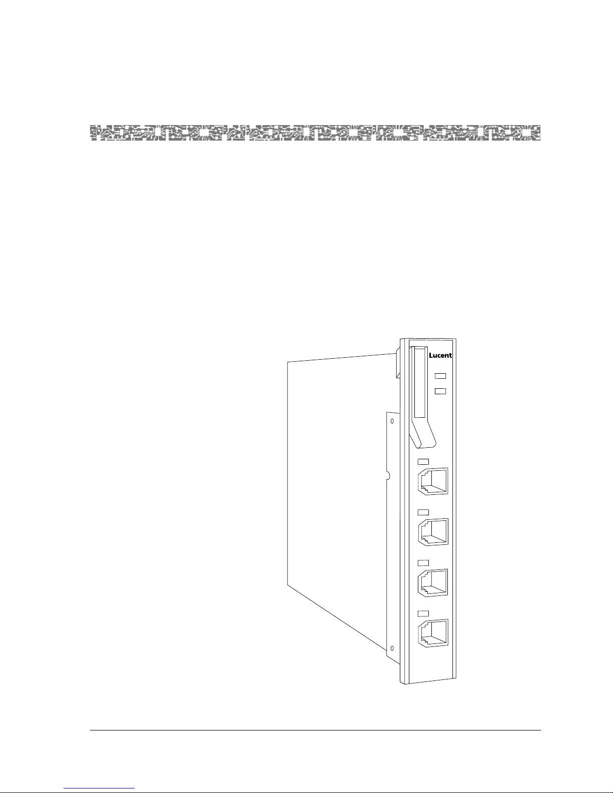
The 4-Port Voice 2-W ire Office module has three types of LED indicators:
ACTIVE, FAIL, and LOS (loss of signal). Each port has a LOS LED on the
faceplate. The LED turns on when the port goes off-hook. It also turns on and
off in synchonization with an incoming ringing signal to the port.
2 Module Description
FAIL
1
ACTIVE
Figure 2-1. 4-Port Voice 2-Wire Office Module
VOICE
2WO
1
2
3
4
PacketStar® 4-Port Voice 2-Wire Office Module User Guide, Issue1 Release7.0
255-700-186 2-1
Page 24

Chapter 2 Module Description
4-Port Voice 2-Wire Office Module
4-Port Voice 2-Wire Office Module
This module is typically configured with an 8-Port Voice 2-Wire Station
module via a PVC connection to enable a foreign exchange (FXO) voice
service to be transmitted across an ATM network. With FXO service, the
voice switch provides dial tone, ringing, and digit translation, which are not
provided by the ATM network.
Module Placement Requirements
Note: Do no place the 4-Port Voice 2-Wire Office module module in the
PSAX 4500 chassis; the module is not supported.
In all other PSAX chassis, you may install the module in any slot intended to
contain I/O or server modules. In typical applications, this module is used
with the 8-Port 2-Wire Station module, (see the appropriate module guide).
Hardware Features
The 4-Port Voice 2-Wire Office module supports these hardware features:
• Number of ports: 4
• Connector type: RJ-11
• Ringing frequency: 20 Hz
• Termination impedance: 600 Ohms
• Signaling: dual tone multi-frequency (DTMF)
• Supervision: loop start
General Hardware Specifications
Table 2-1 shows the general physical and environmental hardware
specifications for the PSAX Multiservice Media Gateway I/O and server
modules.
Table 2-1. Physical Hardware Specifications for the I/O and the Server Modules
Specification Description
Dimensions:
• Height:
•Width:
• Depth:
Weight: 0.45 kg (1.0 lb.)
15.74 cm (6.2 in.)
2.41 cm (0.95 in.)
24.13 cm (9.5 in.)
PacketStar® 4-Port Voice 2-Wire Office Module User Guide, Issue1 Release7.0
2-2 255-700-186
Page 25

Chapter 2 Module Description
Chassis Speed, Power Consumption, and Memory Allocation
Table 2-1. Physical Hardware Specifications for the I/O and the Server Modules
Specification Description
Operating temperature: 0° to 50° C (32° to 122° F)
Operating relative humidity: 40 to 60%, optimum;
up to 95%, noncondensing
Storage temperature: -20° to 70° C (-4° to 158° F)
Chassis Speed, Power Consumption, and Memory Allocation
Chassis speed, power consumption, and memory allocation specifications for
the 4-Port Voice 2-Wire Office module are described in Table 2-2.
Table 2-2. Chassis Speed, Power Consumption, and Memory Allocation Specifications
Maximum
Input
1
Buffer
Output
Buffer
Chassis
Speed
Speed
2
Module
4-Port Voice 2-Wire
Total
Amount of
SDRAM
8MB 4MB N/A N/A Low
Module
Program and
Data Space
Office (VOICE 2WO)
1
The I/O buffers carry 16,384 cells per megabyte for all Multiservice Media Gateway modules except the Voice 2-Wire
Office module, the Voice 2-Wire Station module, and the DSP2x Voice Server modules, which have no cells carried
on the I/O buffers.
2
This column relates only to the performance of the module in the PSAX 4500 chassis. All modules operate in a low-
speed mode in all other PSAX chassis. The speed rel ates to the performance of the data being passed through the
midplane of the chassis.
LED Indicators
Table 2-3 describes how the light-emitting diode (LED) indicators on the 4Port Voice 2-Wire Office module faceplates respond to different module
conditions. These LEDs indicate if the module has been installed properly.
Before you configure the 4-Port Voice 2-Wire Office module, you must
ensure that it is properly initialized according to the information provided in
Table 2-3.
Power Con-
sumption
14 W
PacketStar® 4-Port Voice 2-Wire Office Module User Guide, Issue1 Release7.0
255-700-186 2-3
Page 26

Chapter 2 Module Description
LED Indicators
Table 2-3. LED Indicators for the 4-Port Voice 2-Wire Office Module
Module
Status
LED
FAIL
(red)
ACTIVE
(green)
Line Status LOS
(green)
1
Note: After power is initially applied to the system and the system boot is
complete, the FAIL and ACTIVE LEDs indicate whether the module has no
configured ports (red), or one or more configured ports (green).
2
Note: This module does not have this label next to the LED indicator on
the faceplate.
Power-On
Lights
briefly
Lights
briefly
Each lights
2
briefly
Initial
1
1
No
Configured
Ports
One or More
Configured
Ports
Not lit Lights only
when the
module is
not functioning
Not lit Lights only
when the
module is
functioning properly
Not
Applicable
Not
Applicable
No Cable on
Port
Not
Applicable
Not
Applicable
Cable on
Port
Not
Applicable
Not
Applicable
Not lighted Flashing
green LED
indicates
the line is
ringing.
Solid green
LED indicates the
line is offhook (in
use) or
busy.
Unilluminated LED
indicates
the line is
on-hook
(not in
use).
Note: Shielded RJ-11 to RJ-11, straight through cables are needed with
PacketStar® 4-Port Voice 2-Wire Office Module User Guide, Issue1 Release7.0
2-4 255-700-186
the 4-Port Voice 2-Wire Office module.
Page 27

3 Configuring Ports and Channels
Using the Console Interface
Overview of This Chapter
This chapter describes how to set the values for the port and channel
configuration for the 4-Port Voice 2-Wire Office module using the PSAX
Multiservice Media Gateway system console interface.
Before You Begin
Be sure to complete the following actions first before configuring the 4-Port
Voice 2-Wire Office module:
• Configure your basic system (see "Configuring the System for Your Site"
in Chapter 4 of the appropriate PacketStar
Gateway user guide)
®
PSAX Multiservice Media
• Configure the Stratum 3–4 mod ule (see "Configuring the Stratum 3–4
Module" in Chapter 4 of the appropriate PacketStar
Media Gateway user guide)
When configuring the 4-Port Voice 2-Wire Office module using the PSAX
Multiservice Media Gateway console, display-only fields are displayed with
brackets.
The status line at the bottom of the console window gives instructions for the
field currently selected, and displays trap messages (see the appendix of your
chassis user guide for a table of defined trap messages).
!
CAUTION:
When using a DSP2A, DSP2B, DSP2C, or DSP2D Voice Server module and
an Enhanced DS1 or E1 module with a PBX and/or key telephone system,
the Multiservice Media Gateway system and your equipment should use
a common chassis ground connection to avoid ground current loops,
which could affect voice quality.
Configuring the Module
T o configure the 4-Port V oice 2-Wire Office module ports, follow the steps in
the following procedure.
®
PSAX Multiservice
PacketStar® 4-Port Voice 2-Wire Office Module User Guide, Issue1 Release7.0
255-700-186 3-1
Page 28
Chapter 3 Configuring Ports and Channels Using the Console Interface
Configuring the Module
Configuring the Ports
Begin
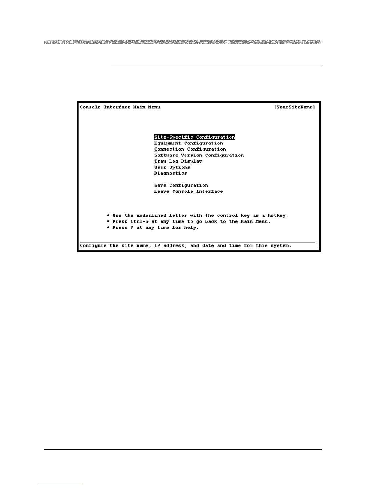
1 On the Console Interface Main Menu window (see Figure 3-1), select
the Equipment Configuration option and press Enter.
Figure 3-1. Console Interface Main Menu (Equipment Configuration Selected)
The Equipment Configuration window (see Figure 3-2 and Figure 3-3)
is displayed.
PacketStar® 4-Port Voice 2-Wire Office Module User Guide, Issue1 Release7.0
3-2 255-700-186
Page 29
Chapter 3 Configuring Ports and Channels Using the Console Interface
Configuring the Module
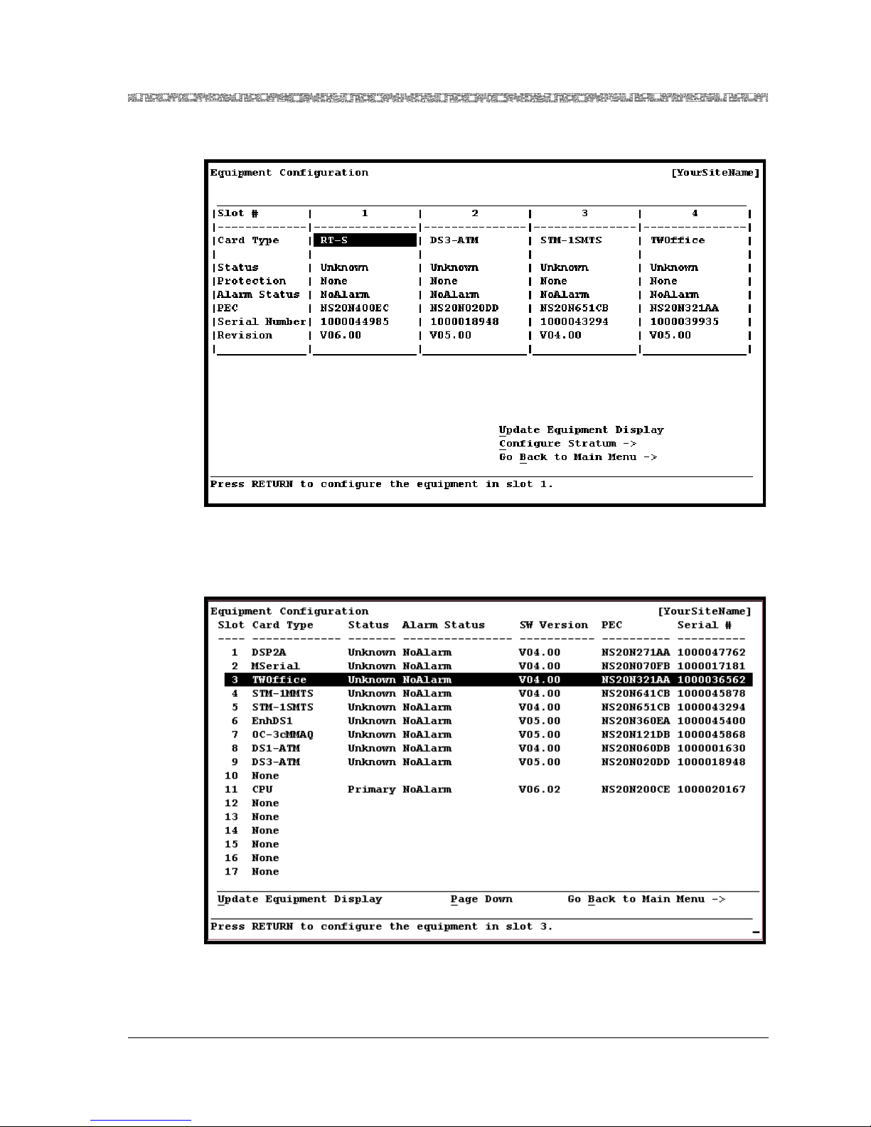
Figure 3-2. Equipment Configuration Windo w (As Displayed o n the PSAX 20
and AC 60 Console)
Figure 3-3. Equipment Configuration Window (As Displa yed on the PSAX 1250,
PacketStar® 4-Port Voice 2-Wire Office Module User Guide, Issue1 Release7.0
255-700-186 3-3
PSAX 2300, and PSAX 4500 Console)
Page 30
Chapter 3 Configuring Ports and Channels Using the Console Interface
Configuring the Module
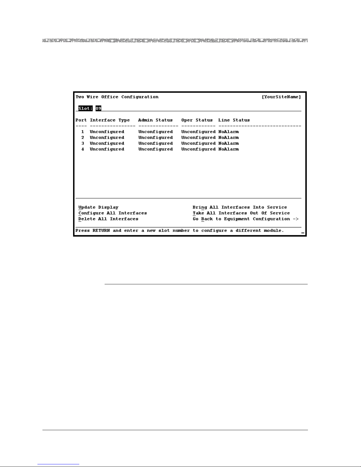
2 On the Equipment Configuration window, select the 4-Port Voice 2-
Wire Office module and press Enter.
The Two Wire Office Configuration window is displayed (see
Figure 3-4).
Figure 3-4. Two Wire Office Configuration Window
Commands The commands in this window have the following functions:
Command Function
• Update Display Updates the values in the fields to show the most
current configuration.
Use this command mostly to display the most
current information in the Line Status field.
• Configure All Interfaces Sets all four ports to the circuit emulation type
interface. The value CircuitEmulation is displayed in the Interface Type field, and the value
OutOfService is displayed in the Oper Status
field.
• Delete All Interfaces Deletes the configured interfaces for all four
ports. The value Unconf igured is displayed in
the Interface Type and the Oper Status fields.
Note: You must first take all interfaces out of
service (using the Take All Interfaces Out Of
Service command) before you can use this
command to delete all the configured interfaces.
PacketStar® 4-Port Voice 2-Wire Office Module User Guide, Issue1 Release7.0
3-4 255-700-186
Page 31

Chapter 3 Configuring Ports and Channels Using the Console Interface
Configuring the Module
Command Function
• Bring All Interfaces
Into Service
Brings the out-of-service configured interfaces
for all four ports to in-service status. The value
InService is displayed in the Oper Status field
for all four ports.
• Take All Interfaces Out
Of Service
Takes the in-service configured interfaces for all
four ports to out-of-service status. The value
OutOfService is displayed in the Oper Status
field for all four ports.
Note: You must use this command first before
using the Delete All Interfaces command.
• Go Back to Equipment
Configuration
→
Redisplays the Equipment Configuration window.
3 To configure the ports, do one of the following:
a. If you want to configure all four ports with the default port field
values given in Table 3-1 on page 3-7, select the Configure All
Interfaces command and press Enter.
The value CircuitEmulation is displayed in the Interface Type field, and
the value OutOfService is displayed in the Oper Status field.
b. To configure one port at a time (to set values other than the default
ones), select the line for the port you want to configure and press
Enter.
The Two Wire Office Port and Channel Configuration window (see
Figure 3-5) is display e d.
PacketStar® 4-Port Voice 2-Wire Office Module User Guide, Issue1 Release7.0
255-700-186 3-5
Page 32

Chapter 3 Configuring Ports and Channels Using the Console Interface
Configuring the Module
Figure 3-5. Two Wire Office Port and Channel Configuration Window
Commands The commands in this window have the following functions:
Command Function
• Apply Port and Channel C on figuration
• Reset Port and Channel Display
• Bring Inte rfa c e In t o Ser vice
(displayed when the [Oper
Status] field is OutOfService)
• Take Interface Out of Service
(displayed when the [Oper
Status] field is InService)
Applies the configuration field values you
set.
Resets the fields to the last set of saved
values.
Brings an out-of-service configured interface to in-service status. The value
InService is displayed in the [Oper Status]
field.
T akes an in-service configured interface to
out-of-service status. The value
OutOfService is displayed in the [Oper
Status] field.
• Configure Interface
→ Displays the Circuit Emulation Interface
Configuration window.
• Enter to Card Configura-
→
tion
Redisplays the Two Wire Office Configuration window.
PacketStar® 4-Port Voice 2-Wire Office Module User Guide, Issue1 Release7.0
3-6 255-700-186
Page 33

Chapter 3 Configuring Ports and Channels Using the Console Interface
Configuring the Module
Field Descriptions 4 Select the values for the fields on this window from the values given in
Table 3-1.
Table 3-1. Field Values for the Two Wire Office Port and Channel Configuration
Window
Field Name Values Description
Test Mode Default: Off The module is not in test mode.
QuietTime Quiet Time is useful only if the line is
not quiet enough. If the line is noisy,
the quiet time feature will help you to
determine whether the channel is
noisy. If noise is present on the line,
then the channel is defective.
Note: Do not select this value
unless the line is noisy.
F-1004Hz A 1004 Hz tone is used in troubleshoot-
ing a system where a line is seized by
bridging the tip and ring wires through
a resistance.
[Signaling Bits]
(display only)
[Dial Mode]
Ab Signaling bits method supported is AB
(two-bit signaling).
Dtmf Dual tone multi-frequency
(display only)
[Loop Detect]
LoopStart Loop detection.
(display only)
PacketStar® 4-Port Voice 2-Wire Office Module User Guide, Issue1 Release7.0
255-700-186 3-7
Page 34

Chapter 3 Configuring Ports and Channels Using the Console Interface
Configuring the Module
Table 3-1. Field Values for the Two Wire Office Port and Channel Configuration
Window
Field Name Values Description
[Line Status]
(display only)
Indicates the Line Status of the
interface. It contains loopback, failure,
received alarm and transmitted alarm
information.
See the bit map tables for the DS3
Frame Relay module under the MIB
object lineStatus in Appendix A, "SNMP
Tr ap Messages" in any PacketStar User’s
Guide.
NoAlarm
No alarm is present.
(default)
RcvFarEndLOF Far-end loss of frame.
FarEndLOF Near-end sending loss of frame
indication.
RcvAIS Far-end sending alarm indica tion si gnal.
AIS Near-end sending alarm indication
signal.
LossOfFrame Near-end loss of frame.
LossOfSignal Near-end loss of signal.
LoopbackState Near-end is looped.
T16AIS E1 TS16 AIS.
Rcv
Far-end sending TS16 LOMF.
FarEndLOMF
FarEndLOMF Near-end sending TS16 LOMF.
RcvTestCode Near-end detects a test code.
OtherFailure Any line status not defined here.
RmtLoopback Far-end loopback.
Interface Type Default:
This interface is not configured.
Unconfigured
[Oper Status]
(display only)
Circuit Emulation
Default:
Unconfigured
This interface is configured for circuit
emulation.
This channel is not operational because
the interface is not configured.
InService This channel is capable of receiving and
sending signals.
OutOfService This channel is not capable of receiving
and sending signals.
[Silence Sup-
Pvc Permanent virtual circuit (PVC).
pression]
(display only)
PacketStar® 4-Port Voice 2-Wire Office Module User Guide, Issue1 Release7.0
3-8 255-700-186
Page 35

Chapter 3 Configuring Ports and Channels Using the Console Interface
Saving the Equipment Configuration and Logging Off
Table 3-1. Field Values for the Two Wire Office Port and Channel Configuration
Window
Field Name Values Description
[Echo Cancella-
Disabled Silence suppression is disabled.
tion]
(display only)
[Voice Com-
pression]
(display only)
Disabled The echo cancellation function is dis-
abled. This function is a method for isolating and filtering unwanted signal
energy caused by echoes from the mai n
transmitted signal.
[Companding
Disabled Voice compression is disabled.
Law]
(display only)
[AAL Encapsu-
lation]
MuLawPCM The PCM coding and companding stan-
dard used in North America and Japan.
(display only)
[Silence Sup-
Aal1 ATM Adaptation Layer 1 (AAL1)
pression]
(display only)
[Service Type]
Fxo Foreign exchange office (FXO)
(display only)
5 To apply the values for the fields on this window, select the Apply Port
and Channel Configuration command and press Enter.
6 Select the Configure Interface command and press Enter.
The Circuit Emulation Interface Configuration window is displayed.
Note: For information on configuring the Circuit Emulation interface
using the AC console, see chapter 5.
7 Repeat this procedure for the remainder of the ports, as needed.
Note: Whenever needed, use the commands in the Two Wire Office
Configuration window (see Figure 3-4 on page 3-4) and on the
Two Wire Office Port and Channel Configuration window (see
Figure 3-5 on page 3-6) to manage the interfaces.
End
Saving the Equipment Configuration and Logging Off
After configuring the module ports and channels, the interface types for each
port and channel, and the connections, you must save the configuration
permanently, before you exit the current session for the PSAX system
console interface. We r ecommend that you save your configuration
PacketStar® 4-Port Voice 2-Wire Office Module User Guide, Issue1 Release7.0
255-700-186 3-9
Page 36

Chapter 3 Configuring Ports and Channels Using the Console Interface
Saving the Equipment Configuration and Logging Off
frequently, after you configure each module, and then again after
configuring the connections of each type you will have in your system.
Finally, before you exit your current session, be sure you save your
configuration for the last time. Perform the steps in the following procedure.
!
CAUTION:
If your system or location loses power or your current session ends
abnormally while you are in the process of configuring the system, and
you have not yet saved the values permanently , you will lose all unsaved
values you have applied on the various windows.
Saving the PSAX System Values
Begin
1 Press Ctrl+G while on any window to display the Console Interface
Main Menu window.
2 Select the Save Configuration command and press Enter (or press
Ctrl+A).
Wait a few seconds while the system writes the values permanently to
the Multiservice Media Gateway system database. The system displays
the following message while it is executing this command:
Saving the equipment and connection information
When the command is completed, the system displays the following
message:
T-SaveConfiguration: saveConfigurationReasonCode=AllOK
You can now safely exit the current session.
Note: In PSAX systems with redundant CPU2 modules, the backup
CPU2 module reboots every time you save the configuration on
the primary CPU2 module. This event is a function of the SVC
retention feature and the result of saving the configuration
changes you have made.
3 Select the Leave Console Interface command and press Enter.
You are now logged off the PSAX Multiservice Media Gateway system
console interface.
End
PacketStar® 4-Port Voice 2-Wire Office Module User Guide, Issue1 Release7.0
3-10 255-700-186
Page 37

4 Configuring Ports and Channels
Using the AQueView® System
Overview of This Chapter
This chapter describes how to set the values for the port and channel
configuration for the 4-Port Voice 2-Wire Office module using the AQueView
Element Management System (EMS).
Before You Begin
Be sure to complete the following actions first before configuring the 4-Port
Voice 2-Wire Office module:
• Set the values to configure your basic system (see the appropriate
• Set the values to configure the Stratum 3–4 module (see the appropriate
When configuring the 4-Port Voice 2-Wire Office module using the
AQueView
!
When using a DSP2A, DSP2B, DSP2C, or DSP2D Voice Server module and
an Enhanced DS1 or E1 module with a PBX and/or key telephone system,
the Multiservice Media Gateway system and your equipment should use
a common chassis ground connection to avoid ground current loops,
which could affect voice quality.
AQueView
AQueView
®
EMS, display-only fields are gray.
CAUTION:
®
Element Management System User Guide)
®
Element Management System User Guide)
®
Using the Right-Click Menu
You can perform various functions in the AQueView system by clicking the
right mouse button. This section describes the right-click menu options you
can use in the various windows in the AQueView system when configuring
ports and channels.
PacketStar® 4-Port Voice 2-Wire Office Module User Guide, Issue1 Release7.0
255-700-186 4-1
Page 38

Chapter 4 Configuring Ports and Channels Using the AQueView® System
Using the Right-Click Menu
Configuring Ports
and Channels
Figure 4-1. Sample Port Configuration (Displaying Right-Click Menu)
Figure 4-2. Sample Channel Configuration (Displaying Right-Click Menu)
Table 4-1. Descriptions of the Port and Channel Configuration Right-Click Menu
Options
Option Function
Configure Opens the port and channel configuration window of a
module.
Bring All Inter-
Sets all interfaces on a port administratively into service.
faces Into Service
Take All Inter-
faces Out of Ser-
Takes all interfaces on a port administratively out of service.
vice
PacketStar® 4-Port Voice 2-Wire Office Module User Guide, Issue1 Release7.0
4-2 255-700-186
Page 39

Chapter 4 Configuring Ports and Channels Using the AQueView® System
Configuring the Voice 2-Wire Office Module
Table 4-1. Descriptions of the Port and Channel Configuration Right-Click Menu
Options
Option Function
Delete All Interfaces
Channel Selection
Deletes all interfaces. All interfaces to be deleted must
be administratively out of service first.
Opens the appropriate channel configuration window
for the selected channel.
Context-Sensitive
Help
If you right-click on a field in a port and channel configuration window, a
description of that field appears (see Figure 4-3):
Figure 4-3. Sample of Context-Sensitive Help
Configuring the Voice 2-Wire Office Module
You must first configure the 4-Port Voice 2-Wire Office module before you
can set up connection provisioning.
PacketStar® 4-Port Voice 2-Wire Office Module User Guide, Issue1 Release7.0
255-700-186 4-3
(Displayed on a Port and Channel Configuration Window)
Page 40

Chapter 4 Configuring Ports and Channels Using the AQueView® System
Configuring the Voice 2-Wire Office Module
To access theport and channel configuration functions in the AQueView
system, do the following:
1. Log in to the AQueView system as a user with Administrator or
Configurator access privileges.
2. From the Device List or the Open Device window (press Ctrl+D or
Ctrl+O), open the PSAX device that contains the module on which you
want to configure a port or channel. The Front Panel view and Device
Tree for that PSAX device will appear (see Figure 4-4).
Figure 4-4. Provisioning Window (Displaying a Typical Setup)
Configuring the Module
To configure the ports of a 4-Port Voice 2-Wire Office module, perform the
steps in the following procedure.
PacketStar® 4-Port Voice 2-Wire Office Module User Guide, Issue1 Release7.0
4-4 255-700-186
Page 41

Chapter 4 Configuring Ports and Channels Using the AQueView® System
Configuring the Voice 2-Wire Office Module
Configuring the Ports
Begin
1 Do one of the following to open the Port and Channel Configuration
window:
~ In the Front Panel, click the left button twice on the port to be
configured or displayed (see Figure 4-5).
~ In the Front Panel, double-click the right button on the port and a
menu appears. Click Configure in the menu that appears.
~ In the Device Tree, double-click the desired port symbol or identifier
with the left mouse button.
~ In the Device Tree, select a port then click the right mouse button on
the Device Tree and a menu appears. Click Configure.
Figure 4-5. Front Panel View of the Voice 2-Wire Office Module
PacketStar® 4-Port Voice 2-Wire Office Module User Guide, Issue1 Release7.0
255-700-186 4-5
The 2-Wire Office Port and Channel window displays (see Figure 4-6).
This window contains the following:
~ The Port Configuration page allows you to do the following:
• Select and apply port settings
• View port statistics, which display line errors and coding violations
• View line status
~ The Channel Configuration page allows you to do the following:
• Select and apply an interface
Page 42

Chapter 4 Configuring Ports and Channels Using the AQueView® System
Configuring the Voice 2-Wire Office Module
• Open the Interface Configuration window to configure the
interface
• Channel Configuration panel for entering the interface type and
displaying the operational status, connection and service type,
silence suppression, echo cancellation and voice suppression, voice
compression, companding law, and AAL Encapsulation. Once the
interface is selected and applied, interface parameters can be
entered into the Interface Parameters window.
Note: All interfaces must be out of service before changes can be made
to the port settings; otherwise, the Apply button will appear to be
ghosted.
Figure 4-6. 2-Wire Office Port and Channel Configuration Window
Buttons The buttons on this window have the following functions:
PacketStar® 4-Port Voice 2-Wire Office Module User Guide, Issue1 Release7.0
4-6 255-700-186
Button Function
• Close Closes this window.
• Apply Applies the configuration field value you set.
• Reset Resets the fields to the last set of applied values.
Page 43

Chapter 4 Configuring Ports and Channels Using the AQueView® System
Configuring the Voice 2-Wire Office Module
Field Descriptions 2 In the Port Configuration window, select the appropriate settings shown
in Table 4-2.
Table 4-2. Field Values for the Two Wire Office Port and Channel Configuration
Window
Field Name Values Description
Test Mode Default: Off The module is not in test mode.
QuietTime Quiet Time is useful only if the line is
not quiet enough. If the line is noisy,
the quiet time feature will help you to
determine whether the channel is
noisy. If noise is present on the line,
then the channel is defective.
Note: Do not select this value
unless the line is noisy.
F-1004Hz A 1004 Hz tone is used in troubleshoot-
ing a system where a line is seized by
bridging the tip and ring wires through
a resistance.
Signaling Bits
(display only)
Dial Mode
Ab Signaling bits method supported is AB
(two-bit signaling).
Dtmf Dual tone multi-frequency
(display only)
Loop Detect
LoopStart Loop detection.
(display only)
PacketStar® 4-Port Voice 2-Wire Office Module User Guide, Issue1 Release7.0
255-700-186 4-7
Page 44

Chapter 4 Configuring Ports and Channels Using the AQueView® System
Configuring the Voice 2-Wire Office Module
Table 4-2. Field Values for the Two Wire Office Port and Channel Configuration
Window
Field Name Values Description
Line Status
(display only)
Indicates the Line Status of the
interface. It contains loopback, failure,
received alarm and transmitted alarm
information.
See the bit map tables for the DS3
Frame Relay module under the MIB
object lineStatus in Appendix A, "SNMP
Tr ap Messages" in any PacketStar User’s
Guide.
NoAlarm
No alarm is present.
(default)
RcvFarEndLOF Far-end loss of frame.
FarEndLOF Near-end sending loss of frame
indication.
RcvAIS Far-end sending alarm indica tion si gnal.
AIS Near-end sending alarm indication
signal.
LossOfFrame Near-end loss of frame.
LossOfSignal Near-end loss of signal.
LoopbackState Near-end is looped.
T16AIS E1 TS16 AIS.
Rcv
Far-end sending TS16 LOMF.
FarEndLOMF
FarEndLOMF Near-end sending TS16 LOMF.
RcvTestCode Near-end detects a test code.
OtherFailure Any line status not defined here.
RmtLoopback Far-end loopback.
Interface Type Default:
This interface is not configured.
Unconfigured
Connection
Type
Circuit Emulation
Pvc Permanent virtual circuit (PVC).
Svc Switched virtual circuit (SVC).
This interface is configured for circuit
emulation.
PacketStar® 4-Port Voice 2-Wire Office Module User Guide, Issue1 Release7.0
4-8 255-700-186
Page 45

Chapter 4 Configuring Ports and Channels Using the AQueView® System
Configuring the Voice 2-Wire Office Module
Table 4-2. Field Values for the Two Wire Office Port and Channel Configuration
Window
Field Name Values Description
Service Type Plar Private line automatic ringdown. Use
this only for PVC connections.
Fxs Foreign exchange subscriber (FXS).
Use this only for PVC connections.
Caller ID and flashhook signalling support under FXS.
S-signaling Select this value for SVC connections
only.
Silence Sup-
Pvc Permanent virtual circuit (PVC).
pression
(display only)
Echo Cancella-
Disabled Silence suppression is disabled.
tion
(display only)
Voice Compres-
sion
(display only)
Disabled The echo cancellation function is dis-
abled. This function is a method for isolating and filtering unwanted signal
energy caused by echoes from the mai n
transmitted signal.
Companding
Disabled Voice compression is disabled.
Law
(display only)
AAL Encapsula-
tion
MuLawPCM The PCM coding and companding stan-
dard used in North America and Japan.
(display only)
Silence Sup-
Aal1 ATM Adaptation Layer 1 (AAL1)
pression
(display only)
3 Click Apply.
End
Copying a Port Configuration
The Copy button on the Port and Channel Configurat ion window of each I/O
module enables you to copy a port configuration to a range of ports. To copy
a port configuration to a range of ports, perform the steps in the following
procedure from the appropriate Port and Channel Configuration window.
PacketStar® 4-Port Voice 2-Wire Office Module User Guide, Issue1 Release7.0
255-700-186 4-9
Page 46

Chapter 4 Configuring Ports and Channels Using the AQueView® System
Configuring the Voice 2-Wire Office Module
Copying a Port Configuration to Multiple Ports
Begin
1 On the Port Configuration page, click Copy.
The Copy Port Configuration window appears with the slot and port of
the module you selected in the Start At: and Stop At: panels (see
Figure 4-7).
Figure 4-7. Sample Copy Port Configuration Window
Buttons The buttons in this window have the following functions:
Button Function
• Close Closes this window.
• Copy Copies this interface to a range of channels.
2 Select the range of slots and ports to which you wish the port
configuration to be copied.
3 To copy the interface configuration of this module, click the box beside
Copy interface configuration.
4 To overwrite the existing inter face configuratio n of the destinat ion ports,
click the box beside Overwrite configured interfaces (this option is only
available if Copy interface configuration is selected).
Note: The Overwrite configured interfaces option is ghosted until you
click the box beside Copy interface configuration.
5 Click Copy.
The port configuration is copied to the range of ports you selected.
End
Channel
Configuration
PacketStar® 4-Port Voice 2-Wire Office Module User Guide, Issue1 Release7.0
4-10 255-700-186
To configure the channels of a 4-Port Voice 2-Wire Office module, perform
the steps in the following procedure.
Page 47

Chapter 4 Configuring Ports and Channels Using the AQueView® System
Configuring the Voice 2-Wire Office Module
Configuring the Channels
Begin
1 Click the Channel Configuration tab.
The Channel Configurat io n page appe a rs (see Figure 4-8).
Figure 4-8. Channel Configuration Page
Buttons The buttons on this window have the following functions:
Button Function
• Apply to Selected Applies the configuration field value you set.
• Close Closes this window.
2 In the Channel Configuration page, either click the arrow in the
Interface Type field (in the middle of the window), or double-click the
channel in the Interface Type field.
3 Select CircuitEmulation.
4 For information on configuring this interface, see Chapter 6,
"Configuring the Interface Using the AQueView System"
5 Click Apply to Selected.
PacketStar® 4-Port Voice 2-Wire Office Module User Guide, Issue1 Release7.0
255-700-186 4-11
Page 48

Chapter 4 Configuring Ports and Channels Using the AQueView® System
Configuring the Voice 2-Wire Office Module
Note: You can double-click on a channel in the Interface Type field to
select a new interface only when an interface is not currently
selected for that channel. If an interface is applied for a channel
and you double-click on it in the Interface Type field, the
Interface Configuration window appears.
6 Click the right mouse button in the list in the Channel Configuration
window and a menu appears. Click Bring Selected Into Service.
7If you want to configure the interface, do one of the following:
~ Double-click the left mouse button on the channel for which you want
to configure the interface.
~ Click the right mouse button on the channel for which you want to
configure the interface and a menu appears. Select Configure in the
menu.
The Circuit Emulation Interface Configuration window displays. See
Chapter 6 for instructions on configuring this interface.
8 Repeat Step 1–Step 6 to configure more channels.
9 In the Channel Configuration page, click Close.
End
PacketStar® 4-Port Voice 2-Wire Office Module User Guide, Issue1 Release7.0
4-12 255-700-186
Page 49

5 Configuring the Interfaces Using
Overview of This Chapter
This chapter provides instructions for configuring the circuit emulation
interface type for the 4-Port Voice 2-Wire Office module using the
Multiservice Media Gateway console.
For a matrix of interface types by PSAX I/O module types, see the “Interface
Types by I/O Module Types Table” in the Reference Table appendix of this
user guide.
Circuit Emulation Interface
This section provides instructions for configuring an I/O module for the
Circuit Emulation interface.
the Console Interface
Configuring the Circuit Emulation Interface
Begin
1 When you select the value CircuitEmulation as the interface type on the
Port and Channel configuration window, the Circuit Emulation
Interface Configuration window (see Figure 5-1) is displayed.
PacketStar® 4-Port Voice 2-Wire Office Module User Guide, Issue1 Release7.0
255-700-186 5-1
Page 50

Chapter 5 Configuring the Interfaces Using the Console Interface
Circuit Emulation Interface
Figure 5-1. Circuit Emulation Interface Configuration Window
Commands The commands in this window have the following functions:
Command Function
• Bring Int e rfa ce In t o
Service (displays when
the [Admin Status]
field is OutOfService)
Brings an out-of-service configured interface to
in-service status. The value InService displays in
the [Admin Status] field.
You mus t first configure the inte rface before you
can use this command.
• Take Interface Out of
Service (displays when
the [Admin Status]
field is InService)
Takes an in-service configured interface to outof-service status. The value OutOfService dis-
plays in the [Admin Status] field.
Note: You must use this command first before
using the Delete Interface and Return
command.
• Add Interface Applies the configuration field values you set.
PacketStar® 4-Port Voice 2-Wire Office Module User Guide, Issue1 Release7.0
5-2 255-700-186
Page 51

Chapter 5 Configuring the Interfaces Using the Console Interface
Command Function
• Delete Interface and
Return
Circuit Emulation Interface
Deletes an out-of-service interface and redisplays the Port and Channel Configuration window for the module you are configuring.
Note: You must first take interface out of
service (using the T ake Interface Out of Service
command) before you can use this command.
• Go Back to Port Configuration
Redisplays the Port and Channel Configuration
window of the module you are configuring.
Field Descriptions 2 Select the values for the fields on this window from the values given in
Table 5-1.
Table 5-1. Field Values for the Circuit Emulation Interface Configuration Window
Field Names Values Description
CAS Idle abcd
Pattern
CAS Busy abcd
Pattern
Alarm Data Pattern
TC Final abcd
Bits
Default: 0
Range: 0–15
Default: 15
Range: 0–15
Default: 127
(idle pattern)
Range: 0–255
Default:
CasBusy
Signaling abcd bit pattern for first 2.5
seconds.
Signaling abcd bit pattern after 2.5 seconds.
The data pattern to be transmitted out
on a circuit emulation port, if no user
data is available for the transmission.
Bit pattern to be transmitted after 2.5
seconds.
CasIdle Bit pattern to be transmitted after 2.5
seconds.
PacketStar® 4-Port Voice 2-Wire Office Module User Guide, Issue1 Release7.0
255-700-186 5-3
Page 52

Chapter 5 Configuring the Interfaces Using the Console Interface
Circuit Emulation Interface
Table 5-1. Field Values for the Circuit Emulation Interface Configuration Window
Field Names Values Description
DownStream
Interworking
Default:
TrunkCond
Trunk conditioning will be done with
ATM network. The PSAX system will
generate an idle data pattern in the
payload of ATM cells to send a signal to
indicate a connection failure.
Unsupp No interworking will be done with ATM
network. The PSAX system will not
send a signal to indicate a connection
failure. Do not choose this value if you
want to enable trunk conditioning.
OAM OAM interworking will be done with
AT M netw ork.
The PSAX system will use ATM OAM
cells to send a signal to indicate a connection failure. You can use this value
if all the ATM switches along the connection support ATM OAM cells.
You must use this value if you selected
Unframed1s in the UpStrmIntrworking field on the Port and Channel Con-
figuration window of the module you
are configuring. The PSAX system does
not support upstream interworking of
unframed 1s with a downstream setting
of trunk conditioning.
Operational Status
(display only)
InService Indicates that the interface is opera-
tional.
OutOfService Indicates that the interface is not opera-
tional.
Administrative
Status
(display only)
InService Indicates that the interface is in service.
OutOfService Indicates that the interface is not in ser-
vice.
3 To bring the interface to in-service status, select the Bring Interface Into
Service command and press Enter.
The value InService is displayed in the [Operational Status] field.
End
If you need to change the interface configuration values at any time after the
interface has been brought into service, you must take the interface out of
PacketStar® 4-Port Voice 2-Wire Office Module User Guide, Issue1 Release7.0
5-4 255-700-186
Page 53

Chapter 5 Configuring the Interfaces Using the Console Interface
Circuit Emulation Interface
service, delete the current interface, and then re-create another interface
after configuring the desired values.
Note: The interface must have in-service status in order for the PVCs
and SVCs you establish on this interface to work.
Taking the Interface
Out of Service
Deleting the
Interface
To take the interface out of service, perform the steps in the following
procedure.
Steps to Take the Interace Out of Service
Begin
1 Select the Take Interface Out Of Service command and press Enter.
2 Press the Y key (to indicate yes) to continue.
The interface is taken out of service.
!
CAUTION:
If you delete the interface, the current permanent virtual circuits (PVCs)
and switched virtual circuits (SVCs) using this interface will be deleted
from the system.
Note: To delete the interface, the interface must be out-of-service.
To delete the interface, perform the steps in the following procedure.
Steps to Delete the Interface
Begin
1 To delete an interface from the Interface Configuration window, select
the Delete Interface and Return command and press Enter. Go to
Step 4.
2 To delete an interface from the Port and Channel Configuration window,
select Unconfigured in the Interface Type field on the Port and Channel
Configuration window.
3 Select the Apply Configuration command.
The following message is displayed:
Taking the interface down will cause all SVCs to be lost.
Continue? (y/n)
4 Press the Y key (to indicate yes) to continue.
Are you sure you want to delete this interface?
5 Press Enter to delete the interface.
6 To re-create the interface, repeat steps in the procedure, "Setting the
Values for the Interface."
PacketStar® 4-Port Voice 2-Wire Office Module User Guide, Issue1 Release7.0
255-700-186 5-5
Page 54

Chapter 5 Configuring the Interfaces Using the Console Interface
Circuit Emulation Interface
Note: The interface must have in-service status in order for the PVCs
and SVCs you establish on this interface to work.
End
PacketStar® 4-Port Voice 2-Wire Office Module User Guide, Issue1 Release7.0
5-6 255-700-186
Page 55

6 Configuring Interfaces Using the
AQueView® System
Chapter Overview
This chapter provides instructions for configuring the circuit emulation
interface type for the 4-Port Voice 2-Wire Office module using the
AQueView
Errors Applying Interfaces to Ports
An error can occur when you apply an interface to a port or channel. (See
the appendix, “SNMP Trap Messages,” for more information about the SNMP
traps related to interface errors).
• Entering values into fields that are outside of the configurable range of
• Attempting to configure an interface for a port or channel that has
®
element management system.
values
already been configured
• Attempting to configure an interface that is already in service (must be
out of service to be configured or change field values)
The Circuit Emulation Interface
This section provides instructions for configuring an I/O module for the
Circuit Emulation interface.
Setting Up the Interface
Begin
When you select CircuitEmulation as the interface type in the Channel
Configuration page, the Circuit Emulation Interface Configuration window
appears (see Figure 6-1).
PacketStar® 4-Port Voice 2-Wire Office Module User Guide, Issue1 Release7.0
255-700-186 6-1
Page 56

Chapter 6 Configuring Interfaces Using the AQueView® System
The Circuit Emul ation Interface
Figure 6-1. Circuit Emulation Interface Configuration Window
Buttons 1 Select the values for the buttoms on this window from the following
table:
Button Function
• Calculate Navis NSAP
Address
Note: This button appears only when you configure user propertie s to includ e the Navis NSAP
format. For more information, see the appropri-
®
ate AQueView
Element Management System User
Guide.
Automatically calculates the local NSAP address,
and populates the NSAP address in the NSAP
Address (Hex) field using the Navis algorithm
for the slot, port, and channel selected in the
fields on the bottom right panel.
• Bring Into Service (displays when the Admin-
istrative Status field is
OutOfService)
Brings an out-of-service configured interface to
in-service status. The value InService displays in
the Administrative Status field.
Note: You must first configure the interface
before you can use this button.
PacketStar® 4-Port Voice 2-Wire Office Module User Guide, Issue1 Release7.0
6-2 255-700-186
Page 57

Chapter 6 Configuring Interfaces Using the AQueView® System
The Circuit Emulation Interface
Button Function
• Take Out of Service
(displays when the
Administrative Status
field is InService)
Takes an in-service configured interface to outof-service status. The value OutOfService displays in the Administrative Status field.
Note: You must use this button first before
using the Delete button.
• Delete Deletes an out-of-service interface and redis-
plays the Port and Channel Configuration window for the module you are configuring.
Note: You must first take interface out of
service (using the Take Out of Service button)
before you can use this button.
• Copy Copies this interface to a range of slots, ports,
and channels.
• Close Closes this window.
• Apply Applies the configuration field value you set.
• Reset Resets the fields to the last set of applied values.
Circuit Emulation
Interface Values
Table 6-1. Field Values for the Circuit Emulation Interface Configuration Window
Field Names Values Description
Interface Type Circuit Emulation displays as the inter-
face type.
Signaling
(displays only
when configuring circuit emulation on the
Multi-Serial,
Enhanced DS1,
and Channel-
Default: CCS
Clear Channel
signaling
CAS (channelassociated signaling)
Clear Channel Signaling—ABCD signal-
ing bits not used.
Channel Associated Signaling—
signaling bit tra nsport based on ATM
Forum stardard for ABCD signaling bits.
ISDN requires the use of the who le
port. Will not function with CAS.
ized DS3 mod-
ules)
Speed Adapta-
tion
Default:
Enabled
Refers to robbed-bit signaling in circuit
emulation interfaces.
Disabled Refers to robbed-bit signaling in circuit
emulation interfaces.
CAS Idle abcd
Pattern
CAS Busy abcd
Pattern
Default: 0
Range: 0–15
Default: 15
Range: 0–15
Signaling abcd bit pattern for first 2.5
seconds.
Signaling abcd bit pattern after 2.5 sec-
onds.
PacketStar® 4-Port Voice 2-Wire Office Module User Guide, Issue1 Release7.0
255-700-186 6-3
Page 58

Chapter 6 Configuring Interfaces Using the AQueView® System
The Circuit Emul ation Interface
Table 6-1. Field Values for the Circuit Emulation Interface Configuration Window
Field Names Values Description
Alarm Data Pattern
TC Final abcd
Bits
Default: 127
(idle pattern)
Range: 0–255
Default:
CasBusy
The data pattern to be transmitted out
on a circuit emulation port, if no user
data is available for the transmission.
Bit pattern to be transmitted after 2.5
seconds.
CasIdle Bit pattern to be transmitted after 2.5
seconds.
DownStream
Interworking
Default:
TrunkCond
Trunk conditioning will be done with
ATM network. The PSAX system will
generate an idle data pattern in the
payload of ATM cells to send a signal to
indicate a connection failure.
Unsupp No interworking will be done with ATM
network. The PSAX system will not
send a signal to indicate a connection
failure. Do not choose this value if you
want to enable trunk conditioning.
OAM OAM interworking will be done with
AT M netw ork.
The PSAX system will use ATM OAM
cells to send a signal to indicate a connection failure. You can use this value
if all the ATM switches along the connection support ATM OAM cells.
You must use this value if you selected
Unframed1s in the UpStrmIntrworking field on the Port and Channel Con-
figuration window of the module you
are configuring. The PSAX system does
not support upstream interworking of
unframed 1s with a downstream setting
of trunk conditioning.
Operational Status
(display only)
InService Indicates that the interface is opera-
tional.
OutOfService Indicates that the interface is not opera-
tional.
Administrative
Status
(display only)
Local NSAP
Address (Hex)
InService Indicates that the interface is in service.
OutOfService Indicates that the interface is not in ser-
vice.
The ATM NSAP address of the local end
of the connection, in hexidecimal notation. Enter the NSAP address of the
local ATM interface.
PacketStar® 4-Port Voice 2-Wire Office Module User Guide, Issue1 Release7.0
6-4 255-700-186
Page 59

Chapter 6 Configuring Interfaces Using the AQueView® System
The Circuit Emulation Interface
Note: Step 2 through Step 4 are optional. If you do not want to add or
retrieve an NSAP address, skip to Step 5.
If an NSAP address exists in the NSAP address database for a given device,
the local NSAP address automatically retrieved and displayed on the Interface
Configuration window. You may choose to add an NSAP address for a slot,
port, and channel in the NSAP address database and retrieve it by clicking
Retrieve from NSAP database.
2 To add or retrieve an NSAP address, enter a valid NSAP address in the
Local NSAP Address (Hex) field and click Retrieve from NSAP
database.
If the value entered in the Local NSAP Address (Hex) field is valid, the
field becomes ghosted. The Select NSAP window appears (see the
following figure).
Figure 6-2. Select NSAP Window
Buttons The buttons in this window have the following functions:
• Retrieve Enters the NSAP address for a device that is selecte d on the
• Add Adds a new slot, port, channel, NSAP address mapping
• Save Stores any modifications to the NSAP address database.
• Close Closes this window.
PacketStar® 4-Port Voice 2-Wire Office Module User Guide, Issue1 Release7.0
255-700-186 6-5
Button Function
Select Remote NSAP window into the Remote NSAP
Address field of the Interface Configuration window.
entry for the specified device.
Page 60

Chapter 6 Configuring Interfaces Using the AQueView® System
The Circuit Emul ation Interface
You can populate the Slot, Port, Cha nnel, an d NSAP Address fields for
an existing device, or add a new entry, and click Add.
3 To display the NSAP addresses previously configured for a PSAX device,
either select a remote device from the pull-down menu, or type the IP
address of the remote device in the Remote Switch IP field.
The list of NSAP addresses previously configured for that PSAX device is
displayed in the table.
4 Select the desired entry (slot, port, channel, and NSAP address) and click
Retrieve.
The Local NSAP Address (Hex) field becomes populated in the window.
Note: If the desired remote device does not appear in the Remote Switch
IP pull-down menu, do the following:
a. Highlight the Remote Switch IP field and enter the IP address that
corresponds to the PSAX device you want to include.
b. Type the desired values into the Slot, Port, and Channel fields and
c. Click Add.
The AQueView
®
system adds this information to the database file.
Note: If you want to include a new entry for an existing device already
in the database, select the device from the pull-down menu in the
Remote Switch IP field, and type the desired values into the Slot,
Port, and Channel fields and click Add. The AQueView
adds this entry to the database file.
Note: If you add database entries through the AQueView
these database changes to the text editor file by using the main
AQueView Menu Bar. Click View > NSAP Database > Save.
5 To apply the interface configuration values, click Apply.
Copying an Interface Configuration
The Copy button on each Interface Configuration window enables you to
copy an interface configuration to a range of channels. To copy an interface
configuration to a range of channels, perform the steps in the following
procedure from the appropriate Interface Configuration window.
Copying an Interface Configuration to Multiple Channels
Begin
1 In the Interface Configuration window, click Copy.
The Copy Interface Configuration window appears with the slot, port,
and channel of the interface you selected in the Start At: and Stop At:
panels (see figure below).
®
system
®
system, save
PacketStar® 4-Port Voice 2-Wire Office Module User Guide, Issue1 Release7.0
6-6 255-700-186
Page 61

Chapter 6 Configuring Interfaces Using the AQueView® System
The Circuit Emulation Interface
Figure 6-3. Sample Copy Interface Configuration Window
Buttons The buttons in this window have the following functions:
Button Function
• Close Closes this window.
• Copy Copies this interface to a range of slots,
ports, and channels.
2 Select the range of channels to which you wish the interface
configuration to be copied in the Slot, Port, and Channel fields.
3 To overwrite the pre-existing interface configuration, click the box
beside Overwrite configured interfaces.
4 Click Copy.
The interface configuration is copied to the range of channels you
selected.
5 Click Close.
End
PacketStar® 4-Port Voice 2-Wire Office Module User Guide, Issue1 Release7.0
255-700-186 6-7
Page 62

Chapter 6 Configuring Interfaces Using the AQueView® System
The Circuit Emul ation Interface
PacketStar® 4-Port Voice 2-Wire Office Module User Guide, Issue1 Release7.0
6-8 255-700-186
Page 63

7 Provisioning Connections Using the
Console Interface
Overview of This Chapter
This chapter describes how to use the Access Concentrator console to set up
permanent virtual circuit (PVC) and soft permanent virtual circuit (SPVC)
connections in PSAX devices for service provisioning, and how to view
statistics data for billing and performance monitoring. This chapter contains
instructions for making the following types of connections:
• PVC connections:
~ Circuit Emulation-to ATM virtual channel connection (VCC)
~ Circuit Emulation-to Circuit Emulation
• SPVC connections:
~ Circuit Emulation-to-ATM VCC
Before you provision connections for the modules, you must have first
completed the following tasks:
• Set the configuration values for one or more ports on the Voice 2-Wire
Office module
• Set the configuration values for the various types of interfaces on the
Voice 2-Wire Office module
Data Flow in PVCs
PVCs consist of connections between ports on the various Access
Concentrator I/O modules. When setting up some types of connections, you
can set up data traffic to flow in several ways, depending on the type of
connection as follows:
• Duplex
• Simplex
Before you can provision connections, you must select an interface type
value other than Unconfigured in the Interface Type field on the Two Wire
Office Port and Channel Configuration window. See the Reference Table
appendix in this guide for a matrix of module and interface types.
Data flows in two directions between the two connection points
(interface side A and interface side B).
Data flows in only one direction, from side A to side B, or from side B to
side A.
PacketStar® 4-Port Voice 2-Wire Office Module User Guide, Issue1 Release7.0
255-700-186 7-1
Page 64

Chapter 7 Provisioning Connections Using the Console Interface
Provisioning PVC Connections
Provisioning PVC Connections
Accessing the Connection Configuration Menu
Begin
1 Log onto the PSAX system (see the appropriate PacketStar
Multiservice Media Gateway user guide for instructions).
The Console Interface Main Menu window (see Figure 7-1) is displayed.
®
PSAX
Figure 7-1. Console Interface Main Menu Window (Connection Configuration
Selected)
2 Select the Connection Configuration command and press Enter.
The Connection Configuration Menu window (see Figure 7-2) is
displayed.
PacketStar® 4-Port Voice 2-Wire Office Module User Guide, Issue1 Release7.0
7-2 255-700-186
Page 65

Chapter 7 Provisioning Connections Using the Console Interface
Adding a Circuit Emulation-to-ATM VCC PVC Connection
Figure 7-2. Connection Configuration Menu Window (ATM-to-ATM VCC Option
Selected)
Follow the appropriate procedures in the sections of this chapter for the types
of connections you want to configure.
End
Adding a Circuit Emulation-to-ATM VCC PVC Connection
This is a CBR type of connection. A DSP2x Voice Server module must be
present and configured in the Multiservice Media Gateway to enable coding
translation, voice compression, silence detection, echo cancellation, and t one
detection features. This type of connection also supports the use of a backup
ATM interface with the option of automatic switchback.
You can process voice traffic using circuit emulation-to-ATM VCC PVC
connection through a DSP2x Voice Server module by selecting one of the
pulse code modulation (PCM) types in the Coding Translation field.
Note: The Operations Administration and Maintenance (OAM) feature
is enabled on this screen. Statistical OAM information is provided
on the related statistics screen, while additional OAM
functionality can be enabled from the Diagnostics Menu.
Perform the steps in the fo ll owing pr oced ure to creat e a ci rcuit emul atio n- toATM VCC PVC connection.
PacketStar® 4-Port Voice 2-Wire Office Module User Guide, Issue1 Release7.0
255-700-186 7-3
Page 66

Chapter 7 Provisioning Connections Using the Console Interface
Adding a Circuit Emulation-to-ATM VCC PVC Connection
Creating a Circuit
Emulation-to-ATM
VCC Connection
Provisioning a Circuit Emulation-to-ATM PVC Connection
Begin
1 On the Connection Configuration Menu window, select Circuit
Emulation-to-ATM VCC and press Enter.
The Circuit Emulation-to-ATM VCC PVC Table (see Figure 7-3) window
is displayed.
Figure 7-3. Circuit Emulation-to-ATM VCC PVC Table Window
Note: At the time of initial installation, the Circuit Emulation-to-ATM
VCC PVC Table window is empty. After you have set up
connections, this window displays all the connections of this type
in the system.
Commands The commands on this window have the following functions:
Command Function
• Page Up Scroll up one page.
• Page Down Scrolls down one page.
• Top Displays entries at the top of the table.
• Bottom Displays entries at the bottom of the table.
• Find . . . Searches the table for a connection using the
given interface. T o find a particular connection,
enter values in th e Slot, Port, Channel, VPI,
and VCI fields. If the connection exists, it displays on the first li ne of the table.
PacketStar® 4-Port Voice 2-Wire Office Module User Guide, Issue1 Release7.0
7-4 255-700-186
Page 67

Chapter 7 Provisioning Connections Using the Console Interface
Adding a Circuit Emulation-to-ATM VCC PVC Connection
Command Function
• Add a Connection Displays the CE-to-ATM VCC PVC Connection
window.
• Go Back to Connection
Menu
Redisplays the Connection Configuration Menu
window.
Display Fields The display fields on this window provide the following information about all
the circuit emulation-to-ATM VCC PVC connections in the Multiservice
Media Gateway system:
Display Field Description
• Circuit Em. This panel displays the information for all circuit emulation sides of the connections. The connection entries
are displayed in ascending numerical order by slot, then
by port and channel.
• ATM Side This panel displays the information for all ATM interface sides of the connections. The connection entries
are displayed in ascending numerical order by slot, then
by port, channel, VPI, and VCI.
• Flow This panel displays whether the following fields are set
to None or Disabled: Voice Compression, Silence
Detection, Echo Cancellation, Tone Detection, Coding
Translation.
•Total:
0/0
The first number in this field indicates the number of
the connection table entry on the first line of the currently displayed window. The second number indicates
the total number of connection table entries for this
connection type.
2 Select the Add a Connection command and press Enter. The Circuit
Connection Capacity
of DSP2x Modes
If the user is configuring DSP parameters on the connection, see the
following table.
AlgoSet1 (Echo
Cancellation to 128 msec) 7 32 224
AlgoSet2 (DSP2A, G726),
AlgoSet3 (DSP2B, G729a),
AlgoSet4 (fax relay)
PacketStar® 4-Port Voice 2-Wire Office Module User Guide, Issue1 Release7.0
255-700-186 7-5
Emulation-to-ATM VCC PVC Connection (see Figure 7-4) window is
displayed.
Voice Server Module
Algorit hm Set Modes
DSP2A/B/C Voice Server Modules
Connections
per DSP
Channel (D)
Channels per
Module (N)
Maximum Number of
Connections
(D X N) per Module
432128
Page 68

Chapter 7 Provisioning Connections Using the Console Interface
Adding a Circuit Emulation-to-ATM VCC PVC Connection
Voice Server Module
Algorit hm Set Modes
Connections
per DSP
Channel (D)
DSP2D Voice Server Module
Channels per
Module (N)
Maximum Number of
(D X N) per Module
AlgoSet5 (Echo
Cancellation to 64 msec) 14 48 672
Connections
Figure 7-4. Circuit Emulation-to-ATM VCC PVC Connection Window
Commands The commands on this window have the following functions:
Command Function
• Display Next Connection
Displays the next connection of this type in the
table.
• Add This Connection Adds a connection having the values currently
displayed on the window.
• Delete Connection Deletes the connection having the values cur-
rently displayed on the window.
• View Connection Sta-
→
tistics
• Add/View Backup
→
PVC
Displays the Circuit Emulation-to-ATM VCC
PVC Statistics window.
Displays the backup PVC connection for this
primary connection or enables you to add a
backup PVC for this primary PVC.
• Go Back to Connection
→
Table
PacketStar® 4-Port Voice 2-Wire Office Module User Guide, Issue1 Release7.0
7-6 255-700-186
Redisplays the Circuit Emulation-to-ATM VCC
PVC Connection Table window.
Page 69

Chapter 7 Provisioning Connections Using the Console Interface
Adding a Circuit Emulation-to-ATM VCC PVC Connection
Field Descriptions 3 Select the values for the fields on this window from Table 7-1.
Table 7-1. Field Descriptions for the Circuit Emulation-to-ATM VCC PVC
Connection Window
Field Names Values Description
Circuit Emulation Interface
Field values in this panel relate to the
circuit emulation side of the connection
that will send and receive signals.
ATM Interface
Field values in this panel relate to the
ATM interface side of the connection
that will send and receive signals.
Slot Variable
depending on
chassis type
Enter the slot number containing the
module for which you are creating a
connection. Enter slot numbers for
both sides of the connection.
Port Range: Variable Enter the port number on the module
for which you are creating a
connection. Enter port numbers for
both sides of the connection.
Channel Range:
ATM side: 1
On the Circuit Emulation Interface side,
enter the channel number of the port
on the module for which you are creating a connection.
On the ATM Interface side, do not
change the default value (1) in this
field.
VPI Range: 0–255
(ATM UNI);
Enter the virtual path identifier for
ATM side of the connection.
0–4095 (NNI)
VCI Range:
32–65535
Enter the virtual channel identifier for
the ATM side of the connection.
VI/VUNI Default: 0
AAL2 Cid
(display only
unless SAR type
is Aal2Std)
PacketStar® 4-Port Voice 2-Wire Office Module User Guide, Issue1 Release7.0
255-700-186 7-7
Range: 0–255
Default: 0
Range: 8–255
per trunk (0–7
not available;
reserved)
Virtual interface, which provides bandwidth allocation restrictions. This field
is currently available only on the OC-3c
APS and STM-1 MSP modules. When
disabled, the default value is 0.
Enter a channel identifier only if the
value Aal2Std is selected in the SAR
Type field described below. Otherwise,
accept the default value of 0.
Page 70

Chapter 7 Provisioning Connections Using the Console Interface
Adding a Circuit Emulation-to-ATM VCC PVC Connection
Table 7-1. Field Descriptions for the Circuit Emulation-to-ATM VCC PVC
Connection Window
Field Names Values Description
Voice
Compression
Silence
Detection
None (default)
G726-16k
G726-24k
G726-32k
G726-40k
G729a-8k
Disabled
(default)
Enabled
If you want data traffic for this connection to be processed through the DSP2x
Voice Server module s, do not use the
default value. Instead, select the desired
type and ra te of voi ce compr ession from
the list of choices.
If you want data traffic for this connection to be processed through the DSP2x
Voice Server module s, do not use the
default value.
Choosing Enabled enables Silence
Detection.
Echo
Cancellation
None (default)
G.165-nearEnd
G.168
If you want data traffic for this connection to be processed through the DSP2x
Voice Server module s, do not use the
default value.
Select G165-nearEnd if you want to
enable Echo Cancellation on this connection.
Tone Detection Disabled
(default)
If you want data traffic for this connection to be processed through the DSP2x
Voice Server modules, use Bypass.
Bypass The value Bypass indicates that the fax
tones are to be recognized and data sent
by fax is not to be processed by com-
pression and echo cancella tion .
FaxRelay The fax calling tone is detected.
FxRlyMdmBy-
pass
Fax Relay Modem Bypass. Fax Relay is
detected and modem is done in bypass
mode.
Coding
Translation
None (default
MuLaw2muLa
w
ALaw2aLaw
MuLaw2aLaw
ALaw2MuLaw
If you want data traffic for this connec-
tion to be processed through the DSP2x
Voice Server module s, do not use the
default value. The ot her values i ndica te
the desired type of pulse code modula-
tion (PCM) translation. You must spec-
ify one of these PCM types to enable
data traffic processing through the
DSP2x Voice Server modules.
PacketStar® 4-Port Voice 2-Wire Office Module User Guide, Issue1 Release7.0
7-8 255-700-186
Page 71

Chapter 7 Provisioning Connections Using the Console Interface
Adding a Circuit Emulation-to-ATM VCC PVC Connection
Table 7-1. Field Descriptions for the Circuit Emulation-to-ATM VCC PVC
Connection Window
Field Names Values Description
Conformance
Type
The type of traffic control option used
for ATM cells. The traffic descriptor
combination specifies which traffic
parameters are used for traffic control,
determines the number and type of
cells that are admitted into a congested
queue, and determin es whe t h er high priority cells are tagged as low-priority
cells when traffic exceeds the traffic
parameter thresholds.
Note: See the A TM Traffic Descriptors
appendix in the appropriate PacketStar®
PSAX Multiservice Media Gate way User
Guide for a detailed description of the
values for this field, including
representative examples.
Default:
Best-effort
This traffic descriptor allows the system
to attempt to send all cells in a "best
effort" fashion, without specifying traffic parameters , simila r to the AQueMan
algorithm.
1B-NT-0+1 This traffic descriptor uses the parame-
ters one bucket, no tagging, cell loss priority (CLP)=0+1 cells (high and low
priority).
2B-NT-0+1-0+1 This traffic descriptor uses the parame-
ters two buckets, no tagg ing, CLP=0+1
cells (high and low priority) for bucke t
1, and CLP=0+1 cells (high and low priority) for bucket 2.
2B-NT-0+1-0 This traffic descriptor uses the parame-
ters two buckets, no tagg ing, CLP=0+1
cells (high and low priority) for bucke t
1, and CLP=0 cells (high priority) for
bucket 2.
2B-T-0+1-0 This traffic descriptor uses the parame-
ters two buckets, CLP=0+1 cells (high
and low priority) for bucket 1, and tagging for CLP=0 cells (high priority) in
bucket 2.
PacketStar® 4-Port Voice 2-Wire Office Module User Guide, Issue1 Release7.0
255-700-186 7-9
Page 72

Chapter 7 Provisioning Connections Using the Console Interface
Adding a Circuit Emulation-to-ATM VCC PVC Connection
Table 7-1. Field Descriptions for the Circuit Emulation-to-ATM VCC PVC
Connection Window
Field Names Values Description
Best-effort-tag This traffic descriptor allows the system
to tag all CLP=0 (high priority) cells to
change them to CLP=1 (low priority)
cells during congestion, and then
attempt to send all cells in a "best
effort" fashion, without specifying any
other traffic parameters, similar to the
AQueMan algorithm.
[FailCause A/B]
(display only)
Service Type Cbr-1 (default))
Default: None Presents the AAL2 status reason code
for both sides of the connection.
PSAX system-supported quality of serCbr-2
Cbr-3
Cbr-4
vice (QoS) class. See the reference
appendix in the appropriate PacketStar®
Multiservice Media Gateway User Guide for
a detailed description of the values for
this field.
Flow Duplex
(default),
SimplexA2B,
SimplexB2A
PointToMultipointA2B
PointToMultipointB2A
SAR Type
Indicates the segmentation and reas-
Aal1 (default) AAL1
Aal2Std AAL2 Standard.
Non-Mux-Aal2 Non-multiplexed AAL2
Direction of the flow of data traffic in
this connection.
Note: The values change on either
side of the connection window as you
scroll through this field.
sembly (SAR) type of the incoming da ta
stream.
Note: Choose this type for AAL2
trunking. Enter the associated channel
identifier in the AAL2 field in the upper
right panel.
(Lucent proprietary)
PacketStar® 4-Port Voice 2-Wire Office Module User Guide, Issue1 Release7.0
7-10 255-700-186
Page 73

Chapter 7 Provisioning Connections Using the Console Interface
Adding a Circuit Emulation-to-ATM VCC PVC Connection
Table 7-1. Field Descriptions for the Circuit Emulation-to-ATM VCC PVC
Connection Window
Field Names Values Description
OAM STATUS Unsupp
OAM is not in use.
(default)
End-Pt The PSAX system is used as a termina-
tion point for ATM traffic, and will process AIS/RDI cells. Use this value to
enable trunk conditioning.
For more information, see the Trunk
Conditioning Application Note for Packet-
®
PSAX Multiservice Media Gateways.
Star
End-Seg-Pt The PSAX system is used as both a ter-
mination point an d a segme nt po i nt fo r
AT M tra ffic.
[Backup PVC]
(display only)
[Conn Status]
(display only)
Default: No
Yes
Inactive
Active
Indicates whether a backup PVC has
been configured.
Active: The connection is passing traffic
Inactive: The connection is not passing
traffic.
Connection Statistics
4 To add (apply) the connection configuration, select the Add This
Connection command and press Enter.
5 To review this connection, select the Go Back to Connection Table
command and press Enter (or press Ctrl+B).
The Circuit Emulation-to-ATM VCC PVC Table window is displayed
with the values you just applied.
6 To add more connections of this type, repeat steps 2–5 for more
connections as needed.
7 To permanently save these connections, press Ctrl+G to return to the
Console Interface Main Menu window.
8 Select Save Configuration, and press Enter to store the values to the
Multiservice Media Gateway system database.
Viewing Connection Statistics
Begin
1 From the Circuit Emulation-to-ATM VCC PVC Connection window,
select the View Connection Statistics command press Enter. The Circuit
Emulation-to-ATM VCC PVC Statistics window is displayed.
PacketStar® 4-Port Voice 2-Wire Office Module User Guide, Issue1 Release7.0
255-700-186 7-11
Page 74

Chapter 7 Provisioning Connections Using the Console Interface
Adding a Circuit Emulation-to-ATM VCC PVC Connection
Figure 7-5. Circuit Emulation-to-ATM VCC PVC Statistics Window
Commands The commands in this window have the following functions:
Command Function
• Reset Odometers Returns all statistics odometers to zero.
• Continuous Update Updates the values in the fields every
second.
• Display Stats for Nex t
Connection
• Go Back to Connection
Display
Displays the statistics for the next selected connection.
Redisplays the Circuit Emulation-to-ATM VCC
PVC Connection window.
Field Descriptions The fields on this window are described in Table 7-2.
Table 7-2. Field Values for the Circuit Emulation-to-ATM VCC PVC Statistics
Field Names Values Description
Circuit Emulation Interface
The circuit emulation side of the connection that will send and receive signals.
ATM Interface
The ATM interface side of the connection that will send and receive signals.
PacketStar® 4-Port Voice 2-Wire Office Module User Guide, Issue1 Release7.0
7-12 255-700-186
Page 75

Chapter 7 Provisioning Connections Using the Console Interface
Adding a Circuit Emulation-to-ATM VCC PVC Connection
Table 7-2. Field Values for the Circuit Emulation-to-ATM VCC PVC Statistics
Field Names Values Description
Slot Variable
depending on
the chassis type
Enter the slot number containing the
module for which you are creating a
connection. Enter slot numbers for both
sides of the connection.
Port Range:1 to 8 Enter the port number on the module
for which you are creating a connection. Enter port numbers for both sides
of the connection.
Channel CE side:
Range:
1 to 24 (DS1),
1 to 31 (E1),
ATM side:1
On the Circuit Emulation Interface side,
enter the channel number of the port
on the module for which you are creating a connection.
On the ATM Interface side, do not
change the default value (1) in this
field.
VPI Range: 0 to 255 Virtual path identifier. Enter a value for
ATM side of the connection.
VCI Range: 32 to
65535
Cells Encoded 0.0000 e0
(default)
Virtual channel identifier. Enter a value
for the ATM side of the connection.
The total number of encoded (transmitted) user cells going into interface side
A during the amount of time shown in
Time Elapsed field (i.e., since the circ uit
was created).
Cells Decoded 0.0000 e0
(default)
The total number of de code d (rec eived )
user cells going out of interface side A
during the amount of time shown in
Time Elapsed field (i.e., since the circ uit
was created).
Encoded Odometer
0.0000 e0
(default)
The total number of encoded user cells
going into interface side B since the
connection was created.
Decoded Odometer
0.0000 e0
(default)
The total number of decoded user cells
decoded going out of interface side B
since the connection was created.
Time El asped
Total time elasped for OAM statistics
collection since the circuit was established.
PacketStar® 4-Port Voice 2-Wire Office Module User Guide, Issue1 Release7.0
255-700-186 7-13
Page 76

Chapter 7 Provisioning Connections Using the Console Interface
Adding a Circuit Emulation-to-ATM VCC PVC Connection
Table 7-2. Field Values for the Circuit Emulation-to-ATM VCC PVC Statistics
Field Names Values Description
Time Since
Reset
Total time elapsed for OAM statistics
collection since the last time the Reset
Odometers command was used.
Note: The Reset Odometers
command on the statistics window
resets only the odometer fields and the
corresponding clock. Other counters
increment for the life of the circuit.
AIS Rx/Tx 0/0 (default) Number of OAM alarm indication signal
cells received and transmitted.
RDI 0/0 (default) Number of OAM remote defect indica-
tion cells received and transmitted.
Cells Received 6.5000 e1
(default)
The total number of received OAM cells
going into interface side A during the
amount of time shown in the Time
Elapsed field (i.e., since the circuit was
created).
Cells Transmitted
6.5000 e1
(default)
The total number of transmitted OAM
cells going out of interface side A during
the amount of time shown in Time
Elapsed field (i.e., since the circuit was
created.)
Received
Odometer
Transmitted
Odometer
6.5000 e1
(default)
6.5000 e1
(default)
Total number of ATM cells received
since odometer was last reset .
Total number of ATM cells transmitted
since odometer was last reset .
Backup Connection Steps to View/Add a Circuit Emulation-to-ATM VCC Backup PVC
Connecion
Begin
1 From the Circuit Emulation -to-ATM VCC PVC Connection window,
select the Add/View Backup PVC command and press Enter.
The Circuit Emulation -to-ATM VCC Backup PVC Connection window
is displayed (see Figure 7-6).
PacketStar® 4-Port Voice 2-Wire Office Module User Guide, Issue1 Release7.0
7-14 255-700-186
Page 77

Chapter 7 Provisioning Connections Using the Console Interface
Adding a Circuit Emulation-to-ATM VCC PVC Connection
Figure 7-6. Circuit Emulation -to-ATM VCC Backup PVC Connection Window
Commands The commands on this window have the following functions:
Command Function
• Add This Connection Adds connection entered on Backup ATM interface right panel.
• Delete Connection Deletes backup connection.
• Go Back to Primary
PVC Connection –>
Returns to ATM-to-ATM VCC PVC Connection
window.
Field Descriptions 2 The fields on this window are described in Table 7-3.
PacketStar® 4-Port Voice 2-Wire Office Module User Guide, Issue1 Release7.0
255-700-186 7-15
Page 78

Chapter 7 Provisioning Connections Using the Console Interface
Adding a Circuit Emulation-to-ATM VCC PVC Connection
Table 7-3. Field Descriptions for the Circuit Emulation-to-ATM VCC Backup PVC
Window
Field Name Values Description
Slot
(display only for
Circuit Emula-
Listed as available from the
PSAX device
Select the slot containing the module
for which you are creating a connec-
tion.
tion Interface)
Port
(display only for
Circuit Emulation Interface)
Determined by
the number of
ports available
on the module
selected in the
Select the port number on the module
for which you are creating a connec-
tion.
Slot field
Channel
(display only for
Circuit Emulation Interface)
Determined by
the number of
channels avail-
able on the port
Select the channel number of the port
on the module for which you are creating a connection.
selected in the
Port field
[Current Active
PVC]
(display only)
None Indicates that the connection is inac-
tive.
Primary Indicates that the primary connection is
active (carrying user traffic).
Backup Indicates that the backup connection is
active (carrying user traffic).
[Switch Back to
Primary
Automatically]
(display only)
Yes (defau lt) CPU monitors primary connection. If
primary connection becomes available,
backup will switch back connection to
primary.
No Not currently supported.
Once active, the backup connection will
not switch back to primary connection
automatically if primary becomes avail-
able.
Backup ATM Interface (right panel)
Slot Listed as avail-
able from the
PSAX device
Port Determined by
the number of
ports available
Select the slot containing the module
for which you are creating a backup
connection.
Select the port number on the module
for which you are creating a backup-
connection.
on the module
selected in the
Slot field
PacketStar® 4-Port Voice 2-Wire Office Module User Guide, Issue1 Release7.0
7-16 255-700-186
Page 79

Chapter 7 Provisioning Connections Using the Console Interface
Adding a Circuit Emulation-to-Circuit Emulation PVC Connection
Table 7-3. Field Descriptions for the Circuit Emulation-to-ATM VCC Backup PVC
Window
Field Name Values Description
Channel Determined by
the number of
channels available on the port
selected in the
Port field
VPI Default: 0
Range: 0–255
VCI Defaul t: 32
Range: 32–4000
VI Default: 0
Range: 0-255
3 Press Ctrl+G and select the Save Configuration option.
Select the channel number of the port
on the module for which you are creating a backup connection.
The virtual path identifier assigned to
this backup interface.
The virtual channel identifier assigned
to this backup interface.
Backup virtual interface, which provides bandwidth allocation restrictions.
Currently available only on theOC-3c
APS and STM-1 MSP modules.
End
Adding a Circuit Emulation-to-Circuit Emulation PVC
Connection
This connection type has fixed-rate [constant bit rate (CBR)] traffic. To
enable coding translation and echo cancellation, at least one DSP2A, DSP2B,
or DSP2C Voice Server module must be present and configured.
You can process voice traffic using circuit emulation connections through
one DSP2A, DSP2B, or DSP2C Voice Server module by selecting one of the
pulse code modulation (PCM) types in the Coding Translation field.
Perform the steps in th e foll owing pr ocedure to crea te a circuit -emulati on-tocircuit emulation connection.
Creating a Circuit
Emulation-to-Circuit
Emulation
Connection
Provisioning a Circuit Emulation-to-Circuit Emulation Connection
Begin
Use the steps in the following procedure to add a circuit-emulation-to-circuit
emulation connection, starting at the Connection Configuration Menu
window.
1 On the Connection Configuration Menu window, select Circuit
PacketStar® 4-Port Voice 2-Wire Office Module User Guide, Issue1 Release7.0
255-700-186 7-17
Emulation-to-Circuit Emulation and press Enter.
The Circuit Emulation-to-Circuit Emulation PVC Table window is
displayed (see Figure 7- 7 ).
Page 80

Chapter 7 Provisioning Connections Using the Console Interface
Adding a Circuit Emulation-to-Circuit Emulation PVC Connection
Figure 7-7. Circuit Emulation-to-Circuit Emulation PVC Table Window
Note: At the time of initial installation, the Circuit Emulation-to-Circuit
Emulation PVC Table window is empty. After you have set up
connections, this window displays all the connections of this type
in the system.
Commands The commands on this window have the following functions:
Command Function
• Find . . . To find a particular connection, enter values in
the Slot, Port, Channel, VPI, and VCI fields. If
the connection exists, it displays on the first line
of the table.
• Add a Connection Displays the Circuit Emulation-to-Circuit Emu-
lation PVC Connection window.
• Go Back to Connection
Menu
Redisplays the Connection Configuration Menu
window.
Field Descriptions The display fields on this window provide the following information about all
the circuit emulation-to-circuit emulation VCC PVC connections in the PSAX
system:
PacketStar® 4-Port Voice 2-Wire Office Module User Guide, Issue1 Release7.0
7-18 255-700-186
Page 81

Chapter 7 Provisioning Connections Using the Console Interface
Adding a Circuit Emulation-to-Circuit Emulation PVC Connection
Display Field Description
• Circuit Emulation Side A
This panel displays the information for all circuit emulation A sides of the connections. The connection entries
are displayed in ascending numerical order by slot, then
by port and channel.
• Circuit Emulation Side B
This panel displays the information for all circuit emulation B sides of the connections.
• Flow This panel displays the direction of the data traffic flow
for the connections.
Connection Capacity
of DSP2x Modes
•Total:
0/0
The first number in this field indicates the number of the
connection table entry on the first line of the currently
displayed window. The second number indicates the
total number of connection table entries for this connection type.
2 Select the Add a Connection command and press Enter.
The Circuit Emulation-to-Circuit Emulation PVC Connection (see
Figure 7-8) window is displayed.
If the user is configuring DSP parameters on the connection, see the
following table.
Voice Server Module
Algorithm Set Modes
DSP2A/B/C Voice Server Modules
Connections
per DSP
Channel (D)
Channels per
Module (N)
Maximum Number of
Connections
(D X N) per Module
AlgoSet1 (Echo
Cancellation to 128 msec) 7 32 224
AlgoSet2 (DSP2A, G726),
AlgoSet3 (DSP2B, G729a),
432 128
AlgoSet4 (fax relay)
DSP2D Voice Server Module
AlgoSet5 (Echo
Cancellation to 64 msec) 14 48 672
PacketStar® 4-Port Voice 2-Wire Office Module User Guide, Issue1 Release7.0
255-700-186 7-19
Page 82

Chapter 7 Provisioning Connections Using the Console Interface
Adding a Circuit Emulation-to-Circuit Emulation PVC Connection
Figure 7-8. Circuit Emulation-to-Circuit Emulation PVC Connection Window
Commands The commands on this window have the following functions:
Command Function
• Display Next Connection
Displays the next connection of this type in the
table.
• Add This Connection Adds a connection having the values currently
displayed on the window.
• Delete Connection Deletes the connection having the values cur-
rently displayed on the window.
• View Connection Statistics
• Go Back to Connection
Table
Displays the Circuit Emulation-to-Circuit Emulation PVC Statistics window.
Redisplays the Circuit Emulation-to-Circuit
Emulation PVC Connection Table window.
Field Descriptions 3 Select the values for the fields on this window from Table 7-4.
PacketStar® 4-Port Voice 2-Wire Office Module User Guide, Issue1 Release7.0
7-20 255-700-186
Page 83

Chapter 7 Provisioning Connections Using the Console Interface
Adding a Circuit Emulation-to-Circuit Emulation PVC Connection
Table 7-4. Field Values for the Circuit Emulation-to-Circuit Emulation PVC
Connection Window
Field Names Values Description
Circuit Emulation Interface
Side A of the connection that will send
and receive signals.
Side A
Circuit Emulation Interface
Side B
Slot Varies depend-
ing on chassis
type
Port Varies depend-
ing on module
type
Channel CE side:
1 to 24 (DS1)
Coding Translation
None (default),
MuLaw2muLa
w, ALaw2aLaw,
MuLaw2aLaw,
ALaw2MuLaw
Side B of the connection that will send
and receive signals.
Enter the slot number containing the
module for both sides of the connection.
Enter the port number on the module
for both sides of the connection.
Enter the channel number of the port
on the module for b oth s ide s of th e connection.
If you want data traffic for this connection to be processed through the
DSP2A,DSP2B, or DSP2C Voice Server
modules, do not use the default value.
These other values indicate the desired
type of pulse code modulation (PCM)
translation. You must specify one of
these PCM types to enable data traffic
processing through the DSP2A, DSP2B,
or DSP2C Voice Server modules.
Echo Cancellation
Flow Default: Duplex,
4 To add (apply) the connection configuration, select the Add This
PacketStar® 4-Port Voice 2-Wire Office Module User Guide, Issue1 Release7.0
255-700-186 7-21
None (default),
G165-nearEnd,
G168
If you want data traffic for this connection to be processed through the
DSP2A, DSP2B, or DSP2C Voice Server
modules, do not use the default value.
The value G165-nearEnd indicates that
echo cancellation is enabled.
Direction of the flow of data traffic in
SimplexA2B
this connection.
Connection command and press Enter.
Page 84

Chapter 7 Provisioning Connections Using the Console Interface
Adding a Circuit Emulation-to-Circuit Emulation PVC Connection
5 To review this connection, select the Go Back to Connection Table
command and press Enter (or press Ctrl+B).
The Circuit Emulation-to-Circuit Emulation PVC Table window is
displayed with the values you just applied.
6 To add more connections of this type, repeat steps 2 through 5 for more
connections as needed.
7 To permanently save these connections, press Ctrl+G to return to the
Console Interface Main Menu window.
8 Select the Save Configuration command, and press Enter to store the
values in the PSAX system database.
End
Viewing Connection Statistics
To view statistics for this connection, use the following procedure.
From the Circuit Emulation-to-Circuit Emulation PVC Connection window,
select the View Connection Statistics command and press Enter.
The Circuit Emulation-to-Circuit Emulation Statistics window is displayed
(see Figure 7-9).
Figure 7-9. Circuit Emulation-to-Circuit Emulation Statistics Window
Commands The commands in this window have the following functions:
PacketStar® 4-Port Voice 2-Wire Office Module User Guide, Issue1 Release7.0
7-22 255-700-186
Page 85

Chapter 7 Provisioning Connections Using the Console Interface
Adding a Circuit Emulation-to-Circuit Emulation PVC Connection
Command Function
• Reset Odometers Returns all statistics odometers to zero.
• Continuous Update Updates the values in the fields every
second.
• Display Stats for Next
Connection
• Go Back to Connection
Displays the statistics for the next selected connection.
Redisplays the connection window.
Display
Field Descriptions The fields on this window are described in Table 7-5.
Table 7-5. Field Values for Circuit Emulation-to-Circuit Emulation Statistics
Window
Field Name Description
Cells Encoded
(display only)
Number of cells encoded going into interface side A or B
during the amount of time shown in Time Elapsed field
since the circuit was established.
Cells Decoded
(display only)
Encoded Odometer
(display only)
Decoded Odome-
ter
(display only)
Time El apsed
(display only)
Time Since Res et
(display only)
Number of cells decoded going out of interface side Aor
B during the amount of time shown in Time Elapsed
field since the circuit was established.
T otal number of cells encoded going into interface side A
or B since this counter was reset.
T otal number of cells decoded going out of interface side
A or B since this counter was reset.
Time elapsed since the circuit was established.
Time elapsed since the last time the Reset Statistics
command was used.
The Reset command on the statistics window resets only
the odometer fields and the corresponding clock. Other
counters increment for the duration of the circuit.
PacketStar® 4-Port Voice 2-Wire Office Module User Guide, Issue1 Release7.0
255-700-186 7-23
Page 86

Chapter 7 Provisioning Connections Using the Console Interface
Provisioning SPVC Connections
Provisioning SPVC Connections
Creating a Circuit
Emulation-to-ATM
Connection
Perform the steps in the fo ll owing pr oced ure to creat e a ci rcuit emul atio n- toATM VCC SPV C connection.
Steps to Create a Circuit Emulation-to-ATM SPVC Connection
Begin
1 On the SPVC Connection Configuration Menu window, select Circuit
Emulation-to-ATM VCC(y), and press Enter.
The Circuit Emulation-to-ATM VCC SPVC Table window is displayed
(see Figure 7-10).
Figure 7-10. Circuit Emulation-to-ATM VCC SPVC Table Window
Note: At the time of initial installation, the Circuit Emulation-to-ATM
Commands The commands on this window have the following functions:
PacketStar® 4-Port Voice 2-Wire Office Module User Guide, Issue1 Release7.0
7-24 255-700-186
VCC SPVC Table window is empty. After you have set up
connections, this window will display all the connections of this
type in the system.
Page 87

Chapter 7 Provisioning Connections Using the Console Interface
Provisioning SPVC Connections
Command Function
• Find . . . To find a particular connection, enter values in
the Slot, Port, Channel fields. If the connection
exists, it will display on the first line of the table.
• Add a Connection Displays the Circuit Emulation-to-ATM VCC
SPVC Connection window. Enter the CE side
slot, port, channel, and parameters of the new
connection on this window.
• Restart all unconnected Restarts connection establishment procedure
for all inactive Circuit Emulation-to-ATM VCC
SPVCs which were not previously operationally
active.
• Go Back to Connection
Menu
Redisplays the Circuit Emulation-to-ATM VCC
SPVC Table window.
Display Field
Descriptions
The display-only fields on this window provide the following information
about all the circuit emulation-to-ATM VCC SPVC connections in the PSAX
system:
Display Field Description
• Circuit Emulation Side This column displays the information for all circuit emulation sides of the connections. The
connection entries are displayed in ascending
numerical order by slot, then by po r t and channel.
• Remote Port Address This column displays the ATM NSAP address
for the remote end of the connection in hexadecimal notation.
• Flow This column displays the direction of the data
traffic flow for the connections.
•Total:
0/0
The first number in this field indicates the
number of the connection table entry on the
first line of the currently displayed window.
The second number indicates the total number
of connection table entries for this connection
type.
2 Select the Add a Connection command and press Enter.
PacketStar® 4-Port Voice 2-Wire Office Module User Guide, Issue1 Release7.0
255-700-186 7-25
The Circuit Emulation-to-ATM VCC SPVC Connection window is
displayed (see Figure 7- 11) .
Page 88

Chapter 7 Provisioning Connections Using the Console Interface
Provisioning SPVC Connections
Connection Capacity
of DSP2x Modes
If the user is configuring DSP parameters on the connection, see the
following table.
Voice Server Module
Algorithm Set Modes
DSP2A/B/C Voice Server Modules
Connections
per DSP
Channel (D)
Channels per
Module (N)
Maximum Number of
Connections
(D X N) per Module
AlgoSet1 (Echo
Cancellation to 128 msec) 7 32 224
AlgoSet2 (DSP2A, G726),
AlgoSet3 (DSP2B, G729a),
432 128
AlgoSet4 (fax relay)
DSP2D Voice Server Module
AlgoSet5 (Echo
Cancellation to 64 msec) 14 48 672
Figure 7-11. Circuit Emulation-to-ATM VCC SPVC Connection Window
Commands The commands on this window have the following functions:
PacketStar® 4-Port Voice 2-Wire Office Module User Guide, Issue1 Release7.0
7-26 255-700-186
Page 89

Chapter 7 Provisioning Connections Using the Console Interface
Provisioning SPVC Connections
Command Function
• Display Next Connection
Displays the next connection of this type in the
table.
• Continuous Update Updates the values in the fields every second.
• Restart This Connection
Restarts connection estab lishment proced ure for
Circuit Emulation-to-ATM VCC SPVCs which
were not previously operationally active.
• Configure DSP2 Parameters
Displays the DSP2 parameter configuration window.
• Add This Connection Adds a connection having the values currently
displayed on the window.
• Delete Connection Deletes the connection having the values cur-
rently displayed on the window.
• View Connection Statistics
• Go Back to Connection
Table
Displays the Circuit Emulation-to-ATM VCC
SPVC Statistics window.
Redisplays the Circuit Emulation-to-ATM VCC
SPVC Table window.
Field Descriptions 3 Select the values for the fields on this window from Table 7-6.
Table 7-6. Field Descriptions for the Circuit Emulation-to-ATM SPVC Connection
Window
Field Names Values Description
Circuit Emulation Interface
The circuit emulation side of the connection that will send and receive signals.
ATM Interface Interface
Dependent
Slot Variable
depending on
chassis type
Port Range: 1–28,
depending on
the module
The ATM interface side of the connection that will send and receive signals.
Enter the CE-side slot number co ntaining the module for which you are creating a connection.
Enter the CE-side port number on the
module for which you are creating a
connection.
selected
Channel On the Circuit Emulation Interface side,
enter the channel number of the port
on the module for which you are creating a connection.
PacketStar® 4-Port Voice 2-Wire Office Module User Guide, Issue1 Release7.0
255-700-186 7-27
Page 90

Chapter 7 Provisioning Connections Using the Console Interface
Provisioning SPVC Connections
Table 7-6. Field Descriptions for the Circuit Emulation-to-ATM SPVC Connection
Window
Field Names Values Description
VPI
Range: 0–4095 Virtual path identifier (ATM side).
(display only)
VCI
(display only)
Connection
Type
Range:
0– 65535
ActiveSvc
(default),
PassiveSvc
Virtual channel identifier (ATM side).
ActiveSvc attempts calls when a call has
not been previously established, or restarts calls that have failed. PassiveSvc
accepts calls. Other fields disappear
when PassiveSvc is selected.
Service Type Cbr-2 (default),
Cbr-3, Cbr-4
Multiservice Media Gatew a y syst e msupported quality of service (QoS) class.
See the Reference appendix for more
information.
Flow Duplex
(default),
Direction of flow of data traffic in this
connection.
SimplexA2B,
Simplex B2A,
PointToMultipoi
ntA2B,
PointToMultipoi
ntB2A
Remote NSAP
Addr (shown
when ActiveSvc
is selected as the
connection
The ATM NSAP address of the remote
end of the connection, in hexidecimal
notation. Enter the NSAP address of the
remote circuit emulation or AT M inter-
face.
type)
SAR Type
Note: If you
are upgrading
your CPU
software, see
Note below
table.
Default:
Non-Mux-Aal2
Non-multiplexed AAL2.
Note: Choose this type to configure
an SPVC if using DSP parameters with
the connection.
Note: If using stru ctured, channelized
T1 service, see Note below table).
Aal1 AAL1. Uncompressed CBR.
Retry Limit Default: 0
Range: 0–65535
Maximum limit on how many consecu-
tive unsuccessful call setup attemp ts can
be made before sto pping the attemp ts to
set up the connection. A value of zero
indicates no limits.
PacketStar® 4-Port Voice 2-Wire Office Module User Guide, Issue1 Release7.0
7-28 255-700-186
Note: A value of 0 will result in an
infinite number of retries.
Page 91

Chapter 7 Provisioning Connections Using the Console Interface
Provisioning SPVC Connections
Table 7-6. Field Descriptions for the Circuit Emulation-to-ATM SPVC Connection
Window
Field Names Values Description
Retry Interval(sec)
Default: 1
Range: 0–3600
The number of seconds between retry
intervals.
Note: A value of 0 will result in a
retry with no delay.
[Oper Status]
(display only)
Default: Other None of the types specified below .
Establish-
mentInProgress
Connection is not operational, but call
attempts are ongoing.
Connected Connection is currently operational.
Retries
Exhausted
NoAddress
Supplied
LowerLayer
Retry limit has been reached and call
attempts have ceased.
No remote address has been configured,
so no call attempts are initiated.
PVC endpoint is out of service.
Down
WaitingForCall Passive endpoint of a SPVC connection,
waiting for call from an active side.
WaitingFor
RetryTimer
Active endpoint of a SPVC connection,
waiting for the retry timer to expire so
that it can retry the call.
[Last Rls Diag]
(display only)
Last release diagnostic. Explains how
the connection was released and
reported by the far end of the connec-
tion.
[Last Rls Cause]
(display only)
Default: 0 Last release cause. Release cause for a
failed call attempt. See the ATM UNI 3.0
specification for more information.
[Retry Failure
Count]
(display only)
Note: SAR Type for Using Structured, Channelized T1 Service.
PacketStar® 4-Port Voice 2-Wire Office Module User Guide, Issue1 Release7.0
255-700-186 7-29
Displays how many times the call retry
failed since the last successful call setup.
When a call is released, the Multiservice
Media Gateway will continue to retry
up to the retry limit that is specified in
the Retry Limit field. See the ATM UNI
3.0 specification for more information.
You must select non-multiplexed AAL2 (non-mux AAL2) when
using structured, channelized T1 service on the following
modules: Channelized DS3 (multifunction), 1-port Channelized
DS3 CES, 3-port Channelized DS3 CES (Release 7.0 CPU software
required), Channelized STS-1e CES, Channelized STS-1e T1,
Enhanced DS1, Enhanced E1, High-Density E1 (21 port), and
Medium Density DS1 (12-port). Save your SVCs before upgrading
Page 92

Chapter 7 Provisioning Connections Using the Console Interface
Provisioning SPVC Connections
your CPU software, or you will have to re-enter their
configurations.
4 To add (apply) the connection configuration, select the Add This
Connection command and press Enter.
End
Configuring Digital
Signal Processing
(DSP2) Parameters
Configuring DSP2 Parameters on the Circuit Emulation-to-ATM VCC
SPVC Connection
Begin
1 From the Circuit Emulation-to-ATM VCC SPVC Connection window,
select the Configure DSP2 Parameters command and press Enter (or
press Ctrl+C).
The Circuit Emulation-to-ATM VCC SPVC DSP2 Parameters wi ndow is
displayed.
Figure 7-12. Circuit Emulation-to-ATM VCC SPVC DSP2 Parameters Window
Commands The commands on this window have the following functions:
PacketStar® 4-Port Voice 2-Wire Office Module User Guide, Issue1 Release7.0
7-30 255-700-186
Page 93

Chapter 7 Provisioning Connections Using the Console Interface
Provisioning SPVC Connections
Command Function
• Add This Connection Adds a connection having the values currently displayed on the window.
• Delete Connection and
Return
• Go Back to Connection
→
Table
Deletes the connection having the values
currently displayed on the window.
Redisplays the Circuit Emulation-to-ATM
VCC SPVC Connection window.
Field Descriptions 2 The fields on this window are described in Table 7-7.
Table 7-7. Field Descriptions for the Circuit Emulation-to-ATM SPVC DSP2
Parameters Window
Field Names Values Description
Voice
Compression
Silence
Detection
Default: None
G726-16k,
G726-24k,
G726-32k,
G726-40k
G729a-8k
Default:
Disabled
Enabled
If you want data traffic for this connection to be processed through the DSP2x
Voice Server module s, do not use the
default value. Instead, select the desired
type and ra te of voi ce compr ession from
the list of choices.
If you want data traffic for this connection to be processed through the DSP2x
Voice Server module s, do not use the
default value.
Choosing Enabled enables Silence
Detection.
Echo
Cancellation
Default: None
G165-nearEnd,
G168
If you want data traffic for this connection to be processed through the DSP2x
Voice Server module s, do not use the
default value.
Select G165-nearEnd or G168 if you
want to enable Echo Cancellation on
this connection.
PacketStar® 4-Port Voice 2-Wire Office Module User Guide, Issue1 Release7.0
255-700-186 7-31
Page 94

Chapter 7 Provisioning Connections Using the Console Interface
Provisioning SPVC Connections
Table 7-7. Field Descriptions for the Circuit Emulation-to-ATM SPVC DSP2
Parameters Window
Field Names Values Description
Tone Detection Default:
Disabled
Bypass
If you want data traffic for this connection to be processed through the DSP2x
Voice Server modules, use Bypass.
The value Bypass indicates that the fax
tones are to be recognized and data sent
by fax is not to be processed by compression and echo cancella tion .
Coding
Translation
None (default),
MuLaw2muLa
w, ALaw2aLaw,
MuLaw2aLaw,
ALaw2MuLaw
If you want data traffic for this connection to be processed through the DSP2x
Voice Server module s, do not use the
default value. The ot her values i ndica te
the desired type of pulse code modulation (PCM) translation. You must specify one of these PCM types to enable
data traffic processing through the
DSP2x Voice Server modules.
Viewing Connection
Statistics
3 After entering the values you want for the DSP2 parameters, select the
Add This Connection command (or press Ctrl+A).
4 To review this connection, select the Go Back to Connection Table
command and press Enter (or press Ctrl+B).
The Circuit Emulation-to-ATM VCC SPVC Table window is returned,
displaying the values you just applied.
5 To add more connections of this type, repeat steps 2 through 5 for more
connections as needed.
6 To permanently save these connections, press Ctrl+G to return to the
Console Interface Main Menu window, select Save Configuration, and
press Enter to store the values to the PSAX system database.
End
From the Circuit Emulation-to-ATM VCC SPVC Connection window, select
the View Connection Statistics command and press Enter.
The Circuit Emulation-to-ATM VCC SPVC Statistics window is displayed
(see Figure 7-13).
PacketStar® 4-Port Voice 2-Wire Office Module User Guide, Issue1 Release7.0
7-32 255-700-186
Page 95

Chapter 7 Provisioning Connections Using the Console Interface
Provisioning SPVC Connections
Figure 7-13. Circuit Emulation-to-ATM VCC SPVC Statistics Window
Commands The commands in this window have the following functions:
Command Function
• Reset Odometers Returns all statistics odometers to zero.
• Continuous Update Updates the values in the fields every
second.
• Display Stats for Next
Connection
• Go Back to Connection
Display
Displays the statistics for the next selected connection.
Redisplays the Circuit Emulation-to-ATM VCC
SPVC Connection window.
Field Descriptions The fields on this window are described in Table 7-8.
Table 7-8. Field De scriptions fo r the C ir cuit Em ulation-to-ATM VCC SPVC Statis tics
Window
Field Names Values Description
Circuit Emulation Interface
The circuit emulation side of the connection that will send and receive signals.
ATM Interface
The ATM interface side of the connection that will send and receive signals.
PacketStar® 4-Port Voice 2-Wire Office Module User Guide, Issue1 Release7.0
255-700-186 7-33
Page 96

Chapter 7 Provisioning Connections Using the Console Interface
Provisioning SPVC Connections
Table 7-8. Field De scriptions fo r the C ir cuit Em ulation-to-ATM VCC SPVC Statis tics
Window
Field Names Values Description
Slot
(display only)
Port
(display only)
Channel
(display only)
Variable
depending on
the chassis type
The slot number containing the module
for which you are creating a connection.
Range:1–8 The port number on the module for
which you are creating a connection.
CE side:
Range:
1–24 (DS1),
1–31 (E1),
ATM side:1
On the Circuit Emulation Interface side,
enter the channel number of the port
on the module for which you are creating a connection.
On the ATM Interface side, do not
change the default value (1) in this
field.
VPI
Range: 0–255 Virtual path identifier (ATM side).
(display only)
VCI
(display only)
Cells Encoded
(display only)
Range:
32–65535
0.0000 e0
(default)
Virtual channel identifier (ATM side).
Number of cells encoded going into
either interface side during the amount
of time shown in Time Elapsed field
(i.e., since the circuit was created).
Cells Decoded
(display only)
0.0000 e0
(default)
Number of cells decoded going out of
either interface side during the amount
of time shown in Time Elapsed field
(i.e., since the circuit was created).
Encoded Odom-
eter
(display only)
Decoded Odom-
eter
(display only)
Time El apsed
(display only)
Time Since
Reset
(display only)
0.0000 e0 Total number of cells encoded going
into either interface side since the
odometer was last reset.
0.0000 e0
(default)
T otal number of cells decoded going out
of either interface side since the odometer was last reset.
Time elapsed since the circuit was
established.
Time elapsed since the last time the
Reset Odometers command was used.
This command resets only the odometer
fields and the corresponding clock.
Other counters increment for the life of
the circuit.
Cells Received
(display only)
6.5000 e1
(default)
Number of valid cells received since the
virtual circuit or virtual path was established.
PacketStar® 4-Port Voice 2-Wire Office Module User Guide, Issue1 Release7.0
7-34 255-700-186
Page 97

Chapter 7 Provisioning Connections Using the Console Interface
Provisioning SPVC Connections
Table 7-8. Field De scriptions fo r the C ir cuit Em ulation-to-ATM VCC SPVC Statis tics
Window
Field Names Values Description
Cells
Transmitted
(display only)
Received
Odometer
6.5000 e1
(default)
6.5000 e1
(default)
Number of valid cells transmitted since
the virtual circuit or virtual path was
established.
Total number of ATM cells received
since odometer was last reset.
(display only)
Transmitted
Odometer
6.5000 e1
(default)
Total number of ATM cells transmitted
since odometer was last reset.
(display only)
PacketStar® 4-Port Voice 2-Wire Office Module User Guide, Issue1 Release7.0
255-700-186 7-35
Page 98

Chapter 7 Provisioning Connections Using the Console Interface
Provisioning SPVC Connections
PacketStar® 4-Port Voice 2-Wire Office Module User Guide, Issue1 Release7.0
7-36 255-700-186
Page 99

8 Provisioning Connections Using the
AQueView® System
Overview of This Chapter
This chapter describes how to use the AQueView® element management
system to set up permanent virtual circuit (PVC) and soft permanent virtual
circuit (SPVC) connections in PSAX devices for service provisioning, and how
to view statistics data for billing and performance monitoring. Before you
provision connections for the modules, you must have first completed the
following tasks:
• Set the configuration values for one or more ports on the Voice 2-Wire
Office module
• Set the configuration values for the various types of interfaces on the
Voice 2-Wire Office module
This chapter contains instructions for making the following types of
connections:
• PVC connections:
~ Circuit Emulation-to ATM virtual channel connection (VCC)
~ Circuit Emulation-to Circuit Emulation
• SPVC connections:
~ Circuit Emulation-to-ATM VCC
Data Flow in PVCs PVCs consist of connections between ports on the various Access
Concentrator I/O modules. When setting up some types of connections, you
can set up data traffic to flow in several ways, depending on the type of
connection as follows:
• Duplex
Data flows in two directions between the two connection points
(interface side A and interface side B).
• Simplex
Data flows in only one direction, from side A to side B, or from side B to
side A.
Before you can provision connections, you must select an interface type
value other than Unconfigured in the Interface Type field on the Two Wire
Office Port and Channel Configuration window.
For a matrix of connection types by interface types, see the “Connection
Types by Interface Types Table” in the Reference Table appendix of this user
guide.
PacketStar® 4-Port Voice 2-Wire Office Module User Guide, Issue1 Release7.0
255-700-186 8-1
Page 100

Chapter 8 Provisioning Connections Using the AQueView® System
Managing Connections
Managing Connections
Within the Connections tab are four tabs that open the following pages:
• By default, the Listing page appears when you click the Connections tab
(see Figure 8-1). The Listing page displays all existing connections
established on the device by default, that you can filter (see ”Filtering
Connections in the List” on page 8-9). Connections can be created from
this window by clicking the right mouse button to display the
connections menu. The number in parentheses on the tab is the number
of connections in the list.
• The Filter page enables you to sort and view connection types listed on
the Listing page by connection type, slot, port, and channel (see
”Filtering Connections in the List” on page 8-9)
• The SPVC NSAP Address page enables you to enter new SPVC NSAP
addresses and to view a list of existing SPVC NSAP addresses (see ”SPVC
NSAP Addresses” on page 8-12)
• The AAL2 Trunk page allows you to add AAL2 trunk entries (see ”AAL2
Trunk Configuration” on page 8-13)
Figure 8-1. Connections Tab (Displaying Listing Page)
Buttons The buttons in the Listing page have the following functions:
PacketStar® 4-Port Voice 2-Wire Office Module User Guide, Issue1 Release7.0
8-2 255-700-186
 Loading...