

Lucent Technologies PacketStar PSAX 1000, PacketStar PSAX 4500, PacketStar PSAX 2300, PacketStar PSAX 1250 User Manual
Page 1

PacketStar® PSAX
DSP2x Voice Server Modules
User Guide
for the PacketStar® PSAX Multiservice
Media Gateways
Issue 1, July 2002
System Software Release 8.0.0
®
AQueView
EMS Software Release 6.0
Doc. No.: 255-700-251
Page 2

Copyright © 2002 by Lucent Technologies. All rights reserved.
For trademark, regulatory compliance, and related legal information,
see the "Copyright and Legal Notices" section.
Page 3

Legal Notices, Safety, and Regulatory
Copyright
Trademarks
Information
Copyright © 2002 by Lucent Technologies. All rights reserved.
This material is protected by the copyright laws of the United States and
other countries. It may not be reproduced, distributed, or altered in any fashion by any entity (either internal or external to Lucent Technologies), except
in accordance with applicable agreements, contracts or licensing, without the
express written consent of the originating organization and the business
management owner of the material.
This document was prepared by the Information Design and Development
Team of Lucent Technologies, PacketStar PSAX products. Offices are located in
Landover, Maryland, USA.
PacketStar, AQueView, Lucent, Lucent Technologies, and the Lucent Technolo-
gies logo are registered trademarks of Lucent Technologies in the USA. Other
product and brand names mentioned in this guide are trademarks or registered trademarks of their respective owners.
Notices
The information in this document is for informational use only, is subject to
change without notice, and should not be construed as a commitment by
Lucent Technologies, Inc. This document is without warranty of any kind,
either expressed or implied. Lucent Technologies, Inc. assumes no responsibility for any errors, inaccuracies, or omissions. Neither is any liability
assumed for damages resulting from the use of the information or instructions contained herein. Lucent Technologies, Inc. is not responsible for any
damage or loss to your data or equipment resulting either directly or indirectly from use of this document.
Warranty Information
Lucent Technologies provides a 90-day limited software warranty, and a oneyear limited hardware warranty on this product. Refer to the Software License
and Limited Warranty Agreement and the Lucent Technologies InterNetworking Systems Global Warranty that accompanied your package for more information.
PacketStar® DSP2x Voice Server Modules User Guide, Issue 1 Release 8.0.0
255-700-251 iii
Page 4

Safety Warnings and Information
!
Modifying or tampering with PSAX chassis components may void your
warranty. Any modification to this equipment not expressly authorized
by Lucent Technologies may void your granted authority to operate such
equipment.
!
When inserting modules into the chassis, slide them gently, not forcefully. Excessive force may cause the modules to be seated improperly in
the chassis, and result in possible damage to the module or the chassis.
Install or remove modules one at a time. Doing this aids in preventing
the PSAX system from indicating any erroneous failure messages, and
allows the PSAX system to reinitialize and display the accurate configuration of the module that is inserted.
!
Shipping the chassis with removable I/O, server, or CPU modules
installed may cause damage to the chassis and the modules. Damage to
any of the components in the system resulting from shipping the chassis
with removable modules installed will void your warranty. Only Lucentauthorized personnel should ship the PSAX chassis with a module
installed.
CAUTION:
CAUTION:
CAUTION:
Safety Warnings and Information
When installing and operating the PacketStar® PSAX Multiservice Media
Gateway, follow the safety guidelines provided below to help prevent serious
personal injury and damage to the equipment. Please read all warnings and
instructions supplied before beginning installation or configuration of the
equipment. In addition to the general safety information provided below,
you should also refer to the user and installation guides for other important
safety information and procedures.
Electrostatic Discharge Precautions
The room where the PSAX system is located must have built-in precautions
to provide protection from electrostatic discharge damage to electronic components. The following sections provide details on these necessary precautions.
Grounding Wrist Straps
Attach at least one grounding wrist strap to a common ground for each chassis/electronic rack to be handled. Follow these guidelines for wrist straps:
• Make sure the wrist straps or wrist strap cords have built-in 1-megohm
(minimum) resistance.
PacketStar® DSP2x Voice Server Modules User Guide, Issue 1 Release 8.0.0
iv 255-700-251
Page 5

• Make sure the wrist straps and wrist strap cords are UL listed.
• Ensure the wrist strap cord is long enough so it can be worn while working
either at the front or the back of the rack.
• Always discharge any static charge by touching your wrist strap before you
touch the PSAX chassis.
Floor Covering
Be sure the room has an antistatic floor covering (conductive mat, tiles, or
carpeting) to minimize static charge buildup as you walk across the room.
Follow these guidelines for installing and maintaining proper floor coverings:
• Using foot grounding straps (attached to the heels of your shoes) is recommended, even if you are walking in rooms with antistatic floor covering.
These straps provide additional protection against electrostatic discharge.
The straps should have built-in 1-megohm (minimum) resistance.
• Wool carpet is not an acceptable floor covering.
• Other types of carpet must be sprayed daily with a topical antistatic chemi-
cal before you perform any work in the room. Paying constant attention to
carpet maintenance is time-consuming but required, if used.
Temperature and Humidity
Safety Warnings and Information
Establishing the proper temperature and humidity in the room where the
PSAX system is located helps control many static discharge problems. Maintaining proper room climate is especially important when heat is turned on
during the cold weather. To avoid damage to the PSAX system, do not allow
the humidity to increase to the level where water droplets appear on surfaces.
Clothing
When working with the PSAX system, avoid wearing clothing made from
wool or synthetic materials. Try to minimize contact between clothing and
electronic components.
Handling Chassis, Modules, and Components
Follow these guidelines for proper handling of the PSAX hardware to minimize electrostatic discharge damage:
• Do not remove the chassis, modules, and other items from their protective
packaging until you are ready to install them.
• When installing modules and components, use a grounding wrist strap
connected to a common electrical ground to prevent electrostatic discharge
damage. (A common electrical ground is a complete circuit between a person or an electrical/electronic device and the earth.)
• Store components in electrostatic-discharge-protective bags when they are
not in use.
PacketStar® DSP2x Voice Server Modules User Guide, Issue 1 Release 8.0.0
255-700-251 v
Page 6

Regulatory Standards Compliance
Regulatory Standards Compliance
Safety and Electromagnetic Compatibility (EMC)
The following PacketStar PSAX systems are compliant with applicable safety
and EMC standards when configured with the DSP2x Voice Server Modules
(models <Default ¶ 20N28, 20N29, 20N25, 20N26, 20N27, and 20N29 >):
• PSAX 1000 system
• PSAX 1250 system
• PSAX 2300 system
• PSAX 4500 system
Please refer to the appropriate PacketStar PSAX Multiservice Media Gateway
user guide or installation guide for additional information.
Regulatory Statements
European Union Regulatory Statement
CE Marking Hereby, Lucent Technologies declares that the PacketStar PSAX 1000
(-48 V dc and 220 V ac), PSAX 1250 (-48 V dc and 220 V ac), PSAX 2300,
and PSAX 4500 Multiservice Media Gateways, including the equipment documented in this publication, are in compliance with the essential requirements and other relevant provisions of the following Council Directives:
• Low Voltage 72/23/EEC
• Electromagnetic Compatibility (EMC) 89/336/EEC
• Radio Equipment and Telecommunications Terminal Equipment
1999/5/EC
The Lucent PacketStar PSAX Multiservice Media Gateways deployed in the
European Economic Area (EEA) are intended for connection to E1, E3,
STM-1, and STM-4c networks. The EC Declarations of Conformity may be
viewed or printed at the following public-access Internet site:
http://www.lucent.com/ins/doclibrary
EU-regulativer
CE-mærkning Lucent Technologies erklærer hermed at PacketStar PSAX 1000 (-48 V dc og
220 v vekselstrøm), PSAX 1250 (-48 V dc og 220 v vekselstrøm), PSAX 2300,
og PSAX 4500 Multiservice Media Gateways, inkl. det udstyr der findes
behandlet i denne dokumentation, er i overensstemmelse med følgende EUdirektiver:
• Lavspændingsdirektivet 72/23/EEC
• EMC-direktivet 89/336/EEC
• Direktivet om radio og teleterminaludstyr 1999/5/EC
PacketStar® DSP2x Voice Server Modules User Guide, Issue 1 Release 8.0.0
vi 255-700-251
Page 7

Regulatory Statements
Lucent PacketStar PSAX Multiservice Media Gateways, anvendt i EØS
(Europæiske Økonomiske Samarbejde) skal forbindes med E1, E3, STM-1 og
STM-4c netværk. EU-overensstemmelseserklæringen er at finde på følgende
internetside hvorfra den også kan udskrives:
http://www.lucent.com/ins/doclibrary
Behördliche Standard-CE-Kennzeichnung für die Europäische Gemeinschaft
CE-Markierung Hiermit erklärt Lucent Technologies, dass die PacketStar PSAX 1000
(-48 V DC
PSAX 4500 Multiservice Media Gateways, einschließlich den in dieser Publikation dokumentierten Anlagen, die notwendigen Anforderungen und
anderen relevanten Vorschriften der folgenden Council-Direktiven einhalten:
• Niederspannungsdirektive 72/23/EEC
• Elektromagnetische Verträglichkeit (EMC) 89/336/EEC
• Funkgeräte und Funkverkehr-Endeinrichtungen 1999/5/EC
Die Lucent PacketStar PSAX Multiservice Media Gateways, die in der
Europäischen Gemeinschaft im Einsatz stehen, dienen zum Anschluss an folgende Netztypen: E1, E3, STM-1 und STM-4c. Die Konformitätserklärung für
die Europäische Gemeinschaft kann auf folgendem, öffentlich zugänglichem
Internet-Site eingesehen oder ausgedruckt werden:
http://www.lucent.com/ins/doclibrary
und 220 V~
), PSAX 1250 (-48 V DC
und 220 V~
), PSAX 2300, und
¥²³²·¸¯¢q¶¢¸½´³¸¬»}½¶º´¥¿¯»²º·¬»
tÄ¥²·¬&( ©¸³´¥¶¢²¬/XFHQW7HFKQRORJLHV¨¬°µ²©¢¸¸¥3DFNHW6WDU PSAX1000
(-48 Vdc¯¥ 9DF), PSAX1250 (-48 Vdc¯¥ 9DF), PSAX2300, ¯¥
PSAX Multiservice Media Gateways, ¯¥¹µ»¯¥³©®³´°·±¢»±©¸¥²¸½´¥
¸¬»´¥¶³¤·¥»¯¨³·¬»©²¥¶±³²¡¾³²¸¥±©¸»¦¥·¯»¥´¥¸·©»¯¥°³´»
·¼©¸¯»¨¥¸®©»¸º²¨¬«µ²¸³½t½±¦³½°¡³½
• ¥±¬°¸·¬(2.
• +°©¯¸¶³±¥«²¬¸¯·½±¦¥¸¢¸¬¸¥(0&(2.
• ¥¨³ªº²¯¢»©®³´°·±¢»¯¥}®³´°·±¢»¸©¶±¥¸¯³¤¸¬°©´¯³²º²µ²
(.
¥/XFHQW3DFNHW6WDU36$;0XOWLVHUYLFH0HGLD*DWHZD\V´³½¼³½²
¸³´³¹©¸¬¹©¡·¸³²}½¶º´¥¿¯¢¯³²³±¯¢µ¶³}}y´¶³³¶¡¾³²¸¥«¥
·¤²¨©·¬±©¸¥¨¡¯¸½¥((670¯¥670F7m¬°µ·©»
}²¥¶±¢²·¬»¸¬»}±´³¶³¤²²¥´¶³¦°¬¹³¤²²¥¸½´º¹³¤²¥´¢¸¬²
´¥¶¥¯¸º´¶³·¸·¸³¯³²¢¸³´³¹©·¡¥¸³½²¸©¶²©¸
KWWSZZZOXFHQWFRPLQVGRFOLEUDU\
PacketStar® DSP2x Voice Server Modules User Guide, Issue 1 Release 8.0.0
255-700-251 vii
Page 8

Regulatory Statements
Euroopan unionin sääntelystandardi
CE-merkintä Lucent Technologies vakuuttaa täten, että PacketStar PSAX 1000 (-48 V dc ja
220 V vaihtovirtaa), PSAX 1250 (-48 V dc ja 220 V vaihtovirtaa), PSAX 2300,
ja PSAX 4500 Media Gatewayt ja tässä julkaisussa dokumentoidut laitteet,
täyttävät seuraavien neuvoston direktiivien keskeiset vaatimukset ja asiaankuuluvat määräykset:
• Pienjännite 72/23/EY
• Sähkömagneettinen yhteensopivuus (EMC) 89/336/EY
• Radiolaitteet ja telepäätelaitteet 1999/5/EY
Lucent PacketStar PSAX Multiservice Media Gatewayt, joita käytetään
Euroopan talousalueella, on tarkoitettu liitettäväksi E1-, E3-, STM-1- ja
STM-4c-verkkoihin. EU:n vaatimustenmukaisuusvakuutus voidaan nähdä
tai tulostaa seuraavalta julkiselta Internet-sivulta:
http://www.lucent.com/ins/doclibrary
Norme réglementaire de l’Union européenne
Label CE Lucent Technologies déclare en ceci que les passerelles de média multiser-
vices PacketStar PSAX 1000 (-48 V c.c.
220 V ca
tielles et autres dispositions pertinentes des directives suivantes du Conseil:
• Basse tension 72/23/CEE
• Compatibilité électromagnétique (CEM) 89/336/CEE
• Matériel radio et terminaux de télécommunications 1999/5/CE
), PSAX 2300, et PSAX 4500 sont conformes aux exigences essen-
et 220 V ca
), PSAX 1250 (-48 V c.c.
et
Les passerelles de média multiservices PacketStar PSAX de Lucent, commercialisées dans l’Espace économique européen sont destinées aux connexions
à des réseaux E1, E3, STM-1 et STM-4c. Les déclarations de conformité CE
peuvent être consultées ou imprimées à partir du site Internet d’accès public:
http://www.lucent.com/ins/doclibrary
Normativa dell’Unione Europea
Apposizione del
marchio CE
PacketStar® DSP2x Voice Server Modules User Guide, Issue 1 Release 8.0.0
viii 255-700-251
La Lucent Technologies dichiara che i gateway multiservizio PacketStar
PSAX 1000 (-48 V dc e 220 V c.a.), PSAX 1250 (-48 V dc e 220 V c.a.),
PSAX 2300, e PSAX 4500 inclusi quelli documentati in seguito, rispondono
ai requisiti essenziali ed ad altre norme rilevanti delle seguenti direttive del
Consiglio:
• Direttiva 72/23/CEE “Basse tensioni”
• Direttiva 89/336/CEE sulla compatibilità elettromagnetica
• Direttiva 1999/5/CE riguardante le apparecchiature radio e le apparecchia-
ture terminali di telecomunicazione
Page 9

Regulatory Statements
I gateway multiservizio PacketStar PSAX della lucent, impiegati nell’area economica europea (EEA), sono concepiti per il collegamento con reti E1, E3,
STM-1 e STM-4c. Le dichiarazioni di conformità CE possono essere visionati
o stampati presso il seguente sito Internet di pubblico accesso:
http://www.lucent.com/ins/doclibrary
Norm van de Europese Unie
CE-markering Lucent Technologies verklaart hierbij dat de PacketStar PSAX 1000 (-48 V dc
en 220V wisselstroom), PSAX 1250 (-48 V dc en 220V wisselstroom),
PSAX 2300, en PSAX 4500 Multi Service Media Gateways voldoen aan de
essentiële vereisten en andere relevante bepalingen van de volgende Richtlijnen van de Raad:
• Laagspanning 72/23/EEG
• Elektromagnetische compatibiliteit (EMC) 89/336/EEG
• Radioapparatuur en telecommunicatie-eindapparatuur 1999/5/EG
De Lucent PacketStar PSAX Multi Service Media Gateways die in de Europese
Economische Ruimte (EER) zijn ingezet, zijn bestemd voor aansluiting op E1,
E3, STM-1 en STM-4c netwerken. DE EU-verklaringen van overeenstemming kunnen worden bekeken of afgedrukt op de volgende Internet-site met
openbare toegang:
http://www.lucent.com/ins/doclibrary
Padrão Regulador da União Europeia
Marca CE A Lucent Technologies vem por este meio declarar que os Concentradores de
Acesso PacketStar PSAX 1000 (-48 V dc e 220V CA), PSAX 1250 (-48 V dc e
220V CA), PSAX 2300, e PSAX 4500 obedecem aos requisitos essenciais e a
outras disposições relevantes das seguintes Directivas do Conselho:
• Baixa Voltagem 72/23/EEC
• Compatibilidade Electromagnética (EMC) 89/336/EEC
• Equipamento de Rádio e Equipamento Terminal de Telecomunicações
1999/5/EC
Os Concentradores de Acesso PacketStar PSAX da Lucent instalados na Área
Económica Europeia (EEA) foram concebidos para serem ligados a redes do
tipo E1, E3, STM-1 e STM-4c. As Declarações de Conformidade CE podem
ser vistas ou impressas no seguinte sítio de acesso público da Internet:
http://www.lucent.com/ins/doclibrary
Norma reguladora de la Unión Europea
Marcas de la CE Por el presente, Lucent Technologies declara que las pasarelas de medios
multiservicio PacketStar PSAX 1000 (-48 V cc y 220 V ca), PSAX 1250
(-48 V cc y 220 V ca), PSAX 2300, y PSAX 4500 Multiservice Media Gate-
PacketStar® DSP2x Voice Server Modules User Guide, Issue 1 Release 8.0.0
255-700-251 ix
Page 10

Regulatory Statements
ways, inclusive el equipo documentado en esta publicación, están en conformidad con los requisitos esenciales y otras disposiciones pertinentes de las
siguientes directrices del consejo:
• Bajo voltaje 72/23/EEC
• Compatibilidad electromagnética (EMC) 89/336/EEC
• Equipo de radio y equipo de terminales de telecomunicaciones 1999/5/EC
Las pasarelas de medios multiservicio Lucent PacketStar PSAX Multiservice
Media Gateways desplegadas en el área económica europea (European Economic Area, EEA) están destinadas a conectarse en redes E1, E3, STM-1 y
STM-4c. Las declaraciones de conformidad de la CE pueden verse o
imprimirse en el siguiente sitio Internet de acceso público:
http://www.lucent.com/ins/doclibrary
Europeiska unionens standardförordning
CE-märkning Lucent Technologies deklarerar härmed att PacketStar PSAX 1000
(-48 V likström
växelström
och 220 V växelström
), PSAX 2300, och PSAX 4500 Multiservice Media Gateways, inklusive den i denna publikation dokumenterade utrustning, uppfyller de
väsentliga kraven och andra relevanta bestämmelser som gäller enligt följande Europarådsdirektiv:
• Lågspänning 72/23/EEC
• Elektromagnetisk kompatibilitet (EMC) 89/336/EEC
• Radioutrustning och telekommunikationskopplingsutrustning 1999/5/EC
), PSAX 1250 (-48 V likström
och 220 V
Lucent PacketStar PSAX Multiservice Media Gateways, som är placerad i EEA
(European Economic Area), är avsedd för att anslutas till E1, E3, STM-1 och
STM-4c nätverk. Europarådets Konformitetsdeklarationer kan ses på bildskärm eller skrivas ut på följande, för allmänheten tillgängliga Internet-ställe:
http://www.lucent.com/ins/doclibrary
PacketStar® DSP2x Voice Server Modules User Guide, Issue 1 Release 8.0.0
x 255-700-251
Page 11

Contents
Copyright . . . . . . . . . . . . . . . . . . . . . . . . . . . . . . . . . . . . . . . . . . . . . . . . . . . . . . . . . . . iii
Trademarks . . . . . . . . . . . . . . . . . . . . . . . . . . . . . . . . . . . . . . . . . . . . . . . . . . . . . . . . . . . . . iii
Notices . . . . . . . . . . . . . . . . . . . . . . . . . . . . . . . . . . . . . . . . . . . . . . . . . . . . . . . . . . . . . . . . iii
Warranty Information . . . . . . . . . . . . . . . . . . . . . . . . . . . . . . . . . . . . . . . . . . . . . . . . . . . . . iii
Safety Warnings and Information . . . . . . . . . . . . . . . . . . . . . . . . . . . . . . . . . . . . . . . . . . . . iv
Electrostatic Discharge Precautions . . . . . . . . . . . . . . . . . . . . . . . . . . . . . . . . . . . . . . . . iv
Regulatory Standards Compliance . . . . . . . . . . . . . . . . . . . . . . . . . . . . . . . . . . . . . . . . . . . . vi
Safety and Electromagnetic Compatibility (EMC). . . . . . . . . . . . . . . . . . . . . . . . . . . . . . vi
Regulatory Statements . . . . . . . . . . . . . . . . . . . . . . . . . . . . . . . . . . . . . . . . . . . . . . . . . . . . vi
European Union Regulatory Statement . . . . . . . . . . . . . . . . . . . . . . . . . . . . . . . . . . . . . vi
1 Getting Started. . . . . . . . . . . . . . . . . . . . . . . . . . . . . . . . . . . . . . . . . . . . . . 1-1
Overview of This Guide . . . . . . . . . . . . . . . . . . . . . . . . . . . . . . . . . . . . . . . . . . . . . . . . . . .1-1
Audience for This Guide . . . . . . . . . . . . . . . . . . . . . . . . . . . . . . . . . . . . . . . . . . . . . . . . . .1-1
What You Should Know . . . . . . . . . . . . . . . . . . . . . . . . . . . . . . . . . . . . . . . . . . . . . . . . . .1-1
Printed Documents. . . . . . . . . . . . . . . . . . . . . . . . . . . . . . . . . . . . . . . . . . . . . . . .1-2
About Lucent Technologies . . . . . . . . . . . . . . . . . . . . . . . . . . . . . . . . . . . . . . . . . . . . . . . .1-2
History . . . . . . . . . . . . . . . . . . . . . . . . . . . . . . . . . . . . . . . . . . . . . . . . . . . . . . . . . . . .1-2
For More Information . . . . . . . . . . . . . . . . . . . . . . . . . . . . . . . . . . . . . . . . . . . . . . . . . . . .1-2
About the PacketStar
PSAX 1000 Multiservice Media Gateway. . . . . . . . . . . . . . . . . . . . . . . . . . . . . . . . . . .1-2
PSAX 1250 Multiservice Media Gateway. . . . . . . . . . . . . . . . . . . . . . . . . . . . . . . . . . .1-3
PSAX 2300 Multiservice Media Gateway. . . . . . . . . . . . . . . . . . . . . . . . . . . . . . . . . . .1-3
PSAX 4500 Multiservice Media Gateway. . . . . . . . . . . . . . . . . . . . . . . . . . . . . . . . . . .1-3
Text Conventions . . . . . . . . . . . . . . . . . . . . . . . . . . . . . . . . . . . . . . . . . . . . . . . . . . . . . . .1-4
Text Types Used in This Document. . . . . . . . . . . . . . . . . . . . . . . . . . . . . . . . . . . . . . . .1-4
Icons and Symbols . . . . . . . . . . . . . . . . . . . . . . . . . . . . . . . . . . . . . . . . . . . . . . . . . . .1-4
Use of Field Description Tables . . . . . . . . . . . . . . . . . . . . . . . . . . . . . . . . . . . . . . . . . .1-5
Technical Support . . . . . . . . . . . . . . . . . . . . . . . . . . . . . . . . . . . . . . . . . . . . . . . . . . . .1-8
Comments on This Guide . . . . . . . . . . . . . . . . . . . . . . . . . . . . . . . . . . . . . . . . . . . . . .1-9
Before You Begin . . . . . . . . . . . . . . . . . . . . . . . . . . . . . . . . . . . . . . . . . . . . . . . . . . . .1-9
®
PSAX Product Family . . . . . . . . . . . . . . . . . . . . . . . . . . . . . . . . . . .1-2
PacketStar® DSP2x Voice Server Modules User Guide, Issue 1 Release 8.0.0
255-700-251 xi
Page 12

Contents
2 Modules Description . . . . . . . . . . . . . . . . . . . . . . . . . . . . . . . . . . . . . . . . . .2-1
Overview of the DSP2x Voice Server Modules . . . . . . . . . . . . . . . . . . . . . . . . . . . . . . . . . 2-1
DSP2x Software Features. . . . . . . . . . . . . . . . . . . . . . . . . . . . . . . . . . . . . . . . . . . . . . 2-6
DSP2x Hardware Features . . . . . . . . . . . . . . . . . . . . . . . . . . . . . . . . . . . . . . . . . . . . . . . . 2-7
DSP2E Voice server for Wireless Backhaul Applications. . . . . . . . . . . . . . . . . . . . . . . . . . . 2-7
DSP2F Packet Pipe Voice server for AAL5-to-AAL2 Wireless Trunking Applications . . . . . . 2-7
DSP2D Voice Server Feature Matrix . . . . . . . . . . . . . . . . . . . . . . . . . . . . . . . . . . . . . . . . . 2-8
New Features on the DSP2D Voice Server Module for GR-303. . . . . . . . . . . . . . . 2-8
Using the DSP2D, DSP2E, and DSP2F Voice Server Modules for AAL5-to-AAL2 Wireless
Trunking Applications. . . . . . . . . . . . . . . . . . . . . . . . . . . . . . . . . . . . . . . . . . . . . . . . . . 2-9
Using the DSP2D Voice Server Module for GR-303 LES and 7 R/E™ Applications . . . . . . 2-11
Configuring the GR-303 LES Interface . . . . . . . . . . . . . . . . . . . . . . . . . . . . . . . . . . . . . . 2-11
Module Placement. . . . . . . . . . . . . . . . . . . . . . . . . . . . . . . . . . . . . . . . . . . . . . . . . . . . . 2-11
DSP2C Voice Server Module Software Features . . . . . . . . . . . . . . . . . . . . . . . . . . . . . . . 2-12
Emulated AlgoSets 2 and 3 on the DSP2C Module with Improved Features . . . . . . . 2-12
DSP2C Fax Demodulation/Remodulation . . . . . . . . . . . . . . . . . . . . . . . . . . . . . . . . . 2-12
DSP2C Module Feature Matrix . . . . . . . . . . . . . . . . . . . . . . . . . . . . . . . . . . . . . . . . . . . . 2-15
DSP2x Voice Server Module Feature Details . . . . . . . . . . . . . . . . . . . . . . . . . . . . . . . . . . 2-17
Multiplexed or Nonmultiplexed AAL2 . . . . . . . . . . . . . . . . . . . . . . . . . . . . . . . . . . . 2-17
Dynamic DSP Resource Allocation . . . . . . . . . . . . . . . . . . . . . . . . . . . . . . . . . . . . . . 2-17
Failure Alarm. . . . . . . . . . . . . . . . . . . . . . . . . . . . . . . . . . . . . . . . . . . . . . . . . . . . . . 2-18
Caller ID/Flash Hook Signalling . . . . . . . . . . . . . . . . . . . . . . . . . . . . . . . . . . . . . . . . 2-18
Hybrid AlgoSet Configurations . . . . . . . . . . . . . . . . . . . . . . . . . . . . . . . . . . . . . . . . 2-18
OAM Support on the DSP2D Module . . . . . . . . . . . . . . . . . . . . . . . . . . . . . . . . . . . 2-18
Previous System Software Release Version Compatibility . . . . . . . . . . . . . . . . . . . . . 2-18
Semi-Permanent Virtual Circuit Support . . . . . . . . . . . . . . . . . . . . . . . . . . . . . . . . . 2-18
Voice Processing . . . . . . . . . . . . . . . . . . . . . . . . . . . . . . . . . . . . . . . . . . . . . . . . . . . 2-19
Silence Suppression. . . . . . . . . . . . . . . . . . . . . . . . . . . . . . . . . . . . . . . . . . . . . . . . . 2-19
Input/Output PSAX Modules Compatible with Voice Processing. . . . . . . . . . . . . . . . 2-19
DSP2A and DSP2B Single-AlgoSet Voice Server Modules (System Release 6.2.0). . . . . . . 2-19
Hardware Features. . . . . . . . . . . . . . . . . . . . . . . . . . . . . . . . . . . . . . . . . . . . . . . . . . . . . 2-21
Hardware Specifications. . . . . . . . . . . . . . . . . . . . . . . . . . . . . . . . . . . . . . . . . . . . . . . . . 2-21
Chassis Speed, Power Consumption, and Memory Allocation Specifications . . . . . . . . . 2-22
LED Indicators . . . . . . . . . . . . . . . . . . . . . . . . . . . . . . . . . . . . . . . . . . . . . . . . . . . . . . . . 2-22
PacketStar® DSP2x Voice Server Modules User Guide, Issue 1 Release 8.0.0
xii 255-700-251
Page 13

Contents
3 Maximizing DSP Resource Use on the DSP2C Through DSP2F Voice Server
Modules3-1
Overview of This Chapter . . . . . . . . . . . . . . . . . . . . . . . . . . . . . . . . . . . . . . . . . . . . . . . . .3-1
Procedural and Configuration Constraints . . . . . . . . . . . . . . . . . . . . . . . . . . . . . . . . . . . . .3-1
Engineering Planning . . . . . . . . . . . . . . . . . . . . . . . . . . . . . . . . . . . . . . . . . . . . . . . . . . . .3-3
How the Module Firmware Handles Fax Calls . . . . . . . . . . . . . . . . . . . . . . . . . . . . . . .3-3
Provisioning Rules . . . . . . . . . . . . . . . . . . . . . . . . . . . . . . . . . . . . . . . . . . . . . . . . . . . . . . .3-4
Example Configuration Scenario: Connection Assignment Order Constraints. . . . . . . . . . .3-6
Suggestion for Quicker Provisioning . . . . . . . . . . . . . . . . . . . . . . . . . . . . . . . . . . . . . . . . .3-8
Wireless Transport Configuration Considerations on the DSP2D Through DSP2F Voice Server
Modules . . . . . . . . . . . . . . . . . . . . . . . . . . . . . . . . . . . . . . . . . . . . . . . . . . . . . . . . . . . .3-8
Using AAL2 on the DSP2D Voice Server Module . . . . . . . . . . . . . . . . . . . . . . . . . . . . .3-8
Using AAL2 on the DSP2F Voice Server Module . . . . . . . . . . . . . . . . . . . . . . . . . . . . .3-8
DSP Chip Architecture and Connection Loads . . . . . . . . . . . . . . . . . . . . . . . . . . .3-9
Using AAL2 on the DSP2F Voice Server Module . . . . . . . . . . . . . . . . . . . . . . . . . . . . .3-9
4 Configuring DSP Resources Using the Console Interface System . . . . . 4-1
DSP Resource Configuration . . . . . . . . . . . . . . . . . . . . . . . . . . . . . . . . . . . . . . . . . . . . . . .4-1
DSP Resource Assignment With ATM Trunking Bearer VCCs Coordination . . . . . . . . .4-1
5 Configuring DSP Resources Using the AQueView
DSP Resource Configuration . . . . . . . . . . . . . . . . . . . . . . . . . . . . . . . . . . . . . . . . . . . . . . .5-1
DSP Resource Assignment With ATM Trunking Bearer VCCs Coordination . . . . . . . . .5-1
Overview of DSP Resource Configuration Tasks . . . . . . . . . . . . . . . . . . . . . . . . . . . . . . . . .5-1
Procedure 1 . . . . . . . . . . . . . . . . . . . . . . . . . . . . . . . . . . . . . . . . . . . . . . . . . . . . . . . .5-1
Procedure 2 . . . . . . . . . . . . . . . . . . . . . . . . . . . . . . . . . . . . . . . . . . . . . . . . . . . . . . . .5-3
®
System . . . . . . . . . . 5-1
6 Configuring Ports and Channels Using the Console Interface . . . . . . . . 6-1
Overview of This Chapter . . . . . . . . . . . . . . . . . . . . . . . . . . . . . . . . . . . . . . . . . . . . . . . . .6-1
Configuring the Channels of the DSP2C, DSP2D, DSP2E, and DSP2F
Voice Server Modules. . . . . . . . . . . . . . . . . . . . . . . . . . . . . . . . . . . . . . . . . . . . . . . . . . .6-1
DSP2C Through DSP2F Channel Configuration . . . . . . . . . . . . . . . . . . . . . . . . . . . . . . . . .6-2
DSP2C Through DSP2F Configuration Options . . . . . . . . . . . . . . . . . . . . . . . . . . .6-3
Changing Single DSP Channel Modes on the DSP2C Voice Server Module . . . . . . . .6-20
Configuring the DSP2A or DSP2B Single-AlgoSet Voice Server Modules (Release 6.2.0) . .6-22
PacketStar® DSP2x Voice Server Modules User Guide, Issue 1 Release 8.0.0
255-700-251 xiii
Page 14

Contents
Commands. . . . . . . . . . . . . . . . . . . . . . . . . . . . . . . . . . . . . . . . . . . . . . . . . . . . 6-25
Saving the Equipment Configuration and Logging Off . . . . . . . . . . . . . . . . . . . . . . . . . . 6-26
7 Configuring Ports and Channels Using the AQueView
Using the Right-Click Menu . . . . . . . . . . . . . . . . . . . . . . . . . . . . . . . . . . . . . . . . . . . . . . . 7-1
Configuring the DSP2x Modules . . . . . . . . . . . . . . . . . . . . . . . . . . . . . . . . . . . . . . . . . . . 7-3
Accessing the Channel Configuration Window . . . . . . . . . . . . . . . . . . . . . . . . . . . . . 7-4
Configuring Interfaces . . . . . . . . . . . . . . . . . . . . . . . . . . . . . . . . . . . . . . . . . . . . . . . 7-5
Performing Bulk Operations . . . . . . . . . . . . . . . . . . . . . . . . . . . . . . . . . . . . . . . . . . 7-13
Copying an Interface Configuration . . . . . . . . . . . . . . . . . . . . . . . . . . . . . . . . . . . . 7-15
®
System. . . . . . .7-1
8 Provisioning the Interfaces Using the Console Interface . . . . . . . . . . . . . 8-1
Overview of This Chapter . . . . . . . . . . . . . . . . . . . . . . . . . . . . . . . . . . . . . . . . . . . . . . . . 8-1
Configuring an HDLC Interface for DSP2D Wireless Applications . . . . . . . . . . . . . . . . . . . 8-1
Viewing HDLC Pass Through Interface Statistics . . . . . . . . . . . . . . . . . . . . . . . . . 8-3
Saving the Equipment Configuration and Logging Off . . . . . . . . . . . . . . . . . . . . . . . . . . . 8-5
9 Configuring the Interfaces Using the AQueView
Overview of This Chapter . . . . . . . . . . . . . . . . . . . . . . . . . . . . . . . . . . . . . . . . . . . . . . . . 9-1
®
System . . . . . . . . . . .9-1
DSP2F Voice Server Module . . . . . . . . . . . . . . . . . . . . . . . . . . . . . . . . . . . . . . . . . . . . . . . 9-1
Configuring the HDLC Passthrough Interface. . . . . . . . . . . . . . . . . . . . . . . . . . . . . . . . . . 9-1
Viewing HDLC Pass Through Interface Statistics . . . . . . . . . . . . . . . . . . . . . . . . . 9-5
Configuring Connections and DSP Processing . . . . . . . . . . . . . . . . . . . . . . . . . . . . . . . . . 9-6
10 Provisioning Connections Using the Console Interface . . . . . . . . . . . . .10-1
Overview of this Chapter . . . . . . . . . . . . . . . . . . . . . . . . . . . . . . . . . . . . . . . . . . . . . . . . 10-1
Configuring the CellPipe™ IAD, Stinger DSLAM, and PSAX Media Gateway as Interworking
Functions Using the GR-303 Standard . . . . . . . . . . . . . . . . . . . . . . . . . . . . . . . . . . . . 10-1
Configuring Priority SPVCs for Wireless Backhaul. . . . . . . . . . . . . . . . . . . . . . . . . . . . . . 10-1
SPVC Support for Voice Processing . . . . . . . . . . . . . . . . . . . . . . . . . . . . . . . . . . . . . . . . 10-1
SPVC Configuration Procedure . . . . . . . . . . . . . . . . . . . . . . . . . . . . . . . . . . . . . . . . . . . 10-2
SPVC Configuration Procedure . . . . . . . . . . . . . . . . . . . . . . . . . . . . . . . . . . . . . 10-2
Configuring an SPVC with DSP Processing over PNNI. . . . . . . . . . . . . . . . . . . . . . . . 10-3
SPVC Connection Using PNNI . . . . . . . . . . . . . . . . . . . . . . . . . . . . . . . . . . . . . . 10-3
Configuring an SPVC with DSP Processing Over an IISP Link . . . . . . . . . . . . . . . . . . 10-3
PacketStar® DSP2x Voice Server Modules User Guide, Issue 1 Release 8.0.0
xiv 255-700-251
Page 15

Contents
SPVC Connection Using IISP. . . . . . . . . . . . . . . . . . . . . . . . . . . . . . . . . . . . . . . .10-3
Configuring an SPVC with DSP Processing Over an ATM UNI Interface . . . . . . . . . . .10-3
SPVC Connection Using ATM UNI . . . . . . . . . . . . . . . . . . . . . . . . . . . . . . . . . . .10-3
SPVC Call Establishment Overview . . . . . . . . . . . . . . . . . . . . . . . . . . . . . . . . . . . . . .10-4
SPVC Call Establishment Rules . . . . . . . . . . . . . . . . . . . . . . . . . . . . . . . . . . . . . .10-4
SPVC Call Re-Establishment Procedure Rules . . . . . . . . . . . . . . . . . . . . . . . . . . .10-4
Configuring AAL2 Trunking with DSP Parameters . . . . . . . . . . . . . . . . . . . . . . . . . . . . . .10-5
GR-303 Interface Overview . . . . . . . . . . . . . . . . . . . . . . . . . . . . . . . . . . . . . . . . . . . .10-6
Configuring an AAL2 Trunking Connection with DSP Parameters . . . . . . . . . . . . . . . . . .10-6
Saving the Equipment Configuration and Logging Off. . . . . . . . . . . . . . . . . . . . . . . . . . .10-7
11 Provisioning Connections with DSP Processing Using AQueView
Overview of this Chapter. . . . . . . . . . . . . . . . . . . . . . . . . . . . . . . . . . . . . . . . . . . . . . . . .11-1
Configuring the CellPipe™ IAD, Stinger DSLAM, and PSAX Media Gateway as Interworking
Functions Using the GR-303 Standard . . . . . . . . . . . . . . . . . . . . . . . . . . . . . . . . . . . . .11-1
Configuring Priority SPVCs for Wireless Backhaul . . . . . . . . . . . . . . . . . . . . . . . . . . . . . .11-1
SPVC Support for Voice Processing . . . . . . . . . . . . . . . . . . . . . . . . . . . . . . . . . . . . . . . . .11-1
SPVC Configuration Procedure . . . . . . . . . . . . . . . . . . . . . . . . . . . . . . . . . . . . . . . . . . . .11-2
SPVC Configuration Procedure . . . . . . . . . . . . . . . . . . . . . . . . . . . . . . . . . . . . . .11-2
Configuring an SPVC with DSP Processing over PNNI . . . . . . . . . . . . . . . . . . . . . . . .11-3
SPVC Connection Using PNNI. . . . . . . . . . . . . . . . . . . . . . . . . . . . . . . . . . . . . . .11-3
Configuring an SPVC with DSP Processing Over an IISP Link . . . . . . . . . . . . . . . . . . .11-3
SPVC Connection Using IISP. . . . . . . . . . . . . . . . . . . . . . . . . . . . . . . . . . . . . . . .11-3
Configuring an SPVC with DSP Processing Over an ATM UNI Interface . . . . . . . . . . .11-3
SPVC Connection Using ATM UNI . . . . . . . . . . . . . . . . . . . . . . . . . . . . . . . . . . .11-3
SPVC Call Establishment Overview . . . . . . . . . . . . . . . . . . . . . . . . . . . . . . . . . . . . . .11-4
SPVC Call Establishment Rules . . . . . . . . . . . . . . . . . . . . . . . . . . . . . . . . . . . . . .11-4
SPVC Call Re-Establishment Procedure Rules . . . . . . . . . . . . . . . . . . . . . . . . . . .11-4
® . . . . .11-1
Configuring AAL2 Trunking with DSP Parameters . . . . . . . . . . . . . . . . . . . . . . . . . . . . . .11-5
GR-303 Interface Overview . . . . . . . . . . . . . . . . . . . . . . . . . . . . . . . . . . . . . . . . . . . .11-6
Configuring an AAL2 Trunking Connection with DSP Parameters . . . . . . . . . . . . . . . . . .11-6
Saving Your Configuration . . . . . . . . . . . . . . . . . . . . . . . . . . . . . . . . . . . . . . . . . . . . . . .11-7
A Reference Information . . . . . . . . . . . . . . . . . . . . . . . . . . . . . . . . . . . . . . . . . A-1
Overview of This Appendix . . . . . . . . . . . . . . . . . . . . . . . . . . . . . . . . . . . . . . . . . . . . . . . A-1
ATM Traffic Descriptors . . . . . . . . . . . . . . . . . . . . . . . . . . . . . . . . . . . . . . . . . . . . . . . . . . A-1
PacketStar® DSP2x Voice Server Modules User Guide, Issue 1 Release 8.0.0
255-700-251 xv
Page 16

Contents
Purpose of Traffic Descriptors . . . . . . . . . . . . . . . . . . . . . . . . . . . . . . . . . . . . . . . . . . A-1
Connections Supporting Traffic Descriptors . . . . . . . . . . . . . . . . . . . . . . . . . . . . . . . . A-1
ATM UNI Specification Cause Codes Table for Connection Retry . . . . . . . . . . . . . . . . . . . A-3
DSP Fax Tone Detection Modes Table. . . . . . . . . . . . . . . . . . . . . . . . . . . . . . . . . . . . . . . . A-7
DSP2C Module Channel Reduction When Using Fax Relay Mode . . . . . . . . . . . . . . . . . . . A-8
Industry Compliance Specifications Table . . . . . . . . . . . . . . . . . . . . . . . . . . . . . . . . . . . . . A-9
Interface Type by Connection Type Table . . . . . . . . . . . . . . . . . . . . . . . . . . . . . . . . . . . . A-19
Interface Type by Module Type Table . . . . . . . . . . . . . . . . . . . . . . . . . . . . . . . . . . . . . . . A-21
DSP2D Features Table . . . . . . . . . . . . . . . . . . . . . . . . . . . . . . . . . . . . . . . . . . . . . . . . . . A-24
DSP2C Module Channel Reduction When Using Fax Relay Mode . . . . . . . . . . . . . . . . . . A-26
DSP2D Bandwidth Calculation. . . . . . . . . . . . . . . . . . . . . . . . . . . . . . . . . . . . . . . . . . . . A-27
Frame Relay at 8 Kbps. . . . . . . . . . . . . . . . . . . . . . . . . . . . . . . . . . . . . . . . . . . . . . . A-30
DSP2D Voice Server Module AAL2 ITU-T Profiles . . . . . . . . . . . . . . . . . . . . . . . . . . . . . . A-31
CE AlgoSets Compatible with the DSP2D Voice Server Module . . . . . . . . . . . . . . . . . . . A-33
Minimum AAL2 Trunk Size Requirements Tables . . . . . . . . . . . . . . . . . . . . . . . . . . . . . . A-34
Multiplexed AAL2. . . . . . . . . . . . . . . . . . . . . . . . . . . . . . . . . . . . . . . . . . . . . . . A-34
Standard AAL2 Calculation Example . . . . . . . . . . . . . . . . . . . . . . . . . . . . . . . . . . . . A-35
Non-Multiplexed AAL2 . . . . . . . . . . . . . . . . . . . . . . . . . . . . . . . . . . . . . . . . . . . A-35
Module Alarm Status Table . . . . . . . . . . . . . . . . . . . . . . . . . . . . . . . . . . . . . . . . . . . . . . A-35
Quality of Service (QOS) Tables . . . . . . . . . . . . . . . . . . . . . . . . . . . . . . . . . . . . . . . . . . . A-36
Glossary . . . . . . . . . . . . . . . . . . . . . . . . . . . . . . . . . . . . . . . . . . . . . Glossary-1
PacketStar® DSP2x Voice Server Modules User Guide, Issue 1 Release 8.0.0
xvi 255-700-251
Page 17

Overview of This Guide
This guide provides information on the following:
• Modules description and specifications
• Provisioning DSP resources on the Site-Specific Menu
• Configuring the channels and interfaces for the module(s)
If you are configuring the modules for the first time, we recommend you
read this user guide in its entirety before beginning module configuration.
Audience for This Guide
The information in this guide is intended for users who will configure channels for the DSP2x Voice Server modules module, and configure the interface
types for the PSAX Multiservice Media Gateway system, whether using the
console interface or the AQueView Element Management System (EMS).
1 Getting Started
What You Should Know
Before you use this document or operate a PacketStar PSAX device, you
should already understand and have experience with the following:
• ATM Forum, Frame Relay Forum, and other telecommunications specifications
• Ethernet network capabilities
• Internet Protocol capabilities
• Data network design
• Telephony network design
Lucent Technologies Information Products
Product Information
Library
To install, operate, and configure your PSAX system and I/O and server modules, read the PSAX publications provided on your Lucent Technologies Pack-
etStar PSAX Multiservice Media Gateways Products, Product Information
Library CD-ROM.
PacketStar® DSP2x Voice Server Modules User Guide, Issue 1 Release 8.0.0
255-700-251 1-1
Page 18

Chapter 1 Getting Started
About Lucent Technologies
Printed Documents For your convenience, many of the documents included on the PacketStar
PSAX Multiservice Media Gateways Product Information Library CD-ROM
are also available in printed form. You can order these documents through
the Lucent Technologies Customer Information Center Web site at:
www.lucentdocs.com.
Other Publications
Numerous books are currently available on the subject of basic telecommunications technology and specific protocols. In addition to such general reading,
you should also be familiar with the specifications identified in the appendix
entitled “Reference Information” at the end of this guide.
About Lucent Technologies
History
Lucent Technologies is the communications systems and technology company formed through the restructuring of AT&T. We bring with us a tradition
of more than 125 years of experience and a dedication to superior customer
service.
Lucent Technologies manufactures, sells, and services a complete line of customer premises communications units, and commercial and multimedia
communications and messaging systems designed and supported by our
research and development unit, Bell Laboratories.
Our legacy and our spirit of innovation allow Lucent to provide our customers with the tools needed to communicate effectively, any time and anywhere, and to integrate the latest technologies into real-life solutions that
help make business work.
For More Information
To learn more about the PacketStar PSAX family of Multiservice Media Gateways and the complete line of Lucent Technologies products, visit our Web
site at www.lucent.com.
About the PacketStar® PSAX Product Family
Lucent Technologies provides a complete range of PSAX Multiservice Media
Gateways in the PacketStar PSAX family.
PSAX 1000 Multiservice Media Gateway
The PacketStar PSAX 1000 Multiservice Media Gateway is designed to provide
a full range of central office-based multiservice media gateway functions.
Ideal for the central office or a large enterprise multiservice media gateway,
PacketStar® DSP2x Voice Server Modules User Guide, Issue 1 Release 8.0.0
1-2 255-700-251
Page 19

the PSAX 1000 system provides highly reliable network access for time-division multiplex voice, Frame Relay, 10/100Base-T Ethernet, and ATM data
applications.
Supporting four slots (19–inch chassis) for I/O and server modules, a
1.2 Gbps ATM cell bus architecture, carrier-class reliability, full redundancy,
and a full range of interfaces such as DS0A, DS1/E1, DS3/E3, OC-3,
OC-3c/STM-1, OC-12c/STM-4c, 10/100Base-T Ethernet, and serial, the
PSAX 1000 system is a cost-effective access switch solution for connecting to
legacy equipment.
PSAX 1250 Multiservice Media Gateway
The PacketStar PSAX 1250 Multiservice Media Gateway is designed to provide a full range of central office-based multiservice ATM access functions.
Ideal for the central office or a large enterprise’s multiservice media gateway,
the PSAX 1250 system provides highly reliable network access for time-division multiplex voice, frame relay, 10/100Base-T Ethernet, and ATM data
applications.
Supporting 10 slots (19-inch chassis) or 14 slots (23-inch chassis) for I/O and
server modules, a 600 Mbps ATM cell bus architecture, carrier-class reliability, full redundancy, and a full range of interfaces such as DS0A, DS1/E1,
DS3/E3, OC-3, OC-3c/STM-1, OC-12c/STM-4c, 10/100Base-T Ethernet, and
serial, the PSAX 1250 system is a cost-effective access switch solution for
interworking with legacy equipment.
Chapter 1 Getting Started
About the PacketStar® PSAX Product Family
PSAX 2300 Multiservice Media Gateway
The PacketStar PSAX 2300 Multiservice Media Gateway offers carrier-grade,
high-density multiservice ATM access functions. Designed as the multiservice
media gateway for the central office or for a large enterprise customer, the
PSAX 2300 system provides network access for time-division multiplex
voice, frame relay, I0/100 Base-T Ethernet, and ATM data applications.
Supporting 15 slots for I/O and server modules, a 1.9 Gbps ATM cell bus
architecture, carrier-class reliability, full redundancy, provisions for OC-3,
OC-3c/STM-1, and OC-12c/STM-4c interfaces, N x T1/E1 module protection
switching, and a full range of interfaces such as DS0A, DS1/E1, DS3/E3,
10/100Base-T Ethernet, and serial, the PSAX 2300 system solves many
demanding and diverse network design challenges with ease.
PSAX 4500 Multiservice Media Gateway
The PacketStar PSAX 4500 Multiservice Media Gateway provides carrier-class
reliability, providing up to 4.2 Gbps of switching capacity, the highest in the
PacketStar family. The system offers an unmatched range of service capabilities, end-to-end traffic prioritization, “any-service, any-channel” flexibility,
and breakthrough voice technology. Ideal for the central office or a large
enterprise multiservice media gateway, the PSAX 4500 system provides
highly reliable network access for time-division multiplex voice, frame relay,
10/100Base-T Ethernet, and ATM data applications.
PacketStar® DSP2x Voice Server Modules User Guide, Issue 1 Release 8.0.0
255-700-251 1-3
Page 20

Chapter 1 Getting Started
Text Conventions
The high-performance midplane design supports 15 interface slots. In four
segments, the unique PSAX 4500 midplane allows each segment to be scaled
independently to provide nonblocking, redundant chassis bandwidths
beyond 4.2 Gbps. Module protection for two groups of four or six multiport
DS3, STS-1e, or E3 modules is provided via an N:1 protection scheme using
rear access line interface modules. The protection module can fill in so that
on the failure of any one of the modules in a group, traffic is maintained.
Using the latest voice-compression technology, the DSP2x Voice Server modules deliver service providers eight times the capacity of traditional time division multiplex circuits while maintaining toll quality and reducing costs by
nearly 30 percent per channel. A single PSAX 4500 system at the edge of the
carrier network can transition traffic from a large number of network customers over high-speed DS1/E1 IMA, DS3/E3, OC-3, OC-3c/STM-1c, and
OC-12c/STM-4c trunks into the ATM core, managing the whole quickly and
efficiently, down to the individual permanent virtual circuit.
Text Conventions
Text Types Used in This Document
Table 1-1. Text Conventions
Appearance How it is used
SANS SERIF BOLD, ALL CAPS
Fixed-width normal Message text displayed on the user interface window
Serif bold • Button name (GUI interface) or command name
Fixed-width bold System prompts displayed on the user interface window
Serif italics • A variable name or string for which you will substi-
Icons and Symbols
This guide uses a different typeface to denote text displayed on console interface windows and equipment, as well as data you enter. Table 1-1 shows how
each typographical convention is used.
Labels on module panels, chassis faceplates, or other
hardware
(console interface) on the user interface window
• Literal text for values that the user types or selects
from predefined sets of values for fields
• Commands or literal argument values
tute your own information
• An argument or parameter on a command line for
which you will substitute your own information
Refer to the procedures within this module user guide for important safety
information and proper procedures.
Standard icons and symbols to alert you to dangers, warnings, cautions, and
notes are described as follows:
PacketStar® DSP2x Voice Server Modules User Guide, Issue 1 Release 8.0.0
1-4 255-700-251
Page 21

!
DANGER:
Warnings for a personal injury hazard are identified by this format.
!
WARNING:
Warnings relating to risk of equipment damage or failure are identified
by this format.
!
CAUTION:
Warnings relating to risk of data loss or other general precautionary
notes are identified by this format.
Note: Identifies additional information pertinent to the text preceding
this note.
Use of Command Description Tables
All configuration screen illustrations (windows) in this guide for both the
console interface and for the AQueView EMS, are followed by a display or
command description table describing the window display-only, command,
or button functions displayed on the window. You are urged to read all the
information in the command description table, especially upon first use, as
commands may have special instructions or configuration constraints called
out in the Function column cells by use of the Note: text convention (see
Table 1-2).
Chapter 1 Getting Started
Text Conventions
Table 1-2. Command Description Table Example
Command Function
Bring All Interfaces
Into Service
Use of Field Description Tables
Field description tables usually follow the command description tables. Field
description tables define the fields, their functions, configuration choices, and
constraints, if applicable. As in command description tables, the Note: text
convention is also used, where appropriate, in the field description tables to
alert the user to special instructions or configuration constraints (see
Table 1-3).
Brings the out-of-service configured interfaces to inservice status.
Note: In GR-303 configuration, it is critical to bring
into service only those channels actively configured
with DS1 ports.
PacketStar® DSP2x Voice Server Modules User Guide, Issue 1 Release 8.0.0
255-700-251 1-5
Page 22

Chapter 1 Getting Started
Text Conventions
Identifies editable fields
or display-only fields on
screens
Table 1-3. Field Description Table Example
Field Name Field Value Description
Interface Type
Default: 0
Range: 0–22
Format: Numeric
Identifies available
range for field value
when applicable
Identifies field value format as
Numeric, Predefined,
Hexadecimal, Alphanumeric
Selecting Options, Fields, and Commands
Follow these guidelines to select an option, field, or command on the PSAX
console interface windows and to navigate through the windows:
• To select an option, field, or command, do one of the following:
~ Press the Up, Down, Left, or Right Arrow to highlight (reverse video
image) the option name, field name, or command you want to select and
press Enter.
~ Use the alternate keys, K=UP, H=LEFT, L=RIGHT to highlight (reverse
video image) the option name, field name, or command you want to
select and press Enter. (You can optionally redefine these alternate keys
from the User Options window, which is accessible from the Console
Interface Main Menu window.)
~ To quickly select a command, you can also simultaneously press Ctrl and
the letter underlined in the command.
Once an option name, field, or command is selected, the system responds
as described in Table 1-4.
Describes the function of the field
Identifies initial field
value default
and special instructions for
configuring modules
The end-to-end connection protocol used.
For MD DS1 module configuration, select the X
value.
Note: DBCES is only available when channeliza-
tion and signalling are enabled on the X window.
Describes special instructions or
configuration constraints
PacketStar® DSP2x Voice Server Modules User Guide, Issue 1 Release 8.0.0
1-6 255-700-251
Page 23

Chapter 1 Getting Started
Table 1-4. System Responses to Selecting Options, Fields, or Commands
For a selected... the following occurs:
option name The window corresponding to the option name is displayed.
field The following variations occur:
• The field entry area is blank or contains the default or previously
entered value. Press Enter to enter or change data in this field. Press
Enter again to exit edit mode.
• The field entry area, like the field name, is displayed in reverse video
image and contains a predefined set of values, which you can view or
select by pressing Enter to navigate forward through these values. To
navigate backward through these field values, press Ctrl+H or the
Backspace key.
Read-only fields, which you cannot change, are enclosed in square brackets (example: [LineStatus]).
command The following variations occur:
• A message in the information line indicating an error or successful completion of the command is displayed.
• The next higher level or previous window (window name) is displayed.
• The next lower level or succeeding window (window name) is displayed.
Text Conventions
• To navigate through the Console windows, use the shortcuts listed in
Table 1-5.
Table 1-5. Shortcut Keys for Navigating Console Interface Windows
If you want to... press...
redisplay the previous window Ctrl+B on the window.
redisplay the Console Interface Main Menu
Ctrl+G on the window.
window
refresh the window Ctrl+R on the window.
On all the PSAX system windows, each command or menu option has an
underlined letter. The control key plus an underlined letter is a shortcut to
that command or menu option. You can use the navigation keys and hotkeys
with the Caps Lock key on or off. Always observe the status line at the bottom of the window for instructions and information.
Help Information
The Help windows are accessible from any window in the PSAX system console interface. To access the Help windows, press the ? (Question Mark) key
on any window. In addition to the Help windows, the Console Interface windows display contextual help in the information line at the bottom of each
window. Contextual help provides information about the command or field
currently highlighted on that window. The information line also displays
error codes and responses to commands. All responses and notifications are
PacketStar® DSP2x Voice Server Modules User Guide, Issue 1 Release 8.0.0
255-700-251 1-7
Page 24

Chapter 1 Getting Started
Text Conventions
recorded in a trap log. See Appendix A in the appropriate PacketStar PSAX
Multiservice Media Gateway user guide for details on displaying the trap log
and explanations of the trap messages.
To view the Help windows from the Console Interface Main Menu window,
perform the following procedure.
Viewing and Navigating the Help Windows
Begin
1 On the window for which help is desired, press the ? (question mark)
key.
The Help window for the current console window is displayed (see
Figure 1-1):
Your site name appears here
after initial configuration
Information line
Figure 1-1. Main Menu Help Window
2 To display the remaining Help windows for the current console window,
press the Down Arrow key.
3 To scroll backward through the Help windows for the current console
window, press the Up Arrow key.
4 To exit Help and return to the current console window, press the Enter
key.
End
Technical Support
PacketStar® DSP2x Voice Server Modules User Guide, Issue 1 Release 8.0.0
1-8 255-700-251
Page 25

If you experience a problem with your PSAX system, refer to the Lucent Technologies InterNetworking Systems Global Warranty, which accompanied your
shipment, for instructions on obtaining support in your area.If you experience a problem with the DSP2x Voice Server Modules, refer to the Lucent
Technologies InterNetworking Systems Global Warranty, which accompanied your
shipment, for instructions on obtaining support in your area.
Comments on This Guide
To comment on the PacketStar® DSP2x Voice Server Modules User Guide, please
complete the comment card that accompanied your shipment and mail it to
the following address:
Senior Manager, Information Design and Development Team
Lucent Technologies
PacketStar PSAX Products
8301 Professional Place
Landover, MD 20785
USA
You can also fax the comment card to us at: 301-809-4540.
Chapter 1 Getting Started
Text Conventions
Before You Begin
Before you start configuring and using your new DSP2x Voice Server modules module, be sure that you:
• Record your site-specific specifications such as the IP addresses you will
use, and the connections and interfaces you will need. Decide which user
names and passwords you will assign.
• Make sure you have IP connectivity to all PSAX devices to be managed.
PacketStar® DSP2x Voice Server Modules User Guide, Issue 1 Release 8.0.0
255-700-251 1-9
Page 26

Chapter 1 Getting Started
Text Conventions
PacketStar® DSP2x Voice Server Modules User Guide, Issue 1 Release 8.0.0
1-10 255-700-251
Page 27

2 Modules Description
Overview of the DSP2x Voice Server Modules
The DSP2x Voice Server modules Series A through F process voice and other
digital data on a PacketStar PSAX Multiservice Media Gateway system to pro-
vide some or all of these features: toll quality compression, echo cancellation,
silence suppression, comfort noise, fax demodulation/remodulation, and . All
modules have two types of LED indicators: FAIL and ACTIVE.
All DSP2x Voice Server modules process circuit emulation voice traffic entering the chassis from any number of selected interface modules and can apply
any or all of the following features to selected DS0 channels: voice compression, echo cancellation, silence suppression, and comfort noise. The DSP2C
and DSP2D modules can also demodulate and remodulate fax signals.
For a complete information on DSP2x features, see the System Software Release
8.0 DSP2x Voice Server Modules Configuration Modes Table in this chapter.
Note: As of Rel 7.0 and subsequent, the DSP2D through the DSP2F mod-
ules require the CPU2 (128 Mb) module.
All modules provide some or all of these features in conjunction with the
channelized CES modules, across the entire PacketStar PSAX Multiservice
Media Gateway product line.
Figure 2-1 shows the module faceplate for the Single-Algoset DSP2A and
DSP2B Voice Server modules. Figure 2-2 through Figure 2-5 show the
DSP2C, DSP2D, DSP2E, and DSP2F module faceplates.
PacketStar® DSP2x Voice Server Modules User Guide, Issue 1 Release 8.0.0
255-700-251 2-1
Page 28

Chapter 2 Modules Description
Overview of the DSP2x Voice Server Modules
FAIL
ACTIVE
Figure 2-1. DSP2A or DSP2B (Single-AlgoSet, Release 6.2.0 only) Voice Server
Modules
PacketStar® DSP2x Voice Server Modules User Guide, Issue 1 Release 8.0.0
2-2 255-700-251
Page 29

Chapter 2 Modules Description
Overview of the DSP2x Voice Server Modules
FAIL
ACTIVE
Figure 2-2. DSP2C Voice Server Module, Configurable in DSP2A, DSP2B, Echo
Cancellation, Fax Relay, or Hybrid Modes (Release 6.3.0 and
forward)
PacketStar® DSP2x Voice Server Modules User Guide, Issue 1 Release 8.0.0
255-700-251 2-3
Page 30

Chapter 2 Modules Description
Overview of the DSP2x Voice Server Modules
FAIL
ACTIVE
Figure 2-3. DSP2D Voice Server Module for GR-303 LES and 7R/E™ Applications
PacketStar® DSP2x Voice Server Modules User Guide, Issue 1 Release 8.0.0
2-4 255-700-251
Page 31

Chapter 2 Modules Description
Overview of the DSP2x Voice Server Modules
FAIL
ACTIVE
DSP2E
Figure 2-4. DSP2E Voice Server Module for AAL5-to-AAL2 WirelessTrunking
Applications
PacketStar® DSP2x Voice Server Modules User Guide, Issue 1 Release 8.0.0
255-700-251 2-5
Page 32

Chapter 2 Modules Description
Overview of the DSP2x Voice Server Modules
FAIL
ACTIVE
DSP2F
Figure 2-5. DSP2F Voice Server Module for Wireless Handoff to an MSC Carrier-
Class CO Switch
DSP2x Software Features
The DSP2x Voice Server Modules maintain required levels of voice quality
while conserving network bandwidth by using digital signal processor technology to compress voice traffic.
The four voice processing modes available on the DSP2C voice server module
are algorithm sets (algosets) 1 through 4. The voice processing mode available on the DSP2D module is algorithm set 5 (algoset5, echo cancellation on
tails up to 64 msec).
The voice processing modes available on the DSP2E is AlgoSet6, and on the
DSP2F is Algoset7. Table 1-2 details the features of each set.
See the heading “DSP2A and DSP2B Single-AlgoSet Voice Server Modules
(System Release 6.2.0)” in this guide for details on the voice processing features of the single-algoset DSP2A and DSP2B modules (pre-System Software
Release 6.3.0).
PacketStar® DSP2x Voice Server Modules User Guide, Issue 1 Release 8.0.0
2-6 255-700-251
Page 33

DSP2x Hardware Features
• The DSP2A, DSP2B, and DSP2C Voice Server modules each have 32 DSP
chips supporting voice processing features.
• The DSP2D Voice Server module has 48 DSP chips supporting voice processing features.
• The DSP2E Voice Server module has eight DSP chips supporting voice and
Packet Pipe AAL5-to-AAL2 Wireless Trunking applications. The frame size
supported ranges from 15 to 256 bytes. Chips 1 through 6 exclusively process voice, providing 48 TDM voice channels (eight channels per chip).
Chips 7 and 8 exclusively process data for AAL5-to-AAL2, providing 168
Packet Pipe voice/data channels (84 channels per chip). The capacity of the
DSP2E makes it most appropriate for applications either at base stations or
in small hub sites between base stations and the CO.
• The DSP2F Voice Server module has eight DSP chips exclusively supporting
Packet Pipe voice/data channels for wireless applications. This hardware
configuration supports processing for 672 Packet Pipe voice/data channels,
providing 84 channels per chip.
Chapter 2 Modules Description
DSP2x Hardware Features
All modules connect the CPU and the other modules by a backplane connection.
DSP2E Voice server for Wireless Backhaul Applications
The DSP2E module is a high-speed, multifunction digital signal processing
module that can perform not only conventional voice compression, but also
AAL5-to-AAL2 conversions. These capabilities make it ideal in wireless backhaul applications between base stations and Mobile Switching Centers
(MSCs). The module is particularly suited to environments where Lucent’s
proprietary HDLC-based Packet Pipe is used in combination with analog
voice traffic.
The module has eight DSP chips supporting voice and Packet Pipe AAL5-toAAL2 Wireless Trunking applications. The frame size supported is a range of
15 to 256 bytes. Chips 1 through 6 exclusively process voice, providing 48
TDM voice channels (eight channels per chip). Chips 7 and 8 exclusively process data for AAL5-to-AAL2, providing 168 Packet Pipe voice/data channels
(84 channels per chip). The capacity of the DSP2E makes it most appropriate
for applications either at base stations or in small hub sites between base stations and the central office.
DSP2F Packet Pipe Voice server for AAL5-to-AAL2 Wireless Trunking Applications
The DSP2F module is a high-speed, digital signal processing module specialized to do AAL2-to-AAL5 conversions. These capabilities make it ideal in
wireless backhaul applications at the MSC end in environments where
Lucent’s proprietary HDLC-based Packet Pipe is used.
PacketStar® DSP2x Voice Server Modules User Guide, Issue 1 Release 8.0.0
255-700-251 2-7
Page 34

Chapter 2 Modules Description
DSP2D Voice Server Feature Matrix
Assuming the traffic arriving at the PSAX in the MSC has a mix of analog
voice and Packet Pipe, from, for example, a remote PSAX with DSP2E modules, the analog voice can be handled in a DSP2D module, while the PacketPipe traffic can use the DSP2F.
The DSP2F module has eight DSP chips exclusively supporting Packet Pipe
voice/data channels for wireless applications. This hardware configuration
supports processing for 672 Packet Pipe voice/data channels, providing 84
channels per chip.
DSP2D Voice Server Feature Matrix
New Features on the DSP2D Voice Server Module for GR-303
In System Software Release 8.0.0, the number of connections possible
through the DSP2D Voice Server module has been increased from 384 to
1008, when using the AAL1 mode and the AlgoSet5 voice processing feature
set. See details on the table below.
The software features in the DSP2x family of voice server modules are now
known as "algorithm sets" (AlgoSets). See Table 2-1 for details.
Table 2-1. System Software Release 8.0 DSP2x* Voice Server Module Configuration Modes
Release 8.0
Modes
AlgoSet1 Echo
Prior to
Release 7.0
Modes
Cancellation
Voice Processing Standards
Supported
G168-echo-cancellation128ms
AAL Mode
†
Non-multiplexed
AAL2, or
Standard AAL2
AlgoSet2 DSP2A G726-voice-compression
G165-echo-cancellation
Generic-silence-suppression
Fax-modem-tone-detection
G168-echo-cancellation64ms
AlgoSet3 DSP2B G729a-voice-compression
G165-echo-cancellation
§
Non-multiplexed
AAL2
(The DSP2C also
offers Std AAL2
with AlgoSet2)
Non-multiplexed
AAL2
G729b-silence-suppression
Fax-modem-tone-detection
§
G168-echo-cancellation64ms
AlgoSet4
Fax Relay
Mode
V17-fax-algorithm-upto-14400-bps
V29-fax-algorithm-upto-9600-bps
Standard AAL2 128
‡
V27ter-fax-algorithm-upto-2400bps
V21-fax-algorithm-upto-300-bps
AlgoSet5 N/A G168-echo-cancellation64ms
†
AAL1 1008
Number of
Channels
336
(7 connections
per channel)
192
(4 connections
per channel)
192
(4 connections
per channel)
(4 connections
per channel)
(21 connections
per channel)
PacketStar® DSP2x Voice Server Modules User Guide, Issue 1 Release 8.0.0
2-8 255-700-251
Page 35

Chapter 2 Modules Description
Using the DSP2D, DSP2E, and DSP2F Voice Server Modules for AAL5-to-AAL2 Wireless Trunking Applications
Table 2-1. System Software Release 8.0 DSP2x
Release 8.0
Modes
AlgoSet6
(emulates
all fea-
tures of
the
DSP2C
Voice
Server
Module)
Prior to
Release 7.0
Modes
Voice Processing Standards
N/A G726-voice-compression
G729a-voice-compression
G729b-silence-suppression
G168-echo-cancellation64ms
Fax-modem-tone-detection
V17-fax-algorithm-upto-14400-bps
V29-fax-algorithm-upto-9600-bps
V27ter-fax-algorithm-upto-2400bps
*
Voice Server Module Configuration Modes Continued
Supported
AAL Mode
Standard AAL2 384
(21 connections per
channel)
§
V21-fax-algorithm-upto-300-bps
**
AlgoSet7
N/A Hdlc-on-I366-1-AAL2-frame-mode Standard AAL2 672
(84 connections per channel)
GR-303
Connec-
tion Mon-
N/A N/A Standard AAL2 1152
(24 connections
per channel)
itoring
*
On the DSP2C Voice Server, the channels are configurable in any combination of voice processing
AlgoSets 1 through 4, but it is not recommended. Please read the cautions in Chapter 3 of the DSP2x Voice
Server Module User Guide when configuring large numbers of DSP connections in complex networking
environments with multiple trunk groups for voice, fax, and modem traffic in a PSAX chassis.
†
This feature comes with full-time fax tone detection/bypass, a feature that is always turned on regardless
of the AAL mode selected. The full-time fax tone detection/bypass is automatic and cannot be turned off
by the user when echo-cancellation only mode is selected for the DSP2C (AlgoSet1), and the DSP2D
(Algoset5).
‡
This option is not supported in System Software Release 7.1 and subsequent on the DSP2D module, but is
provided by Algoset6.
§
You can select the type of fax tone detection and subsequent firmware action you want on the CE-toATM DSP parameters connection windows. See the DSP Fax Tone Detection Modes Table in the Reference Information Appendix in this guide for the four modes available.
¶
See specific AAL2 configuration considerations in Chapter 7 and 8 of the appropriate Module User Guide.
**
AlgoSet7 is not available on the DSP2D Voice Server.
Number of
Channels
¶
Using the DSP2D, DSP2E, and DSP2F Voice Server Modules
for AAL5-to-AAL2 Wireless Trunking Applications
In a wireless TDMA system, using an HDLC passthrough interface over AAL5
for backhauling between the BS and the MSC provides cost benefits over a
TDM-based backhauling system currently in use. The Packet Pipe AAL5-toAAL2 Wireless Trunking feature addresses this need.
This feature supports packet switched wireless backhaul networks for interconnecting Lucent MSCs and Series II base stations using the Lucent proprietary packet pipe protocol over land lines. This protocol performs encapsula-
PacketStar® DSP2x Voice Server Modules User Guide, Issue 1 Release 8.0.0
255-700-251 2-9
Page 36

Chapter 2 Modules Description
Using the DSP2D, DSP2E, and DSP2F Voice Server Modules for AAL5-to-AAL2 Wireless Trunking Applications
tion within ATM AAL2 for various cell site sizes. The DSP2E module is a
high-speed, multifunction digital signal processing module that can not only
perform conventional voice compression, but also AAL5-to-AAL2 conversions. These capabilities make it ideal in wireless backhaul applications
between base stations and Mobile Switching Centers (MSCs). The module is
particularly suited to environments where Lucent’s proprietary HDLC-based
PacketPipe is used combined with analog voice traffic.
The DSP2F module is a high-speed, digital signal processing module specialized to do AAL2-to-AAL5 conversions. These capabilities make it ideal in
wireless backhaul applications at the MSC end in environments where
Lucent’s proprietary HDLC-based PacketPipe is used.
Assuming the traffic arriving at the PSAX in the MSC has a mix of analog
voice and PacketPipe, from, for example, a remote PSAX with DSP2E modules, the analog voice can be handled in a DSP2D module, while the PacketPipe traffic can use the DSP2F module.
Figure 2-6 shows the application implemented on a VBR-to-ATM Connection over the HDLC Interface with SAR type AAL2 standard. The SAR type
AAL5-to-AAL2 conversion is done on the DSP2E/F Voice Server module. The
SAR type AAL1-to-AAL2 is done on the DSP2D module.
For wireless application configuration considerations and restraints on the
DSP2D through DSP2E modules, see Chapter 3 of the DSP2x Voice Server Mod-
ules User Guide.
PacketStar® DSP2x Voice Server Modules User Guide, Issue 1 Release 8.0.0
2-10 255-700-251
Page 37

Chapter 2 Modules Description
Using the DSP2D Voice Server Module for GR-303 LES and 7 R/E™ Applications
PSAX 4500 in MSC
PSAX 1000 Cell Sites
HDLC
AAL5
TDM Voice/AAL1
A
B
48 Channels TDM/AAL2
C
384 Channels AAL2
D
384 Channels TDM/AAL1
A
DSP2ECEATM
E F
B
E
F
G
H
Pure Voice
AAL2 T runks
Backhauled via Land Lines
Cellular Data/Voice
in Same Packet
Data/AAL5
168 Channels PacketPipe
Bit Inverted HDLC/AAL2
672 Channels/AAL2
672 Channels PacketPipe/AAL5
C
ATM
G
D
DSP2D
H
DSP2F
STS-1e
CES
CO
5ESS
Figure 2-6. Packet Pipe AAL5-to-AAL2 Wireless Trunking from Cell Site to MSC for
Mobile Voice
Using the DSP2D Voice Server Module for GR-303 LES and
7R/E™ Applications
The DSP2D Voice Server Module offers 672 channels with G.168 echo cancellation up to 64 msec. Designed for current 7R/E
GR-303 applications, this module supplies the DSP resources needed for large
numbers of connections needing voice processing.
™
applications, and future
Configuring the GR-303 LES Interface
See the application note entitled PacketStar® PSAX Configuring the GR-303 Voice
Gateway User Guide, Issue 3 for instructions on configuring this feature.
Module Placement
PacketStar® DSP2x Voice Server Modules User Guide, Issue 1 Release 8.0.0
255-700-251 2-11
Page 38

Chapter 2 Modules Description
DSP2C Voice Server Module Software Features
Placement in the
PSAX 4500 Chassis
Placement in Other
PSAX Chassis
The DSP2D through DSP2F Voice Server modules are classified as high-speed
modules when used in the PSAX 4500 chassis. To ensure that they operate at
high speed, place them only with other high-speed modules in Segments 1–3
in the PSAX 4500. Placing the DSP2D, DSP2E, or DSP2F module in Segment
4 of the PSAX 4500 chassis will cause the module to operate at low speed, as
Segment 4 contains the low-speed CPU2 module.
In the remaining PSAX chassis, any DSP2x Voice Server modules may be
loaded in any I/O slot, but they require the CPU2 module if you are using
System Software Release 7.1 and subsequent. If you are interfacing these
modules with the Voice 2-Wire Station or Voice 2-Wire Office modules, you
must use a CES module, such as the Enhanced DS1 or E1, running System
Software Release version 7.1 or later.
DSP2C Voice Server Module Software Features
Emulated AlgoSets 2 and 3 on the DSP2C Module with Improved Features
Since System Software Release 6.2.0, the DSP2C Voice Server module has
emulated the single-algoset modules for AlgoSet2 (formerly DSP2A mode),
and AlgoSet3 (formerly DSP2B mode). These modules are emuluated on the
DSP2C module with improved features. For a comparison of features among
the three modules, see Table 2-1, entitled “System Software Release 8.0 Voice
Server Features” and Table 2-5, in this chapter, and System Software Release
6.2.0 DSP2x Voice Server Features in this chapter.
With Software Release 6.3.0 and beyond, Lucent customers using the singlealgoset DSP2A or the DSP2B Voice Server modules can not upgrade to the
superior features offered by the DSP2C Voice Server module. (The singlealgoset DSP2A and DSP2B modules were last upgraded in Release 6.2.0).
For instance, the Release 6.3.0 DSP2B mode configured on the DSP2C module offers 64 more voice compression channels than the single-algoset Release
6.2.0 DSP2B module. The DSP2B mode Echo Cancellation feature configured
on the Release 6.3.0 DSP2C module supports twice the number of tails as on
the Release 6.2.0 DSP2B single-algoset module.
DSP2C Fax Demodulation/Remodulation
Fax demodulation and remodulation is a more efficient way to transmit fax
content. The DSP2C Voice Server module demodulates ITU V.17 fax signals at
14.4 Kbps, allowing baseband rates to use standard AAL2 fax packet formats
and procedures of ITU-TI.366.2, Annex M. The demodulated fax calls use a
maximum of 18 Kbps of bandwidth across the ATM network instead of taking up a full 64 Kbps, a savings of up to 46 Kbps per call. If the ideal V.17
bandwidth is not available, the module can cycle through three other transmission options (V.29 at 9.6 Kbps; V.27 at 2.4 Kbps; and V.21 at 300 bps, in
that order). Each uses less than the full 64 Kbps capacity for a fax call. The
image data and associated control signals are remodulated at the remote ATM
switch to voiceband for transmission to the peer fax. (Fax traffic that cannot
be demodulated is transmitted at audio encoding suitable for voiceband data,
that is, 64 Kbps).
PacketStar® DSP2x Voice Server Modules User Guide, Issue 1 Release 8.0.0
2-12 255-700-251
Page 39

Chapter 2 Modules Description
DSP2C Voice Server Module Software Features
To use fax demodulation/remodulation, at least one digital signal processor
(DSP) chip (or channel) on the DSP2C module must be configured for
FaxRelayMode (AlgoSet4). A DSP channel’s capacity in this mode is four
simultaneous fax calls. As fax calls will be processed only if resources (at least
one FaxRelayMode-configured channel) are available, users should estimate
the need for this mode based on how much fax traffic they send or receive
and configure the DSP channels accordingly. The firmware automatically
reroutes all incoming fax calls to channels configured for FaxRelayMode for
processing. At the completion of the fax transmission, the connection is
rerouted back to its original voice path. This frees the fax path for the next
incoming fax call. If FaxRelayMode DSP resources are not available when a
fax call arrives, due either to none being configured or to all the fax channels
being occupied with other fax calls, the call is not rerouted. It will be processed according to available, enabled DSP voice processing options.
The tone detection mode is set on the CE-to-ATM VCC PVC Connection window. See the DSP Tone Detection Modes and Associated Processing Performed table
in Appendix A, Reference Tables, of the DSP2x Voice Server User Guide for
details.
Figure 2-7 shows a logic flowchart of the decision process the firmware of the
DSP2C module uses to reroute a fax call and Figure 2-8 for a sample configuration using the FaxRelayMode (AlgoSet4) feature.
PacketStar® DSP2x Voice Server Modules User Guide, Issue 1 Release 8.0.0
255-700-251 2-13
Page 40

Chapter 2 Modules Description
DSP2C Voice Server Module Software Features
Fax Calling Tone
detected on a
CES DS0
Is
FaxRelay
Enabled for
connection?
Yes
Is a
FaxRelay DSP
available?
Yes
Reroute call to FaxRelay
DSP. When Fax is
complete, revert to
originating DSP.
Normal Voice Mode
processing on DSP2A
or DSP2B mode DSP
No
Continue processing on
same DSP in Bypass mode.
After fax is complete, revert
No
Is
Fax/Modem
Bypass mode
enabled?
Yes
to normal processing.
No
Figure 2-7. Logic Flow for Re-routing a Fax Call From a DSP2B Mode-Configured
DSP to a DSP Configured for Fax Demodulation/Remodulation on
the DSP2C Voice Server Module
A sample configuration using fax demodulation and remodulation is shown
in Figure 2-8. See Table 2-2 for an explanation of the callouts in Figure 2-8.
PacketStar® DSP2x Voice Server Modules User Guide, Issue 1 Release 8.0.0
2-14 255-700-251
Page 41

Chapter 2 Modules Description
DSP2C Module Feature Matrix
Voice TDM
DS0/DS1/E1
1
Voice
Switch
1
FAX
Backplane
4 4
E1/T1 Module
Called Side
Backplane
4 4
/
DS3
Calling Side
2
2DSP C Module
E1/T1 Module
E1/T1 Module
Voice TDM
DS0/DS1/E1
2
2DSP C Module
M1 Module
T
S
/
DS3
ATM
Trunking
3
ATM
Network
ATM
Trunking
3
M1 Module
T
S
Voice
Switch
FAX
Figure 2-8. Sample Configuration Using Fax Demodulation/Remodulation
Table 2-2. Numbered Functions for FaxRelayMode Function on Figure 2-8
Action
Number
Action/Function
Called Side of Connection
1 Add cables.
2 Configure interfaces, ports and DSP2C channels.
3 Configure AAL-2 trunk
*
4 Create backplane connection.
Calling Side of Connection
Repeat Action Number steps 1 through 4 for the calling
side.
1
1
*
The trunk connecting the called and calling side must use the same
VPI, VCI, and CID for the FaxRelayMode to function.
See the Reference Tables Appendix of this User Guide for more information
on fax relay demodulation / remodulation and bandwidth savings calculations using this feature.
DSP2C Module Feature Matrix
Table 2-3 below summarizes the four DSP2C modes and their features in
multiplexed and non-multiplexed AAL2.
PacketStar® DSP2x Voice Server Modules User Guide, Issue 1 Release 8.0.0
255-700-251 2-15
Page 42

Chapter 2 Modules Description
DSP2C Module Feature Matrix
Table 2-3. Matrix of Features and Standards Supported on the DSP2C Module by Algorithm Set
Release 8.0
DSP2C
Non-Multiplexed AAL2 (Non-Mux-Aal2)
AlgoSet1
Mode
AlgoSet2
Mode
AlgoSet3
Mode
AlgoSet1
Mode
DSP2C
Standard AAL2
AlgoSet2
Mode
*
AlgoSet3
Mode
Channels 224 128 224 128
Voice
None G.726 G.729A None G.726 G.729A
Compression
Silence
N/A Lucent G.729AB N/A Lucent G.729AB
Suppression
Comfort Noise N/A Lucent G.729AB N/A Lucent G.729AB
Echo
Cancellation
G.168 G.165
G.168
G.165
G.168
G.168 G.165
G.168
G.165
G.168
(near end)
Echo
Cancellation
Up to
128 msec
Up to
64 msec
Up to
64 msec
Up to
128 msec
Up to
64 msec
Up to
64 msec
Tails Supported
DTMF Digit
Collection
/Regeneration
Not
Applicable
Not
Applicable
Supported Not
Applicable
Supported
for 16 and
24 Kbps
Supported
for 8 Kbps
only
Dynamic
Bandwidth
Circuit
Supported Supported Supported
Not
Supported
Not
Supported
Not
Supported
Emulation
Service (DBCES)
Functionality
Caller ID N/A Supported Supported N/A Not
Supported
Not
Supported
DSP Failure
Alarm/Reboot
Supported Supported Supported Supported Supported Supported
Functionality
Dynamic DSP
Resource
Supported Supported Supported Not
Supported
Not
Supported
Not
Supported
Allocation
Fax/modem
Bypass of
Compression and
N/A Supported Supported Supported Supported Supported
Echo Cancella-
tion
Fax Modulation/
Demodulation
Permanent
Virtual Circuits
N/A Not
Supported
Not
Supported
N/A Supported Supported
Supported Supported Supported Not
Supported
Not
Supported
Not
Supported
(CE-to-CE)
PacketStar® DSP2x Voice Server Modules User Guide, Issue 1 Release 8.0.0
2-16 255-700-251
Page 43

Chapter 2 Modules Description
DSP2x Voice Server Module Feature Details
Table 2-3. Matrix of Features and Standards Supported on the DSP2C Module by Algorithm Set
Release 8.0
Permanent
DSP2C
Non-Multiplexed AAL2 (Non-Mux-Aal2)
AlgoSet1
Mode
AlgoSet2
Mode
AlgoSet3
Mode
AlgoSet1
Mode
Supported Supported Supported Supported Supported Supported
DSP2C
Standard AAL2
AlgoSet2
Mode
Virtual Circuits
(CE-to-ATM)
Soft Permanent
Supported Supported Supported Supported Supported Supported
Virtual Circuits
(SPVCs)
Switched Virtual
Circuits (SVCs)
Supported Supported Supported API
Supported
API
Supported
DSP A/B/C
Mode Hybrid
Configurations
Supported Supported Supported Supported Supported Supported
on DSP2C
Module
Mu-law/A-law-
PCM Code
Conversion
*
AlgoSet1 supports echo cancellation up to 128 ms tails only.
†
See Chapter 3 of the DSP2x Voice Server Modules User Guide for guidelines.
†
Supports
ITU-T
G.711
Supports
ITU-T G.711
Supports
ITU-T
G.711
Supports
ITU-T G.711
Supports
ITU-T G.711
Supports
ITU-T
G.711
*
AlgoSet3
Mode
API
Supported
DSP2x Voice Server Module Feature Details
Multiplexed or Nonmultiplexed AAL2
Lucent recommends multiplexing voice and data channels to reduce delay.
Up to 64 trunk groups can be configured for multiplexing using ATM Adaptation Layer 2 (AAL2). AAL2 implementation is based on ITU-T Standards
G.363, G.366.1, and G.366.2.
In nonmultiplexed voice and data processing, the payload length is a fixed
value of 40 bytes, which results in a dramatic reduction of latency (40 msec
end-to-end delay on the DSP2A, 60 msec end-to-end delay on the DSP2B,
and 22 msec end-to-end delay on DSP2C-Echo Canceler). See Appendix A,
Reference Tables, in this user guide for a comparison of standard AAL2 and
nonmultiplexed AAL2 cells per second (cps) at each compression rate.
Dynamic DSP Resource Allocation
If a DSP fails on a DSP2x module, the connection admission control (CAC) in
the primary CPU will reassign the connections passing through it to another
DSP, if available. It will also move all the connections from an entire module,
should it fail, to another DSP2 module, provided one is available and configured for the same voice processing parameters. (For example, a connection
configured for 8 Kbps echo cancellaton will not re-route to a DSP configured
for AlgoSet2).
PacketStar® DSP2x Voice Server Modules User Guide, Issue 1 Release 8.0.0
255-700-251 2-17
Page 44

Chapter 2 Modules Description
DSP2x Voice Server Module Feature Details
Failure Alarm
In Release 7.1 and subsequent, if a DSP chipset (channel) fails, the host processor in the module will attempt to reboot the chipset (channel) for seven
consecutive attempts. If the channel does not reboot, it is classified as failed
and the master CPU module is notified. DSP resource status can be viewed on
the DSP Resource Table, accessible through the Site-Specific Menu by using
the DSP Resource Configuration command.
Caller ID/Flash Hook Signalling
Caller ID frequency shift keying (FSK) information is transmitted between
the first and second ring. This is valid when the called party is on-hook.
Flash signals are transmitted over flash signaling-capable trunks to initiate
internal calling features (i.e., Caller ID, call forwarding). As with FSK, the
transmission of flash signalling is only valid when the called end of a line is
off-hook. Flash signalling consists of signalling transitions from off-hook to
on-hook to off-hook, where the on-hook state last between 300 msec and
1000 msec. This feature is compliant with TIA/EIA-464-B Requirements for
Private Branch Exchange (PBX) Switching Equipment.
The DSP2A/B/C/D modules offer limited support to the Caller ID feature, but
only with a specialized configuration setup with the Enhanced DS1 Module.
See “PacketStar PSAX Access Concentrator Caller ID Application Note” (Document
No. 255-700-006) for instructions on configuration.
Hybrid AlgoSet Configurations
The channels of the DSP2C and DSP2D Voice Server module are configurable
in combinations of the AlgoSet voice processing modes; however, you are
advised to read Chapter 3 of the DSP2x Voice Server Module User Guide for configuration cautions when using large numbers of DSP connections in complex networking environments with multiple trunk groups for voice, fax, and
modem traffic in a PSAX chassis. On the DSP2D Voice Server, mixed AALx
types are not supported.
OAM Support on the DSP2D Module
The DSP2D Voice Server module supports OAM on a per connection basis.
Previous System Software Release Version Compatibility
With software releases 6.2.0 and subsequent, modules all DSP2x modules
will re-route connections made to failed DSPs. For modules previous to
release 6.2.0, the DSP2A and DSP2B onboard processor cannot detect chip
failures. The CPU can route connections that require DSP resources only if
compatible DSP resources are available. For example, a connection configured for 8 Kbps echo cancellation will not re-route to a DSP configured for
AlgoSet2.
Semi-Permanent Virtual Circuit Support
From Release 6.3.0 subsequent, the DSP2C can offer its voice and data processing capabilities in an SPVC over PNNI, ATM UNI, or IISP link. Up to 247
connections are configurable on a CE-to-ATM VCC PVC connection. See
PacketStar® DSP2x Voice Server Modules User Guide, Issue 1 Release 8.0.0
2-18 255-700-251
Page 45

Voice Processing
Silence Suppression
Chapter 2 Modules Description
DSP2A and DSP2B Single-AlgoSet Voice Server Modules (System Release 6.2.0)
Chapter 8 for the console interface, and Chapter 9 for the AQueView EMS, in
the DSP2x Voice Server Module User Guide for instructions and configuration
constraints.
The DSP2C and DSP2D modules can process voice traffic on selected DS0 circuits within the DS1 connections of the PSAX system. The DSP2C module
supports AAL2 SVC connections and PVC multiplexing for reduced call
latency. It also protects facsimile transmissions by automatically turning off
voice processing and echo cancellation on any channel when it detects a
modem tone.
Silence suppression saves bandwidth when there is no voice activity, and
improves the user’s comfort by generating comfort noise when the line is
silent. When there is no voice activity, the comfort noise feature samples the
background noise and sends a few cells across the ATM link. These cells are
fed into a white noise generator on the far end. The far end regenerates the
background noise so that the user knows the connection is still active. The
background noise level is updated every 5 seconds provided the background
noise does not change. If the background does change, there is an activity
burst and the background noise level is updated every 20 msec, until a steady
state condition occurs again.
Input/Output PSAX Modules Compatible with Voice Processing
PSAX Multiservice Media Gateway systems with the following modules process voice traffic entering the system on a number of DS0 circuits (channels)
carried within these Input/Output modules:
• Channelized modules: DS1, DS3, and STS-1e
• Enhanced DS1/E1
• Medium Density DS1
• High Density E1
Refer to the User Guides of these modules for instructions.
DSP2A and DSP2B Single-AlgoSet Voice Server Modules
(System Release 6.2.0)
!
CAUTION:
The DSP2A and DSP2B (Single-AlgoSet) Modules are not upgradable to
System Software Release 6.3.0 and beyond.
See Table 2-4 for a summary of DSP2A and DSP2B Single-AlgoSet Voice
Server Module features.
PacketStar® DSP2x Voice Server Modules User Guide, Issue 1 Release 8.0.0
255-700-251 2-19
Page 46

Chapter 2 Modules Description
DSP2A and DSP2B Single-AlgoSet Voice Server Modules (System Release 6.2.0)
Table 2-4. Matrix of Features and Standards Supported on the Single-AlgoSet DSP2A and
DSP2B Voice Server Module (Release 6.2.0)
Release 6.2.0 Only
Single-AlgoSet Modules
DSP2A DSP2B
Channels 128 64
Voice Compression G.726 G.729A
Silence Suppression Lucent G.729B
Comfort Noise Lucent G.729B
Non-Multiplexed AAL-2 Supported Supported
Echo Cancellation (near end) G.165
G.168
Echo Cancellation Tails Supported Up to
32 msec
DTMF Digit Collection /Regeneration Not
G.165
G.168
Up to
32 msec
Supported
Applicable
Dynamic Bandwidth Circuit Emula-
Supported Supported
tion Service (DBCES) Functionality
Caller ID Supported Supported
DSP Failure Alarm/Reboot Function-
Supported Supported
ality
Dynamic DSP Resource Allocation Supported Supported
Fax/modem Bypass of
Supported Supported
Compression and Echo Cancellation
Fax Modulation/ Demodulation Not Applicable Not Applicable
Soft Permanent Virtual Circuit (SPVC)
Not Supported Not Supported
Support
DSP2A/B Mode Hybrid Not Applicable Not Applicable
Mu-law/A-lawPCM Code
Conversion
Supports ITU-T
G.711
Supports ITU-T
G.711
Outstanding differences between the Single-AlgoSet DSP2A and DSP2B
modules and the DSP2C module include:
• On the DSP2A and DSP2B modules, the number of tails supported in echo
cancellation is 32 msec fewer than in DSP2C mode in Table 2-4.
• In the DSP2B Single-AlgoSet, the number of channels supported is 64
fewer than in DSP2C mode.
• The DSP2A and DSP2B modes do not offer AAL-2 multiplexing, SPVC support, or hybrid A, B or Echo Cancellation configurations.
Table 2-5 shows the AlgoSet features for the DSP2A and DSP2B modules:
PacketStar® DSP2x Voice Server Modules User Guide, Issue 1 Release 8.0.0
2-20 255-700-251
Page 47
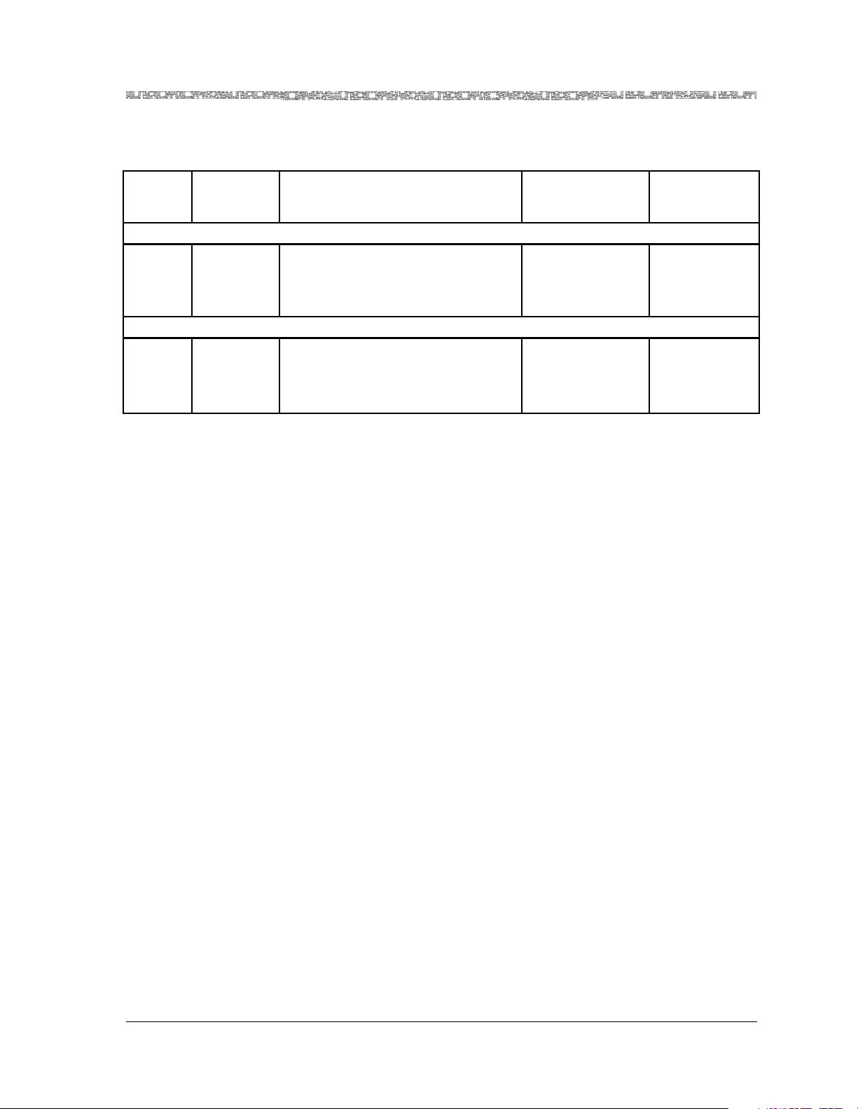
Table 2-5. System Software Release 6.2.0 DSP2x Voice Server Features
Chapter 2 Modules Description
Hardware Features
Release
7.0
Modes
Prior Release
7.0 Modes
Voice Processing Standards
Supported
DSP2A Features
AlgoSet2 DSP2A G726-voice-compression
G165-echo-cancellation
Generic-silence-suppression
Fax-modem-tone-detection
DSP2B Features
AlgoSet3 DSP2B G165-echo-cancellation
Fax-modem-tone-detection
G729a-voice-compression
G729b-silence-suppression
Hardware Features
• The DSP2A, DSP2B, and DSP2C Voice Server modules each have 32 DSP
chips supporting voice processing features.
• The DSP2D Voice Server module has 48 DSP chips supporting voice processing features.
• The DSP2E Voice Server module has eight DSP chips supporting voice and
Packet Pipe AAL5-to-AAL2 Wireless Trunking applications. The frame size
supported ranges from 15 to 256 bytes. Chips 1 through 6 exclusively process voice, providing 48 TDM voice channels (eight channels per chip).
Chips 7 and 8 exclusively process data for AAL5-to-AAL2, providing 168
Packet Pipe voice/data channels (84 channels per chip). The capacity of the
DSP2E makes it most appropriate for applications either at base stations or
in small hub sites between base stations and the CO.
• The DSP2F Voice Server module has eight DSP chips exclusively supporting
Packet Pipe voice/data channels for wireless applications. This hardware
configuration supports processing for 672 Packet Pipe voice/data channels,
providing 84 channels per chip.
AAL Mode
Non-multiplexed
AAL2
Non-multiplexed
AAL2
Number of
Channels
128
(4 channels per
chip)
128
(4 channels per
chip)
All modules connect the CPU and the other modules by a backplane connection.
Hardware Specifications
Table 2-6 shows the general physical and environmental hardware specifications for the I/O and server modules.
PacketStar® DSP2x Voice Server Modules User Guide, Issue 1 Release 8.0.0
255-700-251 2-21
Page 48

Chapter 2 Modules Description
Chassis Speed, Power Consumption, and Memory Allocation Specifications
Table 2-6. Physical Hardware Specifications for the I/O and the Server Modules
Specification Description
Dimensions 17.3 cm H x 2.41 cm W x 23.2 cm D
(6.8 in. H x 0.95 in. W x 9.13 in. D)
Weight 0.45 kg (1.0 lb.)
Operating temperature 0° to 50° C (32° to 122° F)
Operating humidity 5% to 85% relative humidity
Storage temperature -40° to 70° C (-40° to 158° F)
Chassis Speed, Power Consumption, and Memory Allocation
Specifications
Table 2-7 describes the chassis speed, power consumption, and memory allocation specifications for this module.
Table 2-7. Performance and Power Specifications for the DSP2x Voice Server Modules Module
To ta l
Module
DSP2B Voice Server
DSP II)
(
DSP2C Voice Server
(DSP2C)
DSP2D Voice Server
(DSP2D)
DSP2E Voice Server
(DSP2E)
DSP2F Voice Server
(DSP2F)
*
The I/O buffers carry 16,384 cells per megabyte for all PSAX modules except the 4-Port Voice 2-Wire
Office module, the 8-Port Voice 2-Wire Station module, and the DSP2
have no cells carried on the I/O buffers.
†
Indicates the size of the output buffer followed by the maximum number of 64-byte cells in the output
buffer.
‡
This column relates only to the speed at which the modules communicate within the chassis. A highspeed module will communicate at high speed (1.23 Gbps) in a chassis that has a high-speed bus
(PSAX 4500 chassis). High-speed modules will communicate at 650 Mbps in any other chassis. Lowspeed modules will always communicate at 650 Mbps in any chassis.
Amount of
SDRAM
512 KB
(SRAM)
1MB
(SRAM)
2MB
(SRAM)
2MB
(SRAM)
2MB
(SRAM)
Module
Program and
Data Space
384 KB
Maximum
Input
Buffer
*
Output
Buffer
†
N/A N/A Low
(SRAM)
512 KB
N/A N/A Low
(SRAM)
2MB N/A N/A High
2MB N/A N/A High
2MB N/A N/A High
x Voice Server modules, which
Chassis
Speed
Speed
Speed
Speed
Speed
Speed
‡
Consumption
Power
14 W
17 W
15 W
13 W
13 W
LED Indicators
PacketStar® DSP2x Voice Server Modules User Guide, Issue 1 Release 8.0.0
2-22 255-700-251
Page 49
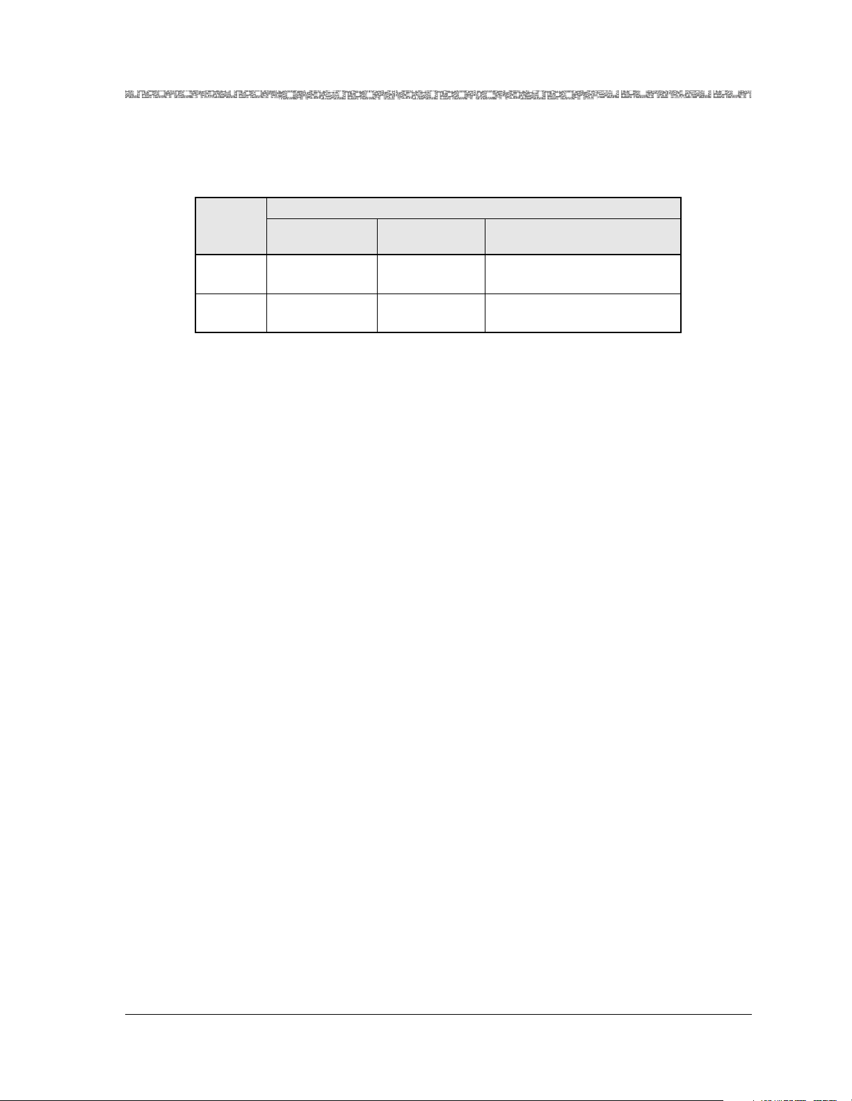
Chapter 2 Modules Description
Table 2-8 describes how the light-emitting diode (LED) indicators on the
DSP2x Voice Server modules faceplates respond to different module conditions. These LEDs indicate if the module has been installed properly.
Table 2-8. LED Indicators for the DSP2x Voice Server Modules
Module Status
LED
FAIL (red) Lights briefly
Initial Power-On
†
Not lit Lights only when the module
No
Configured Ports
One or More Configured Ports
is not functioning
ACTIVE
Lights briefly
(green)
*
The ports on this module are internal hardware. There are no external ports to
which to attach cabling on this module.
†
After power-on and the system boot is complete, the FAIL and ACTIVE LEDs
indicate whether the module has no configured ports (red), or one or more configured ports (green). The FAIL LED indicates a failed module.
†
Not lit Lights only when the module
is functioning properly
LED Indicators
*
PacketStar® DSP2x Voice Server Modules User Guide, Issue 1 Release 8.0.0
255-700-251 2-23
Page 50

Chapter 2 Modules Description
LED Indicators
PacketStar® DSP2x Voice Server Modules User Guide, Issue 1 Release 8.0.0
2-24 255-700-251
Page 51

3 Maximizing DSP Resource Use on the DSP2C
Through DSP2F Voice Server Modules
Overview of This Chapter
Configuring and utilizing the resources of the DSP2x modules are, in general,
relatively simple, but we recommend the procedural constraints described in
this chapter to maximize module performance. These procedural constraints
apply in complex networking environments in which there are multiple
DSP2x modules, multiple trunk groups for voice, fax, and modem traffic,
multiple packet sizes on varying interface protocols transmitting into and out
of a PSAX chassis.
Procedural and Configuration Constraints
The constraints outlined in this chapter apply only to the standard AAL2
multiplexing mode of the DSP2C voice server module, not necessarily to the
non-multiplexed AAL2 mode of the module.
Note: In this discussion, for the sake of clarity, the term “DSP” refers to
any of the 32 hardware chips on the DSP2C module. The number
of channels or connections that can be configured through a chip
depends on the algorithm set (AlgoSet) chosen. Table 3-1 below
describes the configuration modes available on the DSP2C Voice
Server Module with System Software Release 7.0. Chapter 4 of this
user guide contains specific instructions on configuring the channels on the DPS2C module.
.
Table 3-1. System Software Release 8.0 DSP2x* Voice Server Module Configuration Modes
Release 8.0
Modes
AlgoSet1 Echo
AlgoSet2 DSP2A G726-voice-compression
AlgoSet3 DSP2B G729a-voice-compression
PacketStar® DSP2x Voice Server Modules User Guide, Issue 1 Release 8.0.0
255-700-251 3-1
Prior to
Release 7.0
Modes
Cancellation
Voice Processing Standards
Supported
G168-echo-cancellation128ms
G165-echo-cancellation
Generic-silence-suppression
Fax-modem-tone-detection
G168-echo-cancellation64ms
G165-echo-cancellation
G729b-silence-suppression
Fax-modem-tone-detection
G168-echo-cancellation64ms
§
§
AAL Mode
†
Non-multiplexed
AAL2, or
Standard AAL2
Non-multiplexed
AAL2
(The DSP2C also
offers Std AAL2
with AlgoSet2)
Non-multiplexed
AAL2
Number of
Channels
336
(7 connections
per channel)
192
(4 connections
per channel)
192
(4 connections
per channel)
Page 52

Chapter 3 Maximizing DSP Resource Use on the DSP2C Through DSP2F Voice Server Modules
Procedural and Configuration Constraints
Table 3-1. System Software Release 8.0 DSP2x
Release 8.0
Modes
AlgoSet4‡Fax Relay
Prior to
Release 7.0
Modes
Mode
Voice Processing Standards
V17-fax-algorithm-upto-14400-bps
V29-fax-algorithm-upto-9600-bps
*
Voice Server Module Configuration Modes Continued
Supported
V27ter-fax-algorithm-upto-2400bps
V21-fax-algorithm-upto-300-bps
AlgoSet5 N/A G168-echo-cancellation64ms
AlgoSet6
(emulates
all fea-
tures of
the
DSP2C
Voice
Server
Module)
N/A G726-voice-compression
G729a-voice-compression
G729b-silence-suppression
G168-echo-cancellation64ms
Fax-modem-tone-detection
V17-fax-algorithm-upto-14400-bps
V29-fax-algorithm-upto-9600-bps
V27ter-fax-algorithm-upto-2400bps
V21-fax-algorithm-upto-300-bps
AlgoSet7
GR-303
**
N/A Hdlc-on-I366-1-AAL2-frame-mode Standard AAL2 672
N/A N/A Standard AAL2 1152
Connec-
tion Mon-
itoring
AAL Mode
Number of
Channels
Standard AAL2 128
(4 connections
per channel)
†
AAL1 1008
(21 connections
per channel)
Standard AAL2 384
¶
(21 connections per
channel)
§
(84 connections per channel)
(24 connections
per channel)
*
On the DSP2C Voice Server, the channels are configurable in any combination of voice processing
AlgoSets 1 through 4, but it is not recommended. Please read the cautions in Chapter 3 of the DSP2x Voice
Server Module User Guide when configuring large numbers of DSP connections in complex networking
environments with multiple trunk groups for voice, fax, and modem traffic in a PSAX chassis.
†
This feature comes with full-time fax tone detection/bypass, a feature that is always turned on regardless
of the AAL mode selected. The full-time fax tone detection/bypass is automatic and cannot be turned off
by the user when echo-cancellation only mode is selected for the DSP2C (AlgoSet1), and the DSP2D
(Algoset5).
‡
This option is not supported in System Software Release 7.1 and subsequent on the DSP2D module, but is
provided by Algoset6.
§
You can select the type of fax tone detection and subsequent firmware action you want on the CE-toATM DSP parameters connection windows. See the DSP Fax Tone Detection Modes Table in the Reference Information Appendix in this guide for the four modes available.
¶
See specific AAL2 configuration considerations in Chapter 7 and 8 of the appropriate Module User Guide.
**
AlgoSet7 is not available on the DSP2D Voice Server.
PacketStar® DSP2x Voice Server Modules User Guide, Issue 1 Release 8.0.0
3-2 255-700-251
Page 53

Chapter 3 Maximizing DSP Resource Use on the DSP2C Through DSP2F Voice Server Modules
Engineering Planning
Engineering Planning
We highly recommended that you develop an engineering plan before provisioning the connections on the DSPs of each module. The plan should
include these elements:
1. The number of DSP2C modules, which depends on the total number of
trunk groups required, and the number of connections within each
trunk group.
2. The addition of a few connections (or DSPs) to account for growth, even
if they are not immediately needed or provisioned.
3. The number of trunk groups. Plan to assign each trunk group to a single
DSP2C module. More than one trunk group can be assigned per module
if the total connections of all trunk groups stay within the maximum
capacity of 128 connections on the module. The type of information
needed per trunk group should include:
~ The size of the trunk group (number of DS0 connections)
~ The type of voice processing for entire trunk group. Choose Algorithm
Set 2 (AlgoSet2), or Algorithm Set 3 (AlgoSet3). (Athough mixing of
AlgoSet2 (DSP2A) and AlgoSet3 (DSP2B) voice processing modes on one
DSP2C module is allowed, it is not recommended).
~ The number of fax relay connections needed by the trunk group. At least
one chip per DSP2C module must be configured for AlgoSet4 (fax relay
mode) if the module is to process any incoming fax calls.
How the Module Firmware Handles Fax Calls
In the case of fax relay connections, when a fax call is detected and the call is
transferred to a chip configured for AlgoSet4 (fax relay mode), the original
voice processing chip is not free for use by any other call. The master CPU in
the PSAX is not aware that the transfer has taken place. In effect, the call is
using two DSP chip resources for one connection. The first is a permanent
voice AlgoSet2 or AlgoSet3 connection, and the second is a temporary fax
connection for the fax call. Once the number of fax relay mode (AlgoSet4)
connections are assigned, subtract this number from the available connections remaining (out of 128 total) on the given DSP2C module for assignment to pure voice processing connections. See “Channel Reduction Availability Caused by Fax Relay Connections vs. Voice Processing Connections on
a DSP2C Module” in the Reference Table appendix of the PacketStar
Voice Server Modules User Guide, and your chassis User Guide(s), for details on
the reduction of voice processing channel availability due to configuring DSP
resources for fax relay mode service (AlgoSet4). “ATM User-Network Interface Specification, Version 3.1, Cause Codes” in the Reference Table appendix shows the tone detection settings available on the CE-to-ATM VCC PVC
connection window.
®
DSP2x
PacketStar® DSP2x Voice Server Modules User Guide, Issue 1 Release 8.0.0
255-700-251 3-3
Page 54

Chapter 3 Maximizing DSP Resource Use on the DSP2C Through DSP2F Voice Server Modules
Provisioning Rules
Provisioning Rules
Follow the rules below to provision the functions and connections of each
DSP2C module.
Rule 1. Configure your largest AAL2 groups first.
Configure your largest AAL2 trunk groups first, and keep a record of each
connection in each group, as it is assigned. This rule serves a dual purpose
(see bullets below):
• Configuring and adding your largest groups first assures that the CPU will
process them in a locked cache (for example, one group of 224 channels in
Echo Cancel mode). A locked cache assures that the host processor will not
move data in and out of the cache. Data in a locked cache stays in the
locked cache until it is processed out and sent on its way. While we have
determined through testing that large AAL2 trunk groups (e.g., 224 connections) are processed with no problems, we nevertheless advise locked
cache processing of large AAL2 trunk groups (more than 128 trunk group
members).
Note: If you have large group(s) to configure, and the need for fax relay
on the same module, remember that at least one chip on the module must be configured for AlgoSet4 (fax relay mode). See “Rule
3. To process fax calls, at least one channel must be configured as
AlgoSet4 mode (fax relay).”).
• If a problem develops with a particular connection, knowing where the
connection originates and terminates should minimize the time spent on
the troubleshooting process.
Rule 2. Configure as many connections as possible on one DSP2C module before
configuring the next DSP2C module.
Configure one DSP2C module at a time, until either all its DSP resources and
connections to those resources are either assigned or are left unassigned.
(Although this is not an absolute imperative, it is recommended that at the
initial setup of the CPU database, only one DSP2C module be configured).
Assign or configure only those DSPs that will be needed according to your
engineering plan. When you assign trunk group members to DSPs, keep in
mind that all members of any one trunk group must fit on one module. You
may not split the membership of any trunk group between DSP2C modules;
that is, supposing you want to configure a trunk group of 224 echo cancel
connections. You may not assign some members of this trunk group to one
DSP2C module, and other members of the same trunk group to another
DSP2C module. If you do so, when you attempt to add a connection of the
CE-to-ATM VCC PVC Connection window, the CPU will return an error message “DSP resources unavailable”. See the “Example Configuration Scenario:
Connection Assignment Order Constraints” for a detailed explanation of why
the error message occurs.
PacketStar® DSP2x Voice Server Modules User Guide, Issue 1 Release 8.0.0
3-4 255-700-251
Page 55

Chapter 3 Maximizing DSP Resource Use on the DSP2C Through DSP2F Voice Server Modules
Provisioning Rules
Rule 3. To process fax calls, at least one channel must be configured as AlgoSet4 mode (fax relay).
If fax relay mode is desired on any DSP2C module, at least DSP must be configured as fax relay (AlgoSet4). The following analogy helps explain why.
Think of the DSP2C as a building, which has 32 rooms (or DSP chips). The
building has a capacity of at most 128 phone lines (four per DSP chip). Four
of these phone lines run to each room in the building. Depending on the
anticipated mix of fax users vs. voice users (which likely to be much less than
half of all users), it is not prudent to assign a fax machine (i.e., a DSP chip
with AlgoSet4) for each line in the building. Instead, it is best to assign a
small number of the rooms for fax machines only (fax relay mode chipsets)
and the remaining just for voice users. If five rooms (or chipsets) are assigned
for fax on a given DSP2C server module, then:
5 chips X 4 channels per chip = 20 of the available phone line connections
have been reserved for fax only.
In the other 27 rooms, the phone lines can be assigned for voice (either
G.726-DSP2A mode or G.729-DSP2B mode). This means there are:
27 chips left X 4 channels per chip = 108 phone lines available for voice connections.
If a given DSP chip (for a given room) is set in either a AlgoSet2 or AlgoSet3
mode, and the voice user needs to make a fax call, the user connection must
be transferred to one of the fax rooms (i.e., DSPs in AlgoSet4 [fax relay]
mode). If there is an available fax machine (DSP chip set for fax mode), a fax
call can be sent. If there is no available DSP in fax mode, then a fax call cannot be sent. After a user completes a fax call, the machine (i.e., a DSP chip in
fax relay mode) is made available for another connection by another user
who wishes to use it.
If fax relay mode service is to be supported for a portion of all user connections, this design approach requires that a certain number of DSP chipsets on
the DSP2C must be configured as fax relay mode. The number of chipsets
depends on the expected fax traffic, as determined by the up front engineering plan of expected user service demand for fax connections. The assignments of additional fax-configured chipsets on a DSP2C module will allow
more fax calls but at the cost of reducing the number of DSPs that are available for voice calls. These fax-configured chipsets are resources that are
shared by all the remaining chipsets on a given DSP2C module. Recall from
“How the Module Firmware Handles Fax Calls” that even when the call
transfers to the fax-configured chip, the primary AlgoSet2/AlgoSet3 voice
processing chips are still associated with the connection and cannot be used
for new connections.
Rule 4. To maximize DSP2C resource performance, avoid mixing the DSP
configuration modes on the same module.
You must understand that once two or more DSP2C modules are configured
in a PSAX chassis, you have no direct control of how these resources are utilized by the master CPU in the PSAX as connections are added or deleted.
Therefore, it is recommended that when using more than one DSP2C module
PacketStar® DSP2x Voice Server Modules User Guide, Issue 1 Release 8.0.0
255-700-251 3-5
Page 56

Chapter 3 Maximizing DSP Resource Use on the DSP2C Through DSP2F Voice Server Modules
Example Configuration Scenario: Connection Assignment Order Constraints
in a PSAX chassis, that a mix of AlgoSet2 (G.726 compression), AlgoSet3
(G.729a compression and G.729b silence suppression) and AlgoSet1 (Echo
Cancel modes, G.165, G.168) not be used on the same module. Although it is
possible to mix these compression and echo cancellation modes among separate DSP chips, due to the design of the CPU database in the PSAX, it is more
straightforward procedurally to assign only one type of DSP compression
mode for the entire module. This is due to how that the CPU database allows
assignment of DSP resources and interface module connections. This assignment process involves knowledge of the order of configuration of these
resources and knowledge of usage priorities for the DSP resources, which
makes managing the CPU database complex. This rule applies to those
remaining DSPs on a module that have not been configured for fax relay
mode.
Rule 5. Understand and use the "modularity principle" for each DSP2C Algorithm Set.
If all connection resources on a given DSP2C chipset module are not fully
assigned, there may be a need to establish dummy connections on any
remaining available connection resources. This is due to the modularity of
each DSP chip, which supports up to 4 connections each. Thus, if only 2 of
the 4 connections on a DSP chip are unassigned, the unused 2 connections
must be "dummied", that is, assigned to another E1/DS1 port before further
provisioning can be done on another DSP2C module (see “Example Configuration Scenario: Connection Assignment Order Constraints”). Remember
that not all DSP channels need to be assigned. If left unassigned, the CPU
logic will allow provisioning of other DSP2C modules in the chassis.
Example Configuration Scenario: Connection Assignment
Order Constraints
The following scenario illustrates Provisioning Rule 2, which prohibits splitting a trunk group between two DSP2C modules. For simplicity, assume that
fax relay mode is not used. Assume there are two DSP2C modules, both configured as AlgoSet3 (G.729a) mode, and standard AAL-2, for all DSP chipsets.
Assume that two trunk groups of AAL-2 connections are to be set up using
these DSP2C modules, Trunk Group A and Trunk Group B. Trunk Group A
will have 100 connections, and Trunk Group B will have 40 connections.
Since there are two DSP2C modules, there is a total resource of:
1 module X 4 connections per chipset X 32 chipsets = 128 connections per
module
2 modules X 128 connections per module = 256 connections
As Trunk Group A is set up with the 100 connections, all the connections will
be assigned to whichever DSP2C module was configured first (per Provisioning Rule 2 above). One hundred connections use 25 chipsets on the module:
25 chipsets X 4 connections per chipset = 100 connections
Now there are 7 chipsets left on the module: 32 - 25 = 7
PacketStar® DSP2x Voice Server Modules User Guide, Issue 1 Release 8.0.0
3-6 255-700-251
Page 57

Chapter 3 Maximizing DSP Resource Use on the DSP2C Through DSP2F Voice Server Modules
Example Configuration Scenario: Connection Assignment Order Constraints
Then Trunk Group B is set up with 40 connections. This will require 10
chipsets:
40 connections / 4 connections per chipset = 10 chipsets. You can see that
this will involve splitting the second group of 40 connections between 2
modules.
On the CE-to-ATM VCC PVC connection window, when adding the first 28
Trunk Group B connections, (28/4 = 7, which will use the remaining 7
chipsets), each connection will be acknowledged as being added by the master CPU. They are assigned to remaining connection resources of the first
DSP2C module.
When trying to add the 29th connection of Trunk Group B, however, it will
be rejected and the system will say "DSP resources unavailable". The reason
for this is that the CPU will attempt to put the 29th connection on the same
module as the other connections having the the same virtual path indicator
(VPI) and the same virtual channel indicator (VCI). (Remember that all trunk
group members in the same group have the same VCI and VPI, see
Figure 3-1). The CPU cannot do so, however, because the all DSP resources
on that module are taken by all of Trunk Group A (100 connections), and the
first 28 connections of Trunk Group B. The CPU, therefore, returns the error
message.
Figure 3-1. AAL2 Trunking Architecture
If you desire to establish Trunk Group B (40 connections), the recommended
procedure is to not assign any resources to the 7 unused DSP chipsets on the
first module, that is, leave them unconfigured. This forces the CPU logic to
move to additional DSP resource assignments to the next (second) DSP2C
module, on which Trunk Group B can be assigned.
PacketStar® DSP2x Voice Server Modules User Guide, Issue 1 Release 8.0.0
255-700-251 3-7
Page 58

Chapter 3 Maximizing DSP Resource Use on the DSP2C Through DSP2F Voice Server Modules
Suggestion for Quicker Provisioning
Alternatively, one could temporarily assign 28 dummy connections on these
remaining 7 DSP chipsets of the first DSP2C module using 8k compression to
force the master CPU to start using the second DSP module. This is mentioned in Rule 5 above. Then the additional 40 connections of Trunk Group B
would be assigned to the second DSP2C module.
Only after making the Trunk Group B connections to the second DSP2C
module resources, can you delete the 28 dummy connections on the first
DSP2C module so as to free the ingress circuit emulation, egress ATM and
DSP resources for use by other connections. Only when the remaining connections on the second DSP2C module are used, or left unassigned, will the
CPU database allow further connection assignments on the first DSP2C module, or additional modules in the chassis.
Suggestion for Quicker Provisioning
An alternate suggestion to simplify provisioning on a given module is to configure the first DSP chipsets on the module (it must be chipset 1) in the
mode desired for voice processing (either AlgoSet2 or AlgoSet3 mode). Then
configure all remaining DSPs and they will take the properties of the first
DSP. Then unassign a few DSPs at the end of the list and reconfigure them as
fax relay, as needed. This process can save a lot of time.
Wireless Transport Configuration Considerations on the DSP2D Through DSP2F Voice Server Modules
Using AAL2 on the DSP2D Voice Server Module
On the DSP2D Voice Server module, the PSAX CPU will allow you to make
up to 384 connections (8 per chip configured as AlgoSet6) on a VBR-toATM connection type. However, if you configure that number, the DSP2D
will fail, as the module cannot handle 64 Kbps traffic per DS0 with a mixture
of small and large packet sizes. Configure your packet sizes based on these
known outcomes:
• The module can process 96 DS0s sending 16 byte packets at 64 Kbps.
• A small percentage of frames will be lost on 96 DS0s sending 256 byte
packets at 64 Kbps.
When configuring the AAL2 trunk, the IWF Type field on the AAL2 Trunk
Connection Configuration window, should be set to None (the default)
when you set up the AAL2 trunk group. Within this trunk you can mix voice
(CE-to-ATM) and data (VBR-to-ATM).
Using AAL2 on the DSP2F Voice Server Module
On the DSP2F Voice Server module, the PSAX CPU will allow you to configure up to 672 connections (84 per chip configured as AlgoSet7) on
VBR-to-ATM connections. However, if you configure that number, the
DSP2F will fail, as the module cannot handle 64 Kbps traffic per DS0 with a
mixture of small and large packet sizes.Configure your packet sizes based on
these known outcomes:
PacketStar® DSP2x Voice Server Modules User Guide, Issue 1 Release 8.0.0
3-8 255-700-251
Page 59

Chapter 3 Maximizing DSP Resource Use on the DSP2C Through DSP2F Voice Server Modules
Wireless Transport Configuration Considerations on the DSP2D Through DSP2F Voice Server Modules
• The module can process 672 DS0s sending 16 byte packets at 64 Kbps.
• A small percentage of frames will be lost on 256 byte packets transmitted at
64 Kbps.
When configuring the AAL2 trunk, set the IWF Type field on the AAL2
Trunk Connection Configuration window to Packet-pipe. Within this trunk
you cannot mix voice (CE-to-ATM) and data (VBR-to-ATM). For this type of
connection, the DS0s can be strapped. Currently, the CAC is unaware of the
strapping and uses the PCR of the VBR-to-ATM connection to determine the
DSP load when less than 84 connections per chip are used. Using the configured PCR rate can cause the CPU to overload the DSP2F if the user does not
configure the connection setups correctly.
DSP Chip Architecture and Connection Loads
Each chip configured as AlgoSet7 can support a maximum of 84 DS0s each
at 64 Kbps with 16 byte packets. The data flow sequence is:
Data in to DSP module from backplane –> DSP host processor –> DSP chip –>
Back out through DSP host processor –> Out through Backplane to ATM
module. (See Figure )The data passes through buffers before processing, in
the host (pure voice) and also through the DSP chip buffer on its way in and
out. The number of cells per second transmitting from the backplane to the
DSP host processor will not match the cellsp per second exiting from the DSP
chip back to the host. The cps exiting from the DSP chip varies greatly
depending on a number of factors but primarily on the byte size of the
packet.
Using AAL2 on the DSP2F Voice Server Module
On the DSP2E, configure the first six chips exactly like the DSP2D, and the
last 2 chips exactly like the DSP2F.
PacketStar® DSP2x Voice Server Modules User Guide, Issue 1 Release 8.0.0
255-700-251 3-9
Page 60

Chapter 3 Maximizing DSP Resource Use on the DSP2C Through DSP2F Voice Server Modules
Wireless Transport Configuration Considerations on the DSP2D Through DSP2F Voice Server Modules
PacketStar® DSP2x Voice Server Modules User Guide, Issue 1 Release 8.0.0
3-10 255-700-251
Page 61

4 Configuring DSP Resources Using
the Console Interface System
DSP Resource Configuration
The DSP Resource feature is available in PSAX system software beginning
with PacketStar PSAX Release 7.1.0. The DSP Resource Configuration Menu
Option was added to the Site-Specific Menu with PacketStar PSAX
Release 8.0.0.
DSP Resource Assignment With ATM Trunking Bearer VCCs Coordination
If you want to assign DSP resource management as Manual or Automatic,
you must do so by using the DSP Resource Configuration option on the Site
Specific Menu
After channel configuration, if you want to change the DSP resource
management from Manual to Automatic, or vice versa, the PVCs will be
lost and the SPVCs remain intact. It is critical that the Dsp Select Type field on
the ATM Trunking Bearer VCC Configuration window be set to the
value, either Manual or Automatic, as the Selection Type field on the Dsp
Resource Managment table off the site specific menu, or the connections you
configure with DSP parameters will never be assigned and activate.
before proceeding to DSP2x module channel configuration.
same
Note: The DSP Resource Configuration Option does not support the V5.2
ELCP protocol or GR-303 LES protocol. The system-wide DSP
Rerouting option is disabled by default on the DSP Resource Table
window. The DspReroutingFeature field enables or disables the
feature. If you are configuring DSP resources for V5.2 or GR-303,
leave the feature at its default (disabled).
The following procedure, Viewing the DSP Resource Table, sets the use of
DSP resources at the PSAX system level for Manual or Automatic assignment. More specific parameters are configured on the AAL2 Trunking Connection Configuration window (see the PacketStar
Provisioning Guide for details).
Perform the steps in the following procedure to view DSP resources status
and to set or disable automatic rerouting of DSP resources in case of failure of
individual DSPs.
®
PSAX System Connections
PacketStar® DSP2x Voice Server Modules User Guide, Issue 1 Release 8.0.0
255-700-251 4-1
Page 62

Chapter 4 Configuring DSP Resources Using the Console Interface System
DSP Resource Configuration
Viewing the DSP Resource Table
Begin
Note: (See your PSAX System User Guide, Chapter 4, for instructions on
accessing the window in Figure 4-1). From the Console Interface
Main Menu (not shown), select the Site Specific Configuration
option). A table describing the options on the window in
Figure 4-1 is in Chapter 4 of your PSAX System User Guide.
1 Select the DSP Resource Configuration option shown in Figure 4-1. The
DSP Resource Feature Menu is displayed (see Figure 4-3). The command table immediately follows Figure 4-3.
2 Remain on this window and continue to the next procedure, Accessing
the DSP Resource Table.
End
Figure 4-1. Site-Specific Menu, DSP Resource configuration Selected
PacketStar® DSP2x Voice Server Modules User Guide, Issue 1 Release 8.0.0
4-2 255-700-251
Page 63

Chapter 4 Configuring DSP Resources Using the Console Interface System
DSP Resource Configuration
Figure 4-2. DSP Resource Feature Menu
Command Function
DSP Resource Table Displays the DSP Resource Table window.
DSP Resource Management
Tabl e
Go Back to Site Specific
Menu
Displays the Dsp Resource Management
Table wind ow.
Returns to the Site-Specific Menu
window.
Accessing the DSP Resource Table
Begin
1 From the DSP Resource Feature Menu, select the DSP Resource Table
option. The DSP Resource Table is displayed (see Figure 4-3). The command table and display-only table immediately follow Figure 4-3.
2 Select the option you want for DSPReroutingFeature field.
3 Select the Apply Rerouting Configuration command.
4 Select the Go Back to DSP Resource Menu command and continue
with the next procedure.
End
PacketStar® DSP2x Voice Server Modules User Guide, Issue 1 Release 8.0.0
255-700-251 4-3
Page 64

Chapter 4 Configuring DSP Resources Using the Console Interface System
DSP Resource Configuration
Figure 4-3. DSP Resource Table
Display Field Function
Tota l:
1/10
The first number in this field indicates the number of
the DSP resource table entry on the first line of the
currently displayed window. The second number indicates the total number of DSP resource table entries for
this AlgoSet type.
Resource ID Identifies the type of AlgoSet displayed on the table.
Avai l The total number of DSP resources available in the
selected AlgoSet type.
Used The total number of DSP resources currently used for
the selected AlgoSet type.
Avail Failed The total number of DSP resources available in the
selected AlgoSet type that are currently failed.
Used Failed The total number of DSP resources for the selected
AlgoSet type currently in use that are failed.
Command Function
Page Up Scrolls up one page.
Page Down Scrolls down one page.
Top Displays entries at the top of the table.
PacketStar® DSP2x Voice Server Modules User Guide, Issue 1 Release 8.0.0
4-4 255-700-251
Page 65

Chapter 4 Configuring DSP Resources Using the Console Interface System
d
DSP Resource Configuration
Command Function
Bottom Displays entries at the bottom of the table.
Apply Rerouting
Configuration
Go Back to DSP Resource
Menu
:
Table 4-1. Field Descriptions for the DSP Resource Table Window
Field Name Field Values Description
DspRerouting
Feature
Default: Auto-
rerouting-enabled
Range: N/A
Format: Predefined
Auto-rerouting-
Displays failed DSP connections to be transferred
to other DSP resources if the originally configured DSP resources fail. Failed connections will
reroute only if DSP resources are available.
Enables auto rerouting.
Applies the selected value in the DspReroutingFeature field.
Redisplays the DSP Resource Feature
Menu window.
enabled
Disabled Disables auto rerouting.
V5.2 and GR-303 Applications: Do not change
this value. DSP Rerouting is not supported for
these protocols.
Accessing and Viewing the Dsp Resource Management Table
Begin
1 From the DSP Resource Feature Menu (see Figure 4-2), select the DSP
Resource Management Table command. The Dsp Resource Management
Table is displayed (see Figure 4-4). Table 1-2 describes the display only
fields on the window.
En
PacketStar® DSP2x Voice Server Modules User Guide, Issue 1 Release 8.0.0
255-700-251 4-5
Page 66

Chapter 4 Configuring DSP Resources Using the Console Interface System
DSP Resource Configuration
Figure 4-4. DSP Resource Management Table
PacketStar® DSP2x Voice Server Modules User Guide, Issue 1 Release 8.0.0
4-6 255-700-251
Page 67

Chapter 4 Configuring DSP Resources Using the Console Interface System
Table 4-2. Field Descriptions for the DSP Resource Management Table
Field Name Field Values Description
Card Slot Default: N/A
Range: Chassis
dependent
Format: Numeric
Identifies the slot available by number on the
PSAX System chassis used. If you have DSP modules in your chassis and you select the DSP
Resource Managment Table option on the DSP
Resource Feature Menu window, the chassis software automatically selects the first DSP module
in the chassis upon first display of the DSP
Resource Management Table window.
Selection Type Default: Automatic
Range: N/A
Format: Predefined
Specifies whether the slot is occupied by a DSP2x
module or not.
• The default Automatic displays for slots occu-
pied by a DSP2x module.
• The default Unsupp displays for a slot occu-
pied by a module that is not a DSP module.
PVC Configuration: The setting you select in this
must match the setting in the DSP Resource
field
Selection field on the AAL2 Trunk Connection
Configuration window, or your connections will
not be made.
DSP Resource Configuration
SPVC Configuration: The setting you select in this
must match the setting in the Dsp Select
field
Type field on the ATM Trunking Bearer VCC Configuration window, or your connections will not
be made.
Automatic The DSP resource manager selects primary and
backup DSPs from a chassis-wide pool in case of
DSP failure. The switch to backup DSPs, when
made, is nonrevertive.
Unsupp The module in this slot is not a DSP module.
Manual In case of DSP failure, the DSP resource manager
selects primary and backup DSPs from a particular module designated in Dsp Slot Id field on the
AAL2 Trunk Connection window, right panel.
The switch to backup DSPs, when made, is nonrevertive.
PacketStar® DSP2x Voice Server Modules User Guide, Issue 1 Release 8.0.0
255-700-251 4-7
Page 68
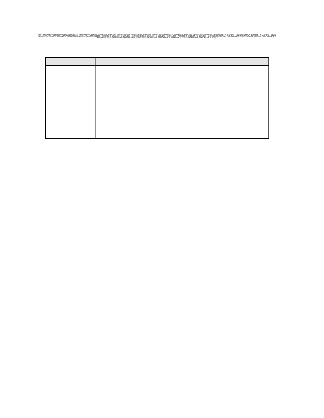
Chapter 4 Configuring DSP Resources Using the Console Interface System
DSP Resource Configuration
Table 4-3. Field Descriptions for the DSP Resource Table Window
Field Name Field Values Description
DspRerouting
Feature
Default: Auto-
rerouting-enabled
Range: N/A
Format: Predefined
Auto-rerouting-
Displays failed DSP connections to be transferred
to other DSP resources if the originally configured DSP resources fail. Failed connections will
reroute only if DSP resources are available.
Enables auto rerouting.
enabled
Disabled Disables auto rerouting.
V5.2 and GR-303 Applications: Do not change
this value. DSP Rerouting is not supported for
these protocols.
PacketStar® DSP2x Voice Server Modules User Guide, Issue 1 Release 8.0.0
4-8 255-700-251
Page 69

5 Configuring DSP Resources Using
the AQueView® System
DSP Resource Configuration
The DSP Resource feature is available in PSAX system software beginning
with PacketStar PSAX Release 7.1.0, and with the Multiservice Media Gateway EMS beginning with Release 5.1. The DSP Resource Mgmt Table tab was
added in with PacketStar PSAX Release 8.0.0, and with the Multiservice
Media Gateway EMS beginning with Release 6.0.
DSP Resource Assignment With ATM Trunking Bearer VCCs Coordination
If you want to assign DSP resource management as Manual or Automatic,
you must do so by using the DSP Resource Configuration option on the Site
Specific Menu
After channel configuration, if you want to change the DSP resource management from Manual to Automatic, or vice versa, the PVCs will be lost
and the SPVCs remain intact. It is critical that the Dsp Select Type field on the
ATM Trunking Bearer VCC Configuration window be set to the
either Manual or Automatic, as the Selection Type field on the Dsp
Resource Managment table off the site specific menu, or the connections you
configure with DSP parameters will never be assigned and activate.
before proceeding to DSP2x module channel configuration.
same value,
Note: The DSP Resource Configuration Option does not support the V5.2
ELCP protocol or GR-303 LES protocol. The system-wide DSP
Rerouting option is disabled by default on the DSP Resource Table
window. The DspReroutingFeature field enables or disables the
feature. If you are configuring DSP resources for V5.2 or GR-303,
leave the feature at its default (disabled).
Overview of DSP Resource Configuration Tasks
The following procedure, Viewing the DSP Resource Table, sets the use of
DSP resources at the PSAX system level for Manual or Automatic assignment. More specific parameters are configured on the AAL2 Trunking Connection Configuration window (see the PacketStar
Provisioning Guide for details).
Procedure 1
Begin
1 In the Device window, click the Site-Specific tab.
The Site-Specific page appears.
®
PSAX System Connections
PacketStar® DSP2x Voice Server Modules User Guide, Issue 1 Release 8.0.0
255-700-251 5-1
Page 70

Chapter 5 Configuring DSP Resources Using the AQueView® System
d
Overview of DSP Resource Configuration Tasks
2 Click the DSP Resource tab.
The DSP Resource Table page appears (see Figure 5-2).
3 Click the DSP Resource Mgmt Table tab.
The DSP Resource Mgmt Table page appears (see Figure 5-1).
Figure 5-1. DSP Resource Mgmt Table Page (Displaying Menu)
Slots where a DSP2x Voice Server module are present show the value
Automatic or Manual. All other slots show Unsupp.
4 Right-click the mouse and a menu appears. Select the appropriate value
for the slot as described in Table 0-2.
5 DSP Resource Table page, click Apply.
6 The Reset button restores the DSP Rerouting Feature field to the last
applied value.
En
PacketStar® DSP2x Voice Server Modules User Guide, Issue 1 Release 8.0.0
5-2 255-700-251
Page 71

Chapter 5 Configuring DSP Resources Using the AQueView® System
Overview of DSP Resource Configuration Tasks
Table 5-1. Field Descriptions for the DSP Resource Management Table
Field Name Field Values Description
Slot Id Default: N/A
Range: Chassis
dependent
Format: Numeric
Identifies the slot available by number on the
PSAX System chassis used. If you have DSP modules in your chassis and you select the DSP
Resource Managment Table option on the DSP
Resource Feature Menu window, the chassis software automatically selects the first DSP module
in the chassis upon first display of the DSP
Resource Management Table window.
Selection Type Default: Automatic
Range: N/A
Format: Predefined
Specifies whether the slot is occupied by a DSP2x
module or not.
• The default Automatic displays for slots occu-
pied by a DSP2x module.
• The default Unsupp displays for a slot occu-
pied by a module that is not a DSP module.
Automatic The DSP resource manager selects primary and
backup DSPs from a chassis-wide pool in case of
DSP failure. The switch to backup DSPs, when
made, is nonrevertive.
Unsupp The module in this slot is not a DSP module.
Manual In case of DSP failure, the DSP resource manager
selects primary and backup DSPs from a particular module designated in Dsp Slot Id field on the
AAL2 Trunk Connection window, right panel.
The switch to backup DSPs, when made, is nonrevertive.
Procedure 2
Perform the steps in the following procedures to configure digital signal processor resources.
Begin
1 In the Device window, click the Site-Specific tab.
The Site-Specific page appears.
2 Click the DSP Resource tab.
PacketStar® DSP2x Voice Server Modules User Guide, Issue 1 Release 8.0.0
255-700-251 5-3
Page 72

Chapter 5 Configuring DSP Resources Using the AQueView® System
d
Overview of DSP Resource Configuration Tasks
The DSP Resource Table page appears (see Figure 5-2).
Figure 5-2. DSP Resource Table Page
3 Select the appropriate value for the field described in Table 5-2.
4 Click Apply.
5 The Reset button restores the DSP Rerouting Feature field to the last
applied value.
En
PacketStar® DSP2x Voice Server Modules User Guide, Issue 1 Release 8.0.0
5-4 255-700-251
Page 73

Chapter 5 Configuring DSP Resources Using the AQueView® System
Overview of DSP Resource Configuration Tasks
Table 5-2. Field Descriptions for the DSP Resource Table Window
Field Name Field Values Description
DSP Rerouting
Feature
Default: Auto-
rerouting-enabled
Range: N/A
Format: Predefined
Auto-rerouting-
Displays failed DSP connections to be transferred
to other DSP resources if the originally configured DSP resources fail. Failed connections will
reroute only if DSP resources are available.
Enables auto rerouting.
enabled
Disabled Disables auto rerouting.
V5.2 and GR-303 Applications: Do not change
this value. DSP Rerouting is not supported for
these protocols.
PacketStar® DSP2x Voice Server Modules User Guide, Issue 1 Release 8.0.0
255-700-251 5-5
Page 74

Chapter 5 Configuring DSP Resources Using the AQueView® System
Overview of DSP Resource Configuration Tasks
PacketStar® DSP2x Voice Server Modules User Guide, Issue 1 Release 8.0.0
5-6 255-700-251
Page 75

6 Configuring Ports and Channels
Using the Console Interface
Overview of This Chapter
This chapter describes how to configure ports and channels for the DSP2x
Voice Server modules, which is upgradable to PSAX system Release 8.0.0,
and subsequent, on the PSAX system console interface. The configuration of
the standalone single-algoset DSP2A and DSP2B modules follow this section
(these modules are not upgradable beyond System Software Release 6.3.0).
To configure the DSP2x Voice Server modules, you must configure the DSP2
channels.
Configuring the Channels of the DSP2C, DSP2D, DSP2E, and DSP2F Voice Server Modules
The procedures and cautions for configuring the channels of the DSP2C
through the DSP2F modules are the same, with these differences:
• The DSP2C module has 32 channels (hardware chips); the DSP2D has 48
channels (chips)
• The DSP2C provides AlgoSet1 through AlgoSet4 (algorithm sets).
• The DSP2D provides AlgoSet1, 2, 3, 5, and 6.
• The DSP2E provides AlgoSet6 and 7.
• The DSP2F provides AlgoSet7.
You must configure the module before you can set up connections that use
its features. To configure channels for the module, and to bring the channels
into service, perform the steps in the following procedure.
Note: The channels and connections of the DSP2C Voice Server module
are configurable in any combination of the four AlgoSet voice processing modes; however, you are advised to read Chapter 3 of the
DSP2x Voice Server Modules User Guide for configuration cautions
when using large numbers of DSP connections in complex networking environments with multiple trunk groups for voice, fax,
and modem traffic in a PSAX chassis.
!
CAUTION:
Due to the copper wire interface between an Enhanced DS1 or E1 module with a PBX and/or key telephone system, the PSAX system and the
other equipment should use a common chassis ground connection to
avoid ground current loops, which could affect voice quality.
PacketStar® DSP2x Voice Server Modules User Guide, Issue 1 Release 8.0.0
255-700-251 6-1
Page 76

Chapter 6 Configuring Ports and Channels Using the Console Interface
DSP2C Through DSP2F Channel Configuration
DSP2C Through DSP2F Channel Configuration
Configuring the DSP2C or DSP2D Channels
Begin
1 On the Console Interface Main Menu window (see Figure 6-1), select
the Equipment Configuration option and press Enter (or press Ctrl+E).
Figure 6-1. Console Interface Main Menu
The Equipment Configuration windows (see Table 6-2) is displayed.
PacketStar® DSP2x Voice Server Modules User Guide, Issue 1 Release 8.0.0
6-2 255-700-251
Page 77
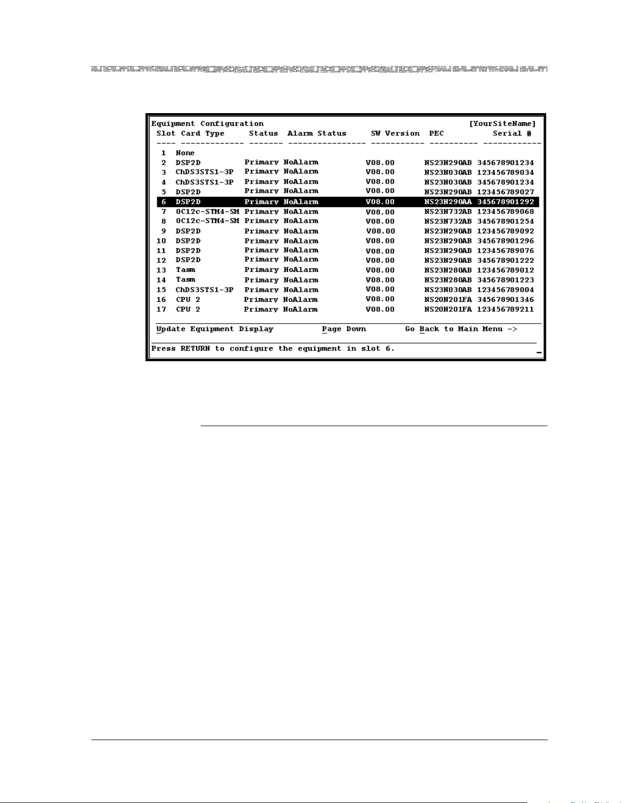
Chapter 6 Configuring Ports and Channels Using the Console Interface
DSP2C Through DSP2F Channel Configuration
DSP2C Through DSP2F Configuration Options
Figure 6-2. Equipment Configuration Window (As Displayed on the PSAX 4500
Console)
Configuring the DSP2C Through DSP2F Voice Server Modules for
AlgoSets1 through 7
Begin
Note: The port configuration fields and commands are the same for each
module type DSP2C through DSP2F, but different number of channels show on the window, depending on which module type you
are configuring.
1 On the Equipment Configuration window, select the DSP2x module you
want to configure and press Enter.
The DSP2C Port Configuration window is displayed in Figure 6-3.
The DSP2D Port Configuration window is displayed in Figure 6-4.
The DSP2E Port Configuration window is displayed in Figure 6-5.
The DSP2F Port Configuration window is displayed in Figure 6-6.
The values for the configuration screens in this chapter from Table 6-2.
The algorithm sets are detailed in Table 6-3.
2 On the DSP2x Port Configuration Window (Figure 6-4), select the DSP
channel number you wish to configure and press Enter.
The status line at the bottom of the window will prompt:
Unconfigured. Configure interface now (y/n) ?
3 Select y for yes and press Enter.
The Channel and Interface Configuration window is displayed.
PacketStar® DSP2x Voice Server Modules User Guide, Issue 1 Release 8.0.0
255-700-251 6-3
Page 78

Chapter 6 Configuring Ports and Channels Using the Console Interface
DSP2C Through DSP2F Channel Configuration
The DSP2C through the DSP2F Channel and Interface Configuration
windows are displayed in Figure 6-7 through Figure 6-10.
4 Proceed with the Configuring the Channel and Interface Configuration Win-
dow procedure below.
Figure 6-3. DSP2C Port Configuration Window (Before Configuration)
PacketStar® DSP2x Voice Server Modules User Guide, Issue 1 Release 8.0.0
6-4 255-700-251
Page 79

Chapter 6 Configuring Ports and Channels Using the Console Interface
DSP2C Through DSP2F Channel Configuration
Figure 6-4. DSP2D Port Configuration Window (Before Configuration)
Figure 6-5. DSP2E Port Configuration Window (Before Configuration)
PacketStar® DSP2x Voice Server Modules User Guide, Issue 1 Release 8.0.0
255-700-251 6-5
Page 80

Chapter 6 Configuring Ports and Channels Using the Console Interface
DSP2C Through DSP2F Channel Configuration
Commands
Figure 6-6. DSP2F Port Configuration Window (Before Configuration)
The commands on these windows have the following functions:
Table 6-1.
Command Function
Configure All Interfaces On
This Port
Configures all DSP interfaces for this port.
If the first DSP interface is configured, this
command will configure the remaining
interfaces the same way.
Delete All Interfaces On
This Port
Deletes all out-of-service configured interfaces.
You must first take all interfaces out of
service (using the Take All Interfaces
Out Of Service command) before you
can use this command.
Bring All Interfaces Into
Service
Brings the out-of-service configured interfaces to in-service status.
Note:
Take All Interfaces Out of
Service
Go Back to Equipment Configuration
Takes the in-service configured interfaces
to out-of-service status.
Redisplays the Equipment Configuration
window.
PacketStar® DSP2x Voice Server Modules User Guide, Issue 1 Release 8.0.0
6-6 255-700-251
Page 81

Chapter 6 Configuring Ports and Channels Using the Console Interface
DSP2C Through DSP2F Channel Configuration
Table 6-2. Field Descriptions for the DSP2C Through DSP2F Port Configuration Window
Field Name Field Values Description
Slot: Default: Varia ble
Range: Var iable
Displays the slot number containing the DSP2x Voice
Server module.
Format: Numeric
[Port:]
(display only)
Default: 01
Range: 1
Displays the internal port of the DSP2x Voice Server module.
Format: Numeric
DSP2C Admin
Status
DSP2D,
DSP2E,DSP2F
Opera
Status
Default:
Var iable by m odule
Range: (channels)
DSP2C: 1–32
DSP2D: 1–48
Displays the DSP chip administrative or operating status.
See the DSP Feature Matrix in chapter 4 of the DSP2x
Voice Server Module User Guide for chip capacities within
selected algoset. The algosets available for selection
depend on the module model and application used (see
field value at left).
DSP2E,DSP2F:1–8
Format: Predefined
Unconfigured Displays the interface available for configuration
InService Displays the interface configured. The right panel of win-
dow will show configuration type.
OutOfService Displays the interface not available; user selected.
[Algorithm
Type]
(display only)
Default:
Information
Unavailable
Range: N/A
Format: Predefined
Displays the default value indicating that the interface is
unconfigured.
Note: On the DSP2C module, after a DSP mode is applied
on the Port Configuration window, the algorithm parameters display in the right panel of the window.
Note: On the DSP2D, DSP2E, and DSP2F module, after a
DSP mode is applied on the Port Configuration window,
the algorithm parameters display in the lower left panel of
this window.
On the Port Configuration windows (Figure 6-3 through Figure 6-6), the
module DSP processor chips (channels) are displayed. Table 6-3 shows the
Algorithm Sets (AlgoSets) and channel capacities available for configuration
on any of the channels. The channel defaults for a new or unconfigured
module is Unconfigured.
PacketStar® DSP2x Voice Server Modules User Guide, Issue 1 Release 8.0.0
255-700-251 6-7
Page 82

Chapter 6 Configuring Ports and Channels Using the Console Interface
DSP2C Through DSP2F Channel Configuration
*
Table 6-3. System Software Release 8.0 DSP2x
Voice Server Module Configuration Modes
Release 8.0
Modes
Release 7.0
AlgoSet1 Echo
Prior to
Modes
Voice Processing Standards
Supported
G168-echo-cancellation128ms
Cancellation
AlgoSet2 DSP2A G726-voice-compression
G165-echo-cancellation
Generic-silence-suppression
Fax-modem-tone-detection
G168-echo-cancellation64ms
AlgoSet3 DSP2B G729a-voice-compression
G165-echo-cancellation
G729b-silence-suppression
Fax-modem-tone-detection
G168-echo-cancellation64ms
AlgoSet4
Fax Relay
Mode
V17-fax-algorithm-upto-14400-bps
V29-fax-algorithm-upto-9600-bps
‡
V27ter-fax-algorithm-upto-2400bps
V21-fax-algorithm-upto-300-bps
AlgoSet5 N/A G168-echo-cancellation64ms
AlgoSet6
(emulates
all fea-
tures of
the
DSP2C
Voice
Server
Module)
N/A G726-voice-compression
G729a-voice-compression
G729b-silence-suppression
G168-echo-cancellation64ms
Fax-modem-tone-detection
V17-fax-algorithm-upto-14400-bps
V29-fax-algorithm-upto-9600-bps
V27ter-fax-algorithm-upto-2400bps
V21-fax-algorithm-upto-300-bps
**
AlgoSet7
GR-303
N/A Hdlc-on-I366-1-AAL2-frame-mode Standard AAL2 672
N/A N/A Standard AAL2 1152
Connec-
tion Mon-
itoring
AAL Mode
†
Non-multiplexed
AAL2, or
Standard AAL2
Non-multiplexed
AAL2
§
(The DSP2C also
offers Std AAL2
Number of
Channels
336
(7 connections
per channel)
192
(4 connections
per channel)
with AlgoSet2)
Non-multiplexed
AAL2
192
(4 connections
per channel)
§
Standard AAL2 128
(4 connections
per channel)
†
AAL1 1008
(21 connections
per channel)
Standard AAL2 384
¶
(21 connections per
channel)
§
(84 connections per channel)
(24 connections
per channel)
PacketStar® DSP2x Voice Server Modules User Guide, Issue 1 Release 8.0.0
6-8 255-700-251
Page 83

Chapter 6 Configuring Ports and Channels Using the Console Interface
DSP2C Through DSP2F Channel Configuration
*
On the DSP2C Voice Server, the channels are configurable in any combination of voice processing
AlgoSets 1 through 4, but it is not recommended. Please read the cautions in Chapter 3 of the DSP2x Voice
Server Module User Guide when configuring large numbers of DSP connections in complex networking
environments with multiple trunk groups for voice, fax, and modem traffic in a PSAX chassis.
†
This feature comes with full-time fax tone detection/bypass, a feature that is always turned on regardless
of the AAL mode selected. The full-time fax tone detection/bypass is automatic and cannot be turned off
by the user when echo-cancellation only mode is selected for the DSP2C (AlgoSet1), and the DSP2D
(Algoset5).
‡
This option is not supported in System Software Release 7.1 and subsequent on the DSP2D module, but is
provided by Algoset6.
§
You can select the type of fax tone detection and subsequent firmware action you want on the CE-toATM DSP parameters connection windows. See the DSP Fax Tone Detection Modes Table in the Reference Information Appendix in this guide for the four modes available.
¶
See specific AAL2 configuration considerations in Chapter 7 and 8 of the appropriate Module User Guide.
**
AlgoSet7 is not available on the DSP2D Voice Server.
Configuring the Channel and Interface Configuration Window
Begin
For instructions on accessing this window, see the preceding procedure.
1 On the the Channel and Interface Configuration Window, select the val-
ues for the fields from the table from Table 6-5.
Note: The term "interface" on this window refers to whatever DSP channel
you are selecting to link in configuration with the I/O module channel for
voice processing features. This interface is not the same as the end-to-end
connection protocol "interface" (i.e., ATM UNI, PNNI, etc.). That interface is
selected on the Channel Configuration window of the I/O module.
2 Select the Apply Channel Configuration command or press Ctrl+A.
3 Return to the DSP2x Port Configuration window if you want to config-
ura all the channels the same way. Select the Configure All Interfaces
on this Port command.
This action will apply the configuration of Channel 1 to all channels on
the module.
4 Select the Bring All Interfaces Into Service command or press
Ctrl+N.
PacketStar® DSP2x Voice Server Modules User Guide, Issue 1 Release 8.0.0
255-700-251 6-9
Page 84

Chapter 6 Configuring Ports and Channels Using the Console Interface
DSP2C Through DSP2F Channel Configuration
.
Figure 6-7. DSP2C Channel and Interface Configuration Window
Figure 6-8. DSP2D Channel and Interface Configuration Window
PacketStar® DSP2x Voice Server Modules User Guide, Issue 1 Release 8.0.0
6-10 255-700-251
Page 85

Chapter 6 Configuring Ports and Channels Using the Console Interface
DSP2C Through DSP2F Channel Configuration
Figure 6-9. DSP2E Channel and Interface Configuration Window
Figure 6-10. DSP2F Channel and Interface Configuration Window
Commands The commands on these windows have the following functions:
PacketStar® DSP2x Voice Server Modules User Guide, Issue 1 Release 8.0.0
255-700-251 6-11
Page 86

Chapter 6 Configuring Ports and Channels Using the Console Interface
DSP2C Through DSP2F Channel Configuration
Table 6-4.
Command Function
Apply Channel Configuration
For a specified port number value, applies the
configuration field values you set.
Bring Interface Into Service
Brings the out-of-service configured interface
to in-service status. The value InService is
displayed in the [Operational Status] and the
[Administrative Status] fields.
Take Interface Out Of
Service
Takes the in-service configured interface to
out-of-service status. The value OutOfSer-
vice is displayed in the Operational Status and
the Administrative Status fields.
Delete Interface and
Return
Deletes the out-of-service configured interface
and redisplays the DSP2C Port Configuration
window. You must use the Take Interface
Out of Service command first before using
this command.
Go Back to Port Configuration
Redisplays the DSP2C Port Configuration window.
5 Select the values for the DSP2x Channel and Interface Configuration
window from Table 6-5:
Table 6-5. Field Descriptions for the DSP2C Through DSP2F Channel and Interface Configuration
Window
Field Name Field Values Description
Slot: Default: Variabl e
Range: Variable
Displays the slot containing the DSP2D or DSP2C
Voice Server module.
Format: Numeric
[Port:]
(display only
Default: 01
Range: Variable
Displays the port containing a DSP2 Voice Server
module.
Format: Numeric
DSP: Default: Va riab le
Range: Variable
Displays the channel (chip) selected for configuration.
DSP2C, 001–032
DSP2D, 001–048
DSP2E, 001–008
DSP2F, 001–008
Format: Numeric
PacketStar® DSP2x Voice Server Modules User Guide, Issue 1 Release 8.0.0
6-12 255-700-251
Page 87

Chapter 6 Configuring Ports and Channels Using the Console Interface
DSP2C Through DSP2F Channel Configuration
Table 6-5. Field Descriptions for the DSP2C Through DSP2F Channel and Interface Configuration
Window
Field Name Field Values Description
DSP Mode Default: Vari abl e
AlgoSet1
Displays Algorithm Set 1 with these voice and
data processing features:
Range: Variable
Format: Predefined
Use AlgoSet1 with standard and non-multiplexed
AAL2.
Do not select AlgoSet1 for the GR-303 interface if
using the DSP2C module; select AlgoSet2.
Total number of connections with AlgoSet1: 224
on the DSP2C and 336 on the DSP2D.
Note: This algoset is display-only on the Software
Release 6.5 DSP2A and DSP2B Single-AlgoSet
Voice Server modules. This algoset is not avail-
able on the DSP2E and DSP2F modules.
DSP Mode AlgoSet2
(This algoset is the
default for the DSP2C
module)
Displays Algorithm Set 2 (formerly DSP2A) with
these voice and data processing features:
G726-voice-compression
G165-echo-cancellation
Generic-silence-suppression
Fax-modem-tone-detection
G168-echo-cancellation64ms
Use this algoset with non-multiplexed AAL2
(configured on the CE-to-ATM VCC VPC Con-
nection window). The [Algorithm Type] field dis-
plays by default on the left panel of the window
before and after configuration.
If you are using the DSP2D module, this mode
provides 4 connections per channel for a total of
192 connections.
If you are using the DSP2C module in a GR-303
interface, this mode provides 4 connections per
channel (total 128 connections).
To change from one DSP mode to another after
selecting the Apply Channel Configuration
command, first delete the channel (from the
DSP2C Port Configuration window), then select
and apply another DSP mode configuration.
This algoset is not available on the DSP2E/F mod-
ules.
PacketStar® DSP2x Voice Server Modules User Guide, Issue 1 Release 8.0.0
255-700-251 6-13
Page 88

Chapter 6 Configuring Ports and Channels Using the Console Interface
DSP2C Through DSP2F Channel Configuration
Table 6-5. Field Descriptions for the DSP2C Through DSP2F Channel and Interface Configuration
Window
Field Name Field Values Description
DSP Mode AlgoSet3 Displays Algorithm Set 3 with these voice and
data processing features (after configuration):
G165-echo-cancellation
Fax-modem-tone-detection
G729a-voice-compression
G729b-silence-suppression
G168-echo-cancellation64 ms
Use this algoset with non-multiplexed AAL2
(configured on the CE-to-ATM VCC VPC Connection window).
This mode provides 4 connections per channel for
a total 192 channels per DSP2D module.
This mode provides 4 connections per channel for
a total 128 channels per DSP2C module
Do not select this mode for the GR-303 interface
on any version of the DSP2 module.
This algoset is not available on the DSP2E/F modules.
DSP Mode AlgoSet4
Note: This mode is
not supported on the
DSP2D and DSP2F
modules.
Displays Algorithm Set 4 with these fax processing features:
V17-fax-algorithm-upto-14400-bps
V29-fax-algorithm-upto-9600-bps
V27ter-fax-algorithm-upto-2400-bps
V21-fax-algorithm-upto-300-bps
In this mode, the DSP2C Voice Server module
demodulates the fax traffic up to 14.4 Kbps,
transmits through AAL2, and remodulates at the
peer end.
You must choose Standard multiplexing in the
AAL2 Mode field (lower right panel of the Channel and Interface Configuration window) with
the FaxRelayMode. On the CE-to-ATM VCC
PVC Connection window, you must select
FaxRelay or FaxRelayModemBypass mode
for this feature to work.
This mode provides 4 connections per channel for
a total 128 connections per DSP2C module.
Do not select this mode for the GR-303 interface
on any version of the DSP2 module.
This mode is not supported on the DSP2D/E/F
modules. Attempts to configure it result in interface failure trap messages.
PacketStar® DSP2x Voice Server Modules User Guide, Issue 1 Release 8.0.0
6-14 255-700-251
Page 89
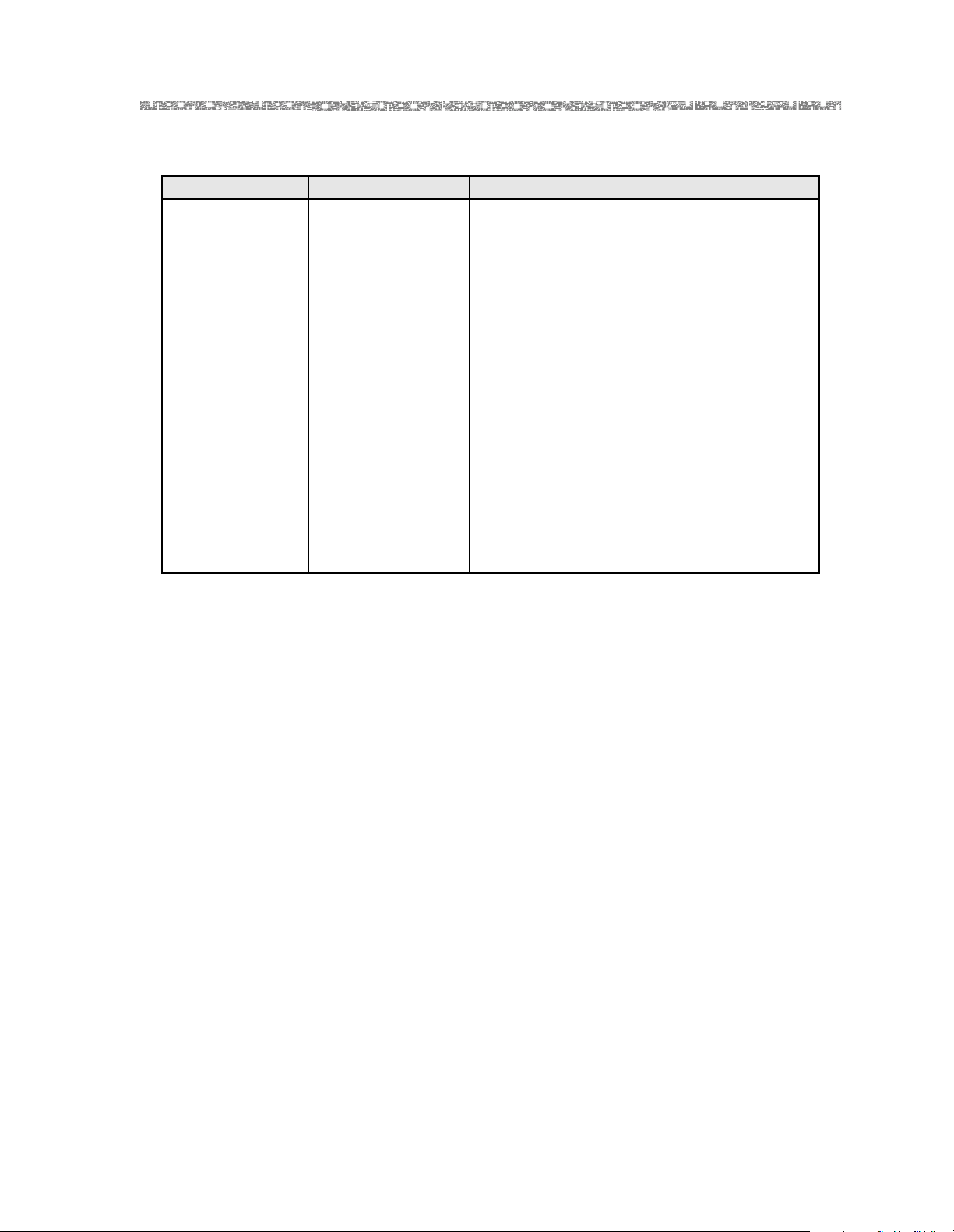
Chapter 6 Configuring Ports and Channels Using the Console Interface
DSP2C Through DSP2F Channel Configuration
Table 6-5. Field Descriptions for the DSP2C Through DSP2F Channel and Interface Configuration
Window
Field Name Field Values Description
DSP Mode
The options
described for
AlgoSet5 are available only on the
DSP2D module;
options are display
only on the Software Release 6.5
DSP2A and DSP2B
Single-Algoset
modules.
AlgoSet5
(This algoset is the
default for the DSP2D
module)
Note: This mode is
not available on the
DSP2C/E/F modules.
Displays Algorithm Set 5 with this voice process-
ing feature:
G168-echo-cancellation64ms
This [Algorithm Type] field displays by default on
the left panel of the window before and after
configuration. Use this algoset with AAL1 Mode,
selectable in the AAL Mode field in the right
panel of this window.
This mode provides 21 connections per channel
for a total of 1008 CE-to-CE connections per
DSP2D module.
Select this mode for up to 1008 connections on
the GR-303 interface. GR-303 scanning is not
applicable in this mode.
To change from one DSP mode to another after
selecting the Apply Channel Configuration
command, first delete the channel (from the
DSP2D Port Configuration window), then select
and apply another DSP mode configuration.
PacketStar® DSP2x Voice Server Modules User Guide, Issue 1 Release 8.0.0
255-700-251 6-15
Page 90

Chapter 6 Configuring Ports and Channels Using the Console Interface
DSP2C Through DSP2F Channel Configuration
Table 6-5. Field Descriptions for the DSP2C Through DSP2F Channel and Interface Configuration
Window
Field Name Field Values Description
DSP Mode AlgoSet6
(This algoset is the
default for the DSP2E
module)
Displays Algorithm Set 6 with these voice and
data processing features:
On the DSP2E module, if you select this algoset,
these features appear in the Algorithm Type
field:
Note: Algoset6 is not
available on the
DSP2AB/C modules.
G726-voice-compression
G729a-voice-compression
G729b-silence-suppression
G168-echo-cancellation64ms
V17-fax-algorithm-upto-14400-bps
V29-fax-algorithm-upto-9600-bps
V27ter-fax-algorithm-upto-2400-bps
V21-fax-algorithm-upto-300-bps
On the DSP2E module, only Algoset6 can be
configured on DSP Channels 1 through 6. DSP
channels 7 and 8 must use AlgoSet7. Use
Algoset6 with standard AAL2 (selectable in the
AAL Mode field on the right panel of this window).
Select Algoset6 for PacketPipe AAL5-to-AAL2
Trunking on the HDLC interface on a VBR-toATM connection on the DSP2D module. This
mode provides not more than 96 connections per
module.
If you are using the DSP2D module in a GR-303
interface, select this mode to support 384 AAL2
trunk groups. This mode also provides the capacity for 1152 connections to be scanned for talking
or data paths to be set up as needed.
DSP Mode AlgoSet 7
(This algoset is the
default for the DSP2F
module)
Note: AlgoSet7 is not
available on the
DSP2A through
DSP2D modules, or
DSP chips 1 through
6 of the DSP2E module.
Displays Algorithm Set 7 with this voice processing feature:
Hdlc-on-I366-1-AAL2-frame-mode
AlgoSet7 is configurable only on DSP Channels
7 and 8 on the DSP2E module.
Select AlgoSet7 for wireless applications using
the HDLC interface on a VBR-to-ATM connection. AlgoSet7 supports Std I.366 and AAL2
Frame mode. If you select this value, the feature
set listed above appears after the [Algorithm
Type] display-only field (the lower left panel on
the Port Configuration window).
PacketStar® DSP2x Voice Server Modules User Guide, Issue 1 Release 8.0.0
6-16 255-700-251
Page 91

Chapter 6 Configuring Ports and Channels Using the Console Interface
DSP2C Through DSP2F Channel Configuration
Table 6-5. Field Descriptions for the DSP2C Through DSP2F Channel and Interface Configuration
Window
Field Name Field Values Description
[Alarm Status]
(display only)
Default: NoAlarm
Range: N/A
Indicates whether module is operating normally
or not.
Format: Predefined
NoAlarm Indicates normal operating status.
DSP Failure Indicates DSP failure. See the Note at the end of
this table.
[Oper. Status]
(display only)
Default: OutOfSer-
vice
Indicates whether the module is operational or
not according to the administrative status.
Range: N/A
Format: Predefined
InService Indicates that the interface is operational.
OutOfService Indicates that the interface is not operational.
[Admin. Status]
(display only)
Default: InService
Range: N/A
Indicates that no administrative conditions are
preventing the port from being fully operational.
Format: Predefined
InService Indicates that no administrative conditions are
preventing the port from being fully operational.
OutOfService Indicates that some condition is preventing the
port from being administratively in service.
[Load Count]
(display only)
Default: 0
Range: Module
Displays the number of connections currently
assigned to an individual DSP processor.
Dependent
Format: Numeric
PacketStar® DSP2x Voice Server Modules User Guide, Issue 1 Release 8.0.0
255-700-251 6-17
Page 92

Chapter 6 Configuring Ports and Channels Using the Console Interface
DSP2C Through DSP2F Channel Configuration
Table 6-5. Field Descriptions for the DSP2C Through DSP2F Channel and Interface Configuration
Window
Field Name Field Values Description
AAL Mode
The options
described for this
field are only available on the DSP2C
module; options are
display only on the
DSP2A and DSP2B
modules.
Default: Vari able
Aal1
Range: N/A
Format: Predefined
Aal2-non-multiplexed
(This mode is the
default for the
DSP2C module)
Aal2-standard
(This mode is the
default for the
DSP2D module),
DSP2E, and DSP2F
module(s))
Indicates no multiplexing used.
Indicates AAL2 with no multiplexing (uncompressed CBR).
Indicates standard AAL2. On the DSP2C, a maximum of 64 trunk groups may be multiplexed in
any combination of AlgoSets 1 through 4.
On the DSP2D, a maximum of 336 trunk groups
may be multiplexed using AlgoSet 1. A maximum of 384 trunk groups may be multiplexed
using AlgoSet 6.
On the DSP2E and DSP2F, only standard AAL2 is
available.
This mode must be selected when using:
• Fax relay mode (AlgoSet4) on the DSP2C
• GR-303 interface feature
• Switched VToA narrowband trunking
• HDLC interface on a VBR-to-ATM connection
for wireless applications.
Note: In Release 7.1 and higher, if a DSP chip (channel) fails, the host pro-
cessor in the DSP2C/D modules will attempt to reboot the chip
(channel) for seven consecutive times. If unable to reboot, the chip is
classified as failed and the CPU will not use it again (you may view
the status of all DSPs on the DSP Resource Table, accessible through
the Site-Specific Menu by using the DSP Resource Configuration
command). Any failures will also display in the [Alarm Status] field
in theleft panel of the Channel and Interface configuration window
when the failed chip (channel) number is entered in the DSP: field in
the upper left panel of the same window
6 On the DSP2D Channel and Interface Configuration window, select the
desired DSP Mode by pressing Enter until the desired AlgoSet is displayed. The applied configuration example shown in Figure 6-11 is
AlgoSet5.
7 In the AAL Mode field, leave the default Aal1 as is. (For DSP2D configu-
ration, this is the only mode available in System Software Release 7.0).
8 Select Apply Channel Configuration and press Enter (or press Ctrl+A).
9 Select Bring Interface Into Service, and press Enter (or press Ctrl+N).
PacketStar® DSP2x Voice Server Modules User Guide, Issue 1 Release 8.0.0
6-18 255-700-251
Page 93

Chapter 6 Configuring Ports and Channels Using the Console Interface
DSP2C Through DSP2F Channel Configuration
At this point, if the commands were successful, the console status message line will display:
T-InterfaceInService: interfaceIndex=801003 interfaceType=DSP2
The message format of the interfaceIndex number is: slot-slot-port-portchannel-channel-channel format. This message tells you that the interface-
Index has recorded the DSP2 module in slot 8, port 01, channel 003 as
ready for service.
At this point, you may see the channel configuration applied and in service by returning to the port configuration window. Select Go Back to
Port Configuration and press Enter (or press Ctrl+B) to view the Port
Configuration window (see Figure 6-11), displaying AlgoSet5 in the
lower left panel. The configured channel you selected will display as
InService.
Figure 6-11. DSP2D Channel /Interface 1 with AlgoSet 5 InService (G169-echo-
cancellation64ms) Displaying on Lower Left Panel
10 At this point, you may configure all the interfaces by selecting Config-
ure All Interfaces On This Port and pressing Enter (or press Ctrl+N). All
interfaces will display Out of Service and have the same configuration
as Channel 1.
11 Select Bring All Interfaces Into Service and press Enter (or press
Ctrl+N). Interfaces will display In Service. All interfaces on your DSP2D
module are now configured as AlgoSet5.
End
PacketStar® DSP2x Voice Server Modules User Guide, Issue 1 Release 8.0.0
255-700-251 6-19
Page 94

Chapter 6 Configuring Ports and Channels Using the Console Interface
DSP2C Through DSP2F Channel Configuration
Changing Single DSP Channel Modes on the DSP2C Voice Server Module
Use the following procedure if you need to change a few channels to
AlgoSet4 (fax relay mode), and leave the rest of the channels on the module
in AlgoSets 1, 2, or 3.
Taking Single DSP Channels Out of Service After Bringing All
Interfaces Into Service on the DSP2C Voice Server Module
Begin
1 On the DSP2C Port Configuration window, select the interface to be
taken out of service and press Enter. The Port and Interface Configuration window is displayed.
2 Press the Take Interface Out of Service Command (or press Ctrl+N).
The status line displays this message:
Taking the interface down will cause all SVCs to be lost. Continue:
(y/n)
3 Press y for yes. The interface is deleted and this message displays on the
status line:
T-InterfaceOutOfService: interfaceIndex=801047 interfaceType=Dsp2
This message confirms that channel 047 is now out of service.
4 Press the Delete This Interface command (or press Ctrl+D). The status
line prompts:
Are you SURE you want to delete this interface? (y/n)
5 Press y for yes. The Port Configuration window is displayed. The chan-
nel you just deleted will be selected by dafault and will display Uncon-
figured.
6 Press Enter. The status line prompts:
Unconfigured. Configure interface now? (y/n)
7 Press y for yes. The Channel and Interface Configuration window is dis-
played.
8 Select the DSP Mode field and press Enter until the desired AlgoSet
mode is displayed.
9 Select the AAL Mode field and press Enter until the desired AAL mode
is displayed.
10 Press the Apply Channel Configuration command (or press Ctrl+A).
The stauts line reports:
The configuration has been applied.
11 Press the Bring Interface Into Service command (or press Ctrl+N). the
status line confirms the new channel interface is in service.
PacketStar® DSP2x Voice Server Modules User Guide, Issue 1 Release 8.0.0
6-20 255-700-251
Page 95

Chapter 6 Configuring Ports and Channels Using the Console Interface
d
DSP2C Through DSP2F Channel Configuration
At this point, if you return to the Port Configuration window, the channel status will now display the new AlgoSet Mode, and the lower left
panel will display the AlgoSet parameters.
Use this procedure to change the channel AlgoSet mode configuration
on as many channels as you need.
En
You may also take a channel out of service on the Channel and Interface
Configuration window. To do so, perform the following procedure:
Taking a Channel Out of Service on the Channel and Interface
Configuration Window
Begin
1 In the upper left panel of the DSP2x Channel and Interface Configura-
tion window, use the arrow key to select the DSP: field.
2 Press Enter to start edit mode (the black background of the field disap-
pears).
3 Enter the channel number of the channel you want to take out of ser-
vice in the DSP: field.
4 You must press Enter to exit edit mode on the field.
5 Press the Take Interface Out of Service command (or press Ctrl+N).
The console status line will display the OutofService message.
End
Changing the Entire Module From One DSP Mode to a Different DSP
Mode
Begin
Note: This procedure changes all interfaces on a module from one DSP
mode to another mode. This procedure will change AlgoSet2 to
AlgoSet3.
1 On the DSP2C Port Configuration window, select Take All Interfaces
Out of Service and press Enter (or press Ctrl+N). The screen prompts:
Are you sure you want to take ALL interfaces out of service?
(y/n)
2 Select y.
The status line displays a message declaring all interfaces out of service.
3 Select the Delete All Interfaces On This Port command and press Enter
(or press Ctrl+D). The status line prompts:
Are you sure you want to delete ALL interfaces for this
port? (y/n)
PacketStar® DSP2x Voice Server Modules User Guide, Issue 1 Release 8.0.0
255-700-251 6-21
Page 96

Chapter 6 Configuring Ports and Channels Using the Console Interface
Configuring the DSP2A or DSP2B Single-AlgoSet Voice Server Modules (Release 6.2.0)
4 Select y for yes The status displays:
T-InterfaceDeleted: interfaceIndex: 801001 [sample value]
5 Select a channel and press Enter. The status line prompts:
Unconfigured. Configure interface now? (y/n)
6 Press y for yes. The Channel and Interface Configuration window is dis-
played.
7 Select the DSP Mode you desire (AlgoSet3 in this example) and press
the Apply Channel Configuration command. The status line reports:
The configuration has been applied.
8 Return to the Port Configuration window using the Go Back to Port
Configuration command (or press Ctrl+B). The Port Configuration
window is displayed.
9 The channel you configured in Step 5 will be selected by default. Press
the Configure All Interfaces On This Port command (or press Ctrl+C).
10 All channels display the OutofService status.
11 Press the Bring all Interfaces Into Service command (or press Ctrl+N).
All channels display InService status. The lower left panel displays the
new AlgoSet you have applied to all channels.
Configuring the DSP2A or DSP2B Single-AlgoSet Voice
Server Modules (Release 6.2.0)
!
CAUTION:
These modules are not the DSP2A or DSP2B modes that are emulated on
the DSP2C Voice Server module. These modules are not upgradeable to
all System Software Releases 6.3.0 and beyond.
Configuring All Interfaces on the DSP2A or DSP2B Module
Simultaneously (Single-AlgoSet DSP2A or DSP2B Modules Only)
Begin
1 On the DSP2A or DSP2B Port Configuration window, (see Figure 6-12
on page 6-23), select Configure All Interfaces On This Port and press
Enter (or press Ctrl+C). (This example selects the DSP2A module).
2 At the screen prompt, select y for yes.
3 Select Bring All Interfaces Into Service and press Enter (or press
Ctrl+N). All interfaces display In Service.
End
PacketStar® DSP2x Voice Server Modules User Guide, Issue 1 Release 8.0.0
6-22 255-700-251
Page 97

Chapter 6 Configuring Ports and Channels Using the Console Interface
Configuring the DSP2A or DSP2B Single-AlgoSet Voice Server Modules (Release 6.2.0)
Configuring the DSP2A or DSP2B Module Interfaces Individually
(Single-AlgoSet Modules Only)
Begin
1 On the DSP2A or DSP2B Port Configuration window, (Figure 3-7
shows the DSP2A window) select an interface and press Enter.
The Channel and Interface Configuration window is displayed (for the
DSP2A module)(see Figure 3-8).
Note: The DSP2 mode is display only.
Figure 6-12. Single-AlgoSet DSP2A Port Configuration Window (Before
Configuration)
The commands on this window have the following functions:
Commands
PacketStar® DSP2x Voice Server Modules User Guide, Issue 1 Release 8.0.0
255-700-251 6-23
Page 98
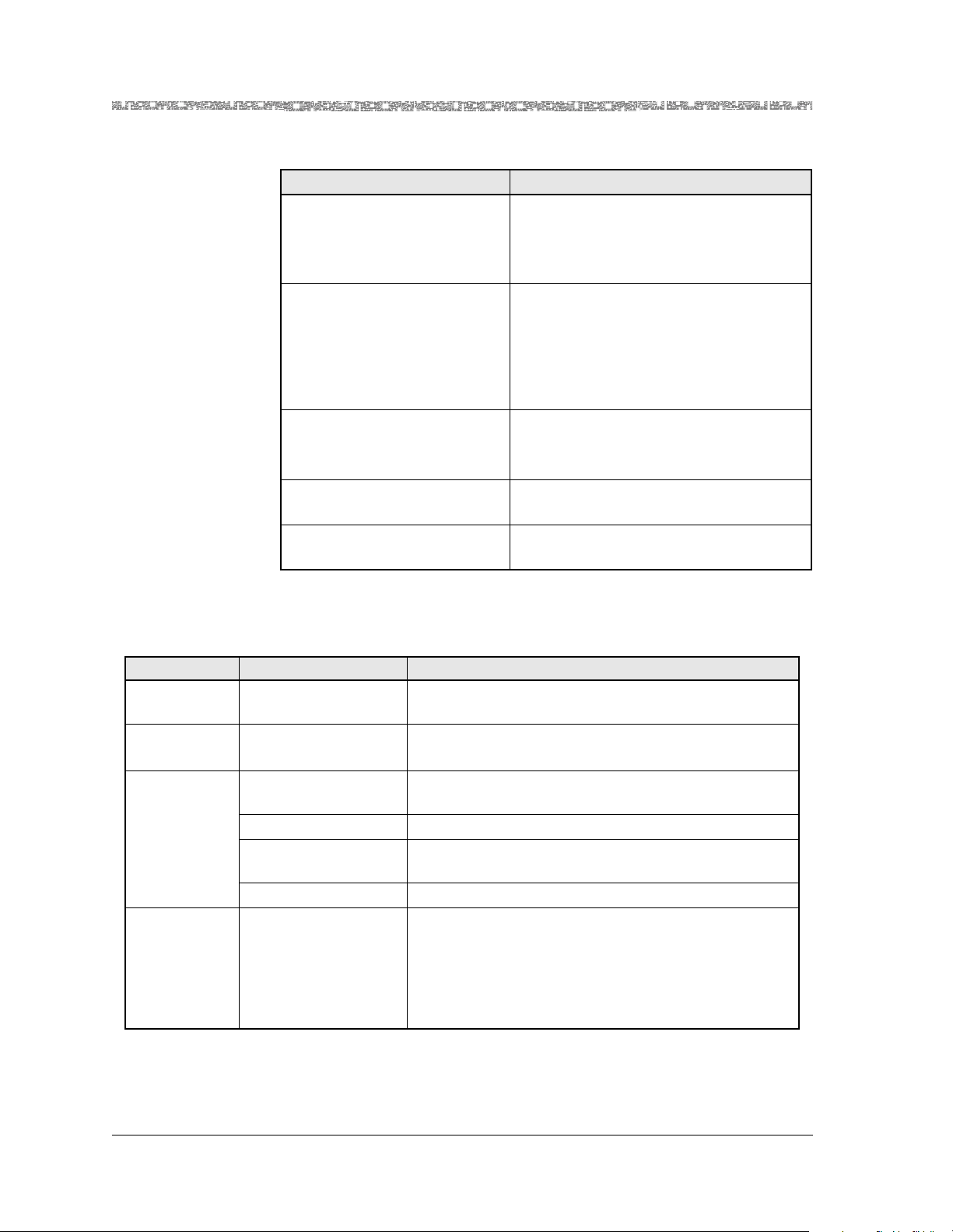
Chapter 6 Configuring Ports and Channels Using the Console Interface
Configuring the DSP2A or DSP2B Single-AlgoSet Voice Server Modules (Release 6.2.0)
Table 6-6.
Command Function
Configure All Interfaces On
This Port
Configures all DSP interfaces for this port.
If the first DSP interface is configured, this
command will configure the remaining
interfaces the same way.
Delete All Interfaces On
This Port
Deletes all out-of-service configured interfaces.
You must first take all interfaces out of
service (using the Take All Interfaces
Out Of Service command) before you
can use this command.
Bring All Interfaces Into
Service
Brings the out-of-service configured interfaces to in-service status.
Note:
Take All Interfaces Out of
Service
Go Back to Equipment Configuration
Takes the in-service configured interfaces
to out-of-service status.
Redisplays the Equipment Configuration
window.
2 Select the values for this window from Table 6-7.
Table 6-7. Field Descriptions for the DSP2A/B/C Port Configuration Window
Field Name Field Values Description
Slot: Range: Varies depend-
The slot containing the DSP2C Voice Server module.
ing on chassis type
[Port:]
(display only)
DSP Admin
Status
Default: 01
Range: 1
Range: 1 – 32
(channels)
The port of the DSP2A or B Voice Server module.
32 chips (channels) on the modules
Unconfigured Interface available for configuration
InService Interface configured. Right panel of window will show
configuration type.
OutOfService Interface is not available; user selected.
[Algorithm
Type]
Default: AlgoSet2,
(default on DSP2A
module)
Default: AlgoSet3,
The default value indicates that the interface is unconfigured. After a DSP mode is applied on the Channel
and Interface Configuration window, the algorithm
parameters display in the right panel of this window.
(default on DSP2B
module)
3 Select a channel and press Enter.
The Status Line prompts: Interface unconfigured. Configure now?
PacketStar® DSP2x Voice Server Modules User Guide, Issue 1 Release 8.0.0
6-24 255-700-251
Page 99

Chapter 6 Configuring Ports and Channels Using the Console Interface
Configuring the DSP2A or DSP2B Single-AlgoSet Voice Server Modules (Release 6.2.0)
4 Select y for yes.
The DSP2A Channel and Interface Configuration window is displayed,
as shown in Figure 6-13.
.
Figure 6-13. Channel and Interface Configuration Window for AlgoSet2 (Single-
AlgoSet DSP2A Module)
Commands The commands on this screen have the following functions:
Table 6-8. DSP2A Channel and Interface Window Commands
Command Function
Bring Interface Into Service Brings the interface into service for what-
ever configuration was applied.
Delete Interface and Return Deletes the interface and redisplays the
previous window.
Go Back to Port Configura-
Redisplays the port configuration window.
tion
5 Select Bring Interface Into Service and press Enter (or press Ctrl+N).
See the status line in Figure 6-13 for the channel, port and slot in-service message.
If you return to the DSP2A Port Configuration Window, the channel is
displayed, showing the configured interface as OutOfService with
AlgoSet2 applied (see Figure 6-14).
PacketStar® DSP2x Voice Server Modules User Guide, Issue 1 Release 8.0.0
255-700-251 6-25
Page 100

Chapter 6 Configuring Ports and Channels Using the Console Interface
d
Saving the Equipment Configuration and Logging Off
Figure 6-14. DSP2A Single-AlgoSet Module Port Configuration Window (After
Configuration)
6 To configure remaining interfaces into service, select Configure All
Interfaces On This Port and press Enter (or press Ctrl+C). All interfaces
will display as Out of Service.
7 Select Bring All Interfaces Into Service and press Enter (or press
Ctrl+N). All Interfaces display as In Service.
En
Saving the Equipment Configuration and Logging Off
After configuring the module ports and channels, the interface types for each
port and channel, and the connections, you must save the values to the
PSAX system database. It is recommended that you save your values frequently as you progress through your work, at a minimum, after finishing
each stage of work:
• Configuring each module in your system
• Configuring the connections in your system
• Before exiting your current console session
Perform the following procedure to permanently save the values for your
system.
PacketStar® DSP2x Voice Server Modules User Guide, Issue 1 Release 8.0.0
6-26 255-700-251
 Loading...