

Page 1

PacketStar
®
PSAX 4-Port Voice 2-Wire Office Module
User Guide
Model 20N32
®
for the PacketStar
Issue 1, October 2003
System Software Release 9.0.0
®
Navis
AQueView
PSAX Multiservice Media Gateways
®
EMS Software Release 9.0.0
Doc. No.: 255-700-467
Page 2

Copyright © 2003 by Lucent T echnologies. All rights reserved.
For trademark, regulatory compliance, and related legal information, see
the "Legal Notices, Safety, and Regulatory Information" section.
Page 3

Legal Notices, Safety, and Regulatory
Copyright
Tra demarks
Information
Copyright © 2003 by Lucent T echnologies. All rights reserved.
This material is protected by the copyright laws of the United States and
other countries. It may not be reproduced, distributed, or altered in any fashion by any entity (either internal or external to Lucent Technologies), except
in accordance with applicab le agreements , contracts o r licensing, wi thout the
express written consent of the originating organization and the business
management owner of the material.
This document was prepared by the Information Design and Development
T eam of Lucent Technologies, PacketStar PSAX products. O ffices are loc ated in
Landover, Maryland, USA.
PacketStar, AQueView, Lucent, Lucent Technologies, and the Lucent Technologies logo are register ed tradema rks of Lucent Technologies in the USA. Other
product and brand names mentioned in this guide are trademarks or registered trademarks of their respective owners.
Notices
The information in this document is for informational use only, is subject to
change without notice, and should not be construed as a commitment by
Lucent Technologies, Inc. This document is without warranty of any kind,
either expressed or implied. Lucent Technologies, Inc. assumes no responsibility for any errors, inaccuracies, or omissions. Neither is any liability
assumed for damages resulting from the use of the information or instructions contained herein. Lucent Technologies, Inc. is not responsible for any
damage or loss to your data or equipment resulting either directly or indirectly from use of this document.
Warranty Information
Software and Hardware Limited Warranties
Lucent Technologies provides a 90-day limited software warranty, and a oneyear limited hardware warranty on this product. Refer to the Software License
and Limited Warranty Agreement and the Lucent Technologies InterNetworking Systems Global Warranty that accompanied your package for more information.
PacketStar® PSAX 4-Port Voice 2-Wire Office Module User Guide, Issue1 Release9.0.0
255-700-467 iii
Page 4

Legal Notices, Safety, and Regulatory Information
Safety Information
Warr anty Warnings
!
WARNING:
When inserting modules into the chassis, slide them gently, not forcefully. Excessive force may cause the modules to be seated improperly in
the chassis, and result in possible damage to the module or the chassis.
Install or remove modules one at a time. Doing this aids in preventing
the PSAX system from indicating any erroneous failure messages, and
allows the PSAX system time to reinitialize and display the accurate configuration of the module that is inserted.
!
CAUTION:
Modifying or tampering with PSAX chassis components may void your
warranty. Any modification to this equipment not expressly authorized
by Lucent Technologies may void your granted authority to operate such
equipment.
!
CAUTION:
Shipping the chassis with removable I/O, server, or CPU modules
installed may cause damage to the chassis and the modules. Damage to
any of the components in the system resulting from shipping the chassis
with removable modules installed will void your warranty.
!
DANGER:
Interface lines connected to the 4-Port Voice 2-Wire Office module
(model 20N32) that exit the building premises must be connected to telecommunication devices that provide primary and secondary protection.
Safety Information
When installing and operating the 4-Port Voice 2-W ire Office module, follow
the safety guidelines provided in the PacketStar
way Safety Guidelines, which accompanies this product, to help prevent serious
personal injury and damage to the module. Please read all warnings and
instructions supplied before beginning installation or configuration of this
module. In addition to the general safety information provided, you should
also refer to the text in the PacketStar PSAX installation guides for other
important safety information and procedures.
Regulatory Standards Compliance
Safety and Electromagnetic Compatibility (EMC)
The following PacketStar PSAX systems are compliant with applicable safety
and EMC standards when configured with the 4-Port Voice 2-Wire Office
module (model 20N32):
®
PSAX Multiservice Media Gate-
PacketStar® PSAX 4-Port Voice 2-Wire Office Module User Guide, Issue 1 Release 9.0.0
iv 255-700-467
Page 5

• PSAX 1000 system
• PSAX 1250 system
• PSAX 2300 system
• PSAX 4500 system
Please refer to the PacketStar PSAX 1000, PSAX 1250, PSAX 2300, or
PSAX 4500 Multiservice Media Gateway installation guide for details on
safety and EMC standards compliance.
Telecommunications
• FCC Part 68 (USA)
• CS-03 Issue 8 (Canada)
Regulatory Statements
USA Regulatory State ments
Legal Notices, Safety, and Regulatory Information
Regulatory Statements
FCC Part 68 This equipment complies with Part 68 of the FCC rules. On the back of the
PSAX chassis is a label that contains the FCC registration number, in addition
to other information. You must provide this information to the telephone
company, if they request it. The FCC requires Lucent Technologies to provide
you with the following information:
1. This equipment has digital service interface capabilities using RJ-48C and
RJ-48H connectors. The facility interface codes with which this equipment complies for digital services are as follows: 04DU9-BN, 04DU9-DN,
04DU9-1KN, and 04DU9-1SN. This equipment has loop start interface
capabilities using an RJ-11C connector. The facility interface code with
which this equipment complies for service is 02LS2. The service order
codes for this equipment are 6.0F for the T1 interface and 9.0Y for the
loop start interface.
2. An FCC-compliant telephone network interface jack is built into this
equipment and is compatible with interconnections that are Part 68
compliant.
3. The REN for the 4-Port Voice 2-Wire Office module when used in this
equipment is 0.7B.
4. If this equipment causes harm to the telephone network, the telephone
company will notify you in advance that temporary discontinuance of
service might be required. But if advance notice is not practical, the telephone company will notify you as soon as possible. Also, you will be
advised of your right to file a complaint with the FCC if you believe this
is necessary.
5. The telephone company might make changes in its facilities, equipment,
operations, or procedures that could affect the operation of this equipment. If this happens, the telephone company will provide advance
notice for you to make necessary modifications to maintain uninterrupted service.
PacketStar® PSAX 4-Port Voice 2-Wire Office Module User Guide, Issue1 Release9.0.0
255-700-467 v
Page 6

Legal Notices, Safety, and Regulatory Information
Regulatory Statements
6. If you experience trouble with this equipment, or need repairs or warranty information, please refer to the Lucent Technologies InterNetworking
Systems G lobal Warranty that accompanied your PSAX product shipment
for instructions on obtaining technical support in your area.
If this equipment is causing harm to the telephone network, the telephone company might request that you disconnect the equipment until
the problem is resolved.
7. This equipment has no user-serviceable parts.
This equipment cannot be used on public coin telephone service provided by
the telephone company. Connection to party line service is subject to state
tariffs. Contact your state public utility commission, public service commission, or corporation commission for information.
Canadian Regulatory Statements
CS-03 Issue 8 NOTICE: This eq uipment meets applicable Industry Canada Termi-
nal Equipment Technical Specifi cati ons. Thi s is conf irme d by the reg istration number. The abbreviation, IC, before the registration number signifies that registration was performed based on a Declaration
of Conformity indicating that Industry Canada technical specifications were met. It does not imply that Industry Canada approved the
equipment.
The Ringer Equivalence Number (REN) assigned to the 4-Port Voice 2-Wire
Office module denotes the percentage of the total load to be connected to a
telephone loop, which is used by the device, to prevent overloading. The termination on a loop may c onsist of any combinat ion of dev ices subj ect only to
the requirement that the t otal of the REN of all devices does not exceed 5.
The REN for the 4-Port Voice 2-Wire Office module when used in the PSAX
system is 0.7B.
SH-03 Version 8 A VIS: Le présent matériel est conforme aux spécifications techniques
d’Industrie Canada applicables au matériel terminal. Cette conformité est confirmée par le numéro d’enregistrement. Le sigle, IC,
placé devant le numéro d’enregistrement, signifie que l’enregistrement s’est ef fectué conformément à une déclaration de conformité
et indique que les spécifications techniques d’Industrie Canada ont
été respectées. Il n’implique pas qu’Industrie Canada a approuvé le
matériel.
Le nombre équivalent de sonnerie (REN) attr ibué au module cen tral bifilaire
(Voice 2-Wire Office) correspond au pourcentage de la charge totale à connecter à un circuit téléphonique bifilaire; il est utilisé par l’appareil pour
prévenir la surcharge. Le circuit peut être terminé par n’importe quelle combinaison d’appareils, à la seule condition que le total des REN de ces derniers
ne dépasse pas cinq.
Lorsqu’il est utilisé dans le système PSAX, le module central bifilaire possède
un REN de 0,7 B.
PacketStar® PSAX 4-Port Voice 2-Wire Office Module User Guide, Issue 1 Release 9.0.0
vi 255-700-467
Page 7

Legal Notices, Safety, and Regulatory Information
Regulatory Statements
PacketStar® PSAX 4-Port Voice 2-Wire Office Module User Guide, Issue1 Release9.0.0
255-700-467 vii
Page 8

Legal Notices, Safety, and Regulatory Information
Regulatory Statements
PacketStar® PSAX 4-Port Voice 2-Wire Office Module User Guide, Issue 1 Release 9.0.0
viii 255-700-467
Page 9

Contents
Legal Notices, Safety, and Regulatory Information . . . . . . . . . . . . . . . . . iii
Copyright . . . . . . . . . . . . . . . . . . . . . . . . . . . . . . . . . . . . . . . . . . . . . . . . . . . . . . . . . . . . . iii
Trademarks . . . . . . . . . . . . . . . . . . . . . . . . . . . . . . . . . . . . . . . . . . . . . . . . . . . . . . . . . . . . iii
Notices . . . . . . . . . . . . . . . . . . . . . . . . . . . . . . . . . . . . . . . . . . . . . . . . . . . . . . . . . . . . . . . iii
Warranty Information . . . . . . . . . . . . . . . . . . . . . . . . . . . . . . . . . . . . . . . . . . . . . . . . . . . . . iii
Software and Hardware Limited Warranties . . . . . . . . . . . . . . . . . . . . . . . . . . . . . . . . . iii
Warranty Warnings . . . . . . . . . . . . . . . . . . . . . . . . . . . . . . . . . . . . . . . . . . . . . . . . . . . iv
Safety Information . . . . . . . . . . . . . . . . . . . . . . . . . . . . . . . . . . . . . . . . . . . . . . . . . . . . . . .iv
Regulatory Standards Compliance . . . . . . . . . . . . . . . . . . . . . . . . . . . . . . . . . . . . . . . . . . . iv
Safety and Electromagnetic Compatibility (EMC) . . . . . . . . . . . . . . . . . . . . . . . . . . . . . iv
Telecommunications . . . . . . . . . . . . . . . . . . . . . . . . . . . . . . . . . . . . . . . . . . . . . . . . . . v
Regulatory Statements . . . . . . . . . . . . . . . . . . . . . . . . . . . . . . . . . . . . . . . . . . . . . . . . . . . . v
USA Regulatory Statements . . . . . . . . . . . . . . . . . . . . . . . . . . . . . . . . . . . . . . . . . . . . . v
FCC Part 68 . . . . . . . . . . . . . . . . . . . . . . . . . . . . . . . . . . . . . . . . . . . . . . . . . . . . . v
Canadian Regulatory Statements . . . . . . . . . . . . . . . . . . . . . . . . . . . . . . . . . . . . . . . . . vi
CS-03 Issue 8 . . . . . . . . . . . . . . . . . . . . . . . . . . . . . . . . . . . . . . . . . . . . . . . . . . . . vi
SH-03 Version 8 . . . . . . . . . . . . . . . . . . . . . . . . . . . . . . . . . . . . . . . . . . . . . . . . . . vi
iii
.iv
iii
iii
iii
iii
iii
iv
iv
iv
v
v
v
v
vi
vi
vi
List of Figures . . . . . . . . . . . . . . . . . . . . . . . . . . . . . . . . . . . . . . . . . . . . . . xiii
List of Tables . . . . . . . . . . . . . . . . . . . . . . . . . . . . . . . . . . . . . . . . . . . . . . . xiv
1 Getting Started . . . . . . . . . . . . . . . . . . . . . . . . . . . . . . . . . . . . . . . . . . . . . . . . 1-1
Purpose of This Guide . . . . . . . . . . . . . . . . . . . . . . . . . . . . . . . . . . . . . . . . . . . . . . . . . . . .1-1
Audience for This Guide . . . . . . . . . . . . . . . . . . . . . . . . . . . . . . . . . . . . . . . . . . . . . . . . . .1-1
What You Should Know . . . . . . . . . . . . . . . . . . . . . . . . . . . . . . . . . . . . . . . . . . . . . . . . . .1-1
Related Reading . . . . . . . . . . . . . . . . . . . . . . . . . . . . . . . . . . . . . . . . . . . . . . . . . . . . . . . .1-2
Lucent Technologies Information Products . . . . . . . . . . . . . . . . . . . . . . . . . . . . . . . . .1-2
Product Information Library . . . . . . . . . . . . . . . . . . . . . . . . . . . . . . . . . . . . . . . . .1-2
Printed Documents. . . . . . . . . . . . . . . . . . . . . . . . . . . . . . . . . . . . . . . . . . . . . . . .1-2
Other Publications . . . . . . . . . . . . . . . . . . . . . . . . . . . . . . . . . . . . . . . . . . . . . . . . . . .1-2
About Lucent Technologies . . . . . . . . . . . . . . . . . . . . . . . . . . . . . . . . . . . . . . . . . . . . . . . .1-2
About the PacketStar PSAX Product Family . . . . . . . . . . . . . . . . . . . . . . . . . . . . . . . . . . . .1-3
PSAX 1000 Multiservice Media Gateway. . . . . . . . . . . . . . . . . . . . . . . . . . . . . . . . . . .1-3
PacketStar® PSAX 4-Port Voice 2-Wire Office Module User Guide, Issue 1 Release 9.0.0
255-700-467 ix
xiii
xiv
1-1
.1-1
.1-1
.1-1
.1-2
.1-2
.1-2
.1-2
.1-2
.1-2
.1-3
.1-3
Page 10

Contents
PSAX 1250 Multiservice Media Gateway . . . . . . . . . . . . . . . . . . . . . . . . . . . . . . . . . . 1-3
PSAX 2300 Multiservice Media Gateway . . . . . . . . . . . . . . . . . . . . . . . . . . . . . . . . . . 1-4
PSAX 4500 Multiservice Media Gateway . . . . . . . . . . . . . . . . . . . . . . . . . . . . . . . . . . 1-4
Document Conventions . . . . . . . . . . . . . . . . . . . . . . . . . . . . . . . . . . . . . . . . . . . . . . . . . . 1-5
Text Types Used in This Document . . . . . . . . . . . . . . . . . . . . . . . . . . . . . . . . . . . . . . . 1-5
Icons and Symbols . . . . . . . . . . . . . . . . . . . . . . . . . . . . . . . . . . . . . . . . . . . . . . . . . . 1-5
Use of Command Description Tables . . . . . . . . . . . . . . . . . . . . . . . . . . . . . . . . . . . . . 1-6
Use of Field Description Tables. . . . . . . . . . . . . . . . . . . . . . . . . . . . . . . . . . . . . . . . . . 1-6
General Document Navigational Guidelines . . . . . . . . . . . . . . . . . . . . . . . . . . . . . . . . . . . 1-7
Selecting Options, Fields, and Commands Using the Console Interface . . . . . . . . . . . 1-7
Selecting Menu Options and Fields in the AQueView GUI . . . . . . . . . . . . . . . . . . . . . 1-8
Help Information . . . . . . . . . . . . . . . . . . . . . . . . . . . . . . . . . . . . . . . . . . . . . . . . . . . . . . 1-10
Technical Support . . . . . . . . . . . . . . . . . . . . . . . . . . . . . . . . . . . . . . . . . . . . . . . . . . . . . 1-11
Before You Begin. . . . . . . . . . . . . . . . . . . . . . . . . . . . . . . . . . . . . . . . . . . . . . . . . . . . . . 1-12
Comments on This Guide . . . . . . . . . . . . . . . . . . . . . . . . . . . . . . . . . . . . . . . . . . . . . . . 1-12
2 Module Description . . . . . . . . . . . . . . . . . . . . . . . . . . . . . . . . . . . . . . . . . . . . .2-1
Overview of This Chapter . . . . . . . . . . . . . . . . . . . . . . . . . . . . . . . . . . . . . . . . . . . . . . . . 2-1
4-Port Voice 2-Wire Office Module . . . . . . . . . . . . . . . . . . . . . . . . . . . . . . . . . . . . . . . . . 2-2
Module Placement Requirements. . . . . . . . . . . . . . . . . . . . . . . . . . . . . . . . . . . . . . . . . . . 2-2
Hardware Features. . . . . . . . . . . . . . . . . . . . . . . . . . . . . . . . . . . . . . . . . . . . . . . . . . . . . . 2-2
General Hardware Specifications . . . . . . . . . . . . . . . . . . . . . . . . . . . . . . . . . . . . . . . . . . . 2-2
Chassis Speed, Power Consumption, and Memory Allocation . . . . . . . . . . . . . . . . . . . . . 2-3
LED Indicators . . . . . . . . . . . . . . . . . . . . . . . . . . . . . . . . . . . . . . . . . . . . . . . . . . . . . . . . . 2-3
1-3
1-4
1-4
1-5
1-5
1-5
1-6
1-6
1-7
1-7
1-8
1-10
1-11
1-12
1-12
2-1
2-1
2-2
2-2
2-2
2-2
2-3
2-3
3 Configuring Ports and Channels Using the Console Interface . . . . . . . . . . .3-1
Overview of This Chapter . . . . . . . . . . . . . . . . . . . . . . . . . . . . . . . . . . . . . . . . . . . . . . . . 3-1
Before You Begin. . . . . . . . . . . . . . . . . . . . . . . . . . . . . . . . . . . . . . . . . . . . . . . . . . . . . . . 3-1
Using the Equipment Configuration Window. . . . . . . . . . . . . . . . . . . . . . . . . . . . . . . . . . 3-1
Accessing the Equipment Configuration Window . . . . . . . . . . . . . . . . . . . . . . . . . . . 3-1
Alarm Status Values . . . . . . . . . . . . . . . . . . . . . . . . . . . . . . . . . . . . . . . . . . . . . . . . . 3-6
Configuring the Ports . . . . . . . . . . . . . . . . . . . . . . . . . . . . . . . . . . . . . . . . . . . . . . . . . . . 3-7
Saving the Equipment Configuration and Logging Off . . . . . . . . . . . . . . . . . . . . . . . . . . 3-13
4 Configuring Interfaces Using the Console Interface . . . . . . . . . . . . . . . . . . .4-1
Before You Begin. . . . . . . . . . . . . . . . . . . . . . . . . . . . . . . . . . . . . . . . . . . . . . . . . . . . . . . 4-1
Errors When Applying Interfaces to Ports . . . . . . . . . . . . . . . . . . . . . . . . . . . . . . . . . . . . . 4-1
The Circuit Emulation Interface . . . . . . . . . . . . . . . . . . . . . . . . . . . . . . . . . . . . . . . . . . . . 4-1
Managing Circuit Emulation Interfaces . . . . . . . . . . . . . . . . . . . . . . . . . . . . . . . . . . . 4-14-1
PacketStar® PSAX 4-Port Voice 2-Wire Office Module User Guide, Issue 1 Release 9.0.0
x 255-700-260
3-1
3-1
3-1
3-1
3-1
3-6
3-7
3-13
4-1
4-1
4-1
4-1
Page 11

Contents
Configuring a Circuit Emulation Interface . . . . . . . . . . . . . . . . . . . . . . . . . . . . . . . . . .4-2
Bringing a Circuit Emulation Interface Into Service . . . . . . . . . . . . . . . . . . . . . . . . . . .4-4
Viewing the Parameters of a Specific Circuit Emulation Interface. . . . . . . . . . . . . . . . .4-4
Viewing the Circuit Emulation Module Port Statistics . . . . . . . . . . . . . . . . . . . . . . . . .4-5
Taking a Circuit Emulation Interface Out of Service . . . . . . . . . . . . . . . . . . . . . . . . . . .4-5
Deleting a Circuit Emulation Interface . . . . . . . . . . . . . . . . . . . . . . . . . . . . . . . . . . . . .4-6
Modifying a Circuit Emulation Interface . . . . . . . . . . . . . . . . . . . . . . . . . . . . . . . . . . .4-6
Provisioning Connections . . . . . . . . . . . . . . . . . . . . . . . . . . . . . . . . . . . . . . . . . . . . . .4-7
5 Configuring Ports and Channels Using the AQueView EMS . . . . . . . . . . . . 5-1
Overview of This Chapter . . . . . . . . . . . . . . . . . . . . . . . . . . . . . . . . . . . . . . . . . . . . . . . . .5-1
Using the Right-Click Menu . . . . . . . . . . . . . . . . . . . . . . . . . . . . . . . . . . . . . . . . . . . . . . .5-1
Accessing Configuration Options . . . . . . . . . . . . . . . . . . . . . . . . . . . . . . . . . . . . . . . . . . .5-2
Configuring the Module . . . . . . . . . . . . . . . . . . . . . . . . . . . . . . . . . . . . . . . . . . . . . . . . . .5-3
Configuring Channels. . . . . . . . . . . . . . . . . . . . . . . . . . . . . . . . . . . . . . . . . . . . . . . . .5-7
Applying an Interface to a Channel . . . . . . . . . . . . . . . . . . . . . . . . . . . . . . . . . . .5-7
6 Configuring Interfaces Using the AQueView EMS. . . . . . . . . . . . . . . . . . . . 6-1
Before You Begin . . . . . . . . . . . . . . . . . . . . . . . . . . . . . . . . . . . . . . . . . . . . . . . . . . . . . . .6-1
Errors Applying Interfaces to Ports. . . . . . . . . . . . . . . . . . . . . . . . . . . . . . . . . . . . . . . . . . .6-1
The Circuit Emulation Interface . . . . . . . . . . . . . . . . . . . . . . . . . . . . . . . . . . . . . . . . . . . . .6-1
Configuring Circuit Emulation Interface Values . . . . . . . . . . . . . . . . . . . . . . . . . . . . . .6-3
Naming an Interface . . . . . . . . . . . . . . . . . . . . . . . . . . . . . . . . . . . . . . . . . . . . . . . . . . . . .6-8
Using the Interface Name Panel . . . . . . . . . . . . . . . . . . . . . . . . . . . . . . . . . . . . . . . . .6-8
Viewing Existing Named Interfaces . . . . . . . . . . . . . . . . . . . . . . . . . . . . . . . . . . . . . . .6-8
Correcting Errors When Applying an Interface. . . . . . . . . . . . . . . . . . . . . . . . . . . . . . . . . .6-9
Bringing an Interface Into Service . . . . . . . . . . . . . . . . . . . . . . . . . . . . . . . . . . . . . . . . . .6-10
Performing Bulk Operations . . . . . . . . . . . . . . . . . . . . . . . . . . . . . . . . . . . . . . . . . . . . . .6-10
Copying an Interface Configuration . . . . . . . . . . . . . . . . . . . . . . . . . . . . . . . . . . . . . . . .6-12
Changing Interface Configuration Values . . . . . . . . . . . . . . . . . . . . . . . . . . . . . . . . . . . .6-14
Taking the Interface Out of Service . . . . . . . . . . . . . . . . . . . . . . . . . . . . . . . . . . . . . .6-14
Deleting an Interface . . . . . . . . . . . . . . . . . . . . . . . . . . . . . . . . . . . . . . . . . . . . . . . .6-14
Saving Your Configuration . . . . . . . . . . . . . . . . . . . . . . . . . . . . . . . . . . . . . . . . . . . . . . .6-15
Provisioning Connections for the PSAX System . . . . . . . . . . . . . . . . . . . . . . . . . . . . . . . .6-15
.4-2
.4-4
.4-4
.4-5
.4-5
.4-6
.4-6
.4-7
5-1
.5-1
.5-1
.5-2
.5-3
.5-7
.5-7
6-1
.6-1
.6-1
.6-1
.6-3
.6-8
.6-8
.6-8
.6-9
.6-10
.6-10
.6-12
.6-14
.6-14
.6-14
.6-15
.6-15
A Reference Information . . . . . . . . . . . . . . . . . . . . . . . . . . . . . . . . . . . . . . . . . A-1
Overview of This Appendix . . . . . . . . . . . . . . . . . . . . . . . . . . . . . . . . . . . . . . . . . . . . . . . A-1
DSP Tone Detection Settings . . . . . . . . . . . . . . . . . . . . . . . . . . . . . . . . . . . . . . . . . . . . . . A-1
DSP Channel Reduction Availability Due to Fax Relay Mode. . . . . . . . . . . . . . . . . . . . . . . A-2
Industry Compliance Specifications . . . . . . . . . . . . . . . . . . . . . . . . . . . . . . . . . . . . . . . . . A-2
Connection Type by Interface Type Table . . . . . . . . . . . . . . . . . . . . . . . . . . . . . . . . . . . . A-11
PacketStar® PSAX 4-Port Voice 2-Wire Office Module User Guide, Issue 1 Release 9.0.0
255-700-467 xi
A-1
A-1
A-1
A-2
A-2
A-11
Page 12

Contents
Interface Type by Input/Output Module Type Table. . . . . . . . . . . . . . . . . . . . . . . . . . . . . A-13
Module Alarm Status Table . . . . . . . . . . . . . . . . . . . . . . . . . . . . . . . . . . . . . . . . . . . . . . A-16
4-Port Voice 2-Wire Office Module Line Status Table . . . . . . . . . . . . . . . . . . . . . . . . . . . A-17
ATM Service Categories in the PSAX System . . . . . . . . . . . . . . . . . . . . . . . . . . . . . . . . . A-17
ATM Service Category Descriptions . . . . . . . . . . . . . . . . . . . . . . . . . . . . . . . . . . . . . A-17
Priority of ATM Service Categories in the PSAX System . . . . . . . . . . . . . . . . . . . . . . A-17
Module Cable for the 4-Port Voice 2-Wire Office Module . . . . . . . . . . . . . . . . . . . . . . . A-18
A-13
A-16
A-17
A-17
A-17
A-17
A-18
PacketStar® PSAX 4-Port Voice 2-Wire Office Module User Guide, Issue 1 Release 9.0.0
xii 255-700-467
Page 13

List of Figures
1-1 Field Description Table Example . . . . . . . . . . . . . . . . . . . . . . . . . . . . . . . . . . . . . . . . . . . . . . .1-7
1-2 Main Menu Help Window . . . . . . . . . . . . . . . . . . . . . . . . . . . . . . . . . . . . . . . . . . . . . . . . . .1-11
2-1 4-Port Voice 2-Wire Office Module . . . . . . . . . . . . . . . . . . . . . . . . . . . . . . . . . . . . . . . . . . . . .2-1
3-1 Sample Equipment Configuration Window on a PSAX 1000 System (Page 1) . . . . . . . . . . . . .3-2
3-2 Sample Equipment Configuration Window on a PSAX 1250 System (Page 1) . . . . . . . . . . . . .3-3
3-3 Sample Equipment Configuration Window on a PSAX 2300 or PSAX 4500 System (Page 1) . .3-3
3-4 Sample Equipment Configuration Window on a PSAX 1000, PSAX 2300, or PSAX 4500
System (Page 2) . . . . . . . . . . . . . . . . . . . . . . . . . . . . . . . . . . . . . . . . . . . . . . . . . . . . . . . . . .3-4
3-5 Sample Equipment Configuration Window on a PSAX 1250 System (Page 2) . . . . . . . . . . . . .3-4
3-6 Console Interface Main Menu (Equipment Configuration Selected) . . . . . . . . . . . . . . . . . . . . .3-8
3-7 Equipment Configuration Window (As Displayed on the PSAX 1000, PSAX 1250, PSAX 2300, and
PSAX 4500 Console) . . . . . . . . . . . . . . . . . . . . . . . . . . . . . . . . . . . . . . . . . . . . . . . . . . . . . .3-9
3-8 Two Wire Office Configuration Window . . . . . . . . . . . . . . . . . . . . . . . . . . . . . . . . . . . . . . . . .3-9
3-9 Two Wire Office Port and Channel Configuration Window . . . . . . . . . . . . . . . . . . . . . . . . . .3-11
3-10 Save Configuration [Modified] (Before Saving) . . . . . . . . . . . . . . . . . . . . . . . . . . . . . . . . . . .3-14
4-1 Circuit Emulation Interface Configuration Window . . . . . . . . . . . . . . . . . . . . . . . . . . . . . . . . .4-3
5-1 Sample Port Configuration (Displaying Right-Click Menu) . . . . . . . . . . . . . . . . . . . . . . . . . . . .5-1
5-2 Sample Channel Configuration (Displaying Right-Click Menu) . . . . . . . . . . . . . . . . . . . . . . . . .5-1
5-3 Device Tree and Device Window (Displaying a Typical Setup) . . . . . . . . . . . . . . . . . . . . . . . . .5-3
5-4 Front Panel View of the 4-Port Voice 2-Wire Office Module . . . . . . . . . . . . . . . . . . . . . . . . . .5-4
5-5 Two Wire Office Port and Channel Configuration Window . . . . . . . . . . . . . . . . . . . . . . . . . . .5-5
5-6 Channel Configuration Page . . . . . . . . . . . . . . . . . . . . . . . . . . . . . . . . . . . . . . . . . . . . . . . . . .5-8
6-1 Circuit Emulation Interface Configuration Window . . . . . . . . . . . . . . . . . . . . . . . . . . . . . . . . .6-2
6-2 Interface Search By Name Window (Displaying Menu) . . . . . . . . . . . . . . . . . . . . . . . . . . . . . .6-9
6-3 Sample Copy Interface Configuration Window (After Initially Selecting the Copy Button From a
Port Configuration Page) . . . . . . . . . . . . . . . . . . . . . . . . . . . . . . . . . . . . . . . . . . . . . . . . . .6-13
6-4 Sample Copy Interface Configuration Window (After Selecting Valid Attributes) . . . . . . . . . .6-13
6-5 Delete Interface Confirmation Window . . . . . . . . . . . . . . . . . . . . . . . . . . . . . . . . . . . . . . . . .6-15
.1-7
.1-11
.2-1
.3-2
.3-3
.3-3
.3-4
.3-4
.3-8
.3-9
.3-9
.3-11
.3-14
.4-3
.5-1
.5-1
.5-3
.5-4
.5-5
.5-8
.6-2
.6-9
.6-13
.6-13
.6-15
PacketStar® PSAX 4-Port Voice 2-Wire Office Module User Guide, Issue 1 Release 9.0.0
255-700-467 xiii
Page 14

List of Tables
1-1 Text Conventions . . . . . . . . . . . . . . . . . . . . . . . . . . . . . . . . . . . . . . . . . . . . . . . . . . . . . . . . . .1-5
1-2 Command Description Table Example . . . . . . . . . . . . . . . . . . . . . . . . . . . . . . . . . . . . . . . . . . .1-6
1-3 System Responses to Selecting Options, Fields, or Commands . . . . . . . . . . . . . . . . . . . . . . . .1-8
1-4 Shortcut Keys for Navigating Console Interface Windows . . . . . . . . . . . . . . . . . . . . . . . . . . . .1-8
1-5 Selecting Multiple Menu Options or Buttons in Succession . . . . . . . . . . . . . . . . . . . . . . . . . . .1-9
1-6 How Fields Are Displayed in the AQueView GUI . . . . . . . . . . . . . . . . . . . . . . . . . . . . . . . . . . .1-9
1-7 Shortcut Keys for Navigating the AQueView GUI . . . . . . . . . . . . . . . . . . . . . . . . . . . . . . . . . .1-9
2-1 Physical Hardware Specifications for PSAX I/O and Server Modules . . . . . . . . . . . . . . . . . . . . .2-2
2-2 Performance and Power Specifications for the 4-Port Voice 2-Wire Office Module . . . . . . . . .2-3
2-3 LED Indicators for the 4-Port Voice 2-Wire Office Module . . . . . . . . . . . . . . . . . . . . . . . . . . . .2-4
3-1 Commands for the Equipment Configuration Window . . . . . . . . . . . . . . . . . . . . . . . . . . . . . .3-5
3-2 Field Descriptions for the Equipment Configuration Window . . . . . . . . . . . . . . . . . . . . . . . . .3-5
3-3 Alarm Status Descriptions for Modules on the Equipment Configuration Window . . . . . . . . .3-7
3-4 Commands for the Two Wire Station Configuration Window . . . . . . . . . . . . . . . . . . . . . . . .3-10
3-5 Commands for the Voice Two Wire Office Port and Channel Configuration Window . . . . . .3-11
3-6 Field Descriptions for the Two Wire Office Port and Channel Configuration Window . . . . . .3-12
3-7 Messages Generated after the Save Configuration Process . . . . . . . . . . . . . . . . . . . . . . . . . .3-15
4-1 Commands for the Circuit Emulation Interface Window . . . . . . . . . . . . . . . . . . . . . . . . . . . . .4-3
4-2 Field Descriptions for the Circuit Emulation Interface Configuration Window . . . . . . . . . . . . .4-4
5-1 Menu Options for a Sample Port Configuration . . . . . . . . . . . . . . . . . . . . . . . . . . . . . . . . . . .5-2
5-2 Field Descriptions for the Two Wire Office Port and Channel Configuration Window . . . . . . .5-6
6-1 Field Descriptions for the Circuit Emulation Interface Configuration Window . . . . . . . . . . . . .6-3
6-2 Buttons for the Interface Name Panel . . . . . . . . . . . . . . . . . . . . . . . . . . . . . . . . . . . . . . . . . . .6-8
6-3 Performing an Action on an Interface . . . . . . . . . . . . . . . . . . . . . . . . . . . . . . . . . . . . . . . . . .6-10
6-4 Enabling or Disabling Traps Decision Table . . . . . . . . . . . . . . . . . . . . . . . . . . . . . . . . . . . . . .6-11
6-5 Buttons for the Copy Interface Configuration Window . . . . . . . . . . . . . . . . . . . . . . . . . . . . .6-13
A-1 DSP Tone Detection Modes and Associated Processing Performed . . . . . . . . . . . . . . . . . . . . A-1
A-2 Channel Reduction Availability Caused by Fax Relay Connections vs. Voice
Processing Connections on a DSP2C Module . . . . . . . . . . . . . . . . . . . . . . . . . . . . . . . . . . . A-2
A-3 Industry Compliance Specifications . . . . . . . . . . . . . . . . . . . . . . . . . . . . . . . . . . . . . . . . . . . . A-3
A-4 Connection Type by Interface Type . . . . . . . . . . . . . . . . . . . . . . . . . . . . . . . . . . . . . . . . . . . A-12
A-5 Interface Type by I/O Module Type . . . . . . . . . . . . . . . . . . . . . . . . . . . . . . . . . . . . . . . . . . . A-13
A-6 Alarm Status Descriptions for Modules on the Equipment Configuration Window . . . . . . . A-16
A-7 4-Port Voice 2-Wire Office and 8-Port Voice 2-Wire Station Line Status Codes . . . . . . . . . . A-17
A-8 PSAX System-Supported Quality of Service Category Descriptions . . . . . . . . . . . . . . . . . . . . A-17
A-9 Mapping ATM Service Categories to PSAX System Priority Levels . . . . . . . . . . . . . . . . . . . . A-18
.1-5
.1-6
.1-8
.1-8
.1-9
.1-9
.1-9
.2-2
.2-3
.2-4
.3-5
.3-5
.3-7
.3-10
.3-11
.3-12
.3-15
.4-3
.4-4
.5-2
.5-6
.6-3
.6-8
.6-10
.6-11
.6-13
A-1
A-2
A-3
A-12
A-13
A-16
A-17
A-17
A-18
PacketStar® PSAX 4-Port Voice 2-Wire Office Module User Guide, Issue 1 Release 9.0.0
255-700-467 xiv
Page 15

List of Tables
A-10 Orderable I/O and Common Equipment Cables . . . . . . . . . . . . . . . . . . . . . . . . . . . . . . . . . . A-18A-18
PacketStar® PSAX 4-Port Voice 2-Wire Office Module User Guide, Issue 1 Release 9.0.0
255-700-467 xv
Page 16

List of Tables
PacketStar® PSAX 4-Port Voice 2-Wire Office Module User Guide, Issue 1 Release 9.0.0
xvi255-700-467
Page 17

Purpose of This Guide
The PacketStar® PSAX 4-Port Voice 2 -Wire Office Module User Guide provide s a
description of the 4-Port Voice 2-Wire Office module. It also provides the following information:
• Overview of configuring the module
• Configure the module ports and channels
• Configure the interface s
For information on provisioning connections, see the PacketStar
Connections Provisioning Guide.
Note: If you are using this module for the first time, you should read
through this guide in its entirety before beginning the configuration process. The chapters in this guide are arranged in the logical
order of normal configuration and should be performed in that
order for the module to operate successfully.
1 Getting Started
®
PSAX System
Audience for This Guide
The information in this guide is intended for users who will configure ports
and channels for the 4-Port Voice 2-Wire Office module, and configure the
interface types for the PSAX Multiservice Media Gateway system, whether
using the console interface or the AQueView Element Management System
(EMS).
What You Should Know
Before you use this document or operate a PacketStar PSAX system, you
should already understand and have experience with the following:
• ATM Forum, Frame Relay Forum, and other telecommunications specifica-
tions
• Ethernet network capabilities
• Internet Protocol capabilities
• Data network design
• Telephony network design
PacketStar® PSAX 4-Port Voice 2-Wire Office Module User Guide, Issue1 Release9.0.0
255-700-467 1-1
Page 18

Chapter 1 Getting Started
Related Reading
Related Reading
Lucent Technologies Information Products
Product Information Library
Printed Documents
Other Publications
T o install, operate, and configure your PSAX system and I/O and server modules, read the PSAX publications provided on your Lucent T echnologies
PacketStar PSAX Multiservice Media Gateways Products, Product Information
Library CD-ROM.
For your convenience, many of the documents included on the PacketStar
PSAX Multiservice Media Gateways Product Information Library CD-ROM
are also available in printed form. You can order these documents through
the Lucent Technologies Customer Information Center Web site at:
http://www.lucentdocs.com.
Numerous books are curr ent ly a vai lab le o n the subj ect of ba sic tel e commu nications technology and specific protocols. In addition to such general reading,
you should also be familiar with industry specifications identified in the
appendix entitled “Reference Information” at the end of this guide.
About Lucent Technologies
Lucent Technologies is the communications systems and technology company formed through the restructuring of AT&T. W e br ing with us a tradition
of more than 125 years of experience and a dedication to superior customer
service.
Lucent Technologies manufactures, sells, and services a complete line of customer premises communications units, and commercial and multimedia
communications and messaging systems designed and supported by our
research and development unit, Bell Laboratories.
PacketStar® PSAX 4-Port Voice 2-Wire Office Module User Guide, Issue 1 Release 9.0.0
1-2 255-700-467
Page 19

About the PacketStar PSAX Product Family
Our legacy and our spirit of innovation allow Lucent to provide our customers with the tools needed to communicate effectively, any time and anywhere, and to integrate the latest technologies into real-life solutions that
help make business work.
About the PacketStar PSAX Product Family
Lucent Technologies provides a complete range of PSAX Multiservice Media
Gateways in the PacketStar PSAX family.
PSAX 1000 Multiservice Media Gateway
The PacketStar PSAX 1000 Multiservice Media Gateway is designed to provide
a full range of central office-based multiservice media gateway functions in a
small, competitively-priced package suitable for customer premise deployment. Ideal for central office, large enterprise, or wireless cell site multiservice media gateway applications, the PSAX 1000 system provides highly reliable network access for time-division multiplex voice, frame relay,
10/100BASE-T Ethernet, and ATM data applications.
Chapter 1 Getting Started
When it is functioning in a redundant operating mode and after it has experienced a single-point failure, the PSAX 1000 system provides up to 630 Mbps
of ATM cell bus capacity. The total ATM cell bus capacity of the system may
also be scaled to provide nonblocking, nonredundant chassis bandwidths
beyond 630 Mbps.
Supporting up to five slots (19–inch chassis) for I/O and server modules—with a full range of interfaces such as DS0A, DS1/E1, DS3/E3, OC-3,
OC-3c/STM-1, OC-12c/STM-4c, 10/100BASE-T Ethernet, and serial—the
PSAX 1000 system is a cost-effective access switch solution for connecting to
legacy equipment.
PSAX 1250 Multiservice Media Gateway
The PacketStar PSAX 1250 Multiservice Media Gateway is designed to provide
a full range of central office-based multiservice ATM access functions. Ideal
for the central office or a large enterprise’s multiservice media gateway, the
PSAX 1250 system provides highly reliable network access for time-division
multiplex voice, frame relay, 10/100BASE-T Ethernet, and ATM data applications.
When it is functioning in a redundant operating mode and after it has experienced a single-point failure, the PSAX 1250 system provides up to 600 Mbps
of ATM cell bus capacity. The total ATM cell bus capacity of the system may
also be scaled to provide nonblocking, nonredundant chassis bandwidths
beyond 600 Mbps.
Supporting 10 slots (19-inch chassis) or 14 slots (23-inch chassis) for I/O and
server modules—with a full range of interfaces such as DS0A, DS1/E1,
DS3/E3, OC-3, OC-3c/STM-1, OC-12c/STM-4c, 10/100BASE-T Ethernet,
and serial—the PSAX 1250 system is a cost-effective access switch solution
for interworking with legacy equipment.
PacketStar® PSAX 4-Port Voice 2-Wire Office Module User Guide, Issue1 Release9.0.0
255-700-467 1-3
Page 20

Chapter 1 Getting Started
About the PacketStar PSAX Product Family
PSAX 2300 Multiservice Media Gateway
The PacketStar PSAX 2300 Multiservice Media Gateway offers carrier-grade,
high-density multise rvice ATM access functions. Designed a s the multise rvice
media gateway for the central office or for a large enterprise customer, the
PSAX 2300 system provides network access for time-division multiplex
voice, frame relay, 10/100BASE-T Ethernet, and ATM data applications.
When it is functioning in a redundant operating mode and after it has experienced a single-point failure, the PSAX 2300 system provides up to 1.9 Gbps
of ATM cell bus capacity. The total ATM cell bus capacity of the system may
also be scaled to provide nonblocking, nonredundant chassis bandwidths
beyond 1.9 Gbps.
Supporting 15 slots for I/O and server modules—with provisions for OC-3,
OC-3c/STM-1, and OC-12c/STM-4c interfaces with 1:1 protection, 1:1 DS1
module protection switching, and a full range of interfaces such as DS0A,
DS1/E1, DS3/E3, 10/100BASE-T Ethernet, and serial—the PSAX 2300 system solves demanding and diverse network design challenges with ease.
PSAX 4500 Multiservice Media Gateway
The PacketStar PSAX 4500 Multiservice Media Gateway provides carrier-class
reliability, with a n unmatched range of service capabilities, end-to-end traffic
prioritization, “any-service, any-channel” flexibility, and breakthrough voice
technology. Ideal for the central office or a large enterprise multiservice
media gateway, the PSAX 4500 system provides highly reliable network
access for time-division multiplex voice, frame relay, 10/100BASE-T Ethernet, and ATM data applications.
When it is functioning in a redundant operating mode and after it has experienced a single-point failure, the PSAX 4500 system provides up to 4.2 Gbps
of ATM cell bus capacity. The total ATM cell bus capacity of the system may
also be scaled to provide nonblocking, nonredundant chassis bandwidths
beyond 4.2 Gbps.
The high-performance midplane design supports 15 interface slots. Module
protection for two groups of four or six multiport DS3, STS-1e, or E3 modules is provided via an N:1 protection scheme using rear access line interface
modules. The protection module provides backup so that on the failure of
any one of the modules in a group, traffic is maintained. A single PSAX 4500
system at the edge of the carrier network can transition traffic from a large
number of network customers over high-speed DS1/E1 IMA, DS3/E3, OC-3,
OC-3c/STM-4c, and OC-12c/STM-4c trunks into the ATM core, managing
the whole quickly and efficiently, down to the individual permanent virtual
circuit.
Through the use of the latest DSP voice technology, the PSAX 4500 system
supports advanced voice traffic over ATM (VT oA) services for up to 6048 DS0
channels. As a multiservice media gateway—with H.248 call control, CAS,
PRI, GR-303, and V5.2 protocols, 3-Port DS3/STS-1e, 1-Port OC-3/STM-1
PacketStar® PSAX 4-Port Voice 2-Wire Office Module User Guide, Issue 1 Release 9.0.0
1-4 255-700-467
Page 21

CES, and Tones and Announcements modules—the PSAX 4500 system provides packet solutions for voice over xDSL, trunking, tandem, and PRI offload
switching.
Document Conventions
Text Types Used in This Document
This guide uses a different typeface to denote text displayed on console interface windows and equipment, as well as data you enter. T able 1-1 shows how
each typographical convention is used.
Table 1-1. Text Conventions
Appearance How it is used
SANS SERIF BOLD, ALL CAPS
Fixed-width normal Message text displayed on the user interface window
Serif bold • Button name (GUI interface) or command name
Fixed-width bold System prompts displayed on the user interface window
Serif italics • A variable name or string for which you will substi-
Labels on module panels, chassis faceplates, or other
hardware
(console interface) on the user interface window
• Literal text for values that the user types or selects
from predefined sets of values for fields
• Commands or literal argument values
tute your own information
• An argument or parameter on a command line for
which you will substitute your own information
Chapter 1 Getting Started
Document Conventions
Icons and Symbols
Refer to the procedures within this guide for important safety information
and proper procedures.
Standard icons and symbols to alert you to dangers, warnings, cautions, and
notes are described as follows:
!
DANGER:
Warnings for a personal injury hazard are identified by this format.
!
WARNING:
Warnings relating to risk of equipment damage or failure are identified
by this format.
!
CAUTION:
Warnings relating to risk of data loss or other general precautionary
notes are identified by this format.
PacketStar® PSAX 4-Port Voice 2-Wire Office Module User Guide, Issue1 Release9.0.0
255-700-467 1-5
Page 22

Chapter 1 Getting Started
Document Conventions
Note: Identifies additional information pertinent to the text preceding
this note.
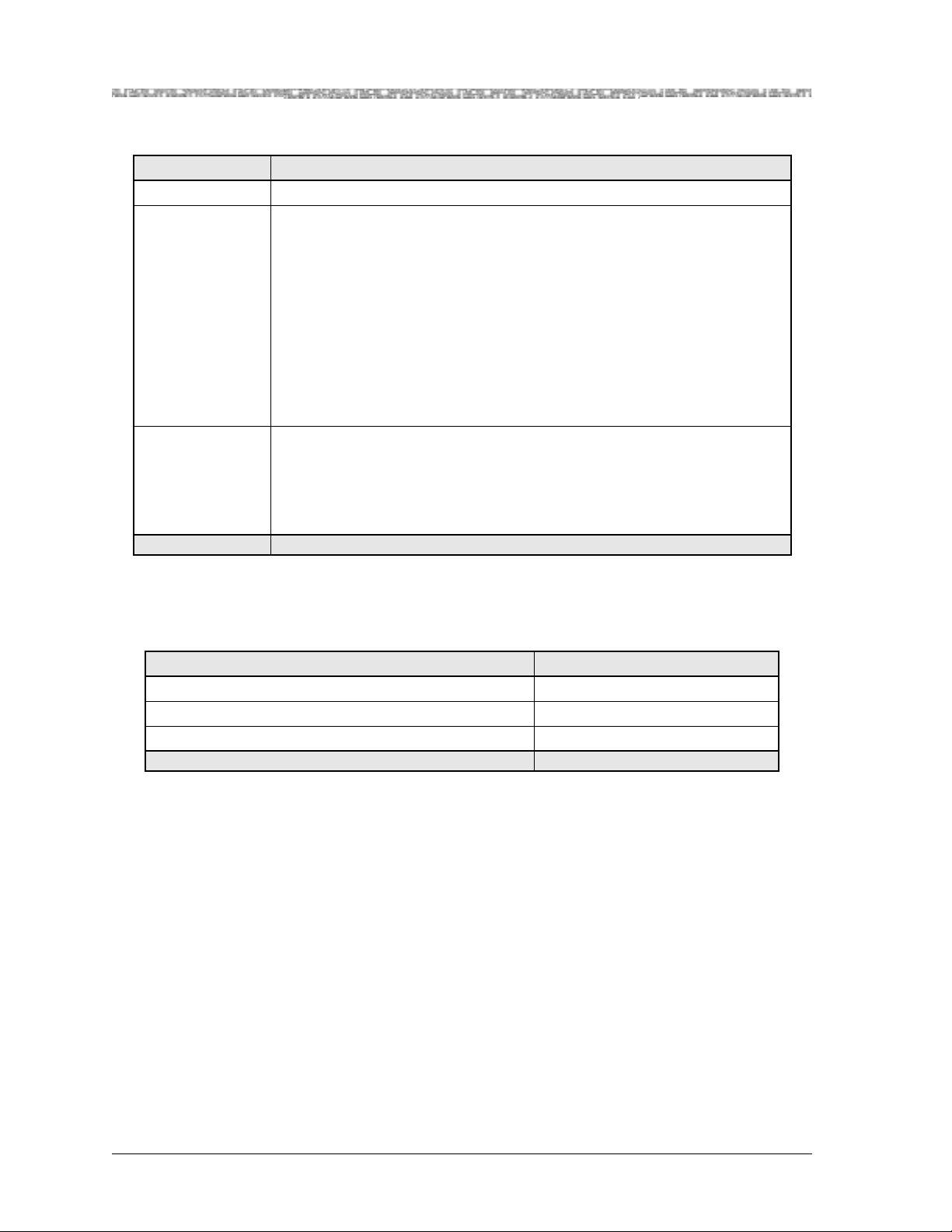
Use of Command Description Tables
All illustrations for configuration windows in this guide for the PSAX system
console interface ar e follow ed by a comma nd descr iption ta ble des cribing the
command functions displayed on the window (near the bottom of the window). You should read all the information in the command description table,
especially when first using a window, because these descriptions may have
special instructions or configuration constraints provided in the Function column by use of the
Table 1-2. Command Description Table Example
Command Function
Bring All Interfaces
Into Service
Brings the out-of-service configured interfaces to in-service status.
Note: In GR-303 configuration, it is critical to bring into service
only those channels actively configured with DS1 ports.
Note: text convention (see Table 1-2).
Use of Field Description Tables
For all illustrations for configuration windows in this guide for both the
PSAX system console interface and the AQueView EMS, the field description
tables normally follow the command description tables. Field description
tables define the editable and the display-only fields, their functions, valid
values, and constraints, if applicable. As in the command description tables,
Note: text convention is al so used , whe re appr opri ate, in t he fi eld de scrip-
the
tion tables to alert the user to sp ecial instructi ons or configu ration constr aints
(see Figure 1-1).
PacketStar® PSAX 4-Port Voice 2-Wire Office Module User Guide, Issue 1 Release 9.0.0
1-6 255-700-467
Page 23
Chapter 1 Getting Started
General Document Navigational Guidelines
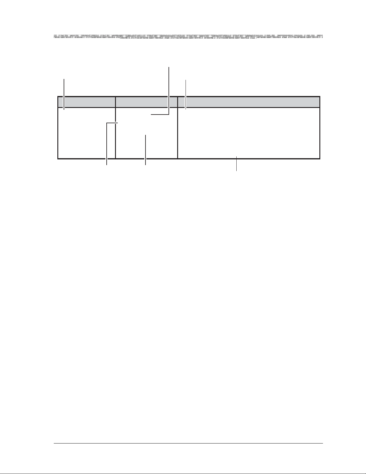
Identifies editable fields
or display-only fields on
screens
Identifies initial field
value default
Describes the function of the field
and special instructions for
configuring modules
Field Name Field Values Description
Interface Type Default: 0
Range: 0-22
Format: Numeric
Specifies the type of end-to-end connection
protocol that governs the transmission parameters
for this configured port and channel interface.
Note: When certain types of interfaces are selected in this field, other configuration fields are displayed on this window.
Identifies available
range for field value
when applicable
Figure 1-1. Field Description Table Example
Identifies field value format as
Numeric, Predefined Alphanumeric,
Hexadecimal, or Valid Dotted Quad.
Decribes special instructions or
configuration constraints
General Document Navigational Guidelines
Selecting Options, Fields, and Commands Using the Console Interface
Follow these guidelines to select an option, field, or command on the PSAX
console interface windows and to navigate through the windows:
• To select an option, field, or command, do one of the following:
~ Press the Up, Down, Left, or Right Arrow to highlight (reverse video
image) the option name, field name, or command you want to select and
press Enter as many times as necessary until the field choice you want is
displayed.
~ Use the alternate keys, K=UP, H=LEFT, L=RIGHT to highlight (reverse
video image) the option name, field name, or command you want to
select and press Enter. (You can optionally redefine these alternate keys
from the User Options window, which is accessible from the Console
Interface Main Menu window.)
~ To quickly select a command, you can also simultaneously press Ctrl and
the letter underlined in the command.
Once an option name, field, or command is selected, the system responds
as described in Table 1-3.
PacketStar® PSAX 4-Port Voice 2-Wire Office Module User Guide, Issue1 Release9.0.0
255-700-467 1-7
Page 24
Chapter 1 Getting Started
General Document Navigational Guidelines
Table 1-3. System Responses to Selecting Options, Fields, or Commands
For a selected... the following occurs:
option name The window corresponding to the option name is displayed.
field The following variations occur:
• The field entry area is blank or contains the default or previously
entered value. Press Enter to enter or change data in this field. Press
Enter again to exit edit mode.
• The field entry area, like the field name, is displayed in reverse video
image and contains a predefined set of values, which you can view or
select by pressing Enter to navigate forward thr ough these values. To
navigate backward through these field values, press Ctrl+H or the
Backspace key.
Read-only fields, which you cannot change, are enclosed in square brackets (example: [LineStatus]).
command The following variations occur:
• A message in the information line indicating an error or successful completion of the command is displayed.
• The next higher level or previous window (window name) is displayed.
• The next lower level or succeeding window (window name) is displayed.
• To navigate through the Console windows, use the shortcuts listed in
Table 1-4.
Table 1-4. Shortcut Keys for Navigating Console Interface Windows
If you want to... press...
redisplay the previous window Ctrl+B on the window.
redisplay the Console Interface Main Menu window Ctrl+G on the window.
refresh the window Ctrl+R on the window.
On all the PSAX system windows, each command or menu option has an
underlined letter. The control key plus an underlined letter is a shortcut to
that command or menu option. You can use the navigation keys and hotkeys
with the Caps Lock key on or off. Always observe the status line at the bottom of the window for instructions and information.
Selecting Menu Options and Fields in the AQueView GUI
Follow these guidelines to select a menu option or field in the AQueView GUI
windows and to navigate through the windows:
• For AQueView procedures, instructions using the term “click” mean to press
the left mouse button, and instructions using the term “right-click” mean
to press the right mouse button. (If you have a mouse with three buttons,
you will not need to use the middle mouse button to do any functions with
the AQueView EMS.)
PacketStar® PSAX 4-Port Voice 2-Wire Office Module User Guide, Issue 1 Release 9.0.0
1-8 255-700-467
Page 25

General Document Navigational Guidelines
• When multiple menu options are displayed in a procedural step, select the
menu options or click the appropriate buttons in succession as described in
Table 1-5.
Table 1-5. Selecting Multiple Menu Options or Buttons in Succession
Chapter 1 Getting Started
If you encounter a step in a procedure to
select multiple...
menu options in succession, such as the
step “Select Start > Programs > AQueView.”
then do this..
Using the left mouse button:
a Click the Start me n u option
b Click the Programs menu option
c Click the AQueView menu option
buttons in succession, such as the step,
“Click Apply > Close.”
Using the left mouse button:
a Click the Apply button.
b Click the Close button.
• Field values are displayed in three ways. To select a field, do one of the fol-
lowing methods to enter the desired values into the fields on a window in
the AQueView GUI as described in Table 1-6.
Table 1-6. How Fields Are Displayed in the AQueView GUI
For a field displayed as... do this...
a combo box (it displays with a small
triangle pointing downward)
select the displayed value and a drop-down list will appear
with additional values.
a blank box enter a valid value in the field by typing it.
grey view the information, which is read-o nly. You cannot edit
values that display as grey in the AQueView GUI.
• To quickly select menu options from the AQueView Menu Bar, you can
also simultaneously press keyboard combinations as described in Table 1-4.
Table 1-7. Shortcut Keys for Navigating the AQueView GUI
If you want to... press...
display the File menu on the AQueView Menu Bar Alt+F
display the View menu on the AQueView Menu Bar Alt+V
display the Help menu on the AQueView Menu Bar Alt+H
display the Open Device window Ctrl+O
display the Run Script window Ctrl+C
display the User List window Ctrl+U
display the Device List window Ctrl+D
PacketStar® PSAX 4-Port Voice 2-Wire Office Module User Guide, Issue1 Release9.0.0
255-700-467 1-9
Page 26

Chapter 1 Getting Started
Help Information
Table 1-7. Shortcut Keys for Navigating the AQueView GUI (Continued)
If you want to... press...
display the Users Logged On Server window Alt+L
display the User Properties window Ctrl+P
terminate the AQueView session Alt+X and Alt+F4
Help Information
The Help windows are accessible from any window in the PSAX system console interface. To access the Help windows, press the ? (Question Mark) key
on any window. In addition to the Help windows, the Console Interface windows display contextual help in the information line at the bottom of each
window. Contextual help provides information about the command or field
currently highlighted on that window. The information line also displays
error codes and responses to commands. All responses and notifications are
recorded in a trap log. See the PacketStar
Protocol (SNMP) Trap Reference Guide for details on displaying the trap log and
obtaining explanations of the trap messages.
®
PSAX Simple Network Management
To view the Help windows from the Console Interface Main Menu window,
perform the following procedure.
Begin
1 On the window for which help is desired, press the ? (question mark)
key.
The Help window for the current console window is displayed (see
Figure 1-2).
PacketStar® PSAX 4-Port Voice 2-Wire Office Module User Guide, Issue 1 Release 9.0.0
1-10 255-700-467
Page 27
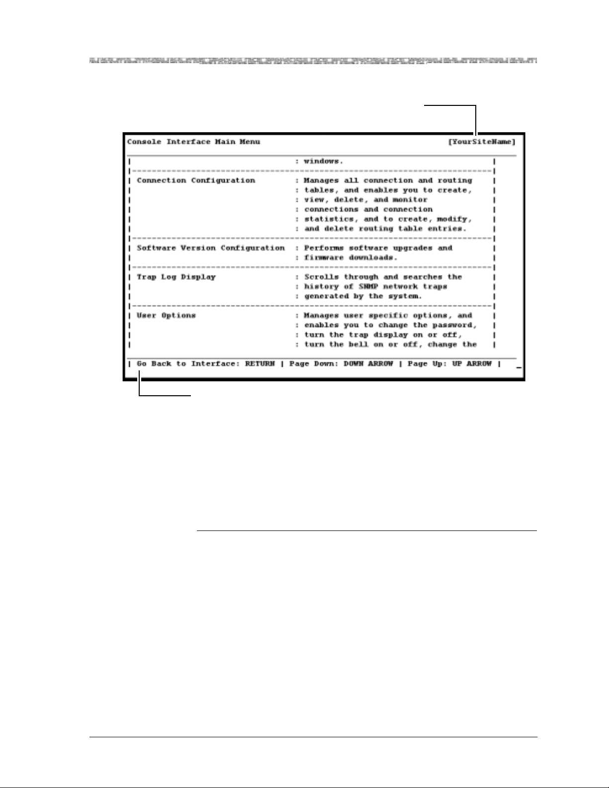
d
Your site name appears here
after initial configuration
Chapter 1 Getting Started
Technical Support
Information Line
Figure 1-2. Main Menu Help Window
2 To display the remaining Help windows for the current console window,
3 To scroll backward through the Help windows for the current console
4 To exit Help and return to the current console window, press the Enter
En
Technical Support
If you experience a problem with the 4-Port Voice 2-Wire Office module,
refer to the Lucent Technologies Product Warranty Registration Information, which
accompanied your shipment, for instructions on obtaining support in your
area.
press the Down Arrow key.
window, press the Up Arrow key.
key.
PacketStar® PSAX 4-Port Voice 2-Wire Office Module User Guide, Issue1 Release9.0.0
255-700-467 1-11
Page 28

Chapter 1 Getting Started
Before You Begin
Before You Begin
Before you start configuring and using your new 4-Port Voice 2-Wire Office
module, be sure you:
• Record your site-specific specifications such as the IP addresses you will
use, and the connections and interfaces you will need. Decide which user
names and passwords you will assign.
• Make sure you have IP connectivity to all PSAX devices to be managed
• Determine the numbering scheme for any in-band management connec-
tions you will be using
Comments on This Guide
To comment on the PacketStar® PSAX 4-Port Voice 2-Wire Office Module User
Guide, please complete the comment card at the following web address:
http://www.lucent-info.com/comments/
You can also email your comments to comments@lucent.com.
Include the following information:
Title: PacketStar
Release number: Release 9.0.0
Document number: 255-700-467
Issue number: Issue 1
Publication date: October 2003
®
PSAX 4-Port Voice 2-Wire Office Module User Guide
PacketStar® PSAX 4-Port Voice 2-Wire Office Module User Guide, Issue 1 Release 9.0.0
1-12 255-700-467
Page 29
Overview of This Chapter
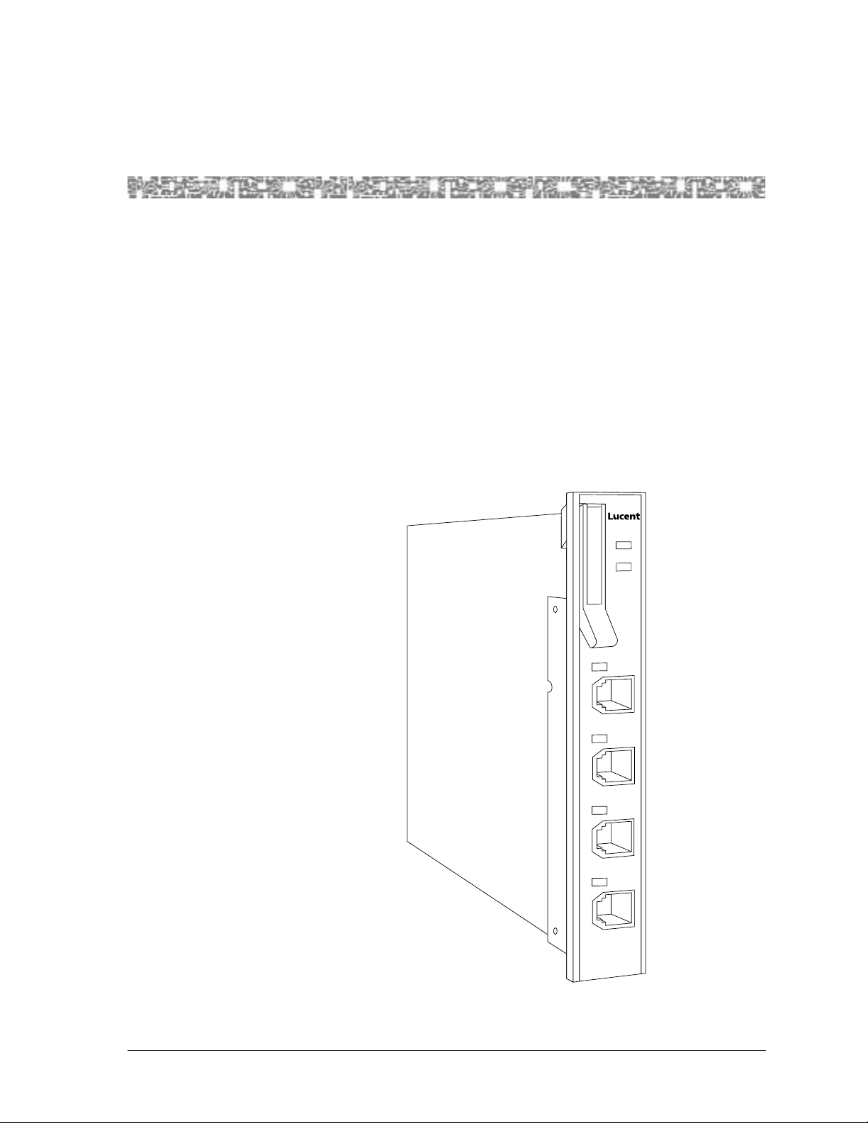
The 4-Port Voice 2-Wire Office module (20N32) provides support for the
office (central office or PABX switch) end of a two-wire analog telephone
line. This allows a voice loop from a voice switch to be connected directly to a
Multiservice Media Gateway system over an ATM network to a distant telephone or other analog device. The coding translation supported by this module is µ-law to µ-law only.
The module has three types of light-emitting diode (LED) indicators:
ACTIVE, FAIL, and LOS (loss of signal). On the faceplate, each port has a LOS
LED which turns on when the port goes off-hook. It also flashes in synchronization with an incoming ringing signal to the port.
2 Module Description
FAIL
1
ACTIVE
VOICE
2WO
1
2
3
4
Figure 2-1. 4-Port Voice 2-Wire Office Module
PacketStar® PSAX 4-Port Voice 2-Wire Office Module User Guide, Issue1 Release9.0.0
255-700-467 2-1
Page 30

Chapter 2 Module Description
4-Port Voice 2-Wire Office Module
4-Port Voice 2-Wire Office Module
This module is typically configured with an 8-Port Voice 2-Wire Station module via a PVC connecti on to e nable a f orei gn exchange (FXO) v oice service to
be transmitted across an ATM network. With FXO service, the voice switch
provides dial tone, ringing, and digit translation, which are not provided by
the A TM network.
Module Placement Requirements
You may install the 4-Port Voice 2-Wire Office module in any I/O slot in any
PSAX Multiservice Media Gateway chassis intended to contain I/O or server
modules. In typical applications, this module is used with the 8-Port 2-Wire
Station module.
Hardware Features
The 4-Port Voice 2-Wire Office module supports these hardware features:
• Number of ports: 4
• Connector type: RJ-11
• Ringing frequency: 20 Hz
• Termination impedance: 600 Ohms
• Signaling: dual tone multi-frequency (DTMF)
• Supervision: loop start
General Hardware Specifications
Table 2-1 provides the general physical hardware and environmental specifications for the PacketStar PSAX I/O and server modules.
Table 2-1. Physical Hardware Specifications for PSAX I/O and Server Modules
Specification Description
Dimensions 17.3 cm H x 2.41 cm W x 24.1 cm D
(6.8 in. H x 0.95 in. W x 9.5 in. D)
Weight 0.45 kg (1.0 lb.), approximate
Weight 0.45 kg (1.0 lb.)
Operating temperature range for all the
PSAX 1250, PSAX 2300, and
PSAX 4500 systems
Operating temperature range for the
PSAX 1000 systems
0° to 50° C (32° to 122° F)
For AC-powered PSAX 1000 systems:
0° to 50° C (32° to 122° F)
For DC-powered PSAX 1000 systems:
-20° to 60° C (-4° to 140° F) with a cold start minimum of
0° C (32° F)
PacketStar® PSAX 4-Port Voice 2-Wire Office Module User Guide, Issue 1 Release 9.0.0
2-2 255-700-467
Page 31

Chapter 2 Module Description
Chassis Speed, Power Consumption, and Memory Allocation
Table 2-1. Physical Hardware Specifications for PSAX I/O and Server Modules (Continued)
Specification Description
Operating humidity range for all chassis 5% to 85% relative humidity
Operating altitude range for all chassis 60 meters (197 feet) below sea level to 4,000 meters
(13,123 feet) above sea level
Storage temperature range for all
-40° to 70° C (-40° to 158° F)
chassis
Storage humidity range for all chassis 0% to 90% noncondensing
Additional information can be found in the appropriate PacketStar PS AX
module user guides.
Chassis Speed, Power Consumption, and Memory Allocation
Table 2-2 provides the chassis speed, power consumption, and memory allocation specifications for this module.
Table 2-2. Performance and Power Specifications for the 4-Port Voice 2-Wire Office Module
Module
20N32 4-Port Voice
2-Wire Office
Total
Amount of
SDRAM
8MB 4MB N/A N/A Low
Module
Program and
Data Space
Maximum
Input
Buffer
Output
Buffer
Chassis
Speed
Speed
Maximum
Power
Consumption
14 W
LED Indicators
T able 2-3 describes how the LED indicators on the 4-Port V oice 2-Wire Office
module respond to different module conditions. These LEDs indicate if the
module has been installed properly. Before you configure the module, you
must ensure that it is properly initialized according to the information provided in Table 2-3.
PacketStar® PSAX 4-Port Voice 2-Wire Office Module User Guide, Issue1 Release9.0.0
255-700-467 2-3
Page 32

Chapter 2 Module Description
LED Indicators
Table 2-3. LED Indicators for the 4-Port Voice 2-Wire Office Module
Module Status
LED
FAIL
(red)
Initial
Power-On
Lights
*
briefly
No
Configured
Ports
One or More
Configured Ports
Not lit Lights only when
the module is not
functioning
ACTIVE
(green)
Lights
briefly
Not lit Lights only when
*
the module is functioning properly
1–4
(green)
*
Each lights
briefly
After power is initially applied to the system and the system boot is complete, the FAIL and ACTIVE
LEDs indicate whether the module has no configured ports (red), or one or more configured ports
(green).
Not Applicable
Not Applicable Not lighted Flashing LED indicates
No Cable on
Port
Not Applicable
Not Applicable
Cable on Port
Not Applicable
Not Applicable
the line is ringing. Solid
LED indicates the line is
off-hook (in use) or
busy. Unilluminated
LED indicates the line is
on-hook (not in use).
Note: Shielded RJ-12 to RJ-12, straight through cables are needed with
the 4-Port Voice 2-Wire Office module.
PacketStar® PSAX 4-Port Voice 2-Wire Office Module User Guide, Issue 1 Release 9.0.0
2-4 255-700-467
Page 33

3 Configuring Ports and Channels
Using the Console Interface
Overview of This Chapter
This chapter describes how to use the console interface to perform the following tasks on the 4-Port Voice 2-Wire Office module:
• Obtaining general module data and accessing ports and channels
• Setting the values for the port and channel configuration of the 4-Port
Voice 2-Wire Office module
Before You Begin
Be sure to complete the following tasks first before configuring the 4-Port
Voice 2-Wire Office module:
• Configure your basic system (see “Configuring the System for Your Site” in
the appropriate PacketStar PSAX Multiservice Media Gateway user guide).
• Configure the Stratum 3–4 module (see “Configuring the Stratum 3–4
Module” in the appropriate PacketStar PSAX Multiservice Media Gateway
user guide).
When configuring the 4-Port Voice 2-Wire Office module using the console
interface, display-only fields are displayed in square brackets ([ ]).
!
CAUTION:
Due to the copper wire interface between an Enhanced DS1 or E1 module and a PBX and/or key telephone system, the PSAX system and the
other equipment should use a common chassis ground connection to
avoid ground current loops, which could affect voice quality.
Using the Equipment Configuration Window
This section describes how to obtain product, model, version, and serial number data about a module from the Equipment Configuration window. In
addition, the window provides operational status and alarm conditions on
each installed module. You also use this window to access the port and channel configuration windows for the PSAX modules.
Accessing the Equipment Configuration Window
Perform the following procedure to acces s the Equipme nt Configurat ion window.
PacketStar® PSAX 4-Port Voice 2-Wire Office Module User Guide, Issue1 Release9.0.0
255-700-467 3-1
Page 34

Chapter 3 Configuring Ports and Channels Using the Console Interface
Using the Equipment Configuration Window
Begin
1 On the Console Interface Main Menu window, select the Equipment
Configuration option.
The Equipment Configuration window is displayed (see Figure 3-1
through Figure 3-5).
2 View the operational and alarm status, software version, PEC, and serial
number data of the installed modules.
3 When you are ready to begin configuring the ports and channels of the
module, select the line displaying the name of the module you want to
configure.
4 Proceed to the section, “Configuring the Ports,” for module configuration
procedures.
Note: The sample Equipment Configuration windows in the following
figures may not show the actual module you are configuring.
These figures illustrate the variations of slot configurations for
the different PSAX chassis displayed on the Equipment Configuration window.
End
Figure 3-1. Sample Equipment Configuration Window on a PSAX 1000 System
(Page 1)
PacketStar® PSAX 4-Port Voice 2-Wire Office Module User Guide, Issue 1 Release 9.0.0
3-2 255-700-467
Page 35

Chapter 3 Configuring Ports and Channels Using the Console Interface
Using the Equipment Configuration Window
Figure 3-2. Sample Equipment Configuration Window on a PSAX 1250 System
(Page 1)
Figure 3-3. Sample Equipment Configuration Window on a PSAX 2300 or
PSAX 4500 System (Page 1)
PacketStar® PSAX 4-Port Voice 2-Wire Office Module User Guide, Issue1 Release9.0.0
255-700-467 3-3
Page 36

Chapter 3 Configuring Ports and Channels Using the Console Interface
Using the Equipment Configuration Window
Figure 3-4. Sample Equipment Configuration Window on a PSAX 1000,
PSAX 2300, or PSAX 4500 System (Page 2)
Figure 3-5. Sample Equipment Configuration Window on a PSAX 1250 System
(Page 2)
Commands The commands in this window have the following functions.
PacketStar® PSAX 4-Port Voice 2-Wire Office Module User Guide, Issue 1 Release 9.0.0
3-4 255-700-467
Page 37

Chapter 3 Configuring Ports and Channels Using the Console Interface
Using the Equipment Configuration Window
Table 3-1. Commands for the Equipment Configuration Window
Command Function
Update Equipment Display Refreshes the current status of the modules in the PSAX
chassis.
Page Down Displays the second page of the Equipment Configuration
window.
Page Up Displays the first page of the Equipment Configuration
window.
Interface by Name Displays the Interface Name Table window on which you
can view all the interface names in the PSAX system.
Go Back to Main Menu Redisplays the Console Interface Main Menu window.
Field Description The display-only fields on this window are described in Table 3-2.
Table 3-2. Field Descriptions for the Equipment Configuration Window
Field Name Field Valu es Description
Slot Default: N/A
Displays the slot number in the PSAX chassis.
Range: 1–25, depending on chassis type
Format: Numeric
Module Type Default: N/A
Range: from PSAX
system database
Format: Predefin ed
alphanumeric
Displays the type of the module in the slot. When
a module is inserted into the chassis, its name is
displayed in the Module Type field next to the
slot number. When the module is removed from
the chassis, its name is no longer displayed in the
Module Type field and is replaced with None.
Status Default: Unknown
Displays the operational status of the module.
Range: N/A
Format: Predefin ed
alphanumeric
Unknown Indicates that the module has not been config-
ured.
Primary Indicates one of the following:
• at least one port or channel on an I/O module
has been configured.
• a CPU module is functioning as the primary
CPU module.
Standby Indicates one of the following:
• a module in red undant systems is operating as
the standby (backup) module to the primary
(active) module.
• a CPU module in redundant systems is functioning as the standby (backup) CPU module.
PacketStar® PSAX 4-Port Voice 2-Wire Office Module User Guide, Issue1 Release9.0.0
255-700-467 3-5
Page 38

Chapter 3 Configuring Ports and Channels Using the Console Interface
Using the Equipment Configuration Window
Table 3-2. Field Descriptions for the Equipment Configuration Window (Continued)
Field Name Field Valu es Description
Alarm Status Default: No Alarm
Range: N/A
Format: Predefin ed
alphanumeric
SW # Default: N/A
Range: (from module
firmware)
Format: Predefin ed
alphanumeric
Displays the present alarm condition of the module. For the alarm status conditions, see the table
“Alarm Status Descriptions for Modules” following this field description table.
Displays the version of PSAX system software
with which the modules’ firmware was released.
The software version is encoded in the module
firmware. Because not all modules require firmware upgrades with every new PSAX sys te m sof tware release, the software version that is displayed in this window may be lower than the
CPU system software that is currently running on
the PSAX system. See the most recent Release
Note document for the latest software and firmware lineup information.
PEC Default: N/A
Range: from module
bootloader
Displays the product element code (PEC) used to
identify and order this type of module. The PEC is
encoded in the module bootloader.
Format: Predefin ed
alphanumeric
Serial # Default: N/A
Range: (from module
firmware)
Format: Predefin ed
alphanumeric
Displays the unique serial number of the individual module. The product serial number is
encoded in the module firmware. The format of
this field is the following:
PSAX System Rel. 6.5.0 and later: 12- dig it number in the format: YYVVDDnnnnnn, where YY =
year of manufacture VV = vendor ID code (manufacturer and location) DD = date code of manu-
facture (either month or week depending on
vendor’s preference) nnnnnn = sequential number, wh ich in conjunction with YY, VV, and DD,
creates a unique number for each hardware component in the PSAX product line
For existing products with the 10-digit serial
number used in Rel. 6.5.0 or later systems, this
number is displayed with two preceding zeros.
PSAX Rel. 6.3.0 and earlier: 10-digit number. For
products with 12-digit serial numbers used in
Rel 6.3.0 or earlier systems, the first two digits
(YY) are not displayed.
Alarm Status Values
The alarm status descriptions for the Alarm Status field on the Equipment
Configuration window are provided in Table 3-3.
PacketStar® PSAX 4-Port Voice 2-Wire Office Module User Guide, Issue 1 Release 9.0.0
3-6 255-700-467
Page 39

Chapter 3 Configuring Ports and Channels Using the Console Interface
Configuring the Ports
Table 3-3. Alarm Status Descriptions for Modules on the Equipment Configuration Window
Alarm Status
Module Type
Affected
Description
NoAlarm I/O and Server Indicates that no alarms have been detected for the mod-
ule in this slot.
WrongCardType I/O and Server Indicates that one type of module was configured in this
slot in the chassis, but a now different module occupies
this slot.
LineFailed All Indicates that the module in this slot is no longer receiv-
ing or transmitting signals because the line failed.
Hexadecimal format,
Example:
12345678ABC
I/O and Server Indicates that one or more ports on the module in this
slot currently have a loss of signal. The numbers indicate
which ports have a loss of signal. For modules that have
more than eight ports not receiving signals, the value in
this field is in hexadecimal format.
CardRemoved All Indicates that one of the following events occurred:
• The module in this slot was configured and then
removed from the slot.
• Connections on the OC-3, OC-12, STM-1, or STM-4
APS/MSP prim ar y mo du le i n thi s s l ot wer e tr ans f erred
to the standby module. After the transfer occurs, the
former primary module then displays CardRemoved
in the Alarm Status field; the former standby module
then displays Primary in the Status field.
ReferenceClockFailed Stratum 3–4 Indicates that the timing reference clock on the Stratum
module in this slot failed.
CompositeClockFailed Stratum 3–4 Indicates that the timing composite clock on the Stratum
module in this slot failed.
Overload Power Supply Indicates that the Power Supply module is operating
under an overload condition.
PowerFailed Power Supply Indicates that the power has failed.
Minus48vFailed Power Supply Indicates that the -48 V dc Power Supply module output
failed.
UnknownAlarm I/O and Server Indicates that the reason for failure is not known.
CompleteClockFailed Stratum 3–4 Indicates that the backplane detect ed a clock error.
PowerFailed Power Supply Indicates that no power is coming into the PSAX chassis.
Configuring the Ports
To configure the 4-Port Voice 2-Wire Office module ports, follow the following procedure.
PacketStar® PSAX 4-Port Voice 2-Wire Office Module User Guide, Issue1 Release9.0.0
255-700-467 3-7
Page 40

Chapter 3 Configuring Ports and Channels Using the Console Interface
Configuring the Ports
Configuring the Ports
Begin
1 On the Console Interface Main Menu window (see Figure 3-6), select the
Equipment Configuration option and press Enter.
Figure 3-6. Console Interface Main Menu (Equipment Configuration Selected)
The Equipment Configuration window (see Figure 3-7) is displayed.
PacketStar® PSAX 4-Port Voice 2-Wire Office Module User Guide, Issue 1 Release 9.0.0
3-8 255-700-467
Page 41

Chapter 3 Configuring Ports and Channels Using the Console Interface
Configuring the Ports
Figure 3-7. Equipment Configuration Window (As Displayed on the PSAX 1000,
PSAX 1250, PSAX 2300, and PSAX 4500 Console)
2 On the Equipment Configuration window , sele ct the 4-Port Voice 2-Wire
Office module and press Enter.
The Two Wire Office Configuration window is displayed (see Figure 3-8).
Figure 3-8. Two Wire Office Configuration Window
Commands Table 3-4 describes the commands on this window:
PacketStar® PSAX 4-Port Voice 2-Wire Office Module User Guide, Issue1 Release9.0.0
255-700-467 3-9
Page 42

Chapter 3 Configuring Ports and Channels Using the Console Interface
Configuring the Ports
Table 3-4. Commands for the Two Wire Station Configuration Window
Command Function
Update Display Updates the values in the fields to show the most cur-
rent configuration. Use this command mostly to display the most current information in the Line Status
field.
Configure All Interfaces Sets all four ports to the circuit emulation type inter-
face. The value CircuitEmulation is displayed in the
Interface Type field, and the value OutOfService is
displayed in the Oper Status field.
Delete All Interfaces Deletes the configured interfaces for all four ports. The
value Unconfigured is displayed in the Interface Type
and the Oper Status fields.
Note: You must first take all interfaces out of service
(using the Take All Interfaces Out Of Service com-
mand) before you can use this command to delete all
the configured interfaces.
Bring All Interfaces Into
Service
Take All Interfaces Out Of
Service
Go Back to Equipment Configuration
3 To configure the ports, do one of the following:
a. If you want to configure all four ports with the default port field val-
ues given in Table 3-6, select the Configure All Interfaces command and press Enter.
The value CircuitEmulation is displayed in the Interface Typefield, and
the value OutOfService is displayed in the Oper Status field.
b. To configure one port at a time (to set values other than the default
ones), select the line for the port you want to configure and press
Enter.
Brings the out-of-service configured interfaces for all
four ports to in-service status. The value InService is
displayed in the Oper Status field for all four ports.
Takes the in-service configured interfaces for all four
ports to out-of-service st atus. The value OutOfSer-
vice is displayed in the Oper Status field for all four
ports.
Note: You must use this command first before using
the Delete All Interfaces command.
Redisplays the Equipment Configuration window.
The Two Wire Office Port and Channel Configuration window (see
Figure 3-9) is displayed.
PacketStar® PSAX 4-Port Voice 2-Wire Office Module User Guide, Issue 1 Release 9.0.0
3-10 255-700-467
Page 43

Chapter 3 Configuring Ports and Channels Using the Console Interface
Configuring the Ports
Figure 3-9. Two Wire Office Port and Channel Configuration Window
Commands Table 3-5 describes the commands on this window:
Table 3-5. Commands for the Voice Two Wire Office Port and Channel Configuration Window
Command Function
Apply Port and Channel Config-
Applies the configuration field values you set.
uration
Reset Port and Channel Display Resets the fields to the last set of saved values.
Bring Interface Into Service Brings an out-of-service configured interface to in-ser-
vice status. This command is displayed when the [Oper
Status] field is OutOfService. The value InService is
displayed in the [Oper Status] field. When this command is executed, the Take Interface Out of Service
command is displayed instead.
Take Interface Out of Service Takes an in-service configured interface to out-of-ser-
vice status. Command is displayed when the [Oper
Status] field is InService. The value OutOfService is
displayed in the [Oper Status] field.
Configure Interface Displays the Circuit Emulation Inter face Co nfigura tion
window.
Enter to Card Configuration Redisplays the Two Wire Office Configuration window.
4 Select the values for the fields on this window from the values given in
Table 3-6.
PacketStar® PSAX 4-Port Voice 2-Wire Office Module User Guide, Issue1 Release9.0.0
255-700-467 3-11
Page 44

Chapter 3 Configuring Ports and Channels Using the Console Interface
Configuring the Ports
Table 3-6. Field Descriptions for the Two Wire Office Port and Channel Configuration Window
Field Name Field Valu es Description
Test Mode Defau lt: Default: Off
Specifies the test mode of the module.
Range: N/A
Format: Predefin ed
Off The module is not in test mode.
QuietTime Quiet Time is useful only if the line is not quiet
enough. If the line is no isy, the quiet time fea ture
will help you to determine whether the channel
is noisy. If noise is present on the line, then the
channel is defective.
Note: Do not select this value unless the line is
noisy.
F-1004Hz A 1004 Hz tone is used in troubleshooting a sys-
tem where a line is seized by bridging the tip and
ring wires through a resistance.
[Signaling Bits] Ab Signaling bits method supported is AB (two-bit
signaling).
[Dial Mode] Dtmf Dual tone multi-frequency
[Loop Detect] LoopStart Loop detection.
[Line Status] Default: NoAlarm
Range: N/A
Format: Predefin ed
Indicates the Line Status of the interface. It con-
tains loopback, failure, received alarm and trans-
mitted alarm information. For a line status mes-
sage list, see the Reference Appendix in this
guide.
Interface Type Default: Unconfig-
Specifies whether the interface is assigned or not.
ured
Range: N/A
Format: Predefin ed
Unconfigured This interface is not configured.
Circuit Emulatio n This interface is configured for circuit emulation.
[Oper Status] Defau l t: Unconfig-
ured
Specifies whether the channel can pass traffi ce or
not.
Range: N/A
Format: Predefin ed
Unconfigured This channel is not operational because the inter-
face is not configured
InService This channel is capable of receiving and sending
signals.
OutOfService This channel is not capable of receiving and send-
ing signals.
PacketStar® PSAX 4-Port Voice 2-Wire Office Module User Guide, Issue 1 Release 9.0.0
3-12 255-700-467
Page 45

Chapter 3 Configuring Ports and Channels Using the Console Interface
Saving the Equipment Configuration and Logging Off
Table 3-6. Field Descriptions for the Two Wire Office Port and Channel Configuration Window
Field Name Field Valu es Description
[Silence Suppression]
Default: Pvc
Range: N/A
Permanent virtual circuit (PVC).
Format: Predefin ed
[Echo Cancellation] Default: Disabled
Silence suppression is disabled.
Range: N/A
Format: Predefin ed
[Voice Compression]
Disabled The echo cancellation function is disabled. This
function is a method for isolating and filtering
unwanted signal energy caused by echoes from
the main transmitted signal.
[Companding Law] Disabled Voice compression is disabled.
[AAL Encapsulation]
[Silence Suppres-
MuLawPCM The PCM coding and companding standard used
in North America and Japan.
Aal1 ATM Adaptation Layer 1 (AAL1)
sion]
[Service Type] Fxo Foreign exchange office (FXO)
5 To apply the values for the fields on this window, select the Apply Port
and Channel Configuration command and press Enter.
6 Select the Configure Interface command and press Enter.
The Circuit Emulation Interface Configuration window is displayed.
Note: For information on configuring the Circuit Emulation interface
using the AC console, see chapter 5.
7 Repeat this procedure for the remainder of the ports, as needed.
Note: Whenever needed, use the commands in the Two Wire Office Con-
figuration window (see Figure 3-8 on page 3-9) and on the Two
Wire Office Port and Channel Configuration window (see
Figure 3-9 on page 3-11) to manage the interfaces.
End
Saving the Equipment Configuration and Logging Off
After configuring the module ports and channels, the interface types for each
port and channel, and the connections, you must save the values to the
PSAX system database. It is recommended that you save your values frequently as you progress through your work, at a minimum, after finishing
each stage of work:
• Configuring each module in your system
• Configuring the connections in your system
PacketStar® PSAX 4-Port Voice 2-Wire Office Module User Guide, Issue1 Release9.0.0
255-700-467 3-13
Page 46

Chapter 3 Configuring Ports and Channels Using the Console Interface
Saving the Equipment Configuration and Logging Off
• Before exiting your current console session
Perform the following procedure to permanently save the values for your
system.
!
CAUTION:
If your system loses power or if you reboot the chassis, and you have not
yet saved the values permanently, you will lose all unsaved values you
have applied on the various windows.
Begin
1 To return to the Console Interface Main Menu window, press Ctrl+G.
On the Console Interface Main Menu window, [Modified] is displayed
next to the Save Configuration command, indicating you have made
changes to the system that are not yet sav ed to the PSAX system databa se
(see Figure 3-10).
Figure 3-10. Save Configuration [Modified] (Before Saving)
2 Select the Save Configuration command or press Ctrl+A.
Wait a few seconds while the system writes the values to the PSAX system database. The system displays the following message while it is executing this command:
Saving the equipment and connection information
PacketStar® PSAX 4-Port Voice 2-Wire Office Module User Guide, Issue 1 Release 9.0.0
3-14 255-700-467
Page 47

Chapter 3 Configuring Ports and Channels Using the Console Interface
d
Saving the Equipment Configuration and Logging Off
Note: In PSAX systems with redundant CPUn modules, the stan db y
CPUn module reboots every time you save the configuration on
the primary CPUn module. This event is a function of the SVC
retention feature and the result of saving the configuration
changes you have made.
When the save configuration function is completed, the system displays
an appropriate message as described in Table 3-7.
Table 3-7. Messages Generated after the Save Configuration Process
When a PSAX
system is...
the system displays...
nonredundant T-SaveConfiguration: saveConfigurationReasonCode=All-OK
redundant
T-SaveConfiguration: saveConfigurationReasonCode =
Expect2ndCPUCardFailedOrRemoved
*
The standby CPUn module is rebooted when the save command is issued.
After the standby CPUn module reboots, the system displays the following
message:
Code=FileTransferCompleted
*
This message indicates that while the standby CPUn module reboots after you select the Save
Configuration
T-SaveConfiguration: saveConfigurationReason-
command, the st and by CP U n module is temporarily unavailable.
After saving the configuration values, the indicator [Modified] is no
longer displayed next to the Save Configuration command.
En
PacketStar® PSAX 4-Port Voice 2-Wire Office Module User Guide, Issue1 Release9.0.0
255-700-467 3-15
Page 48

Chapter 3 Configuring Ports and Channels Using the Console Interface
Saving the Equipment Configuration and Logging Off
PacketStar® PSAX 4-Port Voice 2-Wire Office Module User Guide, Issue 1 Release 9.0.0
3-16 255-700-467
Page 49

4 Configuring Interfaces Using the
Console Interface
Before You Begin
Before you can set interface configur at ion values , you mu st have s elect ed an
interface type value other than Unconfigured in the Interface Type field on
the module’s Port and Channel Configuration window.
This chapter provides instructions for configuring the circuit emulation interface type for the module using the Multiservice Media Gateway console.
For a matrix of the available interface types by PSAX I/O module types, see
the Interface Types by I/O Module Types table in the appendix, “Reference
Information.”
Errors When Applying Interfaces to Ports
An error may occur when you apply an interface to channel. If an error condition occurs, the PSAX system sends an SNMP trap that is usually displayed
in the console Trap Log Display window (accessible from the Console Interface Main Menu window). The list below includes the most common interface errors that cause the PSAX system to display a message. (See the Packet-
®
PSAX Simple Network Management Protocol (SNMP) Trap Reference Guide for
Star
more information about the SNMP traps related to interface errors).
• Entering field values that are outside of the configurable range of values
• Attempting to configure an interface for a port or channel that has already
been configured
• Attempting to configure an interface that is already in service (must be out
of service to be configured or change field values)
• Entering field values that are not recognized by the PSAX system software
The Circuit Emulation Interface
Managing Circuit Emulation Interfaces
This section provides instructions for managing interfaces by performing the
following tasks:
• Configuring and applying interface(s)
• Bringing interface(s) into service
• Taking interface(s) out of service
• Viewing interface(s)
• Deleting interface(s)
PacketStar® PSAX 4-Port Voice 2-Wire Office Module User Guide, Issue1 Release9.0.0
255-700-467 4-1
Page 50

Chapter 4 Configuring Interfaces Using the Console Interface
d
The Circuit Emulation Interface
• Viewing interface statistics
Configuring a Circuit Emulation Interface
This section provides instructions for configuring an I/O module for the circuit emulation interface.
Note: To display the windows for configuring a circuit emulation inter-
face (see Figure 4-1), you must have completed the following
three steps in a previous procedure:
1. Selected the value CircuitEmulation in the Interface Type field on the
appropriate Port and Channel, DS1 Channel, or Virtual DS1 Channel
Configuration window of the module that you are configuring for circuit
emulation.
Note: Channel strapping is done before the Apply Configuration
step below. (For instructions, see the Port and Channel Configuration chapter of this guide).
2. Selected the Apply Configuration command.
3. Selected the Configure Interface command. The Circuit Emulation
Interface Configuration window (see Figure 4-1) is displayed. Table 4-1
describes the commands for the window. Table 4-2 describes the fields on
the window.
Begin
1 On the Circuit Emulation Interface Configuration window, enter the val-
ues in the fields on this window according to the information provided in
Table 4-2.
2 Select the Apply Interfac e Conf ig ur at i on co mm a n d to se t th e values
you selected.
3 If your configuration requires you to bring the interface into service at
this time, do so by selecting the Bring Interface Into Service command. For more information on other configuration windows on which
you can bring interfaces into service, see the “Bringing One or More Circuit Emulation Interfaces into Service” procedure in this guide.
En
PacketStar® PSAX 4-Port Voice 2-Wire Office Module User Guide, Issue 1 Release 9.0.0
4-2 255-700-467
Page 51

Chapter 4 Configuring Interfaces Using the Console Interface
The Circuit Emulation Interface
Figure 4-1. Circuit Emulation Interface Configuration Window
Commands The commands on this window have the following functions:
Table 4-1. Commands for the Circuit Emulation Interface Window
Command Function
Bring Interface Into Service Brings an out-of-service configured interface to in-
service status. The value InService is displayed in
the [Admin Status] field.
Note: This command is displayed when the [Admin
Status] field i s OutOfService. You must first configure the interface before you can use this command.
Tak e In terf ac e Out of Servic e Takes an in-service configured interface to out-of-
service sta tus . The va lue OutOfService is displayed
in the [Admin Status] field.
Note: This command is displayed when the [Admin
Status] field is InService. You must use this command first before using the Dele te In terf ac e and
Return command.
Add Interface Applies the configuration field values you set.
PacketStar® PSAX 4-Port Voice 2-Wire Office Module User Guide, Issue1 Release9.0.0
255-700-467 4-3
Page 52

Chapter 4 Configuring Interfaces Using the Console Interface
d
The Circuit Emulation Interface
Table 4-1. Commands for the Circuit Emulation Interface Window (Continued)
Command Function
Delete Interface and Return Deletes an out-of-service interface and redisplays
the Port and Channel Configuration window for the
module you are configuring.
Note: You must first take interface out of service
(using the Take Interface Out of Service com-
mand) before you can use this command.
Go Back to Port Configuration Redisplays the Port and Channel Configuration win-
dow of the module you are configuring.
Bringing a Circuit Emulation Interface Into Service
Begin
Note: You may bring the Circuit Emulation interface into service from
either of these windows:
• the module port and channel configuration window
• the Circuit Emulation Interface Configuratio n Window.
Make sure that the module configuration is complete before bringing the
interface into service.
To bring the interface into service on the Circuit Emulation Interface Configuration Window, select the Bring Interface Into Service command, (or
press Ctrl+N). The InService value is displayed in the [Admin Status] field.
En
Viewing the Parameters of a Specific Circuit Emulation Interface
Begin
The circuit emulation interface window is accessed for viewing by the
same navigational steps as the “Configuring an Interface...” procedure.
This path may vary depending on the module you used (see the Reference Information appendix in this guide for a list of what modules can be
used for the interfaces available). You should always view an interface
and determine whether you have chos en the correct one bef ore you perform any of the procedures in step 2 below.
1 Return to the Console Interface Main Menu for the module you config-
ured the Circuit Emulation interface on an d rep eat the st eps in t he “C onfiguring a Circuit Emulation Interface” procedure in this guide until you
access the Circuit Emulation Interface Configuration window.
2 Proceed to one of the following sections, as needed:
• Bringing One or More Circuit Emulation Interfaces into Service
PacketStar® PSAX 4-Port Voice 2-Wire Office Module User Guide, Issue 1 Release 9.0.0
4-4 255-700-467
Page 53

Chapter 4 Configuring Interfaces Using the Console Interface
d
d
• Taking One or More Circuit Emulation Interfaces out of Service
• Deleting One or More Circuit Emulation Interfaces
End
Viewing the Circuit Emulation Module Port Statistics
T o view the Circuit Emulation in terface s tatistics , perfo rm the steps i n the following procedure.
Begin
The Circuit Emulation Interface Statistics are viewed on the Port Statistics
window of the module you are using for the Circuit Emulation Interface.
Access this window from the module port and channel configuration window . See the appropriate module guide for more details on module port statistics windows.
Traffic must have passed on the connection before statistics will display.
En
The Circuit Emulation Interface
Taking a Circuit Emulation Interface Out of Service
Note: You may take a Circuit Emulation interface out of service from
either of these windows:
• the module port and channel configuration window
• the Circuit Emulation Interface Configuration window.
Make sure that the module configuration is complete.
Begin
1 To take the interface out of service on the Circuit Emulation Interface
Configuration Window, select the Take Interface Out Of Service com-
mand (or press Ctrl+N).
On the Circuit Emulation Interface Configuration Window, the window
status line prompts:
Taking the interface down will lose all configurations. Continue? (y/n)
On the module Port and Channel Configuration window, the status line
prompts:
Are you SURE that you want to take ALL interfaces out of service? (y/n)
2 Select Y.
The OutOfService value is displayed in the [Admin Status] field.
En
PacketStar® PSAX 4-Port Voice 2-Wire Office Module User Guide, Issue1 Release9.0.0
255-700-467 4-5
Page 54

Chapter 4 Configuring Interfaces Using the Console Interface
The Circuit Emulation Interface
Deleting a Circuit Emulation Interface
Begin
Note: You may delete the Circuit Emulation interface from either of
these windows:
• the module port and channel configuration window, or
• the Circuit Emulation Interface Configuration Window. In either
case, you must first take the interface out of service.
T o delete the interface o n the Circuit Emulat ion Interface Co nfiguration Window, proceed as follows:
1 Select the Take Interface Out Of Service command.
On the module Port and Channel Configuration window, the window
prompt reads:
Are you SURE that you want to take ALL interfaces out of service? (y/n)
On the Circuit Emulation Interface Configuration window, the window
prompt reads:
Taking the interface down will cause all SVCs to be lost.
Continue? (y/n)
2 Type Y to continue.
The OutOfService value is displayed in the [Admin Status] field.
3 Select the Delete Interface and Return command and press Enter.
On the module Port and Channel Configuration window, the window
prompt reads:
Are you SURE that you want to take ALL interfaces out of service? (y/n)
On the Circuit Emulation Interface Configuration window, the window
prompt reads:
Are you SURE that you want to delete this interface? (y/n)
4 Press Y The interface is deleted and you are returned to the port and
channel configuration window.
End
Modifying a Circuit Emulation Interface
After you have configured an Circuit Emulation interface for a specified port
and channel, you cannot directly change the parameters for this interface
even if it is out of service. The concept for “modifying” (replacing) an Circuit
Emulation interface is that you delete the interface with the parameters you
no longer want for a specified port and channel, and then configure a new
interface for the same port and channel. Perform the following procedures in
the sequence shown to replace an Circuit Emulation interface that has
parameters you do not want.
PacketStar® PSAX 4-Port Voice 2-Wire Office Module User Guide, Issue 1 Release 9.0.0
4-6 255-700-467
Page 55

Chapter 4 Configuring Interfaces Using the Console Interface
d
The Circuit Emulation Interface
Begin
1 On the Equipment Configuration window, select the module for which
you want to replace an interface.
2 Select the port and channel for the interface you want to replace.
3 View the parameters of the interface you do not want to be sure you are
choosing the right one. See the procedure in the section, “Viewing the
Parameters for an Circuit Emulation Interface.”
4 Take the interface out of service. See the procedure in the section, “Tak-
ing One or More Circuit Emulation Interfaces Out of Service.”
Note: After you perform this step, the traffic flow on the connection
using the interface is stopped.
5 Delete the interface. See the procedure in the section, “Deleting One or
More Circuit Emulation Interfaces.”
Note: After you perform this step, the connection using the interface is
automatically deleted from the Connections database.
6 Configure a new interface. See the procedure in the section, “Configur-
ing a Circuit Emulation Interface.”
7 Bring the newly configured interface into service. See the procedure in
the section, “Bringing One or More Circuit Emulation interfaces into Service.”
End
Note: You now ne ed to provision a new connection using the newly
En
Provisioning Connections
For instructions on configuring connections to the 4-Port Voice 2-Wire Office
module, see the PacketStar
PSAX Multiservice Media Gateways.
The module supports the following types of connections:
• PVC connections:
~ Circuit Emulation-to ATM virtual channel connection (VCC)
~ Circuit Emulation-to Circuit Emulation
• SPVC connections:
~ Circuit Emulation-to-ATM VCC
configured interface for the same specified port and channel for
which you deleted the original interface (and connection). (See
the PacketStar PSAX System Connections Provisioning Guide for more
information.)
®
PSAX Connections Provisioning Guide for PacketStar
®
Before you provision connections for the modules, you must have first completed the following tasks:
PacketStar® PSAX 4-Port Voice 2-Wire Office Module User Guide, Issue1 Release9.0.0
255-700-467 4-7
Page 56

Chapter 4 Configuring Interfaces Using the Console Interface
The Circuit Emulation Interface
• Set the configuration values for one or more ports on the module
• Set the configuration values for the various types of interfaces on the mod-
ule
PacketStar® PSAX 4-Port Voice 2-Wire Office Module User Guide, Issue 1 Release 9.0.0
4-8 255-700-467
Page 57

5 Configuring Ports and Channels
Using the AQueView EMS
Overview of This Chapter
This chapter describes how to use the AQueView EMS to perform the following tasks:
• Obtaining general module data and accessing ports and channels
• Setting the values for the port and channel configuration of the 4-Port
Voice 2-Wire Office module
• Saving the module configuration and logging off
Using the Right-Click Menu
You can perform various functions in the AQueView system by clicking the
right mouse button. This section describes the right-click menu options you
can use in the various windows in the AQueView system when configuring
ports and channels.
Figure 5-1. Sample Port Configuration (Displaying Right-Click Menu)
Figure 5-2. Sample Channel Configuration (Displaying Right-Click Menu)
PacketStar® PSAX 4-Port Voice 2-Wire Office Module User Guide, Issue1 Release9.0.0
255-700-467 5-1
Page 58

Chapter 5 Configuring Ports and Channels Using the AQueView EMS
d
Accessing Configuration Options
Table 5-1. Menu Options for a Sample Port Configuration
Option Function
Configure Opens the port and channel configuration
window of a module.
Bring All Interfaces Into
Service
Take All Interfaces Out of
Service
Delete All Interfaces Deletes all configured interfaces that are
Channel Sele ct i on Opens the appropriate channel configura-
Accessing Configuration Options
Perform the steps in the following procedure to access the port and channel
configuration functions in the AQueView EMS.
Begin
1 Log in to the AQueView system as a user with Administrator or Configu-
rator access privileges.
2 From the Device List or the Open Device window (press Ctrl+D or
Ctrl+O), open the PSAX device that contains the module on which you
want to configure a port or channel.
Sets all configured interf aces on a channe l
administratively into service.
Takes all configured interfaces on a channel administratively out of service.
not in service. To delete interfaces, you
must first take them admi nistratively out
of service.
tion window for the selected channel.
The PSAX device that you opened appears in the Front Panel, and its
components are also displayed in the Device Tree (see Figure 5-3).
En
PacketStar® PSAX 4-Port Voice 2-Wire Office Module User Guide, Issue 1 Release 9.0.0
5-2 255-700-467
Page 59

Chapter 5 Configuring Ports and Channels Using the AQueView EMS
Configuring the Module
Figure 5-3. Device Tree and Device Window (Displaying a Typical Setup)
Configuring the Module
To configure the ports of a 4-Port Voice 2-Wire Office module, perform the
steps in the following procedure.
Begin
1 Do one of the following to open the Port and Channel Configuration
window:
• In the Front Panel, double-click the port to be viewed or configured.
• In the Front Panel, right-click the port and a menu appears. Select
Configure.
• In the Device Tree, double-click the desired port symbol or identifier.
• In the Device Tree, select a port, then right-click the icon for the mod-
ule within Device Tree and a menu appears. Select Configure.
2 In the Port Configuration window, select the appropriate settings shown
in Table 5-2.
PacketStar® PSAX 4-Port Voice 2-Wire Office Module User Guide, Issue1 Release9.0.0
255-700-467 5-3
Page 60

Chapter 5 Configuring Ports and Channels Using the AQueView EMS
Configuring the Module
3 Click Apply.
End
Figure 5-4. Front Panel View of the 4-Port Voice 2-Wire Office Module
PacketStar® PSAX 4-Port Voice 2-Wire Office Module User Guide, Issue 1 Release 9.0.0
5-4 255-700-467
Page 61

Chapter 5 Configuring Ports and Channels Using the AQueView EMS
Configuring the Module
Figure 5-5. Two Wire Office Port and Channel Configuration Window
The Two Wire Off ice Port a nd Chan nel window displays (see Fig ure 5-5).
This window contains the following:
~ The Port Configuration page allows you to do the following:
• Select and apply port settings
• View port statistics, which display line errors and coding violations
• View line status
~ The Channel Configuration page allows you to do the following:
• Select and apply an interface
• Open the Interface Configuration window to configure the interface
• Channel Configuration panel for entering the interface type and dis-
playing the operational status, connection and service type, silence
suppression, echo cancellation and voice suppression, voice compression, companding law, and AAL Encapsulation. Once the interface is
selected and applied, interface parameters can be entered into the
Interface Parameters window.
Note: All interface s must be out of se rv ice be for e chan ges can be ma de to
the port settings; otherwise, the Apply button will appear to be
ghosted.
PacketStar® PSAX 4-Port Voice 2-Wire Office Module User Guide, Issue1 Release9.0.0
255-700-467 5-5
Page 62

Chapter 5 Configuring Ports and Channels Using the AQueView EMS
Configuring the Module
The buttons on this window have the following functions:
Button Function
Close Closes this window.
Apply Applies the configuration field value you set.
Reset Resets the fields to the last set of applied values.
Table 5-2. Field Descriptions for the Two Wire Office Port and Channel Configuration Window
Field Name Field Valu es Description
Test Mode Defau lt: Default: Off
Specifies the test mode of the module.
Range: N/A
Format: Predefin ed
Off The module is not in test mode.
QuietTime Quiet Time is useful only if the line is not quiet
enough. If the line is no isy, the quiet time fea ture
will help you to determine whether the channel
is noisy. If noise is present on the line, then the
channel is defective.
Note: Do not select this value unless the line is
noisy.
F-1004Hz A 1004 Hz tone is used in troubleshooting a sys-
tem where a line is seized by bridging the tip and
ring wires through a resistance.
Signaling Bits
(display only)
Dial Mode
Ab Signaling bits method supported is AB (two-bit
signaling).
Dtmf Dual tone multi-frequency
(display only)
Loop Detect
LoopStart Loop detection.
(display only)
Line Status
(display only)
Default: NoAlarm
Range: N/A
Format: Predefin ed
Indicates the Line Status of the interface. It con-
tains loopback, failure, received alarm and trans-
mitted alarm information. For a line status mes-
sage list, see the Reference Appendix in this
guide.
Interface Type Default: Unconfig-
Specifies whether the interface is assigned or not.
ured
Range: N/A
Format: Predefin ed
Unconfigured This interface is not configured.
Circuit Emulatio n This interface is configured for circuit emulation.
Connection Type Pvc Permanent virtual c ircuit (PVC).
Svc Switched virtual circuit (SVC).
PacketStar® PSAX 4-Port Voice 2-Wire Office Module User Guide, Issue 1 Release 9.0.0
5-6 255-700-467
Page 63

Chapter 5 Configuring Ports and Channels Using the AQueView EMS
Configuring the Module
Table 5-2. Field Descriptions for the Two Wire Office Port and Channel Configuration Window
Field Name Field Valu es Description
Service Type Plar Private line automatic ringdown. Use this only
for PVC connections.
Fxs Foreign exchange subscriber (FXS). Use this only
for PVC connections. Caller ID and flashhook signalling support under FXS.
S-signaling Select this value for SVC connections only.
Silence Suppression
(display only)
Default: Pvc
Range: N/A
Permanent virtual circuit (PVC).
Format: Predefin ed
Echo Cancellation
(display only)
Default: Disabled
Range: N/A
Silence suppression is disabled.
Format: Predefin ed
Voice Compression
(display only)
Disabled The echo cancellation function is disabled. This
function is a method for isolating and filtering
unwanted signal energy caused by echoes from
the main transmitted signal.
Companding Law
Disabled Voice compression is disabled.
(display only)
AAL Encapsulation
(display only)
Silence Suppression
MuLawPCM The PCM coding and companding standard used
in North America and Japan.
Aal1 ATM Adaptation Layer 1 (AAL1)
(display only)
Configuring Channels
Applying an Interface to a Channel
To configure the channels of a 4-Port Voice 2-Wire Office module, perform
the steps in the following procedure.
Begin
1 Click the Channel Configuration tab.
PacketStar® PSAX 4-Port Voice 2-Wire Office Module User Guide, Issue1 Release9.0.0
255-700-467 5-7
Page 64

Chapter 5 Configuring Ports and Channels Using the AQueView EMS
Configuring the Module
The Channel Configurat io n page appe a rs (see Figure 5-6).
Figure 5-6. Channel Configuration Page
The buttons on this window have the following functions:
Button Function
Apply to Selected Applies the configuration field value you set.
Close Closes this window.
2 In the Channel Configuration page, either click the arrow in the Interface
Type field (in the middle of the window), or double-click the channel in
the Interface Type field.
3 Select CircuitEmulation in the Interface Type field.
The Circuit Emulation Interface Configuration window appears.
4 Click Apply to Selected.
End
PacketStar® PSAX 4-Port Voice 2-Wire Office Module User Guide, Issue 1 Release 9.0.0
5-8 255-700-467
Page 65

6 Configuring Interfaces Using the
Before You Begin
Before you can set interface configur at ion values , you mu st have s elect ed an
interface type value other than Unconfigured in the Interface Type field on
the module’s Port and Channel Configuration window.
AQueView EMS
This chapter provides instructions for configuring the circuit emulation interface type for the module using the AQueView
Errors Applying Interfaces to Ports
An error may occur when you apply an interface to channel.
• Entering field values that are outside of the configurable range of values
• Attempting to configure an interface for a port or channel that has already
been configured
• Attempting to configure an interface that is already in service (must be out
of service to be configured or change field values)
The Circuit Emulation Interface
This section provides instructions for configuring an I/O module for the circuit emulation interface.
After applying the CircuitEmulation interface type to a channel from the
Channel Configuration page, do one of the following to access the Circuit
Emulation Interface Configuration window:
~ Double-click the left mouse button on the channel for which you want
to configure the interface.
~ Click the right mouse button on the channel for which you want to con-
figure the interface and a menu appears. Select Co nfigure in the menu.
The Circuit Emulation Interface Configuration window appears (see
Figure 6-1).
®
element management system.
PacketStar® PSAX 4-Port Voice 2-Wire Office Module User Guide, Issue1 Release9.0.0
255-700-467 6-1
Page 66

Chapter 6 Configuring Interfaces Using the AQueView EMS
The Circuit Emulation Interface
Figure 6-1. Circuit Emulation Interface Configuration Window
The buttons on this window have the following functions:
Button Function
Bring Into Service Displays when the Administrative Status field is
OutOfService. Brings an out-of-service configured interface to in-service status. The value
InService appears in the Administrative Status
field.
You must first configure the interface before
you can use this button.
Take Out of Service Displays when the Administrative Status field is
InService. Takes an in-service configured inter-
face to out-of-service status. The value
OutOfService appears in the Administrative
Status field.
You must use this button first befo re clicking the
Delete.
Delete Deletes an out-of-servi ce interface and redis-
plays the Port and Channel Configuration window for the module you are configuring.
You must first take interface out of service (by
clicking Take Out of Service) before you can
use this button.
PacketStar® PSAX 4-Port Voice 2-Wire Office Module User Guide, Issue 1 Release 9.0.0
6-2 255-700-467
Page 67

Chapter 6 Configuring Interfaces Using the AQueView EMS
Button Function
Copy Copies this interface to a range of slots, ports,
and channels.
Configure H248 TID Displays the H.248 Termination ID Configura-
tion window. For more information on using
this module with H.248, see the H.248 Media
Gateway Control User Guide for the PacketSta r
PSAX Multiservice Media Gateways.
Close Closes this window.
Apply Applies the configuration field value you set.
Reset Resets the fields to the last set of applied values.
Configuring Circuit Emulation Interface Values
T o s et the val ue s fo r the Ci r cuit Emu la tio n inte rf ace , p erfo rm the s teps i n the
following procedure.
The Circuit Emulation Interface
®
Begin
1 To apply the interface configuration values, including the NSAP address
configuration, click Apply.
End
Table 6-1. Field Descriptions for the Circuit Emulation Interface Configuration Window
Field Names Field Valu es Description
Interface Type Default: N/A
Displays Circuit Emulation as the interface type.
Range: N/A
Format: predefin ed
alphanumeric
Signaling Default: CCS Clear
Channel signaling
Range: N/A
Format: predefin ed
alphanumeric
Indicates the type of signaling used.
Note: This field is displayed only when configur-
ing the circuit emulation interface on these mod-
ules:
• 6-Port Multiserial
• 6-Port Enhanced DS1 Multiservice
• 1-Port Channelized DS3
CCS Clear Channel
signaling
CAS (channel-associated signaling)
Indicates clear channel signaling—ABCD signal-
ing bits not used.
Indicates channel associated signaling—signaling
bit transport based on ATM Forum stardard for
ABCD signaling bits. ISDN requi res the us e of the
whole port. Will not function with CAS.
PacketStar® PSAX 4-Port Voice 2-Wire Office Module User Guide, Issue1 Release9.0.0
255-700-467 6-3
Page 68

Chapter 6 Configuring Interfaces Using the AQueView EMS
The Circuit Emulation Interface
Table 6-1. Field Descriptions for the Circuit Emulation Interface Configuration Window (Continued)
Field Names Field Valu es Description
Speed Adaptation Default: Enabled
Range: N/A
Format: predefin ed
alphanumeric
Refers to robbed-bit signaling in circuit emulation
interfaces.
1-Port Channelized OC-3 CES and STM-1 Modules:
This feature is currently not supported on
the Channelized OC-3 CES module.
6-Port Multiserial Module: Allows adaptive tim-
ing to be performed in the transmit clock of the
corresponding serial interface.
DS1, DS3, and E1 Modules: Similar functionality
is referred to as the adaptive property of the
transmit clock source in T1/E1 interfaces.
Disabled Refers to robbed-bit signaling in circuit emulation
interfaces.
CAS Idle abcd Pattern
Default: 0
Range: 0–15
Displays the Signaling a bcd bit pattern f or first 2.5
seconds.
Format: Numeric
CAS Busy abcd Pattern
Default: 15
Range: 0–15
Displays the Signaling abcd bit pattern after 2.5
seconds.
Format: Numeric
Data Pattern Default: 127 (idle
pattern; Mu-Law
for DS1/T1) 84 (idle
Displays the data pattern to be tra nsmitted out on
a circuit emulation port, if no user data is available for the transmission.
pattern; A-Law for
E1)
Range: 0–255
Format: Numeric
TC Final a bcd Bits Default: CasBusy
Range: N/A
Specifies the bit pattern to be transmitted after
2.5 seconds.
Format: Predefin ed
CasBusy Indicates that CAS busy bit pattern is to be trans-
mitted after 2.5 seconds.
CasIdle Indicates that CAS idle bit pattern is to betrans-
mitted after 2.5 seconds.
DownStream Interworking
(display only)
Default: TrunkCond
Range: N/A
Format: predefin ed
alphanumeric
Indicates that trunk conditioning will be done
with ATM network. The PSAX system will generate an idle data pattern in the payload of ATM
cells to send a signal to indicate a connection failure.
If you are using a 6-Port Multiserial module as
the ATM tru nk, you mus t use t his va lue, because
the Multiserial module does not support OAM.
For more information, see the Trunk Conditioning
®
Application Note for PacketStar
PSAX Multiservice
Media Gateways.
PacketStar® PSAX 4-Port Voice 2-Wire Office Module User Guide, Issue 1 Release 9.0.0
6-4 255-700-467
Page 69

Chapter 6 Configuring Interfaces Using the AQueView EMS
The Circuit Emulation Interface
Table 6-1. Field Descriptions for the Circuit Emulation Interface Configuration Window (Continued)
Field Names Field Valu es Description
DBA Cell Loss Control
Default: Disabled
Range: N/A
Format: Predefin ed
Specifies whether the Dynamic Bandwidth Allocation (DBA) feature will be used on this interface. The DBA feature controls the transmission
of cells (CBR traffic) from the CE side of a CE-toATM connection to the backplane to save bandwidth that can used for other types of traffic on
the connected A TM trunk.
When incoming traffic from the backplane
towards the CE side of a CE-to-ATM connection
is 50 percent or more of the configured interface
(strapped) bandwidth, cells are being transmitted
from the CE side to the backplane. If the traffic
volume begins to drop below 50 percent, cell
transmission continues until the traffic volume
reaches 10 percent. At this threshold, the transmission of cells from the CE side of the interface
to the backplane is stopped. When the volume of
traffic again rises above 10 percent but is still
below 50 percent, cell transmission remains
stopped. At the point where traffic volume rises
to 50 percent or higher, cell transmission
resumes. This s cheme p revents f requent st opping
and starting of the traffic stream on the interface.
Note: This field is supported only on the DS1
mode of the 12-Port Medium-Density
DS1/E1/DS0A CES module.
Disabled Indicates that the control of cell transmission
from the CE side of a CE-to-ATM connection to
the backplane is disabled.
Enabled Indicates that the control of cell transmission
from the CE side of a CE-to-ATM connection to
the backplane is enabled.
PacketStar® PSAX 4-Port Voice 2-Wire Office Module User Guide, Issue1 Release9.0.0
255-700-467 6-5
Page 70

Chapter 6 Configuring Interfaces Using the AQueView EMS
The Circuit Emulation Interface
Table 6-1. Field Descriptions for the Circuit Emulation Interface Configuration Window (Continued)
Field Names Field Valu es Description
DBA Cell Loss Status
Default: NoCellLoss
Range: N/A
Format: Predefin ed
Displays whether CBR traffic on this interface is
currently being transmitted from the CE side of
the interface to the backplane.
Note: This field is supported only on the DS1
mode of the 12-Port Medium-Density
DS1/E1/DS0A CES module.
NoCellLoss Indicates one of the following conditions:
• The value Disabled is selected in the DBA Cell
Loss Control field; that is, the DBA feature is
disabled.
• The value Enabled is selected in the DBA Cell
Loss Control field, and cells are being transmitted from the CE side of a CE-to-ATM connection towards the backplane on this DBA-controlled interface.
CellLoss Indicates t hat cells are not be ing transmitted fr om
the CE side of a CE-to-ATM connection towards
the backplane on this DBA-controlled interface.
PacketStar® PSAX 4-Port Voice 2-Wire Office Module User Guide, Issue 1 Release 9.0.0
6-6 255-700-467
Page 71

Chapter 6 Configuring Interfaces Using the AQueView EMS
The Circuit Emulation Interface
Table 6-1. Field Descriptions for the Circuit Emulation Interface Configuration Window (Continued)
Field Names Field Valu es Description
DownStream Interworking
Default: TrunkCond
Range: N/A
Format: predefin ed
alphanumeric
Indicates that trunk conditioning will be done
with ATM network. The PSAX system will generate an idle data pattern in the payload of ATM
cells to send a signal to indicate a connection failure.
6-Port Multiserial Module: If you are using a
6-Port Multiserial module as the ATM trunk, you
must use this value, because the Multiserial module does not support OAM.
For more information, see the Trunk Conditioning
Application Note for PacketStar
®
PSAX Multiservice
Media Gateways.
Unsupp Indicates that no interworking will be done with
ATM network. The PSAX system will not send a
signal to indicate a connection failure. Do not
choose this value if you want to enable trunk
conditioning.
OAM Indicates that OAM interworking will be done
with ATM network. The PSAX system will use
ATM OAM cells to send a signal to indicate a connection failure. You can use this value if all the
ATM s witches along the connection sup port ATM
OAM cells.
You must use this value if you selected
Unframed1s in the UpStrmIntrworking field on
the Port and Channel Configuration window of
the module you are configuring. The PSAX system does not support upstream interworking of
unframed 1s with a downstream setting of trunk
conditioning.
[Admin Status]
(display only)
Default:
OutOfService
Indicates whether the interface is configured and
brought into service.
Range: N/A
Format: Predefin ed
OutOfService Indicates that the interface is not configured and
brought into service.
InService Indicates that the interface i s configured and
brought into service.
PacketStar® PSAX 4-Port Voice 2-Wire Office Module User Guide, Issue1 Release9.0.0
255-700-467 6-7
Page 72

Chapter 6 Configuring Interfaces Using the AQueView EMS
Naming an Interface
Table 6-1. Field Descriptions for the Circuit Emulation Interface Configuration Window (Continued)
Field Names Field Valu es Description
[Oper Status]
(display only)
Interface Name Default: N/A
Default:
OutOfService
Range: N/A
Format: predefin ed
alphanumeric
OutOfService Indicates that a condition is preventing the inter-
InService Indicates that no condition is preventing the
Range: 0–35
Format: Alphanu-
meric, ASCII characters
Indicates whether any condition is preventing the
interface from passing traffic.
face from passing traffic.
interface from passing traffic.
Specifies the name assigned to this particular
interface. (This field is optional; that is, you may
leave this field blank). You can specify up to 35
alphanumeric characters including A-Z, a-z, 0-9,
/ (forward slash), - (hyphen), and _ (underscore).
The PSAX system differentiates between uppercase and lowercase letters, making the text string
for the connection name case sensitive, for example PSAX-1234 and psax-1234 are both unique
names.
Note: The use of the space character is not supported.
Naming an Interface
Using the Interface Name Panel
The Interface Name panel appears at the bottom of each Interface Configuration page. To create, modify, or delete an interface name, see the table below.
Note: The buttons on the Interface Name panel apply only to this panel,
not to the other fields on this page.
Table 6-2. Buttons for the Interface Name Panel
Button Function
Add Creates the inter face name and adds it to the Inter face
Delete Deletes the interface name.
Update Changes the interface name to the name entered in
Reset Removes the text in the Name field.
Viewing Existing Named Interfaces
To view an interface that was previously created and named on this PSAX
device, perform the steps in the following procedure.
Search By Name table.
the Name field.
PacketStar® PSAX 4-Port Voice 2-Wire Office Module User Guide, Issue 1 Release 9.0.0
6-8 255-700-467
Page 73

Chapter 6 Configuring Interfaces Using the AQueView EMS
d
Correcting Errors When Applying an Interface
Begin
1 From the Device Menu on the Device window, select Device > Search
Interfaces by Name.
The Interface Search By Name window appears, displaying all existing
named interfaces (see Figure 6-2).
Figure 6-2. Interface Search By Name Window (Displaying Menu)
2 To display the interface characteristics, do either a or b:
a Select an interface from the list, right-click the mouse, and select
Open this interface from the menu tha t appears.
The corresponding Interface Configuration window is displayed.
b Type the interface name in the Please Enter Name of the Interface
field, and press Enter.
If the interface exists on the PSAX device and you typed the name correctly , then the corresponding Interface Configuration window is displayed. Otherwise, an error message appears.
En
Correcting Errors When Applying an Interface
An error may occur when you apply an interface to channel.
• Entering field values that are outside of the configurable range of values
• Attempting to configure an interface for a port or channel that has already
been configured
• Attempting to configure an interface that is already in service (must be out
of service to be configured or change field values)
PacketStar® PSAX 4-Port Voice 2-Wire Office Module User Guide, Issue1 Release9.0.0
255-700-467 6-9
Page 74

Chapter 6 Configuring Interfaces Using the AQueView EMS
Bringing an Interface Into Service
Bringing an Interface Into Service
To bring an interface into service, click Bring Into Service on the appropriate Interface Configuration window, then continue to step 2 of the section,
“Performing Bulk Operations,” in this chapter.
Performing Bulk Operations
Perform the steps in the following procedure to enable or disable trap messages.
Begin
1 Do one of the following:
Table 6-3. Performing an Action on an Interface
If you want to... then do this...
create a new interface and apply
it to a channel
bring an interface into service From the Channel Configuration page, right-click the channel(s)
take an interface out of service Right-click on the channel(s) and a menu appears. Select Take
delete an interface From the Channel Configuration page, right-click the channel(s)
From the Channel Configuration page, select a channel, select any
value in the Interface Type field, and click Apply to Selected.
and a menu appears. Select Bring Selected Into Service.
or
From the Front Panel or the Device Tree, right-click the port and
select Bring All Interfaces Into Service.
Selected Out of Service.
and a menu appears. Select Delete Selected Interfaces.
or
From the Front Panel or the Device Tree, right-click the port and
select Delete All Interfaces.
A confirmation window appears (see the following table).
2 Do one of the actions described in the following table.
PacketStar® PSAX 4-Port Voice 2-Wire Office Module User Guide, Issue 1 Release 9.0.0
6-10 255-700-467
Page 75

Chapter 6 Configuring Interfaces Using the AQueView EMS
Performing Bulk Operations
Table 6-4. Enabling or Disabling Traps Decision Table
If you are performing this action... and you... then do this...
creating an interface and applying it to a
channel
want to enable traps select Enable Traps
Before Operation
and click OK.
want to disable traps select Disable Traps
Before Operation
and click OK.
decide not to
click Cancel.
complete this action
or
bringing an interface into service
or
deleting an interface
taking an interface out of service want to enable traps click OK.
want to disable traps click Cancel.
When taking an
interface out of
service, you cannot
disable traps becaus e
the interfaceOutOf
ServiceNotify trap is
permanently
activated on the
device.
decide not to
click Cancel.
complete this action
The confirmation window closes.
To view the status of interface traps, click the Trap Activation tab and select
Interface Events in the Show traps from: field at any time.
End
PacketStar® PSAX 4-Port Voice 2-Wire Office Module User Guide, Issue1 Release9.0.0
255-700-467 6-11
Page 76

Chapter 6 Configuring Interfaces Using the AQueView EMS
d
Copying an Interface Configuration
Copying an Interface Configuration
The Copy button on each Interface Configuration window allows you to
copy an interface configuration to a range of channels, either from a given
module, or for a range of modules
To copy an interface configuration to a range of channels, perform the steps
in the following procedure from the appropriate Interface Configuration window.
Begin
1 In the Interface Configuration window, click Copy.
The Copy Interface Configuration window appears with the slot, port,
and channel of the interface you selected in the Start At: and Stop At:
panels (see Figure 6-3). Select the range of channels to which you wish
the interface configuration to be copied in the Slot, Port, and Channel
fields as follows (refer to Figure 6-4):
In the Start At panel, choose the slot and port where the copying should
begin. In the Stop At panel, choose the slot and port where the copying
should end.
1
.
2 T o overwrite the pre-existing interface configuration, click the box beside
Overwrite configured interfaces.
Note: “Overwrite” means that the exist ing interf ace will be dele ted and a
new interface will be created in its place. To overwrite the interface
specified in the Stop At column, it must be out of service. The Disable traps during copy option is enabled by default.
3 Click Copy.
The interface configuration is copied to the range of channels you
selected.
4 Click Close.
En
1
If you are copying a port config uration from an I/O mo dule with only one p ort, you
must select different slot numbers in the Start At and Stop At panels.
PacketStar® PSAX 4-Port Voice 2-Wire Office Module User Guide, Issue 1 Release 9.0.0
6-12 255-700-467
Page 77

Chapter 6 Configuring Interfaces Using the AQueView EMS
Copying an Interface Configuration
Figure 6-3. Sample Copy Interface Configuration Window (After Initially
Selecting the Copy Button From a Port Configuration Page)
Figure 6-4. Sample Copy Interface Configuration Window (After Selecting Valid
Attributes)
The buttons in this window have the following functions:
Table 6-5. Buttons for the Copy Interface Configuration Window
Button Function
Close Closes this window.
Copy Copies this interface to a range of channels.
Abort Cancels the copying process after it is initiated.
PacketStar® PSAX 4-Port Voice 2-Wire Office Module User Guide, Issue1 Release9.0.0
255-700-467 6-13
Page 78

Chapter 6 Configuring Interfaces Using the AQueView EMS
Changing Interface Configuration Values
Changing Interface Configuration Values
If you need to change the interface configuration values at any time after the
interface has been brought into service, you must take the interface out of
service, delete the current interface, and then re-create another interface
after configuring the desired values.
Note: The interface must have in-service status in order for the PVCs and
SVCs you establish on this interface to work.
Taking the Interface Out of Service
To take the interface out of service, perform the steps in the following procedure, beginning from the Port and Channel Configuration window.
Begin
1 Click the Channel Configuration tab.
2 Select the channel to be taken out of service.
3 Click Take Out Of Service.
End
Deleting an Interface
To delete any interface type other than a virtual interface, perform the steps
in the following procedure.
If you delete the interface, the current permanent virtual circuits (PVCs)
and switched virtual circuits (SVCs) using this interface will be deleted
from the system.
Note: To delete the interface, the interface must be out-of-service. You
4 Press the Y key (to indicate yes) to continue.
The interface is taken out of service.
!
CAUTION:
can see whether the interface is in or out of service by looking at
the Admin Status and Oper Status fields on the channel configuration windows or the interface configuration windows. The OperStatus field on the port and channel configuration window also
indicates the service status. The Take Out of Service button is
located at the bottom of each Interface Configuration window—select it if necessary.
Begin
1 From the Interface Configuration window, click Delete.
A confirma tion window is displayed (see Figure 6-5).
PacketStar® PSAX 4-Port Voice 2-Wire Office Module User Guide, Issue 1 Release 9.0.0
6-14 255-700-467
Page 79

Chapter 6 Configuring Interfaces Using the AQueView EMS
Saving Your Configuration
Figure 6-5. Delete Interface Confirmation Window
2 Click Yes to delete the interface.
3 To re-create the interface, repeat steps in the procedure, "Setting the Val-
ues for the Interface ."
4 To save this interface configuration to the PSAX configuration database,
in the Provisioning Menu Bar, click Device > Save PSAX Configuration.
Note: The interface must have in-service status in order for the PVCs and
SVCs you establish on this interface to work.
End
Saving Your Configuration
!
CAUTION:
Select Device > Save PSAX Configuration to permanently save the configuration.
Applied, but unsaved, configuration data will be lost if the PSAX system is
restarted, or if power to the PSAX system is lost. Terminating the AQueView
EMS will not cause the applied values to be lost because the configuration
data is stored in the PSAX device, not in the AQueView EMS.
Provisioning Connections for the PSAX System
After you have finished configuring the ports, channels, and interfaces for
the 4-Port Voice 2-Wire Office module as well as the other I/O and server
modules in your PSAX system, you can now set up the connections. See the
PacketStar
®
PSAX System Connections Provisioning Guide for instructions.
PacketStar® PSAX 4-Port Voice 2-Wire Office Module User Guide, Issue1 Release9.0.0
255-700-467 6-15
Page 80

Chapter 6 Configuring Interfaces Using the AQueView EMS
Provisioning Connections for the PSAX System
PacketStar® PSAX 4-Port Voice 2-Wire Office Module User Guide, Issue 1 Release 9.0.0
6-16 255-700-467
Page 81

A Reference Information
Overview of This Appendix
This appendix contains reference tables that are helpful while configuring
your PSAX Multiservice Media Gateway system. The following types of information are provided:
• DSP Tone Detection Settings
• DSP Channel Reduction Availability Due to Fax Relay Mode
• Industry Compliance Specifications Table
• Connection Types by Interfaces Type Table
• Interface Types by I/O Module Types Table
• Module Alarm Status Table
• 4-Port Voice 2-Wire Office Module Line Status Table
• ATM Service Categories in the PSAX System
• Module Cable for the 4-Port Voice 2-Wire Office Module
DSP Tone Detection Settings
DSP tone detection modes are selected through the Circuit Emulation-toATM VCC PVC Connection
Table A-1. DSP Tone Detection Modes* and Associated Processing Performed
Tone Mode Process ing Performed
Disabled Ignores fax tones and modem tones
Bypass If a fax tone or modem tone is received, the firmware switches to G.711 mode
(64 Kbps) and bypasses echo cancellation, if enough bandwidth is available.
Fax Relay If a fax tone is received, the firmware switches to a channel configured for
FaxRelayMode and performs fax demodulation / remodulation. If a modem
tone is received, the firmware ignores it
Fax Relay /Modem
Bypass
*
Modes selected on the Circuit Emulation-to-ATM VCC PVC Connection window.
If a fax tone is received, the firmware switches to a channel configured for
FaxRelayMode and performs fax demodulation/remodulation. If a modem
tone is received, the firmware switches to G.711 mode (64 Kbps) and
bypasses echo cancellation, if enough bandwidth is available.
window. These modes are described in Table A-1.
PacketStar® PSAX 4-Port Voice 2-Wire Office Module User Guide, Issue1 Release9.0.0
255-700-467 A-1
Page 82

Appendix A Reference Information
DSP Channel Reduction Availability Due to Fax Relay Mode
DSP Channel Reduction Availability Due to Fax Relay Mode
Table A-2. Channel Reduction Availability Caused by Fax Relay Connections vs.
Voice Processing Connections on a DSP2C Module
Number
of DSPs
for Fax
Relay
Total Connections
Assigned for
Fax Relay
Percent of All DSP
Connections
Assigned for Fax
Relay
Remaining Voice
Processing Available
Channels
*
14 3% 124
28 6% 120
312 9% 116
4 16 13% 112
5 20 16% 108
6 24 19% 104
7 28 22% 100
8 32 25%
†
96
936 28% 92
10 40 31% 88
11 44 34% 84
12 48 38% 80
13 52 41% 76
14 56 44% 72
15 60 47% 68
16 64 50% 64
*
For every fax transmission call, both the origina lly assigned DSP resource, plus
the fax relay DSP resource, are consumed for the duration of the call. Thus,
the total remaining DSP connections is reduced by twice the number of connections using fax mode service.
†
Utilization of DSP resources for fax relay above 25% is not considered realistic
for most service provider environments. If this value exceeds 25%, then the
number of available DSP connections for pure voice mode calls is reduced to
less than 50% of connections available on the DSP2C module .
Industry Compliance Specifications
Compliance specifications for the PacketStar® PSAX Multiservice Media Gateways I/O and server modules are contained in Table A-3.
PacketStar® PSAX 4-Port Voice 2-Wire Office Module User Guide, Issue 1 Release 9.0.0
A-2 255-700-467
Page 83

Appendix A Reference Information
Industry Compliance Specifications
Table A-3. Industry Compliance Specifications
Feature Name/Product Name Specification Title Notes
ATM Maintenance Mode
In-band Management SVC
af-pnni-0066000
Private Network-Net w ork Inte r-
face (PNNI) Addendum (Soft
PVC)
Traffic Management (UPC Support)
Route Server-to-ATM Inter-
af-tm-0121.000
Traffic Management, Usage
Parameter Control
Route Server-to-ATM Interworking: Section 5.5
working
GR-303 DLC Services
VTOA AAL2 Trunking Narrowband Services
af-vmoa-0145.000
Voice and Multimedia Over
ATM–Loop Emulation Service
Using AAL2
AAL2 Trunking af-vtoa-008 9.0 00
ATM Trunking Us ing AAL1 for
Narrow Band Services V1.0
I.610 OAM F4/F5 Processing
(remote defect indication [RDI]
af-vtoa-0098.000
VTOA AAL1 Trunking Services
and alarm indication signal
[AIS])
af-vtoa-0119.000
Low Speed Circuit Emulation
Service
GR-303 DLC Services ANSI T1.401
Interface Between Carriers and
Customer Installations- Analog
Voice Grade Switched Access
Lines Using Loops-start and
Ground-start Signaling
GR-303 DLC Services ANSI T1.405
Network-to-customer Installation Interfaces- Direct-inward
Dialing Analog Voice Grade
Switched Access Using Loopreverse Battery Signaling
GR-303 DLC Services ANSI T1.409
Network-to-Customer Installation Interfaces- Analog Voice
Grade Special Access Lines Using
E&M Signaling
GR-303 DLC Services
VTOA AAL2 Trunking Narrow-
band Services
ANSI T1.602
Integrated Services Digital Net-
work (ISDN)- Data-link Layer
Signaling Specification for
Application at the User-Network
Interface
PacketStar® PSAX 4-Port Voice 2-Wire Office Module User Guide, Issue1 Release9.0.0
255-700-467 A-3
Page 84

Appendix A Reference Information
Industry Compliance Specifications
Table A-3. Industry Compliance Specifications (Continued)
Feature Name/Product Name Specification Title Notes
GR-303 DLC Services
VTOA AAL2 Trunking Narrow-
band Services
ANSI T1.607; T1.607a
Digital Subscriber Signaling Sys-
tem Number 1 (DSS1)-Layer 3
T1.607a is for GR-303 DLC Services
Signaling Specification for Circuit-switched Bearer Services
DSL Forum TR 017
ATM over ADSL Recommenda-
tions
ETSI 300 012-1
Integrated Services Digital Network (ISDN); Basic User-Network Interface; Layer 1 Specification and Test Principles
ETSI ISDN Support ETSI 300 125 Annex C: Soft PVC Procedures
V5.2 ETSI 300 324-1
V5.1 Interface for the Support of
Access Network (AN) Part 1:
V5.1 Interface Specification
V5.2 ETSI 300 347-1
V5.2 Interface for the Support of
Access Network (AN) Part 1:
V5.2 Interface Specification
ETSI 300 402-1
Integrated Services Digital Net-
work (ISDN), Digital Subscriber
Signaling System No. 1 (DSS1)
Protocol; Data Link Layer, Part
1: General Aspects
ETSI 300 402-2
Integrated Services Digital Net-
work (ISDN); Digital Subscriber
System No. 1 (DSS1) protocol;
Data Link Layer, Part 2: General
Protocol Specification
ITU-T G. 964 and G.965 are
functionally equivalent to ETSI
EN 300 324-1 and ETSI EN 300
347-1 respectively. In cases
where detail differences exist
between the ITU-T and ETSI
versions of the specifications,
the ETSI versions of the specifications should apply.
ITU-T G. 964 and G.965 are
functionally equivalent to ETSI
EN 300 324-1 and ETSI EN 300
347-1 respectively. In cases
where detail differences exist
between the ITU-T and ETSI
versions of the specifications,
the ETSI versions of the specifications should apply.
PacketStar® PSAX 4-Port Voice 2-Wire Office Module User Guide, Issue 1 Release 9.0.0
A-4 255-700-467
Page 85

Appendix A Reference Information
Industry Compliance Specifications
Table A-3. Industry Compliance Specifications (Continued)
Feature Name/Product Name Specification Title Notes
FCC: Title 47, Chap. 1, Part 15,
Class A; Part 68
DSP2x Voice Server modules DSP2x: GR-820-CORE
OTGR Section 5.1 Generic
Transmission Surveillance
I.610 OAM F4/F5 Processing
(remote defect indication [RDI]
and alarm indication signal
[AIS])
TR-NWT-00170
Bellcore Digital Cross-Connect
System Generic Requirements
and Objectives
IETF RFC 1157
Simple Network Management
Protocol (SNMP) Version 1.0
IETF RFC 1595
Definitions of Managed Objects
for the SONET/SDH Interface
Types
IETF RFC 1661
Point-to-Point Protocol
IETF RFC 1662
PPP in HDLC-like Framing
4-Port OC-3c/STM-3 MM/SM
module
IETF RFC 1695
ATM Statistics/MIB
IETF RFC 1700
Assigned Numbers
ITU-T E.164
Overall Network Operation,
telephone service, service operation, and human factors: Operation, numbering, routing and
mobile services
International operat ion- Nu mbering plan of the international
telephone service
ITU-T G.702
General Aspects of Digital Trans-
mission Systems— Terminal
Equipment: Digital Hierarchy Bit
Rates
1.544 Mbps, 2.048 Mbps,
44.736 Mbps; includes channelassociated signaling (CAS)
ABCD in-band signaling
ITU-T G.704
Synchronous frame structures
used at 1544, 6312, 2048, 8488
and 44 736 Kbps hierarchical
levels
PacketStar® PSAX 4-Port Voice 2-Wire Office Module User Guide, Issue1 Release9.0.0
255-700-467 A-5
Page 86

Appendix A Reference Information
Industry Compliance Specifications
Table A-3. Industry Compliance Specifications (Continued)
Feature Name/Product Name Specification Title Notes
ITU-T G.706
Frame alignment and cyclic
redundancy check (CGC) procedures relating to basic frame
structures defined in Recommendation G.704
ITU-T G.707
Transmission Systems and
Media—Digital transmission systems— Terminal equipment—
General: Network node interface
for the synchronous digital hierarchy (SDH)
DSP2x Voice Server modules
Annex A: Voice compression
(8 Kbps)
Annex B: Silence suppression
ITU-T G.729
General Aspects of Digital Trans-
mission Systems: Coding of
Speech at 8 Kbps Using Conjugate-Structure Algebraic-CodeExcited Linear-Prediction (CSACELP)
ITU-T G.732
General Aspects of Digital Trans-
mission Systems Terminal
Equipments: Characteristics of
Primary PCM Multiplex Equipment Operating at 2048 Kbit/s
ITU-T G.736
General Aspects of Digital Trans-
mission: Characteristics of a
Synchronous Digital Multiplex
Equipment Operating at 2048
kbits/sec
ITU-T G.751
Digital multiplex equipments
operating at the third order bit
rate of 34 368 kbit/s and the
fourth order bit rate of 139 264
Kbps and using positive justification
ITU-T G.823
The control of jitter and wander
within digital networks which
are based on the 2048 Kbps
hierarchy
PacketStar® PSAX 4-Port Voice 2-Wire Office Module User Guide, Issue 1 Release 9.0.0
A-6 255-700-467
Page 87

Appendix A Reference Information
Industry Compliance Specifications
Table A-3. Industry Compliance Specifications (Continued)
Feature Name/Product Name Specification Title Notes
Includes Multiplex Section Protection (MSP)
ITU-T G.832
Transmission Systems and
Media, Digital Systems and Networks— Digital transmission
systems—Digital networks—
Network capabilities and functions: Transport of SDH Elements on PDH Networks—Frame and Multiplexing
Structures
Intra-offi ce and short haul ITU-T G.957
Long haul not supported
Optical interfaces for equipment
and systems relating to the synchronous digital hierarchy
ITU-T G.964
V-Interfaces at the Digital Local
Exchange (LE)- V5.1 Interface
(based on 2048 Kbps) for the
Support of Access Network (AN)
ITU-T G. 964 and G.965 are
functionally equivalent to ETSI
EN 300 324-1 and ETSI EN 300
347-1 respectively. In cases
where detail differences exist
between the ITU-T and ETSI
versions of the specifications,
the ETSI versions of the specifications should apply.
ITU-T G.965
V-Interfaces at the Digital Local
Exchange (LE) - V5.1 Interface
(based on 2048 Kbps) for the
Support Of Access Network
(AN)
ITU-T G. 964 and G.965 are
functionally equivalent to ETSI
EN 300 324-1 and ETSI EN 300
347-1 respectively. In cases
where detail differences exist
between the ITU-T and ETSI
versions of the specifications,
the ETSI versions of the specifications should apply.
ITU-T G.991.2
Draft: Single-pair high speed
digital subscriber line (SHDSL)
transceivers
ITU-T G.992.1
Asymmetric Digital Subscriber
Line (ADSL) transceivers
ITU-T G.992.2
Splitterless Asymmetric Digital
Subscriber Line (ADSL) transceivers
ITU-T H.248
Annex E.2
H.248 Base Root Package
PacketStar® PSAX 4-Port Voice 2-Wire Office Module User Guide, Issue1 Release9.0.0
255-700-467 A-7
Page 88

Appendix A Reference Information
Industry Compliance Specifications
Table A-3. Industry Compliance Specifications (Continued)
Feature Name/Product Name Specification Title Notes
ITU-T I.121
Integrated Services Digital Net-
work (ISDN) General Structure
and Service Capabilities: Broadband Aspects of ISDN
ITU-T I.150
B-ISDN ATM Functional charac-
teristics
ITU-T I.321
Integrated Services Digital Network (ISDN) Overall Network
Aspects and Functions, ISDN
User-Network Interfaces: BISDN Protocol Reference Model
and its Application
ITU-T I.356
ABR not supported
B-ISDN ATM layer cell transfer
performance
I.610 OAM F4/F5 Processing
(remote defect indication [RDI]
ITU-T I.361
B-ISDN ATM Layer Specification
and alarm indication signal
[AIS])
ITU-T I.363
B-ISDN ATM Adaptation Layer
specification
DSP2x Voice Server modules ITU-T I.363.1
B-ISDN ATM Adaptation Layer
specification: Type 1 AAL
Multiplexing support for DSP2x
Voice Server modules
ITU-T I.363.2
B-ISDN ATM Adaptation Layer
specification: Type 2 AAL
ITU-T I.363.5
B-ISDN ATM Adaptation Layer
specification: Type 5 AAL
VTOA AAL2 Trunking Narrowband Services
ITU-T I.366.1
Segmentation and Reassembly
Service Specific Convergence
Sublayer for the AAL type 2
Only AAL1, AAL2, and AAL5
are supported
PacketStar® PSAX 4-Port Voice 2-Wire Office Module User Guide, Issue 1 Release 9.0.0
A-8 255-700-467
Page 89

Appendix A Reference Information
Industry Compliance Specifications
Table A-3. Industry Compliance Specifications (Continued)
Feature Name/Product Name Specification Title Notes
ITU-T I.372
Integrated Services Digital Net-
work (ISDN) Overall Network
Aspects and Functions: Frame
Relaying Bearer Service Network-to-Network Interface
Requirements
ITU-T I.413
Integrated Services Digital Net-
work (ISDN) User-Network
Interfaces: B-ISDN User-Network Interface
ITU-T I.430
Basic User-Network Interface -
Layer 1 Specification
Scrambling, header error control
(HEC) processing, cell delineation
ITU-T I.432
B-ISDN User-Network Inter-
face—Physical layer Specification
ITU-T I.432.1
B-ISDN User-Network Inter-
face: Physical Layer Specification- General Characteristics
ITU-T I.432.2
B-ISDN User-Network- Physical
Layer Specification: 155 520
Kbps and 622 080 Kbps operation
ITU-T I.432.3
B-ISDN User-Network Inter-
face: Physical Layer Specification for 1.544 Mbps and 2.048
Mbps
ITU-T I.432.4
B-ISDN User-Network- Physical
Layer Specification: 51 840 Kbps
Operation
ITU-T Q.922
Annex A
Digital Subscriber Signaling System No.1 (DSS 1) Data Link
Layer: ISDN Data Link Layer
Specification for Frame Mode
Bearer Services
PacketStar® PSAX 4-Port Voice 2-Wire Office Module User Guide, Issue1 Release9.0.0
255-700-467 A-9
Page 90

Appendix A Reference Information
Industry Compliance Specifications
Table A-3. Industry Compliance Specifications (Continued)
Feature Name/Product Name Specification Title Notes
ITU-T Q.921
Digital Subscriber Signaling sys-
tem No. 1, ISDN User-Network
interface- Data Link Layer Specification
AAL1 Trunking CCS (Q.931)
AAL1 Trunking CCS
(Q.931/QSIG), AAL1 Trunking
CAS
AAL2 Trunking CCS (Q.931)
ITU-T Q.931
Switching and Signaling - Digital
subscriber Signalling System No.
1 - Network layer: Digital Subscriber Signaling System No. 1
(DSS 1) - ISDN User-Network
Interface Layer 3 Specification
for Basic Call Control
ITU-T Q.933 Annex A
Digital Subscriber Signaling Sys-
tem No. 1—Integrated Services
Digital Network (ISDN) Digital
Subscriber Signaling System No.
1 (DSS 1)—Signaling Specifications for Frame Mode Switched
and Permanent Virtual Connection Control and Status Monitoring
ATM UNI interfaces (3.0, 3.1,
4.0)
ITU-T Q.2110
B-ISDN SAAL Service Specific
Connection Oriented Protocol
(SSCOP)
ATM UNI interfaces (3.0, 3.1,
4.0)
ITU-T Q.2130
B-ISDN SAAL Service Specific
Coordination Function (SSCF)
for Support of Signaling at the
User-N etwork Interface
ITU-T Q.2931
B-ISDN Application protocols
for access signalling—Broadband Integrated Services Digital
Network (B-ISDN)— Digital
Subscriber Signallin g Syst em
No. 2 (DSS 2)—User Network
Interface (UNI) Layer 3 Specification For Basic Call/Connection Control
PacketStar® PSAX 4-Port Voice 2-Wire Office Module User Guide, Issue 1 Release 9.0.0
A-10 255-700-467
Page 91

Appendix A Reference Information
Connection Type by Interface Type Table
Table A-3. Industry Compliance Specifications (Continued)
Feature Name/Product Name Specification Title Notes
ITU-T Q.2941.2
Draft: Broadband Integrated
Services Digital Network (BISDN)- Digital Subscriber Signaling System No. 2 (DSS2):
Generic identifier transport (
ITU-T Q.2971
B-ISDN—DSS 2—User-network
interface layer 3 specification for
point-to-multipoint call/connection control
ITU-T V.8
Procedures For Starting Ses-
sions of Data Transmission Over
the General Switched Telephone
Network
ITU-T V.25
Automatic Answering Equip-
ment and General Procedures
for Automatic Calling Equipment on the General Switched
Telephone Network Includin g
Procedures fo r Disa bling of Echo
Control Devices for Both Manually and Automatically Established Calls
X.144
User information transfer per-
formance parameters for data
networks providing international frame relay PVC service
Connection Type by Interface Type Table
The PacketStar® PSAX Multiservice Media Gateways provide a number of
connection types and interface types to the network as described in
T able A-4. Configuring connections are described in the PacketStar
tem Connections Provisioning Guide that can be found on the PacketStar PSAX
Multiservice Media Gateways Product Information Library CD-ROM.
PacketStar® PSAX 4-Port Voice 2-Wire Office Module User Guide, Issue1 Release9.0.0
255-700-467 A-11
®
PSAX Sys-
Page 92

Appendix A Reference Information
Connection Type by Interface Type Table
Table A-4. Connection Type by Interface Type
NNI)
,
UNI
Interface Type
Connection Type
ATM IMA
ATM PNNI 1.0
A TM UNI 3.0/ 3.1/4 . 0
ATM IISP (Network/User)
Bridge
CAS TrunkLine
ATM Virtual Interface
(
GR-303
Circuit Emulation
Frame Relay
HDLC Pass-through
AAL2 Trunking X X X X X
ATM-to-ATM virtual channel con-
XXXXX
nection (VCC) PVC
ATM-to-ATM virtual path connec-
XXXX
tion (VPC) PVC
Bridge-to-ATM VCC PVC X X X X X X
Bridge-to-bridge PVC X
Circuit emulation-to ATM VCC PVC X X X X X X
Circuit emulation-to circuit emula-
X
tion PVC
Frame relay-to-ATM VCC PVC X X X X X X
Frame relay-to-frame relay PVC X
In-band management ATM PVC X X X X X
Variable bit rate (VBR)-to-ATM VCC
XXXXX X X
PVC
VBR-to-VBR PVC X X
ATM-to-ATM IISP constant bit rate
XXXX
(CBR) SVC
ATM-to-ATM IISP VBR SVC X X X X
ATM-to-ATM VCC SPVC X X X X
Circuit emulation-to-ATM VCC
XXXXX X
SPVC
CE-to-ATM Std AAL2 VCC SPVC X X X X
ERM-to-ATM VCC SPVC X X X
Frame relay-ATM VCC SPVC X X X X X
VBR-to-ATM VCC SPVC X X X X X X X
VBR-to-ATM Std AAL2 VCC SPVC X X X X X
Terminal Emulation
PRI ISDN (Network/User)
PacketStar® PSAX 4-Port Voice 2-Wire Office Module User Guide, Issue 1 Release 9.0.0
A-12 255-700-467
Page 93

Appendix A Reference Information
Interface Type by Input/Output Module Type Table
Interface Type by Input/Output Module Type Table
Table A-5 shows the available interface types for each PacketStar PSAX I/O
module used in the PacketStar
table does not include other PSAX modules that are not I/O modules, which
include: the Alarm module, the DSP2x Voice Server modules, the Enhanced
Router module, the Route Server module, and the Tones and Announcements Server module.
Table A-5. Interface Type by I/O Module Type
Interface
ATM IMA
ATM PNNI 1.0
Module
6-Port DS1 IMA
6-Port Enhanced DS1/T1
ATM IISP (Network/User)
DS1/T1 Interface Modules
XXXXX
X X X XXXXXX
Multiservice
12-Port Medium-Density
X XXX XXXXXX
DS1 Multiservice
AT M UNI 4.0
®
PSAX Multiservice Media Gateways. This
NNI)
,
UNI
(
Bridge
ATM UNI 3.0/3.1
ATM Virtual Interface
CAS Trunkline
Circuit Emulation
GR-303
Frame Relay
HDLC Pass-through
Routing
PRI ISDN (Network/User)
V5.2
Terminal Emulation
12-Port Medium-Density
DS1 IMA
12-Port Medium-Density
DS1/E1/DS0A CES
24-Port High-Density DS1
Multiservice
8-Port HDSL-2
6-Port E1 IMA
6-Port Enhanced E1
Multiservice
21-Port High-Density E1
Multiservice
21-Port High-Density E1
IMA
1-Port Channelized DS3
Multiservice
1-Port Channelized DS3
CES
XXXXX
*X†
X
‡
X
§
X
X XXX XXXXXX
XXXX X
E1 Interface Modules
XXXXX
X XXX XXX XX
X XXX XXX XX X
XXXXX
DS3, E3, and STS-1e Interface Modules
X XX X X X XX X X
XX
PacketStar® PSAX 4-Port Voice 2-Wire Office Module User Guide, Issue1 Release9.0.0
255-700-467 A-13
Page 94

Appendix A Reference Information
Interface Type by Input/Output Module Type Table
Table A-5. Interface Type by I/O Module Type (Continued)
Interface
Module
1-Port DS3 IMA
ATM IMA
A TM IISP (Network/User)
XXXXX
AT M PNNI 1.0
ATM UNI 4.0
AT M UNI 3.0/3.1
1-Port Unchannelized DS3
Frame Relay
NNI)
,
UNI
(
Bridge
CAS Trunkline
ATM Virtual Interface
Circuit Emulation
GR-303
Frame Relay
HDLC Pass-through
Routing
PRI ISDN (Network/User)
V5.2
Terminal Emulation
X
1-Port Channelized STS-1e,
T1 Format
2-Port DS3 ATM
2-Port E3 ATM
3-Port Channelized
DS3/STS-1e CES
3-Port Channelized
DS3/STS-1e CES Protection
3-Port Channelized
DS3/STS-1e Multiservice
Protection
3-Port DS3/E3 ATM
3-Port DS3/E3 ATM
Protection
3-Port Unstructured
DS3/E3 CES
3-Port Unstructured
DS3/E3 CES Protection
1-Port OC-3c Single-Mode
with AQueMan
X XX X X XX X X
XXXX
XXXX
X X X X
XXXX
XX
X XXXX
X XXXX
X
X
OC-3/STM-1/OC-3c/STM-1 Interface Modules
XXXX
1-Port OC-3c Multimode
XXXX
with Traffic Shaping
1-Port OC-3c Single-Mode
XXXX
with Traffic Shaping
1-Port OC-3c 1+1 APS
X XXXX
Multimode
1-Port OC-3c 1+1 APS
X XXXX
Single-Mode
PacketStar® PSAX 4-Port Voice 2-Wire Office Module User Guide, Issue 1 Release 9.0.0
A-14 255-700-467
Page 95

Table A-5. Interface Type by I/O Module Type (Continued)
Interface
Module
1-Port STM-1 Multimode
ATM IMA
A TM IISP (Network/User)
STM-1 Interface Only Modules
XXXX
AT M PNNI 1.0
ATM UNI 4.0
AT M UNI 3.0/3.1
with AQueMan
Appendix A Reference Information
Interface Type by Input/Output Module Type Table
NNI)
,
UNI
(
Bridge
CAS Trunkline
ATM Virtual Interface
Circuit Emulation
GR-303
Frame Relay
HDLC Pass-through
Routing
PRI ISDN (Network/User)
V5.2
Terminal Emulation
1-Port STM-1 Single-Mode
with AQueMan
1-Port STM-1 Multimode
with Traffic Shaping
1-Port STM-1 Single-Mode
with Traffic Shaping
1-Port STM-1 1+1 MSP
Multimode
1-Port STM-1 1+1 MSP
Single-Mode
1-Port OC-12c/STM-4c
Multimode
1-Port OC-12c/STM-4c
Single-Mode
20N32 4-Port Voice
2-Wire Office
8-Port Voice 2-Wire Station
2-Port High Speed
XXXX
XXXX
XXXX
X XXXX
X XXXX
OC-12c/STM-4c Interface Modules
X XXXX
X XXXX
Voice 2-Wire Interface Modules
¶
X
¶
X
Serial Interface Modules
XXX X
**
Quadserial
6-Port Multiserial
Ethernet
4-Port Ethernet
*
The module supports CAS Trunkline in DS1 and E1 modes only.
†
The module supports Circuit Emulation in DS1, E1, and DS0A modes.
‡
The module supports GR-303 in DS1 mode only.
PacketStar® PSAX 4-Port Voice 2-Wire Office Module User Guide, Issue1 Release9.0.0
255-700-467 A-15
XXXX XXX
XX XX X X
Ethernet Interface Modules
XX
XX
Page 96

Appendix A Reference Information
Module Alarm Status Table
§
The module supports PRI ISDN in DS1 and E1 modes only.
¶
European modules do not support this interface with the 8-Port Voice 2-Wire Station module or the
4-Port Voice 2-Wire Office module.
**
Port 2 only.
Module Alarm Status Table
The alarm status descriptions for the Alarm Status field on the Equipment
Configuration window are provided in Table A-6.
Table A-6. Alarm Status Descriptions for Modules on the Equipment Configuration Window
Alarm Status
Module Type
Affected
Description
NoAlarm I/O and Server Indicates that no alarms have been detected for the mod-
ule in this slot.
WrongCardType I/O and Server Indicates that one type of module was configured in this
slot in the chassis, but a now different module occupies
this slot.
LineFailed All Indicates that the module in this slot is no longer receiv-
ing or transmitting signals because the line failed.
Hexadecimal format,
Example:
12345678ABC
I/O and Server Indicates that one or more ports on the module in this
slot currently have a loss of signal. The numbers indicate
which ports have a loss of signal. For modules that have
more than eight ports not receiving signals, the value in
this field is in hexadecimal format.
CardRemoved All Indicates that one of the following events occurred:
• The module in this slot was configured and then
removed from the slot.
• Connections on the OC-3, OC-12, STM-1, or STM-4
APS/MSP prim ar y mo du le i n thi s s l ot wer e tr ans f erred
to the standby module. After the transfer occurs, the
former primary module then displays CardRemoved
in the Alarm Status field; the former standby module
then displays Primary in the Status field.
ReferenceClockFailed Stratum 3–4 Indicates that the timing reference clock on the Stratum
module in this slot failed.
CompositeClockFailed Stratum 3–4 Indicates that the timing composite clock on the Stratum
module in this slot failed.
Overload Power Supply Indicates that the Power Supply module is operating
under an overload condition.
PowerFailed Power Supply Indicates that the power has failed.
Minus48vFailed Power Supply Indicates that the -48 V dc Power Supply module output
failed.
UnknownAlarm I/O and Server Indicates that the reason for failure is not known.
CompleteClockFailed Stratum 3–4 Indicates that the backplane detected a clock error.
PowerFailed Power Supply Indicates that no power is coming into the PSAX chassis.
PacketStar® PSAX 4-Port Voice 2-Wire Office Module User Guide, Issue 1 Release 9.0.0
A-16 255-700-467
Page 97

Appendix A Reference Information
4-Port Voice 2-Wire Office Module Line Status Table
4-Port Voice 2-Wire Office Module Line Status Table
Table A-7. 4-Port Voice 2-Wire Office and 8-Port Voice 2-Wire Station Line Status Codes
Bit Value Alarm Description
1 NoAlarm No alarm is present
2 SignalingFailureState Signals failure state
4 FacilityLoopBack Not currently supported
8 Maintenance Maintenance
16 Out Of Service Out of Service
32 OtherFailure Any other line status not shown in this table
ATM Service Categories in the PSAX System
ATM Service Category Descriptions
The PSAX system support of defined ATM quality of service (QoS) categories
is described in Table A-8.
Table A-8. PSAX System-Supported Quality of Service Category Descriptions
AT M Service Category Description
Constant Bit Rate (CBR) This service offers consistent delay predictability. CBR is used for
applications such as circuit emulation, voice, and video.
Real Time Variable Bit Rate
(VBR-rt)
Non-Real Time Variable Bit
Rate (VBR-nrt)
Guaranteed Frame Rate
(GFR)
Unspecified Bit Rate (UBR) This service allows for best-effort transport by the network. Cells are
This service offers low delay variance, but requires access to a variable
amount of network bandwidth. VBR-rt is used for applications such
as packet video and voice.
This service allows delay variance between the delivery of cells. VBRnrt is used for data applications that have potentially bursty traffic
characteristics.
This service allows delay variance and offers a minimum cell rate
guarantee. When use d with frame-based data encapsulated in AAL5
PDUs, it prov ides fr ame-base d cell discard. GFR is used for frame r elay
or ethernet over ATM.
transported by the networ k whenev er bandwi dth i s availa bl e an d the
user presents traffic.
Priority of ATM Service Categories in the PSAX System
The attributes of the categories of service supported by the PSAX system software are identified in Table A-9. The service examples in this table are
intended simply as illustrations; you should choose your service category
based on your network applications supported by the PSAX system. The flex-
PacketStar® PSAX 4-Port Voice 2-Wire Office Module User Guide, Issue1 Release9.0.0
255-700-467 A-17
Page 98

Appendix A Reference Information
Module Cable for the 4-Port Voice 2-Wire Office Module
ibility of the PSAX system allows you to tailor the system based on the
required service applications by selecting the appropriate connection configuration selection field value.
Table A-9. Mapping ATM Service Categories to PSAX System Priority Levels
A TM Forum T raffic
Management 4.1
Priority (Current
Implementation)
Service Examples
AT M Service Category
Connection
Configuration
Field Value
AQueMan Priority
(Legacy
Implementation)
Constant Bit Rate (CBR) CBR1 Highest Highest 911 calls
CBR2 Lower than
Preferred customers
CBR1
CBR3 Lower than
Standard
CBR2
CBR4 Lower than
Cellular
CBR3
Real Time Variable Bit
Rate (VBR-rt)
VBR-express Lower than
CBR4
VBR-rt1 Lower than
Lower than CBR Network
management
Real-time video
VBR-express
VBR-rt2 Lower than
MPEG 1-2/JPEG
VBR-rt1
Non-Real Time Variable
Bit Rate (VBR-nrt)
VBR-nrt1 Lower than
VBR-rt2
VBR-nrt2 Lower than
Lower than
VBR-rt
Data
Data
VBR-nrt1
Guaranteed Frame Rate
(GFR)
Unspecified Bit Rate
GFR2 Lowest (shares
queue with UBR)
Lower than
VBR-nrt
Frame relay,
Ethernet, TCP
UBR Lowest Lowest UDP
(UBR)
Module Cable for the 4-Port Voice 2-Wire Office Module
Table A-10. Orderable I/O and Common Equipment Cables
COMCODE Part No Description Module
300293586 42-02N00038 Shielded RJ-12 to RJ-12, Voice,
10 ft
PacketStar® PSAX 4-Port Voice 2-Wire Office Module User Guide, Issue 1 Release 9.0.0
A-18 255-700-467
20N32 4-Port Voice 2-Wire Office
Page 99

Page 100

Copyright © 2003 Lucent Technologies
All rights reserved.
Part Number: 528M0A9001D1
 Loading...