

Page 1

®
GRF
400/1600 Getting Started
1.4. Update 2
Part Number: 7820-2035-001
For software version 1.4.20 and later
September, 1999
Page 2

Copyright© 1999 Lucent Technologies. All Rights Reserved.
This material is protected by the copyright laws of the United States and other countries. It may not be reproduced, distributed, or altered in any fashion by an y
entity (either internal or external to Lucent Technologies), except in accordance with applicable agreements, contracts, or licensing, without the express
written consent of Lucent Technologies.
For permission to reproduce or distribute, please contact: Alison Gowan, 1-612-996-6891
Notice
Every effort was made to ensure that the information in this document was complete and accurate at the time of printing. However, information is subject to
change.
Trademarks
GRF is a trademark of Lucent Technologies. Other trademarks and trade names mentioned in this publication belong to their respective owners.
Limited Warranty
Lucent T echnologies pro vides a limited w arranty to this product. See Appendix B, "Limited Warranty," in the GRF 400/1600 Getting Started manual for more
information.
Ordering Information
To order copies of this document, contact your Lucent Technologies representative or reseller.
Support Telephone Numbers
For a menu of support and other services, call (800) 272-3634. Or call (510) 769-6001 for an operator.
Lucent Technologies
Page 3

Customer Service
Customer Service provides a variety of options for obtaining information about Lucent
products and services, software upgrades, and technical assistance.
Finding information and software on the Internet
Visit the Web site at http://www.ascend.com for technical information, product
information, and descriptions of available services.
Visit the FTP site at ftp.ascend.com for software upgrades, release notes, and addenda to
this manual.
Obtaining technical assistance
You can obtain technical assistance by telephone, email, fax, modem, or regular mail, as well
as over the Internet.
Enabling Lucent to assist you
If you need to contact Lucent for help with a problem, make sure that you have the following
information when you call or that you include it in your correspondence:
• Product name and model.
• Software and hardware options.
• Software version.
• Type of computer you are using.
• Description of the problem.
Calling Lucent from within the United States
In the U.S., you can take advantage of Priority Technical Assistance or an Advantage service
contract, or you can call to request assistance.
Priority T echnical Assistance
If you need to talk to an engineer right away, call (900) 555-2763 to reach the Priority Call
queue. The charge of $2.95 per minute does not begin to accrue until you are connected to an
engineer. Average wait times are less than three minutes.
Other telephone numbers
For a menu of Lucent’s services, call (800) 272-363). Or call (510) 769-6001 for an operator.
GRF 400/1600 Getting Started - 1.4 Update 2 iii
Page 4

Calling Lucent from outside the United States
You can contact Lucent by telephone from outside the United States at one of the following
numbers:
Telephone outside the United States (510) 769-8027
Austria/Germany/Switzerland
Benelux
France
Italy
Japan
Middle East/Africa
Scandinavia
Spain/Portugal
UK
For the Asia Pacific Region, you can find additional support resources at
http://apac.ascend.com
(+33) 492 96 5672
(+33) 492 96 5674
(+33) 492 96 5673
(+33) 492 96 5676
(+81) 3 5325 7397
(+33) 492 96 5679
(+33) 492 96 5677
(+33) 492 96 5675
(+33) 492 96 5671
Obtaining assistance through correspondence
Lucent maintains two email addresses for technical support questions. One is for customers in
the United States, and the other is for customers in Europe, the Middle East, and Asia. If you
prefer to correspond by fax, BBS, or regular mail, please direct your inquiry to Lucent’s U.S.
offices. Following are the ways in which you can reach Customer Service:
• Email from within the U.S.—support@ascend.com
• Email from Europe, the Middle East, or Asia—EMEAsupport@ascend.com
• Fax—(510) 814-2312
• Customer Support BBS (by modem)—(510) 814-2302
Write to Lucent at the following address:
Attn: Customer Service
Lucent T echnologies Inc.
1701 Harbor Bay Parkway
Alameda, CA 94502-3002
iv GRF 400/1600 Getting Started - 1.4 Update 2
Page 5

1
2
3
4
5
6
7
8
9
10
11
Important safety instructions
The following safety instructions apply to the GRF router models GRF-4-AC, GRF-4-DC,
GRF-16-AC, and GRF-16-DC except as noted:
Read and follow all warning notices and instructions marked on the product or included in
the manual.
Do not attempt to service this product yourself, as opening or removing covers and/or
components may expose you to dangerous high voltage points or other risks. Refer all
servicing to qualified service personnel.
The maximum recommended ambient temperature for all GRF router models is 104˚
Fahrenheit (40˚ Celsius). Care should be given to allow sufficient air circulation or space
between units when the GRF chassis is installed in a closed or multi-unit rack assembly
because the operating ambient temperature of the rack environment might be greater than
room ambient.
Slots and openings in the GRF cabinet are provided for ventilation. To ensure reliable
operation of the product and to protect it from overheating, maintain a minimum of 4
inches clearance on the top and sides of the GRF 400 router, and a minimum of 6 inches
on the top and sides of the GRF 1600 router.
Installation of the GRF 400 or 1600 in a rack without sufficient air flow can be unsafe.
If a GRF router is installed in a rack, the rack should safely support the combined weight
of all equipment it supports.
- A fully loaded, redundant-power GRF 400 weighs 38.5 lbs (17.3 kg).
- A fully loaded, single-power GRF 400 weighs 32.5 lbs (14.6 kg).
- A four card, redundant-power GRF 1600 weighs 147 lbs (66.2 kg).
- A four card, single-power GRF 1600 weighs 127 lbs (57.2 kg).
The connections and equipment that supply power to GRF routers should be capable of
operating safely with the maximum power requirements of the particular GRF model. In
the event of a power overload, the supply circuits and supply wiring should not become
hazardous.
Models with AC power inputs are intended to be used with a three-wire grounding type
plug - a plug which has a grounding pin. This is a safety feature. Equipment grounding is
vital to ensure safe operation. Do not defeat the purpose of the grounding type plug by
modifying the plug or using an adapter.
Prior to installation, use an outlet tester or a voltmeter to check the AC receptacle for the
presence of earth ground. If the receptacle is not properly grounded, the installation must
not continue until a qualified electrician has corrected the problem. Similarly, in the case
of DC input power, check the DC ground (s).
If a three-wire grounding type power source is not av ailable, consult a qualified electrician
to determine another method of grounding the equipment.
Models with DC power inputs must be connected to an earth ground through the terminal
block Earth/Chassis Ground connectors. This is a safety feature. Equipment grounding is
vital to ensure safe operation.
GRF 400/1600 Getting Started - 1.4 Update 2 v
Page 6

12
13
14
15
Install DC-equipped GRF 400 and 1600 routers only in restricted access areas in
accordance with Articles 110-16, 110-17, and 110-18 of the National Electrical Code,
ANSI/NFPA 70.
Do not allow anything to rest on the power cord and do not locate the product where
persons will walk on the power cord.
Industry-standard cables are provided with this product. Special cables that may be
required by the regulatory inspection authority for the installation site are the
responsibility of the customer.
When installed in the final configuration, the product must comply with the applicable
Safety Standards and regulatory requirements of the country in which it is installed. If
necessary, consult with the appropriate regulatory agencies and inspection authorities to
ensure compliance.
vi GRF 400/1600 Getting Started - 1.4 Update 2
Page 7

1
2
3
4
5
6
7
8
9
Wichtige Sicherheitshinweise
Die folgenden Sicherheitshinweise gelten für die GRF-Oberfräsenmodelle GRF-4AC,
GRF-4-DC, GRF-16-AC und GRF-16-DC, außer wenn anderweitig angegeben:
Lesen und befolgen Sie alle am Produkt angebrachten und im Handbuch enthaltenen
Warnhinweise und Anleitungen.
Versuchen Sie nicht, dieses Gerät selbst zu warten bzw. die Abdeckung zu öffnen oder
Bauteile zu entfernen. Hochspannungsgefahr. Die Wartung muß durch qualifiziertes
Fachpersonal ausgeführt werden.
Die empfohlene maximale Umgebungstemperatur für alle GRF-Oberfräsenmodelle liegt
bei 40º C. Sorgen Sie für gute Belüftung bzw. ausreichenden Abstand zwischen einzelnen
Geräten, wenn das GRF-Gehäuse in einem Einzel- oder Mehrfach-Einschubrahmen
installiert werden soll, da die Betriebstemperatur in dem Einschubrahmen evtl. höher als
die Raumtemperatur sein kann.
Schlitze und Öffnungen im GRF-Gehäuse dienen zur Belüftung. Um einen einwandfreien
Betrieb des Produktes zu gewährleisten und um Überhitzung vorzubeugen, jeweils oben
und an den Seiten der GRF-400-Oberfräse mindestens 10,16 cm und an der
GRF-1600-Oberfräse mindesten 15,24 cm Freiraum vorsehen.
10
Bei unzureichender Belüftung ist die Installation eines GRF-400 oder 1600 in einem
Einschubrahmen gefährlich.
Bei Installation einer GRF-Oberfräse in einem Einschubrahmen, muß dieser das
Gesamtgewicht aller darin installierten Geräte sicher tragen können.
– Ein komplett bestückter Redundanzstrom-GRF-400 wiegt 17,3 kg.
– Ein komplett bestückter Einzelstrom-GRF-400 wiegt 14,9 kg.
– Ein mit vier Karten bestückter Redundanzstrom-GRF-1600 wiegt 66,2 kg.
– Ein mit vier Karten bestückter Einzelstrom-GRF-1600 wiegt 57,2 kg.
Die Adapter und Geräte, die die GRF-Oberfräsen mit Strom versorgen, sollten auch bei
maximaler Stromanforderung des einzelnen GRF-Modells noch sicher laufen. Im Fall
einer Stromüberlastung sollten die Versorgungskreise und kabel keine Gefahrenquelle
darstellen.
Alle mit Netzeingängen versehenen Geräte müssen mit einem vorschriftsmäßigen Stecker
bestückt sein. Der Stecker bietet die notwendige Erdung und darf in keiner Weise
modifiziert oder mit einem Adapter verwendet werden.
Überprüfen Sie vor der Installation mit Hilfe eines Steckdosentestgerätes oder eines
Voltmeters die Erdung der Netzsteckdose. Sollte die Steckdose nicht ordnungsgemäß
geerdet sein, darf mit der Installation erst fortgefahren werden, wenn ein qualifizierter
Elektriker dieses Problem behoben hat. Handelt es sich um einen Gleichstromeingang ist
dieser in gleicher Weise auf ordnungsgemäße Erdung zu überprüfen.
Ist keine 3polige geerdete Stromquelle vorhanden, beauftragen Sie einen qualifizierten
Elektriker damit, das Gerät auf andere Weise zu erden.
GRF 400/1600 Getting Started - 1.4 Update 2 vii
Page 8

15
11
12
13
14
Bei Modellen mit Gleichstromeingängen muß ein Erdungsdraht entweder an der
Klemmleiste oder an einer Gehäuseschraube angeschlossen werden. Hierbei handelt es
sich um eine Sicherheitseinrichtung. Die Erdung des Gerätes ist eine wichtige
Voraussetzung für den sicheren Betrieb.
Die gleichstromausgerüsteten Oberfräsenmodelle GRF-400- und GRF-1600-Oberfräse
dürfen nur in Bereichen mit beschränktem Zugang, unter Berücksichtigung der
anwendbaren Bestimmungen für Elektroinstallationen sowie der Standards ANSI/NFPA
70 installiert werden.
Keine Gegenstände auf das Netzkabel stellen. Das Kabel so verlegen, daß Personen nicht
versehentlich darauf treten können.
Standardkabel sind im Lieferumfang des Produkts enthalten. Sonderkabel, die evtl. gemäß
den örtlichen Bestimmungen für die Installation erforderlich sind, sind vom Kunden zu
stellen.
Zur Installation in der endgültigen Konfiguration muß das Produkt den am Installationsort
geltenden Sicherheitsstandards und bestimmungen entsprechen. Genauere Informationen
erhalten Sie ggf. bei den zuständigen Behörden.
viii GRF 400/1600 Getting Started - 1.4 Update 2
Page 9

Contents
Contents
Customer Service..................................................................................................................... iii
About This Guide ............................................................................ xix
About 1.4 Update 2................................................................................................................ xix
What is in this guide............................................................................................................... xix
What you should know ............................................................................................................ xx
Documentation conventions................................................................................................... xxi
Documentation set................................................................................................................. xxii
Related publications.............................................................................................................. xxii
Chapter 1 Getting Acquainted with the GRF 400........................................... 1-1
What is the GRF 400?............................................................................................................ 1-2
Which items are included in your system? ....................................................................... 1-2
AC power cord......................................................................................................... 1-2
Site-supplied components ................................................................................................... 1-3
Components you can add....................................................................................................... 1-3
Upgrading system memory.................................................................................................... 1-4
Overview of the GRF 400 base unit....................................................................................... 1-5
Control board .................................................................................................. 1-6
Switch control................................................................................................................. 1-6
System memory ........................................................................................... 1-7
Fans................................................................................................................................. 1-8
Fan “too slow” message........................................................................................... 1-8
Backplane .................................................................................................................. 1-8
Communications bus ....................................................................................... 1-8
Battery............................................................................................................................. 1-8
Power supplies ........................................................................................................ 1-9
Redundant units....................................................................................................... 1-9
Failure notification ................................................................................................. 1-9
Description of the AC power supply ........................................................................ 1-10
A note about redundant AC supplies ................................................................... 1-10
Incompatibilities between AC power supply models ................................................ 1-10
Description of the 48V DC power supply ................................................................... 1-12
Redundant DC supply safety considerations ....................................................... 1-12
Installation preview .................................................................................................... 1-13
Chapter 2 Getting Acquainted with the GRF 1600......................................... 2-1
What is the GRF 1600? ............................................................................................. 2-2
Which items are included in your system? ........................................................................ 2-3
AC power cord ...................................................................................................... 2-3
Site-supplied components ................................................................................................... 2-3
Components you can add....................................................................................................... 2-3
Upgrading system memory.................................................................................................... 2-5
Overview of the GRF 1600 base unit ................................................................................... 2-6
Media cards..................................................................................................................... 2-8
Chassis fans ....................................................................................................... 2-8
GRF 400/1600 Getting Started - 1.4 Update 2 ix
Page 10

Contents
Control board .................................................................................................... 2-9
Switch board ................................................................................................................. 2-10
Switch control........................................................................................................ 2-10
Battery........................................................................................................................... 2-10
Backplane ............................................................................................................... 2-10
Communications bus ............................................................................................. 2-10
System memory ......................................................................................... 2-11
Power supply options ...................................................................................... 2-12
Power supply failure notification .......................................................................... 2-12
Description of the AC power supplies ............................................................... 2-13
AC drawer locking tab.................................................................................................. 2-14
How to obtain a clamp........................................................................................... 2-14
AC power supply safety considerations ................................................................... 2-14
Redundant AC supply safety considerations ....................................................... 2-15
Label requirement.................................................................................................. 2-15
Minimum media card load requirement........................................................................ 2-15
Description of the 48VDC power supplies ........................................................ 2-16
DC drawer locking tab........................................................................................... 2-17
DC power supply safety considerations ................................................................... 2-17
Redundant DC supply safety considerations ....................................................... 2-17
Minimum media card load requirement........................................................................ 2-17
Installation preview .................................................................................................... 2-18
Chapter 3 Rack Mount and Power On Procedures........................................ 3-1
Rack mounting the GRF 400 .............................................................................................. 3-2
Servicing clearances .................................................................................................. 3-2
Power and ground requirements ................................................................................ 3-2
Rack-mounting requirements ................................................................................... 3-3
Ventilation requirements................................................................................................. 3-3
What to do next............................................................................................................... 3-3
Inserting a media card............................................................................................................ 3-4
ESD requirements........................................................................................................... 3-5
Insertion procedure ............................................................................................ 3-5
Attaching a VT-100 terminal ................................................................................... 3-6
VT-100 terminal settings .................................................................................... 3-6
Laptop PC ....................................................................................................................... 3-6
What to do next............................................................................................................... 3-6
Powering on the GRF 400...................................................................................................... 3-7
Redundant power supplies.............................................................................................. 3-7
Power supply failure notification ................................................................................. 3-7
Interpreting GRF 400 control board LEDs ........................................................................ 3-8
Applying AC power to the GRF 400 ................................................................................. 3-9
Plug-in steps.................................................................................................................... 3-9
A note about redundant AC supplies ..................................................................... 3-9
Labeling a redundant AC power supply ....................................................................... 3-10
Replacing a redundant AC power supply ................................................................... 3-10
What to do next............................................................................................................. 3-10
Applying DC power to the GRF 400 ............................................................................... 3-11
Site installation requirements .............................................................................. 3-11
DC terminals ...................................................................................................... 3-12
Site alarm option ................................................................................................... 3-12
Wiring procedure.......................................................................................................... 3-13
x GRF 400/1600 Getting Started - 1.4 Update 2
Page 11

Contents
Fuses ............................................................................................................................. 3-13
Redundant DC supply safety considerations ....................................................... 3-14
What to do next............................................................................................................. 3-14
Powering off a GRF 400 .......................................................................................... 3-15
Systems with AC power supplies ................................................................................. 3-15
GRFs with DC power supplies ..................................................................................... 3-15
Rack mounting the GRF 1600 .......................................................................................... 3-16
Servicing clearances ........................................................................................... 3-16
Grounding .............................................................................................................. 3-16
Power requirements ................................................................................................. 3-16
Ventilation requirements............................................................................................... 3-17
Rack depth ................................................................................................ 3-17
Side rails ...................................................................................................... 3-17
Rack-mounting procedure ................................................................................ 3-18
What to do next............................................................................................................. 3-18
Inserting a media card.......................................................................................................... 3-19
ESD requirements......................................................................................................... 3-20
Insertion procedure .......................................................................................... 3-20
Attaching a VT-100 terminal ................................................................................. 3-21
VT-100 terminal settings .................................................................................. 3-21
Laptop PC ..................................................................................................................... 3-21
What to do next............................................................................................................. 3-21
Powering on the GRF 1600 ............................................................... 3-22
Redundant power supplies............................................................................................ 3-22
Power supply failure notification ................................................................................ 3-22
Interpreting GRF 1600 control board LEDs .................................................................... 3-23
Applying AC power to the GRF 1600 .............................................................................. 3-24
Plug-in steps.................................................................................................................. 3-24
Installing a power cord locking clamp ...................................................................... 3-24
Clamp procedure........................................................................................................... 3-25
A note about redundant AC supplies ................................................................... 3-26
Labeling a redundant AC power supply ....................................................................... 3-26
What to do next............................................................................................................. 3-26
Applying DC power to the GRF 1600 ................................................................................. 3-27
Site installation requirements .............................................................................. 3-27
DC terminals................................................................................................................. 3-28
Wiring the DC supply................................................................................................... 3-28
Wire and lug requirements:................................................................................ 3-28
Wiring procedure:............................................................................................... 3-29
Locking tab ................................................................................................................... 3-30
Labeling a redundant DC power supply ....................................................................... 3-31
Powering off a GRF 1600 ........................................................................................ 3-32
Systems with AC power supplies ................................................................................. 3-32
GRFs with DC power supplies ..................................................................................... 3-32
What to do next............................................................................................................. 3-32
Chapter 4 Initial System Set-up....................................................................... 4-1
First communication with the router...................................................................................... 4-2
First-time power on configuration script ................................................. 4-2
Changing the configuration script later ........................................................ 4-3
Logging in as root ........................................................................................................... 4-3
Changing the root password ................................................................................... 4-3
GRF 400/1600 Getting Started - 1.4 Update 2 xi
Page 12

Contents
The de0 interface ....................................................................................... 4-4
grifconfig and netstart de0 addresses must match ................................................ 4-4
Attaching the maintenance interface de0............................................................................... 4-5
Ethernet connection to control board ..................................................................... 4-5
Using telnet..................................................................................................................... 4-5
Administrative log on ........................................................................................................... 4-6
CLI and UNIX passwords .............................................................................. 4-6
Overview of GRF user interface components........................................................................ 4-7
Configuration tasks - shell or CLI ? .......................................................................... 4-7
Command Line Interface (CLI)...................................................................................... 4-7
UNIX shell...................................................................................................................... 4-8
maint commands............................................................................................................. 4-8
What to do next........................................................................................................ 4-8
About GRF logs and dumps ................................................................................................ 4-9
Logs ............................................................................................................................... 4-9
Accessing a log file................................................................................................ 4-10
Dumps........................................................................................................................... 4-10
System dump .................................................................................................. 4-10
Media card dumps ................................................................................................. 4-10
Panic dumps sent to external storage .................................................................. 4-10
Option 1: Log and dump to a PCMCIA device .............................................. 4-11
List of devices............................................................................................................... 4-11
PCMCIA slot commands.............................................................................................. 4-11
Installing a PCMCIA device ........................................................................................ 4-12
iflash command - caution ! ........................................................................................... 4-15
Option 2: Set up a syslog server ................................................... 4-16
Option 3: Use an NFS-mounted file system ............................................................ 4-18
Setting up NFS on the GRF.......................................................................................... 4-18
Option: Attaching a modem to the GRF ........................................................... 4-19
Installing a PCMCIA modem ....................................................................................... 4-19
Configuration procedure ............................................................................................ 4-19
Powering off a GRF ................................................................................................. 4-21
Systems with AC power supplies ................................................................................. 4-21
Systems with DC power supplies ................................................................................. 4-21
What to do next.................................................................................................................... 4-22
Chapter 5 Cabling and Verifying Media Cards............................................... 5-1
ESD requirements........................................................................................................... 5-1
Returning a media card to Lucent ....................................................................... 5-2
Get an RMA number....................................................................................................... 5-2
Package your board properly.......................................................................................... 5-2
Ship via FedEx................................................................................................................ 5-3
Inserting a media card into the GRF ................................................................................ 5-4
ESD requirements........................................................................................................... 5-4
Minimum load requirement ............................................................................................ 5-4
On-card connectors......................................................................................................... 5-4
Chassis insertion procedure ............................................................................................ 5-5
Hot swapping media cards ..................................................................................... 5-6
Q cards ...................................................................................................................... 5-6
Burning in media card flash memory ................................................................... 5-6
Cabling the media cards .............................................................................................. 5-7
ESD requirements........................................................................................................... 5-7
xii GRF 400/1600 Getting Started - 1.4 Update 2
Page 13

Contents
Blank face plates............................................................................................................. 5-7
Cable specifications........................................................................................................ 5-7
Differences in media card loading .................................................................... 5-8
Reset GRF when all cables are attached ...................................................................... 5-8
ATM OC-3c (ATM/Q) media card ..................................................................................... 5-9
LEDs ..................................................................................................................... 5-9
Laser safety ............................................................................................................. 5-10
ATM OC-12c media card ................................................................................................. 5-11
LEDs ................................................................................................................... 5-11
Laser safety ............................................................................................................. 5-12
Attaching ATM media cables ................................................................................... 5-13
FDDI/Q media cards ......................................................................................................... 5-15
LEDs ................................................................................................................... 5-15
Attaching FDDI/Q media cables ......................................................................... 5-16
FDDI connector keys ......................................................................................... 5-17
Connector key types...................................................................................................... 5-17
FDDI attachment options ................................................................................................. 5-18
Attachment summary.................................................................................................... 5-18
SAS and DAS attachments ........................................................................................... 5-18
Single attach - M and S interfaces ................................................................................ 5-19
Dual attach - A and B interfaces................................................................................... 5-19
Installing a FDDI optical bypass ................................................................................. 5-20
Manual enable/disable ............................................................................................... 5-20
HIPPI media card ............................................................................................................. 5-21
Attaching HIPPI media cables...................................................................................... 5-21
HIPPI card LEDs ................................................................................................... 5-23
HSSI media card ................................................................................................................ 5-24
Attaching HSSI media cables ....................................................................................... 5-24
Problems with bad HSSI cables ................................................................................. 5-25
HSSI card LEDs ...................................................................................................... 5-25
Ethernet media cards .................................................................................................... 5-26
Attaching 10/100Base-T media cables ............................................................ 5-26
Ethernet card LEDs ....................................................................................... 5-27
SONET OC-3c media card ............................................................................................... 5-28
Laser safety ............................................................................................................... 5-28
Attaching SONET media cables ............................................................................... 5-29
SONET card LEDs ............................................................................................. 5-30
Media card reset and checkout ........................................................................................... 5-31
Verify media card operation using ping .................................................... 5-31
Check media card status using grcard ................................................................ 5-32
Media card states ................................................................................................ 5-32
Reset media card using grreset ..................................................................... 5-33
Rebooting the system........................................................................................................... 5-34
Rebooting from the VT 100 terminal - grms ..................................................... 5-34
Rebooting from a remote workstation - shutdown ................................................. 5-34
Running media card hardware diagnostics .......................................................................... 5-35
Special login.................................................................................................................. 5-35
Running grdiag.............................................................................................................. 5-35
Activity during testing .................................................................................................. 5-37
Testing completes ......................................................................................................... 5-37
If a card fails... .............................................................................................................. 5-38
Error reporting .............................................................................................................. 5-39
GRF 400/1600 Getting Started - 1.4 Update 2 xiii
Page 14

Contents
Stopping or halting grdiag ............................................................................................ 5-39
What to do next............................................................................................................. 5-40
Appendix A GRF Specifications......................................................................... A-1
General specifications and environmental requirements ............................................. A-1
GRF 400 chassis specifications ............................................................ A-2
GRF 1600 chassis specifications .......................................................... A-3
DC power requirements ............................................................................................... A-4
GRF 400 control board specifications ........................................................................ A-5
GRF 1600 control board specifications ...................................................................... A-5
Cable types ......................................................................................................................... A-6
Media card specifications...................................................................................................... A-7
FDDI specifications ................................................................................................ A-7
ATM OC-3c specifications ......................................................................................... A-8
ATM OC-12c specifications ....................................................................................... A-9
10/100Base-T specifications ..................................................................................... A-10
HSSI specifications ................................................................................................... A-10
HIPPI specifications .................................................................................................. A-11
SONET OC-3c specifications ................................................................................... A-12
Appendix B Warranty .......................................................................................... B-1
Product warranty.................................................................................................................... B-1
Warranty repair............................................................................................................... B-1
Out-of warranty repair .................................................................................................... B-2
FCC Part 15 Notice................................................................................................................ B-2
Appendix C GRF 400 Agency Notices ............................................................... C-1
GRF 400 agency regulatory notices....................................................................................... C-2
Agency status.................................................................................................................. C-2
Canadian notice............................................................................................................... C-2
European Union notice ................................................................................................... C-2
Federal Communications Commission notice................................................................ C-3
VCCI Class 1 notice........................................................................................................ C-3
Non-telecommunication port.......................................................................................... C-4
EC declaration: GRF-4-AC............................................................................................ C-5
EC declaration: GRF-4-DC............................................................................................ C-6
Appendix D GRF 1600 Agency Notices ............................................................. D-1
GRF 1600 agency regulatory notices.................................................................................... D-2
Agency status................................................................................................................. D-2
Canadian notice.............................................................................................................. D-2
European Union notice .................................................................................................. D-2
Federal Communications Commission notice............................................................... D-3
VCCI Class 1 notice....................................................................................................... D-3
Non-telecommunication port......................................................................................... D-4
EC declaration: GRF-16-AC......................................................................................... D-5
EC declaration: GRF-16-DC......................................................................................... D-6
Index.......................................................................................... Index-1
xiv GRF 400/1600 Getting Started - 1.4 Update 2
Page 15

Figures
Figure 1-1 Expandable area of system memory............................................................. 1-4
Figure 1-2 GRF 400 base unit and component (front view) ......................................... 1-5
Figure 1-3 Cable panel view of GRF 400 ...................................................................... 1-5
Figure 1-4 Media card and control board stack with slots numbered ............................ 1-5
Figure 1-5 Memory components and options on the control board ............................... 1-7
Figure 1-6 Front of Astec AC power supply drawer.................................................... 1-11
Figure 1-7 Front of Artesyn AC power supply drawer. ............................................... 1-11
Figure 1-8 Front of -48V power supply drawer. .......................................................... 1-12
Figure 2-1 Expandable area of system memory............................................................. 2-5
Figure 2-2 GRF 1600 base unit and component areas (front view) .............................. 2-6
Figure 2-3 Rear panel view of GRF 1600 ................................................................. 2-7
Figure 2-4 Top view of GRF 1600 chassis with slots numbered ................................... 2-8
Figure 2-5 Memory components and options on the control board ............................. 2-11
Figure 2-6 Front of GRF 1600 AC power supply drawer and locking tab................... 2-13
Figure 2-7 Warning label required for redundant supplies .......................................... 2-15
Figure 2-8 Front panel of GRF 1600 DC power supply............................................... 2-16
Figure 3-1 Air intake and exhaust areas of the GRF 400............................................... 3-3
Figure 3-2 Media card components................................................................................ 3-4
Figure 3-3 Connectors on a control board...................................................................... 3-6
Figure 3-4 GRF 400 control board faceplate and LEDs................................................. 3-8
Figure 3-5 Warning label required for redundant AC supplies.................................... 3-10
Figure 3-6 Front of -48V power supply drawer. .......................................................... 3-12
Figure 3-7 Air intake and exhaust areas of the GRF 1600........................................... 3-17
Figure 3-8 Diagram of proper way to move GRF 1600 into rack................................ 3-18
Figure 3-9 Media card components.............................................................................. 3-19
Figure 3-10 Connectors on a control board.................................................................... 3-21
Figure 3-11 GRF 1600 control board faceplate and LEDs............................................. 3-23
Figure 3-12 AC power supply with a power cord locking clamp installed.................... 3-25
Figure 3-13 Warning label required for redundant supplies .......................................... 3-26
Figure 3-14 Terminal pairs on GRF 1600 DC power supply......................................... 3-29
Figure 3-15 DC supply wires attached to GRF 1600 DC terminal pairs........................ 3-30
Figure 3-16 Warning label required for redundant DC power supply cover ................. 3-31
Figure 4-1 Point-to-point Ethernet connector on the control board ............................... 4-5
Figure 5-1 Media card components................................................................................ 5-4
Figure 5-2 ATM OC-3c single mode media card faceplate ........................................... 5-9
Figure 5-3 Faceplate of an ATM OC-12c (version 1) single mode media card........... 5-11
Figure 5-4 Faceplate of an ATM OC-12c (version 2) single mode media card........... 5-11
Figure 5-5 Single and multi-mode ATM cable ends.................................................... 5-13
Figure 5-6 FDDI/Q media card faceplate..................................................................... 5-15
GRF 400/1600 Getting Started - 1.4 Update 2
October, 1998 xv
Page 16

Figures
Figure 5-7 FDDI/Q media card faceplate and LEDs.................................................... 5-15
Figure 5-8 FDDI optic cable connector and keys......................................................... 5-17
Figure 5-9 Types of FDDI connector keys................................................................... 5-17
Figure 5-10 DAS and SAS connection options.............................................................. 5-18
Figure 5-11 FDDI media cards used as single and dual attachment nodes.................... 5-18
Figure 5-12 Single attach FDDI interface using master / slave keys ............................. 5-19
Figure 5-13 Dual attach FDDI interface using A / B keys............................................. 5-19
Figure 5-14 Optical bypass switch attachments............................................................. 5-20
Figure 5-15 HIPPI media card faceplate ........................................................................ 5-21
Figure 5-16 Cabling a HIPPI media card ....................................................................... 5-21
Figure 5-17 HIPPI 100-pin connector............................................................................ 5-22
Figure 5-18 HIPPI media card faceplate and LEDs....................................................... 5-23
Figure 5-19 HSSI media card faceplate.......................................................................... 5-24
Figure 5-20 HSSI 50-pin connector end......................................................................... 5-24
Figure 5-21 HSSI media card faceplate and LEDs ........................................................ 5-25
Figure 5-22 Ethernet 8-port media card faceplate.......................................................... 5-26
Figure 5-23 Ethernet 4-port media card faceplate.......................................................... 5-26
Figure 5-24 Cable connector for a 10/100Base-T interface........................................... 5-26
Figure 5-25 Ethernet media card faceplate and LEDs.................................................... 5-27
Figure 5-26 SONET OC-3c single mode media card faceplate ..................................... 5-28
Figure 5-27 Single and multi-mode SONET cable ends................................................ 5-29
Figure 5-28 SONET OC-3c single mode media card faceplate and LEDs.................... 5-30
xvi October, 1998
GRF 400/1600 Getting Started - 1.4 Update 2
Page 17

Tables
Table 3-1 Descriptions of GRF 400 control board LEDs ............................................. 3-8
Table 3-2 Descriptions of GRF 1600 control board LEDs ......................................... 3-23
Table 5-1 Media card cable specifications.................................................................... 5-7
Table 5-2 ATM OC-3c LEDs........................................................................................ 5-9
Table 5-3 ATM OC-3c single mode laser information............................................... 5-10
Table 5-4 ATM OC-12c LEDs.................................................................................... 5-11
Table 5-5 ATM OC-12c csingle mode laser information ........................................... 5-13
Table 5-6 FDDI/Q media card LEDs.......................................................................... 5-15
Table 5-7 HIPPI media card LEDs.............................................................................. 5-23
Table 5-8 HSSI media card LEDs............................................................................... 5-25
Table 5-9 Ethernet media card LEDs.......................................................................... 5-27
Table 5-10 SONET OC-3c single mode laser information........................................... 5-29
Table 5-11 SONET OC-3c LEDs.................................................................................. 5-30
Table A-1 GRF 400 chassis characteristics................................................................... A-2
Table A-2 GRF 1600 chassis characteristics................................................................. A-3
Table A-3 DC power requirement per individual components..................................... A-4
Table A-4 Characteristics of the GRF 400 control board ............................................. A-5
Table A-5 Characteristics of the GRF 1600 control board ........................................... A-5
Table A-6 Media card cable specifications................................................................... A-6
Table A-7 FDDI media card specifications................................................................... A-7
Table A-8 ATM OC-3c media card specifications ....................................................... A-8
Table A-9 ATM OC-12c media card specifications ..................................................... A-9
Table A-10 10/100Base-T media card specifications................................................... A-10
Table A-11 HSSI media card specifications................................................................. A-10
Table A-12 HIPPI media card specifications................................................................ A-11
Table A-13 SONET OC-3c media card specifications ................................................. A-12
GRF 400/1600 Getting Started - 1.4 Update 2
October, 1998 xvii
Page 18

Tables
xviii October, 1998
GRF 400/1600 Getting Started - 1.4 Update 2
Page 19

About This Guide
About 1.4 Update 2
The 1.4 GRF manual set is updated to include new features added since software release
1.4.12. This manual describes the full set of features for GRF units running software version
1.4.20 and later. Some features might not be available with earlier versions of the software.
What is in this guide
The GRF 400/1600 Getting Started guide contains these chapters:
• Chapter 1, “Getting Acquainted with the GRF 400,” describes the GRF 400 system
components and operating environment.
• Chapter 2, “Getting Acquainted with the GRF 1600,” describes the GRF 1600 system
components and operating environment.
• Chapter 3, “Rack Mount and Power On Procedures,” describes the rack mounting
procedure for each GRF model, and provides power on procedures for AC and DC power
supplies.
• Chapter 4, “Initial System Set-up,” explains the first-time configuration script, the
Command-line Interface (CLI), and system set up for logging, PCMCIA devices, and
other system tasks that bring the GRF to an operational state, ready for media card cabling
and verification.
• Chapter 5, “Cabling and Verifying Media Cards,” describes the set of available IP media
cards, their LED activity, and provides the cable requirements for each card.
• Appendix A, “GRF Specifications,” lists technical specifications for the GRF routers and
the IP media cards.
• Appendix B, “Warranty,” contains the product warranty information.
• Appendix C, “GRF 400 Agency Notices,” contains the GRF 400 agency information.
• Appendix D, “GRF 1600 Agency Notices,” contains the GRF 1600 agency information.
The guide also includes an index.
GRF 400/1600 Getting Started - 1.4 Update 2 October, 1998 xix
Page 20

About This Guide
What you should know
What you should know
Configuring and monitoring the GRF requires that a Network Administrator have experience
with and an understanding of UNIX systems, and the ability to navigate in a UNIX
environment. Knowledge of UNIX, its tools, utilities, and editors is useful, as is experience
with administering and maintaining a UNIX system.
Configuring the GRF requires network experience and familiarity with:
– UNIX systems and commands
– IP protocol and routing operations
– IP internetworking
The Network Administrator must understand how TCP/IP internetworks are assembled; what
interconnections represent legal topologies; how networks, hosts, and routers are assigned IP
addresses and configured into operation; and how to determine and specify route table
(routing) information about the constructed internetwork(s). Although not required, a
high-level understanding of SNMP is useful.
xx October, 1998
GRF 400/1600 Getting Started - 1.4 Update 2
Page 21

Documentation conventions
Ascend uses standard documentation conventions, which are as follows:
Convention Meaning
Monospace text Represents text that appears on your computer’s screen, or
that could appear on your computer’s screen.
Boldface t Represents characters that you enter exactly as shown (unless
the characters are also in italics—see Italics, below). If you
could enter the characters but are not specifically instructed
to, they do not appear in boldface.
Italics Represent variable information. Do not enter the words
themselves in the command. Enter the information they
represent. In ordinary text, italics are used for titles of
publications, for some terms that would otherwise be in
quotation marks, and to show emphasis.
[ ] Square brackets indicate an optional argument you might add
to a command. To include such an argument, type only the
information inside the brackets. Do not type the brackets
unless they appear in bold type.
| Separates command choices that are mutually exclusive.
Key1-Key2 Represents a combination keystroke. To enter a combination
keystroke, press the first key and hold it down while you
press one or more other keys. Release all the keys at the same
time. (For example, Ctrl-H means hold down the Control ke y
and press the H key.)
Note:
Introduces important additional information.
About This Guide
Documentation conventions
!
Caution:
Warning:
GRF 400/1600 Getting Started - 1.4 Update 2 October, 1998 xxi
Warns that a failure to follow the recommended procedure
could result in loss of data or damage to equipment.
Warns that a failure to take appropriate safety precautions
could result in physical injury.
Page 22

About This Guide
Documentation set
Documentation set
The GRF 1.4 Update 2 documentation set consists of the following manuals:
• GRF 400/1600 Getting Started 1.4 Update 2 (this manual)
• GRF Configuration and Management - 1.4 Update 2
• GRF Reference Guide - 1.4 Update 2
• GRF GateD - 1.4 Update 2
Related publications
Here are some related publications that you may find useful:
• Internetworking with TCP/IP, Volume 1 and 2, by Douglas E. Comer, and David L.
Stevens. Prentice-Hall,
• TCP/IP Illustrated, Volumes 1 and 2, by W. Richard Stevens. Addison-Wesley, 1994.
• Interconnections, Radia Perlman. Addison-Wesley, 1992. Recommended for information
about routers and bridging.
• Routing in the Internet, by Christian Huitema. Prentice Hall PTR, 1995. Recommended
for information about IP, OSPF, CIDR, IP multicast, and mobile IP.
• TCP/IP Network Administration, by Craig Hunt. O’Reilly & Associates, Inc. 1994.
Recommended for network management information.
• Essential System Administration, Æleen Frisch. O’Reilly & Associates, Inc. 1991.
Recommended for network management information.
xxii October, 1998 GRF 400/1600 Getting Started - 1.4 Update 2
Page 23

Getting Acquainted with the GRF 400
This chapter describes the components in a GRF 400 router that you need to be familiar with as
you set up and install the equipment.
At the end of this chapter is a one-page preview of the tasks to set up and install the GRF.
Please read through the list, the tasks are described in subsequent chapters.
After you have completed this introduction to the GRF 400, go to chapter 3. It contains
information for rack-mounting the GRF 400 and procedures you use to power on AC and DC
systems.
Chapter 1 covers these topics:
What is the GRF 400? . . . . . . . . . . . . . . . . . . . . . . . . . . . . . . . . . . . . . . . . . . . . . . . . . . 1-2
Which items are included in your system? . . . . . . . . . . . . . . . . . . . . . . . . . . . . . . . . . . 1-2
Site-supplied components . . . . . . . . . . . . . . . . . . . . . . . . . . . . . . . . . . . . . . . . . . . . . . . 1-3
Components you can add. . . . . . . . . . . . . . . . . . . . . . . . . . . . . . . . . . . . . . . . . . . . . . . . 1-3
Upgrading system memory . . . . . . . . . . . . . . . . . . . . . . . . . . . . . . . . . . . . . . . . . . . . . . 1-4
Overview of the GRF 400 base unit. . . . . . . . . . . . . . . . . . . . . . . . . . . . . . . . . . . . . . . . 1-5
1
Description of the AC power supply . . . . . . . . . . . . . . . . . . . . . . . . . . . . . . . . . . . . . . 1-10
Description of the 48V DC power supply . . . . . . . . . . . . . . . . . . . . . . . . . . . . . . . . . . 1-12
Installation preview . . . . . . . . . . . . . . . . . . . . . . . . . . . . . . . . . . . . . . . . . . . . . . . . . . . 1-13
Note: The GRF 400 has hardware that integrates the router management hardware pre viously
contained in the RMS node with components on the GRF 400 control board. A GRF 400
system currently using an RMS node can be upgraded by replacing its control board (optional)
and installing 1.4 software.
GRF 400/1600 Getting Started - 1.4 Update 2 October, 1998 1-1
Page 24

Getting Acquainted with the GRF 400
What is the GRF 400?
What is the GRF 400?
The GRF 400 is a high-performance IP switch designed for high-volume, large-scale public
and private backbone applications. It has these main features:
• Performs Layer-3 switching across 4 gigabits/second aggregate bandwidth
• Supports large suite of routing protocols
• Accommodates 1–4 media cards, available media are ATM OC-3c, ATM OC-12c,
10/100Base-T Ethernet (4- and 8-port), HSSI, HIPPI, SONET OC-3c, and FDDI
• Provides advanced dynamic routing, basic filtering, OSPF multicast, SNMP v1, IPv4
• Accommodates redundant, hot swappable power supplies
• Supports a 400W AC power supply unit
• Supports a -48VDC power supply (negative 48V)
• Manages 150K-entry route tables, batch updating with 20 routes per second
The GRF 400 chassis can be mounted in a standard 19” rack unit or on a table. The chassis
weighs between 26 and 40 pounds (11.9–18.2 kg), depending upon the number of media cards
and power supplies installed.
Which items are included in your system?
This section helps you confirm the items in your system.
• Each system includes a GRF 400 base unit.
• Base unit components vary depending upon the type/number of media cards and power
supplies ordered.
• Software is pre-installed at the factory.
AC power cord
If you ordered the GRF with one (two) A C power supply , make sure the shipping box contains:
• one (two) AC power cords
If your GRF 400 has a redundant AC power supply, you should have two power cords.
AC power cord requirements
Use only the AC power cord included with your product or an equivalent cord:
• North America: UL listed, CSA certified, type SJT or SVT, 3-conductor,
18AWG minimum
• outside of North America: Agency-approved for the country of use, cord type
H05VVF3G1.0, 3-conductor, 1.0mm2, rated 250V, 10A,
plug type suitable for country of use.
1-2October, 1998 GRF 400/1600 Getting Started - 1.4 Update 2
Page 25

Site-supplied components
To boot the GRF 400, you must attach a VT100-compatible terminal directly to the control
board, and you must supply:
• a standard RS-232 null modem cable and the terminal
Optionally, if you later want to directly connect the GRF to a site LAN, you must supply:
• a cross-over 10Base-T Ethernet cable to connect the LAN to a receptacle on the control
board
Components you can add
In addition to media cards, options you can order from Lucent include:
• 400W AC power supplies
• negative 48V DC power supplies
• upgrades to system memory (control board RAM)
The GRF 400 ships with a base of 128MB of RAM. Sites can upgrade to a maximum of
512MB in increments of 128MB, as pairs of 64MB SIMMs.
Memory upgrades may only be obtained from Lucent, do not use other sources.
• ATA disk devices in a PCMCIA slot for system logging and backup
Lucent certifies the following ATA-compliant devices for GRF operation:
Getting Acquainted with the GRF 400
Site-supplied components
– Kingston Datapak 520MB, P/N CT520RM
– Sandisk 175MB Flash, P/N SDP3B
– Sandisk 85MB Flash, P/N SDP3B-85-101
– Aved 85MB Flash, P/N AVEF385MB25ATA501
Lucent offers only the 85 MB Flash directly (GRF-AC-FLASH). Customers may purchase
the other devices through an external source.
• PCMCIA modems
– US Robotics/MegaHertz 56K PC Card Modem, model xj5560
GRF 400/1600 Getting Started - 1.4 Update 2 October, 1998 1-3
Page 26

Getting Acquainted with the GRF 400
Upgrading system memory
Upgrading system memory
Figure 1-1 shows the area of system memory (control board RAM) that can be expanded to
meet site requirements. Memory upgrades are made in 128MB increments up to 512MB.
expandable to -->
- system software
- config files
- GateD binary
- log files
- route tables
- ATMP tunnels
- kernel runs
- GateD runs
256MB
RAM
212MB
= expandable area of RAM
--> 384MB
RAM
340MB
--> 512MB
RAM
468MB
Memory
size and
organization
128MB RAM
32MB
(fixed size)
84MB
8-12MB
(fixed size)
Figure 1-1. Expandable area of system memory
This chart provides general guidelines for memory required in different routing environments.
Although the figures assume BGP peers with 50K route entries, additional memory may be
required for higher average numbers of routes per BGP peer.
If the GRF is to support dynamic routing or ATMP home agents and mobile nodes, upgrade to
at least 256MB. In environments where large numbers of routes are advertised, upgrade to
512MB.
Customer
profile
Amount of
control
board
memory
needed
Space for
dynamic
routing,
ATMP
tables
Route
entries
on
media
card
Route
entries in
dynamic
routing
database
Typical
numbe
r of
peer
sessions
Static routing:
(in high-performance
environment)
Small POP 256MB 212MB 150K Typical
128MB 84MB 150K Typical
number:
35,800
0
3
number:
199,000
Medium POP /
ISP backbone
384MB 340MB 150K Typical
number:
9
362,000
Large POP /
Exchange point /
Route reflection server
512MB 468MB 150K Typical
number:
521,000
12
1-4October, 1998 GRF 400/1600 Getting Started - 1.4 Update 2
Page 27

Getting Acquainted with the GRF 400
Overview of the GRF 400 base unit
Figure 1-2 shows the GRF 400 base unit from the front. The rack-mountable chassis is 5.25”
high and 19” wide. When you install the GRF, you must provide six to ten inches of side
clearance for ambient air intake and heated air exhaust. All ventilation is to the sides.
Overview of the GRF 400 base unit
Intake
Back plane
Media card
and
IP switch control board
stack
Power
supplies
Exhaust
vents
fans
GRF 400
Lucent Technolo gies
(g0002)
Figure 1-2. GRF 400 base unit and component (front view)
Figure 1-3 shows the chassis from the cable panel. Power supplies are on the left. The control
board is on the top of the card stack to the right, the four media cards are in the slots below:
B A
PCMCIA
RESET
POWER
100/10
LINK OK
ACTIVE
RECEIVE
TRANSMIT
FAULT
STATUS
PS2-OK
PS1-OK
100
RS232
COM1
RCV ACT
XMT ACT
SM-4MB
ATM-3-Q
4MB
FDDI-Q
4MB
HSSI
4MB-TX
10/100-Q
PWR
PWR ON
FAULT
STAT 0
0
PWR
TAT
S
PWR ON
FAULT
STAT 0
7
RCV ACT
XMT ACT
LINK OK
STAT1
RCV ACT
XMT ACT
LINK OK
LASER
HSSI
A
TRX
0
B
A
5
4
0
A
ACTIVE
STATUS
6
1
STAT 1
STAT 2
LASER
B
TRX
1
A
STATUS
ACTIVE
3
B
2
1
SM
ATM
OC-3c
1
B
0
Figure 1-3. Cable panel view of GRF 400
The GRF 400 has four media card slots, 0–3. Slots are numbered top to bottom as shown in
Figure 1-4, the control board is always 66:
Backplane
66
3
Control board
2
1
0
Media card slot numbers
(in decimal)
(g0009)
Figure 1-4. Media card and control board stack with slots numbered
GRF 400/1600 Getting Started - 1.4 Update 2 October, 1998 1-5
Page 28
Getting Acquainted with the GRF 400
Overview of the GRF 400 base unit
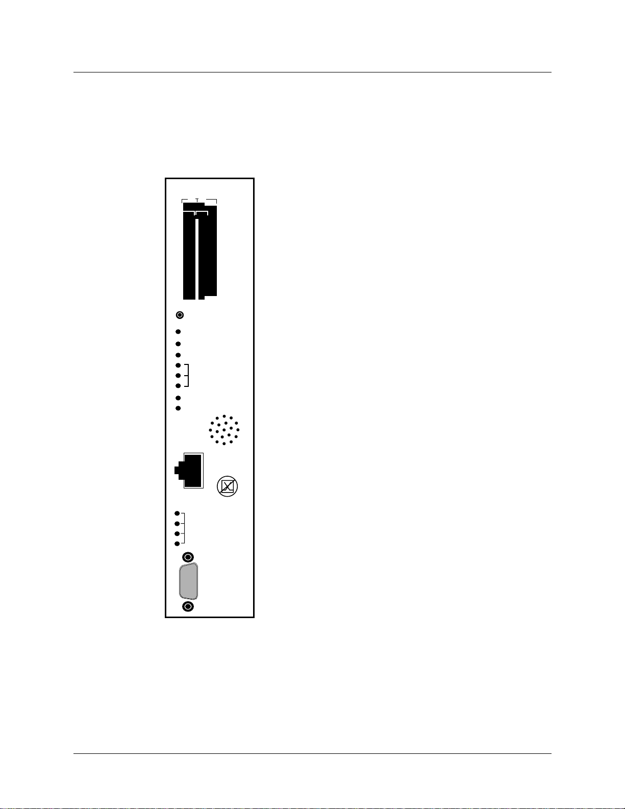
Control board
GRF 400 control board hardware runs the router management software (RMS). RMS is the
communications and control software for the media cards. Other control board components are
the system RAM, internal flash memory, switch hardware, Ethernet connector, and PCMCIA
device slots. The control board is field-replaceable, but not hot swappable.
PCMCIA
B A
RESET
POWER
FAULT
STATUS
ACTIVE
TRANSMIT
RECEIVE
COM BUS
PS1-OK
PS2-OK
100/10
LINK OK
100
XMT ACT
ETHERNET
RCV ACT
•
•
•
•
•
•
•
•
•
RS232
COM1
A hardware reset button, receptacles for Ethernet and RS-232
connections, and power, status and fault LEDs are on the control
board’s faceplate, shown left.
PCMCIA slots can contain an external flash memory device and a
PCMCIA modem attachment.
The system can be reset by depressing the reset button, but a
software command reset is preferable since it saves files and
leaves the system in order.
LEDs provide status for control board and chassis components.
The faceplate speaker functions as a typical PC speaker , it chimes
during system boot, for example. The control board has another
component that sounds an audible alarm when the operating
temperature level is exceeded.
The control board has temperature monitoring (sensor) and
reporting (alarm) capabilities. The router management software
provides a command (temp) to check the current board-surface
operating temperature. If excessive temperature levels are
reached, the router management software triggers the control
board’s audible alarm. If levels are exceeded, the management
software will shut the system down. The management software
also monitors the power supply units, issuing power failure
warnings to the user interface via grconslog if power problems
are detected. The LEDs do not reflect the actual location of power
supplies in the chassis: power supply 2 is on top, power supply 1
is on the bottom.
A 10/100 megabit Ethernet receptacle (autosensing) supports a
connection to the administrative LAN. A set of four LEDs
indicate status (Link OK), activity (XMT ACT, RCV ACT), and
connection rate (if 100 Mbs).
TheVT-100 terminal attaches to the serial port.
Switch control
Each media card is on a switch port. Switch control manages media card requests to connect
through the switch to the switch port occupied by a destination media card. Switch logic
determines if the target port is available and, if it is, enables the connection. A special bus
carries the request and grant traffic for available switch ports.
1-6October, 1998 GRF 400/1600 Getting Started - 1.4 Update 2
Page 29

System memory
Figure 1-5 illustrates the RAM and flash memory components on the GRF control board:
Getting Acquainted with the GRF 400
Overview of the GRF 400 base unit
System RAM
Permanently
reserved for
file system
Control board
CPU
128MB
96
MB
32
MB
---> 256 MB ---> 384 MB ---> 512 MB
+
64
MB
64
MB
Administrative
LAN (de0)
64
MB
64
MB
++
64
MB
PCMCIA
64
MB
Slot A
Disk
Internal flash
device
85MB
Slot B
modem
device options
(g0001)
Figure 1-5. Memory components and options on the control board
RAM The GRF 400 is equipped with a minimum of 128MB of internal RAM, 32MB of
which are permanently reserved for the file system, including logs and configuration files. The
remaining 96MB are used by the operating system and user applications such as GateD.
System memory can be upgraded in 128MB increments up to a total of 512MB, including the
32MB always reserved for the file system. To permit the software to operate in the allocated
memory, certain portions of standard UNIX, such as man page files, are omitted. Man pages
for GRF commands are maintained.
Because file system space is limited, you should configure logging to be done remotely via
syslog or locally to external flash. Additional system memory supports route tables and other
protocol data, and cannot be used for storing logs.
Internal flash The GRF has an internal 85MB ATA flash device from which the system
boots. This memory is available for storing different versions of operating software and site
configurations.
External flash PCMCIA slots on the control board support various sizes of ATA flash
devices. Although external flash can be used to back up and share router configurations among
multiple GRF systems, a GRF cannot boot from an external flash device. Local logging and
dumping to external flash is also supported. The grwrite command writes files from system
RAM to internal flash, grsnapshot copies files between internal and external flash devices.
Commands for flash device management are discussed in the GRF Configuration and
management manual.
PCMCIA devices PCMCIA slot A is used for a portable external flash device. A PCMCIA
modem device can operate in either slot A or B. Instructions for configuring the modem and a
disk device are in chapter 4.
GRF 400/1600 Getting Started - 1.4 Update 2 October, 1998 1-7
Page 30

Getting Acquainted with the GRF 400
Overview of the GRF 400 base unit
Fans
Three intake fans push air across the media cards, control board, and power supplies. Warmed
air exhausts out the side vents next to the power supplies. If the unit is installed in a rack, the
sides of the GRF chassis should not be adjacent to a device in the next rack. Be sure that the
intake vents do not draw in air exhausted by another device. Fans are not swappable. They are
part of the GRF 400 chassis and must be replaced by certified personnel.
Fan “too slow” message
You may occasionally see a message in the /messages log file similar to this:
Jul 20 04:00:25 tn-btvt-1-E0-1 kernel: rmb0: RMB Fan 0 is too slow
This message can be generated when the low-priority task of updating the fan rotation count
has been replaced by a higher-priority communication bus activity. Unless you see it repeated
frequently in a five-minute period, you can ignore it. If the message is repeated, use the grrmb
temp command to check the chassis temperature.
Backplane
The GRF 400 backplane spans the width of the chassis and is fixed in place. The backplane is
not a field replaceable unit.
The backplane supplies power to the media cards and control board. The control board and
media cards exchange configuration and status information through the 80 megabit/second
communications bus located on the backplane.
Communications bus
The communications bus (com bus) is a separate data path for configuration, control,
monitoring functions. This bus connects the control board to the media cards independently of
the switch connection to each card, and is not used for routed data between media cards. Route
table update packets received by the media cards are also sent across the com bus to the router
manager software and do not compete with normal IP data traffic.
Battery
The control board has a small 3V lithium battery to store BIOS CMOS configuration and for
powering the real time clock if the GRF is powered off.
!
Caution: Danger of explosion if the battery is incorrectly replaced. Replace only with the
same or equivalent type recommended by the manufacturer. Dispose of used batteries
according to the manufacturer’s instructions.
Vorsicht: Explosionsgefahr bei unsachgemäßem Austausch der Batterie. Ersatz nur durch
denselben oder einen vom Hersteller empfohlenen gleichwertigen Typ. Entsorgung
gebrauchter Batterien nach Angaben des Herstellers.
Attention: Il y a danger d’explosion s’il y a remplacement incorrect de la batterie.
Remplacer uniquement avec une batterie du même type ou d’un type équivalent recommandé
1-8October, 1998 GRF 400/1600 Getting Started - 1.4 Update 2
Page 31

par le constructeur. Mettre au rebut les batteries usagées conformément aux instructions du
fabricant.
Power supplies
The GRF 400 can use either AC or DC (negative 48VDC) power supplies. GRF systems are
shipped with the power supply installed. Power supplies are housed in open frame drawers for
cooling by the chassis fans. Only qualified personnel can service and replace GRF 400 power
supplies.
Remember that the GRF 400 does not have a power on/off switch. When the power supplies
receive current, the GRF powers on and, since the software is already loaded, immediately
begins to boot.
Redundant units
Two power supplies can be installed for redundancy. When two units are present, both are
active, load-sharing devices. If one fails, the other unit ramps up to provide the full load. Each
power supply has an LED on the control board.
Looking from the cabling end of the chassis, the power supplies are mounted on the left side.
The bottom power supply is numbered 1, and the upper supply is numbered 2. In a
non-redundant system, the single power supply unit can be installed in either 1 or 2, it does not
matter.
Getting Acquainted with the GRF 400
Overview of the GRF 400 base unit
If a unit failure occurs in a redundant system, the failed unit can be hot swapped out. The unit
being removed must be unplugged or disconnected from its AC or DC power source.
Failure notification
If a power supply fails, you will see failure messages on-screen at the user interface. The
/var/log/gr.console log file will also contain related messages. The green PS1-OK or
PS2-OK LED on the control board goes off to indicate a power supply failure. If you do not
already have a replacement unit, order one from Lucent.
GRF 400/1600 Getting Started - 1.4 Update 2 October, 1998 1-9
Page 32

Getting Acquainted with the GRF 400
Description of the AC power supply
Description of the AC power supply
The GRF 400 400W AC power supply provides +5V to all media cards, control board, and
backplane. Remember that the GRF 400 chassis does not have a power on/off switch. When
you plug the AC power supply cord into a live outlet, the GRF powers on and, since the
software is already loaded, immediately begins to boot.
The GRF 400 can be ordered with one or a redundant pair of AC power supply units. The AC
unit is available only from Lucent.
Powering on a GRF 400 power supply is described in Chapter 3.
A note about redundant AC supplies
When the GRF 400 is equipped with redundant AC power supplies, please note the following
when powering on (plugging) or powering off (unplugging) the GRF unit:
Caution: This unit has two power supply cords. For total isolation from electrical shock and
energy hazard, disconnect both supply cords. Care must be taken to correctly connect each
power supply to separate AC power sources and (optional) UPS devices.
Vorsicht: Dieses Gerät hat zwei Netzanschlusskabel. Um das Gerät vollständig von Netz zu
trennen ziehen Sie beide Kabel ab, sonst können Sie einen elektrischen Schlag erhalten.
Achten Sie darauf, daß jedes Stromkabel mit einer separaten Wechselstromquelle und einem
separaten USV-Gerät verbunden wird.
Attention: Cet appareil a deux cordons d’alimentation électrique. Pour une isolation
complète de tout choc électrique et de danger énergétique, débrancher les deux cordons
d’alimentation.
Incompatibilities between AC power supply models
For some time the GRF 400 has been equipped with 400W power supplies manufactured by
Astec.
The standard AC power supply is being switched to a unit manufactured by Artesyn
(previously Zytec). Refer to Figure 1-6 and Figure 1-7 for front panel illustrations of both
types of power supplies.
The Astec and Artesyn power supplies are incompatible. The two models do not consistently
support load sharing between them, and their incompatibilities can mask a unit failure. As a
result, the two models must not be installed together in the same GRF 400 chassis.
This installation requirement is critical in the following situations:
• when a system with a single Astec unit intends to install a second unit for redundancy.
If you intend to add a redundant unit to a GRF 400 with a single Astec unit installed (black
handle), you must switch to two Artesyn units.
• when a system with dual Astec units has a failure and needs a replacement unit.
If you have a failure in a GRF 400 configured with dual Astec units, you must switch to
two Artesyn units.
1-10October, 1998 GRF 400/1600 Getting Started - 1.4 Update 2
Page 33

Getting Acquainted with the GRF 400
Description of the AC power supply
• units might be swapped at sites having multiple GRF 400 units with different power
supplies.
If you swap power supplies, remember you cannot mix models in the same GRF chassis.
Contact your Lucent sales representative to order the appropriate power supply units.
Astec supplies have a black pull handle as shown in Figure 1-6:
Black handle
CAUTION: This unit has two power supply cords. For total isolation from
electrical shock and energy hazard, disconnect both supply cords.
(This label is present only when
a second supply is installed.)
ACHTUNG: Dieses Gerät hat zwei Netzanschlusskabel. Um das Gerät
!
vollständig von Netz zu trennen ziehen Sie beide Kabel ab,
sonst können Sie einen elektrischen Schlag erhalten.
Figure 1-6. Front of Astec AC power supply drawer.
The Artesyn power supply has a silver pull handle as shown in Figure 1-7:
Silver handle
CAUTION: This unit has
two power supply cords.
For total isolation from
electrical shock and
energy hazard, disconnect
both supply cords.
100-240V
ACHTUNG: Dieses Gerät hat zwei
Netzanschlusskabel. Um das Gerät
vollständig von Netz zu trennen ziehen
Sie beide Kabel ab, sonst können Sie
einen elektrischen Schlag erhalten.
ATTENTION: Cet appareil a deux
cordons d’alimentation électrique. Pour
une isolation complète de tout choc
électrique et de danger énergétique,
débrancher les deux cordons
d’alimentation.
(This label is present only when
a second supply is installed.)
Figure 1-7. Front of Artesyn AC power supply drawer.
Note:
When replacing Astec units in a redundant system with Artesyn (previously Zytec) supplies,
the units can be hot swapped, there is no need to power off the GRF unit. Do not leave one of
each type of supply (one Artesyn and one Astec unit) "mixed" in the GRF 400 for an extended
period of time. To keep the GRF 400 up and running, mixing power supplies during a brief hot
swap is acceptable.
GRF 400/1600 Getting Started - 1.4 Update 2 October, 1998 1-11
Page 34

Getting Acquainted with the GRF 400
Description of the 48V DC power supply
Description of the 48V DC power supply
The GRF 400 can be ordered with one or a redundant pair of negative 48V DC power supply
units. The DC unit is available only from Lucent.
Attaching DC supply wiring to the DC power supplies is described in Chapter 3.
The terminals and markings of a GRF 400 DC power supply are shown in Figure 1-8:
-48V
!
SEE INSTRUCTION MANUAL
RETURN
ALARM
Cover area
Figure 1-8. Front of -48V power supply drawer.
Redundant DC supply safety considerations
The notice shown below appears on the lower edge of the GRF 400 DC power supply:
!
SEE INSTRUCTION MANUAL
and refers to the following caution:
If the GRF is equipped with redundant DC power supplies, please note the following when
powering off (disconnecting) the GRF unit:
Caution: This unit has two power inputs. For total isolation from electrical shock and ener gy
hazard, disconnect both power inputs. Care must be taken to correctly connect each power
supply to separate power sources and (optional) UPS devices.
Vorsicht: Dieses Gerät hat zwei Stromeingänge. Um das Gerät vollständig vom Netz zu
trennen, unterbrechen Sie den Anschluß mit beiden Eingängen, sonst können Sie einen
elektrischen Schlag erhalten. Achten Sie darauf, daß jedes Stromkabel mit einer separaten
Wechselstromquelle und einem separaten USV-Gerät verbunden wird.
Attention: Cet appareil a deux sources d’alimentation électrique. Pour une isolation
complète de tout choc électrique et de danger énergétique, débrancher les deux sources
d’alimentation.
1-12October, 1998 GRF 400/1600 Getting Started - 1.4 Update 2
Page 35

Installation preview
Now that you are familiar with the GRF 400, this page gives you a preview of the tasks you
will do to install the GRF, and what the other chapters in this Getting Started manual cover:
1 Rack mount and ground the GRF chassis. (chapter 3) 2 Insert any additional media cards. The GRF is shipped with all ordered media cards
installed, if you have others to install, insert them now. (chapter 3)
3 Attach a VT 100-compatible terminal or laptop PC to the serial port (RS-232) on the GRF
control board. The terminal is used to enter the initial IP configuration information and to
monitor system boot. Later you can connect the GRF to the administrative Ethernet and
disconnect the terminal. (chapter 3)
4 Power on the GRF by plugging in the AC power supply or wiring the DC power supply.
The GRF has no on/off switch, and ships with software already loaded. When you apply
current to the power supplies, the GRF begins to boot. Watch the control board LEDs to
see the status of the system during and after boot. (chapter 3)
Getting Acquainted with the GRF 400
Installation preview
5 The first time a GRF is powered on, a configuration script automatically runs. The script
prompts you to enter the router’s system IP address and host name. You must supply this
information to communicate with the GRF and to later connect the GRF to your
administrative Ethernet. (chapter 4)
The script also prompts you to begin to configure remote logging by setting up a syslog
server. If you choose to configure “local” logging to a PCMCIA device, just press the
<Enter> key at those prompts.
6 Log in as root. Optionally, you can change the preset password for root. (chapter 4) 7 Configure logging, there are several options. Procedures to set up local PCMCIA and
network logging are in this manual. (chapter 4)
Optionally, you can install and configure a PCMCIA modem connection to the GRF.
8 Connect the GRF maintenance Ethernet interface to your site’s administrative LAN. Use
the Ethernet connector on the control board. If you like, you can now disconnect the VT
100 terminal. (chapter 4)
9 Attach the media card cables. (chapter 5)
At the end of this Getting Started manual, you are ready to configure the media card interfaces,
network services, and protocols. This information is covered in the GRF Configuration and
Management manual.
GRF 400/1600 Getting Started - 1.4 Update 2 October, 1998 1-13
Page 36

Getting Acquainted with the GRF 400
Installation preview
1-14October, 1998 GRF 400/1600 Getting Started - 1.4 Update 2
Page 37

Getting Acquainted with the GRF 1600
This chapter describes the components in a GRF 1600 router that you need to be familiar with
as you set up and install the equipment.
At the end of this chapter is a one-page preview of the tasks to set up and install the GRF.
Please read through the list, the tasks are described in subsequent chapters.
After you have completed this introduction to the GRF 1600, go to chapter 3. It contains
information for rack-mounting the GRF 1600 and procedures you use to power on AC and DC
systems.
Chapter 2 covers these topics:
What is the GRF 1600? . . . . . . . . . . . . . . . . . . . . . . . . . . . . . . . . . . . . . . . . . . . . . . . . . 2-2
Which items are included in your system? . . . . . . . . . . . . . . . . . . . . . . . . . . . . . . . . . . 2-3
Site-supplied components . . . . . . . . . . . . . . . . . . . . . . . . . . . . . . . . . . . . . . . . . . . . . . . 2-3
Components you can add. . . . . . . . . . . . . . . . . . . . . . . . . . . . . . . . . . . . . . . . . . . . . . . . 2-3
Upgrading system memory . . . . . . . . . . . . . . . . . . . . . . . . . . . . . . . . . . . . . . . . . . . . . . 2-5
Overview of the GRF 1600 base unit. . . . . . . . . . . . . . . . . . . . . . . . . . . . . . . . . . . . . . . 2-6
2
Description of the AC power supplies . . . . . . . . . . . . . . . . . . . . . . . . . . . . . . . . . . . . . 2-13
Description of the 48VDC power supplies . . . . . . . . . . . . . . . . . . . . . . . . . . . . . . . . . 2-16
Installation preview . . . . . . . . . . . . . . . . . . . . . . . . . . . . . . . . . . . . . . . . . . . . . . . . . . . 2-18
Note: The GRF 1600 replaces the GR-II (GigaRouter) and its attached RMS node as a
high-performance router product.
GRF 400/1600 Getting Started - 1.4 Update 2 October, 1998 2-1
Page 38

Getting Acquainted with the GRF 1600
What is the GRF 1600?
What is the GRF 1600?
The GRF 1600 is a high-performance IP switch designed for high-volume, large-scale public
and private backbone applications. It has these main features:
• Performs Layer-3 switching across 16 gigabits/second aggregate bandwidth
• Supports large suite of routing protocols
• Accommodates 1–16 media cards, available media are ATM OC-3c, ATM OC-12c,
10/100Base-T Ethernet (4- and 8-port), HSSI, HIPPI, SONET OC-3c, and FDDI
• Provides advanced dynamic routing, basic packet filtering, OSPF multicast, SNMP v1,
IPv4
• Accommodates redundant, hot swappable power supplies
• Supports an 1100W AC power supply unit
• Supports a -48VDC power supply (negative 48V)
• Manages 150K-entry route table, batch updating with 20 routes per second
The GRF 1600 chassis can be mounted in a standard 19” rack unit or on a table.
The chassis weighs between 107 and 124 pounds (49–56 kg), depending upon the number of
power supplies installed. Side rails are recommended to be installed in the rack unit before
attempting to insert a GRF 1600. Side rails will help to support the heavy unit as the team
inserts the chassis and fastens it to the rack.
!
Caution: Because of its weight, moving the GRF 1600 into a rack requires a two-person
team.
Vorsicht: Aufgrund seines Gewichts sind zur Installation des GRF 1600 auf dem Regal zwei
Personen erforderlich.
2-2October, 1998 GRF 400/1600 Getting Started - 1.4 Update 2
Page 39

Getting Acquainted with the GRF 1600
Which items are included in your system?
Which items are included in your system?
This section helps you confirm the items in your system.
• Each system includes a GRF 1600 base unit.
• Unit contents vary depending upon the type/number of media cards ordered.
• Software is pre-installed at the factory.
AC power cord
For A C systems, make sure the shipping box contains an AC power cord. If your GRF 1600 has
a redundant AC power supply, you should have two power cords.
• one (two) AC power cords
AC power cord requirements
Use only the power cord included with your product or an equivalent cord:
• North America:
UL listed, CSA certified, type SJT or SVT, 3-conductor, 18AWG minimum
• outside of North America:
Agency-approved for the country of use, cord type H05VVF3G1.5, 3-conductor,
1.5mm2, rated 250V, 16A; plug type suitable for country of use
Site-supplied components
To boot the GRF 1600, you must attach a VT100-compatible terminal directly to the serial
receptacle on the control board, and you must supply:
• a standard RS-232 null modem cable
• a VT100-compatible terminal
Optionally, if you later want to directly connect the GRF to a site LAN, you must supply:
• a cross-over 10Base-T Ethernet cable to connect the LAN to the Ethernet receptacle on the
control board
Components you can add
In addition to media cards, GRF 1600 options you can order from Lucent include:
• 1100W AC power supplies
• a locking clamp for the AC power supply is available from Panel Components
Corporation, P/N 85910051, (515) 673-5000
• negative 48V DC power supplies
• upgrades to internal control board RAM
The GRF 1600 ships with a base of 128MB of RAM. Sites can upgrade to a maximum of
512MB in increments of 128MB, as pairs of 64MB SIMMs.
GRF 400/1600 Getting Started - 1.4 Update 2 October, 1998 2-3
Page 40

Getting Acquainted with the GRF 1600
Components you can add
Memory upgrades may be obtained only from Lucent, do not use other sources.
• ATA disk devices in a PCMCIA slot for system logging and backup
Lucent certifies the following ATA-compliant devices for GRF operation:
– Kingston Datapak 520MB, P/N CT520RM
– Sandisk 175MB Flash, P/N SDP3B
– Sandisk 85MB Flash, P/N SDP3B-85-101
– Aved 85MB Flash, P/N AVEF385MB25ATA501
Lucent offers only the 85 MB Flash directly (GRF-AC-FLASH). Customers may purchase
the other devices through an external source.
• Lucent certifies the following PCMCIA modem for use in a GRF 1600:
– US Robotics/MegaHertz 56K PC Card Modem, model xj5560
2-4October, 1998 GRF 400/1600 Getting Started - 1.4 Update 2
Page 41

Upgrading system memory
Figure 2-1 shows the area of system memory (control board RAM) that can be expanded to
meet site requirements. Memory upgrades are made in 128MB increments up to 512MB.
Getting Acquainted with the GRF 1600
Upgrading system memory
expandable to -->
- system software
- config files
- GateD binary
- log files
- route tables
- ATMP tunnels
- kernel runs
- GateD runs
256MB
RAM
212MB
= expandable area of RAM
--> 384MB
RAM
340MB
--> 512MB
RAM
468MB
Memory
size and
organization
128MB RAM
32MB
(fixed size)
84MB
8-12MB
(fixed size)
Figure 2-1. Expandable area of system memory
This chart provides general guidelines for memory required in different routing environments.
Although the figures assume BGP peers with 50K route entries, additional memory may be
required for higher average numbers of routes per BGP peer.
If the GRF is to support dynamic routing or ATMP home agents and mobile nodes, upgrade to
at least 256MB. In environments where large numbers of routes are advertised, upgrade to
512MB.
Customer
profile
Amount of
control
board
memory
needed
Space for
dynamic
routing,
ATMP
tables
Route
entries
on
media
card
Route
entries in
dynamic
routing
database
Typical
numbe
r of
peer
sessions
Static routing:
(in high-performance
environment)
Small POP 256MB 212MB 150K Typical
128MB 84MB 150K Typical
number:
35,800
0
3
number:
199,000
Medium POP /
ISP backbone
384MB 340MB 150K Typical
number:
9
362,000
Large POP /
Exchange point /
Route reflection server
512MB 468MB 150K Typical
number:
521,000
12
GRF 400/1600 Getting Started - 1.4 Update 2 October, 1998 2-5
Page 42

Getting Acquainted with the GRF 1600
Overview of the GRF 1600 base unit
Overview of the GRF 1600 base unit
Figure 2-2 shows the GRF 1600 base unit from the front of the cabinet. All cables and power
cords attach at the rear panel. The GRF 1600 chassis is organized into three sections.
In the top section, a pair of high-speed impeller fans draw air up through the media cards and
exhaust it out vents on each side of the chassis. These vents must not be obstructed in an y w ay.
When you install the GRF, you must provide a minimum of 6 inches of clearance on the sides
of the unit and keep the front and back clear of obstruction. The backplane and system cards
are installed in the middle section, above the air intake plenum. Intake vents are at each chassis
side and front. Power supplies are in the bottom section. Their internal fans e xhaust air out the
lower chassis front and require a minimum of six inches of clearance.
Note the hand holds on the chassis sides, these are especially helpful when installing the GRF
in a rack.
GRF 1600
Lucent Technolo gies
Impeller fans
Fan exhaust
vent
Figure 2-2. GRF 1600 base unit and component areas (front view)
Media cards,
control board,
switch board
Backplane
Power supply
intake air
Hand hold
Power supplies
Power supply
fan exhaust
vent
(g0143)
2-6October, 1998 GRF 400/1600 Getting Started - 1.4 Update 2
Page 43

HIPPI
D
E
S
T
I
N
A
T
I
O
N
S
O
U
R
C
E
Getting Acquainted with the GRF 1600
Overview of the GRF 1600 base unit
The rear panel of the GRF 1600 chassis is shown in Figure 2-3. At the top is a fan tray that
houses a pair of motorized impeller fans, the tray is field-replaceable as a single unit.
The top and bottom of the media card section are open grids through which the fans draw air
through the chassis air intake vents. The media cards slide in along the guide in each slot and
plug into their connector on the backplane. Solid vertical partitions separate the control board
and the switch board from the media cards.
Cable harness
Fan tray
Control board
PCMCIA slots A, B
CONTROL
••
••
••
••
••
•
•
•
•
B A
•
•
•
•
•
BOARD
PWR
STATUS
RCV
COM BUS
FAN TEMP
FAULT
PS1
RESET
•
•
•
LINK OK
100
XMT ACT
RCV ACT
ETHERNET
•
RS232
•
•
COM1
•
•
SWITCH
BOARD
PCMCIA
ACT
XMT
PS2
•
•••
•
•
•
•
•
•
•
•
•
•
ATM
A
B
ATM
OC-3c
3c
PWR
FAULT
STAT 0
STAT1
SM
RCV
XMT
LINK
RCV
XMT
LINK
ATM
12c
ATM
OC-12C
SM
PWR
FAULT
STAT 0
STAT1
RCV
XMT
LINK
LASER
ATM
OC-12c
SM/IR
CLASS 1\
LASER
PRODUCT
KLASSE 1
LASER
PRODUKT
FDDI
PWR
S
PWR
T
STAT
01
A
DST
T
SRC
DST
SRC
RX
TX
A
0
TRX
B
0
A
1
TRX
B
1
Ethernet
8-port
Ethernet
SONET
4-port
7
6
5
4
3
3
2
2
1
1
0
0
HSSI
3c
PWR
FAULT
STAT 0
STAT1
STAT2
PWR
FAULT
STAT 0
STAT1
RCV
XMT
LINK
A
RCV
XMT
LINK
B
A
B
Switch board
Reset button
Speaker
Ethernet LAN
Vertical bulkhead
Chassis air intake
vent
Wrist strap ground
Locking tab
Sliding plate finger lift
AC receptacle
Power supply 2
drawer (PS2)
Power supply fan
intake
Rack ground
Power supply 1
drawer (PS1)
Figure 2-3. Rear panel view of GRF 1600
Two ground connectors are on the right edge of the chassis, the upper is for a wrist strap and
the lower is for the rack ground.
The power supply compartment is completely separate from the rest of the chassis. Each power
supply is in an enclosed drawer and is cooled by an internal fan. A locking tab prevents the
drawer from being opened accidentally when the AC cord is plugged into the unit. The PS1 or
PS2 LED on the control board lights to indicate a problem with a specific power supply.
GRF 400/1600 Getting Started - 1.4 Update 2 October, 1998 2-7
Page 44

Getting Acquainted with the GRF 1600
Overview of the GRF 1600 base unit
Media cards
Note: To operate properly, a GRF 1600 requires a minimum of two media cards installed.
Also, a face plate cover must be installed in any unused slot to maintain cooling flows.
The GRF 1600 has 16 media card slots, 0–15, a control board, and a switch board.Slots are
numbered left to right as shown in Figure 2-4, the control board is always 66:
Backplane
Media cards:
Slot numbers:
Figure 2-4. Top view of GRF 1600 chassis with slots numbered
Chassis fans
Two motorized impeller fans cool the chassis, excluding the power supply compartment. The
fans operate in tandem. At start-up, both fans operate at 100% of RPM capability. Gradually
each fan slows down so that, in normal conditions, each fan operates at 50% speed. When the
GRF is plugged in, you can hear the changes in fan speeds. Tachometers on each fan unit
ensure steady, sufficient airflow. When a tachometer detects that a fan is dropping below the
50% rate, it causes a signal to the other fan to speed up. When a problem occurs with either fan,
the control board “FAN” LED lights. You can replace the fan tray on site, contact Lucent to
order a replacement.
The amount of time the GRF 1600 can operate with a failed fan depends upon the number of
installed media cards and the ambient air temperature. The temperature sensor on the control
board shuts the GRF down if the operating temperature is exceeded.
A procedure to exchange the fan trays is in the “Management Tasks” chapter of the GRF
Configuration and Management manual.
0 1 2 3 4 5 6 7 8 9 10 11 12 13 14 15
Control board
66
Switch board
2-8October, 1998 GRF 400/1600 Getting Started - 1.4 Update 2
Page 45

Control board
GRF 1600 control board hardware runs the router management software (RMS). RMS is the
communications and control software for the media cards.
Other control board components are the system RAM, internal flash memory, maintenance
Ethernet connector, and PCMCIA device slots. The control board is field-replaceable, but not
hot swappable.
Getting Acquainted with the GRF 1600
Overview of the GRF 1600 base unit
••
••
••
••
••
•
•
•
•
PCMCIA
B A
PWR
STATUS
RCV
COM BUS
FAN TEMP
FAULT
PS1
RESET
100/10
LINK OK
100
XMT ACT
ETHERNET
RCV ACT
•
•
RS232
•
•
COM1
•
PCMCIA
ACT
XMT
PS2
A hardware reset button, receptacles for maintenance Ethernet
and RS-232 connections, and power, fan, status and fault LEDs
are on the board’s faceplate, shown left.
PCMCIA slots can contain an external flash memory device and a
PCMCIA modem attachment.
LEDs provide status for control board and chassis components.
The system can be reset by depressing the reset button, but a
software command reset is preferable since it saves files and
leaves the system in order.
The faceplate speaker functions as a typical PC speaker , it chimes
during system boot, for example. The control board has another
component that sounds an audible alarm when the operating
temperature level is exceeded.
The control board has temperature monitoring (sensor) and
reporting (alarm) capabilities. The router management software
provides a command (temp) to check the current board-surface
operating temperature. If excessive temperature levels are
reached, the router management software triggers the control
board’s audible alarm. If levels are exceeded, the management
software will shut the system down. The management software
also monitors the power supply units, issuing power failure
warnings to the user interface via grconslog if power problems
are detected.
A 10/100 megabit Ethernet receptacle (autosensing) supports a
connection to the administrative LAN. A set of four LEDs
indicate status (Link OK), activity (XMT ACT, RCV ACT), and
connection rate (if 100 Mbs).
TheVT-100 terminal attaches to the serial port.
GRF 400/1600 Getting Started - 1.4 Update 2 October, 1998 2-9
Page 46

Getting Acquainted with the GRF 1600
Overview of the GRF 1600 base unit
Switch board
The 16x16 switch chip and switch control logic reside on the GRF 1600 switch board. The
switch board is field-replaceable, but not hot swappable. It is installed to the right of the
control board in the central chamber.
Switch control
Each media card is on a switch port. Switch control manages media card requests to connect
through the switch to the switch port occupied by a destination media card. Switch logic
determines if the target port is available and, if it is, enables the connection. A special bus
carries the request and grant traffic for available switch ports.
Battery
The control board has a small 3V lithium battery to store BIOS CMOS configuration and for
powering the real time clock if the GRF is powered off.
!
Caution: Danger of explosion if battery is incorrectly replaced. Replace only with the same
or equivalent type recommended by the manufacturer. Dispose of used batteries according to
the manufacturer’s instructions.
Vorsicht: Explosionsgefahr bei unsachgemäßem Austausch der Batterie. Ersatz nur durch
denselben oder einen vom Hersteller empfohlenen gleichwertigen Typ. Entsorgung
gebrauchter Batterien nach Angaben des Herstellers.
Attention: Il y a danger d’explosion s’il y a remplacement incorrect de la batterie.
Remplacer uniquement avec une batterie du même type ou d’un type équivalent recommandé
par le constructeur. Mettre au rebut les batteries usagées conformément aux instructions du
fabricant.
Backplane
The GRF 1600 backplane spans the width of the chassis and is fixed in place. The backplane is
not a field replaceable unit.
The backplane supplies power to the media cards and control board. The control board and
media cards exchange configuration and status information through the 80 megabit/second
communications bus located on the backplane.
Communications bus
The communications bus (com bus) is a separate data path for configuration, control,
monitoring functions. This bus connects the control board to the media cards independently of
the switch connection to each card, and is not used for routed data between media cards. Route
table update packets received by the media cards are also sent across the com bus to the router
manager software and do not compete with normal IP data traffic.
2-10October, 1998 GRF 400/1600 Getting Started - 1.4 Update 2
Page 47

System memory
Figure 2-5 illustrates the RAM and flash memory components on the GRF control board:
Getting Acquainted with the GRF 1600
Overview of the GRF 1600 base unit
System RAM
Permanently
reserved for
file system
Control board
CPU
128MB
96
MB
32
MB
---> 256 MB ---> 384 MB ---> 512 MB
+
64
MB
64
MB
Administrative
LAN (de0)
64
MB
64
MB
++
64
MB
PCMCIA
64
MB
Slot A
Disk
Internal flash
device
85MB
Slot B
modem
device options
(g0001)
Figure 2-5. Memory components and options on the control board
RAM The GRF 1600 is equipped with a minimum of 128MB internal RAM, 32MB of which
are permanently reserved for the file system, including logs and configuration files. The
remaining 96MB are used by the operating system and user applications such as GateD.
System memory can be upgraded in 128MB increments up to a total of 512MB, including the
32MB always reserved for the file system. To permit the software to operate in the allocated
memory, certain portions of standard UNIX, such as man page files, are omitted. Man pages
for GRF commands are maintained.
Because file system space is limited, you should configure logging to be done remotely via
syslog or locally to external flash. Adding system memory only supports route tables and other
protocol data, additional memory cannot be used for storing logs. Chapter 4 describes options
for configuring external logging.
Internal flash The GRF has an internal 85MB ATA flash device from which the system
boots. This memory is available for storing different versions of operating software and site
configurations.
External flash PCMCIA slots on the control board support various sizes of ATA flash
devices. Although external flash can be used to back up and share router configurations among
multiple GRF systems, a GRF cannot boot from an external flash device. Local logging and
dumping to external flash is also supported. The grwrite command writes files from system
RAM to internal flash, grsnapshot copies files between internal and external flash devices.
Commands for flash device management are discussed in the GRF Configuration and
management manual.
PCMCIA devices PCMCIA slot A is used for a portable external flash device. PCMCIA
modem devices can operate in either slot A or B. Instructions for installing and configuring the
modem and a disk device are in chapter 4.
GRF 400/1600 Getting Started - 1.4 Update 2 October, 1998 2-11
Page 48

Getting Acquainted with the GRF 1600
Overview of the GRF 1600 base unit
Power supply options
The GRF 1600 uses either AC or DC (negative 48VDC) power supplies. GRF systems are
shipped with the power supply installed. Power supplies are housed at the bottom of the chassis
in self-contained, self-cooled drawers. Visible from the cabling end of the chassis, power
supply 1 (PS1 LED) is on the left, power supply 2 (PS2 LED) is on the right. In a
non-redundant system, the single power supply unit can be installed in either 1 or 2, it does not
matter. Only qualified personnel can service and replace GRF 1600 power supplies.
Two power supplies can be installed for redundancy. When two units are present, both are
active, load-sharing devices. If one fails, the other unit ramps up to provide the full load. Each
power supply has an LED (PS1, PS2) on the control board. If a unit failure occurs in a
redundant system, the failed unit can be hot swapped out. The unit being removed must be
unplugged or disconnected from its AC or DC power source.
Each power supply has an internal fan to cool that unit. Air is drawn in at the drawer front and
exhausted out the rear of the drawer. If a power supply overheats, its internal regulators will
shut the unit down.
Power supply failure notification
If a power supply fails, you will see failure messages on-screen at the user interface. The
gr.console log file will also contain related messages. The amber PS1 or PS2 LED on the
GRF 1600 control board will come on to indicate a power supply failure. If you do not already
have a replacement unit, order one from Lucent.
Warning: A failed power supply must be replaced by certified personnel only.
Warnung: Das Netzteil darf nur von einer Fachkraft ausgewechselt werden.
2-12October, 1998 GRF 400/1600 Getting Started - 1.4 Update 2
Page 49

Getting Acquainted with the GRF 1600
Description of the AC power supplies
Description of the AC power supplies
The GRF 1600 1100W AC power supply provides +48V to the fans and +5.0V to all media
cards, control board, switch board, and backplane. Remember that the GRF 1600 chassis does
not have a power on/of f switch. When you plug the AC po wer supply cord into a liv e outlet, the
GRF powers on and, since the software is already loaded, immediately begins to boot.
Figure 2-6 shows the front of an AC power supply drawer and its locking tab components.
Locking tab in down (unlocked) position
When locking tab is down,
power plug cannot be
inserted
Power supply
air intake fan
CAUTION: This unit has two power supply cords. For total isolation from electrical shock and energy hazard, disconnect both supply cords.
ACHTUNG: Dieses Gerät hat zwei Netzanschlusskabel. Um das Gerät vollständig von Netz zu trennen ziehen Sie beide Kabel ab, sonst können Sie einen
elektrischen Schlag erhalten.
ATTENTION: Cet appareil a deux cordons d’alimentation électrique. Pour une isolation complète de tout choc électrique et de danger énergétique, débrancher les deux
cordons d’alimentation.
100-240V
Warning label is placed face-up on the horizontal edge below the intake fan.
Locking tab in up (locked) position
Drawer handle
Sliding plate
Finger lift
When locking tab is up,
power plug can be inserted
Figure 2-6. Front of GRF 1600 AC power supply drawer and locking tab
GRF 400/1600 Getting Started - 1.4 Update 2 October, 1998 2-13
Page 50

Getting Acquainted with the GRF 1600
Description of the AC power supplies
AC drawer locking tab
The A C po wer supply drawers ha ve a locking mechanisn that pre vents an yone from removing a
drawer while the unit has a power cord plugged in. Refer to the diagram below.
Before you plug the cord into the power supply, you can see that a plate covers part of the AC
receptacle. You can easily slide this plate up to insert the cord. The locking tab stays up in the
locked position and prevents the drawer from being pulled out while the power cord is plugged
in.
The locking tab is at the top edge of the sliding plate. Immediately below the sliding plate and
at either side of the receptacle are two small screws. These screws attach the AC receptacle to
the drawer front. They also are used to attach a power cord clamp. The screws can be
untightened 3 or 4 turns to allow the clamp to slide under, but they should never be fully
removed.
Drawer handle
Sliding plate
Finger lift
When locking tab is up,
power plug can be inserted
How to obtain a clamp
Lucent does not supply cord clamps. Clamps are available from the Panel Components
Corporation, P/N 85910051, at (515) 673-5000.
AC power supply safety considerations
Locking tab in up (locked) position
Caution: The power supplies contain hazardous voltages and energy levels.
• Do not attempt to service yourself. Refer all servicing to qualified personnel.
• Double-pole/neutral fusing.
Vorsicht: In den Netzteilen liegen Hochspannung und gefährliche Energiepegel an.
• Versuchen Sie nicht, das Gerät selbst zu warten. Alle Reparaturarbeiten sind von
Fachkräften auszuführen.
• Zweipolige/Neutralleiter-Sicherung
2-14October, 1998 GRF 400/1600 Getting Started - 1.4 Update 2
Page 51

Getting Acquainted with the GRF 1600
Description of the AC power supplies
Redundant AC supply safety considerations
If the GRF is equipped with redundant AC power supplies, please note the following when
powering on (plugging in) and powering off (unplugging) the GRF unit:
Caution: This unit has two power supply cords. For total isolation from electrical shock and
energy hazard, disconnect both supply cords. Care must be taken to correctly connect each
power supply to separate AC power sources and (optional) UPS devices.
Vorsicht: Dieses Gerät hat zwei Netzanschlusskabel. Um das Gerät vollstandig von Netz zu
trennen ziehen Sie beide Kabel ab, sonst können Sie einen elektrischen Schlag erhalten.
Achten Sie darauf, daß jedes Stromkabel mit einer separaten Wechselstromquelle und einem
separaten USV-Gerät verbunden wird.
Attention: Cet appareil a deux cordons d’alimentation électrique. Pour une isolation
complète de tout choc électrique et de danger énergétique, débrancher les deux cordons
d’alimentation.
Label requirement
The warning label shown in Figure 2-7 is required when a second power supply is installed in a
pre-existing system to provide redundancy. When a GRF is shipped with a single power supply,
this label is not on the power supply unit. If a customer orders a redundant power supply, a set
of labels is included, along with instructions to attach a label to each unit.
CAUTION: This unit has two power supply cords. For total isolation from electrical shock and energy hazard, disconnect both supply cords.
ACHTUNG: Dieses Gerät hat zwei Netzanschlusskabel. Um das Gerät vollständig von Netz zu trennen ziehen Sie beide Kabel ab, sonst können Sie einen
elektrischen Schlag erhalten.
100-240V
ATTENTION: Cet appareil a deux cordons d’alimentation électrique. Pour une isolation complète de tout choc électrique et de danger énergétique, débrancher les
deux cordons d’alimentation.
Figure 2-7. Warning label required for redundant supplies
The label is actually attached to the top edge of the fastening knob compartment at the bottom
of the unit, facing upwards.
Minimum media card load requirement
Redundant GRF 1600 power supplies require a minimum load installed equal to two media
cards. If the minimum media card load is not met, the supplies may generate false power
supply failure messages. While the power supply units are not damaged during this condition,
misleading error messages may be logged in
/var/log/grconsole.log.
When redundant power supplies are installed in a GRF 1600 chassis, you must keep at least
two media cards inserted to meet the minimum load requirement. Minimum load can be
problematical when power supplies are operating in the redundant or current share mode,
particularly on high current output supplies. It is recommended that the GRF 1600 only be
operated with at least two media cards installed.
GRF 400/1600 Getting Started - 1.4 Update 2 October, 1998 2-15
Page 52

Getting Acquainted with the GRF 1600
Description of the 48VDC power supplies
Description of the 48VDC power supplies
The GRF 1600 1100W DC power supply provides +48V to the fans and +5.0V to all media
cards, and the control board, switch board, and backplane. Directions for attaching DC input
wiring to the DC power supply are in chapter 3.
The GRF 1600 does not have a chassis-based power switch. Instead, each DC power supply
has its own on/off switch. You cannot put the switch to on unless the power supply drawer is
properly inserted into the chassis. The DC drawer has a locking tab that prevents the drawer
from being pulled out while the switch is on. You must switch the power off and drop the
locking tab down before you can remove a power supply. Refer to Figure 2-8.
On / off switch
is locked off
Locking tab is in down (drawer unlocked) position
Power supply
air intake fan
Locking tab in up (drawer locked) position
Drawer handle
Finger lift
Power supply is locked in place,
switch can be on
Figure 2-8. Front panel of GRF 1600 DC power supply
2-16October, 1998 GRF 400/1600 Getting Started - 1.4 Update 2
Page 53

Getting Acquainted with the GRF 1600
Description of the 48VDC power supplies
DC drawer locking tab
The DC power supply drawers have a locking mechanisn that prevents anyone from removing
a drawer while the unit is powered on. Refer to Figure 2-8.
The locking tab is at the top edge of the sliding plate. When the power switch is on, the locking
tab stays up in the locked position and prevents the drawer from being pulled out. When the
power is switched off, the tab drops down and the power supply drawer can be removed.
DC power supply safety considerations
Caution: The power supplies contain hazardous voltages and energy levels.
• Do not attempt to service yourself. Refer all servicing to qualified personnel.
Vorsicht: In den Netzteilen liegen Hochspannung und gefährliche Energiepegel an.
• Versuchen Sie nicht, das Gerät selbst zu warten. Alle Reparaturarbeiten sind von
Fachkräften auszuführen.
Redundant DC supply safety considerations
If the GRF is equipped with redundant DC power supplies, please note the following when
powering on and powering off the GRF unit:
Caution: This unit has two power inputs. For total isolation from electrical shock and ener gy
hazard, disconnect both supply inputs. Care must be taken to correctly connect each power
supply to separate AC power sources and (optional) UPS devices.
Vorsicht: Dieses Gerät hat zwei Stromeingänge. Um das Gerät vollständig vom Netz zu
trennen, unterbrechen Sie den Anschluß mit beiden Eingängen, sonst können Sie einen
elektrischen Schlag erhalten. Achten Sie darauf, daß jedes Stromkabel mit einer separaten
Wechselstromquelle und einem separaten USV-Gerät verbunden wird.
Attention: Cet appareil a deux sources d’alimentation électrique. Pour une isolation
complète de tout choc électrique et de danger énergétique, débrancher les deux sources
d’alimentation.
Minimum media card load requirement
Redundant GRF 1600 power supplies require a minimum load installed equal to two media
cards. If the minimum media card load is not met, the supplies may generate false power
supply failure messages. While the power supply units are not damaged during this condition,
misleading error messages may be logged in /var/log/grconsole.log.
When redundant power supplies are installed in a GRF 1600 chassis, you must keep at least
two media cards inserted to meet the minimum load requirement. Minimum load can be
problematical when power supplies are operating in the redundant or current share mode,
particularly on high current output supplies. It is recommended that the GRF 1600 only be
operated with at least two media cards installed.
GRF 400/1600 Getting Started - 1.4 Update 2 October, 1998 2-17
Page 54

Getting Acquainted with the GRF 1600
Installation preview
Installation preview
Now that you are familiar with the GRF 1600, this page gives you a preview of the tasks you
will do to install the GRF, and what the other chapters in this Getting Started manual cover:
1 Rack mount and ground the GRF chassis. (chapter 3) 2 Insert any additional media cards. The GRF is shipped with all ordered media cards
installed, if you have others to install, insert them now. (chapter 3)
3 Attach a VT 100-compatible terminal or laptop PC to the serial port (RS-232) on the GRF
control board. The terminal is used to enter the initial IP configuration information and to
monitor system boot. Later you can connect the GRF to the administrative Ethernet and
disconnect the terminal. (chapter 3)
4 Power on the GRF by plugging in the AC power supply or wiring the DC power supply.
The GRF has no on/off switch, and ships with software already loaded. When you apply
current to the power supplies, the GRF begins to boot. Watch the control board LEDs to
see the status of the system during and after boot. (chapter 3)
5 The first time a GRF is powered on, a configuration script automatically runs. The script
prompts you to enter the router’s system IP address and host name. You must supply this
information to communicate with the GRF and to later connect the GRF to your
administrative Ethernet. (chapter 4)
The script also prompts you to begin to configure remote logging by setting up a syslog
server. If you choose to configure “local” logging to a PCMCIA device, just press the
<Enter> key at those prompts.
6 Log in as root. Optionally, you can change the preset password for root. (chapter 4) 7 Configure logging, there are several options. Procedures to set up local PCMCIA and
network logging are in this manual. (chapter 4)
Optionally, you can install and configure a PCMCIA modem connection to the GRF.
8 Connect the GRF maintenance Ethernet interface to your site’s administrative LAN. Use
the Ethernet connector on the control board. If you like, you can now disconnect the VT
100 terminal. (chapter 4)
9 Attach the media card cables. (chapter 5)
At the end of this Getting Started manual, you are ready to configure the media card interfaces,
network services, and protocols. This information is covered in the GRF Configuration and
Management manual.
2-18October, 1998 GRF 400/1600 Getting Started - 1.4 Update 2
Page 55

Rack Mount and Power On Procedures
Chapter 3 describes how to rack mount and power on the GRF routers, including both AC and
DC power supplies. The first half covers the GRF 400, the second half covers the GRF 1600.
GRF set up is organized so that you attach media cables after power on and watch the progress
of the control board and media card LEDs for indications of normal or error conditions.
Chapter 3 includes these topics:
Rack mounting the GRF 400 . . . . . . . . . . . . . . . . . . . . . . . . . . . . . . . . . . . . . . . 3-2
Inserting a media card . . . . . . . . . . . . . . . . . . . . . . . . . . . . . . . . . . . . . . . . . . . . 3-4
Attaching a VT-100 terminal . . . . . . . . . . . . . . . . . . . . . . . . . . . . . . . . . . . . . . . 3-6
Powering on the GRF 400 . . . . . . . . . . . . . . . . . . . . . . . . . . . . . . . . . . . . . . . . . 3-7
Interpreting GRF 400 control board LEDs . . . . . . . . . . . . . . . . . . . . . . . . . . . . 3-8
Applying AC power to the GRF 400 . . . . . . . . . . . . . . . . . . . . . . . . . . . . . . . . . 3-9
Applying DC power to the GRF 400 . . . . . . . . . . . . . . . . . . . . . . . . . . . . . . . . 3-11
Powering off a GRF 400 . . . . . . . . . . . . . . . . . . . . . . . . . . . . . . . . . . . . . . . . . 3-15
3
Rack mounting the GRF 1600 . . . . . . . . . . . . . . . . . . . . . . . . . . . . . . . . . . . . . 3-16
Inserting a media card . . . . . . . . . . . . . . . . . . . . . . . . . . . . . . . . . . . . . . . . . . . 3-19
Attaching a VT-100 terminal . . . . . . . . . . . . . . . . . . . . . . . . . . . . . . . . . . . . . . 3-21
Powering on the GRF 1600 . . . . . . . . . . . . . . . . . . . . . . . . . . . . . . . . . . . . . . . 3-22
Interpreting GRF 1600 control board LEDs . . . . . . . . . . . . . . . . . . . . . . . . . . 3-23
Applying AC power to the GRF 1600 . . . . . . . . . . . . . . . . . . . . . . . . . . . . . . . 3-24
Applying DC power to the GRF 1600 . . . . . . . . . . . . . . . . . . . . . . . . . . . . . . . 3-27
Powering off a GRF 1600 . . . . . . . . . . . . . . . . . . . . . . . . . . . . . . . . . . . . . . . . 3-32
Note: The GRF 400 and GRF 1600 are static sensitive. An ESD wrist strap must be worn
when you move or otherwise touch the chassis. Each chassis has a wrist strap ground site for
connecting your wrist strap.
GRF 400
GRF 1600
Wrist strap grounding sites
GRF 400/1600 Getting Started - 1.4 Update 2 October, 1998 3-1
Page 56

Rack Mount and Power On Procedures
Rack mounting the GRF 400
Rack mounting the GRF 400
Before you begin installing the GRF 400, make sure you have these items:
– A VT-100 terminal to attach to the control board RS-232 port
– A locally-connected host or workstation that can ping the GRF
– Media cables appropriate to the media cards that were ordered
– If applicable, any media cards that shipped separately
Servicing clearances
Media cards and power supply drawers are 16 inches long. You need three feet of working
space to access and remove hot-swappable components at the GRF 400 cable panel.
Power and ground requirements
!
Caution: If using a power strip or similar supply, make sure the power requirements of the
chassis, plus the cumulative power draw of any other equipment in the rack, do not overload
the supply circuit.
Vorsicht: Wird ein Sammelstecker oder ähnlicher Netzanschluß verwendet, ist darauf zu
achten, daß die Stromerfordernisse des Rahmens gemeinsam mit dem kumulativen
Stromverbrauch anderer Geräte auf dem Regal den Versorgungsschaltkreis nicht überbelasten.
Warning: For safe operation, this equipment must be properly grounded.
– The chassis should be reliably earth grounded to the rack equipment.
– This earth ground connection must be maintained when supply connection is other
than direct connection to the branch circuit.
Warnung: Zur Gewährleistung eines sicheren Betriebs muß dieses Gerät vorschriftsmäßig
geerdet sein.
– Der Geräterahmen muß richtig am Regalbauteil geerdet sein.
– Dieser Masseanschluß muß bewahrt werden, wenn die Stromversorgung nicht direkt
über den Anschluß an den Abzweigstromkreis erfolgt.
3-2October, 1998 GRF 400/1600 Getting Started - 1.4 Update 2
Page 57

Rack-mounting requirements
If you are rack-mounting the GRF 400 base unit:
– Always stack the rack from the bottom up to ensure a stable and safe rack.
– The installation of GRF 400 and other units within the rack should not reduce the air
flow within the rack. The maximum recommended ambient temperature for the GRF
400 is 40˚ C (104˚ F).
– Make sure you have a two-unit air gap for cooling and cables between the GRF and
any other equipment installed in the rack.
– Determine that the cumulative power requirements of the GRF 400 plus other
equipment in the rack do not overload the rack supply circuit and/or wiring.
Ventilation requirements
When installing, please consider the location of the GRF in relation to other devices located in
an adjacent rack. Ensure that the GRF’s air intake is not drawing directly upon heated air from
another unit. Figure 3-1 shows air intake and exhaust areas. When you install the GRF, you
must provide six to ten inches of side clearance.
Rack Mount and Power On Procedures
Rack mounting the GRF 400
Heated air
Figure 3-1. Air intake and exhaust areas of the GRF 400
Ventilation must comply with these requirements:
– The installation of the GRF 400 and other units within the rack should not reduce the
– Make sure you have a two-unit air gap for cooling and cables between the GRF and
What to do next...
If you have media cards that are not inserted in the GRF, insert them now. Go on to the next
section, “Inserting a media card.”
Intake fans
Ambient air
air flow within the rack. The maximum recommended ambient temperature for the
GRF is 40˚ C (104˚ F).
any other equipment in the rack.
With the chassis securely in place and media cards inserted, the next step is to attach a terminal
to the GRF. Go to the section “Attaching a VT-100 terminal.”
GRF 400/1600 Getting Started - 1.4 Update 2 October, 1998 3-3
Page 58

Rack Mount and Power On Procedures
Inserting a media card
Inserting a media card
Note: To operate properly, a GRF 400 should have at least one media card installed.
Note: Also, a face plate cover must be installed in any unused slot to maintain cooling flows.
Media cards are actually two logic boards joined to make a single component. As shown in
Figure 3-9, the smaller board on the right is the serial interface, also called the serial daughter
card. The larger one on the left is the media board and has the network ports. Together they
comprise a GRF media card. The GRF 400 and 1600 use the same media cards.
The media card serial and part numbers are printed at the lower edge of the card, near the
bottom finger grip/extractor.
Ports
ATM
3c
Media board
A
B
ATM
OC-3c
SM
Serial/rev
number area
Serial
daughter
card
Horizontally level for GRF 400
3c
ATM
A
Top Bottom
SM
ATM
OC-3c
B
Vertically
upright
for
GRF
1600
(g0143)
Figure 3-2. Media card components
The boards are joined by two 100-pin connectors and reinforcing plates. Even so, this joint
retains some flex and must be carefully supported, especially when inserting the media card
into a chassis.
Warning: The backplanes of both the GRF 400 and the GRF 1600 contain hazardous energy
levels.
When replacing a media card, remove only one card at a time. Removing more than one
card will expose the operator to this energy hazard.
Warnung: An den Rückwandplatinen des GRF 400 und GRF 1600 liegen gefährliche
Hochspannungen ab.
Zum Auswechseln der Medienkarte je weils nur eine Karte entfernen. Bei zwei gleichzeitig
entfernten Karten ist der Bediener gefährlichen Spannungen ausgesetzt.
ATM
3c
A
B
ATM
OC-3c
SM
3-4October, 1998 GRF 400/1600 Getting Started - 1.4 Update 2
Page 59

ESD requirements
Rack Mount and Power On Procedures
Inserting a media card
!
Caution: GRF media cards are hot swappable and can be installed when the GRF is running.
However, media card are highly susceptible to damage from electrostatic discharge, you must
wear a grounded, conductive wrist strap anytime you handle a media card.
W ear a grounded, conducti ve wrist strap when remo ving, replacing, and/or handling indi vidual
electronic components. Make sure the metallic elements in the band directly touch your
exposed skin.
GRF 1600
Insertion procedure
1 When you are properly grounded, remove the media card from its anti-static container. 2 Hold the media card with the network ports facing you.
GRF 400
Turn the card horizontal, the top of the media card should be on the left, the bottom of the
card should be on the right. As you start, make sure you visually identify the left and right
guide pair for this particular slot.
Keeping the media card horizontally level, insert the card fully into the slot, you will feel
the card joining with the 100-pin connector on the backplane.
GRF 400
Wrist strap grounding sites
3 When fully inserted, the card’s face plate should be flush against the chassis back panel.
Note: Do not force the card into the slot. Doing so can damage the card or slot connector.
4 Tighten the screws at each end of the face plate.
GRF 400/1600 Getting Started - 1.4 Update 2 October, 1998 3-5
Page 60

Rack Mount and Power On Procedures
Attaching a VT-100 terminal
Attaching a VT-100 terminal
You must connect the VT-100 compatible terminal to the control board’s RS-232 serial port
BEFORE you power on the GRF. After the system boots, you will enter system IP and host
name configuration information in the first time power on script from the terminal. This task is
described in chapter 4.
You can stay at the terminal to perform the rest of the system configuration or you can connect
the GRF to the administrative Ethernet LAN and continue configuration from there. After the
GRF can be accessed from the administrative Ethernet, the serial connection is no longer
required.
to external LAN to VT-100 PCMCIA slots A and B SpeakerReset button
B A
PCMCIA
RESET
STATUS
POWER
FAULT
Figure 3-3. Connectors on a control board
As shown in Figure 3-10, the control board provides multiple connection sites. Use a null
modem cable (console cross-over cable) to attach the terminal to the RS-232 serial connector
site. (A GRF 400 control board is shown here, the GRF 1600 serial port is the same.)
VT-100 terminal settings
Terminal settings are 9600 bits/second, 8-bits, no parity, 1 stop bit
Laptop PC
You can attach a laptop PC that meets the following requirements:
– Windows 3.11 or Windows/NT operating system
– a VT 100 terminal emulation program set to the proper communication port
– settings of 9600 bits/second, 8-bits, no parity, 1 stop bit
ACTIVE
RECEIVE
TRANSMIT
COM BUS
PS2-OK
PS1-OK
100/10
LINK OK
XMT ACT
100
ETHERNET
RS232
RCV ACT
COM1
What to do next...
With the terminal attached to the serial port, go on to “Powering on the GRF 400.”
3-6October, 1998 GRF 400/1600 Getting Started - 1.4 Update 2
Page 61

Powering on the GRF 400
As described earlier in this chapter, the initial start-up of the GRF requires a directly-attached
terminal for logging in as root. This terminal should be connected before you power on the
GRF so you can monitor the start up and boot messages that begin immediately.
The GRF 400 is powered by either AC or negative 48V DC power supplies.
This section includes procedures for both types of power supply:
– applying power to AC power supplies
– wiring and applying power to DC power supplies
The GRF chassis does not have a power on/off switch. When the power cord is plugged in to a
power outlet or when the DC wiring set is connected to a source supply, the GRF is powered
on. It takes a few seconds for the power supply(s) to c ycle before po wer is supplied to the back
panel and the media cards.
When the GRF is powered on, it begins to boot. You can see the boot messages displayed on
the VT-100 screen. As it boots, the GRF runs a series of internal diagnostics. The first time a
GRF is powered on, the boot process runs a system configuration script. In this script you
assign the GRF a host name, configure the maintenance Ethernet, and optionally specify a
syslog server. The GRF supports remote logging via a syslog server as well as local logging
(and dumps) to an external flash device.
Rack Mount and Power On Procedures
Powering on the GRF 400
Media cards will boot automatically and come up ready to operate.
The speaker on the control board faceplate emits audible beeps as the board boots.
Redundant power supplies
Installing redundant power supplies ensures against failures of individual units in the chassis.
If possible, attach each power supply into a different power source.
Power supply failure notification
If a GRF power supply fails, you will see failure messages on-screen at the user interface. The
gr.console log file will also contain related messages. The PS1 or PS2 amber LED on the
control board will light, indicating a power supply failure. If you do not already have a
replacement unit, order one from Lucent.
Warning: A failed power supply must be replaced by certified personnel only.
Warnung: Das Netzteil darf nur von einer Fachkraft ausgewechselt werden.
GRF 400/1600 Getting Started - 1.4 Update 2 October, 1998 3-7
Page 62

Rack Mount and Power On Procedures
Interpreting GRF 400 control board LEDs
Interpreting GRF 400 control board LEDs
Watch the control board LEDs as the GRF powers up. Figure 3-4 shows the LEDs on the
control board face plate. Table 3-1 has a description of each LED including start-up activity.
B A
PCMCIA
POWER
RESET
100/10
ACTIVE
RECEIVE
TRANSMIT
STATUS
COM BUS
PS2-OK
PS1-OK
FAULT
LINK OK
100
RCV ACT
XMT ACT
ETHERNET
RS232
Figure 3-4. GRF 400 control board faceplate and LEDs
Table 3-1. Descriptions of GRF 400 control board LEDs
LED Description
POWER This green LED is on when the GRF power is on.
FAULT This amber LED flashes once as the board starts self-test; then flashes once again
when self-test completes. If the Fault LED turns on and remains on, an error condition
has been detected.
STATUS This green LED is on and flashes a “heartbeat” during positive board operation.
COM BUS ACTIVE This green LED flashes during bus activity.
COM BUS TRANSMIT This green LED flashes during bus activity.
COM1
COM BUS RECEIVE This green LED flashes during bus activity.
PS1-OK This green LED is on when po wer supply 1 is operating at required lev el. If the po wer
supply fails, the LED goes off.
PS2-OK This green LED is on when po wer supply 2 is operating at required lev el. If the po wer
supply fails, the LED goes off.
LINK OK This green LED is on while the Ethernet connection from the control board is good.
100 This green LED is on when the Ethernet is in 100Base-T mode. The LED is off under
10Base-T mode.
XMT ACT This green LED flashes while data is sent to the management software.
RCV ACT This green LED flashes while data is received from the management software.
During start-up, media card “PWR” LEDs come on green. This manual is organized so that
you attach cables after power on and can watch the progress of each card’ s LEDs for indication
of normal or error conditions. Chapter 5 contains descriptions of all media card LEDs.
3-8October, 1998 GRF 400/1600 Getting Started - 1.4 Update 2
Page 63

Rack Mount and Power On Procedures
Applying AC power to the GRF 400
Applying AC power to the GRF 400
The GRF 400 does not have an on/off switch. Therefore, you must first plug the power cord
into the AC power supply BEFORE you plug the cord into a wall or other receptacle.
!
Plug-in steps
Caution: The power supplies contain hazardous voltages and energy levels.
• Do not attempt to service a unit yourself. Refer all servicing to qualified personnel.
• Double-pole/neutral fusing.
• For continued protection against risk of fire, replace only with the same type and rating of
fuses. Replace F3 and F4 only with recognized 6.3A, 250V, fast-acting fuses. Replace F5
only with 5.0A, 250V, fast-acting fuse.
Vorsicht: In den Netzteilen liegen Hochspannung und gefährliche Energiepegel an.
• Versuchen Sie nicht, das Gerät selbst zu warten. Alle Reparaturarbeiten sind von
Fachkräften auszuführen.
• Zweipolige/Neutralleiter-Sicherung
• Nur mit Sicherungen des gleichen Typs und der gleichen Leistung ersetzen, um jegliche
Feuergefahr zu vermeiden. F3 und F4 nur mit anerkannten Schnellsicherungen mit 6,3 A,
250 V, ersetzen. F5 nur mit Schnellsicherungen mit 5,0 A, 250 V, ersetzen.
Here are the plug-in steps for AC power supplies shipped in your GRF 400:
1 Start with the AC power cord NOT plugged into the power source. 2 Check that the power supply unit is pushed fully into the chassis. 3 Connect the power cord into the AC receptacle on the power supply drawer. 4 Last, plug the power cord into the appropriate rack or wall outlet.
A note about redundant AC supplies
When the GRF 400 is equipped with redundant AC power supplies, please note the following
when powering on (plugging) or powering off (unplugging) the GRF unit:
Caution: This unit has two power supply cords. For total isolation from electrical shock and
energy hazard, disconnect both supply cords. Care must be taken to correctly connect each
power supply to separate AC power sources and (optional) UPS devices.
Vorsicht: Dieses Gerät hat zwei Netzanschlusskabel. Um das Gerät vollständig von Netz zu
trennen ziehen Sie beide Kabel ab, sonst können Sie einen elektrischen Schlag erhalten.
Achten Sie darauf, daß jedes Stromkabel mit einer separaten Wechselstromquelle und einem
separaten USV-Gerät verbunden wird.
Attention: Cet appareil a deux cordons d’alimentation électrique. Pour une isolation
complète de tout choc électrique et de danger énergétique, débrancher les deux cordons
d’alimentation.
GRF 400/1600 Getting Started - 1.4 Update 2 October, 1998 3-9
Page 64

Rack Mount and Power On Procedures
Applying AC power to the GRF 400
Labeling a redundant AC power supply
The warning label shown in Figure 3-5 is required when a second power supply is installed in a
pre-existing system to provide redundancy. When a GRF is shipped with a single power supply,
this label will not be on the power supply unit. If a customer orders a redundant power supply,
a set of labels is included, along with instructions to attach a label to each unit.
CAUTION: This unit has two power supply cords. For total isolation from electrical shock
Astec label
Artesyn
label
!
100-240V
ACHTUNG: Dieses Gerät hat zwei
Netzanschlusskabel. Um das Gerät
vollständig von Netz zu trennen ziehen
Sie beide Kabel ab, sonst können Sie
einen elektrischen Schlag erhalten.
ATTENTION: Cet appareil a deux
cordons d’alimentation électrique. Pour
une isolation complète de tout choc
électrique et de danger énergétique,
débrancher les deux cordons
d’alimentation.
and energy hazard, disconnect both supply cords.
ACHTUNG: Dieses Gerät hat zwei Netzanschlusskabel. Um das Gerät vollständig von
Netz zu trennen ziehen Sie beide Kabel ab, sonst können Sie einen elektrischen Schlag erhalten.
CAUTION: This unit has two
power supply cords. For
total isolation from
electrical shock and
energy hazard, disconnect
both supply cords.
Figure 3-5. Warning label required for redundant AC supplies
Replacing a redundant AC power supply
If you need to replace one of a redundant set of AC power supplies, remember that there are
incompatibilities between two brands of AC power supplies used in GRF 400s. You must make
sure that you do not mix Astec and Artesyn units.
Specific information about and an illustration of each type of AC unit are provided in
chapter 1, please refer to that chapter before you order or install a replacement unit.
What to do next...
With the terminal attached to the serial port and AC power applied to the GRF 400, the system
has automatically booted. Go to the next chapter. Chapter 4 describes the first-time
configuration script and initial system tasks that bring the GRF to an operational state, ready
for media card cabling and verification.
3-10October, 1998 GRF 400/1600 Getting Started - 1.4 Update 2
Page 65

Rack Mount and Power On Procedures
Applying DC power to the GRF 400
Applying DC power to the GRF 400
Site installation requirements
!
Warning: The DC power supply must be installed only in restricted access areas
(dedicated equipment rooms, equipment closets, or the like) in accordance with Articles
110-16, 110-17, and 110-18 of the National Electric Code, ANSI/NFPA 70.
Connect to a 48V DC source which is electrically isolated from the AC source and which is
reliably connected to earth.
This equipment is designed to permit the connection of the grounded conductor of the DC
supply circuit to the grounding conductor at the equipment. If this connection is made, all of
the following conditions must be met:
• This equipment shall be connected directly to the DC supply system grounding electrode
conductor or bonding jumper from a grounding terminal bar or bus to which the DC
supply system grounding electrode conductor is connected.
• This equipment shall be located in the same immediate area (such as adjacent cabinets) as
any other equipment that has a connection between the grounded conductor of the same
DC supply circuit and the grounding conductor, and also the point of grounding of the DC
system. The DC system shall not be grounded elsewhere.
• The DC supply source is to be located within the same premises as the equipment.
• There shall be no switching or disconnecting devices in the grounded circuit conductor
between the DC source and the point of connection of the grounding electrode conductor.
• All DC input wiring shall be routed away from any sharp edges and properly secured in
place to prevent chaffing and to provide strain relief. This may be achieved by tie
wrapping the wires to the rack frame or by equivalent means.
!
GRF 400/1600 Getting Started - 1.4 Update 2 October, 1998 3-11
Warning: A readily accessible disconnect device must be provided in the fixed wiring for a
DC power supply. It must be suitable for the rated voltage and current specified.
Warnung: In der Festverdrahtung für ein Gleichstromnetzteil muß ein leicht zugänglicher
Trennschalter vorgesehen werden. Er muß für die angegebene Nennspannung und den
Nennstrom geeignet sein.
Warning: Over-current and earth fault protection must be provided in the fixed wiring. This
protection must be sized accordingly to interrupt the maximum available fault current.
Warnung: Überstrom- und Erdschlußschutz muß in der Festverdrahtung v orhanden sein. Zur
Unterbrechung von maximal vorhandenem Fehlerstrom muß dieser Schutz von der
entsprechenden Größenklasse sein.
Page 66

Rack Mount and Power On Procedures
Applying DC power to the GRF 400
DC terminals
Figure 3-6 shows the four terminals on the front of the -48V DC (negative) power supply
drawer. Lucent ships the DC unit fitted with an aluminum cover over the terminal area. The
cover is flipped up to attach the DC input wiring. After the DC unit is properly wired, you must
also secure the cover using the two screws.
Please read through the steps before you begin, refer to Figure 3-6 as you review.
-48V
!
SEE INSTRUCTION MANUAL
RETURN
Cover area
ALARM
Figure 3-6. Front of -48V power supply drawer.
!
Caution: The first terminal on the left is a NEGATIVE 48V. The second terminal from the
left is NEGATIVE 48V Return.
Vorsicht: Der erste Anschluß links ist 48V MINUS. Der zweite Anschluß von links ist die
Rückleitung mit 48V MINUS.
When you connect DC wires, remember that the first terminal on the left is NEGATIVE 48V.
The second terminal from the left is NEGATIVE 48V “RETURN.”
If you connect the two DC wires incorrectly, you blow the input fuses —the DC power supply
will not work now. The power supplies may only be serviced by a qualified trained service
technician.
Always connect a protective earth ground to the terminal with this label:
Site alarm option
!
The right-most terminal, labeled “ALARM”, enables you to attach the DC power supply to a
site alarm unit. If power fails to reach the backplane of the GRF 400, an internal relay activ ates
and applies the RETURN for the -48V to the site alarm terminal. This output is fused at 0.5A.
When wiring this output, use only UL-recognized terminal lug and conductor suitably rated for
the voltage and current.
3-12October, 1998 GRF 400/1600 Getting Started - 1.4 Update 2
Page 67

Wiring procedure
Here are the steps to attach a wire set to a GRF 400 DC power supply:
1 Do not have the DC wire set attached to a power source.
2 Check that the power supply drawers are pushed fully into the chassis. Undo the two
3 Attach wires in this order:
When you connect DC wires, remember that the first terminal on the left is NEGATIVE 48V.
The second terminal from the left is NEGATIVE 48V “RETURN. ” If you connect the two DC
wires incorrectly, you blow the input fuses —the DC power supply will not work now. The
power supplies may only be serviced by a qualified trained service technician.
Rack Mount and Power On Procedures
Applying DC power to the GRF 400
The GRF 400 does not have an on or off switch, and a “live” wire will immediately apply
power. Shut off the DC source before you begin to attach any wires.
screws from the aluminum cover and flip the cover back.
a. Connect a protective earth ground to the terminal with this symbol:
b. Attach the negative 48V wire to the first terminal on the left, it is marked “-48V.”
c. Attach the negative 48V return to the terminal marked “RETURN.”
Fuses
!
4 If you are connecting the GRF to a site alarm unit, connect the alarm unit to the right-most
terminal, labeled “ALARM.” If power fails to reach the backplane of the GRF 400, an
internal relay activates and applies the RETURN for the -48V to the site alarm terminal.
This output is fused at 0.5A.
5 Flip the cover back down and replace the two screws. 6 Connect the DC wire set connector to the power source. The GRF will start up and boot.
Caution: The power supplies contain hazardous voltages and energy levels.
• Do not attempt to service a unit yourself. Refer all servicing to qualified personnel.
• Double-pole/neutral fusing.
• For continued protection against risk of fire, replace only with the same type and rating of
fuses. Replace F3 and F4 only with recognized 10.0A, 250V, fast-acting fuses. Replace F5
only with 0.5A, 250V, fast-acting fuse.
Vorsicht: In den Netzteilen liegen Hochspannung und gefährliche Energiepegel an.
• Versuchen Sie nicht, das Gerät selbst zu warten. Alle Reparaturarbeiten sind von
Fachkräften auszuführen.
• Zweipolige/Neutralleiter-Sicherung
• Nur mit Sicherungen des gleichen Typs und der gleichen Leistung ersetzen, um jegliche
Feuergefahr zu vermeiden. F3 und F4 nur mit anerkannten Schnellsicherungen mit 10,0 A,
250 V, ersetzen. F5 nur mit Schnellsicherungen mit 0,5 A, 250 V, ersetzen.
GRF 400/1600 Getting Started - 1.4 Update 2 October, 1998 3-13
Page 68

Rack Mount and Power On Procedures
Applying DC power to the GRF 400
Redundant DC supply safety considerations
The notice shown below appears on the lower edge of the GRF 400 DC power supply:
!
SEE INSTRUCTION MANUAL
and refers to the following caution:
If the GRF is equipped with redundant DC power supplies, please note the following when
powering off (disconnecting) the GRF unit:
Caution: This unit has two power inputs. For total isolation from electrical shock and ener gy
hazard, disconnect both power inputs. Care must be taken to correctly connect each power
supply to separate power sources and (optional) UPS devices.
Vorsicht: Dieses Gerät hat zwei Stromeingänge. Um das Gerät vollständig vom Netz zu
trennen, unterbrechen Sie den Anschluß mit beiden Eingängen, sonst können Sie einen
elektrischen Schlag erhalten. Achten Sie darauf, daß jedes Stromkabel mit einer separaten
Wechselstromquelle und einem separaten USV-Gerät verbunden wird.
Attention: Cet appareil a deux sources d’alimentation électrique. Pour une isolation
complète de tout choc électrique et de danger énergétique, débrancher les deux sources
d’alimentation.
What to do next...
With the terminal attached to the serial port and DC power applied to the GRF 400, the system
has automatically booted. Go to the next chapter. Chapter 4 describes the first-time
configuration script and initial system tasks that bring the GRF to an operational state, ready
for media card cabling and verification.
3-14October, 1998 GRF 400/1600 Getting Started - 1.4 Update 2
Page 69

Rack Mount and Power On Procedures
Powering off a GRF 400
The GRF 400 does not have an on/off switch. To power down a GRF system, first use the
shutdown command to cleanly shut down the operating system:
# shutdown -r now
Systems with AC power supplies
After you execute the shutdown command, unplug the the AC power cord from the receptacle
or other power source.
If the GRF is equipped with redundant AC power supplies, please note the following when
powering off the unit:
Caution: This unit has two power supply cords. For total isolation from electrical shock and
energy hazard, disconnect both supply cords. Care must be taken to correctly connect each
power supply to separate AC power sources and (optional) UPS devices.
Vorsicht: Dieses Gerät hat zwei Netzanschlusskabel. Um das Gerät vollstandig von Netz zu
trennen ziehen Sie beide Kabel ab, sonst können Sie einen elektrischen Schlag erhalten.
Achten Sie darauf, daß jedes Stromkabel mit einer separaten Wechselstromquelle und einem
separaten USV-Gerät verbunden wird.
Powering off a GRF 400
Attention: Cet appareil a deux cordons d’alimentation électrique. Pour une isolation
complète de tout choc électrique et de danger énergétique, débrancher les deux cordons
d’alimentation.
GRFs with DC power supplies
After you execute the shutdown command, use the disconnect device in the site’s fixed wiring
to shut off current from the DC source.
GRF 400/1600 Getting Started - 1.4 Update 2 October, 1998 3-15
Page 70

Rack Mount and Power On Procedures
Rack mounting the GRF 1600
Rack mounting the GRF 1600
Before you begin installation, make sure you have these items:
– A VT-100 terminal to attach to the control board RS-232 port
– A locally-connected host or workstation that can ping the GRF
– Media cables appropriate to the media cards that were ordered
– If applicable, any media cards that shipped separately
Servicing clearances
Media cards and power supply drawers are 16 inches long. You need three feet of working
space to access and remove hot-swappable components at the GRF 1600 cable panel.
Grounding
The GRF 1600 has a rack grounding terminal on the lower right side of the cable panel. Also
on the right side, above the power supply units, there is a wrist strap ground receptacle.
Warning: For safe operation, this equipment must be properly grounded.
The chassis should be reliably earth grounded to the rack equipment.
This earth ground connection must be maintained when supply connection is other than
direct connection to the branch circuit.
Warnung: Zur Gewährleistung eines sicheren Betriebs muß dieses Gerät vorschriftsmäßig
geerdet sein.
Der Geräterahmen muß richtig am Regalbauteil geerdet sein.
Dieser Masseanschluß muß bewahrt werden, wenn die Stromversor gung nicht direkt über
den Anschluß an den Abzweigstromkreis erfolgt.
Power requirements
Determine that the cumulative power requirements of the GRF 1600 plus other equipment in
the rack do not overload the supply circuit and/or wiring of the rack.
!
Caution: If using a power strip or similar supply, make sure the power requirements of the
chassis, plus the cumulative power draw of any other equipment in the rack, do not overload
the supply circuit.
Vorsicht: Wird ein Sammelstecker oder ähnlicher Netzanschluß verwendet, ist darauf zu
achten, daß die Stromerfordernisse des Rahmens gemeinsam mit dem kumulativen
Stromverbrauch anderer Geräte auf dem Regal den Versorgungsschaltkreis nicht überbelasten.
3-16October, 1998 GRF 400/1600 Getting Started - 1.4 Update 2
Page 71

Ventilation requirements
Ventilation must comply with these requirements:
– The installation of the GRF 1600 and other units within the rack should not reduce the
air flow within the rack. The maximum recommended ambient temperature for the
GRF is 40˚ C (104˚ F).
– Make sure you have a two-unit air gap for cooling and cables between the GRF and
any other equipment in the rack.
Additionally, please consider the location of the GRF 1600 in relation to other devices located
in an adjacent rack. Ensure that the GRF’s air intake is not drawing directly upon heated air
from another unit. Figure 3-7 shows air intake and exhaust areas. When you install the GRF,
you must provide six to ten inches of side clearance.
Rack Mount and Power On Procedures
Rack mounting the GRF 1600
Figure 3-7. Air intake and exhaust areas of the GRF 1600
Rack depth
If the media cards require flat cables, the minimum rack depth required to install a GRF 1600 is
26” (66.7 cm), and the rack must be EMI/RFI shielded.
If the media cards require round, shielded cable, the minimum rack depth should be 27” (69
cm).
Heated air
exhaust exhaust
Exhaust fans
Side intake
Ambient air intake
Ambient air intake
Heated air
Side intake
Side rails
– If you rack-mount the GRF 1600, Lucent recommends you install side rails in the
rack before attempting to insert a GRF 1600. Side rails support the 107-124 pound
unit as the team inserts the chassis and fastens it to the rack. The internal width of the
GRF 1600 chassis is 17.375” (44.1 cm).
GRF 400/1600 Getting Started - 1.4 Update 2 October, 1998 3-17
Page 72

Rack Mount and Power On Procedures
Rack mounting the GRF 1600
Rack-mounting procedure
ALWAYS stack the rack from the bottom up to ensure a stable and safe rack.
!
Caution: Because of its weight, installing the GRF 1600 into a rack requires a
two-person team.
Vorsicht: Aufgrund seines Gewichts sind zur Installation des GRF 1600 auf dem Regal zwei
Personen erforderlich.
You need two people to safely maneuver the GRF 1600 into a standard 19” rack. First, make
sure the rack will not roll or otherwise move. One person should stand on each side of the
chassis. Use the handholds on the chassis side to carry the weight of the unit.
This stick figure drawing illustrates how to support the chassis as you insert it.
– Both people use the handholds to carry most of the weight.
– The person on the left keeps their other hand under the front of the chassis, supporting
the weight and making sure it doesn’t tip down.
– The person on the right has their other hand on the top of the unit, keeping the unit
properly balanced.
Side rail
Rack support
Handhold - support weight
Handhold - support weight
Bottom of chassis - support
Figure 3-8. Diagram of proper way to move GRF 1600 into rack
To start, position the lower edges of the chassis on the side rails. Slide the chassis in until the
hands using the handholds are at the rack support with the side rails supporting the GRF
weight. Let go of the handholds, push the chassis in three or four inches till the handholds are
past the rack supports, then use the handholds as necessary to push the chassis all the way in.
Top - balance chassis
What to do next...
If you have media cards that are not inserted in the GRF, insert them now. Go on to the next
section, “Inserting a media card.”
With the chassis securely in place and media cards inserted, the next step is to attach a terminal
to the GRF. Go to the section “Attaching a VT-100 terminal.”
3-18October, 1998 GRF 400/1600 Getting Started - 1.4 Update 2
Page 73

Inserting a media card
Note: To operate properly, a GRF 1600 requires that a minimum of two media cards be
installed.
Note: Also, a face plate cover must be installed in any unused slot to maintain cooling flows.
Media cards are actually two logic boards joined to make a single component. As shown in
Figure 3-9, the smaller board on the right is the serial interface, also called the serial daughter
card. The larger one on the left is the media board and has the network ports. Together they
comprise a GRF media card. The GRF 400 and 1600 use the same media cards.
The media card serial and part numbers are printed at the lower edge of the card, near the
bottom finger grip/extractor.
Rack Mount and Power On Procedures
Inserting a media card
Ports
ATM
3c
Media board
A
B
ATM
OC-3c
SM
Serial/rev
number area
Serial
daughter
card
Horizontally level for GRF 400
3c
ATM
A
Top Bottom
SM
ATM
OC-3c
B
Vertically
upright
for
GRF
1600
(g0143)
Figure 3-9. Media card components
The boards are joined by two 100-pin connectors and reinforcing plates. Even so, this joint
retains some flex and must be carefully supported, especially when inserting the media card
into a chassis.
Warning: The backplanes of both the GRF 400 and the GRF 1600 contain hazardous energy
levels.
When replacing a media card, remove only one card at a time. Removing more than one
card will expose the operator to this energy hazard.
Warnung: An den Rückwandplatinen des GRF 400 und GRF 1600 liegen gefährliche
Hochspannungen ab.
Zum Auswechseln der Medienkarte je weils nur eine Karte entfernen. Bei zwei gleichzeitig
entfernten Karten ist der Bediener gefährlichen Spannungen ausgesetzt.
ATM
3c
A
B
ATM
OC-3c
SM
GRF 400/1600 Getting Started - 1.4 Update 2 October, 1998 3-19
Page 74

Rack Mount and Power On Procedures
Inserting a media card
ESD requirements
!
Caution: GRF media cards are hot swappable and can be installed when the GRF is running.
However, media card are highly susceptible to damage from electrostatic discharge, you must
wear a grounded, conductive wrist strap anytime you handle a media card.
W ear a grounded, conducti ve wrist strap when remo ving, replacing, and/or handling indi vidual
electronic components. Make sure the metallic elements in the band directly touch your
exposed skin.
GRF 1600
Insertion procedure
1 When you are properly grounded, remove the media card from its anti-static container. 2 Hold the media card with the network ports facing you.
GRF 1600
As you start, make sure you visually identify the top and bottom guide pair for this
particular slot. Have one hand under the card, lightly supporting its weight. Rest just the
edge of the bottom corner of the card in the bottom guide. Then, bring the top edge of the
card into the top guide. This will help you keep the card level as you slide it in.
Keeping the media card vertically upright, insert the card fully into the slot.
You will feel the card joining with the 100-pin connector on the backplane.
GRF 400
Wrist strap grounding sites
3 When fully inserted, the card’s face plate should be flush against the chassis back panel.
Note: Do not force the card into the slot. Doing so can damage the card or slot connector.
4 Tighten the screws at each end of the face plate.
3-20October, 1998 GRF 400/1600 Getting Started - 1.4 Update 2
Page 75

Rack Mount and Power On Procedures
Attaching a VT-100 terminal
You must connect the VT-100 compatible terminal to the control board’s RS-232 serial port
BEFORE you power on the GRF. After the system boots, you will enter system IP and host
name configuration information in the first time power on script from the terminal. This task is
described in chapter 4.
You can stay at the terminal to perform the rest of the system configuration or you can connect
the GRF to the administrative Ethernet and continue configuration from there. After the GRF
can be accessed from the administrative Ethernet, the serial connection is no longer required.
to external LAN to VT-100 PCMCIA slots A and B SpeakerReset button
Attaching a VT-100 terminal
B A
PCMCIA
RESET
STATUS
POWER
FAULT
Figure 3-10. Connectors on a control board
As shown in Figure 3-10, the control board provides multiple connection sites. Use a null
modem cable (console cross-over cable) to attach the terminal to the RS-232 serial connector
site. (A GRF 400 control board is shown here, the GRF 1600 serial port is the same.)
VT-100 terminal settings
Terminal settings are 9600 bits/second, 8-bits, no parity, 1 stop bit
Laptop PC
You can attach a laptop PC that meets the following requirements:
– Windows 3.11 or Windows/NT operating system
– a VT 100 terminal emulation program set to the proper communication port
– settings of 9600 bits/second, 8-bits, no parity, 1 stop bit
ACTIVE
RECEIVE
TRANSMIT
COM BUS
PS2-OK
PS1-OK
100/10
LINK OK
XMT ACT
100
ETHERNET
RS232
RCV ACT
COM1
What to do next...
With the terminal attached to the serial port, go on to “Powering on the GRF 1600.”
GRF 400/1600 Getting Started - 1.4 Update 2 October, 1998 3-21
Page 76

Rack Mount and Power On Procedures
Powering on the GRF 1600
Powering on the GRF 1600
As described earlier in this chapter, the initial start-up of the GRF requires a directly-attached
terminal for logging in as root. The terminal should be connected BEFORE you power on the
GRF so you can monitor the start up and boot messages that begin immediately . The GRF 1600
is powered by either 1100W AC or negative 48V DC power supplies.
This section includes procedures for both types of power supply:
– applying power to AC power supplies
The GRF chassis does not have a power on/off switch. The AC power supply does not
have an on/off switch. As a result, when the AC power cord is plugged in to a power outlet,
the GRF is powered on. It takes a few seconds for the power supply(s) to cycle before
power is supplied to the back panel and the media cards.
– wiring and applying power to DC power supplies
A GRF 1600 DC power supply does have a power on/off switch on its front panel. After
the DC wiring set is attached and carries current, this switch controls the application of
current to the DC power supply.
When the GRF is powered on, it begins to boot. You can see the boot messages displayed on
the terminal screen. As it boots, the GRF runs a series of internal diagnostics. The first time a
GRF is powered on, the boot process runs a system configuration script. In this script you
assign the GRF a host name, configure the maintenance Ethernet, and optionally specify a
syslog server. The GRF supports remote logging via a syslog server as well as local logging
(and dumps) to an external flash device.
Media cards will boot automatically and come up ready to operate.
The speaker on the control board faceplate emits audible beeps as the board boots.
Redundant power supplies
Installing redundant power supplies ensures against failures of individual units in the chassis.
If possible, attach each power supply into a different power source.
Power supply failure notification
If a GRF 1600 power supply fails, you will see failure messages on-screen at the user interface.
The gr.console log file will also contain related messages. The PS1 or PS2 amber LED on
the control board will light, indicating a power supply failure. If you do not already have a
replacement unit, order one from Lucent.
Warning: A failed power supply must be replaced by certified personnel only.
Warnung: Das Netzteil darf nur von einer Fachkraft ausgewechselt werden.
3-22October, 1998 GRF 400/1600 Getting Started - 1.4 Update 2
Page 77

Rack Mount and Power On Procedures
Interpreting GRF 1600 control board LEDs
Interpreting GRF 1600 control board LEDs
Watch the control board LEDs as the GRF powers on. Figure 3-11 shows the LED table of
options. Table 3-2 has a description of each LED, including any start-up activity.
XMT
RCV
COM BUS
FAN TEMP
PS2
PS1
FAULT
••
RESET
100/10
LINK OK
XMT ACT
100
ETHERNET
RS232
•••••
•••
COM1
•
RCV ACT
B A
PCMCIA
ACT
PCMCIA
PWR
STATUS
••
••••••
Figure 3-11. GRF 1600 control board faceplate and LEDs
Table 3-2. Descriptions of GRF 1600 control board LEDs
LED Description
POWER This green LED is on when the GRF power is on.
PCMCIA This green LED lights when either PCMCIA slot is in use.
STATUS This green LED is on and flashes a “heartbeat” once a second during positive board operation.
ACT This green LED flashes during com bus activity.
RCV This green LED flashes during com bus activity.
XMT This green LED flashes during com bus activity.
F AN This amber LED is off during normal fan operation. F AN comes on when either Fan1 or F an2,
or both, failed.
TEMP This amber LED remains off while temperature level is acceptable. TEMP comes on if
operating temperature level is exceeded. You will also hear an alarm.
PS1 and PS2 This amber LED is on when a po wer supply failure is detected. The LED is normally of f when
the power supply is operating correctly.
LINK OK This green LED is on while the Ethernet connection from the control board is good.
100 This green LED is on while the 100BaseT link is operating and off under 10Base-T mode.
XMT ACT This green LED flashes while data is sent to admin node.
RCV ACT This green LED flashes as data is received from admin node.
During start-up, media card “PWR” LEDs come on green. This manual is organized so that
you attach cables after power on and can watch the progress of each card’s LEDs for signs of
normal or error conditions. Chapter 5 contains descriptions of all media card LEDs.
GRF 400/1600 Getting Started - 1.4 Update 2 October, 1998 3-23
Page 78

Rack Mount and Power On Procedures
Applying AC power to the GRF 1600
Applying AC power to the GRF 1600
The GRF 1600 chassis does not have an on/off switch. Therefore, plug the AC po wer cord into
the unit’s AC power supply BEFORE you plug the cord into a wall or other receptacle.
You can obtain and install a power cord locking clamp to prevent the power cord from being
accidentally pulled out of the AC power supply.
!
Plug-in steps
Caution: The power supplies contain hazardous voltages and energy levels.
• Do not attempt to service a unit yourself. Refer all servicing to qualified personnel.
• Double-pole/neutral fusing.
• For continued protection against risk of fire, replace only with the same type and rating of
fuses. Replace F3 and F4 only with recognized 6.3A, 250V, fast-acting fuses. Replace F5
only with 5.0A, 250V, fast-acting fuse.
Vorsicht: In den Netzteilen liegen Hochspannung und gefährliche Energiepegel an.
• Versuchen Sie nicht, das Gerät selbst zu warten. Alle Reparaturarbeiten sind von
Fachkräften auszuführen.
• Zweipolige/Neutralleiter-Sicherung
• Nur mit Sicherungen des gleichen Typs und der gleichen Leistung ersetzen, um jegliche
Feuergefahr zu vermeiden. F3 und F4 nur mit anerkannten Schnellsicherungen mit 6,3 A,
250 V, ersetzen. F5 nur mit Schnellsicherungen mit 5,0 A, 250 V, ersetzen.
Here are the power on steps with AC power supplies installed in your GRF 1600:
1 Start with the AC power cord NOT plugged into the power source. 2 Check that the power supply drawer is pushed fully into the GRF chassis. 3 If you are using a locking clamp to secure the power cord, refer to the next section,
“Installing a power cord locking clamp”, for instructions to install the clamp.
4 Connect the power cord into the AC receptacle on the power supply drawer. 5 Last, plug the power cord into the appropriate rack or wall outlet.
Installing a power cord locking clamp
Warning: If the power supply is equipped with a power cord clamp, the socket outlet must be
located near the equipment and shall be easily accessible. The power cord shall have a
maximum length of 3 meters (10 feet).
This warning is important because in an emergency, the only safe way to remove power from
the GRF is to unplug it at the wall or socket outlet. In effect, if a clamp is used, the wall or
socket outlet serves as the GRF’s AC disconnect.
3-24October, 1998 GRF 400/1600 Getting Started - 1.4 Update 2
Page 79

Rack Mount and Power On Procedures
Applying AC power to the GRF 1600
Warnung: Wenn das Netzteil mit einer Netzkabelklemme ausgestattet ist, muß sich die
Steckdose nahe dem Gerät befinden und leicht zugänglich sein. Das Netzkabel darf nicht
länger als 3 m sein.
Dieser Warnhinweis ist sehr wichtig, da die Stromversorgung des GRF in einem Notfall nur
durch Herausziehen des Netzsteckers von der Wandsteckdose getrennt werden kann. Bei
Verwendung einer Klemme dient die Wandsteckdose oder Steckdose zum Ausschalten des
GRF.
Figure 3-12 shows the clamp itself and also as it installed on the AC power supply drawer.
Clamp,
in upright position,
ready to attach
Retaining ear
Figure 3-12. AC power supply with a power cord locking clamp installed
A receptacle screw is on each side of the AC receptacle on the power supply unit. The primary
purpose of these screws is to attach the AC receptacle to the drawer front. They can also be
used to attach a power cord clamp.
The screws can be untightened 3 or 4 turns, enough to slide the clamp under, but should
NEVER be fully removed since their primary purpose is to hold the AC receptacle unit in
place. DO NOT COMPLETELY REMOVE THE SCREWS.
Install the cord clamp before you plug the cord into either the GRF or the outlet.
Clamp procedure
1 First, slip the clamp over the cord connector, then lift the sliding plate and plug in the
2 Loosen the receptacle screws just far enough to slide the clamp retaining ears underneath.
Sliding plate
Receptacle screw
Clamp screw
connector.
DO NOT COMPLETELY REMOVE THE SCREWS.
3 Tighten the screws. 4 Now you can plug the cord into the AC source.
GRF 400/1600 Getting Started - 1.4 Update 2 October, 1998 3-25
Page 80

Rack Mount and Power On Procedures
Applying AC power to the GRF 1600
How to obtain a clamp
Lucent does not supply cord clamps. Clamps are available from the Panel Components
Corporation, P/N 85910051, at (515) 673-5000.
A note about redundant AC supplies
When the GRF 1600 is equipped with redundant AC power supplies, please note the following
when powering on (plugging in) or powering off (unplugging) the GRF unit:
Caution: This unit has two power supply cords. For total isolation from electrical shock and
energy hazard, disconnect both supply cords. Care must be taken to correctly connect each
power supply to separate AC power sources and (optional) UPS devices.
Vorsicht: Dieses Gerät hat zwei Netzanschlusskabel. Um das Gerät vollständig von Netz zu
trennen ziehen Sie beide Kabel ab, sonst können Sie einen elektrischen Schlag erhalten.
Achten Sie darauf, daß jedes Stromkabel mit einer separaten Wechselstromquelle und einem
separaten USV-Gerät verbunden wird.
Attention: Cet appareil a deux cordons d’alimentation électrique. Pour une isolation
complète de tout choc électrique et de danger énergétique, débrancher les deux cordons
d’alimentation.
Labeling a redundant AC power supply
The warning label shown in Figure 3-13 is required when a second power supply is installed in
a pre-existing system to provide redundancy. When a GRF is shipped with a single AC power
supply, this label will not be on the power supply unit. If a customer orders a redundant AC
power supply, a set of labels is included, along with instructions to attach a label to each unit.
CAUTION: This unit has two power supply cords. For total isolation from electrical shock and energy hazard, disconnect both
supply cords.
100-240V
ACHTUNG: Dieses Gerät hat zw ei Netzanschlusskabel. Um das Gerät vollständig von Netz zu trennen ziehen Sie beide Kabel ab,
sonst können Sie einen elektrischen Schlag erhalten.
ATTENTION: Cet appareil a deux cordons d’alimentation électrique. Pour une isolation complète de tout choc électrique et de
danger énergétique, débrancher les deux cordons d’alimentation.
Figure 3-13. Warning label required for redundant supplies
What to do next...
With the terminal attached to the serial port and A C po wer applied to the GRF 1600, the system
has automatically booted. Go to the next chapter. Chapter 4 describes the first-time
configuration script and initial system tasks that bring the GRF to an operational state, ready
for media card cabling and verification.
3-26October, 1998 GRF 400/1600 Getting Started - 1.4 Update 2
Page 81

Rack Mount and Power On Procedures
Applying DC power to the GRF 1600
Site installation requirements
Applying DC power to the GRF 1600
!
Warning: The DC power supply must be installed only in restricted access areas
(dedicated equipment rooms, equipment closets, or the like) in accordance with Articles
110-16, 110-17, and 110-18 of the National Electric Code, ANSI/NFPA 70.
Connect to a 48V DC source which is electrically isolated from the AC source and which is
reliably connected to earth.
This equipment is designed to permit the connection of the grounded conductor of the DC
supply circuit to the grounding conductor at the equipment. If this connection is made, all of
the following conditions must be met:
• This equipment shall be connected directly to the DC supply system grounding electrode
conductor or bonding jumper from a grounding terminal bar or bus to which the DC
supply system grounding electrode conductor is connected.
• This equipment shall be located in the same immediate area (such as adjacent cabinets) as
any other equipment that has a connection between the grounded conductor of the same
DC supply circuit and the grounding conductor, and also the point of grounding of the DC
system. The DC system shall not be grounded elsewhere.
• The DC supply source is to be located within the same premises as the equipment.
• There shall be no switching or disconnecting devices in the grounded circuit conductor
between the DC source and the point of connection of the grounding electrode conductor.
• All DC input wiring shall be routed away from any sharp edges and properly secured in
place to prevent chaffing and to provide strain relief. This may be achieved by tie
wrapping the wires to the rack frame or by equivalent means.
!
GRF 400/1600 Getting Started - 1.4 Update 2 October, 1998 3-27
Warning: A readily accessible disconnect device must be provided in the fixed wiring for a
DC power supply. It must be suitable for the rated voltage and current specified.
Warnung: In der Festverdrahtung für ein Gleichstromnetzteil muß ein leicht zugänglicher
Trennschalter vorgesehen werden. Er muß für die angegebene Nennspannung und den
Nennstrom geeignet sein.
Warning: Over-current and earth fault protection must be provided in the fixed wiring. This
protection must be sized accordingly to interrupt the maximum available fault current.
Warnung: Überstrom- und Erdschlußschutz muß in der Festverdrahtung v orhanden sein. Zur
Unterbrechung von maximal vorhandenem Fehlerstrom muß dieser Schutz von der
entsprechenden Größenklasse sein.
Page 82

Rack Mount and Power On Procedures
Applying DC power to the GRF 1600
!
Caution: The power supplies contain hazardous voltages and energy levels.
• Do not attempt to service a unit yourself. Refer all servicing to qualified personnel.
Vorsicht: In den Netzteilen liegen Hochspannung und gefährliche Energiepegel an.
• Versuchen Sie nicht, das Gerät selbst zu warten. Alle Reparaturarbeiten sind von
Fachkräften auszuführen.
DC terminals
Lucent ships the DC unit fitted with an aluminum cover over the terminal area. Remove the
two screws securing the cover to attach the DC input wiring. After the DC unit is properly
wired, you must close the cover and replace the two screws.
Figure 3-14 shows the three terminal pairs on the front of the 48V DC (negative) po wer supply
drawer. The NEGATIVE 48V and POSITIVE 48V terminal pairs are circled.
!
Warning: If you connect the NEGA TIVE and POSITIVE DC wires incorrectly, damage to the
power supply may result and it will not function. The power supplies may only be serviced by
a qualified trained service technician.
Wiring the DC supply
Before you begin, please read through the steps and refer to Figure 3-14 and Figure 3-15.
Wire and lug requirements:
• Use AWG #6 stranded copper wire.
• Use two-hole, short barrel copper lugs with 1/4 inch stud
—Thomas & Betts, P/N 54205, or equivalent.
• Wire and lug must be UL Recognized and CSA Certified.
• Crimp wire and barrel using the correct crimping tool, Thomas & Betts hand crimper P/N
TBM20S, or a crimper specified for use with equivalent lug.
Always connect a protective earth ground to the terminal pair with this label:
3-28October, 1998 GRF 400/1600 Getting Started - 1.4 Update 2
Page 83

Ground terminal pair
NEGATIVE 48V terminal pair
POSITIVE 48V terminal pair
Rack Mount and Power On Procedures
Applying DC power to the GRF 1600
Figure 3-14. Terminal pairs on GRF 1600 DC power supply
Wiring procedure:
1 Disconnect power to the cables that you will attach to the DC power supply. Check that
the power supply switch is set to off and that the power supply drawers are pushed fully
into the chassis.
2 Undo the two screws from the aluminum cover and swing the cover open. 3 Remove the top hex nut and copper washer from each terminal. 4 Attach two-hole lug wires in this order:
a. a protective earth ground wire to the pair markedwith this symbol:
b. to the NEGATIVE 48V terminal pair marked “–”.
c. to the POSITIVE 48V terminal pair marked “+”.
5 Replace the copper washer first, then tighten the hex nut on each terminal. Torque
hardware between 20- and 24-in. lbs.
6 Close the cover and replace the two screws. 7 Apply power to the wires. 8 Lift the tab and press the power switch to on. The GRF will start up and boot.
GRF 400/1600 Getting Started - 1.4 Update 2 October, 1998 3-29
Page 84

Rack Mount and Power On Procedures
Applying DC power to the GRF 1600
Figure 3-15 shows the DC terminals when fully wired.
On / off switch
is locked off
Figure 3-15. DC supply wires attached to GRF 1600 DC terminal pairs
Locking tab is in down (drawer unlocked) position
Locking tab
The GRF 1600 DC power supply has a locking tab that unlocks the power drawer only when
the switch in the off position. When the switch is in the of f position, the switch cannot be set on
without lifting the tab and locking the power drawer in the chassis. When the switch is in the
on position, it can easily be switched off.
3-30October, 1998 GRF 400/1600 Getting Started - 1.4 Update 2
Page 85

Labeling a redundant DC power supply
The warning label shown in Figure 3-16 is required when a second DC power supply is
installed in a pre-existing GRF 1600 to provide redundancy.
When a GRF is shipped with a single power supply, this label will not be on the power supply
unit. If later a customer orders a redundant power supply, a set of labels is included, along with
instructions to attach a label to each unit.
This notice must appear on the DC power supply terminal cover in the space enclosed by
dotted lines. Hash marks are provided at two corners to help you position the new label.
The DC power supply must be
installed in restricted access
!
equipment rooms, equipment closets,
or the like). Connected to a 48VDC
source which is electrically isolated
from the AC source and which is
reliably connected to earth.
areas (dedicated
Rack Mount and Power On Procedures
Applying DC power to the GRF 1600
GND
48VDC
RTN
!
See instruction manual.
48VDC
Figure 3-16. Warning label required for redundant DC power supply cover
GRF 400/1600 Getting Started - 1.4 Update 2 October, 1998 3-31
Page 86

Rack Mount and Power On Procedures
Powering off a GRF 1600
Powering off a GRF 1600
The GRF 1600 does not have an on/off switch. To power down a GRF system, first use the
shutdown command to cleanly shut down the operating system:
# shutdown -r now
Systems with AC power supplies
After you execute the shutdown command, unplug the the AC power cord from the receptacle
or other power source.
If the GRF is equipped with redundant AC power supplies, please note the following when
powering off the unit:
Caution: This unit has two power supply cords. For total isolation from electrical shock and
energy hazard, disconnect both supply cords. Care must be taken to correctly connect each
power supply to separate AC power sources and (optional) UPS devices.
Vorsicht: Dieses Gerät hat zwei Netzanschlusskabel. Um das Gerät vollstandig von Netz zu
trennen ziehen Sie beide Kabel ab, sonst können Sie einen elektrischen Schlag erhalten.
Achten Sie darauf, daß jedes Stromkabel mit einer separaten Wechselstromquelle und einem
separaten USV-Gerät verbunden wird.
Attention: Cet appareil a deux cordons d’alimentation électrique. Pour une isolation
complète de tout choc électrique et de danger énergétique, débrancher les deux cordons
d’alimentation.
GRFs with DC power supplies
After you execute the shutdown command, push the DC power supply switch to the off
position. If you are going to remove the supply wiring, you must use the disconnect device in
the site’s fixed wiring to shut off current from the DC source.
What to do next...
With the terminal attached to the serial port and DC power applied to the GRF 1600, the
system has automatically booted. Go to the next chapter. Chapter 4 describes the first-time
configuration script and initial system tasks that bring the GRF to an operational state, ready
for media card cabling and verification.
3-32October, 1998 GRF 400/1600 Getting Started - 1.4 Update 2
Page 87

Initial System Set-up
Chapter 4 describes the first-time configuration script and initial system tasks that bring the
GRF to an operational state, ready for media card cabling and verification. The procedures are
the same for the GRF 400 and the GRF 1600, any differences are noted.
The tasks described in this chapter are:
– Establishing initial communication using the first-time configuration script.
(This is done over the VT-100 terminal already attached, see chapter 3.)
– Logging on as root.
– Configuring logging to an external device.
(This can be done at the VT-100 or in a telnet session from the administrative LAN.)
Chapter 4 covers the following topics:
First communication with the router . . . . . . . . . . . . . . . . . . . . . . . . . . . . . . . . . . . . . . . 4-2
Logging in as root . . . . . . . . . . . . . . . . . . . . . . . . . . . . . . . . . . . . . . . . . . . . . . . . . . . . . 4-3
The de0 interface . . . . . . . . . . . . . . . . . . . . . . . . . . . . . . . . . . . . . . . . . . . . . . . . . . . . . . 4-4
4
Attaching the maintenance interface de0. . . . . . . . . . . . . . . . . . . . . . . . . . . . . . . . . . . . 4-5
Administrative log on. . . . . . . . . . . . . . . . . . . . . . . . . . . . . . . . . . . . . . . . . . . . . . . . . . . 4-6
Overview of GRF user interface components . . . . . . . . . . . . . . . . . . . . . . . . . . . . . . . . 4-7
About GRF logs and dumps. . . . . . . . . . . . . . . . . . . . . . . . . . . . . . . . . . . . . . . . . . . . . . 4-9
Option 1: Log and dump to a PCMCIA device . . . . . . . . . . . . . . . . . . . . . . . . . . . . . . 4-11
Installing a PCMCIA device . . . . . . . . . . . . . . . . . . . . . . . . . . . . . . . . . . . . . . . . . . . . 4-12
Option 2: Set up a syslog server. . . . . . . . . . . . . . . . . . . . . . . . . . . . . . . . . . . . . . . . . . 4-16
Option 3: Use an NFS-mounted file system. . . . . . . . . . . . . . . . . . . . . . . . . . . . . . . . . 4-18
Option: Attaching a modem to the GRF . . . . . . . . . . . . . . . . . . . . . . . . . . . . . . . . . . . 4-19
Powering off a GRF. . . . . . . . . . . . . . . . . . . . . . . . . . . . . . . . . . . . . . . . . . . . . . . . . . . 4-21
What to do next . . . . . . . . . . . . . . . . . . . . . . . . . . . . . . . . . . . . . . . . . . . . . . . . . . . . . . 4-22
GRF 400/1600 Getting Started - 1.4 Update 2 October, 1998 4-1
Page 88

Initial System Set-up
First communication with the router
First communication with the router
This section describes what you see at the terminal after you power on a GRF.
When you plug in the GRF, it powers on and begins to boot. Boot activity is displayed on the
screen.
First-time power on configuration script
The first-time configuration script runs automatically only at this time. It only runs again when
invok ed.
The script prompts for the following information:
– host name for GRF.
– whether you wish to configure the maintenance Ethernet interface de0 at this time.
– IP address for maintenance Ethernet interface de0
(The GRF is shipped with a temporary de0 network address set to 192.0.2.1, but
you should configure your site address now.).
– netmask for maintenance Ethernet interface de0 IP address.
– if you want a default (static) route to another router on the maintenance Ethernet.
– that router’s IP address.
You can see your answers when they are displayed at the end of the script. You have the option
to rerun the script to make changes or to simply drop your responses:
You have now answered all the questions necessary for basic network
configuration. If you didn't make any mistakes while entering your
answers, simply continue and the appropriate configuration files
will be created.
If you wish to exit this program without writing out the
configuration files, type <Control>-C.
Your current answers are:
Host Name: grf.tester.com
IP Address: 192.168.160.133
Ethernet interface: de0 (Digital DC33333/22222/11111)
Special Netmask:
Default Route: (none)
Do you wish to go through the questions again? [yes]
Enter no if you have no changes. The script automatically sa v es your entries to the appropriate
configuration file.
The de0 reference is to the internal name for the control board’s Ethernet interface through
which the GRF connects to your site’s maintenace/administrative LAN. You will see an entry
for de0 in the /etc/grifconfig.conf configuration file when you add media card interface
and IP address information to that file, the script enters the de0 entry as it completes.
4-2October, 1998 GRF 400/1600 Getting Started - 1.4 Update 2
Page 89

Initial System Set-up
Logging in as root
Changing the configuration script later
If later you need to change any of the information you entered in the first-time configuration
script, you can run the script again. Enter:
# config_netstart
The script will run again and will re-prompt for the same information as the first time.
Logging in as root
This section describes the root log in to the GRF. The root log in is the UNIX-equiv alent super
user. The first log in while you are connected using the VT-100 terminal must be a root log in.
After you connect the GRF to the local Ethernet, the root log in is not required. Normally you
will telnet to the GRF and use the administrative log in.
After the configuration script completes, you are prompted to press the Enter key.
When you do, the User: prompt appears for the first log in.
You need to log in as user root. The preset password for root is Ascend (with a capital A).
Here is the process:
Press <Enter> to continue.
User:
At the User prompt, type: root
User: root
Password:
Use the preset password, type: Ascend (Ascend with a capital A)
Password: • • • • • •
When a password is entered, it is not echoed (displayed) on the screen.
The super> prompt appears:
super>
The super> prompt indicates you are in the Command Line Interface (CLI), and are logged
in as root. When you log in to a GRF as root, you automatically get the CLI shell. In the
CLI, root is super user, hence the super> prompt.
Changing the root password
GRF systems are shipped with Ascend (capital A) preset as the root password. As a security
precaution, Customer Support recommends that you change this preset password now, before
you begin system configuration.
If you are at the super> prompt, you are in the CLI. You need to be in the UNIX shell to
change the password. Use sh to invoke the UNIX shell. Each time you start the shell, you see
the Lucent copyright and version notice. Type exit to leave the shell.
At the super> prompt, execute the sh command to create a UNIX shell, the UNIX # prompt
appears:
super> sh
#
GRF 400/1600 Getting Started - 1.4 Update 2 October, 1998 4-3
Page 90

Initial System Set-up
The de0 interface
At the # prompt, type: passwd and you are prompted to enter the old password:
Enter the new password twice, as prompted: (use at least eight alphanumeric characters)
# passwd
Old password:
New password: • • • • • • • • • •
Retype new password: • • • • • • • • • •
#
The de0 interface
The de0 interface is the physical Ethernet interface on the GRF control board.
de0 is for out of band access. It is not another Ethernet interface for routing packets. This
interface is only to be used for administrative and maintenance access to the GRF. You should,
for example, use de0 for syslog server or NFS mounts.
Traffic through de0 travels on the internal communications bus (com bus). The com bus can
efficiently handle control and configuration data, but no other type.
As a result, there are requirements for de0:
– de0 should have a non-routable IP address, this will prevent hard-to-detect problems.
– Default routes must not go through de0.
– Never run any dynamic routing protocols on de0.
– Never use de0 as an ATMP address.
The GRF is shipped with a temporary de0 network address set to 192.0.2.1. If you did not
enter your site address in the first-time configuration script, de0 has that address.
grifconfig and netstart de0 addresses must match
The first-time power on configuration script prompts you for a host name for the GRF and an
IP address. This IP address is automatically assigned to the de0 interface and placed in both
the /etc/grifconfig.conf and /etc/netstart files.
Therefore, if you change de0’s IP address in one of these files, you must also change it in the
other. If the two addresses do not match, GateD does not install the multicast address to de0 on
boot and has problems routing to the multicast address.
4-4October, 1998 GRF 400/1600 Getting Started - 1.4 Update 2
Page 91

Attaching the maintenance interface de0
Attaching the maintenance interface de0
The control board supports the maintenance connection to the GRF from a site’s local
administrative Ethernet. This is the recommended mode of access for GRF system
management and administration.
In the first-time configuration script, you entered the IP address and netmask for the
maintenance interface de0. This section describes how to connect that interface to your local
Ethernet LAN.
Ethernet connection to control board
The control board faceplate has an RJ-45 modular connector. It supports 10 or 100 megabit
connections and autosenses the line rate. As indicated in Figure 4-1, the Ethernet connector is
prohibited from telco lines.
Address: 192.0.2.1Ethernet to external LAN
Initial System Set-up
Using telnet
100/10
LINK OK
Figure 4-1. Point-to-point Ethernet connector on the control board
The maintenance Ethernet connector site is labeled “100/10, ” its network interface is de0.
To connect to an external Ethernet LAN, insert the LAN cable into the receptacle marked
“100/10.” Its address is already configured in the first-time configuration script.
When you telnet to the GRF from a workstation on the maintenance LAN, you must use the
administrative account “netstar” to log into the GRF router.
After you connect the GRF to the local Ethernet, the root log in is not required. Normally you
will telnet to the GRF and use the administrative log in.
After you log in, test your network access and administrative account on the router after
configuring it on your LAN.
100
RCV ACT
XMT ACT
ETHERNET
RS232
COM1
GRF 400/1600 Getting Started - 1.4 Update 2 October, 1998 4-5
Page 92

Initial System Set-up
Administrative log on
Administrative log on
After you attach the Ethernet de0 connection from an administrative LAN to the control board,
you can telnet from your administrative station to the GRF using the IP address assigned in
the configuration script. For normal day-to-day operations, you will likely use the
administrative log in, not the root.
At the User: prompt, enter: netstar (all lowercase)
At the Password: prompt, enter: NetStar (capital N, capital S, one word)
User: netstar
Password:
#
Change to superuser.
At the # UNIX prompt, enter: su (all lowercase)
# su
At the Password: prompt, enter the new root password you created or enter Ascend if you
have not changed the preset password:
Password: • • • • • •
super>
• • • • • • •
The super> prompt indicates you are in the command-line interface (CLI).
CLI and UNIX passwords
The UNIX logins described here have passwords associated with UNIX user accounts. These
passwords are different from the CLI user profile password. The CLI auth command controls
permissions for CLI user logins. A user can log in to the CLI by using the auth command to
return a password prompt. If the user supplies the correct password, then the CLI permissions
specified for the user are granted.
When you log into the GRF, it uses UNIX authentication. You cannot telnet using a user profile
name or password. When you enter the CLI, it automatically assigns you a CLI authentication
as “super” if you logged in as root, otherwise, it assigns “default”. You can display your CLI
authentication with the whoami command. Your CLI authentication affects which fields you
can see and which commands you can invoke within the CLI.
The next task is to learn about the GRF user interface. You have already used its primary
components, the Command Line Interface and the UNIX shell.
4-6October, 1998 GRF 400/1600 Getting Started - 1.4 Update 2
Page 93

Initial System Set-up
Overview of GRF user interface components
Overview of GRF user interface components
This overview is intended to help you understand what is happening in the procedures that
make up the rest of this chapter. The procedures use both the Command Line Interface (CLI)
and the UNIX shell. As you do the procedures, you will use CLI commands and will also open
a UNIX shell and edit configuration files or execute UNIX commands.
Configuration tasks - shell or CLI ?
To configure and manage the GRF, you will use both the CLI command set and the UNIX
shell. You switch between them, there are no nested levels of shell and CLI.
You must be in the UNIX shell to edit the /etc/xxx.conf configuration files. The /etc
directory contains the configuration files.
Otherwise, many system management and configuration commands are available in the CLI as
well as the UNIX shell. Enter a “?” to retrieve a list of CLI commands. All system commands
are described in the GRF Reference Guide.
The GRF user environment consists of two main components, the CLI and the UNIX shell.
There is also a set of low-level maint commands.
Command Line Interface (CLI)
The Command Line Interface, usually called CLI, supports a set of profiles and a large set of
GRF and UNIX-like commands. There are five profiles that contain parameters for five areas:
– System profile, includes the GRF host name, the de0 IP address, and various
hardware characteristics.
– Card profile, includes media type, protocol, port parameters, ICMP/dump/load
settings. Each card has its own Card profile.
– User profile(s), a profile for each defined user, includes access, password
– Dump profile, defines system-wide dump events and storage. (Some dump
parameters can be customized for a card in its Card profile.)
– Load profile, defines the running binaries for each control and media card type. (Some
load parameters can be customized for a card in its Card profile.)
Profiles and their parameters are described in detail in the GRF Configuration and
Management manual.
The GRF UNIX-like system management and configuration commands are available in the
CLI. At the CLI prompt (usually super>) enter a “?” to retrieve the list of available
commands. Refer to the GRF Reference Guide for a description of each CLI command.
When you log in to a GRF as root, you automatically get the CLI shell. In the CLI, root is
super user, hence the super> prompt.
GRF 400/1600 Getting Started - 1.4 Update 2 October, 1998 4-7
Page 94

Initial System Set-up
Overview of GRF user interface components
UNIX shell
While in the CLI you use the sh command to open a UNIX shell. The shell supports standard
UNIX commands and the GRF UNIX-like commands. You can manage the GRF using the
UNIX network and configuration management commands. The GRF also has a number of
configuration files that you edit with a UNIX editor, you must be in the shell to edit GRF
configuration files.
To configure and manage the GRF, you will use both the CLI command set and the UNIX
shell. T ype exit to leave the shell. When you exit the UNIX shell, you can execute CLI-only
commands.
maint commands
A third component is the set of maint commands specific to each media card. The maint
commands display low-level card-specific statistics and counts. These commands are
documented within each media card’s configuration chapter in the GRF Configuration and
Management manual. The HSSI card maint commands are in the “HSSI Configuration”
chapter, for example.
What to do next...
As noted, this is a brief overview. The “Working in the GRF User Interface” chapter in the
GRF Configuration and Management manual provides information and examples using the
CLI profiles and commands.
The next step is to configure logging. What you do depends upon the option you have chosen
for external logging. The options are described in this order:
– “local” logging and dumping to an external PCMCIA flash device
– remote logging (over the network) to a syslog server
– remote logging (over the network) to an NFS-mounted file system
4-8October, 1998 GRF 400/1600 Getting Started - 1.4 Update 2
Page 95

About GRF logs and dumps
Logs
When the GRF first boots and loads, logging is not enabled. System memory restrictions on the
GRF control board require that logging be to external storage. If target external storage is not
specified to receive log entries, log entries are not sav ed. Y ou should configure logging as part
of initial system set up.
There are three options for logging. Procedures for each are in the next several sections:
– “local” logging and dumping to an external PCMCIA flash device inserted in the
control board
– remote logging (network) to a syslog server
– remote logging (network) to an NFS-mounted file system
Three logs provide specific information useful for monitoring and debugging GRF operations.
If you are working with Customer Support, these are the three logs they will need to see:
– /var/log/gr.console
– /var/log/gr.boot
– /var/log/messages
Initial System Set-up
About GRF logs and dumps
The gr.console log is the most useful log (also called grconslog or the conslog). You will
need the information logged to this file to manage the GRF . It contains status and e vents for the
GRF system and all media cards. When a media card resets, many events of the resetting are
reported, including initializing, loading run-time code, requesting and reading configuration
parameters, and so on. At the end, you see a message that indicates the cause of the reset.
The grconslog command opens a window to the log that displays messages as the y are logged.
It is common practice to telnet into the GRF, enter grconslog -vf, and keep the window
open to monitor ongoing system events as they are reported. Use the abort or equivalent key to
quit the log. The gr.console.log displays all types of events including card resets and
panics, user log ons, and configuration changes. Refer to the GRF Reference Guide for a
description of grconslog options.
The gr.boot log contains events reported during system and media card boot. These can be
helpful if a card has problems booting and coming up.
The messages log contains system-related events connected usually with the management
software, also referred to as RMS (Router Management System), and the operating system
kernel.
Examples of logs are in the “Management Commands and Tools” chapter of the GRF
Configuration and Management manual. Other log files in the /var/log directory collect
low-level information useful primarily to system developers.
GRF 400/1600 Getting Started - 1.4 Update 2 October, 1998 4-9
Page 96

Initial System Set-up
About GRF logs and dumps
Accessing a log file
To display the contents of a specific log file, change directory to /var/log and use the more
command to display the contents of a specific log file. To access output of grconsole log, use
this sequence of commands:
# cd /var/log
# more gr.console
Dumps
The GRF compresses dumps to save space, compressed files are appended with .gz.
Dumps provide specific information useful for monitoring and debugging GRF operations. If
you are working with Customer Support, they may ask for a system or media card dump. The
procedure to install a PCMCIA device for logging also specifies that dumps be sent to the
device.
System dump
If the GRF is reset or it panics, a dump is saved in the /var/crash directory under the naming
convention bsdx.core where x is the number of the dump, 1, 2, 3...and so on. A system
dump is usually too large to send by e-mail. Customer Support will tell you how to send it to
them.
The grsavecore command copies and formats information generated from a kernel panic as the
data is written to standard output. The formatted data is written to grsavecore.out in the
/var/crash directory.
Media card dumps
The grdump program sav es and manages media card dumps. By default, two dumps are sa ved
per day for each media card. Dumps are collected from media cards when they panic or when
they are reset by the system administrator using grreset -D (this command instructs the media
card to dump when it comes back up).
Media card dumps are stored in /var/portcards in a file named with the convention
grdump.n.x.gz where n is the card slot number and x is the number of the saved dump, 1, 2,
3....
A media card dump is generally 4–8MB, and can sometimes be e-mailed. Customer Support
will tell you how to send it to them.
Panic dumps sent to external storage
The mountf and grdump commands enable the grdump program to work with an external
storage device to capture media card dumps.
When a media card panics and there is a formatted external flash device plugged into either
PCMCIA slot, a copy of the dump is automatically saved under the portcards directory of
the external flash.
4-10October, 1998 GRF 400/1600 Getting Started - 1.4 Update 2
Page 97

Initial System Set-up
Option 1: Log and dump to a PCMCIA device
Option 1: Log and dump to a PCMCIA device
Logging can be done either remotely or locally to an external PCMCIA device.
Because system memory (RAM) provides a fixed amount of log storage, upgrading GRF RAM
increases storage for route tables and other routing data, but does not provide additional space
to store logs and dumps. Logs and dumps can be sent either to an external flash device inserted
in either PCMCIA slot or to a spinning disk device inserted in PCMCIA slot A.
You can install a PCMCIA device any time after the GRF is powered on and is running.
However, logging is not enabled until you install the device and complete this configuration
procedure. Since logged messages can be helpful while you are bringing up and configuring
media cards, it is recommended you configure logging now.
Use the procedure in this section to ready the PCMCIA device and to send logs and dumps to
the device. The procedure is done only once to set up local logs and dumps, and is not af fected
by software updates or system reboots.
Note that the external PCMCIA device is used only for storage. You cannot boot the GRF
router from an external device.
List of devices
Lucent certifies the following ATA-compliant devices for GRF operation:
– Kingston Datapak 520MB, P/N CT520RM
– Sandisk 175MB Flash, P/N SDP3B
– Sandisk 85MB Flash, P/N SDP3B-85-101
– Aved 85MB Flash, P/N AVEF385MB25ATA501
Lucent offers only the 85 MB Flash directly (GRF-AC-FLASH). Customers may purchase the
other devices through an external source.
ATA Type-II device dimensions are 85.6 mm x 54.0 mm x 5.0 mm. ATA Type-III device
dimensions are 85.6 mm x 54.0 mm x 10.5 mm.
PCMCIA slot commands
Three commands enable remote management of PCMCIA slots. The csconfig slot_number
command returns status of each PCMCIA slot. The csconfig slot_number up and csconfig
slot_number down commands mark the specified PCMCIA slot up or do wn, respectiv ely. An
example is included in the device installation procedure which follows.
Do not remove a mounted PCMCIA device from the slot, unmount it first. You will get an error
message if you remove a mounted device.
GRF 400/1600 Getting Started - 1.4 Update 2 October, 1998 4-11
Page 98

Initial System Set-up
Installing a PCMCIA device
Installing a PCMCIA device
The procedure formats and initializes an external device (flash or disk), temporarily mounts it
on /mnt, creates subdirectories and symbolic links, and creates a permanent site file for storing
the symbolic links. The example installs a flash device into slot A and specifies that logs and
dumps be sent to directories on the device. You do not need to specify whether the device is a
flash or spinning disk.
The PCMCIA device is named according to the slot it occupies:
– /dev/wd2a, the device residing in slot A (often a spinning disk)
– /dev/wd3a , the device residing in slot B (a flash disk or modem)
1 Insert the PCMCIA device into slot A on the GRF control board.
The thickness of a spinning disk device requires it be installed in slot A. A flash disk or
modem can be installed in either A or B.
2 Log in as root to the GRF, start the UNIX shell, and execute these commands from the
shell:
prompt> sh
#
# cd /
# iflash -A
# mountf -A -w -m /mnt
# mkdir /mnt/crash
# mkdir /mnt/portcards
# cd /var
# mv crash crash.orig
# mv portcards portcards.orig
# ln -s /var/log/portcards /var/portcards
# ln -s /var/log/crash /var/crash
# grsite --perm portcards crash
# cd /var/log
# pax -rw -pe -v . /mnt
# umountf -A
3 Edit the file /etc/fstab:
# cd /etc
# vi fstab
Use the UNIX editor to add this line as shown at the bottom of the excerpt:
/dev/wd2a /var/log ufs rw 0 2 #PCMCIA slot A, use wd3a for B
Here is the portion of the file where you will add the specified line:
# Filesystem mount table information. See the fstab(5) man page
# and the /etc/fstab.sample file for more information and examples.
#
# Each line is of the form:
# device mount_point type flags dump fsck_pass
#
# Note that multiple flags (when used) are specified as a
4-12October, 1998 GRF 400/1600 Getting Started - 1.4 Update 2
Page 99

Initial System Set-up
Installing a PCMCIA device
# comma separated list without spaces.
#
# Blank lines and lines beginning with `#' are comments.
#
/dev/rd0a / ufs rw 0 0
/dev/wd2a /var/log ufs rw 0 2 #PCMCIA slot A, use wd3a for B
4 Edit the file /etc/syslog.conf to specify the location where the logs will be kept.
After you edit /etc/syslog.conf, you need to send a HUP signal to syslogd.
When installing a spinning disk or flash disk
Uncomment the local log configuration lines in the “Log messages to Disk” section
by removing #disk# from each line and specify /var/log as the directory for each log:
These are the first four lines in the section:
#disk#*.err;*.notice;kern.debug;lpr,auth.info;mail.crit
/var/log/messages
#disk#
#disk#
#disk#
cron.info /var/log/cron
local0.info /var/log/gritd.packets
local1.info /var/log/gr.console
The entries should now look like the following:
*.err;*.notice;kern.debug;lpr,auth.info;mail.crit /var/log/messages
cron.info /var/log/cron
local0.info /var/log/gritd.packets
local1.info /var/log/gr.console
local2.* /var/log/gr.boot
local3.* /var/log/grinchd.log
local4.* /var/log/gr.conferrs
local5.* /var/log/mib2d.log
Touch the files
Touch each file to create it, here is an example:
#cd /var/log
# touch gritd.packets gr.console gr.boot grinchd.log gr.conferrs
mib2d.log
Restart syslogd
Determine the PID (process ID) for the syslog daemon and restart it:
# ps -ax | grep syslogd
# kill -HUP <
PID
>
Optional task:
Step 5 is only for sites that had previously configured logging to syslogd or NFS.
New installations can go onto Step 6.
GRF 400/1600 Getting Started - 1.4 Update 2 October, 1998 4-13
Page 100

Initial System Set-up
Installing a PCMCIA device
5 If you had previously configured your GRF to log messages to a directory other than
/var/log, you changed settings in /etc/grclean.conf and
/etc/grclean.logs.conf files. Go back into those files now and change the log
directory.
Modify /etc/grclean.conf and /etc/grclean.logs.conf to reflect the new log
directory.
The /etc/grclean.conf file specifies which log and dump files the grclean program
compresses, archives, and deletes.
The
##################################################################
# port card dump files.
##################################################################
hold=4
size=1
remove=y
local=y
logfile=/var/portcards/grdump.*
##################################################################
# cleanup our own log file, if necessary.
##################################################################
DEFAULTS
hold=2
local=y
size=10000
logfile=/var/log/grclean.log
/etc/grclean.conf file entries should look like the following:
The /etc/grclean.logs.conf file is used to set size limits on log files. Here are some
sample entries:
******************************************************************
* Log files that used to be archived by the
/etc/{daily|weekly|monthly}
* scripts.
*****************************************************************
size=150000
logfile=/var/log/gr.console
size=11000
logfile=/var/log/gr.boot
6 Save all changes and reboot:
# grwrite -v
# reboot -i
7 Verify that the PCMCIA interface and device are up. The csconfig command returns
information about both external ports:
# csconfig -a
Slot 0: flags=0x3<UP,RUNNING>
Attached device: wdc2
4-14October, 1998 GRF 400/1600 Getting Started - 1.4 Update 2
 Loading...