

Page 1

DEFINITY
®
Enterprise Communications Server
Release 8.2
ATM Installation, Upgrades, and Administration
555-233-124
Comcode 108678723
Issue 1
April 2000
Page 2

Copyright 2000, Lucent Technologies
All Rights Reserved
Printed in U.S.A.
Notice
Every effort was made to ensu re that th e in for mation in this book was
complete and accu ra te at the time o f printing. However , information is
subject to change.
Your Responsibility for Your System’s Security
Toll fraud is the unauthorized use of you r te lecommunications system
by an unauthorized party, for example, persons other than your com-
pany’s employees, agents, subcontractors, or persons working on your
company’s behalf. Note that there may be a risk of toll fraud associated
with your telecommunications system and, if toll fraud occurs, it can
result in substantial additional charges for your telecommunications
services.
This equipment returns answer-supe rvi sion signals on all DID calls
forwarded back to the public sw i tc he d te le phone network. Permissible
exceptions are:
• A call is unanswered
• A busy tone is received
• A reorder tone is received
Canadian Department of Communications (DOC)
Interference Information
This digital apparatus does no t exceed the Class A limits for radio
noise emissions set out in the radi o int er f erence regulations of the
Canadian Department of Com m unications.
Le Présent Appareil Nom
dépassant les limites applicables aux appareils numériques de la class
A préscrites dans le reglement sur le brouillage radioélectrique édicté
par le ministére des Communications du Canada.
érique n’é
met pas de bruits radioélectriques
You and your system manager are responsible for the security of your
system, such as programming and configur ing your e qui pm ent to prevent unauthorized use. The system manager is also responsibl e for
reading all installation, instruc tion, and system administration doc uments provided with this produc t i n orde r to fully understand the features that can introduce risk of toll fraud and the steps that can be taken
to reduce that risk. Lucent Technologies does not warrant that this
product is immune from or will prevent unauthorized use of common-carr ier telecommunication services or facilities accessed through
or connected to it. Lucent Technologies will not be responsible for any
charges that result from such unauthorized use.
Lucent Technologies Fraud In te rven tion
If you suspect that you are being victimized by toll fraud and you need
technical support or assistan ce , c al l Technical Service Cen ter Toll
Fraud Intervention Hotlin e at 1 800 643-2353 or contact your loca l
Lucent repr esentative.
Federal Communications Commission Statement
Part 15: Class A S t atement. This equipment has been tested and
found to comply with the limits for a Class A digital device, pursuant to
Part 15 of the FCC Rules. These limits are designed to provide reasonable protection against harmful interference when the equipment is
operated in a commercial environment. This equipment generates,
uses, and can radiate rad io- fre quency energy and, if not installed and
used in accordance with the instructions, may cause harmful interference to radio communications. Operation of this equipment in a residential area is likely to cause harmful interference, in which case the
user will be required to corre c t th e in te rference at his own expense.
Part 68: Network Registration Number. This equipment is registered
with the FCC in accordan ce with Part 68 of th e FCC Rules. It is identified by FCC registration number AS593M-13283-MF-E.
Part 68: Answer-Supervision Signaling. Allowin g th is eq ui p men t to
be operated in a manner that does not provide proper answer-supervi sion signaling is in violation of Part 68 Rules. This equipment returns
answer-supervision signals to the public switched network when:
• Answered by the called station
• Answered by the attendant
• Routed to a recorded announcement that can be administered by
the CPE user
Trademarks
See the preface of this document.
Ordering Info rm a tion
Call: Lucent Technologies BCS Publications Center
Voice 1 800 457-1235 International Voice 317 322-6416
Fax 1 800 457-1764 International Fax 317 322-6699
Write: Lucent Technologies BCS Publications Center
2855 N. Franklin Road
Indianapolis, IN 46219
Order: Document No. 555-233-124
Comcode 10867872 3
Issue 1, April 2000
For additional documents, refer to the section in “About This Document” entitled “Related Resources.”
Y ou can be placed on a standing order list for this and other documents
you may need. Standing order will enable you to automatically receive
updated versions of individual documents or doc um en t set s , billed to
account information that you provide. For more information on standing orders, or to be put on a list to receive future issues of this do cument, contact the Lucent Technologies Publications Ce nt er.
European Union Declaration of Conformity
The “CE” mark affixed to the DEFINITY® equip ment described in
this book indicates that the e quipment conforms to the foll owing European Union (EU) Directives:
• Electromagne tic Compatibility (89/336/EEC)
• Low Voltage (73/23/EEC)
• T elecommunicat ions T er m inal Equipment (TTE) i-CTR3 BRI
and i-CTR4 PRI
For more information on standards compliance, contact your l oc al distributor.
Comments
T o co mmen t on this document, return the co mme nt card at the front of
the document.
Acknowledgment
This document was prepared by Product Documentation Development,
Lucent Technologies, Denver, CO.
Page 3

DEFINITY ECS Release 8.2 ATM Installation,
Upgrades, and Administration
555-233-124
Contents
Contents
Contents iii
About This Book v
■ Overview vi
■ Organization vi
■ Conventions Used in This Book viii
■ How to Comment on This Document ix
■ Resources ix
■ Antistatic Protection xii
■ Remove/Install Circuit Packs xii
■ Security xii
■ Trademarks xii
■ Standards Compliance xiii
Issue 1
April 2000
iii
■ LASER Product xiv
■ Electromagnetic Compatibility Standards xiv
■ Federal Communications Commission Statement xvi
1 Preparing for Installation and Upgrades 1-1
■ Request Address Information 1-2
■ Review Configuration and Equipment 1-3
■ Determine ATM Switch Suitability 1-9
■ Schedule Installation or Upgrade 1-14
2 Installing a DEFINITY ECS
ATM-CES 2-1
■ Equipment Installation 2-1
■ NAA7 Board (csi/c models only) 2-3
3 Installing a DEFINITY ECS
ATM-PNC 3-1
■ Equipment Installation 3-1
■ Synchronization Installation and Testing 3-3
■ ATM Network Duplication 3-32
4 Upgrading to ATM-PNC 4-1
■ Upgrade paths 4-1
■ Preparation 4-2
■ CSS to R8r ATM-PNC 4-3
Page 4

DEFINITY ECS Release 8.2 ATM Installation,
Upgrades, and Administration
555-233-124
Contents
■ R6.3r ATM-PNC to R8r ATM-PNC 4-13
■ R7r ATM-PNC to R8r ATM-PNC 4-14
■ Screens and Tables 4-21
5 Administering ATM-PNC and
ATM-CES 5-1
■ Accessing Switches for Administration 5-1
■ Acquiring ATM Addresses 5-2
■ Administering ATM Switch 5-4
■ Administering DEFINITY ECS 5-4
■ Final Checklist and Test 5-34
6 Troubleshooting 6-1
■ Contact information 6-2
■ Alarms and errors 6-3
■ Troubleshooting ATM-CES 6-5
■ Troubleshooting ATM-PNC 6-16
Issue 1
April 2000
iv
A Baselining the Customer’s Configuration A-1
■ ATM Switch Admi nistration A-1
■ Interconnections A-2
■ DEFINITY ECS Administration Worksheet A-3
B ATM Switch Feature Interactions B-1
■ Location-related Interactions B-1
■ Features Supported B-7
■ Features Not Supported B-10
■ Delay Interactions B-11
■ ATM Feature Interactions B-19
■ Cross-product Compatibility B-24
GL Glossary and Abbreviations GL-1
IN Index IN-1
Page 5

DEFINITY ECS Release 8.2 ATM Installation,
Upgrades, and Administration
555-233-124
About This Book
About This Book
Issue 1
April 2000
v
This book provides procedures for installing ATM switches and upgrading
existing DEFINITY
®
Enterprise Communications Servers to a Release 8.2
ATM-PNC or ATM-CES. It specifically covers
■ Installing a new DEFINITY ECS that uses ATM-PNC
■ Replacing the center stage switch (CSS), the central interface between
the PPN and EPNs, with ATM-PNC
■ Upgrading Release 6.3 and Release 7 DEFINITY AT M-PNC to R elease 8.2
ATM-PNC
■ Adding ATM-CES
The information in this book is intended for use by
■ Lucent and channel partner trained field installation and maintenance
personnel
■ Technical Services Center (TSC) and Global Service Organization (GSO)
personnel
■ InterNetwork Systems (INS) engineers and technicians
■ Sales and Design Support Center (SDSC) personnel
■ Data Services Support Center (DSSC)
■ Sales associates
■ Luc ent channel partner s
Page 6

DEFINITY ECS Release 8.2 ATM Installation,
Upgrades, and Administration
About This Book
555-233-124
Overview
The DEFINITY ATM (asynchronous transfer mode) combines portions of the
DEFINITY platform with an ATM switch platform that meets specific criteria.
DEFINITY ATM offers both intraswitch and interswitch ATM solutions. The
intraswitch solution is called the AT M port network connectivity , or ATM-PNC, and
the interswitch solution is called ATM circuit emulation service, or ATM-CES.
ATM-PNC is only available on the R6.3r or later platform.
ATM-PNC provides an alternative to either the direct connect or center stage
switch configurations for connecting the processor port network (PPN) to one or
more expansion port networks (EPNs). ATM-PNC is available with four DEFINITY
ECS reliability options—standard, high, ATM network duplication, and critical.
Customers must choose whether they want direct connect, CSS, or ATM-PNC. It
is not possible to mix configurations in the same R8r platform.
ATM-CES lets the DEFINITY ECS emulate an ISDN-PRI trunk on an ATM facility.
These virtual trunks can serve as integrated access, tandem, or tie trunks.
ATM-CES emulates up to 8 ISDN spans on a single OC-3/STM-1 ATM interface.
Issue 1
April 2000
viOverview
ATM wide area network (ATM-WAN) extends the port network connectivity
beyond a single ATM switch over large distances. This allows you to use either a
private ATM network, public WAN or a combination of both. Several networked
ATM devices can be used as effectively as a single ATM switch for inter-port
network c onn ectivity.
The DEFINITY ECS switch can connect through several ATM switch types, many
of which are sold through Lucent’s InterNetworking Systems (INS) channel,
formerly know as DNS. Also, DEFINITY ECS switches are designed to work
seamlessly with non-Lucent ATM switches that meet ATM standards set by the
European Union.
For a current list of Lucent switches, go to the Infohub Web site
http://infohub.mt.lucent.com/
(
following equi pment:
■ Lucent Cajun M770 ATM switch
■ Lucent PacketStar AC 60 or PSAX1250 access concentrators
Organization
This book contains 6 chapters and 2 appendices:
■ Chapter 1, ‘‘Preparing for Installation and Upgrades’’ describes the
) and select Product Index. Examples include the
preparation necessary before an installation and upgrade, including
— network design considerations, including SVCs generated and
network impacts that can restrict ATM switch
Page 7

DEFINITY ECS Release 8.2 ATM Installation,
Upgrades, and Administration
About This Book
555-233-124
— interactions among various Lucent organizations to prepare the
customer site for equipment, translations, and scheduling
upgrades and new installations
— calculating the suitability of various Lucent ATM switches
■ Chapter 2, ‘‘Installing a DEFINITY ECS ATM-CES’’ provides a procedure
for
— hardware installation: ATM circuit packs and the ATM switch.
— cabling (I/O connector, fiber optic cables)
■ Chapter 3, ‘‘Installing a DEFINITY ECS ATM-PNC’’ provides a procedure
for
— hardware installation: ATM circuit packs, T1 or E1 synchronization
splitter, the ATM switch.
— cabling (I/O connector, fiber optic cables)
— ATM network d uplication
■ Chapter 4, ‘‘Upgrading to ATM-PNC’’ describes the preparation and
various upgrade paths for the fo llowing upgrades:
Issue 1
April 2000
viiOrganization
— center stage switch to Release 8 ATM-PNC
— Release 6.3 and Release 7 DEFINITY ATM-PNC to Release 8
ATM-PNC
■ Chapter 5, ‘‘Administering ATM-PNC and ATM-CES’’ provides the
step-by-step procedures for administering
— ATM port network connectivity (ATM-PNC)
— ATM circuit emulation service (ATM-CES)
■ Chapter 6, ‘‘Troubleshooting’’ describes troubleshooting scenarios and
offers suggestions for isolating, fixing, and clearing DEFINITY ECS alarms
and errors for
— DEFINITY ECS administration
— ATM-related synchronization
— ATM switc h administrat ion
■ Appendix A, ‘‘Baselining the Customer’s Configuration’’ provides a
worksheet to log the translations and administration information for
— DEFINITY ECS
— Lightwave interface units
■ Appendix B, ‘‘ATM Switch Feature Interactions’’ offers a quick-reference
guide to the features supported and not supported and interactions
among the DEFINITY ECS’s features.
Page 8
DEFINITY ECS Release 8.2 ATM Installation,
Upgrades, and Administration
About This Book
555-233-124
Conventions Used in This Book
Typographic
■ Information you type at the access terminal is shown in the following
typeface:
list system-parameters maintenance
Issue 1
April 2000
viiiConventions Used in This Book
.
■ Variables are shown in the following typeface:
■ Field names and information displayed on the access terminal screen is
shown in the following typeface:
■ Keyboard keys are shown in the following typeface: Enter.
Systems and circuit packs
■ The word “system” is a general term encompassing Release 8 and
includes references to the DEFINITY Enterprise Communications Server
models: Release 8r, Release 8si, Release 8csi, and Release 8c.
■ DEFINITY Enterprise Communications Server is abbreviated as DEFINITY
ECS.
■ Circuit pack codes (for example, TN780 or TN2182B) are shown with the
minimum acceptable alphabetic suffix (like the “B” in the code TN2182B).
Generally, an alphabetic suffix higher than that shown is also acceptable.
However, not every vintage of either the minimum suffix or a higher suffix
code is necessarily acceptable.
■ The term “ASAI” is synonymous with the newer CallVisor ASAI.
Admonishments
login
number
.
.
Admonishments in this book have the following meanings:
!
CAUTION:
This sign is used to indicate possible harm to software, possible loss
of data, or possible service interruptions.
!
WARNING:
This sign is used where there is possible harm to hardware or
equipment.
!
DANGER:
This sign is used to indicate possible harm or injury to people.
Page 9

DEFINITY ECS Release 8.2 ATM Installation,
Upgrades, and Administration
555-233-124
About This Book
Physical dimensions
■ All physical dimensions in this book are in English units (feet [ft]) followed
by metric (centimeter [cm]) in parenthesis.
■ Wire gauge measurements are in AWG followed by the diameter in
millimeters in parenthesis
How to Comment on This Document
Lucent Technologies welcomes your feedback. Y our comments are of great value
and help improve our documentation.
■ Please fill out the reader comment card at the front of this manual and
return it.
■ If the reader comment card is missing, FAX your comments to
1-303-538-1741 or to your Lucent Technologies representative, and
mention this document’s name and number, DEFINITY E nterprise
Communication Server Release 8 ATM Installation, Upgrade, and
Administration, 555-233-124, Issue 1.
Issue 1
April 2000
ixHow to Comment on This Document
■ Email your comments to
Resources
Related Books
The following books are useful for system-related information:
■ DEFINIT Y E nterprise Communications Server Release 8 Administration for
■ DEFINITY Enterprise Communications Server Release 8 System
■ DEFINITY Enterprise Communications Server Release 8 Maintenance for
■ DEFINITY Enterprise Communications Server Release 8 Maintenance for
■ DEFINITY Enterprise Communications Server Release 8 Maintenance for
■ AT&T Network and Data Connectivity Reference
■ DEFINITY Enterprise Communications Server Release 8 Installation and
document@drmail.lucent.com
Network Connectivity
Description
R8r
R8si
R8csi
Test for Multicarrier Cabinets
■ DEFINITY Enterprise Communications Server Release 8 Installation and
Test for Single-Carrier Cabinets
Page 10

DEFINITY ECS Release 8.2 ATM Installation,
Upgrades, and Administration
About This Book
■ DEFINITY Enterprise Communications Server Release 8 Installation,
555-233-124
Upgrades, and Additions for Compact Modular Cabinets
■ DEFINITY Enterprise Communications Server Release 8 Administrator’s
Guide
■ DEFINITY Enterprise Communications Server Release 8 Upgrades and
Additions for R8si
■ DEFINITY Enterprise Communications Server Release 8 Upgrades and
Additions for R8r
How to Order Books
In addition to this book, other description, installation and test, maintenance, and
administration books are available. A complete list of DEFINITY books can be
found in the Business Communications System Publications Catalog.
This book and any other DEFINITY books can be ordered directly from the
Luc ent Technologies Busines s Comm uni cation s System Publications Fulfillment
Center at 1-317-322-6791 or toll free at 1-800-457-1235.
Issue 1
April 2000
xResources
Other Resources
The following table lists Web sites containing more information on Lucent’s ATM
switch activities.
Topic Location
Sales and marketing, design,
administration, maintenance,
provisioning, and upgrade
(migration) activities
General information on available
Luc ent ATM switches
User manuals, installation guides,
release notes, and help files
DEFINITY Solutions - ATM
http://www.bcs.lucent.com/sales_
market/definity/atm
Infohub
http://infohub.mt.luc en t.com/
(available to Lucent personnel only)
Cajun Tech Pubs
http://pubs.lucentctc.com/docs/
Page 11

DEFINITY ECS Release 8.2 ATM Installation,
Upgrades, and Administration
About This Book
555-233-124
Where To Call for Technical Support
Use the telephone numbers in Table 1 for the region in which the system is being
installed.
Table 1. Technical support contact numbers
Issue 1
April 2000
xiResources
Tel e p ho n e Nu mb e r
DEFINITY Helpline (feature administration and system
1-800-225-7585
applications)
Luc ent Tec hnologies Toll Fraud Intervention 1-800-643-2353
Lucent Technologies National Customer Care Center (ATM
1-800-242-2121
customers)
Lucent Technologies Corporate Security 1-800-822-9009
Streamlined Implementation (for missing equipment) 1-800-772-5409
USA/Canada Technical Service Center (ATM technicians) 1-800-248-1234
NetCare® Professional Services (NPS) 1-800-237-0016
International Technical Assistance (ITAC) 1-303-804-3777
Luc ent Tec hnol ogies Centers of Exc elle nce
Asia/Pacific Regional Support Center 65-872-8686
Western Europe/Middle East/South Africa 44-1252-77-4800
Central/Eastern Europe 361-345-4334
Central/Latin America Caribbean 1-303-804-3778
Australia 61-2-9352-9090
North America (INADS Database Administration) 1-800-24 8-1111
Page 12

DEFINITY ECS Release 8.2 ATM Installation,
Upgrades, and Administration
About This Book
555-233-124
Antistatic Protection
!
WARNING:
To minimize electrostatic discharge (ESD), always wear an authorized wrist
ground strap when handling circuit packs or any components of a
DEFINITY System. Connect the strap to an approved ground such as an
unpainted metal surface on the DEFINITY ECS switch.
Remove/Install Circuit Packs
!
CAUTION:
The control circuit packs with white labels cannot be removed or installed
when the power is o n. The port circuit packs with gra y labels (o lder version
circuit packs had purple labels ) can be removed or installed when the
power is on.
Issue 1
April 2000
xiiAntistatic Protection
Security
To ensure the greatest security possible, Lucent T echnologies offers services that
can reduce toll fraud liabilities. Contact your Lucent Technologies representative
for more security information.
Login security is an attribute of the DEFINITY ECS software. Advise customers
that their existing passwords expire 24 hours after the upgrade. Also explain that
the new passwords must conform to strict requirements.
System administrators must keep network addresses confidential. A PPN or any
endpoint masquerading as a PPN on the ATM network can seize that EPN and
control it if that EPN is not already connected to its proper PPN.
Trademarks
This document contains references to the following Lucent Technologies
trad em arke d prod ucts:
■ ACCUNET
■ AUDIX
■ Callmaster
■ CallVisor
■ CONVERSANT
■ DEFINITY
■ FORUM
®
®
®
®
®
®
™
Page 13

DEFINITY ECS Release 8.2 ATM Installation,
Upgrades, and Administration
555-233-124
About This Book
Issue 1
April 2000
xiiiStandards Compliance
■ MEGACOM
■ SYSTIMAX
■ TRANSTALK
®
®
™
The following products are trademarked by their corresponding vendor:
■ Audichron
■ LINX
■ Windows95/98/NT is a trademark of Microsoft Corporation
■ Music Mate
■ PagePac
®
is a registered trademark of Audichron Company
™
is a trademark of Illinois Tool Works, Inc.
®
®
is a registered trademark of Harris Corporation, Dracon
Division
■ Shockwatch
■ Styrofoam
■ Tiltwatch
■ Zone Mate
®
®
is a registered trademark of Styrofoam Corporation
®
is a registered trademark of Media Recovery, Incorporated
®
is a registered trademark of Harris Corporation
Standards Compliance
is a registered trademark of Harris Corporation
is a registered trademark of Media Recovery, Incorporated
The equipment in this document complies with:
■ ITU-T (Formerly CCITT)
■ ECMA
■ ETSI
■ IPNS
■ DPNSS
■ National ISDN-1
■ National ISDN-2
■ ISO-9000
■ ANSI
■ FCC Part 15 and Part 68
■ EN55022
■ EN50081
■ EN50082
■ UNI 3.1
■ CISPR22
■ Australia AS3548 (AS/NZ3548)
Page 14
DEFINITY ECS Release 8.2 ATM Installation,
Upgrades, and Administration
555-233-124
About This Book
■ Australia AS3260
■ IEC 825
■ IEC 950
■ UL1459
■ UL 1950
■ CSA C222 Number 225
■ TS001
■ ILMI 3.1
LASER Product
The DE FINIT Y ECS switch may contain a Class 1 LASER device (IEC 825 1993) if
single-mode fiber optic cable is connected to a remote expansion port network
(EPN). The laser device operates within the following parameters:
Issue 1
April 2000
xivLASER Product
Power output Wavelength Mode field diameter
-5 dBm 1310 nm 8.8 mm
!
DANGER:
Use of controls or adjustments or performance of procedures other than
those specified herein may result in hazardous radiation exposure.
Contact your Lucent Technologies representative for more information.
Electromagnetic Compatibility Standards
This product complies with and conforms to the following:
■ Limits and Methods of Measurements of Radio Interference
Characteristics of Information Technology Equipment, EN55022
(CISPR22), 1993
■ EN50082-1, E uropean Generic Immunity Standard
■ FCC Part 15
■ Australia AS3548
NOTE:
The DEFINITY system conforms to Class A (industrial) equipment. Voice
terminals meet Class B requirements.
Page 15

DEFINITY ECS Release 8.2 ATM Installation,
Upgrades, and Administration
555-233-124
About This Book
■ Electrostatic Discharge (ESD) IEC 1000-4-2
■ Radiated radio frequency field IEC 1000-4-3
■ Electrical Fast Transient IEC 1000-4-4
■ Lightning effects IEC 1000-4-5
■ Conducted radio frequency IEC 1000-4-6
■ Mains frequency magnetic field IEC 1000-4-8
■ Low frequency mains disturbance
The system conforms to the following:
■ Electromagnetic Compatibility General Immunity Standard, part 1;
Residential, Commercial, Light Industry, EN50082-1, CENELEC, 1991
■ Issue 1 (1984) and Issue 2 (1992), Electrostatic Discharge Immunity
Requirements (EN55024, Part 2) IEC 1000-4-2
■ Radiated Radio Frequency Field Immunity Requirements IEC 1000-4-3
■ Electrical Fast Transient/Burst Immunity Requirements IEC 1000-4-4
Issue 1
April 2000
xvElectromagnetic Compatibility Standards
European Union Standards
Lucent Technologies Business Communications Systems declares that the
DEFINIT Y equipment specified in this document bearing the “CE” mark conforms
to the European Union Electromagnetic Compatibility Directives.
The “CE” (Conformité Europeénne) mark indicates conformance to the European
Union Electromagnetic Compatibility Directive (89/336/EEC) Low Voltage
Directive (73/23/EEC) and Telecommunication Terminal Equipment (TTE)
Directive (91/263/EEC) and with i-CTR3 Basic Rate Interface (BRI) and i-CTR4
Primary Rate Interface (PRI) as applicable.
The “CE” mark is applied to the following products:
■ Global AC-powered Multicarrier Cabinet (MCC) with 25-Hz and 50-Hz ring
generator
■ DC-powered Multicarrier Cabinet (MCC) with 25-Hz ring generator
■ AC-powered Enhanced Single-Carrier Cabinet (ESCC) with 25-Hz ring
generator
■ AC-powered Compact Single-Carrier Cabinet (CSCC) with 25-Hz ring
generator
■ AC-powered Compact Modular Cabinet (CMC) with 25-Hz and 50-Hz ring
generator (for France)
■ Enhanced DC Power System
Page 16

DEFINITY ECS Release 8.2 ATM Installation,
Upgrades, and Administration
About This Book
555-233-124
Federal Communications Commission Statement
Part 68: Statement
Part 68: Answer-Supervision S ignaling. Allowing this equipment to be operated in
a manner that does not provide proper answer-supervision signaling is in
violation of Part 68 rules. This equipment returns answer-supervision signals to
the public switched network when:
■ Answered by the called station
■ Answered by the attendant
■ Routed to a recorded announcement that can be administered by the CPE
user
This equipment returns answer-supervision signals on all domestic DID calls
forwarded back to the public switched telephone network. Permissible
exceptions are:
Issue 1
April 2000
xviFederal Communications Commission Statement
■ A call is unanswered
■ A busy tone is received
■ A reorder tone is received
Lucent Technologies attests that this registered equipment is capable of
providing users access to interstate providers of operator services through the
use of access codes. Modification of this equipment by call aggregators to block
access dialing codes is a violation of the Telephone Operator Consumers Act of
1990.
This equipment complies with Part 68 of the FCC Rules. On the rear of this
equipment is a label that contains, among other information, the FCC registration
number and ringer equivalence number (REN) for this equipment. If requested,
this information must be provided to the telephone company.
The REN is used to determine the quantity of devices which may be connected
to the telephone line. Excessive RE Ns on the telephone line may result in devices
not ringing in response to an incoming call. In most, but not all areas, the sum of
RENs should not exceed 5.0. To be certain of the number of devices that may be
connected to a line, as determined by the total RENs, contact the local telephone
company.
NOTE:
REN is not required for some types of analog or digital facilities.
Page 17

DEFINITY ECS Release 8.2 ATM Installation,
Upgrades, and Administration
About This Book
555-233-124
Means of connection
Connection of this equipment to the telephone network is shown in the following
table.
Issue 1
April 2000
xviiFederal Communications Commission Statement
Manufacturer’s
Port Identifier FIC Code
SOC/REN/
A.S. Code Network Jacks
Off/On Premises Station OL13C 9.0F RJ2GX,
RJ21X, RJ11C
DID trunk 02RV2-T 0.0B RJ2GX, RJ21X
CO trunk 02GS2 0.3A RJ21X
CO trunk 02LS2 3.0A RJ21X
Tie trunk TL31M 9.0F RJ2GX
1.544 digital Interface 04DU9-B,C 6.0F RJ48C, RJ48M
1.544 digital Interface 04DU9-BN,KN 6.0F RJ48C, RJ48M
2.048 digital Interface 04DU9-BN,KN 6.0F RJ48C, RJ48M
120A2 channel service unit 04DU9-DN 6.0F RJ48C
If the terminal equipment (DEFINITY
®
System) causes harm to the telephone
network, the telephone company will notify you in advance that temporary
discontinuance of service may be required. But if advance notice is not practical,
the telephone company will notify the customer as soon as possible. Also, you
will be advised of your right to file a complaint with the FCC if you believe it is
necessary.
The telephone company may make changes in its facilities, equipment,
operations or procedures that could affect the operation of the equipment. If this
happens, the telephone company will provide advance notice in order for you to
make necessary modifications to maintain uninterrupted service.
If trouble is experienced with this equipment, for repair or warranty information,
please contact the Technical Service Center at 1-800-242-2121. If the equipment
is causing harm to the telephone network, the telephone company may request
that you disconnect the equipment until the problem is resolved.
It is recommended that Lucent Technologies-certified technicians perform the
repairs.
The equipment cannot be used on public coin phone service provided by the
telephone company. Connection to party line service is subject to state tariffs.
Contact the state public utility commission, public service commission or
corporation commission for information.
This equipment, if it uses a telephone receiver, is hearing-aid compatible.
Page 18

DEFINITY ECS Release 8.2 ATM Installation,
Upgrades, and Administration
About This Book
555-233-124
Issue 1
April 2000
xviiiFederal Communications Commission Statement
Page 19

DEFINITY ECS Release 8.2 ATM Installation,
Upgrades, and Administration
Preparing for Installation and Upgrades
1
555-233-124
Preparing for Installation and
Upgrades
This chapter contains information on preparing for the installation or upgrade to
Release 8 ATM Port Network Connectivity (ATM-PNC) and ATM Circuit Emulation
Service (ATM-CES).
Issue 1
April 2000
1-1
1
Common activities to either install or upgrade new ATM-PNCs or ATM-CESs
include:
■ Request Address Information
■ Review Configuration and Equipment
■ Determine ATM Switch Suitability
■ Schedule Installation or Upgrade
Preparing for a DEFINITY ATM switch installation or upgrade involves
coordinating the efforts among the following people and organizations:
■ The customer
■ The project manager
■ NetCare® Professional Services (NPS)
■ Luc ent Technical Service Center (TSC) or Global Strategic Oppor tun iti es
(GS O) Division
■ ATM switch technician
■ Lucent channel partner, if applicable
Page 20

DEFINITY ECS Release 8.2 ATM Installation,
Upgrades, and Administration
Preparing for Installation and Upgrades
1
555-233-124
Request Address Information
The complete DEFINITY ECS translations require precutover administration,
which, in turn, requires a customer address scheme, specifically the ATM
addresses for theTN2305/TN2306 ATM interface circuit pack(s). The address of
the EPN is automatically read by the local ATM switch, using the address
registration procedure defined in Integrated Local Management Interface (ILMI).
If field technicians do not have the login permissions required to obtain the EPN’s
ATM address(es) directly from the ATM switch(es), the customer or ATM switch
installer must provide that informatio n.
Issue 1
April 2000
1-2Request Address Information
Page 21
DEFINITY ECS Release 8.2 ATM Installation,
Upgrades, and Administration
Preparing for Installation and Upgrades
1
555-233-124
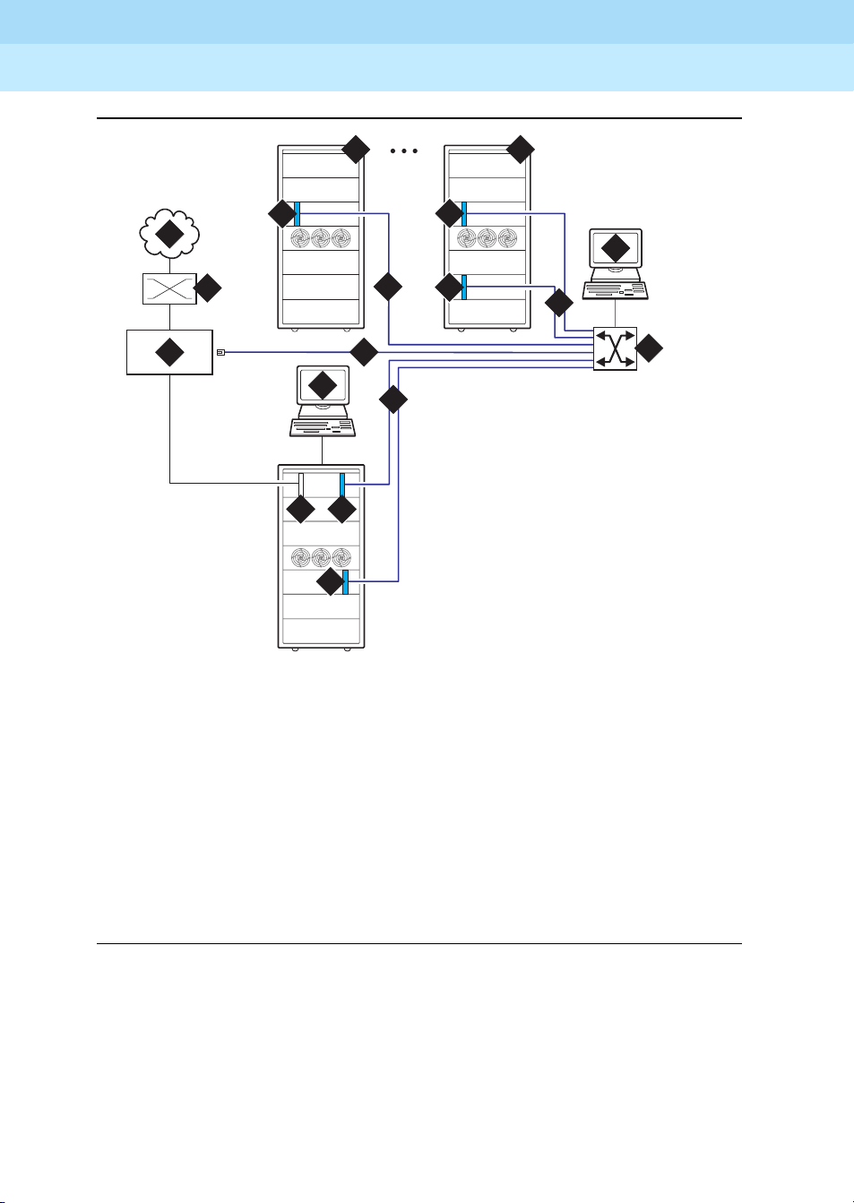
Review Configuration and Equipment
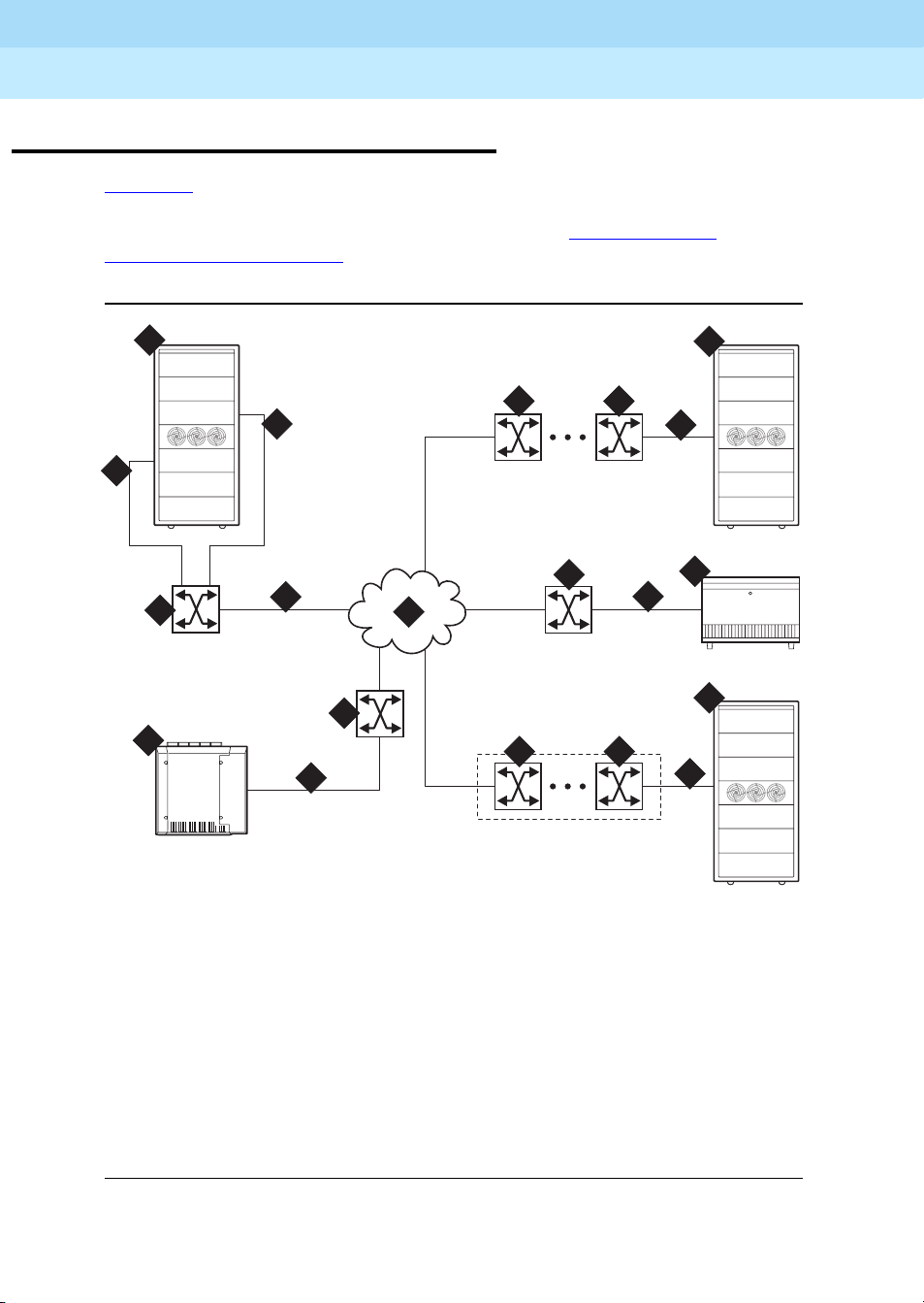
Figure 1-1 shows and example of the basic ATM connections for Release 8r and
Release 8csi system using ATM-PNC and ATM-CES. For more detailed
connection diagrams of the reliability options, refer to ‘‘DEFINITY ECS
configurations’’ on page 1-6.
Issue 1
April 2000
1-3Review Configuration and Equipment
1
2 2
6
7
2
2
9
8
2
7
3
2 2
cydaaccs LJK 111099
6
4
6
5
4
6
Figure Notes
1. DEFINITY ECS PPN-1 (r)
2. Lucent ATM switch
3. ATM network (the cloud)
4. DEFINITY ECS EPN in MCC
5. DEFINITY ECS EPN in SCC
6. ATM-PNC
7. ATM-CES
8. ATM-PNC and ATM-CES
9. DEFINITY ECS PPN-2 (csi)
Figure 1-1. Example of an ATM-PNC and ATM-CES configuration
Page 22

DEFINITY ECS Release 8.2 ATM Installation,
Upgrades, and Administration
Preparing for Installation and Upgrades
1
555-233-124
Required Hardware
Table 1-1 lists the required equipment for standard, high, critical reliability, and
ATM network duplication configurations.
Table 1-1. Minimum required equipment for Release 8 ATM-PNC configurations
Reliability level
Critical/ATM
Equipment
ATM switch 1 1 2
TN2305/TN2306 ATM interface
for each PN
T1 or E1 synchronization splitter
SC-connected fiber optic cable
Standard High
1
11
3
11 1
4
1 2 (PPN)
2
1 (each EPN)
Network Duplication
2
2
Issue 1
April 2000
1-4Review Configuration and Equipment
TN771 maintenance/test circuit
5
pack
1. TN2305 (multimode fiber); TN2306 (single-mode fiber) for Release 8 ATM-PNC.
2. High reliability requires 2 ATM-EI circuit packs in the PPN and 1 ATM-EI in each EPN.
3. The nu mber and uses of the synchronization splitter depend on the configuration and the source(s)
from which primary and secondary synchronization is derived. You may need 1 sync splitter per
ATM switch. DS1 synchronization requires either no sync splitter or up to a number twice the
number of sites.
4. Exis ting fiber optic cable may require an ST-to -SC adapter, depending on the interface at the AT M
switch. The
Fiber Pass-Through Kit).
5. For network duplication; required for systems supporting PRI, BRI, or ASAI.
TN2305/TN2306 circuit pack requ ires an SC connector (1 adapter is incl uded in the
1
To test the synchronization splitters, you need the following equipment:
■ Phoenix 1541C Test Set with accessory cord kit
■ Phoenix 5575A T1 Test Set with cord kit or equivalent
■ 700A DS1 CPE Loopback Jack
■ 103A block
■ 1541CC cable kit
1
(comcode 10798867)
1. See DEFINITY ECS Release 8 Maintenance for R8r, Chapter 6, DS1 Loopback Test for
more information.
Page 23

DEFINITY ECS Release 8.2 ATM Installation,
Upgrades, and Administration
Preparing for Installation and Upgrades
1
■ RJ45-to-Bantam test cable from the 1541CC cable kit
■ System capacities
555-233-124
Issue 1
April 2000
1-5Review Configuration and Equipment
Table 1-2
lists the maximum number of TN2305/TN2306 circuit packs allowed in
a DEFINITY ECS.
Table 1-2. Maximum number of ATM interface TN2305/TN2306 circuit packs
Maximum ATM circuit
Platform
packs allowed Description
r 176 2 x 44 port networks (CES) plus 2 in
eac h PN (PNC)
si, csi, c 6 CES only (no PNC)
Page 24
DEFINITY ECS Release 8.2 ATM Installation,
Upgrades, and Administration
Preparing for Installation and Upgrades
1
555-233-124
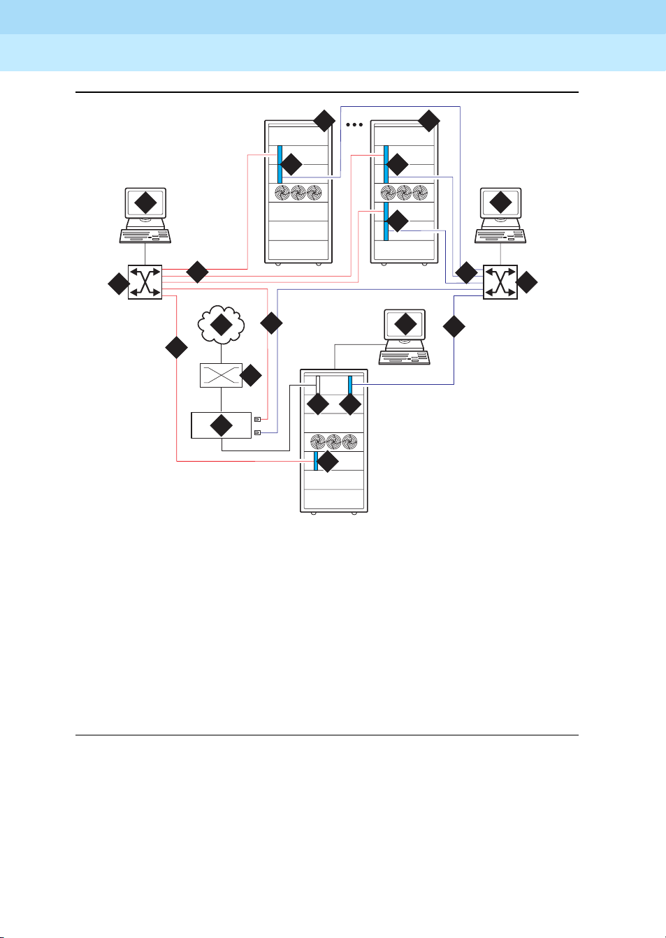
DEFINITY ECS configurations
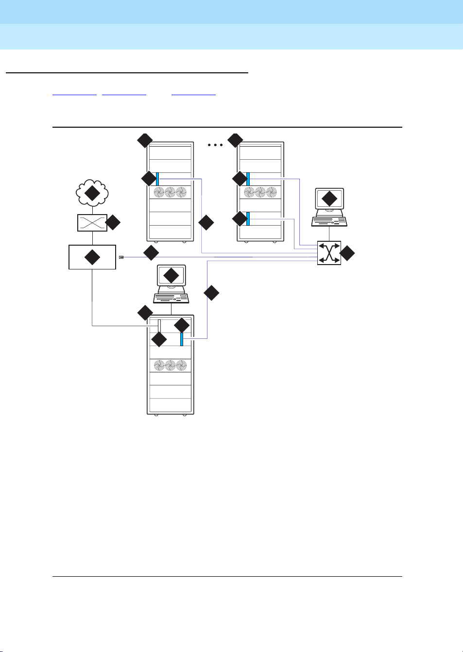
Figure 1-2, Figure 1-3, and Figure 1-4 show the ATM-PNC connections for
standard, high, and critical reliability, respectively.
Issue 1
April 2000
1-6Review Configuration and Equipment
10
12
5
9
5
8
10
11
5
1
2
3
7
6
13
5
4
cydaeps7 LJK 020100
Figure Notes
1. Public switched telephone network (PSTN)
2. Main d i stribution frame (MDF) or smart jack
3. Synchronization splitter.
4. DS1 circuit pack (TN464F)
5. TN2305/TN2306 circuit packs
6. DEFINITY ECS access terminal
7. Timing signal from synchronization splitter
through an H600-383 cable to Lucent ATM switch
8. Lucent A T M switch (more than one AT M
switch in an ATM-WAN configuration.)
9. ATM switch access terminal
10. Fiber optic cables from ATM
OC-3/STM-1 interfaces
11. DEFINITY ECS EPN
12. Split cabinet EPN
13. DEFINITY ECS PPN
Figure 1-2. ATM-PNC connections for standard reliability
Page 25
DEFINITY ECS Release 8.2 ATM Installation,
Upgrades, and Administration
Preparing for Installation and Upgrades
1
555-233-124
Issue 1
April 2000
1-7Review Configuration and Equipment
11 12
5
1
2
3
4
7
6
5
5
Figure Notes
1. Public switched telephone network (PSTN)
2. Main d i stribution frame (MDF) or smart jack
3. Synchronization splitter
4. DS1 circuit pack (TN464F)
5. TN2305/TN2306 circuit packs
6. DEFINITY ECS access terminal
7. Timing signal from synchronization splitter
through an H600-383 cable to Lucent ATM switch
5
8
8
cydaeph4 LJK 020100
5
8. Fiber optic cables to ATM OC-3/STM-1
9. Lucent A T M switch (more than one AT M
10. ATM switch access terminal
11. DEFINITY ECS EPN
12. Split-cabinet EPN
10
8
9
interfaces
switch in an ATM-WAN configuration.)
Figure 1-3. ATM-PNC connections for high reliability
Page 26
DEFINITY ECS Release 8.2 ATM Installation,
Upgrades, and Administration
Preparing for Installation and Upgrades
1
555-233-124
Issue 1
April 2000
1-8Review Configuration and Equipment
13
5
10
9
8
1
88
3
7
2
4
5
5
cydaepn3 LJK 020100
14
5
12
5
8
6
88
11
Figure Notes
1. Public switched telephone network (PSTN)
2. Main d i stribution frame (MDF) or smart jack
3. Synchronization splitter
4. DS1 circuit pack (TN464F)
5. TN2305/TN2306 circuit packs
6. DEFINITY ECS access terminal)
7. Timing signal from synchronization splitter
through an H600-383 cable to Lucent ATM switch
8. Fiber optic cables to ATM interfaces
9. Lucent ATM switch B
10. ATM switch access terminal B
11. Lucent ATM switch A
12. ATM switch access terminal A
13. DEFINITY ECS EPN
14. Split-cabinet EPN
Figure 1-4. ATM-PNC connections for critical reliability or ATM network
duplication
Page 27
DEFINITY ECS Release 8.2 ATM Installation,
Upgrades, and Administration
Preparing for Installation and Upgrades
1
555-233-124
Determine ATM Switch Suitability
To fully support DEFINITY ATM-PNC and provide nonblocking ATM access
between all port networks, ATM switches must support at least 400
point-to-multipoint switched virtual connection (SVC) roots or leaves per
OC-3/STM-1 interface. Because different switches have different limits—some
limit roots, some leaves, and some the total, we have developed the Meiners’
Algorithm to determine whether a switch can support a proposed set of port
networks in a proposed switch. This algorithm is available to Lucent engineers as
a calculator within a Microsoft Excel spreadsheet. You may access the MS Excel
file at http://info.dr.lucent.com/~meiners/atm.html
updates.
For best results, use the calculator for one ATM switch at a time. Use trial and
error to set the values in the user-defined values section until the feasibility
indicator reports
YES
NOTE:
Use of this spreadsheet is no substitute for thinking. Please apply basic
sanity checks to the outcome. ATM switches may have limitations that the
calculator does not consider.
PROBABLY
or
.
Issue 1
April 2000
1-9Determine ATM Switch Suitability
. Check periodically for
To use the calculator, type the network layout and resource limits for the ATM
switch you are using. Refer to the following caveats as you input your information:
1. Not all ATM switches have limits on all of the values. If a limit does not
apply, enter any very large number (1000000 is good).
2. Some ATM switches (for example, access concentrators) allow a limited
ability to configure the limits. Other switches have fixed limits. If you do not
know the limits, ask the ATM switch vendor.
3. If your ATM switch is handling non-DEFINITY traffic, enter the resource
limits after subtracting the resources used by the non-DEFINITY traffic.
4. If you are using an ATM switch with different limits on different modules or
ports (for example, Lucent Cajun M770):
a. compute the average limits per port to which a DEFINITY port
network is attached.
b. select the port with the most restrictive limitations.
c. enter the system limit as these limits times the number of DEFINITY
port networks attached to that ATM switch.
NOTE:
The more partitioned the limits are, the less accurate are the
results of the spreadsheet.
5. If you answer "yes" to transit traffic, the calculator may or may not be able
to determine feasibility. If it cannot, the feasibility displays as
UNKNOWN
.
Page 28

DEFINITY ECS Release 8.2 ATM Installation,
Upgrades, and Administration
Preparing for Installation and Upgrades
1
555-233-124
Figure 1-3 shows an example of a calculation.
Table 1-3. Sample calculation
Network Layout
Customer
Issue 1
April 2000
1-10Determine ATM Switch Suitability
SV
ATM switch
Total number of DEFINITY port networks:
Number of PNs directly attached directly to this ATM switch:
Is the DEFINITY PPN directly attached to this ATM switch
(yes/no)
Number of trunks on this ATM switch (inter-ATM-switch
connections)
Any transit traffic through this ATM switch (yes/no)
Aggregate peak phone calls rate per hour in all directly
connected PNs
Bidirectional aggregate trunk bandwidth in Mbps
Application bandwidth in kbps needed per port network
ATM Switch Resource Limits
(see "Limits" sheet for help)
Number of PP SVCs supported:
Number of PMP (roots) supported:
Number of PMP parties (leaves) supported:
Number of PMP endpoints (roots+leaves) supported:
Total number of SVCs (PP+PMP) supported
AC120
25
12
yes
1
no
10000
155.52
128
1000
6250
8334
1000000
1000000
Per-port SVC limit (normally based on VCI range)
Setups per second at <220 ms per setup
Feasibility
Bandwidth limited
PROBABLY
means that this application is okay under any reasonable loads.
1000000
1000000
PROBABLY
2032 calls
Check the constraint tests results to see what kind of loads might be a problem.
YES means that this application is okay under any load.
NO
means that this application is not reasonable. See the Constraint Tests results
to see what resource you are short of. See if you can increase this resource, or
decrease the number of port networks.
Page 29

DEFINITY ECS Release 8.2 ATM Installation,
Upgrades, and Administration
Preparing for Installation and Upgrades
1
555-233-124
Issue 1
April 2000
1-11Determine ATM Switch Suitability
UNKNOWN
means that special engineering is required for this application
because of the transit traffic. The special treatment is necessary because the
feasibility depends on the volume of the transit traffic. Making any of the changes
suggested for NO above might make it feasible regardless of the transit traffic.
Table 1-4. Constants
Timeslots per port network 500
Cache hit ratio 50%
EAL+PACL bandwidth 96
Table 1-5. Computed values
Number of nonlocal port networks 13
Effective number of port networks for PP 24
Effective number of por t networks for PMP 24
Number of available timeslots 10064
Per-port SVCs (PP+PMP) needed 572
PP SVCs perPN 3
Total PP SVCs 72
PP cells per second required over trunks 15158
Aggregate cells per second available over trunks 366792
Bandwidth-limited maximum phone calls over trunks 2032
Timeslot-limited maximum phone calls over trunks 3000
Constraint tests
If your calculations do not yield a
which you are short. These tests check 7 A T M switch resource limitations against
6 different application scenarios. A 1 in the Test Results (Table 1-7
passed test; a 0 indicates a failed test. To achieve a
must pass. To achieve a
pass.
YES
PROBABLY
, this section provides the resources of
) indicates a
YES
feasibility, all 42 tests
, only 21 tests (indicated in
bold
) must
Page 30

DEFINITY ECS Release 8.2 ATM Installation,
Upgrades, and Administration
Preparing for Installation and Upgrades
1
555-233-124
April 2000
Table 1-6. Application scenarios
Number of 2-party calls 2516 0 0 0 0 1258
Number of 3-party calls 0 1118 0 0 0 279
Number of 4-party calls 0 0 629 0 0 78
Number of 5- party calls 0 0 0 402 0 25
Number of 6-party calls 0 0 0 0 279 18
Tab le 1- 7 . Tes t r es ul t s
Issue 1
1-12Determine ATM Switch Suitability
Constraint 1: Timeslots 11
Constraint 2: PMP roots 11
Constraint 3: PP 11
Constraint 4: PMP leaves 11
Constraint 5: PMP endpoints 11
Constraint 6: Total SVCs 11
Constraint 7: Per-port SVCs 11
Constraint 8:Performance 11
Constraint 9:Trunk bandwidth 11
Final notes
The goal is to engineer the network so that in all reasonable applications, you
always run out of DEFINITY time slots before running out of ATM switch
resources. This is required to provide acceptable service to the customer.
These calculations factor in phone calls only. There is no specific
accommodation for the ATM SVC cache, or for special features such as music,
announcements, and group paging. The theory behind using 500 as the number
of timeslots in a port network rather than the real number (484) is to allow for a
normal amount of these special features. If you use multiple music on hold, group
paging, and so forth, you may need special engineering.
111
111
111
110
111
111
111
111
111
1
1
1
1
1
1
1
1
1
This calculator determines that an application is
handle reasonable activity mixes. The three columns in Table 1-7
PROBABLY
feasible if it can
that have bold
entries define what is meant by reasonable. These tests require that the switch
be able to handle a complete suite of 2-party calls, a complete suite of 3-party
calls, and a mixed suite that involves some calls of each type. For best results,
your application should pass all the constraint tests.
Any ATM switch that processes transit traffic (that is, connections that do not
either originate or terminate on any of the port networks directly attached to it)
may require special engineering. This is possible if the number of trunks on the
Page 31

DEFINITY ECS Release 8.2 ATM Installation,
Upgrades, and Administration
Preparing for Installation and Upgrades
1
555-233-124
ATM switch is more than one. If this is the case, the calculator first attempts to
determine if the application is feasible despite the transit traffic. If it is, it reports
the feasibility as
UNKNOWN
, requiring special engineering.
YES
PROBABLY
or
. If not, it reports the feasibility as
Known limits of commonly used ATM switches
Use the limits shown in Table 1-8 to do your own calculations. To make it easier
as you use the calculator, we suggest that you
1. Select and copy the values from the table in the spreadsheet.
2. Select the values on the sample calculation.
Issue 1
April 2000
1-13Determine ATM Switch Suitability
3. Select
Edit > Paste Special
with the transpose option to paste the values
into the calculator.
NOTE:
These limits are the best we could determine at one time. For each switch,
the example shown is generally the best you can do, assuming you bought
the maximum configuration and you administered it optimally for DEFINITY
(which are not necessarily the default settings). Consult the switch vendor
for confirmation of current limits.
Page 32

DEFINITY ECS Release 8.2 ATM Installation,
Upgrades, and Administration
Preparing for Installation and Upgrades
1
555-233-124
A limit shown as 1000000 means that this ATM switch has no independently
defined limit on this resource.
Table 1-8. Known limits of commonly used ATM switches
Issue 1
April 2000
1-14Schedule Installation or Upgrade
Number
Number
of PP
SVCs
Switch
Lucent PSAX1250
Release 5.0 1000000 1000000 1000000 1000 1000000 1000000 1000000
Release 5.1 1000000 1000000 1000000 4000 1000000 1000000 1000000
Release 6 (with
recommended
admin)
Lucent M770 r2
Dual Domain
Modules 1&8
Dual Domain
Modules 2-7&9-14
Single Domain 1000000 1024 1000000 1000000 1000000 1000000 1000000
Fore ASX1000
Release 6 (with
memory model 5)
supported
1000000 4096 1000000 1000000 1000000 1000000 1000000
1000000 2048 1000000 1000000 1000000 1000000 1000000
Number
of PMP
(roots)
supported
1000 6250 8334 1000000 1000000 1000000 1000000
2048 2048 16384 1000000 1000000 1000000 1000000
of PMP
parties
(leaves)
supported
Number
of PMP
endpoints
(roots +
leaves)
supported
To ta l
number
of SVCs
(PP+PMP)
supported
Per-port
SVC limit
(normally
based on
VCI
range)
Setups/s
at
<220 s/set
up
Schedule Installation or Upgrade
Schedule the installation or upgrade with the Lucent Technologies Technical
Support Organization (TSO) and NetCare® Professional Services (NPS). See
‘‘Where To Call for Technical Support’’ on page -xi
.
Page 33

DEFINITY ECS Release 8.2 ATM Installation,
Upgrades, and Administration
Installing a DEFINITY ECS ATM-CES
2
555-233-124
Installing a DEFINITY ECS
AT M - C ES
This chapter describes the procedures for installing a new DEFINITY ECS
Release 8 AT M-CES The procedure is simple in that you install the DEFINIT Y ECS
then install the ATM switch and the TN2305/TN2306 interface circuit packs.
Making it an A T M-CE S is done administratively (refer to
ATM-PNC and ATM-CES’’).
Issue 1
April 2000
2-1Equipment Installation
2
Chapter 5, ‘‘Administering
NOTE:
ATM-CES works only with TN2305/TN2306 ATM interface circuit packs.
Equipment Installation
To prepare for a new DEFINIT Y ECS ATM-CES installation, you need to install the
DEFINITY ECS first. For instructions on installing DEFINITY ECS, refer to the
following installation books:
■ DEFINITY Enterprise Communications Server Release 8 Installation and
Test for Multicarrier Cabinets
■ DEFINITY Enterprise Communications Server Release 8 Installation and
Test for Single-Carrier Cabinets
■ DEFINITY Enterprise Communications Server Release 8 Installation,
Upgrades, and Additions for Compact Modular Cabinets
Review the reliability configurations for DEFINITY Release 8 ATM (refer to
1-2 through
The slot restrictions for a CES configuration are similar to ISDN-P RI circuit packs.
In PPNs and EPNs, ATM interface circuit packs can occupy any available slot in
a port carrier.
Figure 1-4
Figure
).
Page 34

DEFINITY ECS Release 8.2 ATM Installation,
Upgrades, and Administration
Installing a DEFINITY ECS ATM-CES
2
555-233-124
Follow the steps in Table 2-1 to ensure that
■ the applicable equipment is installed correctly.
■ the customer’s configuration is properly recorded (use worksheet in
Appendix A, ‘‘Baselining the Customer’s Configuration’’
Table 2-1. General installation process
√ Step Action Description
1. Install DEFINITY ECS Refer to the appropriate installation book for your platform
See
‘‘DEFINITY ECS configurations’’ on page 1-6 for
connection schematics.
2. Install ATM switch(es)
or access
concentrators
Refer to your ATM switch’s quick reference guide.
Issue 1
April 2000
2-2Equipment Installation
).
3. Install ATM interface
circuit pack
4. Route the fiber optic
cables between the
ATM switch and the
DEFINITY PPN and
EPNs.
5. Connect the fiber
optic cables
6. Connect the fiber
optic cables to the
ATM interfac e cir cui t
packs
Insert the TN2305/TN2306 circuit pack(s) into the
appropriate slot(s).
Follow the fiber pass-through procedure in the appropriate
DEFINITY ECS installation book
!
WARNING:
.
Be sure that the fiber optic cable is secured so that
the door of the DEFINITY ECS sw itch does n ot pinc h
or bend the cable.
For csi platfo rm, see Figure 2-1 for a diagram of the NAA7
board that routes fiber optic cabling from the back of the
switch to the front.
Connect the fiber optic cables to the ATM switch.
NOTE:
If the installation uses the customer’s existing fiber,
you may need an ST-to-SC adapter (1 included in
Fiber Pass-Through Kit).
Connect fiber optic cable to the SC connector on the
faceplate of each TN2305/TN2306 circuit pack in the
DEFINITY PPN and EPN.
■ Th e TN2305/TN23 06 circuit pac k interface requi res SC
connectors (see Note in Step 5).
■ Do not reuse existing fiber cabling with ST connectors
at both the DEFINITY ECS and the ATM switch. This
requires an ST-to-SC adapter at both ends. It is better
to order the cable w i th th e SC c onn ec tors at b oth end s .
Continued on next page
Page 35

DEFINITY ECS Release 8.2 ATM Installation,
Upgrades, and Administration
Installing a DEFINITY ECS ATM-CES
2
555-233-124
Table 2-1. General installation process
√ Step Action Description
7. Record configuration Record DEFINITY ECS switch-to-ATM port (port locations
for each ATM circuit pack) in
‘‘Baselining the Customer’s Configuration’’.
Issue 1
April 2000
2-3NAA7 Board (csi/c models only)
Table A-1 in Appendix A,
8. Record fiber
connections
Record the fiber optic cable runs on the lightw a ve interface
(LIU) diagram (
the Customer’s Configuration’’).
NAA7 Board (csi/c models only)
The NAA7 board routes fiber optic connections from the rear of the cabinet
through the front faceplate as shown in Figure 2-1
go through the faceplate connect to the faceplate connectors on the
TN2305/TN2306 ATM circuit pack.
A
B
A
B
Figure A-1 in Appendix A, ‘‘Baselining
Continued on next page
. The SC fiber connectors that
ckdanaa1 LJK 021199
Figure 2-1. NAA7 board (csi and c models only)
A
B
B
A
B
A
Page 36

DEFINITY ECS Release 8.2 ATM Installation,
Upgrades, and Administration
Installing a DEFINITY ECS ATM-CES
2
555-233-124
Issue 1
April 2000
2-4NAA7 Board (csi/c models only)
Page 37

DEFINITY ECS Release 8.2 ATM Installation,
Upgrades, and Administration
Installing a DEFINITY ECS ATM-PNC
3
555-233-124
Installing a DEFINITY ECS
AT M - P N C
This chapter describes the procedures for installing a new DEFINITY ECS
Release 8 ATM system. The process includes
Issue 1
April 2000
3-1Equipment Installation
3
■ Equipment Installation
■ Synchronization Installation and Testing
■ ATM Network Duplication
Equipment Installation
If the A T M switch and interface circuit packs are already installed, then the actual
upgrade to ATM-PNC is done administratively in
ATM-PNC and ATM-CES’’.
To prepare for a new DEFINITY ECS ATM installation refer to the following books:
■ DEFINITY Enterprise Communications Server Release 8 Installation and
Test for Multicarrier Cabinets
■ DEFINITY Enterprise Communications Server Release 8 Installation and
Test for Single-Carrier Cabinets
Review the reliability configurations for DEFINITY Release 8 ATM (refer to
1-2 through Figure 1-4) and determine the synchronization sources (DS1, E1, or
ATM network).
Chapter 5, ‘‘Administering
Figure
Page 38

DEFINITY ECS Release 8.2 ATM Installation,
Upgrades, and Administration
Installing a DEFINITY ECS ATM-PNC
3
555-233-124
Slot restrictions for an ATM interface circuit packs are similar to expansion
interface circuit packs:
■ PP N: ATM interface circuit packs used for A T M-P NC must occupy the slots
labeled EXPANSION INTERFACE.
■ EPNs: ATM interface circuit packs used for ATM-PNC can occupy slot 1
(and 2 if duplicated) on carrier A, and slot 2 (and 3 if duplicated) on carrier
B
Issue 1
April 2000
3-2Equipment Installation
Follow the steps in Table 3-1
■ the applicable equipment is installed correctly.
■ the customer’s configuration is properly recorded (use worksheet in
to ensure that
Appendix A, ‘‘Baselining the Customer’s Configuration’’
Table 3-1. General installation process
√ Step Action Description
1. Install DEFINITY ECS
switch
2. Install ATM switch(es)
or access
concentrators
3. Check the distances
from the ATM switch
to the DS1 timing
source
4. Install ATM interface
circuit pack
5. Route the fiber optic
cables between the
ATM switch and the
DEFINITY PPN and
EPNs.
Refer to the app ropriate installation book
See ‘‘DEFINITY ECS configurations’’ on page 1-6
connection schematics.
Refer to your ATM switch’s quick reference guide.
Use the information in Table 3-3
maximum cable run lengths for the configuration for more
information.
Insert the TN2305/TN2306 circuit pack(s) into the
appropriate slot(s).
Follo w the fi ber pass-through procedure in the appropriate
installation book.
!
WARNING:
Be sure that the fiber optic cable is secured so that
the door of the DEF I NITY ECS switch does not pinch
or bend the cable.
).
for
to determine the
6. Connect the fiber
optic cables
Connect the fiber optic cables to the ATM switch.
NOTE:
If the installation uses the customer’s existing fiber,
you may need an ST-to-SC adapter (1 included in
Fiber Pass-Through Kit).
Continued on next page
Page 39

DEFINITY ECS Release 8.2 ATM Installation,
Upgrades, and Administration
Installing a DEFINITY ECS ATM-PNC
3
Table 3-1. General installation process
√ Step Action Description
555-233-124
Issue 1
April 2000
3-3Synchronization Installation and Testing
7. Connect the fiber
optic cables to the
ATM interface circuit
packs
8. Record configuration Record DEFINITY ECS switch-to-ATM port (port locations
Connect fiber optic cable to the SC connector on the
faceplate of each TN2305/TN2306 circuit pack in the
DEFINITY PPN and EPN.
■ T he TN2305/TN2306 circuit pack interface requires S C
connectors (see Note in Step 5).
■ D o not reuse existing fiber cabling with ST connectors
at both the DEFINITY switch and the ATM switch. This
requires an ST-to-SC adapter at both ends. It is better
to order the cable with the SC connectors at both
ends.
for each ATM circuit pack) in Table A-1
‘‘Baselining the Customer’s Configuration’’).
(in Appendix A,
NOTE:
Read the MAC addresses from the ATM switch (refer
to your ATM switch’s quick reference guide) and
.
) in Appendix A,
9. Record fiber
connections
10. Install and test
synchronization
splitter, if required.
record them in Table A-1
Record the fiber optic cable runs on the lig htwave
interface (LIU) diagram (Figure A-1
‘‘Baselining the Customer’s Configuration’’.
Follow the procedures for installing and testing the
synchronization splitter and the T1 or E1 timing source in
‘‘Synchronization Installation and Testing’’ on page 3-3
.
Synchronization Installation and Te st in g
A DEF INIT Y ATM-PNC requires network synchronization for DS1 circuit packs not
to slip relative to the LEC/IXC switches. The ATM switch serves as the sync
reference source for the DEFINITY. The ATM switch, in turn, derives primary and
secondary sync. To accomplish this, the most common option is to use
synchronization expanders (splitters).
Continued on next page
Page 40

DEFINITY ECS Release 8.2 ATM Installation,
Upgrades, and Administration
Installing a DEFINITY ECS ATM-PNC
3
555-233-124
Connections without synchronization splitters
In some configurations the ATM switches are traced to network clocks through
their SONET/SDH interfaces, not requiring any synchronization splitters.
However, the ATM switch could require a single splitter if only one of the sync
sources is derived from the network.
The ATM switches may obtain their network synchronization as follows:
■ The ATM switch gets its network timing reference from its
SONET/SDH/SDIT interface to that network.
■ Or if the customer wants to use a DS1 source for network synchronization
that also happens to be a DEFINITY ECS switch trunk, then one sync
splitter is necessary to send a copy of that DS1 signal to the ATM switch.
The DS1 circuit pack is only an indirect timing reference for the DEFINITY
ECS switch.
Connections needing synchronization splitters
Issue 1
April 2000
3-4Synchronization Installation and Testing
If the ATM network does not provide a synchronization expander (splitter), then
the ATM configurations may require one that takes a DS1 T1 or E1 signal and
redirects it to the
■ ATM switch(es), depending on configuration and duplication
■ DEFINITY ECS through the DS1 circuit pack
This creates a single synchronization source.
Check the customer’s configuration carefully so that you can
■ Connect the hardware correctly during installation
■ Properly administer the synchronization plan later (
Chapter 5,
‘‘Administering ATM-PNC and ATM-CES’’)
This section covers the synchronization installation and test process.
■ Splitter descriptions—Describes the splitter’s inputs and outputs
■ Synchronization splitter connections—Connection diagrams for timing
connections through a DSU/CSU (
■ Verify the DS1 service—Checks for presence of the DS1 T1 or E1 timing
Figure 3-6
) and an ICSU (
Figure 3-7
)
source and the general health of the DS1 circuit pack.
■ Installing and testing the splitter provides the following information
Splitter port tests (401A/401A only)
—
Installing a 400A T1 splitter
—
Installing 401A, 402A, or 403A splitters
—
Page 41

DEFINITY ECS Release 8.2 ATM Installation,
Upgrades, and Administration
Installing a DEFINITY ECS ATM-PNC
3
555-233-124
Installing and testing the synchronization splitter involves interrupting the DS1
signal provided by the service provider. Even though the DS1 circuit pack should
be down less than 5 minutes, before removing a working T1/E1 span, contact the
service provider. Failure to notify the T1/E1 service provider may result in:
— The service provider looping the T1/E1 span back to the
subscriber.
— A span alarm being detected at the central office and the span
being taken out of service, sending an AIS (blue Alarm) to the
DEFINITY ECS. The synchronization signal is necessary for testing
equipment and connections.
Splitter descriptions
Table 3-2 describes the 4 splitter models and their capabilities. The drawings
show the splitters and their connection points. Figure 3-5
the 2 jumper sets and their connections for 401A, 402A, and 403A sync splitters.
Table 3-2. Synchronization splitter models and attributes
Issue 1
April 2000
3-5Synchronization Installation and Testing
shows a schematic of
Model T1/E1 Impedance Comcode Drawing Description/Application
400A T1 100 Ω 108217795 Figure 3-1 No ICSU capability
401A T1 100 Ω 108508078 Figure 3-2
402A E1 120 Ω 108508094 Figure 3-3
403A E1 75 Ω 108508102 Figure 3-4
Limited ICSU capability
Continued on next page
Page 42

DEFINITY ECS Release 8.2 ATM Installation,
Upgrades, and Administration
Installing a DEFINITY ECS ATM-PNC
3
555-233-124
Issue 1
April 2000
3-6Synchronization Installation and Testing
3
4
J1
J2
1
crda400a LJK 071698
2
Figure Notes:
1. From network interface
2. Amphenol connection to
3. Timing outp ut port (J1) to the ATM switch
4. Timing outp ut port (J2) to the ATM switch
DEFINITY ECS
1. Ports J1 and J2 provide identical DS1 timing source signals to the ATM switches.
The ATM switch can use two separate DS1 timing signals (one at a time from two
separate spans).
1
1
Figure 3-1. 400A synchronization splitter
Page 43

DEFINITY ECS Release 8.2 ATM Installation,
Upgrades, and Administration
Installing a DEFINITY ECS ATM-PNC
3
555-233-124
5
1
3
2
NETWORK
lo
o
n
h
c
Te
t
n
e
c
u
L
401A
108508078
H
O
0
0
1
P
S
C
N
Y
S
TO DEFINITY
ie
g
M
L
ALARM
s
T
T
IT
1
R
E
Issue 1
April 2000
3-7Synchronization Installation and Testing
crda401a KLC 020300
TO ATM SWITCH
4
5
Figure Notes:
1. Amphenol connector to
DEFINITY ECS
2. Network timing connection
1. Ports J1 and J2 provide identical DS1 timing source signals to the ATM switches.
The ATM switch can use two separate DS1 timing signals (one at a time from two
separate spans).
3. Timing alarm lead connection
4. Timing output ports (RJ45) to ATM switch
1
5. Jumpers and capacit ors (inside case). See
Figure 3-5 for settings.
Figure 3-2. 401A synchronization splitter
Page 44

DEFINITY ECS Release 8.2 ATM Installation,
Upgrades, and Administration
Installing a DEFINITY ECS ATM-PNC
3
555-233-124
5
1
3
2
NETWORK
lo
o
n
h
c
Te
t
n
e
c
u
L
402A
108508094
H
O
0
2
1
P
S
C
N
Y
S
TO DEFINITY
ie
g
M
L
ALARM
s
E
T
IT
1
R
E
Issue 1
April 2000
3-8Synchronization Installation and Testing
crda402a KLC 020300
TO ATM SWITCH
4
5
Figure Notes:
1. Amphenol connector to
DEFINITY ECS
2. Network timing connection
1. Ports J1 and J2 provide identical DS1 timing source signals to the ATM switches.
The ATM switch can use two separate DS1 timing signals (one at a time from two
separate spans).
3. Timing alarm lead connection
4. Timing output ports (RJ45) to ATM switch
1
5. Jumpers and capacit ors (inside case). See
Figure 3-5 for settings.
Figure 3-3. 402A synchronization splitter
Page 45

DEFINITY ECS Release 8.2 ATM Installation,
Upgrades, and Administration
Installing a DEFINITY ECS ATM-PNC
3
555-233-124
Issue 1
April 2000
3-9Synchronization Installation and Testing
5
4
X
T
K
R
X
R
O
W
T
E
N
6
1
Figure Notes:
1. Amphenol connector to DEFINITY
ECS
2. Synchronization source (timing
output ports) to ATM switch
3. Synchronization source (timing
output ports) to ATM switch
1
1
Lucent Technologies
403A
108508102
75 OHM E1
SYNC SPLITTER
TO DEFINITY
C
IT
W
S
M
TO AT
3
2
4. Network receive connection, BNC
connector
5. Network transmit connection, BNC
connector
6. Jumpers and capacitors (inside case).
See Figure 3-5
H
6
crda403a KLC 020300
for settings.
1. These are identical DS1 timing source signals to the ATM switches. The ATM switch
can use two separate DS1 timing signals (one at a time from two separate spans).
Figure 3-4. 403A synchronization splitter
Page 46

DEFINITY ECS Release 8.2 ATM Installation,
Upgrades, and Administration
Installing a DEFINITY ECS ATM-PNC
3
555-233-124
Issue 1
April 2000
3-10Synchronization Installation and Testing
RX
TX
4
5
6
3
4
2
TX
1
NETWORK
3
2
ALARM
8
7
402A
108508094
120 OHM E1
1
5
5
6
3
4
2
TX
1
SYNC SPLITTER
TO DEFINITY
TO ATM SWITCH
6
Figure Notes:
1. Amphenol connection to DEFINITY
ECS switch
2. Row of capacitors
3. Jumpers for incoming network
connections
4. Incoming network transmit and
receive connections
5. Jumper 1-2 = true ground
Jumper 5-6 = shield ground ed
Jumper 3 = TX cable ground
Jumper 4 = RX cable ground
Default connections = 1-2, 3-5
6. True ground
7. Cable shield grounded
8. Jumper 1-2 = true ground
Jumper 5-6 = shield ground ed
Jumper 3 = ATM switch A TX cable ground
Jumper 4 = ATM switch B TX cable ground
Default connections = 3-5, 4-6
9. Output jumpers
10. Timing output to ATM switch A
11. Timing output to ATM switch B
Figure 3-5. Jumper settings (401A/402A/403A)
jpda40xa KLC 020300
Page 47

DEFINITY ECS Release 8.2 ATM Installation,
Upgrades, and Administration
Installing a DEFINITY ECS ATM-PNC
3
555-233-124
Synchronization splitter connections
The splitter connects to a timing source. Figure 3-6 shows the synchronization
connections through a DSU/CSU (400A), and Figur e 3-7
synchronization connections through an ICSU (400A). Figure 3-8
synchronization connections directly to the timing source (401A, 402A, 403A).
Issue 1
April 2000
3-11Synchronization Installation and Testing
shows the
shows the
1
2
8 9
7
6
5
4
3
cydaatm2 LJK 020100
Figure Notes:
1. Public Switched Telephone
Network (PSTN)
2. Main distr ibution frame (MDF) or
smart jack.
3. Channel service unit (CSU)
4. H600-307-GR2 cab le
5. 400A T1 (100 Ω) splitter connects
to the DEFINITY ECS
6. H600-383 quad cable from sync splitter to ATM
switch A
7. H600-383 q uad cable from sync splitter to ATM
switch B (critical reliability/ATM network
duplication)
8. Lucent ATM switch A
9. Luc ent ATM switch B (critical reliability/ATM
network duplication)
Figure 3-6. Synchronization connections through an external DSU/CSU
(400A
)
Page 48

DEFINITY ECS Release 8.2 ATM Installation,
Upgrades, and Administration
Installing a DEFINITY ECS ATM-PNC
3
555-233-124
Use the in fo rmat i on in Table 3-3 to determine the maximum cable run lengths for
the configuration.
7 8
Issue 1
April 2000
3-12Synchronization Installation and Testing
6
5
1
9
3
2
4
cydaatm1 LJK 020100
Figure Notes:
1. Public Switched Telephone
Network (PSTN)
2. Main Distribution Frame (MDF) or
smart jack
3. H600-383 quad cable
4. 400A T1 (100 Ω) splitter connected
to DEFINITY ECS
5. H600-383 quad cable from sync splitter to ATM
switch A
6. H600-383 q uad cable from sync splitter to
duplicated ATM switch B (critical reliability)
7. Lucent ATM switch A
8. Lucent ATM switch B (critical reliability
network duplication)
9. ICSU
Figure 3-7. Synchronization connections through an ICSU (400A)
/ATM
Page 49

DEFINITY ECS Release 8.2 ATM Installation,
Upgrades, and Administration
Installing a DEFINITY ECS ATM-PNC
3
555-233-124
1
2
Issue 1
April 2000
3-13Synchronization Installation and Testing
3
4
7
6
5
cydaatm3 KLC 020200
8
Figure Notes:
1. Public switched telephone network
(PSTN)
2. Main d i stribution frame (MDF) or
smart jack
3. H600-383 quad cable
4. 401A T1 (100 Ω) splitter,
402A E1 (120 Ω) splitter, or
403A E1 (75 Ω) splitter connected
to DEFINITY ECS
5. H600-383 q uad cable from sync splitter to ATM
switch A
6. H600-383 q uad cable from sync splitter to
duplicated ATM switch B (critical reliability
network duplication)
7. Lucent ATM switch A
8. Lucent ATM switch B (critical reliability
network duplication)
Figure 3-8. Synchronization connections directly to timing source
(401A/402A/403A)
/ATM
/ATM
Page 50

DEFINITY ECS Release 8.2 ATM Installation,
Upgrades, and Administration
Installing a DEFINITY ECS ATM-PNC
3
555-233-124
Use the in fo rmat i on in Table 3-3 to determine the maximum cable run lengths for
the configuration.
Table 3-3. Maximum cable lengths
Issue 1
April 2000
3-14Synchronization Installation and Testing
Splitter Used in Cable
400A
T1
100 Ω
401A
T1
100 Ω
402A
E1
120 Ω
403A
E1
North America
(USA and Canada)
North America
(USA and Canada)
See Table 3-4
See Table 3-4
H600-383
shielded
twisted pair
H600-383
shielded
twisted pair
120-Ω
shielded
twisted pair
75-Ω
coaxial
1
1
Maximum distance from
splitter to ATM switch
250 feet
76 meters
1310 feet
2
393 meters
1000 feet
2
305 meters
1000 feet
2
305 meters
75 Ω
Continued on next page
1. Must have RJ45 connectors on each end.
2. The loss allowed in the cable is 6 dB. Typical cables have losses of 0.6 dB/100 ft;
hence, 1000 feet may be considered a typical distance. Distance varies if cables with
different losses are used.
Page 51

DEFINITY ECS Release 8.2 ATM Installation,
Upgrades, and Administration
Installing a DEFINITY ECS ATM-PNC
3
555-233-124
Table 3-4 lists the splitter model(s) applicable to specific countries.
Table 3-4. Country-specific splitter applications
Country
Argentina Y
Australia Y
Austria Y Y
Bahrain Y Y
Belgium Y Y
Brazil Y
Canada Y
China Y
Columbia Y
400A/401A
T1
100 Ω
Splitter model
402A
E1
120 Ω
Issue 1
April 2000
3-15Synchronization Installation and Testing
403A
E1
75 Ω
Denmark Y Y
Egypt Y Y
Finland Y Y
France Y Y
Germany Y Y
Hong Kong Y
India Y Y
Indonesia Y Y
Ireland Y Y
Italy Y Y
1
Japan
Korea Y Y
Luxembourg Y Y
Malaysia Y Y
Mexico Y
Netherlands Y Y
New Zealand Y Y
Norway Y Y
Continued on next page
Page 52

DEFINITY ECS Release 8.2 ATM Installation,
Upgrades, and Administration
Installing a DEFINITY ECS ATM-PNC
3
Table 3-4. Country-specific splitter applications —
Continued
Country
Philippines Y Y
Poland Y Y
Portugal Y Y
Russia Y Y
Saudi Arabia Y Y
Singapore Y
Sout h Afri ca Y Y
Spain Y Y
Sri Lanka Y Y
Sweden Y Y
555-233-124
400A/401A
T1
100 Ω
Splitter model
402A
E1
120 Ω
Issue 1
April 2000
3-16Synchronization Installation and Testing
403A
E1
75 Ω
Switzerland Y Y
Taiwan Y Y
Ukraine Y Y
UAE Y Y
UK Y Y
USA Y
Uzbekistan Y Y
Vietnam Y Y
Continued on next page
1. Japan uses both 75-Ω and 120-Ω T1; 402A and 403A sync
splitters will also work with T1s.
Page 53

DEFINITY ECS Release 8.2 ATM Installation,
Upgrades, and Administration
Installing a DEFINITY ECS ATM-PNC
3
555-233-124
Verify the DS1 service
To verify the DS1 service, use the procedure in Table 3-5. Have the ATM switch
installer verify the synchronization source.
Table 3-5. T1 or E1 service verification procedure
Step Action Command Description
√
1. Check timing
signal
2. Test the DS1
circuit pack
3. Run error report list
4. Identify active
synchronization
source
test board
UUCSS
measurements
UUCSS
ds1
summary
status
synchronization
Issue 1
April 2000
3-17Synchronization Installation and Testing
Check that the GREEN STATUS 3 LED on the
designated DS1 circuit pack is on steady.
Test the desig nated DS1 board.
If any one of Test 138 through 145 fails, follow the
repair procedures listed in DEF INIT Y E CS Maintenance
for R8r.
Verify that the report is free of errors.
See
Table 3-6 to help interpret the report.
V erify that the designated DS1 circuit pack is the active
sync source.
Note
: The DS1circuit pack is not the sync source; it
simply shows where the sync splitter is connec ted.
Continued on next page
Page 54

DEFINITY ECS Release 8.2 ATM Installation,
Upgrades, and Administration
Installing a DEFINITY ECS ATM-PNC
3
555-233-124
Table 3-6. Interpretation of the list measurements report
Displayed
Field Function Indication
Issue 1
April 2000
3-18Synchronization Installation and Testing
Test:
cpe-loopbac
k-jack
Synchronize
d
Bit Error
Count
3-in-24 stress
test patter n
= Y
= N
Cumulative
detected
errors
The loopback jack test is active
The DS1 circuit pack is synchronized to the looped
3-in-24 pattern and is counting the bit errors detected
in the pattern until the test is ended.
Retry the test:
1. Stop the test (
test ds1-loop
cpe-loopback-jack-test
2. Restart the test (
test ds1-loop
cpe-loopback-jack-test-begin
UUCSS
).
end
UUCSS
)
3. Repeat Steps 1 and 2 a maximum of 5 times, as
necessary.
If the circuit pack never synchronizes, it is possibly
due to intermittent connections or a broken wire in a
receive or transmit wire pair.
0 indicates that there are no wiring problems.
A count that sits at 65535 or continues to increment
by several hundred to several thousand errors with
each subsequent
list measurements
command
indicates
■ Intermittent or corroded connections
■ Severe crosstalk
■ Impedance imbalances between the two
conductors of the receive or the transmit pairs.
1. Replace wiring, if necessary.
2. Note whether the Extended Super Frame (ESF)
error and performance counters summaries
(errored seconds, bursty errored seconds, and so
forth) also increment. Although these counters are
not used with the loopback jack test, they do
increment as errors occur.
Continued on next page
Page 55

DEFINITY ECS Release 8.2 ATM Installation,
Upgrades, and Administration
Installing a DEFINITY ECS ATM-PNC
3
555-233-124
Installing and testing the splitter
The splitter must be installed and tested before the upgrade and cutover. The
purpose of testing the splitter is to
■ Prove that there is enough signal level for the cable length to the ATM
switch:
— up to 130 ft. (39.65 m) for 400A
— within the standard 6 dB allowable loss for 401A, 402A, and 403A
Table 3-3
(see
■ Ensure that the DS1 circuit pack functions properly while receiving the
DS1 signal level output from the splitter (Ports J1 and J2 unterminated).
)
Issue 1
April 2000
3-19Synchronization Installation and Testing
Table 3-7
shows the configurations of the test cable and ports on the sync
splitter.
Table 3-7. Cable and port configurations for splitter tests
To test Description
Port J1 Insert an opening plug into port J2
Port J2 Insert an opening plug into port J1
Maximum output of the splitter
to the DS1 circuit pack
Insert an opening plug into both ports J1 and J2
Continued on next page
Splitter port tests (401A/401A only)
NOTE:
The standard RJ45-to-Bantam test cable does not work with the 403A.
To test the splitter ports J1 or J2, use the procedures in
to Bantam Test cable from the 1541CC cable kit.
Table 3-8
, using the RJ45
Page 56

DEFINITY ECS Release 8.2 ATM Installation,
Upgrades, and Administration
Installing a DEFINITY ECS ATM-PNC
3
Table 3-8. Testing the splitter ports
√ Step Action Command Description
1. Terminate one
or more ports
2. Connect to
DS1 circuit
pack
3. Test
DS1circuit
pack
555-233-124
test board
UUCSS
Plug the RJ45 (modular) end of the DS1 tes t cable
into the jack (J1 or J2) you wish to test on the
splitter.
Plug the Bantam Plug end (plug with the b lack
band) of the DS1 test cable into the Equipment-In
(EI) jack on the DS1 circuit pack faceplate.
Wait 30 seconds, then test the circuit pack.
If any tests fail, wait 5 minutes and test the DS1
circuit pack again.
Issue 1
April 2000
3-20Synchronization Installation and Testing
4. Replace
splitter if
necessary
5. Escalate if
necessary
If any test still fails, replace the splitter and retest.
If the test still fails, escalate to Tier 3.
Continued on next page
Installing a 400A T1 splitter
NOTE:
Make sure you are connected to the network before connecting to the
DEFINITY ECS.
Once the sync splitter passes the DS1 span tests, it can be installed and tested
in place. The 400A sync splitter can be either
■ Connected through an ICSU
■ Connected through a DSU/CSU.
NOTE:
If using a TN464F /TN767E v18 or earlier, you must reseat the circuit pack
each time the splitter is plugged on.
Page 57

DEFINITY ECS Release 8.2 ATM Installation,
Upgrades, and Administration
Installing a DEFINITY ECS ATM-PNC
3
555-233-124
Issue 1
April 2000
3-21Synchronization Installation and Testing
Connected through an ICSU.
Use the procedures in Table 3-9
splitter between an ICSU and a DS1 circuit pack.
Table 3-9. Installing the splitter through an ICSU
Step Action Command Description
√
1. Disable
synchronization
switch
2. Busyout DS1
circuit pack
3. Remove cable
from DS1 circuit
pack
4. Remove ICSU Remove the ICSU from the designated DS1 circuit pack’s
5. Attach splitter Plug the splitter into the same c onnector just vacated by
6. Attach ICSU Plug the ICSU into the connector on the splitter.
7. Reconnect
cable
8. Check
connections
9. Secure splitter Secure the splitter to the carrier using the 4C retainer from
10. Secure ICSU Secure the ICSU to the splitter with a long cable tie.
disable
synchronization
-switch
busyout board
UUCSS
Prevent the system from switching synchronization
sources.
Busyout the designated DS1circuit pack.
Remove the existing H600-307 cable from the backplane
slot corresponding to the designated DS1 circuit pack.
amphenol connector.
Re-use the existing cable attached to the ICSU.
the ICSU.
Connect the H600-307 cable to the amphenol connector
on the ICSU.
Check that all Amphenol connections are good.
the ICSU.
to install the
11. Terminate the
splitter ports J1
and J2
12. Check DS1
Status 3 LED
13. Test the DS1
circuit pack
14. Clear the error
events counters
test board
UUCSS
clear
measurements
ds1
esf-error-events
UUCSS
Insert a modular RJ45 plug in both ports J1 and J2. Do not
connect port J1 to port J2, but leave the other end of both
cords free. The modular RJ45 plug acts as an opening
plug and removes the 100-Ω termination from port J1 and
J2 on the splitter.
After about 20 seconds the LEDs on the DS1 circuit pack
should go out, leaving only the GREEN STATUS 3 LED on.
Test the circuit pack.
If any one of Tests 138 - 145 fails, follow the repair
procedures listed in DEFINITY ECS Maintenance for R8r
Clear the error events counter.
Continued on next page
Page 58

DEFINITY ECS Release 8.2 ATM Installation,
Upgrades, and Administration
Installing a DEFINITY ECS ATM-PNC
3
555-233-124
Table 3-9. Installing the splitter through an ICSU — Continued
Step Action Command Description
√
15. Run report list
measurements
ds1 summary
UUCSS
16. Replace
connections
17. Test the ICSU Depending on the ICSU model, go to the appropriate
Wait 15 minutes before entering the command.
If the DS1 circuit pack is not error-free, refer to
‘‘Troubleshooting synchronization (400A only)’’ on page
6-17.
After testing is c omplete, remove the modular RJ45
opening plugs from port J1 and J2 of the splitter, and
reconnect the cables to the port(s).
section:
■ Testing the 120A ICSU (
■ Testing the 120A 2 ICSU (
April 2000
Table 3-10
Table 3-11
)
)
Continued on next page
Issue 1
3-22Synchronization Installation and Testing
Test the 120A ICSU with either a 700A DS1 CPE loopback jack or a 103A block.
Use the procedure in Table 3-10
Table 3-10. The 120A ICSU test procedure
Step Action Command Description
√
1. Connect 103A
block if
necessar y
2. Test the DS1
circuit pack
3. Clear the error
events
counters
4. Run report list measurements
5. Remove the
103A block
test board UUCSS Test the DS1 circuit pack.
clear
measurements
ds1
esf-error-events
UUCSS
ds1 summary
UUCSS
to test a splitter connected through an ICSU.
If the 700A DS1 CPE Loopback Jack is not installed or if
the ICSU is not a 120A:
■ Connect a 103A bloc k at the Smart Jack end of the
H600-383 cable.
■ On the 103A block, strap pin1 to p in 3 and pin 2 to
pin 4, which provides a loopback to the ICSU.
If any one of Tests 138 through 145 fails, follow the repair
procedures listed in DEFINITY ECS Maintenance for R8r
Clear the error events counters.
W ait 15 minutes before entering the command.
To interpret the results, refer to
If the DS1 circuit pack is not error-free, refer to
‘‘Troubleshooting synchronization (400A only)’’ on page
6-17.
Remove the 103A block from Step 1.
Table 3-6
.
1
Continued on next page
Page 59

DEFINITY ECS Release 8.2 ATM Installation,
Upgrades, and Administration
Installing a DEFINITY ECS ATM-PNC
3
555-233-124
April 2000
Table 3-10. The 120A ICSU test procedure — Continued
Step Action Command Description
√
6.
Reconnect the
cable
Connect the H600-383 cable to the smart jack or dumb
block.
Continued on next page
1. For more information about Smart Jack CPE Testing, see DEFINITY ECS Release 8
Maintenance for R8r, Chapter 6, “DS1 CPE Loopback Jack Installation and Operations
Instructions.”
Issue 1
3-23Synchronization Installation and Testing
Page 60

DEFINITY ECS Release 8.2 ATM Installation,
Upgrades, and Administration
Installing a DEFINITY ECS ATM-PNC
3
555-233-124
Use the procedures in Table 3-11 to test the 120A ICSU with the 700A DS1 CPE
loopback jack.
Table 3-11. Testing the 120A 2 ICSU
Step Action Command Description
√
1. Busyout the
DS1 circuit pack
2. Start the CPE
loopback test
3. Terminate the
test
4. Release the
DS1 circuit pack
5. Reassign
synchronization
busyout board
UUCSS
test ds1-loop
UUCSS
cpe-loopbackjack-test-begin
test ds1-loop
UUCSS
end-loopback/
span-test
release board
UUCSS
change
synchronization
Issue 1
April 2000
3-24Synchronization Installation and Testing
Busyout the DS1 circuit pack.
Start the CPE loopback test.
■ If the test passes, the splitter is functioning
prop erly; go to Step 3.
■ I f the test fails, follow the procedures in
‘‘Troubleshooting synchronization (400A
only)’’ on page 6-17.
Term inate the test .
Release the DS1 circuit pack .
Reassign sync to the designated DS1 circuit pack .
Continued on next page
Connected through a DSU/CSU.
Before connecting any of the timing hardware,
ensure that the DSU/CSU is configured to report loss of signal alarms.
If using a 316X CSU connected to a T1 facility and used as the DEFINITY
synchronization source, verify or change the 316X settings (options) to ensure
that it sends an AIS blue alarm to the DEFINITY ECS DS1 circuit pack or to the
ATM switch whenever a network LOS (loss of signal) occurs. Upon receiving a
LOS, the DEFINITY ECS or ATM switch transfers to its backup synchronization
source.
Page 61

DEFINITY ECS Release 8.2 ATM Installation,
Upgrades, and Administration
Installing a DEFINITY ECS ATM-PNC
3
555-233-124
To configure the 316X CSU to send an AIS blue alarm, use the procedures in
Table 3-12
Table 3-12. Configuring the 316X CSU to send AIS blue alarm
√ Step Action Description
1. Configure CSU At the 316X CSU press the double-up arrow
.
Issue 1
April 2000
3-25Synchronization Installation and Testing
2. Go through the
readout steps
3. Continue Press the button under “Activ.”
4. Continue Press the button under “Edit.”
5. Continue Press the right arrow until “GEN” displays.
6. Continue Press the button under “GEN.”
7. Continue Press F1 (“Next”) until “Gen Yellow Alarm” displays. (This
8. Continue Press the button under “Disabled.”
9. Continue Press the double-up arrow.
Press the button under “Cnfig.”
option defaults as enabled.)
Save Option displays when “Enabled” changes to
“Disabled.”
10. Save settings Press the button under the word “Yes” at the “Save
Options Yes or No” prompt. Otherwise press F1 twice.
11. S av e options Press the button under “Activ” when asked where to save
the options.
Command Complete displays.
12. Return to default
screen
13. Install the splitter
The CSU times out to its default ESF CSU Operational
screen or set it there by pressing the double-up arrow
once and then pressing F1 twice.
Go to Table 3-13 to install the splitter.
Continued on next page
NOTE:
All four faceplate status LEDs on the DS 1 circuit pack are dark (not lit) when
using an external CSU or DSU/CSU. The STATUS LEDs on the DS1 circuit
pack are only functional with a 120A ICSU.
Page 62

DEFINITY ECS Release 8.2 ATM Installation,
Upgrades, and Administration
Installing a DEFINITY ECS ATM-PNC
3
555-233-124
To install a 400A sync splitter between a CSU or DSU/CSU and a DS1 circuit
pack, follow the procedures listed in Table 3-13
Table 3-13. Splitter installation to DS1
√ Step Action Command Description
Issue 1
April 2000
3-26Synchronization Installation and Testing
.
1. Disable
synchronization
switch
2. Busyout DS1
circuit pack
3. Remove cable
from DS1
circuit pack
4. Attach the
splitter
5. Reconnect the
cable
6. Secure the
splitter
disable
synchronization
-switch
busyout board
UUCSS
Prevent the system from switching
synchronization sources.
Busyout the designated DS1 circuit pack.
Remove the H600-307 cable from the amphenol
connector located on rear of the DS1 circuit
pack.
Plug the splitter into the same connector just
vacated by the H600-307 cable.
Plug the H600-307 cable into the connector on
the splitter.
Secure the splitter to the carrier using the large
mounting strap removed from a fiber
transceiver.
7. Check
connections
8. Release DS1
circuit pack
release board
UUCSS
Check that all Amphenol connections are
secure.
Restore the designated DS1 circuit pack to
service.
9. Test the splitter Use the procedure in ‘‘Splitter port tests
(401A/401A only)’’ on page 3-19.
■ Before testing the splitter, insert a modular
RJ45 plug into jack J1 and jack J2.
10. Check
DSU/CSU
LEDs
NOTE:
Do not connect port J1 to port J2. Leave
the other end of both cords free, because
the modular RJ45 plug acts as a opening
plug and removes the 100-Ω termination
from J1 and J2 ports.
■ After testing is complete, remove the
opening plugs from J1 and J2.
After about 20 s, all the alarm LEDs on the 316X
CSU or DSU/CSU should go out.
If this is the case, perform steps 11 through 12.
Otherwise, go to step 13.
Continued on next page
Page 63

DEFINITY ECS Release 8.2 ATM Installation,
Upgrades, and Administration
Installing a DEFINITY ECS ATM-PNC
3
Table 3-13. Splitter installation to DS1 — Continued
√ Step Action Command Description
555-233-124
Issue 1
April 2000
3-27Synchronization Installation and Testing
11. Check for CSU
alarms
12. Test the circuit
pack
13. Run error
report
14. DTE and RLB
loopbac k te sts
(new
installations)
test board
UUCSS
list
measurements
ds1 summary
UUCSS
Verify that no alarms are against the CSU (the
OK, SIG, SIG LEDs are lit).
Verify that the DS1 circuit pack passes Tests
138 through 145. If these tests pass and this is
a new installation, go to Step 14.
If any one of Test 138 through 145 fails, follow
the repair procedures listed in DE FINITY ECS
Maintenance for R8r.
After clear ing all errors, retest the circuit pack.
Wait 15 minutes. Check the error report and
verify that the DS1 circuit pack is free of any
errors.
To interpret the periodic list measurements
report.
Perform both DTE and RLB loopback test at the
316X CSU or DSU/CSU to verify that the DS1
board can successfully transmit and receive a
DS1 signal through the splitter to the 316X and
back to the DS1 board.
Go to the ‘‘DTE loopback procedure’’ on page
3-27 and ‘‘RLB loopback procedure’’ on page
3-28
DTE loopback procedure.
To start the Data Terminal Equipment (DTE) loopback
at the 316X CSU or DSU/CSU, use the procedures in Table 3-14
Table 3-14. DTE loopback testing for the 316X DSU/CSU
√ Step Action Command Description
1. Begin the
loopback test
2. Go through the
readout steps
3. Continue Press the button under “Lpbk .”
Press the double-up arrow button.
Press the button under “Test.”
Continued on next page
.
Continued on next page
Page 64

DEFINITY ECS Release 8.2 ATM Installation,
Upgrades, and Administration
Installing a DEFINITY ECS ATM-PNC
3
Table 3-14. DTE loopback testing for the 316X DSU/CSU — Continued
√ Step Action Command Description
4. Continue Press the button under “DLB.”
555-233-124
Test Started displays. T h e 3 16X is now in
DTE loopback.
Issue 1
April 2000
3-28Synchronization Installation and Testing
5. Test the circuit
pack
6. Run error
report
7. Terminate the
DTE loo pback
test
8. Go through the
readout steps
9. Continue Press the button under “lpb k .”
10. Continue Press the button under “abort.”
11. Continue Press the button under “all.”
12. Continue test
procedure
test board
UUCSS
list
measurements
ds1 summary
UUCSS
At the DEFINITY management terminal.
If any one of Test 138 through 145 fails, follow
the repair procedures listed in DEFINITY ECS
Maintenance for R8r.
Wait 15 minutes and verify that the DS1 circuit
pack is free of any errors.
Use Table 3-6
measurements report.
Press the double-up arrow button.
Press the button under “test.”
If all tests pass, and the splitter, cabling, and
316X CSU or DSU/CSU are working properly,
go to the ‘‘RLB loopback procedure’’ on page
3-28.
to interpret the periodic list
RLB loopback procedure .
To start the RLB loopback testing at the 316X CSU or
DSU/CSU, use the procedures in Table 3-15
Table 3-15. RLB loopback testing for the 316X DSU/CSU
√ Step Action Command Description
1. Start the test. Press the double-up arrow button.
2. Go through the
readout steps
3. Continue Press the button under “Lpbk.”
Press the button under “Test.”
Continued on next page
.
Continued on next page
Page 65

DEFINITY ECS Release 8.2 ATM Installation,
Upgrades, and Administration
Installing a DEFINITY ECS ATM-PNC
3
Table 3-15. RLB loopback testing for the 316X DSU/CSU — Continued
√ Step Action Command Description
4. Continue Press the button under “RLB.”
555-233-124
Test Started displays. The 316X is now in
RLB loopback.
Issue 1
April 2000
3-29Synchronization Installation and Testing
5. Test the circuit
pack
6. Run error
report
7. Terminate the
RLB loopback
test
8. Go through the
readout steps
9. Continue Press the button under “lpbk.”
10. Continue Press the button under “abort.”
11. Continue Press the button under “all.”
12. Return
DSU/CSU to
service
13. Go through the
readout steps
test board
UUCSS
list
measurements
ds1 summary
UUCSS
If any one of Test 138 through 145 fails, follow
the repair procedures listed in DEFINITY ECS
Maintenance for R8r.
Wait 15 minute, then verify that the DS1 circuit
pack is free of any errors.
Use Table 3-6
measurements report.
Press the double-up arrow button.
Press the button under “test.”
If all tests pass, and the splitter, cabling, and
316X CSU or DSU/CSU are working properly.
Press the double-up arrow.
Press the right-arrow button until “Cntrl”
displays.
to interpret the periodic list
14. Continue Press the button under “Cntrl.”
15. Continue Press the button under “LED.”
16. Continue Press the button under the word PRT1, PRT2,
PRT3 or PRT4 as required.
17. Verify that the
DSU/CSU is in
normal
operating
mode.
Press the double-up arrow once, then press
the F1 button twice.
OPERATIONAL
ESF CSU
displays.
Continued on next page
Page 66

DEFINITY ECS Release 8.2 ATM Installation,
Upgrades, and Administration
Installing a DEFINITY ECS ATM-PNC
3
555-233-124
Installing 401A, 402A, or 403A splitters
To install a 401A, 402A, or 403A sync splitter between the network and a DS1
circuit pack, follow the procedures listed in Table 3-16
Table 3-16. Splitter installation to DS1 (401A/402A/403A)
√ Step Action Command Description
1. Disable
synchronization
switch
2. Busyout DS1
circuit pack
disable
synchronization
-switch
busyout board
UUCSS
Prevent the system from switching
synchronization sources.
Busyout the designated DS1 circuit pack.
Issue 1
April 2000
3-30Synchronization Installation and Testing
.
3. Administer
sync splitter
4. Remove cable
from DS1
circuit pack
5. Attach the
splitter
6. Reconnect the
cable
7. Secure the
splitter
8. Check
connection
9. Res eat DS1
circuit pack
10. Release DS1
circuit pack
change DS1
UUCSS
release board
UUCSS
Administer the sync splitter.
For T1, set the
to integrated (see Screen 3-1
For E 1, se t the
y (see Screen 3-2
Remove the c able from the amphenol
connector located on rear of the DS1 circuit
pack.
Plug the splitter into the same connector just
vacated by the cable.
Plug the cable into the connector on the splitter.
Secure the splitter to the carrier using the large
mounting strap removed from a fiber
transceiver.
Check that the Amphenol connection is secure.
Release the clip holding the DS1 circuit pack,
pull out slightly, close clip.
Restore the designated DS1 circuit pack to
service.
Near-end CSU Type: field
).
E1 Sync-Splitter? field to
).
Continued on next page
Page 67

DEFINITY ECS Release 8.2 ATM Installation,
Upgrades, and Administration
Installing a DEFINITY ECS ATM-PNC
3
555-233-124
Table 3-16. Splitter installation to DS1 — Continued(401A/402A/403A)
√ Step Action Command Description
11. Test the splitter Use the procedure in ‘‘Splitter port tests
(401A/401A only)’’ on page 3-19.
■ Before testing the splitter, insert a modular
RJ45 plug into jack J1 and jack J2
(401A/402A only).
NOTE:
Do not connect port J1 to port J2. Leave
the other end of both cords free, because
the modular RJ45 plug acts as a opening
plug and removes the 100-Ω termination
from J1 and J2 ports.
The standard RJ45-to-Bantam test cable
does not work with the 403A. You need a
coax-to-Bantam cable or an adapter for
the RJ45 connector.
Issue 1
April 2000
3-31Synchronization Installation and Testing
12. Check the 7
DS1 LEDs
13. Test the circuit
pack
14. Run error
report
test board
UUCSS
list
measurements
ds1 summary
UUCSS
■ After testing is complete, remove the
opening plugs from J1 and J2.
After about 20 s, all the alarm LEDs on the DS1
go out and the status 3 LED is steady green.
If this is the case, continue. If not, follow the DS 1
span test procedures in the DEFINITY ECS
Maintenance for R8r.
Verify that the DS1 circuit pack passes Tests
138 through 146 and 1227. If these tests pass
and this is a new installation, continue.
If any one of Test 138 through 146 fails, follow
the repair procedures in DEFINIT Y ECS
Maintenance for R8r.
After clear ing all errors, retest the circuit pack.
Wait 15 minutes. Check the error report and
verify that the DS1 circuit pack is free of any
To interpret the periodic list measurements
report, refer to
Continued on next page
Page 68

DEFINITY ECS Release 8.2 ATM Installation,
Upgrades, and Administration
Installing a DEFINITY ECS ATM-PNC
3
555-233-124
Issue 1
April 2000
3-32ATM Network Duplication
add ds1 b10 Page 1 of 2
Location: 01B10 Name: xxxxxxxxxxxxxxx
Bit Rate: 1.544 Line Coding: b8zs
Signaling Mode: isdn-pri
Connect: line-side
Interface Companding: mulaw CRC? n
Idle Code: 11111111
Slip Detection? n Near-end CSU Type: integrated
DS1 CIRCUIT PACK
Country Protocol: 1
Protocol Version: a
DCP/Analog Bearer Capability: 3.1kHz
Alarm When PRI Endpoint Detached? y
Screen 3-1. DS1 circuit pack—T1
add ds1 b10 Page 1 of 2
Location: 01B10 Name: xxxxxxxxxxxxxxx
Bit Rate: 2.048 Line Coding: hdb3
Signaling Mode: isdn-pri
Connect: line-side
Interface Companding: mulaw CRC? n
Idle Code: 11111111
DS1 CIRCUIT PACK
Country Protocol: 2
Protocol Version: a
DCP/Analog Bearer Capability: 3.1kHz
Slip Detection? n Near-end CSU Type: other
E1 Sync-Splitter? y Alarm When PRI Endpoint Detached? y
Screen 3-2. DS1 circuit pack—E1
ATM Network Duplication
ATM-PNC configurations without duplicated SPEs can be supported with
duplicated EPN connectivity to other points on an ATM network, or ATM network
duplication. These points can be on separate ATM switches, the same ATM
switch, or directly connected to an ATM-WAN.
Page 69

DEFINITY ECS Release 8.2 ATM Installation,
Upgrades, and Administration
Installing a DEFINITY ECS ATM-PNC
3
555-233-124
With respect to port network connectivity, there is no difference in performance
between A TM network duplication and critical reliability . ATM network duplication
configurations require
■ A simplex SPE complex in the PPN
■ Duplicate connectivity over ATM to all PNs
■ Duplicate ATM interfaces in each EPN
■ Dupl icate To ne- Clock boards in each EPN.
An ATM network duplication configuration can be the result of
■ A new installation
■ An upgrade from a standard reliability system
The EPN configuration for ATM network duplication is the same as for an EPN
equipped for ATM critical reliability (Figure 3-9
Issue 1
April 2000
3-33ATM Network Duplication
).
Page 70

DEFINITY ECS Release 8.2 ATM Installation,
Upgrades, and Administration
Installing a DEFINITY ECS ATM-PNC
3
1
555-233-124
Issue 1
April 2000
3-34ATM Network Duplication
8
4
2
3
5
cydasmpx LJK 020100
6
6
Figure Notes
1. DEFINITY ECS PPN1
2. Fiber connecting ATM-EI A to AT M switch A
3. Fiber connecting ATM-EI B to ATM switch B
4. Lucent ATM switch A
5. Lucent ATM switch B
7
7
10
9
6
7
6. Fiber connecting ATM switch A to EPNs
7. Fiber connecting ATM switch B to EPNs
8. DEFINITY ECS EPN1
9. DEFINITY ECS PPN2
10. D EF INITY ECS EPN2
Figure 3-9. EPN configuration with ATM network duplication
Page 71

DEFINITY ECS Release 8.2 ATM Installation,
Upgrades, and Administration
Installing a DEFINITY ECS ATM-PNC
3
555-233-124
Network duplication administration
The procedure to administer ATM network duplication (Table 3-17) assumes that
customers with:
■ High reliability (duplex SPE complexes) and who desire greater reliability
would migrate to critical reliability configurations
■ Critical reliability configurations would not migrate to ATM network
duplication
NOTE:
The screens follow the table and reflect what displays on an R8r platform
using a SAT. Your screen interface and page numbers may differ.
Table 3-17. Network duplication administration procedure
Step Action Command Description
√
1. Turn feature on change
2. Add hardware
3. Add AT M B-PNC
addres s
4. Enable
duplication
system-parameters
customer-options
change atm-pnc
number
change
system-parameters
duplication
Issue 1
April 2000
Change the
customer options screen to y (
requires a Lucent Services login.
■ I nsert a second TN2305/TN2306 ATM
■ Add a TN2182 tone-clock circuit pack in the
Bring up the ATM PNC screen (number is the
connection number assigned to each PNC
being administered).
Add in the B-PNC ATM address information in
the right-hand column of the screen (
PNC Duplication?
field on the
Screen 3-3). This
Interface circuit pack in slot in the
B-position port carrier in each EP N or
D-position carrier in EPNs configured for 2
port networks.
slot labeled Tone-Clock.
— F or a standard reliability system, add it
to the A-position carreir and either the
B- or D-post io n car rier in EPNs
configured for 2 port networks.
— F or a duplicated system, add it to the
A-, B-, D- and E-position carriers in
EPNs configured for 2 por t networks.
Screen
3-4).
Change the
Duplication?
System Parameters screen to y (
Enable Operation of PNC
field on the Duplication-Related
Screen 3-5).
3-35ATM Network Duplication
NOTE:
Enable Operation of Spe
The
Duplication?
field must remain n.
Continued on next page
Page 72

DEFINITY ECS Release 8.2 ATM Installation,
Upgrades, and Administration
Installing a DEFINITY ECS ATM-PNC
3
change system-parameters customer-options Page 3 of 6
OPTIONAL FEATURES
Hospitality (Basic)? y PNC Duplication? y
Hospitality (G3V3 Enhancements)? y
H.323 Trunks? n Processor and System MSP? y
IP Stations? n Private Networking? y
ISDN Feature Plus? y Restrict Call Forward Off Net? y
ISDN-BRI Trunks? y Secondary Data Module? y
ISDN-PRI? y Station and Trunk MSP? y
Malicious Call Trace? y
Mode Code for Centralized Voice Mail? n Tenant Partitioning? y
Mode Code Interface? y Terminal Trans. Init. (TTI)? y
Multifrequency Signaling? y Time of Day Routing? y
Multimedia Appl. Server Interface (MASI)? y Uniform Dialing Plan? y
Multimedia Call Handling (Basic)? y Usage Allocation Enhancements? y
Multimedia Call Handling (Enhanced)? y
Multiple Locations? y Wideband Switching? y
Personal Station Access (PSA)? y Wireless? y
(NOTE: You must logoff & login to effect the permission changes.)
555-233-124
April 2000
Screen 3-3. Optional feature—screen 3
Issue 1
3-36ATM Network Duplication
ATM PNC
Connection Number: 12
A - PNC B - PNC
Location: 02A01 Location: 02B02
Name: 123456789012345 Name: 123456789012345
Address Format: E.164 ATM Private Address Format: E.164 ATM Private
AFI: 45 AFI: 45
E.164: 1234567890123456 E.164: 1234567890123456
HO-DSP: 12345678 HO-DSP: 12345678
ESI: 123456789012 ESI: 123456789012
SEL: 12 SEL: 13
Screen 3-4. ATM PNC
Page 1 of 1
DUPLICATION-RELATED SYSTEM PARAMETERS
Enable Operation of SPE Duplication? n
Enable Operation of PNC Duplication? y
Screen 3-5. Duplication-related system parameters
Page 73

DEFINITY ECS Release 8.2 ATM Installation,
Upgrades, and Administration
Installing a DEFINITY ECS ATM-PNC
3
555-233-124
Changing circuit packs on the standby PNC
To partially or completely exchange circuit packs on an ATM network duplication
switch without service interruption, follow this procedure:
Issue 1
April 2000
3-37ATM Network Duplication
1. Type
2. Type
busyout pnc-standby
busyout board
UUCSS
and press
and press
Enter
Enter
3. Replace circuit packs on the standby PNC
4. Type
5. Type
release board
UUCSS
reset pnc interchange
and press Enter
and press Enter
6. Repeat steps 1-5 on the other (active) side
7. Type
save translation
and press
Enter
Page 74

DEFINITY ECS Release 8.2 ATM Installation,
Upgrades, and Administration
Installing a DEFINITY ECS ATM-PNC
3
555-233-124
Issue 1
April 2000
3-38ATM Network Duplication
Page 75

DEFINITY ECS Release 8.2 ATM Installation,
Upgrades, and Administration
Upgrading to ATM-PNC
4
555-233-124
Upgrading to ATM-PNC
This chapter describes the procedures for upgrading a DEFINITY ECS with and
without ATM-P NC to a R elease 8r A T M-P NC. A T M-P NC features are only available
in Release 6.3r or later systems. For information on installing a DEFINITY ECS,
refer to DEFINITY Enterprise Communications Server Release 8 Upgrades and
Additions for R8r.
Issue 1
April 2000
4-1Upgrade paths
4
Upgrade paths
The main DE FINITY ECS upgrade paths are
■ Upgrading CSS t o R8r ATM-PNC
■ Upgrading R6.3r ATM-PNC to R8r ATM-PNC
■ Upgrading R7r ATM-PNC to R8r ATM-PNC .
Page 76

DEFINITY ECS Release 8.2 ATM Installation,
Upgrades, and Administration
Upgrading to ATM-PNC
4
555-233-124
Preparation
Table 4-1 lists the installation items that must be completed and the equipment or
materials available before starting the upgrade procedure. We assume that in
DEFINITY ECS Release 6.3r or later with ATM-PNC that the ATM switch and
interface circuit packs are installed and administered.
Table 4-1. Installation checklist for DEFINITY ECS with ATM installed
√ Component Description
Cabinet Installed and fiber-prepped (fiber pass-through)
Timing (if
needed)
ATM switches ■ ATM switches installed and fiber connected
ATM interfaces ■ All ATM interface circuit packs (TN2305/TN2306) installed and
T1 or E1 synchronization splitter installed and stable timing source
present
able to receive and pass on synchronization
Issue 1
April 2000
4-2Preparation
Required circuit
packs
■ All circuit packs required for DEFINITY ECS Release 8 are
installed and administered.
Critical reliability/network duplication only
Duplication
■ 2 independent switches or 1 switch with duplicated switch
fabrics and controls.
■ Independent fiber optic connections between the OC-3/STM-1
ATM interfaces and each duplicated switch fabric
Power supply No one power failure (other than the commercial AC source) able to
cause
■ both pairs of switch fabric and controls to simultaneously fail—
no one power failure (excluding AC source)
■ all interface circuits to fail simultaneously
Back up power
■ Back up option (independent of commercial AC source) installed
Continued on next page
Table 4-2
lists and describes the equipment and materials required for an ATM
upgrade.
Page 77

DEFINITY ECS Release 8.2 ATM Installation,
Upgrades, and Administration
Upgrading to ATM-PNC
4
555-233-124
Table 4-2. Equipment and materials checklist
√ Item Description
Translation removable
media
Replacement circuit
DEFINITY ATM interface circuit packs (TN2305/TN2306)
packs
Cables & adaptors Fiber optic cabling and ST-to-SC adapters (if necessary)
Design Customer’s configuration (SDSC)
1. The removable media is optical disk when upgrading to Release 8; it is tape when
upgrading to Release 7.
2. After upgrading the DEFINITY ECS to Release 8, use the spare formatted optical disk
for the fall-back removable media. Do NOT use an off-the-shelf optical disk.
Issue 1
April 2000
■ Customer’s translatio n removable media
■ Customer’s fall-back translation removable media
1
Continued on next page
4-3CSS to R8r ATM-PNC
2
CSS to R8r ATM-PNC
This section describes the procedures for upgrading a DEFINITY ECS with
center stage switch (CSS) and no previous ATM administration to a Release 8
ATM-PNC. You need separate ATM interface circuit packs (TN2305/TN2306) for
each use.
NOTE:
You can also update a DEFINITY ECS with direct connect to ATM-PNC.
Follow the procedures in Table 4-3
involving removing switch nodes and switch node interfaces.
The basic upgrade process is to
■ Upgrade DEFINITY ECS to Release 8r (refer to upgrade book)
■ Make sure all equipment is on site before the installation
NOTE:
Make sure the ATM switch works before proceeding.
■ Remove the current PNC and fiber links first from the standby carrier then
the active carrier on a PPN, if a duplicated system
■ Remove the PNC and fiber links from the EPNs
and Table 4-4, but skip the steps
■ Administer ATM switch on DEFINITY ECS
■ Power down the cabinets, then remove TDM buses
Page 78

DEFINITY ECS Release 8.2 ATM Installation,
Upgrades, and Administration
Upgrading to ATM-PNC
4
■ Replace the switch node carriers in the PPNs and EPNs
■ Reterminate the TDM buses and power up the cabinets
■ Install, administer, and cable the ATM interface circuit packs
555-233-124
The following tables have the step-by-step procedures. For critical reliability and
ATM network duplication, perform the steps in Table 4-3
reliability, perform the steps in Table 4-4
tables, type the command and then press
Issue 1
April 2000
4-4CSS to R8r ATM-PNC
. For standard and high
. In using the commands in the upgrade
Enter.
Page 79

DEFINITY ECS Release 8.2 ATM Installation,
Screen
4-1
555-233-124
Upgrades, and Administration
Upgrading to ATM-PNC
4
More
info Site-specific comments
Record
data
April 2000
4-5CSS to R8r ATM-PNC
Continued on next page
Screen
4-2
Table 4-7
Issue 1
Refer to approp riat e upg rade b ook
neither
field is
Alarm Origination
Ensure that the
Log on to the DEFINITY ECS
to OSS Numbers
system-parameters
maintenance
varies
Save current translations to current
removable media and remove when
finished (label).
removable-media
varies
).
active
.
n
field is
Mode
components, fibers) might impact
upgrade.
standby PNC (
PNC interchange.
Label and load duplicate fall-back
removable media
■ Determine if alarms (bad
Save translations to fall-back removable
media
save translations
removable-media
■ Determine which is the active and
■ Determine whether to perform a
If sync source is in EP N, move to PPN or
remove this EPN last
Busyout the standby (B) PNC before
busyout
field to
Enable Operation of
removing any physical connections.
Change the
PNC Duplication
pnc-standby
change
system-p a ramet e rs
duplication
fibe r l inks
media
ECS to R8
ECS
1. Upgrade DEFINITY
2. Log on to DEFINITY
Step Action Command Description Time
Table 4-3. Upgrading DEFINITY ECS CSS to Release 8r ATM-PNC — Critical Reliability/ATM network duplication
√
3. Suppress alarms change
4. Save translations save translations
5. Load new removable
removable media
6. Make duplicate
7. Check health status pnc
8. Check sync status sync Is sync source healthy?
PNC
duplication
9. Busyout standby
10. Disab le PNC
11. List fibe r link list fiber-link Displays numbered list of administered
Page 80

DEFINITY ECS Release 8.2 ATM Installation,
Upgrades, and Administration
Upgrading to ATM-PNC
4
More
info Site-specific comments
Record
data
555-233-124
April 2000
4-6CSS to R8r ATM-PNC
Continued on next page
Issue 1
For direct connect remove EI
only.
Failure to remove fiber link
administration before removing
hardware causes unnecessary
INADS alarms and errors that
CAUTION:
may be difficult to clear.
!
link listed in step 10. Start with fiber
associated with the last translated
switch node (SN) and end with the PPN
fiber.
listed in step 10.
change fiber-link n Remove numbered, B-PNC fiber links
links
12. Busyout fiber busyout fiber-link n Busyout each numbered, B-PNC fiber
Step Action Command Description Time
Table 4-3. Upgrading DEFINITY ECS CSS to Release 8r ATM-PNC — Critical Reliability/ATM network duplication
√
13. Remove B-PNC fiber
The metal hood on metallic cable
DANGER:
!
hardware
14. Remove B-PNC
connectors may b e hot.
Physically remove all EI, SNI , SNC, and
DS1-CONV circuit pac ks (and metal
cabling on back of cabinet) associated
with the B-PNC fiber links just removed.
NOTE:
Set aside reusable fiber.
Remove translations (blank out fields) for
all circuit packs removed in step 13.
cabinets.
change
circuit-packs
translations
15. Remove circuit pack
16. List ca binets list cabinet Displays numbered list of administered
Page 81

DEFINITY ECS Release 8.2 ATM Installation,
Upgrades, and Administration
Upgrading to ATM-PNC
4
More
info Site-specific comments
Screen
4-3
Record
data
Screen
555-233-124
4-7
April 2000
4-7CSS to R8r ATM-PNC
Continued on next page
Screen
4-7
Y
Issue 1
field
.
n
PNC Duplication?
This command requires init login
lev el. Access Security Gateway
(ASG) feature challenges this
NOTE:
cabinets.
change cabinet n Remove B-PNC SN carriers from all
administration
Change the
change
on screen 3 to
system-p a ramet e rs
duplication
customer-options
login.
Go to step 8 in Table 4-4 then return to
step 21 to complete upgrade.
procedure
field
.
y
PNC Duplication?
Change the
on screen 2 to
change
system-parameters
customer-options
duplication
from ATM
SEL
, and
This command requires init login
lev el. Access Security Gateway
(ASG) feature challenges this
NOTE:
login.
Administer the following fields:
add atm pnc n
: ATM switch port information.
Name
(number or next)
connectivity for
: MAC address from ATM switch
ESI
B-PNC
HO-DSP
,
switch (refer to worksheets).
E.164
The administered address of
ATM ports and the ATM circuit
packs in PN cab inet s must
NOTE:
match.
17. Remove switch node
18. Check status status pnc A-PNC should be healthy
Step Action Command Description Time
Table 4-3. Upgrading DEFINITY ECS CSS to Release 8r ATM-PNC — Critical Reliability/ATM network duplication
√
19. Remove PNC
20. Go to next
21. Administer B-PNC
22. Administer port
Page 82

DEFINITY ECS Release 8.2 ATM Installation,
4-8
555-233-124
Screen
4-2
Upgrades, and Administration
Upgrading to ATM-PNC
4
More
info Site-specific comments
Record
data
Screen
April 2000
4-8CSS to R8r ATM-PNC
Continued on next page
Issue 1
.
y
field to
Enable Operation of
Change the
PNC Duplication
change
system-parameters
duplication
list system-link Ensure that the links are up.
duplication
administration
field functional for
State of Health
both PNCs?
system disk, which takes about 2
minutes
removable media. This takes about 15
Any alarms?
minutes.
Log off the DEFINITY ECS ATM
ECS
23. Enable PNC
Step Action Command Description Time
Table 4-3. Upgrading DEFINITY ECS CSS to Release 8r ATM-PNC — Critical Reliability/ATM network duplication
√
25. Check health status pnc Is
24. Check
26. Save translations save translation Copy upg raded translations to the
27. Back up disk backup disk Back up all changed files to the
28. Log off DEFINITY
Page 83

DEFINITY ECS Release 8.2 ATM Installation,
Upgrades, and Administration
Upgrading to ATM-PNC
4
Site-specific
comments
More
info
Record
data
555-233-124
Screen 4-1
April 2000
4-9CSS to R8r ATM-PNC
Continued on next page
Screen 4-2
Issue 1
Refer to approp riat e upg rade b ook
Log on to the DEFINIT Y ECS switch
varies
neither
field is
Alarm Origination
Ensure that the
to OSS Numbers
Save current translations to current
removable media and remove when
system-parameters
maintenance
removable-media
varies
finished (label).
Label and load duplicate fall-back
removable media
Save translations to fall-back removable
media
fibers) might impact upgrade
If sync source is in EP N, move to PPN or
remove this EPN last
fibe r l inks
link listed in step 8. Start with fiber
associated with the last translated
switch node and end with the PPN fiber.
listed in step 8.
save translations
removable-media
media
ECS to R8
switch
1. Upgrade DEFINITY
2. Log on to DEFINITY
3. Suppress alarms change
Table 4-4. Upgrading DEFINITY ECS CSS without ATM to Release 8r ATM-PNC — Standard and High Reliability
÷ Step Action Command Description Time
4. Save translations save translations
5. Load new removable
removable media
6. Make duplicate
7. Check health status pnc Determine if alarms (bad components,
8. Check sync status sync Is sync source healthy?
9. List fibe r link list fiber Displays numbered list of administered
10. Busyout fiber busyout fiber-link n Busyout each numbered, A-PNC fiber
11. Remove fiber links change fiber-link n Remove numbered, A-PNC fiber links
Page 84

DEFINITY ECS Release 8.2 ATM Installation,
Upgrades, and Administration
Upgrading to ATM-PNC
4
Site-specific
comments
More
info
Record
data
555-233-124
April 2000
4-10CSS to R8r ATM-PNC
Continued on next page
Issue 1
Screen 4-3
Screen 4-5
Screen 4-6
Y
Table 4-4. Upgrading DEFINITY ECS CSS without ATM to Release 8r ATM-PNC — Standard and High Reliability — Continued
.
y
The metal hood on metallic cable
connectors may b e hot.
DANGER:
!
SNC, and DS1-CONV circuit packs (and
metal cabling on back of cabinet)
associated with the fiber links just
removed. Set aside reusable fiber.
12. Remove hardware Physically remove all A-PNC EI, SNI,
÷ Step Action Command Description Time
Remove translations (blank out fields) for
all circuit packs removed in step 11.
cabinets. Begin with EPNs. See step 9.
change
circuit-packs
translations
13. Remove circuit pack
14. List ca binets list cabinet Displays numbered list of administered
Prevents system from switching to
secondary sync source
Remove all DS1 timing references.
Save this portion of the upg r ade to the
synchronization-
switch
change cabinet n Remove SN carriers from all c abinets.
administration
16. Disable sync switch disable
15. Remove switch node
synchronization
17. Change sync source change
18. Save translations save translations
field to
Async. Transfer Mode (ATM)
fall-back removable media.
Set
PNC?
removable-media
change
system-p a rameters
customer-options
switch on DEFINITY
19. Administer ATM
Insert TN2305/T N2306 circuit packs and
administer
Physically connect or reterminate fiber to
all ATM circuit packs
circuit packs
ATM circuit packs
20. Insert ATM interface
21. Connect fiber to
Page 85

DEFINITY ECS Release 8.2 ATM Installation,
Upgrades, and Administration
Upgrading to ATM-PNC
4
Site-specific
comments
More
info
Appendix A,
‘‘Baselining
the
Customer’s
Record
data
YRefer to
555-233-124
Configuration’’
Screen 4-8
Screen 4-2
Screen 4-5
‘‘Installing and
testing the
April 2000
splitter’’ on
page 3-19
Issue 1
4-11CSS to R8r ATM-PNC
Continued on next page
Administer the following fields for
add atm pnc n
22. Administer port
from ATM
SEL
, and
HO-DSP
,
: ATM switch port information.
: MAC address from ATM switches
ESI
switches (refe r to worksheets).
E.164
A-PNC:
Name
(number or next)
network connectivity
The administered address of
ATM ports and the ATM circuit
packs in PN cab inet s must
NOTE:
match.
field functional?
State of Health
(all EPNs) are up.
list sys-link Ensure that PACLs (all PNs) and EALs
administration
23. Check
24. Check health status pnc Is
Any alarms?
Table 4-3
If critical reliability, return to step 21 in
return to previous
25. If critical reliability,
system disk, which takes about 2
minutes
Remove all DS1 timing references.
change
synchronization
procedure
26. Save translations save translation Copy upg raded translations to the
27. Administer
synchronization
source
Save this portion of the upg r ade to the
28. Save translations save translations
fall-back removable media.
removable-media
29. Log off DEFINITY logof f Log off before powering d own
Table 4-4. Upgrading DEFINITY ECS CSS without ATM to Release 8r ATM-PNC — Standard and High Reliability — Continued
÷ Step Action Command Description Time
Page 86

DEFINITY ECS Release 8.2 ATM Installation,
Upgrades, and Administration
Upgrading to ATM-PNC
4
Site-specific
comments
More
info
Record
data
555-233-124
April 2000
4-12CSS to R8r ATM-PNC
Continued on next page
Y
Issue 1
Table 4-4. Upgrading DEFINITY ECS CSS without ATM to Release 8r ATM-PNC — Standard and High Reliability — Continued
Access Security Gateway feature
challenges this log in.
NOTE:
needed
system disk, which takes about 2
minutes
removable media. This takes about 15
38. Back up disk backup disk Back up all changed files to the
minutes.
Log off the DEFINITY ECS ATM
ECS ATM
39. Log off DEFINITY
Power down all cabinets containing SN
circuit packs.
Remove TDM busse s from SN ca rriers
Physically remove the SN carriers from
PPN and EPNs as required
Reterminate TDM busses as required
cabinets
busses
carriers
30. Power down
31. Remove TDM
32. Remove switch node
33. Reterminate TDM
÷ Step Action Command Description Time
powered down in step 19
Log on as init (required for steps 26 and
30).
change cabinet n Add any replacement carriers as
36. Administer
replacement carriers
37. Save translations save translation Copy upg raded translations to the
busses
34. Power up Power up those PPNs and EPNs
ECS
35. Log on to DEFINITY
Page 87

DEFINITY ECS Release 8.2 ATM Installation,
Upgrades, and Administration
Upgrading to ATM-PNC
4
555-233-124
R6.3r ATM-PNC to R8r ATM-PNC
This secti on descri bes th e procedures for upgra ding a DEFINITY ECS ATM-PNC
from Release 6.3r to Release 8r.
The basic process is to
■ Upgrade DEFINITY ECS to Release 7r (refer to the upgrade book)
■ Make sure all equipment is on site before the installation
■ Remove the old TN2238 ATM interface circuit packs
■ Install the new TN2305/TN2306 ATM interface circuit packs
■ Connect the fiber cables to the circuit packs
■ Upgrade to Rele ase 8r software
To upgrade ATM-PNC from Release 6.3r to Release 8r, you must first upgrade
Release 6.3r software to Release 7r software.
Issue 1
April 2000
4-13R6.3r ATM-PNC to R8r ATM-PNC
To upgrade ATM-PNC from Release 7r to Release 8r, you must install the
TN2305/TN2306 circuit packs before upgrading Release 7r to Release 8r
software.
NOTE:
Although Release 7r software recognizes the old TN2238 circuit pack,
Release 8r software does not.
NOTE:
Upgrading DEFINITY ECS Release 7r to Release 8r requires replacing the
tape drive with an optical drive.
The following tables have the step-by-step procedures. For critical reliability/AT M
network duplication, perform the steps in Tab le 4-5
reliability perform the steps in Table 4-6
tables, type the command and then press
. In using the commands in the upgrade
Enter.
, and for standard and high
The critical reliability procedure is call-preserving if the steps are completed in
order and the standby port network is addressed first followed by the active port
network. This process assumes that the ATM switch is not changing.
!
CAUTION:
You must replace the TN2238 circuit pack with the TN2305/TN2306 circuit
pack before upgrading the software to Release 8r.
If for some reason the ATM switch is changing also, it simplifies the cutover
significantly if the new AT M switch inherits the ATM address from its predecessor.
Page 88

DEFINITY ECS Release 8.2 ATM Installation,
Upgrades, and Administration
Upgrading to ATM-PNC
4
555-233-124
R7r ATM-PNC to R8r ATM-PNC
!
CAUTION:
To upgrade ATM-PNC from Release 7r to Release 8r, you must have the
TN2305/TN2306 circuit packs installed.
Upgrading ATM-PNC from Release 7r to Release 8r does not require any
additional hardware. The basic process is to upgrade the DEFINITY ECS to
Release 8r first, then upgrade the ATM-PNC. See
ATM-PNC and ATM-CES’’ for information on upgrading through administration.
NOTE:
Upgrading DEFINITY ECS Release 7r to Release 8r requires replacing the
tape drive with an optical drive.
If for some reason the ATM switch is changing also, it simplifies the cutover
significantly if the new AT M switch inherits the ATM address from its predecessor.
Issue 1
April 2000
4-14R7r ATM-PNC to R8r ATM-PNC
Chapter 5, ‘‘Administering
Page 89

DEFINITY ECS Release 8.2 ATM Installation,
Upgrades, and Administration
Upgrading to ATM-PNC
4
Site-specific
comments
More
info
Record
data
555-233-124
April 2000
4-15R7r ATM-PNC to R8r ATM-PNC
Continued on next page
Issue 1
Screen 4-1
Screen 4-2
Table 4-7
varies
.
neither
field is
Alarm Origination
You must upgrade to R7r first.
CAUTION:
!
Ensure that the
to OSS Numbers
Save current translations to exiting tape
Refer to DEFINITY Enterprise
Communications Server Release 7
Upgrade s and Ad ditions for R7r
Log on to the DEFINIT Y ECS switch
system-parameters
and remove when finished (label).
maintenance
tape
varies
field is
Mode
).
components, fibers) might impact
upgrade.
standby PNC (
active
pnc interchang e.
removable media
■ Determine if alarms (bad
Save translation s to fall-bac k
removable media
save translations
tape
■ Determine which is the active and
■ Determine whether to perform a
Busyout the standby PNC before
removing any physical connections.
administered ATM B-PNC connections
busyout
pnc-standby
list atm pnc b-pnc Displays numbered list of all
ECS to R7 r
1. Upgrade DEFINITY
Table 4-5. Upgrading ATM-PNC from Release 6.3r to Release 8r — Critical reliability/ATM network duplication
÷ Step Action Command Description Time
switch
2. Log on to DEFINITY
3. Suppress alarms change
5. Load another tape Label and load duplicate fall-back
4. Save translations save translations
removable media
6. Make duplicate
7. Check health status pnc
PNC
connections
8. Busyout standby
9. List all atm
Page 90

DEFINITY ECS Release 8.2 ATM Installation,
Upgrades, and Administration
Upgrading to ATM-PNC
4
Site-specific
comments
More
info
Record
data
555-233-124
April 2000
4-16R7r ATM-PNC to R8r ATM-PNC
Continued on next page
Screen 4-2
Appendix A,
‘‘Baselining
the
Customer’s
Issue 1
Configuration’’
Y
Screen 4-8
Table 4-5. Upgrading ATM-PNC from Release 6.3r to Release 8r — Critical reliability/ATM network duplication — Continued
÷ Step Action Command Description Time
First, carefully remove the fiber
connections to the ATM circuit
NOTE:
Busyout all connections listed in step 8,
beginning with B-PNC EPNs.
b-pnc n
10. Busyout connection busyout atm pnc
(connection
Remove old, B-PNC TN2238 circuit
packs.
number)
circuit packs
11. Remove old ATM
packs.
Insert B-PNC TN2305/TN2306 circuit
packs.
Physically connect (reterminate) fiber to
all B-PNC ATM circuit packs
packs
B-PNC ATM circuit
12. Insert ATM circuit
13. Connect fiber to
field for each B-PNC ATM
ESI
Ensure that all new B-PNC ATM circuit
packs are listed in the report.
Release all of the atm connections that
Change the new ESI (board) address in
the
circuit pack.
Query the ATM switch. Read the
address information from the terminal
screen and duplicate in the DEFINITY
ECS switch administration or on the
worksheet.
change atm pnc n
(connection
number)
packs
information
14. Administer ILMI/ESI
list configuration
15. Verify circ uit pack
were busied out in step 9.
Release the standby PNC before
making any physic al connections.
EALs (all EPNs) are up.
atm
release atm pnc
b-pnc n
release
pnc-standby
list sys-link Ensure that the PACLs (all PNs) and
insertion
connection
PNC
administration
16. Release atm
17. Release the standby
18. Check link
Page 91

DEFINITY ECS Release 8.2 ATM Installation,
Upgrades, and Administration
Upgrading to ATM-PNC
4
Site-specific
comments
More
info
Screen 4-2
Record
data
555-233-124
April 2000
4-17R7r ATM-PNC to R8r ATM-PNC
Continued on next page
Issue 1
? field say
field for both A-
standby refreshed
Any alarms?
?
Does
yes
Perform PNC interchange to make the
State of Health
and B-PNCs functional?
B-PNC active
pnc-interchange
and
active
.
standby
A-PNC is
Make the A-side the standb y before
busyout
removing any physical connections.
Repeat steps 8 through 19 (check
health) but use a-pnc rather than
b-pnc.
pnc-standby
PNC
through 19
Table 4-6.
Table 4-5. Upgrading ATM-PNC from Release 6.3r to Release 8r — Critical reliability/ATM network duplication — Continued
÷ Step Action Command Description Time
19. Check health status pnc Is
20. PNC interchange reset
21. Check interchange status pnc Ensure that B-PNC is
22. Busyout standby
23. Repeat steps 8
24. Proceed to step 6 in
Page 92

DEFINITY ECS Release 8.2 ATM Installation,
Upgrades, and Administration
Upgrading to ATM-PNC
4
More
info Site-specific comments
Record
data
555-233-124
Screen
4-1
Screen
Issue 1
April 2000
4-18R7r ATM-PNC to R8r ATM-PNC
Continued on next page
4-2
CAUTION:
varies
neither
field is
Alarm Origination
You must upgrade to R7r first.
varies
!
Ensure that the
to OSS Numbers
Save current translations to removable
media and remove when finished
(label).
removable media
Save translations to fall-back removable
media
Refer to DEFINITY Enterprise
Communications Server Release 7
Upgrade s and Ad ditions for R7r
Log on to the DEFINIT Y ECS switch
system-parameters
maintenance
tape
save translations
fibers) might impact upgrade
tape
Busyout all connections listed in step 8,
beginning with A-PNC EPNs.
administered ATM A-PNC connections
(connection
list atm pnc a-pnc Displays numbered list of all
number)
Table 4-6. Upgrading ATM-PNC from Release 6.3r to Release 8r — Standard and High Reliability
ECS to R7 r
1. Upgrade DEFINITY
÷ Step Action Command Description Time
switch
2. Log on to DEFINITY
3. Suppress alarms change
4. Save translations save translations
5. Load another tape Label and load duplicate fall-back
removable media
6. Make duplicate
7. Check health status pnc Determine if alarms (bad components,
8. List all atm
connections
9. Busyout connection busyout atm pnc n
Page 93

DEFINITY ECS Release 8.2 ATM Installation,
Upgrades, and Administration
Upgrading to ATM-PNC
4
More
info Site-specific comments
Record
data
555-233-124
April 2000
4-19R7r ATM-PNC to R8r ATM-PNC
Continued on next page
Screen
4-4
Y
Issue 1
Table 4-6. Upgrading ATM-PNC from Release 6.3r to Release 8r — Standard and High Reliability — Continued
Carefully remove the fiber
connections to the ATM circuit
NOTE:
Remove old, A-PNC TN2238 circuit
packs.
circuit packs
10. Remove old ATM
÷ Step Action Command Description Time
packs.
Insert A-PNC TN2305/TN2306 circuit
packs.
Physically connect (reterminate) fiber to
all A-PNC ATM circuit packs
Administer A-PNC ATM circuit pack Y
change
circuit-packs n
packs
A-PNC ATM circuit
packs
ATM circuit packs
11. Insert ATM circuit
12. Connect fiber to
13. Administer A-PNC
field for each B-PNC ATM
ESI
Ensure that all new A-PNC ATM circuit
packs are listed in the report.
Change the new ESI (board) address in
the
circuit pack.
Query the ATM switch. Read the
address information from the ATM
terminal screen and duplicate in the
DEFINIT Y ECS switch administration.
(cabinet numbe r)
change atm pnc n
(connection
number)
information
14. Administer ILMI/ESI
list configuration
15. Verify circ uit pack
were busied out in step 10.
atm
release atm pnc n Release all of the atm connections that
insertion
connection
16. Release atm
Page 94

DEFINITY ECS Release 8.2 ATM Installation,
Upgrades, and Administration
Upgrading to ATM-PNC
4
More
info Site-specific comments
Screen
4-8
Screen
4-2
Record
data
555-233-124
April 2000
4-20R7r ATM-PNC to R8r ATM-PNC
Continued on next page
Issue 1
field for A-PNCs
State of Health
(all EPNs) are up
list sys-link Ensure that PACLs (all PNs) and EALs
administration
? field say
standby refreshed
?
functional?
Any alarms?
Does
yes
Refer to DEFINITY Enterprise
Communications Server Release 8
Upgrade s and Ad ditions for R8r
ECS to R8 r
Table 4-6. Upgrading ATM-PNC from Release 6.3r to Release 8r — Standard and High Reliability — Continued
17. Check link
18. Check health status pnc Is
÷ Step Action Command Description Time
19. Upgrade DEFINITY
Page 95

DEFINITY ECS Release 8.2 ATM Installation,
Upgrades, and Administration
Upgrading to ATM-PNC
4
555-233-124
Screens and Tables
change system-parameters maintenance Page 1 of 2 SPE B
MAINTENANCE-RELATED SYSTEM PARAMETERS
OPERATIONS SUPPORT PARAMETERS
Product Identification: 1501137003
First OSS Telephone Number: Abbrev Alarm Report? y
Second OSS Telephone Number: Abbrev Alarm Report? n
Alarm Origination to OSS Numbers: neither
Cleared Alarm Notification? n Suspension Threshold: 5
Restart Notification? n
Test Remote Access Port? n
CPE Alarm Activation Level: none
Customer Access to INADS Port? n
Repeat Dial Interval (mins): 7
SCHEDULED MAINTENANCE
Start Time: 01 : 00 Stop Time: 01 : 01
Daily Maintenance: daily Save Translation: no
Control Channel Interchange: daily System Clocks Interchange: daily
SPE Interchange: daily
Screen 4-1. Maintenance-related system parameters
Issue 1
April 2000
4-21Screens and Tables
change system-parameters maintenance Page 1 of 2 SPE B
status pnc
MAINTENANCE-RELATED SYSTEM PARAMETERS
PORT NETWORK CONNECTIVITY
OPERATIONS SUPPORT PARAMETERS
Product Identification: 1501137003
Duplicated? no
First OSS Telephone Number: Abbrev Alarm Report? y
Software Locked?
Second OSS Telephone Number: Abbrev Alarm Report? n
Standby Busied?
Alarm Origination to OSS Numbers: neither
Cleared Alarm Notification? n Suspension Threshold: 5
Standby Refreshed?
Restart Notification? n
Interchange Disabled?
Test Remote Access Port? n
CPE Alarm Activation Level: none
A-PNC B-PNC
Customer Access to INADS Port? n
Repeat Dial Interval (mins): 7
Mode: active Mode:
SCHEDULED MAINTENANCE
State of Health: State of Health:
Start Time: 01 : 00 Stop Time: 01 : 01
Inter PN Index: Inter PN Index:
Daily Maintenance: daily Save Translation: no
Control Channel Interchange: daily System Clocks Interchange: daily
Major Alarms: 0 Major Alarms:
SPE Interchange: daily
Minor Alarms: 0 Minor Alarms:
Warning Alarms: 0 Warning Alarms:
Screen 4-2. Port network connectivity
Page 96

DEFINITY ECS Release 8.2 ATM Installation,
Upgrades, and Administration
Upgrading to ATM-PNC
4
555-233-124
Table 4-7. PNC interchange
A-PNC status B-PNC status Description
Active Standby Go to the next step
Issue 1
April 2000
4-22Screens and Tables
)
reset
status pnc
):
Standb y Active 1. Do a PNC interchange (
pnc-interchange
2. Verify the interchange (
■ A-PNC is active
■ B-PNC is standby
change cabinet 1 Page 1 of 1 SPE B
CABINET
CABINET DESCRIPTION
Cabinet: 1
Cabinet Layout: five-carrier
Cabinet Type: processor
Number of Portnetworks: 1
Room:
Floor:
Building:
CARRIER DESCRIPTION
Carrier Carrier Type Number Duplicate
C port PN 01
B processor PN 01
A processor PN 01
X Fan
D dup-sw-node SN 01 01E
E switch-node SN 01 01D
Screen 4-3. Cabinet
change atm pnc 1
ATM PNC
Connection Number: 1
A-PNC B-PNC
Location: 01B02 Location: 01B02
Name: Name:
Address Format: ICD ATM Address Format: ICD ATM
AFI: 47 AFI: 47
ICD: 0005 ICD: 0005
HO-DSP: 80FFE1000000F2071B02 HO-DSP: 80FFE1000000F2071B02
ESI: 000000000000 ESI: 000000000000
SEL: 00 SEL: 00
Screen 4-4. ATM PNC
Page 97

DEFINITY ECS Release 8.2 ATM Installation,
Upgrades, and Administration
Upgrading to ATM-PNC
4
change synchronization Page 1 of 6 SPE A
SYNCHRONIZATION PLAN
SYNCHRONIZATION SOURCE (circuit pack location)
Stratum: 4
Primary: ATM-SW Secondary: ATM-SW
Location Name Slip Location Name Slip
02A17 g3rs-1e20 n 03B20 r2v6-0318 n
03D20 r2v6-tg86-isdn n 03E20 ds1-r2v5-20305 n
01C20 isdn-r2v5-1e13 y 02C20 r2v5-1e10 xxx n
02D20 ISDN- G3i n 04A17 ds-1 to s75 v2 n
04B16 N3-isdn-2c19 n 01C19 nod2-g3s-1b15 y
03B17 g3s-isdn-1c16 n 02B20 Spare n
03D19 wdbnd #1 L2 n 01C17 spare n
NOTE: DS1 and BRI TRUNK sources result in stratum 4, type II synchronization
555-233-124
April 2000
Screen 4-5. Synchronization plan
change system-parameters customer-options Page 2 of 6
OPTIONAL FEATURES
Abbreviated Dialing Enhanced List? y CAS Branch? y
Access Security Gateway (ASG)? y CAS Main? y
Analog Trunk Incoming Call ID? y Change COR by FAC? n
A/D Grp/Sys List Dialing Start at 01? y Cvg Of Calls Redirected Off-net? y
Answer Supervision by Call Classifier? y DCS (Basic)? y
ARS? y DCS Call Coverage? y
ARS/AAR Partitioning? y DCS with Rerouting? y
ARS/AAR Shortcut Dialing? n DEFINITY Network Admin? y
Digital Loss Plan Modification? n
ASAI Proprietary Adjunct Links? y DS1 MSP? y
Async. Transfer Mode (ATM) PNC? y Emergency Access to Attendant? y
Async. Transfer Mode (ATM) Trunking? y Extended Cvg/Fwd Admin? y
ATMS? y External Device Alarm Admin? y
Attendant Vectoring? n Flexible Billing? y
Audible Message Waiting? y Forced Entry of Account Codes? y
Authorization Codes? y Global Call Classification? y
Issue 1
4-23Screens and Tables
(NOTE: You must logoff & login to effect the permission changes.)
Screen 4-6. Optional features—screen 2
Page 98

DEFINITY ECS Release 8.2 ATM Installation,
Upgrades, and Administration
Upgrading to ATM-PNC
4
change system-parameters customer-options Page 3 of 6
OPTIONAL FEATURES
Hospitality (Basic)? y PNC Duplication? y
Hospitality (G3V3 Enhancements)? y
H.323 Trunks? n Processor and System MSP? y
IP Stations? n Private Networking? y
ISDN Feature Plus? y Restrict Call Forward Off Net? y
ISDN-BRI Trunks? y Secondary Data Module? y
ISDN-PRI? y Station and Trunk MSP? y
Malicious Call Trace? y
Mode Code for Centralized Voice Mail? n Tenant Partitioning? y
Mode Code Interface? y Terminal Trans. Init. (TTI)? y
Multifrequency Signaling? y Time of Day Routing? y
Multimedia Appl. Server Interface (MASI)? y Uniform Dialing Plan? y
Multimedia Call Handling (Basic)? y Usage Allocation Enhancements? y
Multimedia Call Handling (Enhanced)? y
Multiple Locations? y Wideband Switching? y
Personal Station Access (PSA)? y Wireless? y
(NOTE: You must logoff & login to effect the permission changes.)
555-233-124
Screen 4-7. Optional features—screen 3
Issue 1
April 2000
4-24Screens and Tables
list sys-link Page 1
SYSTEM LINKS INFORMATION
Location Link Type/ State Current Faulted Last Fault
Channel Path Path Recorded
02A0101 EAL up present none
02B0201 EAL up present none
01B0202 PACL up present none
01C0302 PACL up present none
02A0102 PACL up present none
02B0202 PACL up present none
Screen 4-8. System links information
Page 99

DEFINITY ECS Release 8.2 ATM Installation,
Upgrades, and Administration
Administering ATM-PNC and ATM-CES
5
555-233-124
Administering ATM-PNC and
AT M -C E S
After the hardware is upgraded to Release 8 ATM-PNC or ATM-CES, you must
administer the A TM switch and and the DEFINITY ECS to complete the process.
Administration procedures are as follows:
Issue 1
April 2000
5-1Accessing Switches for Administration
5
■ Accessing Switches for Administration
■ Acquiring ATM Addresses
■ Administering ATM Switch
■ Administering DEFINITY ECS
Accessing Switches for Administration
To access the DEFINITY ECS and ATM switches for administration, you must
have one of the following setups:
■ SAT—System Administration Terminal
■ DSA—DEFINITY Site Administration
■ DNA—DEFINITY Network Administration
The SAT has been the traditional method for accessing DEFINITY; however, it is
no longer being offered or supported. Field technicians can use laptops or
Windows-based PCs to administer the switch.
DSA is a software-only system management tool that runs on personal computer
using Microsoft Windows 95/98/NT 4.0. It is designed for a single user to
administer and monitor DEF INITY switches and voice mail systems. The software
is available on laptops.
Page 100

DEFINITY ECS Release 8.2 ATM Installation,
Upgrades, and Administration
Administering ATM-PNC and ATM-CES
5
555-233-124
DEFINITY Network Administration (DNA) is a software-only system management
tool based on client-server architecture. It gives multiple administrators the ability
to administer a network of DEFINITY switches and INTUITY Voice Mail systems
simultaneously from different machines.
Although the 3 methods of access present different interfaces, the command
syntax is the same. The screens shown in this section are as they look on a
Release 8r platform through a SAT. Your interface and screen page numbers may
differ.
Acquiring ATM Addresses
Equipment that interfaces with an ATM switch must have a unique 40-digit
(20-byte) ATM address (see Figure 3-1). These 40 characters are divided into
sectors as Table 5-1
Table 5-1. ATM addressing
shows:
Issue 1
April 2000
5-2Acquiring ATM Addresses
Hex digit
position
Length
(hexadecimal) Description
1-26 26 Network prefix that identifies a particular ATM
switch in the network.
27-38 12 End system identifier (ESI) identifies each
end-station connected through an ATM
switch.
1
39-40 2 Selector byte is always 0 for DEFINITY ATM
1. The ESI is usually the IEEE M edia Access Control (MAC) address programmed into
the end-station devic e during its manufacture. The MAC address on the
TN2305/TN2306 is located on the MAC address button on the circuit pack (see
Figure 5-1).
In Release 7 or later, the address of the EP N is automatically derived by the local
ATM switch using the address registration procedure defined in the Integrated
Local Management Interface (ILMI ). The ATM switch uses its 13-byte network
address plus the 6-byte ESI, or MAC address, and the 1-byte selector byte of the
corresponding TN2305 or TN2306 board(s) in the EPN to formulate the 20-byte
ATM address(es).
ATM switches can use any of the address formats listed in Table 5-2
.
NOTE:
The beginning AFI and the last 2 sectors (ESI, and Selector) in Table 5-2
are all the same length, making it easier to parse the ATM address,
regardless of the format.
 Loading...