


CellPipe™ SDSU
User’s Guide
Part Number: 7820-0792-002
For software version 1.1.8
July 2001

Copyright © 2001 Lucent Technologies Inc. All rights reserved.
This material is protected by the copyright laws of the United States and other countries. It may not be reproduced, distributed, or altered in any
fashion by any entity (either internal or external to Lucent Technologies), except in accordance with applicable agreements, contracts, or licensing,
without the express written consent of Lucent Technologies. For permission to reproduce or distribute, please email your request to
tech-comm@lucent.com.
Notice
Every effort was made to ensure that the information in this document was complete and accurate at the time of printing, but information is subject
to chang e.
European Community (EC) RTTE compliance
Hereby, Lucent Technologies, declares that the equipment documented in this publication is in compliance with the essential requirements
and other relevant provisions of the Radio and Telecommunications Technical Equipment (RTTE) Directive 1999/5/EC.
To view the official Declaration of Conformity certificate for this equipment, according to EN 45014, access the Lucent INS online documentation
http://www.lucent.com/ins/doclibrary.html and click the CE symbol.
library at
Safety, compliance, and warranty information
Before handling any Lucent Access Networks hardware product, read the Edge Access Safety and Compliance Guide included in your product
package. See that guide also to determine how products comply with the electromagnetic interference (EMI) and network compatibility requirements
of your country. See the warranty card included in your product package for the limited warranty that Lucent Technologies provides for its products.
Security statement
In rare instances, unauthorized individuals make connections to the telecommunications network through the use of access features.
Trademarks
Lucent, the Lucent logo, and all Lucent brand and product names are trademarks or registered trademarks of Lucent Technologies Inc. Other brand
and product names are trademarks of their respective holders.
Copyrights for third-party software included in Lucent Access Networks software products
C++ Standard Template Library software copyright© 1994 Hewlett-Packard Company and copyright© 1997 Silicon Graphics. Per mission to use,
copy, modify, distribute, and sell this software and its documentation for any purpose is hereby granted without fee, provided that the above
copyright notice appear in all copies and that both that copyright notice and this permission notice appear in supportin g documentation. Neither
Hewlett-Packard nor Silicon Graphics makes any representa ti ons about the suit ab ility of this softwa re for any purpos e . It is provided “as is” without
express or implied warranty.
Berkeley Software Distribution (BSD) UNIX software copyright© 1982, 1986, 1988, 1993 The Regents of California. All rights reserved.
Redistribution and use in sourc e and binary forms , with or withou t modification, are permitted provi ded that the following conditions are m et: 1.
Redistributions of source code must retain the above copyrigh t notice, this list of conditions, and the f ollowing disclaimer. 2. Redistributions in
binary form must reproduce the above copyrig ht notice, this list of conditions, and the following disclaimer in the docume ntation and/or other
materials provided with the distribution. 3. All advertising materials mentioning features or use of this software must display the following
acknowledgement: This product includes software developed by the University of California, Berkeley, and its contributors. 4. Neither the name o f
the University nor the names of its contributors may be used to endorse or promote products derived from this software without specific prior written
permission.
THIS SOFTWARE IS PROVIDED BY THE REGENTS AND CONTRIBUTORS “AS IS” AND ANY EXPRESS OR IMPLIED WARRANTIES,
INCLUDING, BUT NOT LIMITED TO, THE IMPLIED WARRANTIES OF MERCHANTABILITY AND FITNESS FOR A PARTICULAR
PURPOSE ARE DISCLAIMED. IN NO EVENT SHALL THE REGENTS OR CONTRIBUTORS BE LIABLE FOR ANY DIRECT, INDIRECT,
INCIDENTAL, SPECIAL, EXEMPLARY, OR CONSEQUENTIAL DAMAGES (INCLUDING, BUT NOT LIMITED TO, PROCUREMENT OF
SUBSTITUTE GOODS OR SERVICES; LOSS OF USE, DATA OR PROFITS; OR BUSINESS INTERRUPTION) HOWEVER CAUSED AND
ON ANY THEORY OF LIABILITY, WHETHER IN CONTRACT, STRICT LIABILITY, OR TORT (INCLUDING NEGLIGENCE OR
OTHERWISE) ARISING IN ANY WAY OUT OF THE USE OF THIS SOFTWARE, EVEN IF ADVISED OF THE POSSIBILITY OF SUCH
DAMAGE.
Feedback
Lucent Technologies appreciates customer comments about this manual. Please send them to techcomm@lucent.com.
Lucent Technologies

Customer Service
Visit the eSight™ Service Center at http://www.esight.com for a variety of
technical support and information
week.
Finding information and software
The eSight Service Center at http://www.esight.com provides technical
information, product information, electronic versions of product manuals, software
upgrades, release notes, addenda, and descriptions of available services. Log in and
select a service.
Ordering informatio n
You can order computer-based training online at
http://www.lucent.com/ins/bookstore.
. The center is open 24 hours a day, seven days a
Customer Service
Obtaining technical assistance
The eSight™ Service Center provides access to technical support. You can also obtain
technical assistance through email or by telephone.
If you need to contact Lucent Technologies for assistance, make sure that you have
the following information available:
• Active contract number, product name, model, and serial number
• Software version
• Software and hardware options
• If supplied by your carrier, service profile identifiers (SPIDs) associated with
your line
• Your local telephone company’s switch type and operating mode, such as AT&T
5ESS Custom or Northern Telecom Natio nal ISDN-1
• Whether you are routing or bridging with your Lucent product
CellPipe™ SDSU User’s Guide iii

Important safety instructions
• Type of computer you are using
• Description of the problem
Obtaining assistance through email or the Internet
If your service agreement allows, you can communicate directly with a technical
engineer through Email Technical Support or eSight Live chat. Select one of these
sites when you log in to http://www.esight.com.
Calling the technical assistance center (TAC)
If you cannot find an answer through the tools and information on eSight or if you
have a very urgent need, contact TAC. Access the eSight Service Center at
http://www.esight.com and click Contact Us below the Lucent
Technologies logo for a list of telephone numbers inside and outside the United
States.
You can alternatively call (800) 272-3634 for a menu of Lucent services, or call
(510) 769-6001 for an operator. If you do not have an active services agreement or
contract, you will be charged for time and materials.
Important safety instructions
A. General requirements
1 Read and follow all warning notices and instructions marked on the product or
included in the manual.
2 There are no operator serviceable parts within the unit. Refer all servicing to
trained service personnel.
3 Product installation should be performed by trained serv ice personnel only.
4 Install only in restricted-access areas in accordance with UL1950, C22.2
No. 950, and IEC60950
5 The maximum recommended operating ambient is 122° F (50° C). Allow
sufficient air circulation or space between units when installed in a closed or
multiple-rack assembly.
6 Slots and openings in the cabinet are provided for ventilation. To ensure reliable
operation of the product and to protect it from overheating, these slots and
iv CellPipe™ SDSU User’s Guide

Important safety instru ctions
openings must not be blocked or covered. Installation without sufficient airflow
can be unsafe.
7 Equipment mounted in a rack should be distributed to prevent a possible
hazardous condition due to uneven loading. The rack should safely support the
combined weight of all equipment. This product weighs 2 lb.
8 The power source has to be adequately rated to assure safe operation of the
equipment. The building installation and/or power source must provide overload
protection.
9 Protective earth (PE) connection is essential to ensure safe operation before
connecting to the power supply and telecommunication network. Do not defeat
the purpose of the grounding-type plug by modifying the plug or using an
adapter. Use an outlet tester or a voltmeter to check the ac receptacle for the
presence of earth ground. If the receptacle is not properly grounded, the
installation must not proceed until a qualified electrician has corrected the
problem.
If the power supply is fed from a power sour ce with no prot ective-eart hing path
(such as in certain Nordic countries), connect an earth-grounded copper wire to
the dedicated wiring terminal marked with (PE symbol) on the chassis. The
minimum size of the wire for a CellPipe unit with rated input current not
exceeding 6A is AWG 18 and cross-sectional area 0.75 mm
2
.
Models with ac power inputs are intended for use with a single-phase three-wire
power cord (which includes earthing conductor).
For models with dc power inputs, the protective earth connection must be
established by using the dedicated earthing terminal marked with the PE symbol
or, if provided, the earthing pin of the input terminal block.
10 Models with dc power inputs must be connected to a -48V dc supply source that
is electrically isolated from the ac source in accordance with UL1950, C22.2
No. 950, and IEC60950.
11 For products installed in Nordic countries (except Central Office equipment), a
type B plug or permanent connection must be used for connections to the main
power supply.
12 Before installing wires to the dc power terminal block, verify that these wires are
not connected to any power source. Installing live wires (that is, wires connected
to a power source) is hazardous.
13 Do not allow anything to rest on the power cord, and do not locate the product
where people will walk on the power cord.
CellPipe™ SDSU User’s Guide v

Important safety instructions
14 Do not attempt to service this product yourself. Opening or removing covers can
expose you to dangerous high voltage points or other risks. Refer all servicing to
qualified service personnel.
15 General purpose cables are provided with this product. Special cables, which
might be required by the regulatory inspection authority for the installation site,
are the responsibility of the customer.
16 When installed in the final configuration, the product must comply with the
applicable safety standards and regulatory requirements of the country in which
it is installed. If necessary, consult with the appropriate regulatory agencies and
inspection authorities to ensure compliance.
17 A rare phenomenon can create a voltage potential between the earth grounds of
two or more buildings. If products installed in separate buildings are
interconnected, the voltage potential might cause a hazardous condition. Consult
a qualified electrical consultant to determine whether or not this phenomenon
exists.
In addition, if the equipment is to be used with telecommunications circuits, take the
following precautions:
• Never install telephone wi ring during a lightning storm.
• Never install telephone jacks in wet locations unless the jack is specificall y
designed for wet locations.
• Never touch uninsulated telephone wires or terminals unless the telephone line
has been disconnected at the network interface.
• Use caution when installing or modifying telephone lines.
• Avoid using equipment connected to telephone lines (other than a cordless
telephone) during an electrical storm. There is a remote risk of electric shock
from lightning.
• Do not use a telephone or other equipment connected to telephon e lines to report
a gas leak in the vicinity of the leak.
!
!
vi CellPipe™ SDSU User’s Guide
Warning: To reduce the risk of fire, communication cable conductors must be
26 AWG (0.13 mm
Avertissement: A fin de réduire les risques d'incendie, les fils conducteurs du
câble de communication doivent être d'un calibre minimum de 26 AWG
(American Wire Gauge), c'est-à-dire d'un minimum de 0,13 mm².
2
) or larger.

Important safety instru ctions
Warnung: Um Feuer-Risiko zu reduzieren, müsssen die Querschnitte der
!
Kommunikationskabel-Leiter 0,13 mm² oder größer sein.
B. Special requirements
1 Lithium batteries:
!
!
!
!
!
Warning: The battery can explode if incorrectly replaced. Replace the battery
only with the same or equivalent type recommended by the manufacturer.
Dispose of used batteries according to the manufacturer’s instructions.
Avertissement: Il y a danger d'explosion si la batterie n'est pas remplacée
correctement. Remplacer uniquement avec une batterie du même type ou d'un
type recommandé par le fabricant. Mettre au rebut les batteries usagées
conformément aux instructions du fabricant.
Warnung: Die Batterie kann eventuell explodieren, wenn sie nicht
ordnungsgemäß ausgetauscht wird. Ersetzen Sie die Batterie nur mit einer
Batterie des gleichen oder eines ähnlichen vom He rste ll er empfo hl enen Typs.
Entsorgen Sie gebrauchte Batterien gemäß den Anweisungen des Herstellers.
2 Main Disconnect (no power switch):
Caution: The power supply cord is used as the main disconnect device. Make
sure that the outlet socket is located/installed near the equipment and is easily
accessible.
Attention: Le cordon d'alimentation est utilisé comme interrupteur général. La
prise de courant doit être située ou installée à proximité du matériel et être facile
d'accès.
!
CellPipe™ SDSU User’s Guide vii
Vorsicht: Zur sicheren Trennung des Gerätes vom Netz muß der Netzstecker
gezogen werden. Stellen Sie sicher, daß sich die Steckdose in der Nähe des
Gerätes befindet und leicht zugänglich ist.


Contents
Customer Service ..................................................................................................... iii
Finding information and software .................................................................... iii
Ordering information ........................................................................................ iii
Obtaining technical assistance ......................................................................... iii
Important safety instructions .................................................................................... iv
Introduction .......................................................................... 1-1
About this guide .................................................................................................... 1-1
CellPipe SDSU unit ............................................................................................... 1-2
CellPipe SDSU features ........................................................................................ 1-2
CellPipe SDSU configuration ................................................................................ 1-3
CellPipe SDSU management ................................................................................. 1-3
Setup ..................................................................................... 2-1
Checking box contents .......................................................................................... 2-1
Connecting CellPipe SDSU cables ........................................................................ 2-2
Checking CellPipe SDSU status lights .................................................................. 2-3
Console setup ......................................................................................................... 2-4
Logons ................................................................................................................... 2-4
Supervisor logon ............................................................................................ 2-4
Network administrator logon ......................................................................... 2-5
User logon ...................................................................................................... 2-5
CellPipe™ SDSU User’s Guide ix

Contents
Menus ................................................................................... 3-1
Main Menu ............................................................................................................. 3-1
Navigating the menus ............................................................................................ 3-2
Main Menu items ................................................................................................... 3-3
Configuring a CellPipe SDSU ............................................ 4-1
Configuring CPE or COE ...................................................................................... 4-1
Configuring WAN interface .................................................................................. 4-2
Using Autobaud .............................................................................................. 4-2
Configuring for ATM ..................................................................................... 4-3
Configuring PVCs .................................................................................... 4-3
Payload scrambling .................................................................................. 4-3
Assigning IP addresses for PVC connections .......................................... 4-4
Configuring for Frame Relay ......................................................................... 4-4
Configuring DLCIs .................................................................................. 4-4
Assigning IP addresses for DLCI connections ......................................... 4-5
Configuring the DCE interface .............................................................................. 4-5
Configuring static and default routes ..................................................................... 4-5
Configuring a static route ............................................................................... 4-6
Configuring a default route ............................................................................ 4-6
Configuring RIP .................................................................................................... 4-7
Configuring interworking connection .................................................................... 4-7
Pass-through protocol ..................................................................................... 4-7
FRF.5 .............................................................................................................. 4-7
FRF.8 .............................................................................................................. 4-8
Configuring for FRF.5 or FRF.8 .................................................................... 4-8
FRF.5 ........................................................................................................ 4-8
FRF.8 ........................................................................................................ 4-9
Configuring a DNS Server ..................................................................................... 4-9
Configuring DHCP .............................................................................................. 4-10
Configuring NAT ................................................................................................. 4-10
Enabling NAT translation by port .............. ...... ...... ...................................... 4-10
Specifying NAT configuration by port ......................................................... 4-11
Other NAT menu items ................................................................................ 4-11
Configuring SNMP .............................................................................................. 4-12
x CellPipe™ SDSU User’s Guide

Contents
Upgrading System Software ............................................... 5-1
Preparing to upgrade .............................................................................................. 5-1
Obtaining software ................................................................................................ 5-2
Backing up your configuration .............................................................................. 5-2
Loading software ................................................................................................... 5-2
Hardware Specifications .................................................... A-1
FCC Regulations ................................................................. B-1
FCC Part 15 Notice ............................................................................................... B-1
IC CS-03 Notice .................................................................................................... B-1
CellPipe™ SDSU User’s Guide xi


Introduction
About this guide . . . . . . . . . . . . . . . . . . . . . . . . . . . . . . . . . . . . . . . . . . . . . . . . . . 1-1
CellPipe SDSU unit . . . . . . . . . . . . . . . . . . . . . . . . . . . . . . . . . . . . . . . . . . . . . . . 1-2
CellPipe SDSU features . . . . . . . . . . . . . . . . . . . . . . . . . . . . . . . . . . . . . . . . . . . . 1-2
CellPipe SDSU configuration. . . . . . . . . . . . . . . . . . . . . . . . . . . . . . . . . . . . . . . . 1-3
CellPipe SDSU management . . . . . . . . . . . . . . . . . . . . . . . . . . . . . . . . . . . . . . . . 1-3
This chapter provides an overview of this guide and the CellPipe SDSU unit.
About this guide
The contents of this guide include basic information about the CellPipe SDSU unit,
such as standard features, setup instructions, and inf ormation on ho w to configure and
administer the unit. This guide is written primarily to provide information for network
administrators resp onsible for conf iguring and admini strating the u nit and secondarily
to acquaint users with the functionalities of the unit.
1
The CellPipe SDSU uses a menu-driven interface that is self-explanatory and can be
easily navigated. Menus addressing routine functionalities such as status reporting
and table displays are not d i scu ess ed i n deta il . In form atio n required for configuratio n
and settings unique to the unit are described in more detail in the appropriate sections.
CellPipe™ SDSU User’s Guide 1-1
Introduction
CellPipe SDSU unit
CellPipe SDSU unit
A CellPipe SDSU unit is a device that supports a Symmetrical Digital Subscriber
Line (SDSL) WAN interface for Point-to-Point Protocol (PPP), Frame Relay, or High
level Data Link Control (HDLC) over Asynchronous Transfer Mode (ATM) with
symmetrical transmission and receive rates in the range of 144 Kbps to 2.32 Mbps.
This device also supports, instead of the traditional Ethernet interface, a high-speed
serial interface for RS-530 and V.35 data communication.
You can establish a dedicated physical connection to a router via the DCE port on the
device. Incoming Frame Relay packets can be configured for FRF.5 or FRF.8
interworking standard for tunneling of user traffic and PVCs over ATM to a carrier
Digital Subscriber Line Access Multiplexer (DSLAM) through the WAN connection.
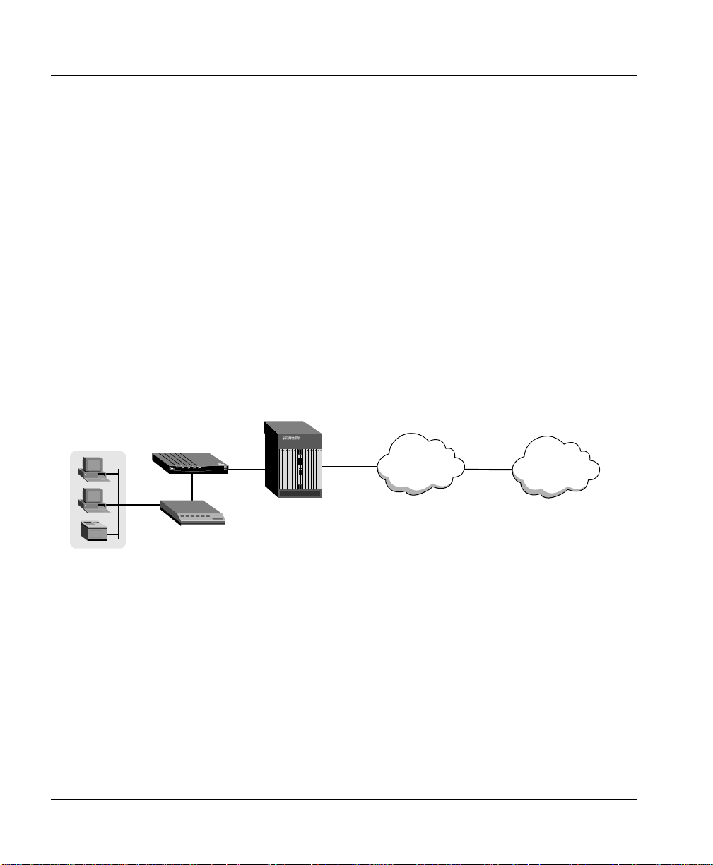
Figure 1-1 shows an example of how the CellPipe SDSU can fit into your network.
Figure 1-1. CellPipe SDSU and your network
Stinger
LAN
CellPipe SDSU
Router
SDSL
DS3 cells
OC3 cells
ATM network
Data
packets
Internet
CellPipe SDSU features
CellPipe SDSU units include the following features:
• Support for PPP, Frame Relay, or HDLC over ATM
• Support for data rates from 144 Kbps to 2.32 Mbps
• Static and dynamic IP routing
• Static IP bridging
• Support for Signaling Network Management Protocol (SNMP)
1-2 CellPipe™ SDSU Use r’s Guide

• Support for network address translation (NAT) to allow a single IP address to be
shared among multiple users
• Support for Domain Naming System (DNS) services
CellPipe SDSU configuration
A CellPipe SDSU is configured through a serial connection (see “Console setup” on
page 2-4) established between the unit and a computer running a compatible VT100
terminal emulation program (such as HyperTerminal). See Chapter 4, “Configuring a
CellPipe SDSU” and for more information on configuration.
CellPipe SDSU management
A CellPipe SDSU unit is managed through a menu-driven interface. A serial
connection between the unit and your computer, which must run VT100 terminal
emulation software, is used to display the menus and configuration information. You
select parameters and values from the appropriate menu(s) to change the
configuration. See Chapter 3, “Menus” for more information.
Introduction
CellPipe SDSU configura tio n
CellPipe™ SDSU User’s Guide 1-3


Setup
Checking box contents . . . . . . . . . . . . . . . . . . . . . . . . . . . . . . . . . . . . . . . . . . . . . 2-1
Connecting CellPipe SDSU cables. . . . . . . . . . . . . . . . . . . . . . . . . . . . . . . . . . . . 2-2
Checking CellPipe SDSU status lights. . . . . . . . . . . . . . . . . . . . . . . . . . . . . . . . . 2-3
Console setup . . . . . . . . . . . . . . . . . . . . . . . . . . . . . . . . . . . . . . . . . . . . . . . . . . . . 2-4
Logons . . . . . . . . . . . . . . . . . . . . . . . . . . . . . . . . . . . . . . . . . . . . . . . . . . . . . . . . . 2-4
This chapter provides instructions for verifying box contents, hardware installation,
checking unit status lights, establishing a serial connection, and logging on.
Checking box contents
Before you start setting up the unit, verify that your package contains the following
items:
1 CellPipe SDSU unit
2 SDSL WAN cable with RJ-11 modular plug connectors (blue)
3 DB-25-to-V.35 adapter cable
2
4 Warranty card
5 Start Here card
6 Power supply
Note: All CellPipe units are shipped with a power supply. Howe ver, European users
need to purchase an additional wall-outlet cab le because of reg ional variations in wall
CellPipe™ SDSU User’s Guide 2-1

Setup
Connecting CellPipe SDSU cables
outlets. Please check with your sales representative for the item specific to your unit.
See Figure 2-1.
Figure 2-1. Power supplies
U.S., Asia, Australia
power supply
European
power supply
Connecting CellPipe SDSU cables
Figure 2-2 shows the back panel of a CellPipe SDSU unit.
Figure 2-2. CellPipe SDSU back panel
To connect a CellPipe SDSU, proceed as follows:
1 Use a serial cable (not provided) to connect the port labeled TERMINAL to a
serial port on your computer.
2 Use the DB-25-to-V.35 cable (provided) to connect the DCE port to a ro uter with
a V.35 interface. See Figure 2-3.
3 Use the blue WAN cable (provided) to connect the WAN port on your unit to a
wall jack.
4 Power up your unit.
2-2 CellPipe™ SDSU Use r’s Guide

Figure 2-3. DB-25-to-V.35 cable
Setup
Checking CellPipe SDSU status lights
DB-25
Note: Apply power last. Doing so turns on the CellPipe unit as the unit has no power
switch.
V.35
Checking CellPipe SDSU status lights
Observe the activity pattern of the lights at the front of the CellPipe SDSU unit to
verify that it is connected properly.
Figure 2-4. CellPipe SDSU status lights
When all the cables are connected, verify that the status lights illuminate as follows:
• The pwr light is on initially and remains on. If it is not on, make sure the power
supply is properly connected.
• The act light blinks when there is data activity on the DCE port. Otherwise, it
remains off.
• The lnk light is on when the data transmit ready (DTR) control is active on the
DCE port. Otherwise, it remains off.
• The wan light blinks until a connection is established, and then it remains on.
• The con light remains off.
CellPipe™ SDSU User’s Guide 2-3

Setup
Console setup
Console setup
You need to set up a serial connection between the unit and your computer to access
the command-line interface and configure a CellPipe SDSU unit.
You need a 9-pin RS-232 serial cable to connect to the CellPipe unit through the
console port.
You also need a terminal emulation program, such as HyperTerminal, PROCOMM
PLUS, Zterm, or any other program that supports VT100 terminal emulation, to open
a session directly with the unit.
Set your communications software to connect with the following settings:
• Connection—Specify a direct connection from the unit to the computer.
• Serial port—Specify the serial port on the computer the software is to use.
• Terminal type—Specify VT100.
• Duplex—Specify Full. This is the default for most communications software.
• Bits per second—Specify 9600.
• Data bits—Specify 8.
• Parity—Specify None.
• Stop bits—Specify 1.
• Flow control—Specify None.
Logons
You can log on as supervisor, netwo rk administ rator , or user . As supervisor , yo u have
the authorization to change passwords for all three levels of access and can add on
new users.
Supervisor logon
The permanently configured supervisor login ID is Supervisor (case sensitive).
The default password for supervisor is
2-4 CellPipe™ SDSU Use r’s Guide
supervisor (case sensitive).

To change a supervisor password:
1 From the Main Menu, select
2 Select
3 Enter a password of up to 17 alphanumeric characters.
To add new user:
1 From the Main Menu, select
2 Select
3 Enter a new user ID of up to 17 alphanumeric characters.
Change Supervisor Password.
Change User ID.
Network administrator logon
The permanently configured administrator login ID is NetMan (case sensitive).
There is no initial value for the administrator password. Press Enter and you will be
logged on as administrator .
To specify an administrator password:
1 Press Enter.
2 From the Main Menu, select
3 Select
4 Enter a password of up to 17 alphanumeric characters.
Change NetMan Password.
Setup
Logons
Configure UserID and Password.
Configure UserID and Password.
Configure UserID and Password.
User logon
There are no initial values for the user ID and pa ssword. Press Enter twice to log on as
a user.
To specify a user ID and password:
1 Press Enter twice to log on as a user.
2 From the Main Menu, select
3 Enter a user ID value of up to 17 alphanumeric characters.
4 Enter a password of up to 17 alphanumeric characters.
CellPipe™ SDSU User’s Guide 2-5
Configure UserID and Password.


Menus
Main Menu . . . . . . . . . . . . . . . . . . . . . . . . . . . . . . . . . . . . . . . . . . . . . . . . . . . . . . 3-1
Navigating the menus. . . . . . . . . . . . . . . . . . . . . . . . . . . . . . . . . . . . . . . . . . . . . . 3-2
Main Menu items . . . . . . . . . . . . . . . . . . . . . . . . . . . . . . . . . . . . . . . . . . . . . . . . . 3-3
A menu system rooted in the Main Menu provides the primary interface to a CellPipe
SDSU unit. This chapter provides a summary of the menu items found under the
Main Menu. See Chapter 4, “Configuring a CellPipe SDSU,” for more detailed
information on the various menus used for configuring and managing the unit.
Main Menu
The Main Menu provides access to all other menus and appears on your VT100
terminal after you establish a connection to a CellPipe SDSU unit through the
HyperTerminal or other terminal emulation program. Depending on the access level
(Supervisor, Administrator, or User), some of the menus might not be visible.
Following is an example of the Main Menu when you log in as supervisor:
3
Main Menu
1. Reports Menu
2. Configure IP Router
3. Configure Interface
4. Configure UserID and Password
5. Quick Interworking Configuration
6. Manage Interworking Connections
7. System Utilities
CellPipe™ SDSU User’s Guide 3-1

Menus
Navigating the menus
8. Configure SNMP
N. Configure NAT
R. Reset System
ESC to log off menu system
Navigating the menus
A CellPipe SDSU unit is operated as a menu-driven system. You navigate by
selecting menus and operate the unit by setting parameters and issuin g commands
selected from the menus.
To select a menu item from any menu, enter the number or letter that identifies the
item.
For example, to select
Some menu items, when selected, display a submenu from which you select a value.
Others provide a text field. Type a value in the field and press Enter.
For example, to select a port for which you want to set an IP address, enter the
number of the port.
Select Port: [1-8] 1
Press the Esc key to return to the previous menu.
When you assign a value, the change is automatically saved. However, changes are
not activated until you reset the unit. Select Reset System from the Main Menu to
reset the unit and save changes.
1. Reports Menu, enter 1.
3-2 CellPipe™ SDSU Use r’s Guide

Main Menu items
This section summarizes the functions of menu items within the Main Menu.
Table 3-1. The Main Menu
Menu Functions
Reports Menu Display:
• Current configuration
• Network statistics
• Media statistics
• Route table
• System uptime
• Interface statistics
• PPP authorization entries
Configure IP Router Specify:
• Port IP address
• RIP version by port
• RIP poisoned reverse by port
• DNS client
• DHCP client
• Telnet server port
Menus
Main Menu items
Also:
• Delete IP address
• Enable or disable RIP
• Add or remove a static route
• Display a route table
CellPipe™ SDSU User’s Guide 3-3

Menus
Main Menu items
Table 3-1. The Main Menu (continued)
Menu Functions
Configure Interface Available WAN interfaces:
• Universal serial
• SDSL
Configure UserID and Password Change:
• User ID
• User password
• Administr ator password
• Supervisor password
Quick Interworking Configuration Set interworking connection:
• Pass-Through protoc ol
• FRF.8 or FRF.5
Manage Interworking Connections
3-4 CellPipe™ SDSU Use r’s Guide
• Add interworking connection
• Delete interworking connection
• Print interworking connections
• Default interworking connections

Table 3-1. The Main Menu (continued)
Menu Functions
Menus
Main Menu items
System Utilities
Configure SNMP Specify:
Perform:
• File transfer
• ACOS [acos.bin] updating
• Ping
• Route trace
• File system maintenance
• Entire system update
Specify:
• System defaults
• Console baud rate
• System settings saved as defaults
• System contact
• System name
• System location
• SNMP community
• SNMP trap host IP address
Also:
• Enable/disable SNMP.
CellPipe™ SDSU User’s Guide 3-5

Menus
Main Menu items
Table 3-1. The Main Menu (continued)
Menu Functions
Configure NAT Enable/disable:
• NAT debug messages.
• NAT translation by port
Specify:
• NAT TCP timeout
• NAT UDP timeout
• NAT port range
• NAT local server entry
Display:
• NAT statistics
• NAT connection table
• NAT connection details
• NAT local server table
Delete:
• IP address from NAT tables
• NAT local server entry
Reset System Restart system (a nd save configuratio ns).
3-6 CellPipe™ SDSU Use r’s Guide

Configuring a CellPipe SDSU
Configuring CPE or COE. . . . . . . . . . . . . . . . . . . . . . . . . . . . . . . . . . . . . . . . . . . 4-1
Configuring WAN interface . . . . . . . . . . . . . . . . . . . . . . . . . . . . . . . . . . . . . . . . . 4-2
Configuring the DCE interface. . . . . . . . . . . . . . . . . . . . . . . . . . . . . . . . . . . . . . . 4-5
Configuring static and default routes. . . . . . . . . . . . . . . . . . . . . . . . . . . . . . . . . . 4-5
Configuring RIP. . . . . . . . . . . . . . . . . . . . . . . . . . . . . . . . . . . . . . . . . . . . . . . . . . 4-7
Configuring interworking connection . . . . . . . . . . . . . . . . . . . . . . . . . . . . . . . . . 4-7
Configuring a DNS Server. . . . . . . . . . . . . . . . . . . . . . . . . . . . . . . . . . . . . . . . . . 4-9
Configuring DHCP. . . . . . . . . . . . . . . . . . . . . . . . . . . . . . . . . . . . . . . . . . . . . . . 4-10
Configuring NAT . . . . . . . . . . . . . . . . . . . . . . . . . . . . . . . . . . . . . . . . . . . . . . . . 4-10
Configuring SNMP. . . . . . . . . . . . . . . . . . . . . . . . . . . . . . . . . . . . . . . . . . . . . . . 4-12
This chapter provides general information for configuration of the various interfaces
and procedures for administrating a CellPipe SDSU unit.
4
Configuring CPE or COE
A CellPipe SDSU unit can be configured to operate either as customer premise
equipment (CPE) or as central office equipment (COE).
CellPipe™ SDSU User’s Guide 4-1

Configuring a CellPipe SDSU
Configuring WAN interface
To configure the unit for CPE or COE capability, proceed as follows:
1 From the Main Menu, select
2 Select SDSL.
3 Select
4 Select
Configure Physical Interface.
Toggle SDSL Mode (CO or CPE).
Configure Interface.
Configuring WAN interface
A CellPipe SDSU supports a SDSL connection on its WAN interface. This interface
on the unit can be configured for static and dynamic routing (see “Configuring static
and default routes” on page 4-5) and static bridging.
Bridging is automatically enabled when you start up the system. Bridging supports
one PVC connection and one DLCI connection and is automatically disabled when
routing is enabled.
In routing mode, the unit can support IP routing over Frame Relay and ATM through
seven PVC and seven DLCI connections. To enable routing, you need to configure
each PVC or DLCI connection and assign IP addresses to these connections and
specify a default route (see “Configuring a default route” on page 4-6). The unit
supports RIP and RIP 2 and does not support PAP and CHAP.
A CellPipe SDSU unit must be configured for routing to enable remote assignment of
IP addresses for either t he DC E or the WAN port. IP ro uti ng co nn ectio ns have a l evel
of built-in authentication, because the unit matches its own configured IP address to
the source IP address.
Using Autobaud
You need to enable Autobaud on the CellPipe SDSU to accept the rate available fro m
the remote DSLAM (digital subscriber line access multiplexer). On the centrol office
side (CO) set the user bandwidth allowed.
To enable autobaud mode, proceed as follows:
1 From the Main Menu, select
2 Select
4-2 CellPipe™ SDSU Use r’s Guide
SDSL from the available WAN interfaces.
Configure Interface.

3 Select Configure Physical Interface.
4 Select
5 Select to enable Autobaud Mode.
Enable/Disable Conexant Autobaud Mode.
Configuring for ATM
Transmission via SDSL on the CellPipe SDSU requires you to configure the WAN
interface to run either ATM or Frame Relay datalink protocol.
To configure for ATM, proceed as follows:
1 From the Main Menu, select
2 Select
3 Select
4 Select
Configuring PVCs
SDSL.
Configure Datalink Protocol.
ATM.
Configuring a CellPipe SDSU
Configuring WAN interface
Configure Interface.
When running ATM as your data link protocol, you need to configure each PVC
connection you use. You can have up to seven PVC connections with each PVC
establishing a port.
To configure a PVC port, proceed as follows:
1 From the Main Menu, select
2 Select
3 Select
4 Select
5 Enter VPI/VCI for each port you want to configure.
6 Select
SDSL.
Configure PVCs.
Add new PVC.
RFC 1483 (with LLC Encapsulation) for ATM encapsulation.
Configure Interface.
Payload scrambling
Y o u must enabl e payload scrambling when using ATM datalink p rotocol to co nnect to
a digital subscriber line access multiplexer (DSLAM), which usually has payload
scrambling set as de fault.
CellPipe™ SDSU User’s Guide 4-3

Configuring a CellPipe SDSU
Configuring WAN interface
To enable payload scrambling, proceed as follows:
1 From the Main Menu, select
2 Select
3 Select
4 Select
5 Enable Payload Scrambling.
SDSL.
Configure ATM Options.
Payload Scrambling.
Configure Interface.
Assigning IP addresses for PVC connections
You need to assign an IP address to each PVC connection on the WAN interface.
To assign an IP address, proceed as fo llows:
1 From the Main Menu, select
2 Select Configure Port IP Address.
3 Select
4 Select a port and assign the appropriate IP address.
SDSL.
Configure IP Router.
Configuring for Frame Relay
Transmission via the SDSL connection on the CellPipe SDSU requires you to
configure your WAN interface to run either ATM or Frame Relay datalink protocol.
To configure for Frame Relay, proceed as follows :
1 From the Main Menu, select
2 Select
3 Select
4 Select
SDSL.
Configure Datalink Protocol.
Frame Relay.
Configuring DLCIs
When using Frame Relay as your data link protocol, you need to configure DLCI
connections for each port you use. You can have up to seven DLCI connections with
each DLCI establishing a port.
4-4 CellPipe™ SDSU Use r’s Guide
Configure Interface.

To configure a DLCI port, proceed as fo llows:
1 From the Main Menu, select
2 Select Configure DLCIs.
3 Select
4 Enter a value for the DLCI.
5 Select
6 Select
Add New DLCI.
ATM RFC 1483 (Tunneling) for type of encapsulation.
Configure FR Options to configure fragmentation, maintenance
protocol, a nd congestion parameter s .
Configure Interface.
Assigning IP addresses for DLCI connections
You also need to assign an IP address to each DLCI on the WAN interface.
To assign an IP address, proceed as follows:
1 From the Main Menu, select
2 Select
3 Select
4 Select a port and assign the appropriate IP address.
Configure Port IP Address.
SDSL
Configure IP Router.
Configuring a CellPipe SDSU
Configuring the DCE interface
Configuring the DCE interface
The DCE interface on a CellPipe SDSU unit can be configured for static an d dynamic
routing. In routing mode, the DC E interface can support IP ro uting ov er Frame Relay.
To enable routing, you need to configure DLCI connections and assign IP addresses
to these connections. See “Configuring DLCIs” on page 4-4 and “Assigning IP
addresses for PVC connections” on page4-4.
Configuring static and default routes
A CellPipe SDSU unit can be configured to have a static (or default) route or have
RIP enabled for dynamic routing.
CellPipe™ SDSU User’s Guide 4-5

Configuring a CellPipe SDSU
Configuring static and default routes
Configuring a static route
You can configure a static route to a destination IP network, as well as the next-hop
router. If a profile specifies the destination address of a host on a remote subnet, but
the packets must be routed through an intermediary device to reach that host (and RIP
is not enabled), you must configure a static route specifying the intermediary device
as the next-hop router.
To configure a static route, proceed as follows:
1 From the Main Menu, select
2 Select
3 Select
4 Enter the destination address, the network mask, and the IP address of the
5 Press Y to save.
6 From the Main Menu, select
Add/Remove a Static Route.
Add a Static Route.
gateway.
Configuring a default route
Configure IP Router.
Reset System to put these changes into effect.
If no static route exists for the destination address of a packet, the unit forwards the
packet to the default route. A CellPipe CellPipeunit, however, drops packets for
which there is no configured default route.
To configure the default route, proceed as follows:
1 From the Main Menu, select
2 Select
3 Select
4 Type the gateway address for the default route.
5 Press Y to save.
6 From the Main Menu, select
4-6 CellPipe™ SDSU Use r’s Guide
Add/Remove a Static Route.
Add/Change the Default Route.
Configure IP Router.
Reset System to put these changes into effect.

Configuring a CellPipe SDSU
Configuring RIP
A router runs RIP to periodically broadcast the contents of its table to other routers
and gathers information from other routers to maintain a synchronized database. You
need to enable RIP if you do not want to manually enter all your routes.
To enable RIP in a CellPipe SDSU, proceed as follows:
1 From the Main Menu, select
2 Select
3 Enable RIP.
Enable/Disable RIP.
Configure IP Router.
Configuring interworking connection
A CellPipe SDSU can be configured for two interworking connections:
• Pass-through protocol
• FRF.5 or FRF.8 protocol
To select an interworking connection, proceed as follows:
1 From the Main Menu, select Quick Interworking Configuration.
2 Select either Protocol Pass-Through or FRF.5 or FRF.8.
Configuring RIP
Pass-through protocol
Pass-through protocol support s Frame Re lay traf fic over an ATM backbone. You need
to configure both the DCE and the WAN ports for Frame Relay datalink protocol.
Note: You cannot telnet in to the unit in the pass-through mode.
FRF.5
FRF .5 allows the tran sparent tunneling of Frame Relay traf fic and PVCs over an ATM
backbone. Intact Frame Relay frames are sent over the ATM network. There can be a
one-to-one relationship between Frame Relay and ATM PVCs or multiple Frame
Relay PVCs can be multiplexed into a single AT M PVC. You need to configure both
the DCE and the WAN ports for Frame Relay datalink protocol.
CellPipe™ SDSU User’s Guide 4-7

Configuring a CellPipe SDSU
Configuring interworking connection
FRF.8
FRF.8 converts Frame Relay traffic to ATM traffic for transmission over an ATM
backbone. There is always a one-to-one relationship between Frame Relay and ATM
PVCs. You have to configure both the DCE port and th e WAN port for ATM datalink
protocol. The DCE port must have an RFC 1490 DLCI and the SDSL must have an
RFC 1483 PVC.
Configuring for FRF.5 or FRF.8
Prior to configuring for FRF.5 or FRF.8, be sure you correctly configure your DCE
and WAN ports for the correct WAN interface.
To configure for FRF.5 or FRF.8 interworking connection, proceed as follows:
1 From the Main Menu, select
2 Select
3 Enter
4 Enter n to set up LIM for FR.
5 Enter n to set up SDSL ATM interface.
6 Select
7 Select the Frame Relay interface and port for the interworking connection.
8 Select the ATM interface and port for the interworking connection.
9 Select FRF.5 or FRF.8.
FRF.8 or FRF.5.
n to set up USI for Frame Relay.
Add Interworking Connection.
Quick Interworking Configuration.
FRF.5
Selecting FRF.5 brings up the FRF.5 DE Mapping menu where you set how the unit
maps the discard eligible (DE) bit of incoming Frame Relay frames to the service
specific convergence sublayer (SSCS) and the ATM Cell Loss Priority Indication
(CLPI) bit.
• Select
• Select
4-8 CellPipe™ SDSU Use r’s Guide
Set FR-SSCS, ATM = 0 to set the Frame Relay SSCS header’s DE
bit according to the frame’s DE bit and the ATM Cell Loss Priority Indication
(CLPI) bit to 0.
Set FR-SSCS, ATM = 1 to set the Frame Relay SSCS header’s DE
bit according to the frame’s DE bit and the ATM CLPI’s bit to 1.

• Select Use both FR-SSCS and A TM to map the SSCS DE bit to the DE bit and to
every ATM CLPI cell that makes up the current frame.
FRF.8
Selecting FRF.8 brings up the FRF.8 Translation menu.
• Select
• Select
• Select
• Select
True to execute interworking translation. (Selecting False will result in
transparent transmission.)
Always 0 to set the Frame Relay SSCS header’s DE bit according to
the frame’s DE bit and the ATM CLPI’s bit to 0.
Always 1 to set the Frame Relay SSCS header’s DE bit according to the
frame’s DE bit and the ATM CLPI’s bit to 1.
Map FR DE to ATM CLPI to map the SSCS DE bit to the DE bit and
to every ATM CLPI cell that makes up the current frame.
Configuring a DNS Server
Domain Naming System (DNS) is a mechanism for translating symbolic names to IP
addresses. T o make DNS services available to a CellPipe SDSU, you must specify the
IP address of a DNS server.
Configuring a CellPipe SDSU
Configuring a DNS Server
To specify a DNS server’s IP address, proceed as follows:
1 From the Main Menu, select
2 Select
3 Select Set DNS Server IP Address.
4 Enter the IP address of the DNS server.
5 Reset the unit for these changes to take effect.
You can also use the DNS Client menu to specify the DNS server time-out value. The
default value is 5 seconds.
CellPipe™ SDSU User’s Guide 4-9
Configure DNS Client.
Configure IP Router.

Configuring a CellPipe SDSU
Configuring DHCP
Configuring DHCP
You can configure a CellPipe SDSU to be a dynamic host configuration protocol
(DHCP) client and allow the unit to get temporary IP addresses from centrally
administered servers. A unit must be configured as a router for it to function as a
DHCP client. IP addresses can be assigned to ports on either the WAN or the DCE
interface.
To configure a CellPipe SDSU to be a DHCP client, follow these steps:
1 From the Main Menu, select
2 Select
3 Select the appropriate interface and port number.
4 Enter Y to enable DHCP for the port. Repeat for each port that will be enabled
5 Reset the unit for these changes to take effect.
Configure DHCP Client.
for DHCP.
Configuring NAT
Configure IP Router.
There are two steps to the configuration for network address translation (NAT) on a
CellPipe SDSU. First, you have to enable NAT translation on those ports that you
want to run NAT. Then you have to specify a NAT configuration for each of those
ports.
Enabling NAT translation by port
To enable NAT translation by port, proceed as follows:
1 From the Main Menu, select
2 Select
3 Select
4 Select each port for which you want to enable NAT and enter y.
5 Reset the unit for these changes to take effect.
Note: NAT automatically turns off RIP so the address is not propagated to the
Internet or remote networks.
4-10 CellPipe™ SDSU User’s Guide
Enable/Disable NAT Translation by Port.
SDSL.
Configure NAT.

Specifying NAT configuration by port
After enabling the ports for NAT, you are ready to specify NAT configuration by port.
To specify NAT configuration by port, proceed as follows:
1 From the Main Menu, select
2 Select Configure NAT Local Server Entry.
3 When prompted for Local Server Entry to Configure, enter
Note: A total of 10 server entries can be configured in the local server entry.
4 Enter the NAT Local Server Translated IP address.
(This is the IP address that will be translated to a TCP or UDP port number when
the unit is operating in NAT mode.)
5 Type the number of the port that will be translated.
6 Type the number of the port that it will be translated to.
7 Select either TCP or UDP protocol.
8 Repeat step 1 through step 6 for each port you want to configure.
Configure NAT.
Configuring a CellPipe SDSU
Configuring NAT
1.
Other NA T menu items
The following are menus items for various NAT-related parameters:
• Use the Configure NAT Port Range parameter to specify the lowest and highest
port values. Port numbers to assign to IP connections has a low range from 1to
65,534 and a high range from 50,000 to 65,535. The default low value is 50,000
and the default high value is 65,535.
• Select
• (Optional) Use the Configure NAT TCP Time-out or the Configure NAT UDP
CellPipe™ SDSU User’s Guide 4-11
Delete NAT Local Server Entry under the NAT Configuration
menu to delete any entries you have configured.
Time-out parameters to change time-out values for TCP or UDP, respectively.
The values range from 60 to 3600 seconds. The default time-out value is 300
seconds.

Configuring a CellPipe SDSU
Configuring SNMP
Configuring SNMP
A CellPipe SDSU supports simple network management protocol (SNMP). An
SNMP management station can query the unit, set some parameters, sound alarms
when certain conditions appear in the unit, and so forth.
To configure SNMP, proceed as follows:
1 From the Main Menu, select
2 Select
3 Enter a value for each of the following (up to 39 alphanumeric characters):
4 Reset the unit for these changes to take effect.
Enable/Disable SNMP, then select y to enable SNMP.
• System Contact
• System Location
• System Name
• SNMP Community
• SNMP Trap Host IP Address.
Configure SNMP.
4-12 CellPipe™ SDSU User’s Guide

Upgrading System Software
Preparing to upgrade. . . . . . . . . . . . . . . . . . . . . . . . . . . . . . . . . . . . . . . . . . . . . . . 5-1
Obtaining software. . . . . . . . . . . . . . . . . . . . . . . . . . . . . . . . . . . . . . . . . . . . . . . . 5-2
Backing up your configuration. . . . . . . . . . . . . . . . . . . . . . . . . . . . . . . . . . . . . . . 5-2
Loading software . . . . . . . . . . . . . . . . . . . . . . . . . . . . . . . . . . . . . . . . . . . . . . . . . 5-2
CellPipe SDSU units support a high-speed serial interface for RS-530 and V.35 data
communication instead of the traditional Ethernet interface. You cannot upgrade
software by the traditional method of downloading software from a TFTP server set
up on your network. This chapter provides instruction for upgrading software on a
CellPipe SDSU unit.
Preparing to upgrade
To upgrade the system software, you need to have a TFTP server application on your
computer to which you download th e appropriate sof tware release from the Lucent ftp
server (see “Obtaining software” on page 5-2). You then load the sof tware to a
CellPipe SDSU unit through a serial connection set up between your computer and
the TERMINAL console on the unit. See “Console setup” on page 2-4.
5
CellPipe™ SDSU User’s Guide 5-1

Upgrading System Software
Obtaining software
Obtaining software
You can obtain the latest software release from the Lucent Technologies eSight™
Service Center at http://www.esight.com.
Note: Be sure you use the correct loads to upgrade. Your unit can lose all or part of
its configuration if the wrong loads are used.
!
Caution: Do not upgrade to an earlier software version. Newer units will not
function properly when older software is loaded.
Backing up your configuration
Before loading new software, save the current configuration by transferring a copy of
the
Config.st file to your computer. Make sure you have established a serial
connection between the device and your computer, as described in “Console setup”
on page 2-4. Then proceed as follows:
1 From the Main Menu, select
2 Select
3 Select
4 Enter Config.st when prompted for name of the file to be transferred.
5 Select Send.
6 Enter
You are prompted when the file transfer has been successfully completed.
File Transfer Utility.
Send or Receive via XMODEM.
no when prompted to change console speed.
System Utilities.
Loading software
Make sure you have set up a serial connection between you r co mpu ter and the d evice
as described in “Console setup” on page 2-4. Follow the procedure below to transfer
each file to the unit.
Note: Reserve the
ACOS [acos.bin]
command to transfer this file.
5-2 CellPipe™ SDSU Use r’s Guide
acos.bin file as the last file to be transferred. Use the Update
command instead of the File Transfer Utility

Upgrading System Software
Loading software
To load software, proceed as follows:
1 From the Main Menu, select
System Utilities.
2 Select File Transfer Utility.
3 Select
Send or Receive via XMODEM.
4 When prompted, enter the name of the file to be transferred.
5 Enter
no when prompted to change console speed.
6 The following message appears:
Now Receiving ff...
This message indicates the unit is ready to receive the file.
7 At the HyperTerminal menu bar, select
Transfer > Send File.
8 In the Send File window, set the Protocol field to Xmode, browse to and select
the file to transfer, and click Send.
You are prompted when the file transfer has been successfully completed.
Note: Perform step 8 quickly or you will time out.
9 Repeat step 1 through step 8 for each file in the set except
10 Select
Update ACOS [acos.bin] to transfer the acos.bin file.
11 To reset the system when all the files have been loaded, select
acos.bin.
Hard Reset
under System Utilities in the Main Menu or do a power plug pull.
CellPipe™ SDSU User’s Guide 5-3


Hardware Specifications
CellPipe SDSU units have the following hardware specifications.
Physical connectors RJ-11 for xDSL WAN
DB-25 (USI) connector
Power input 18Vdc @ 1A
Dimensions 3.2 cm x 8.1 cm x 10.5 cm (HxWxL )
Weight 90 g
Humidity 0–90%, noncondensing
Operating temperature 32–122° F (0–50° C)
CellPipe™ SDSU User’s Guide A-1


FCC Regulations
FCC Part 15 Notice . . . . . . . . . . . . . . . . . . . . . . . . . . . . . . . . . . . . . . . . . . . B-1
IC CS-03 Notice. . . . . . . . . . . . . . . . . . . . . . . . . . . . . . . . . . . . . . . . . . . . . . B-1
FCC Part 15 Notice
!
Warning: This equipment has been tested and found to comply with the limits for a
Class B digital device, pursuant to Part 15 of the FCC rules. Thes e limits are designed
to provide reasonable protection against harmful interference when the equipment is
operated in a residential environment. This equipment generates , uses, and c an radiate
radio frequency energy, and, if not installed and used in accordance with the
instruction manual, may cause harmful interference to radio communications.
Operation of this equipment in a residential area is unlikely to cause harmful
interference. But if it does, the user will be required to correct the interference at his
or her own expense.
The authority to operate this equipment is conditioned by the requirement that no
modifications will be made to the equipment unless the changes or modifications are
expressly approved by Lucent Technologies.
IC CS-03 Notice
The Industry Canada label identifies certified equipment. This certification means
that the equipment meets certain telecommunications network protective, operational,
and safety requirements as prescribed in the appropriate Terminal Equipment
CellPipe™ SDSU User’s Guide B-1

FCC Regulations
IC CS-03 Notice
Technical Requirements document(s). The Department does not guarantee that the
equipment will operate to the user’s satisfaction.
Before installing this equipment, users should make su r e that it is per m issible to be
connected to the facilities of the local telecommunications company. An acceptable
method of connection must be used to install the equipment. The customer should be
aware that compliance with the above conditions may not prevent degradation of
service in some situations.
Repairs to certified equipment should be coordinated by a representative designated
by the supplier. Any repairs or alterations made by the user to this equipment, or
equipment malfunctions, ma y giv e the tel ecommun ications company cause to r equest
the user to disconnect the equipment.
Users should ensure for their o wn p rotection that th e electrical gr oun d connections of
the power utility, telephone lines, and internal metallic water pipe system, if present,
are connected together. This precaution may be particularly important in rural areas.
Warning: Users should not attempt to make such connections themselves, but
should contact the appropriate electric inspection authority, or electrician, as
appropriate.
B-2 CellPipe™ SDSU User’s Guide
 Loading...