


CellPipe™ IAD 4A and
CellPipe
Hardware Installation Guide
™ IAD 8T
Part Number : 7820-0791-001
For software version 2.0
January 2001

Copyright © 2001 Lucent Technologies Inc. All rights reserved.
This material is protect ed by the copy right laws of the United States and othe r countries. It may not be reproduced, distr ibuted, or
altered in any fashi on by any entity (either i nternal or external to Lu cent Technologies), except in accorda nce with applicable
agreements, c ontracts, or licen sing, w ithout t he expr ess writte n consen t of L ucent Technologies. For permi ssion to r eproduce or
distribute, please emai l you r request to techpubs@ascend.com.
Notice
Every effort was made to ensure that the information in this document was complete and accurate at the time of printing, but information is subject to change.
Safety, Compliance, and Warranty Information
Before handling any Lucent Ac ce ss N e tworks hardware product, read the E dge Access Safety and Compliance Gui de included in
your product packag e. See that guide also to determine how produ cts comply with the elec tromagnetic interfer ence (EMI) and
network comp atibility requirements of you r country. See the warranty card included in your product package fo r the limited
warranty that Lucent Technologies provid es for i ts prod ucts.
Security Statement
In rare instances, unauthorized individuals make connections to the telecommunications network through the use of access
features.
Copyrights for Third-Party Software Included in Lucent Access Networks Software Products
C++ Standard Template Library sof tware copyright© 1 994 Hewlett-Packard Company and co pyright© 1997 Sil icon Graphics.
Permission to use, copy, modify, distribute, and sell this software and its documentation for any purpose is hereby granted without
fee, provided that the above copyright notice ap pear in all copies and that both that copyright notic e and this permission no tice
appear in support ing documentation. Neit her Hewlett-Packard nor Si licon Graphics makes any re presentations about the suit ability of this software for any purpose. It is provided “a s is” w it hout express or implied warra nt y.
Berkeley Software D istribu tion ( BSD) UNIX sof tware copyri gh t© 19 82, 1986, 1988, 1993 Th e Reg ents of Califor nia. All right s
reserved. Redistribution and use in source and binary forms, with or without modification, are permitted provided that the
following conditions are met: 1. Redistribut io ns of source code must retain th e a bove copyright notice, thi s list of conditions, and
the following disclaimer. 2. Redistributions in binary form must reprod uc e the ab ove copy right noti ce, this list of co ndition s, an d
the following disclai mer in the docume ntation and/or other materials pro vided with the di stribution. 3. All ad vertising mat erials
mentioning features o r use of this so ftware must d isplay the f ollowing ac knowledge ment: This p roduct in cludes soft ware dev eloped by the Universit y of California, B erkeley, and its contributors. 4. Neithe r the name of th e University no r the names of its
contributors may be used to endorse or promote prod uc ts de rived from this software without spec ific prior written permission.
THIS SOFTWARE IS PROVIDED BY THE REGENTS AND CONTRIBUTORS “AS IS” AND ANY EXPRESS OR IMPLIED
WARRANTIES, INCLUDING, BUT NOT LIMITED TO, THE IMPLIED WARRANTIES OF MERCHANTABILITY AND
FITNESS FOR A PARTICULAR PURPOSE ARE DISCLAIMED. IN NO EVENT SHALL THE REGENTS OR CONTRIBUTORS BE LIABLE FOR ANY DIRECT, INDIRECT, INCIDENTAL, SPECIAL, EXEMPLARY, OR CONSEQUENTIAL
DAMAGES (INCLUDING, BUT NOT LIMITED TO, PROCUREMENT OF SUBSTITUTE GOODS OR SERVICES; LOSS OF
USE, DATA OR PROFITS; OR BUSINESS INTERRUPTION) HOWEVER CAUSED AND ON ANY THEORY OF
LIABILITY, WHETHER IN CONTRACT, STRICT LIABILITY, OR TORT (INCLUDING NEGLIGENCE OR OTHERWISE)
ARISING IN ANY WAY OUT OF THE USE OF THIS SOFTWARE, EVEN IF ADVISED OF THE POSSIBILITY OF SUCH
DAMAGE.
Feedback
Lucent Technologies appreciates your comments, either positive or negative, about this manual. Please send them to
techpubs@ascend.com.
Lucent Technologies

Trademarks
4ESS, 5ESS, A Network of Expertise, AnyMedia, APX 8000, AqueView, AUDIX,
B-STDX 8000, B-STDX 9000, ...Beyond Compare, CaseView, Cajun, CajunDocs,
CAJUNVIEW, Callmaster, CallVisor, CBX 5 00, CellPipe, ChoiceNet, ClearReach,
ComOS, cvMAX, DACScan, Dacsmate, Datakit, DEFINITY, Definity One,
DSLMAX, DSLTerminator, DSLPipe, DSLTNT, Elemedia, Elemedia Enhanced,
EMMI, End to End Solutions, EPAC, eSight, ESS, EVEREST,
Gigabit-scaled campus networking, Globalview, GRF, GX 250, GX 550,
HyperPATH, Inferno, InfernoSpaces, Intragy, IntragyAccess, IntragyCentral, Intuity,
IP Navigator, IPWorX, LineReach, LinkReach, MAX, MAXENT, MAX TNT,
Multiband, Multiband PLUS, Multiband RPM, MultiDS L , MultiVoice, MultiVPN,
Navis, NavisAccess, NavisConnect, NavisCore, NavisRadius, NavisXtend, NetCare,
NetLight, NetPartner, OneVis io n, Op en Systems Innovations, OpenTrunk, P550,
PacketStar, PathStar, Pinnacle, Pipeline, PMVision, PortMaster, SecureConnect,
Selectools, Series56, SmoothConnect, Stinger , SYSTIMAX, True Access, WaveLAN,
WaveMANAGER, WaveMODEM, Web Xten d, and
Where Network Solutions Never End are trademarks of Lucent Technologies Inc.
Advantage Pak, Advantage Services, AnyMedia, ...Beyond Compare,
End to End Solutions, Inter.NetWorking, MAXENT, and
NetWork Knowledge Solutions are service marks of Lucent Technologies Inc. Other
trademarks, service marks, and trade names mentioned in this publication belong to
their respective owners.
Trademarks
Ordering In formation
You can order the most up-to-date product information and computer-based training
online at http://www.lucent.com/ins/bookstore.
Customer Service
To obtain product and service information, software upgrades, and technical
assistance, visit the eSight™ Service Center at http://www.esight.com. The
center is open 24 hours a day, seven days a week.
CellPipe IAD 4A and CellPipe IAD 8T Hardware Installation Gu ide iii

Customer Service
Finding information and software
The eSight Service Center at http://www.esight.com provides technical
information, product infor mation, and descriptions of a vailable services . Log in and
select a service. The eSight Service Center also provides software upgrades, release
notes, and addenda. Or you can visit the FTP site at ftp://ftp.ascend.com for
this information.
Obtaining technical assistance
The eSight™ Service Center at http://www.esight.com provides access to
technical support. You can obtain technical assistance through email or the Internet,
or by telephone.
If you need to contact Lucent Technologies for assistance, make sure that you have
the following information available:
• Active contract number, product name, model, and serial number
• Software version
• Software and hardware options
• If supplied by your carrier, service profile identifiers (SPIDs) associated with
your line
• Your local telephone company’s switch type and op erat i ng mo de, su ch as AT&T
5ESS Custom or Northern Telecom National ISDN-1
• Whether you are routing or bridging with your Lucent product
• Type of computer you are using
• Description of the problem
Obtaining assistance through email or the Internet
If your services agreement allows, you can communicate directly with a technical
engineer through Email Technical Support or eSight Live chat. Select one of these
sites when you log in to http://www.esight.com.
Calling the technical assistanc e center (TAC)
If you cannot find an answer through the tools and information on eSight or if you
have a very urgent need, contact TAC. Access the eSight Service Center at
iv CellPipe IAD 4A and CellPipe IAD 8T Hardware Installation Guide

http://www.esight.com and click Contact Us below the Lucent
Technologies logo for a list of telephone numbers inside and outside the United
States.
You can alternatively call (800) 272-3634 for a menu of Lucent services, or call
(510) 769-6001 for an operator. If you do not have an active services agreement or
contract, you will be charged for time and materials.
Important safety instructions
1 Read and follow all warning notices and instructions marked on the product or
included in the manual.
2 There are no operator serviceable parts within the unit. Refer all servicing to
trained service personnel.
3 Product installation should be performed by trained service personnel only.
Important safety inst ru ctions
4 Install only in restricted-access areas in accordance with UL1950, C22.2 No. 950,
and IEC60950
5 The maximum recommended operating ambient is 122° F (50° C). Allow
sufficient air circulation or space between units when installed in a closed or
multiple-rack assembly.
6 Slots and openings in the cabinet are provided for ventilation. To ensure reliable
operation of the product and to protect it from overheating, these slots and
openings must not be blocked or covered. Installation without sufficient airflow
can be unsafe.
7 Equipment mounted in a rack should be distributed to prevent a possible
hazardous condition due to uneven loading. The rack should safely support the
combined weight of all equipment. This product weighs 8 lbs.
8 The power source has to be adequately rated to assure safe operation of the
equipment. The building installation and/or power source must provide overload
protection.
9 Protective earth (PE) connection is essential to ensure safe operation before
connecting to the power supply and telecommunication network. Do not defeat
the purpose of the grounding-type plug by modifying the plug or using an
adapter. Use an outlet tester or a voltmeter to check the ac receptacle for the
presence of earth ground. If the receptacle is not properly grounded, the
CellPipe IAD 4A and CellPipe IAD 8T Hardware Installation Gu ide v

Important safety instructions
installation must not proceed until a qualified electrician has corrected the
problem.
If the power supply is fed from a power source with no protective-earthing path
(such as in certain Nordic countries), connect an earth-grounded copper wire to
the dedicated wiring terminal marked with (PE symbol) on the chassis. The
minimum size of the wire for a Pipeline unit with rated input current not
exceeding 6A is AWG 18 and cross-sectional area 0.75 mm
Models with ac power inputs are intended for use with a single-phase three-wire
power cord (which includes earthing conductor).
For models with dc power inputs, the protective earth connection must be
established by using the dedicated earthing terminal marked with the PE symbol
or, if provided, the earthing pin of the input terminal block.
10 Models with dc power inputs must be connected to a -48V dc supply source that
is electrically isolated from the ac source in accordance with UL19 50, C22.2 No.
950, and IEC60950.
11 For products installed in Nordic countries (except Ce ntral Office equipment), a
type B plug or permanent connection must be used for connections to the main
power supply.
2
.
12 Before installing wires to the dc power terminal block, verify that these wires are
not connected to any power source. Installing live wires (that is, wires connected
to a power source) is hazardous.
13 Do not allow anything to rest on the power cord, and do not locate the product
where people will walk on the power cord.
14 Do not attempt to service this product yourself. Opening or removing covers can
expose you to dangerous high voltage poi nt s or ot her ri s ks. Refer all servicing to
qualified service personnel.
15 General purpose cables are provided with this product. Special cables, which
might be required by the regulatory inspection authority for the installation site,
are the responsibility of the customer.
16 When installed in the final configuration, the product must comply with the
applicable safety standards and regulatory requirements of the countr y in which
it is installed. If necessary, consult with the appropriate regulatory agencies and
inspection authorities to ensure compliance.
17 A rare phenomenon can create a voltage potential between the earth grounds of
two or more buildings. If products installed in separate buildings are
interconnected, the voltage potential might cause a hazardous condition. Consult
vi CellPipe IAD 4A and CellPipe IAD 8T Hardware Installation Guide

Important safety inst ru ctions
a qualified electrical consultant to determine whether or not this phenomenon
exists.
In addition, if the equipment is to be used with telecommunications circuits, take the
following precautions:
• Never install telephone wiring during a lightning storm.
• Never install telephone jacks in wet locations unless the jack is s pecifically
designed for wet locations.
• Never touch uninsulated telephone wires or terminal s unless the telephone line
has been disconnected at the network interface.
• Use caution when installing or modifying telephone lines.
• Avoid using equipment connected to telephone lines (other than a cordless
telephone) during an electrical storm. There is a remote risk of electric shock
from lightning.
• Do not use a telephone or other equipment connected to telephone lines to report
a gas leak in the vicinity of the leak.
!
!
!
Warning: To reduce the risk of fire, communication cable conductors must be
26 AWG (0.13 mm
Avertissement: Afin de réduire les risques d'incendie, les fils conducteurs du
câble de communication doivent être d'un calibre minimum de 26 AWG
(American Wire Gauge), c'est-à-dire d'un minimum de 0,13 mm².
Warnung: Um Feuer-Risiko zu reduzieren, müsssen die Querschnitte der
Kommunikationskabel-Leiter 0,13 mm² oder größer sein.
2
) or larger.
CellPipe IAD 4A and CellPipe IAD 8T Hardware Installation Gu ide vii


Contents
Trademarks .............................................................................................................. i ii
Ordering Information ............................................................................................... iii
Customer Service ..................................................................................................... iii
Important safety instructions ..................................................................................... v
Introduction ............................................................................. 1
New CellPipe products .............................................................................................. 1
Lucent TURN-UP ...................................................................................................... 2
Serial connection ....................................................................................................... 2
Configuring your communications software ............................................................. 2
Preparing to upgrade .............................. ....................................... ...... ....................... 3
Locating the software binary file(s) ......................................................................... 3
Power supply ............................. ...... ........................................ ..... ............................. 4
CellPipe IAD 4A ....................................................................... 5
Connecting a CellPipe IAD 4A unit .......................................................................... 5
Checking the activity of CellPipe IAD 4A status lights ............................................ 6
Configuring a CellPipe IAD 4A unit ......................................................................... 8
CellPipe IAD 8T ....................................................................... 9
Connecting a CellPipe IAD 8T unit .......................................................................... 9
Checking the activity of CellPipe IAD 8T status lights .......................................... 10
Configuring a CellPipe IAD 8T unit ....................................................................... 12
Connector Pinouts ............................. .... ..... .......................... 15
TERMINAL pinouts ................................................................................................ 15
CellPipe IAD 4A and CellPipe IAD 8T Hardware Installation Gu ide ix

Contents
10/100 LAN connector pinouts ............................................................................... 15
T1 Connector pinouts .............................................................................................. 16
ADSL connector pinouts ......................................................................................... 16
FCC Regulations .................................................................. 17
FCC Part 15 Notice .................................................................................................. 17
IC CS-03 Notice ...................................................................................................... 18
x CellPipe IAD 4A and CellPipe IAD 8T Hardware Installation Guide

Introduction
New CellPipe products. . . . . . . . . . . . . . . . . . . . . . . . . . . . . . . . . . . . . . . . . . . . . . . 1
Lucent TURN-UP. . . . . . . . . . . . . . . . . . . . . . . . . . . . . . . . . . . . . . . . . . . . . . . . . . . 2
Serial connection . . . . . . . . . . . . . . . . . . . . . . . . . . . . . . . . . . . . . . . . . . . . . . . . . . . 2
Configuring your communications software . . . . . . . . . . . . . . . . . . . . . . . . . . . . . . 2
Preparing to upgrade. . . . . . . . . . . . . . . . . . . . . . . . . . . . . . . . . . . . . . . . . . . . . . . . . 3
Locating the software binary file(s). . . . . . . . . . . . . . . . . . . . . . . . . . . . . . . . . . . . . 3
Power supply . . . . . . . . . . . . . . . . . . . . . . . . . . . . . . . . . . . . . . . . . . . . . . . . . . . . . . 4
New CellPipe products
The CellPipe IAD 4A and CellPipe IAD 8T are now part of the CellPipe™ product
line that run the IAD (Integrated Access Device) v . 2.0 software. These are integrated
access devices supporting both voice and data communications.
This Hardware Installation Guide provides information for conn ecting these new
units to your computer . For additional information, refer to the CellPipe™ IAD User’s
Guide.
CellPipe IAD 4A and CellPipe IAD 8T Hardware Installation Gu ide 1

Introduction
Lucent TURN-UP
Lucent TURN-UP
The CellPipe IAD 4A and CellPipe IAD 8T units support the Lucent TURN-UP
automated provision ing syst em. TURN-Up is enabled wh en a user power s up hi s unit,
which is then automatically configured via the configuration server located at his
Internet Service Provider (ISP). TURN-UP eliminates the need for user con figuration
of units and provides centralized management of configuration information.
!
Caution: If you attempt to manually configure the unit, a Delete Management Port
message will appear. If you select this option, the Lucent TURN-UP feature will be
disabled to enable you to reconfigure the unit.
Serial connection
You need to establish a serial connection to upgrade software and manually configure
the CellPipe units. Connect a serial cable (a serial communication cable designed for
connecting an external device) from your computer to the CellPipe unit. The cable
must be a high-speed cable that supports t he hardware h andshakin g technique used by
almost all recently manufactured modems. The cable must have the appropriate
connector for connection to a serial communication port on your computer and a
DB-9 connector for connection to the TERMINAL port on the CellPipe unit.
Configuring your communications software
Use a communications program (such as HyperTerm, PROCOMM PLUS, Zterm, or
any other program that supp orts VT100 terminal emulati on) to open a sessi on directly
with the port to which the IAD unit is connected.
Configure your communications software with the following settings. If you are not
already familiar with the settings listed, see the documentation that accompanies your
communications software. If you are using the software for the first time, going
through an online or printed tutorial is a good way to get started.
• Direct connection—Indicate that a serial cable connects the IAD directly to the
computer.
2 CellPipe IAD 4A and CellPipe IAD 8T Hardware Inst allation Guide

Introduction
Preparing to upgrade
• Serial port—Specify which of the computer’s s erial ports t he software u ses. If the
only serial port available is currently used by an internal modem, you may need
to use your computer’s setup software to specify an external connector for the
port that will be used in place of the internal modem. In some cases, you also
may need to remove the modem. See the manual for the modem and your
computer’s user manual for details.
• Terminal type—Specify VT100.
• Duplex—Most communications software support full-duplex transmission by
default. If given a choice, set Full duplex.
• Bits per second—Specify 9600.
• Data bits—Specify 8.
• Parity—Specify None.
• Stop bits—Specify 1.
• Flow control—Disable software flow control (XON/XOFF) and, if possible,
hardware flow control (RTS/CTS).
When you establish the connection, the command-line interface appears.
Preparing to upgrade
Set up a TFTP server on the network that is accessible by your CellPipe unit prior to
upgrading the software. Also, configure an IP address on the 10BaseT port of the
CellPipe unit and test the connection to the TFTP server by pinging the server.
Locating the software binary file(s)
!
Caution: Do not upgrade to an earlier software version. Uploading older software
causes the unit to loose configuration, and you will have to return it for replacement.
You can locate the software binary file (or collection of software binary files) for the
IAD CellPipes at
ftp://ftp.ascend.com/pub/Software-Releases/CellPipe.
CellPipe IAD 4A and CellPipe IAD 8T Hardware Installation Gu ide 3

Introduction
Power supply
The software loads for each CellPipe unit are different. Make certain that you
download the correct file. If you use the wrong file to upgrade, your unit will stop
functioning and you will have to restore your configuration from a backup.
Extract and save the appropriate file to the TFTP boot directory from which you will
upgrade your unit.
Power supply
All CellPipe units are shipped with a power supply. However, Eu ropean users need to
purchase an additional wall outlet cable due to the regional variations in wall outlets.
Please check with your Sales Representative for the power supply and cab les required
for your environment. Refer to the illustrati ons below.
Domestic power supply European power supply
4 CellPipe IAD 4A and CellPipe IAD 8T Hardware Inst allation Guide

CellPipe IAD 4A
Connecting a CellPipe IAD 4A unit. . . . . . . . . . . . . . . . . . . . . . . . . . . . . . . . . . . . . 5
Checking the activity of CellPipe IAD 4A status lights. . . . . . . . . . . . . . . . . . . . . . 6
Configuring a CellPipe IAD 4A unit . . . . . . . . . . . . . . . . . . . . . . . . . . . . . . . . . . . . 8
The CellPipe IAD 4A supports four POTS (plain old telephone service) lines over
ATM (Asynchronous Transfer Mode), PPP (Point-to-Point Protocol) over ATM,
Frame Relay or HDLC (High-Level Data Link Control) over an ADSL (asymmetrical
digital subscriber line) WAN interface. This unit supports asymmetrical transmission
and receive downstream rates of 64 Kbps to 8.1 Mbps and upstream rates of 64 Kbps
to 800 Kbps.
Connecting a CellPipe IAD 4A unit
The CellPipe IAD box you receive contains the following items:
1 CellPipe IAD unit
2 10BaseT Ethernet crossover cable (yellow)
3 ADSL WAN cable with RJ-11 modular plug connectors (blue)
4 Power supply
5 CellPipe™ IAD User’s Guide
6 Hardware Installation Guide
CellPipe IAD 4A and CellPipe IAD 8T Hardware Installation Gu ide 5

CellPipe IAD 4A
Checking the activity of CellPipe IAD 4A status lights
7 Warranty card
To connect to the CellPipe IAD 4A unit, proceed as follows:
1 Connect one end of the yellow Ethernet cable to the port labeled LAN on your
unit and the other end to the Ethernet adapter on your computer.
Note: To connect the CellPipe unit to an Ethernet hub, use a straight-through
Ethernet cable (not supplied).
2 Connect one end of the blue WAN cable to the port labeled WAN and plug the
other end into the wall jack.
3 Connect up to four telephone lines to the four POTS ports.
4 Connect the power cable to your unit.
5 Plug the other end of the power cable into a wall outlet.
Note: The unit has no power switch and connecting the power cable turns on the
CellPipe IAD unit.
Checking the activity of CellPipe IAD 4A status
lights
Observe the activity pattern of the lights on the front of the CellPipe IAD 4A unit to
verify that the unit is connected properly.
6 CellPipe IAD 4A and CellPipe IAD 8T Hardware Inst allation Guide

CellPipe IAD 4A
Checking the activity of CellPipe IAD 4A status lights
When all the cables are connected, verify that the following status light behavior
takes place:
• The pwr light is on initially and remains on. If not on, make sure the power
supply is properly connected.
• The act light blinks during any LAN traffic. Otherwise, it remains off.
• The lnk light is on if an Ethernet connection is established. If not on, check to
make sure your Ethernet cable is properly connected.
• The wan light blinks until a DSL connection is established, and then it remains
on.
• The con light is on only during the CellPipe IAD unit self-test and blinks when a
voice port is offhook.
CellPipe IAD 4A and CellPipe IAD 8T Hardware Installation Gu ide 7

CellPipe IAD 4A
Configuring a CellPipe IAD 4A unit
Configuring a CellPipe IAD 4A unit
!
Caution: If you attempt to manually configure the unit, a Delete Management Port
message appears. The unit disables Lucent TURN-UP to enable you to manually
configure the unit.
The Main menu items for the CellPipe IAD 4A unit are similar to those of other IAD
CellPipe units. Refer to the CellPipe™ IAD User’s Guide for a discussion of the Main
menu items. The menu exception for the CellPipe IAD 4A can be found in its
Configure WAN menu.
To configure the WAN interface on the CellPipe IAD 4A unit, proceed as follows:
1 Select Configure WAN from the Main Menu.
2 Select Configure Physical Interface under the WAN Configuration
menu.
3 Set the ADSL Standard. See Table 1.
.
Table 1. ADSL ATU-R configuration menu
Menu opti on Description
Set ADSL Standard Current ADSL Standard: T1.413
Choose an ADSL Standard:
1. T1.413
2. G.Lite
3. G.DMT
4. Alcatel 1.4
5. Multi-Mode
6. ADI
7. Alcatel
8 CellPipe IAD 4A and CellPipe IAD 8T Hardware Inst allation Guide

CellPipe IAD 8T
Connecting a CellPipe IAD 8T unit. . . . . . . . . . . . . . . . . . . . . . . . . . . . . . . . . . . . . 9
Checking the activity of CellPipe IAD 8T status lights . . . . . . . . . . . . . . . . . . . . . 10
Configuring a CellPipe IAD 8T unit . . . . . . . . . . . . . . . . . . . . . . . . . . . . . . . . . . . 12
The CellPipe IAD 8T supports eight POTS lines o ver ATM, PPP over ATM, Frame
Relay or HDLC (High-Level Data Link Control) over a T1 WAN interface. This
voice-over-T1 solution supports symmetrical transmission and receive rates of 1.544
Mbps.
Connecting a CellPipe IAD 8T unit
The CellPipe IAD box you receive contains the following items:
1 CellPipe IAD unit
2 10BaseT Ethernet crossover cable (yellow)
3 T1 WAN cable (blue)
4 Power supply
5 CellPipe™ IAD User’s Guide
6 Hardware Installation Guide
CellPipe IAD 4A and CellPipe IAD 8T Hardware Installation Gu ide 9

CellPipe IAD 8T
Checking the activity of CellPipe IAD 8T status lights
7 Warranty card
To connect to the CellPipe IAD 8T unit, proceed as follows:
1 Connect one end of the yellow Ethernet cable to the port labeled LAN on your
unit and the other end to the Ethernet adapter on your computer.
Note: To connect the CellPipe unit to an Ethernet hub, use a straight-through
Ethernet cable (not supplied).
2 Connect one end of the blue WAN cable to the port labeled WAN and plug the
other end into the wall jack.
3 Connect up to eight telephone lines to the eight POTS ports.
4 Connect the power cable to your unit.
5 Plug the other end of the power cable into a wall outlet.
Note: The unit has no power switch and connecting the power cable turns on the
CellPipe IAD unit.
Checking the activity of CellPipe IAD 8T status
lights
Observe the activity pattern of the lights on the front of the CellPipe IAD 8T unit to
verify that the unit is connected properly.
10 CellPipe IAD 4A and CellPipe IAD 8T Hardware Installation Guide
CellPipe IAD 8T
Checking the activity of CellPipe IAD 8T status lights
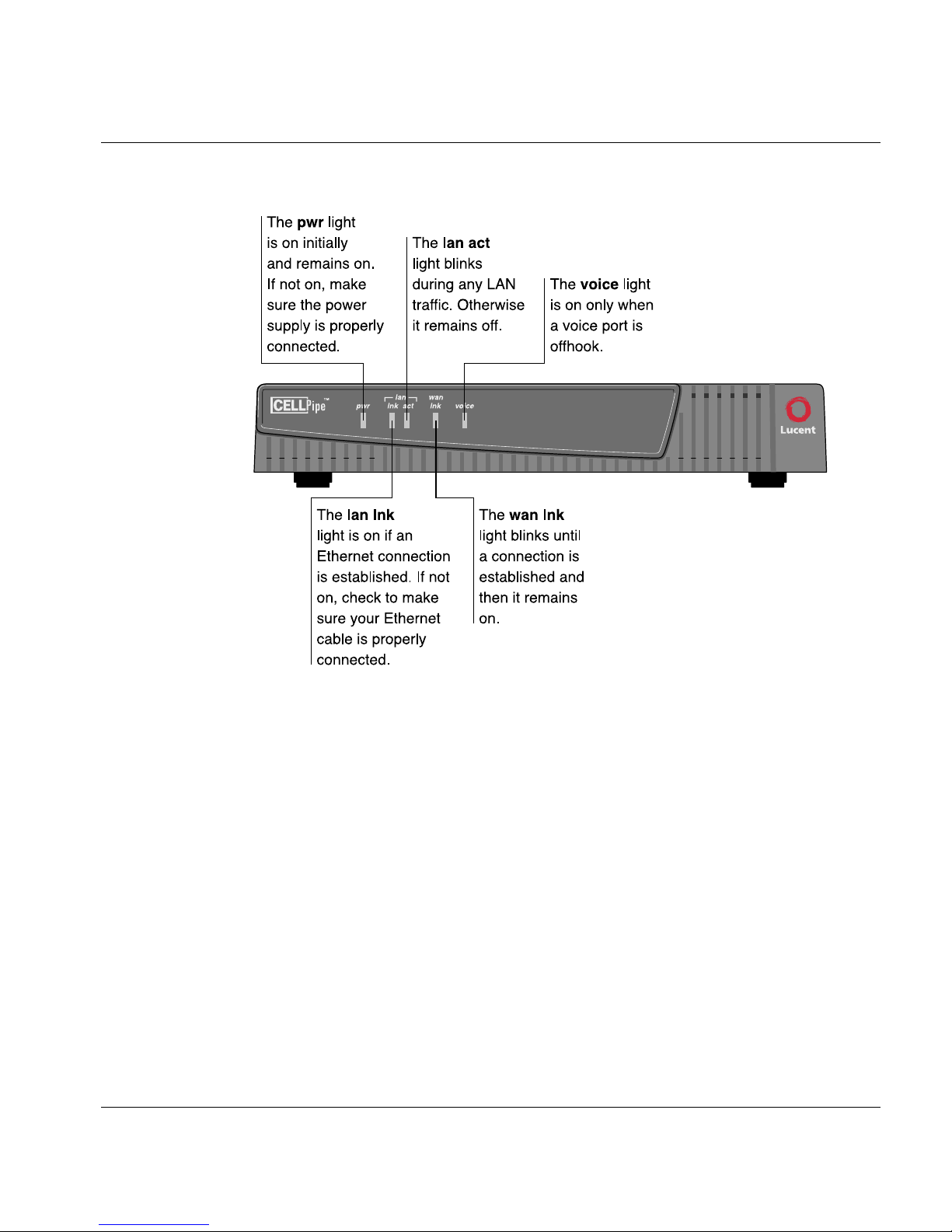
When all the cables are connected, verify the following status light behavior takes
place:
• The pwr light is on initially and remains on. If not on, make sure the power
supply is properly connected.
• The lan lnk light is on if an Ethernet connection is established. If not on,
check to make sure your Ethernet cable is properly connected.
• The lan act light blinks during any LAN traffic. Otherwise, it remains off.
• The wan lnk light blinks until a connection is established, and then it remains
on.
• The voice light is on only when a voice port is offhook.
CellPipe IAD 4A and CellPipe IAD 8T Hardware Installation Gu ide 11

CellPipe IAD 8T
Configuring a CellPipe IAD 8T unit
Configuring a Ce llPipe IAD 8T unit
!
Caution: If you attempt to manually configure the unit, a Delete Management Port
message appears. The unit disables Lucent TURN-UP to enable you to manually
configure the unit.
The Main menu items for the CellPipe IAD 8T unit are similar to those of other IAD
CellPipe units. Refer to the CellPipe™ IAD User’s Guide for a discussion of the Main
menu items. The menu exception for the CellPipe IAD 8T can be found in its
Configure WAN menu.
To configure the WAN interface on the CellPipe IAD 8T unit, proceed as follows:
1 Select Configure WAN from the Main Menu.
2 Select Configure Physical Interface under the WAN Configuration
menu.
3 Set the desired frame mode.
4 Proceed with the remaining configurations. See Table 2.
Table 2. T1 Configuration menu
Menu opti on Description
Select Frame Mode Choose between ESF (T1) Fram e Mode
or D4 Frame Mode.
12 CellPipe IAD 4A and CellPipe IAD 8T Hardware Installation Guide

Configuring a CellPipe IAD 8T unit
Table 2. T1 Configuration menu (continued)
Menu opti on Description
Select Line Build Displays the Select Line Build Out
submenu, which contains the following
commands that set compensation for
signal or line loss during the T1
connection. Check with your service
provider for the appropriate signal loss
(dB).
– 1. 0 to 133 Feet (0 dB)
– 2. 133 to 266 Feet
– 3. 266 to 399 Feet
– 4. 399 to 533 Feet
CellPipe IAD 8T
– 5. 533 to 655 Feet
– 6.0 – 7.5 dB
– 7.0 – 15 dB
– 8. 0 – 22.5 dB
Enable/Disable B8ZS Enables and disables bipolar 8-zero
substitution (B8ZS) line code.
Configure Transmit Channels Allows you to set the number of
transmission channels (maximum 24)
for the WAN interface.
Configure Receive Channels Allows you to set the nu mber o f receive
channels (maximum 24) for the WAN
interface.
Configure Clock Source Choose the Internal or External Clock
Source.
Change to E1 Mode Currently not supported.
CellPipe IAD 4A and CellPipe IAD 8T Hardware Installation Gu ide 13


Connector Pinouts
TERMINAL pinouts
Pin Signal
1GND
2Tx Data
3Rx Data
10/100 LAN connector pinouts
Pin Signal
1Tx
2Tx
3Rx
4NC
5NC
6Rx
7NC
8NC
CellPipe IAD 4A and CellPipe IAD 8T Hardware Installatio n Guid e 15

Connector Pinouts
T1 Connector pinouts
T1 Connector pinouts
Pin Signal
1 Rx Ring
2Rx Tip
3NC
4Tx Tip
5Tx Ring
6NC
7NC
8NC
ADSL connector pinouts
Pin Signal
1NC
2NC
3Tip
4Ring
5NC
6NC
16 CellPipe IAD 4A and CellPipe IAD 8T Hardware Installation Guide

FCC Regulations
FCC Part 15 Notice . . . . . . . . . . . . . . . . . . . . . . . . . . . . . . . . . . . . . . . . . . . . 17
IC CS-03 Notice. . . . . . . . . . . . . . . . . . . . . . . . . . . . . . . . . . . . . . . . . . . . . . . 18
FCC Part 15 Notice
!
Warning: This equipment has been tested and found to comply with the limits
for a Class B digital device, pursuant to Part 15 of the FCC rules. These limits are
designed to provide reasonable protection against harmful interference when the
equipment is operated in a residential environment. This equipment generates,
uses, and can radiate radio frequency energy, and, if not installed and used in
accordance with the instruction manual, may cause harmful interference to radio
communications. Operation of this equipment in a residential area is unlikely to
cause harmful interference. But if it does, the user will be required to correct the
interference at his or her own expense.
The authority to operate this equipmen t is conditioned b y the requiremen t that no
modifications will be made to the equipment unless the changes or modifications
are expressly approved by Lucent Technologies.
CellPipe IAD 4A and CellPipe IAD 8T Hardware Installatio n Guid e 17

FCC Regulations
IC CS-03 Notice
IC CS-03 Notice
The Industry Canada label identifies certified equipment. This certification
means that the equipment meets certain telecommunications network protective,
operational, and safety requirements as prescribed in the appropriate Terminal
Equipment Technical Requirements document(s). The Department does not
guarantee that the equipment will operate to the user’s satisfaction.
Before installing this equipment, users should make sure that it is permissible to
be connected to the facilities of the local telecommunications company. An
acceptable method of connection must be used to install the equipment. The
customer should be aware that compliance with the above conditions may not
prevent degradation of service in some situations.
Repairs to certified equipment should be coordinated by a representative
designated by the supplier. Any repairs or alterations made by the user to this
equipment, or equipment malfunctions, may give the telecommunications
company cause to request the user to disconnect the equipment.
Users should ensure for their own protection that the electrical ground
connections of the power utility , telephone lines, and internal metallic water pipe
system, if present, are connected together. This precaution may be particularly
important in rural areas.
Warning: Users should not attempt to make such connectio ns themselves, but
should contact the appropriate electric inspection authority, or electrician, as
appropriate.
18 CellPipe IAD 4A and CellPipe IAD 8T Hardware Installation Guide
 Loading...