


CellPipe® 22A-GX
ADSL Ethernet Router
User Manual
Revision 1
February 2003

CellPipeTM 22A-GX ADSL Ethernet Router User Manual
Copyright © 2002 , 2 003 Lucen t Tec hnol o gies In c. A ll r i ghts r eser ve d.
This material is protected by the copyright laws of the United States and other countries. It may not be
reproduced, di strib uted, o r alte red in a ny fashion by any en tity (ei th er in te rnal o r e xternal to Lucent
Technologies), except in accordance with applicable agreements, contracts, or licensing, without the
express written consent o f Lucent Technolo gies. Fo r permission to reproduce or distribute , plea se
email your request to techcomm@lucent.com
.
Notice
Every effort was made to ensure that the infor mation in thi s docu ment was comple te and a ccurate at
the time of printing, but information is subject to change.
European Community (EC) RTTE Compliance
Hereby, Lucent Technologies, declares that the equipment documented in this publication is
in compliance with the essential requirements and other relevant provisions of the Radio and
Telecommunications Technical Equipment (RTTE) Directive 1999/5/EC.
To view the offici al Decl aratio n o f Co nfo r mity certi fic ate for this equipment, according t o E N 450 14 ,
access the Lucent INS online documentation library at http://www.lucentdocs.com/ins.
Industry Canada Self-Marking/Declaration of Conformity
The abbreviation, I C, b e fore t he regi stra tion n umber signifi e s th at regi stra tion wa s pe rformed ba sed
on a Declaration of Conformity indicating that Industry Canada technical specifications were met. It
does not imply th at In du stry Cana da ap proved t he eq uipmen t .
To view the offici al Decl aratio n o f Co nfo r mity certi ficate for this equip ment, access the Lucen t INS
online documentation library at http://www.lucentdocs.com/ins.
Safety, Complia nce, and Wa rranty In forma tion
Before handling any Lucent Access Netwo rks ha rdwa re p rodu ct, read the Edg e A ccess Saf ety an d
Compliance Guide, whi ch can be foun d at ht tp :/ /w ww.lu ce ntdo c s.co m/in s. Se e tha t gui de al so t o
determine how products comply with the electromagnetic interference (EMI) and network compatibility
requirements of y ou r coun try. Se e the wa r ranty ca rd i n cluded in your product package fo r t he li mi ted
warranty that Lu cent Technolo gie s p rovi de s for i t s produ cts.
Security Statement
In rare instances, unautho rized indivi duals make conne ction s to the teleco mmunications netw ork
through the use of access features.
Trademarks
Lucent, the Lu cent lo go, a nd all Lu cent b ra nd an d pr odu ct n a mes a re t r ade marks o r re gi ste red
trademarks of Lucent Technol ogi es Inc. Othe r brand and p roduct names a re trademarks of t heir
respective holders.
Ordering Informati o n
You can order the most up-to-dat e product in formation and compute r-based training online at
http://www.lucentdocs.com/ins.
Feedback
Lucent Technologie s appreciate s customer comments abo ut thi s manual. Plea se send them to
techcomm@lucent.com
.
Caution
To reduce the risk of fire, use only Number 26 AWG or larger telecommunications line cord.
Instruction provid ed in In stalla tio n In stru ction.
2

CellPipeTM 22A-GX ADSL Ethernet Router User Manual
Customer Service
Product and service information, and software upgrades, are available 24 hours a day. Technical
assistance option s a ccommo dat e v a ry ing lev el s o f u rgency.
Finding information and s oftware
To obtain softw a re u pg rad es, relea se no tes, and ad den da fo r this product, log in to L uce nt OnLi ne
Customer Support at http://www.lucent.com/support.
Lucent OnLine Customer Support also provides technical information, product information, and
descriptions of available services. The center is open 24hours a day, seven days a week. Log in and
select a servi ce .
Obtaining technical assistance
Lucent OnLine Customer Support at http://www.lucent.com/support provides access to technical
support. You can o bt ain te chni cal a ssi stan ce t h rough e mail o r the In te rnet , o r by t elephone . I f y ou
need assistance, make sure tha t you have the fol lowing informati on available :
• Product name, model, and serial number
• Software version
• Software and hardware option s. If supplie d by your carri er, servi ce pro file identi fiers (SP IDs)
associated with y our lin e
• Active service or maintenance contract number, entitlement ID, or site ID
• Your local telep hone company ’s swit ch ty pe an d o pe rating mode , such as A T& T 5ESS Cu sto m
or Northern Telecom Nati onal ISD N-1
• Whether you a re rout ing o r br id ging wi th your Lucent product
• Type of computer you are using
• Description of the problem
Obtaining assi stance through em ail o r the Inte rnet
If your servi ces ag r eement allows, you can communi cate di r e ctly w ith a te chni cal engin ee r th ro ugh
Email Technical Support or a Live Chat. Sele ct one of these sites when you log in to
http://www.lucent.com/support.
Calling the technical assistance center (TAC)
If you cannot find an a n swer t h rough th e tool s a nd in fo r mation o f Lu cent OnLi ne Custo mer S upp o rt o r
if you have a very urgent need, conta ct TAC. Ac cess Lucent OnLine Cu stomer Suppo rt at
http://www.lucent.com/support and click Contact Us for a list of telephone numbers inside and outside
the United States.
Alternatively , call 1-866-L UCEN T8 (1-866-5 82-3688 ) from any locati on in Nor th Ameri ca for a menu of
Lucent services. Or call +1 510 -769-600 1 for an operat or. If you do not have an active servi ces
agreement or cont ract, y ou w ill be charg ed for t i me an d mate ri al s.
3

CellPipeTM 22A-GX ADSL Ethernet Router User Manual
4

CellPipeTM 22A-GX ADSL Ethernet Router User Manual
Table of Contents
Customer Service................................................................. 3
Finding information and software...................3
Obtaining technical assistance........................3
Obtaining assistance through email or the
Internet .........................................................................3
Calling the technical assistance center (TAC)..............3
1 Introduction........................................................11
Features................................................................................11
System Requirements .........................................................11
Using this Document............................................................12
Notational convention s.................................................12
Typographical conventions ..........................................12
Special messages.........................................................12
2 Getting to Know the CellPipe 22A-GX.............. 13
Parts Check..........................................................................13
Front Panel...........................................................................13
Rear Panel............................................................................13
3 Quick Start.........................................................15
Part 1 — Connecting the Hardware....................................15
Step 1. Conne ct t he ADSL cable an d o pti onal
telephone. ..................................................................15
Step 2. Connect the Ethernet cable.............................16
Step 3. Attach the power connector. ...........................16
Step 4. Turn on the CellPipe 22A-GX and
power up your systems.............................................16
5
Step 5: Install USB software and conn e ct the
USB cable..................................................................16
Part 2 — Configuring Your Computers ..............................17
Before you begin...........................................................17
Windows® XP PCs:......................................................17

CellPipeTM 22A-GX ADSL Ethernet Router User Manual
Windows 2000 PCs:.....................................................18
Windows Me PCs .........................................................19
Windows 95, 98 PCs:...................................................20
Windows NT 4.0 workstations: ....................................21
Assigning static Inte rnet info rmati on to your
PCs.............................................................................22
Configuring a computer connected to the USB
port..............................................................................23
Part 3 — Configuring the CellPipe 22A-GX .......................28
Logging in to t he Cel lPip e 2 2A -GX Qui ck
Configuration Page ...................................................28
Default Router Settings ................................................31
Testing Your Setup ..............................................................32
4 Getting Started with the Configuration
Manager.......................................................... 33
Accessing the Configuration Manager ...............................33
Functional Layout.................................................................35
Commonly used buttons ..............................................35
The Home Page and System View Table..........................36
Changing System Information.............................................38
Changing System Information.............................................38
Changing Your Login Password.........................................39
Committing Your C hange s an d Reb ooting t he
Device................................................................................40
Committing your changes ............................................40
Rebooting the devi ce u si ng C on figur ati on
Manager.....................................................................41
5 Configuring the LAN and USB Ports ................43
Connecting via Eth e rne t and/o r USB.................................43
Configuring the LAN Port IP Address.................................44
6
Configuring the USB Port IP Address ................................47
6 Viewing System IP Addresses and IP
Performance Statistics ................................... 49

CellPipeTM 22A-GX ADSL Ethernet Router User Manual
Viewing the CellPipe 22A-GX devi ce’s IP
Addresses .........................................................................49
Viewing IP Performance Statistics......................................50
7 Configuring Dynamic Host Configuration
Protocol........................................................... 51
Overview of DHCP...............................................................51
What is DHCP?.............................................................51
Why use DHCP?...........................................................51
CellPipe 22A-GX DHCP modes ..................................52
Configuring DHCP Server ...................................................53
Guidelines for creating DHCP serve r addres s
pools...........................................................................53
Adding DHCP Server Address Pools..........................54
Viewing, modifying , a nd del eting ad d res s
pools...........................................................................57
Excluding IP addresses fro m a pool............................57
Viewing current DHCP address assignments ............58
Configuring DHCP Relay.....................................................59
Setting the DHCP Mode ......................................................60
8 Configuring Network Address Translation........ 61
Overview of NAT..................................................................61
Viewing NAT Global Settings and Statistics ......................63
Viewing NAT Rules and Rule Statistics..............................65
Viewing Current NAT Translations .....................................66
Adding NAT Rules ...............................................................68
The NAPT rule: Translating between private
and public IP addresses............................................68
The RDR rule: Allowing external access to a
LAN computer............................................................70
The Basic rule: Performing 1:1 translations ................72
The Filter rule: Configuring a BASIC rule with
additional criteria........................................................73
7
The Bimap rule: Performing two-way
translations.................................................................75
The Pass rule: Allowing specific addresses to
pass through untranslated........................................76

CellPipeTM 22A-GX ADSL Ethernet Router User Manual
9 Configuring DNS Server Addresses.................77
About DNS............................................................................77
Assigning DNS Addresses..................................................77
Configuring DNS Relay .......................................................78
10 Configuring IP Routes....................................... 81
Overview of IP Routes.........................................................81
IP routing versus telephone switching.........................81
Hops and gateways......................................................82
Using IP routes to define default gateways.................82
Do I need to define IP routes? .....................................82
Viewing the IP Routing Table..............................................83
Adding IP Routes.................................................................85
11 Configuring the Routing Information
Protocol........................................................... 87
RIP Overview .......................................................................87
When should you configure RIP?................................87
Configuring the device’s interfaces with RIP......................88
Viewing RIP Statistics..........................................................90
12 Configuring the ATM Virtual Circuit .................. 91
Viewing Your ATM VC.........................................................91
Adding ATM VCs .................................................................92
Modifying ATM VCs.............................................................94
13 Configuring PPP Interfaces............................... 95
8
Viewing Your Current PPP Configuration ..........................95
Viewing PPP Interface Details ............................................98
Adding a PPP Interface Definition ....................................100
Modifying and Deleting PPP Interfaces............................101

CellPipeTM 22A-GX ADSL Ethernet Router User Manual
14 Configuring EOA Interfaces............................ 103
Overview of EOA................................................................103
Viewing Your EOA Setup ..................................................104
Adding EOA Interfaces......................................................106
15 Configuring IPoA Interfaces............................109
Viewing Your IPoA Interface Setup ..................................109
Adding IPoA Interfaces......................................................111
16 Configuring Bridging........................................ 113
Overview of Bridges...........................................................113
Using the Bridging Feature................................................114
Defining Bridge Interfaces.................................................115
Deleting a Bridge Interface................................................116
17 Configuring Firewall Settings ..........................117
Configuring Global Firewall Settings.................................117
Managing the Black List ....................................................120
18 Configuring IP Filters and Blocking
Protocols.......................................................121
Configuring IP Filters .........................................................122
Viewing your IP filter configuration ............................122
Configuring IP filte r gl obal settin g s............................123
Creating IP filter rules .................................................124
IP filter rule examples .................................................129
Viewing IP filter statistics ............................................131
Managing current IP filter sessions............................131
9
Blocking Protocols..............................................................133
19 Viewing DSL Line Information ........................ 135

CellPipeTM 22A-GX ADSL Ethernet Router User Manual
20 Administrative Tasks....................................... 139
Viewing System Alarms.....................................................140
Viewing the Alarm Table ............................................140
Upgrading the Software.....................................................141
Using Diagnostics ..............................................................142
Modifying Port Settings......................................................143
Overview of IP port numbers .....................................143
Modifying the CellPipe 22A -GX device’ s port
numbers...................................................................143
A IP Addresses, Network Masks, and
Subnets.........................................................145
IP Addresses ......................................................................145
Structure of an IP address..........................................145
Network classes..........................................................146
Subnet masks.....................................................................146
B Binary Numbers............................................... 149
Binary Numbers .................................................................149
Bits and bytes..............................................................149
C Troubleshooting............................................... 151
Diagnosing Problem using IP Utilities...............................153
ping ..............................................................................153
nslookup ......................................................................154
D Glossary........................................................... 155
10

1 Introduction
Congratulations on b e coming t he owne r o f the Cell Pipe 22A - GX
ADSL Ethernet bridge/router. Your LAN (local area network) will
now be able to a c cess t he Int e rnet u sing your high-speed ADSL
connection.
This User Manual w ill show y ou h ow to set up th e CellP ip e 2 2A -GX
and how to customize its configu rati on to get the most out of your
new product.
Features
! Internal ADSL modem for high-speed Internet access
! 10/100Base-T Ethernet router to provide Internet
connectivity to all computers on you r LAN
! U SB p ort for conne ctin g a USB -enabl ed PC
! N etwor k address tran slation (NAT), Fi rewall, and IP filte ring
functions to provide security for y our LAN
! N etw o rk con figu r ati on th rough D HCP Se rve r a nd DH CP
Relay
! Services including IP route and DNS configuration, RIP,
and IP and DSL performan ce monito ring
! C onfigu rati on p rogr a m you access via an H TML brow se r
System Requirements
In order to use the CellPipe 22A-GX router, you must have the
following:
! A DSL servi ce up and runni ng on you r telephone line , with
at least one public Internet address for your LAN
! One or more computers each containing an Ethernet
10Base-T/100Base-T ne twork inte rface card (NIC ) and/or a
single computer with a USB port
! An Et he rnet hu b/swit ch, i f y ou a re conne cting t he devi ce to
more than one compute r on an Ethernet netwo rk
! For system configuration using the supplied web-based
program: a web b row se r such a s In te r net Explorer v5.0 or
later, or Net scape v 4 .7 o r l ate r
11

Chapter 1. Introduction CellPipeTM 22A-GX ADSL Ethernet Router User Manual
Using this Document
Notational conventions
! A crony ms are define d the first ti me they appear in text and
in the glossary (Appen di x D).
! Fo r b revity , t he Cell Pipe 22 A-GX i s so meti mes refe rred to
as the “device. ”
! The terms LAN and netwo r k a re u s ed int er change ably to
refer to a group of Etherne t-conne cted co mputer s at one
site.
Typographical conventions
! Italics are used to id en ti fy t e rms th at a re d e fined in t he
glossary (Appendi x D ).
! Bolded text is used for items you select from menus and
drop-down list s, an d text string s y ou ty pe w hen p ro mpted
by the progra m.
Special messages
This document u ses t he fol low ing i con s to call your attention to
specific instructions or explanations.
Note
Definition
WARNING
Provides clarifying or non-essential information on the current
topic.
Explains terms or acronyms that may be unfamiliar to many
readers. The se te rms a re also included in the Glo ssar y.
Provides messages of high importance, including messages
relating to personal safe t y or syst em in teg ri t y.
12

2 Getting to Know the CellPipe 22A-GX
Parts Check
In addition to th i s do cument , y ou r CellPi pe 22A -G X should a rrive
with the following:
! C ellPi pe 22A -G X ADSL E ther net B ridge/ Ro ute r
! Pow e r ad apt e r and pow e r cord
! U SB cable
! E thernet cable (“st raight-th rough” ty pe)
! S tan da rd ph one /DS L line cable
Front Panel
The front panel contain s lights called LED s that indi cate the stat us
of the unit.
Label Color Function
PWR green On: Unit is powered on
Off: Unit is powered off
ALM red On: Fault
Off: Normal operation
LAN green On: LAN link established and active
Off: No LAN link
Blink: Activity
USB green On: USB link is established
Off: No USB link
WAN green On: ADSL link established and active
Blink: No ADSL link (slow) or training (fast)
Rear Panel
The rear panel contai n s the p o rt s for t he uni t ' s dat a a nd p ow er
connections.
Label Function
13
WAN Connects the device to a telephone jack for DSL
communication
USB Connects to the USB port on your PC
Ethernet Connects the device to your PC's Ethernet port, or to
the uplink port on your LAN's hub, using the cable
provided

Chapter 2. Getting to Know the CellPipe 22A-GX CellPipeTM 22A-GX ADSL Ethernet Router User Manual
Label Function
PWR Connects to the supplied power converter cable
Console Serial port connection
14

3 Quick S t art
This Quick Start provides basic instructions for connecting the
CellPipe 22A-GX to a compute r or LAN and to the Internet .
! Part 1 describes setting up the hardware.
! Part 2 describes how to configure Internet properties on
your computer(s) and how to in stall the so ftware fo r using a
computer attached to the USB port.
! Part 3 shows you how to configure basic settings on the
CellPipe 22A-GX to g et y our LA N conn ecte d to th e
Internet.
After setting up and co nfigu ring the dev ice, you ca n follow th e
instructions on p age 3 2 to v erify that it i s wo rking p r ope rly.
This Quick Start assumes tha t you have alr eady establ ish ed ADSL
service with your Internet service provider (ISP). These instructions
provide a basic configuration that should be compatible with your
home or small office network setup. Refer to the subsequent
chapters for additional configurati on inst ruction s.
Part 1 — Connecting the Hardware
In Part 1, you conne ct th e d evi ce t o the p hon e ja ck, th e powe r
outlet, and your computer or network.
Before you be gi n, t urn t he powe r of f for all dev ice s. These
include your computer(s), your LAN hub/switch (if applicable),
WARNING
WARNING
and the CellPipe 22A-GX.
Step 1. Connect the ADSL cable and optional telephone.
Connect one end o f the provid ed ph one cable to th e po rt la bel ed
ADSL on the rea r pan el o f the dev i ce. C onn e ct t he ot he r end to
your wall phone jack.
You can attach a t elep hon e lin e to th e devi ce . Thi s i s he lpfu l wh en
the ADSL line u ses t he only convenient wall ph one jack. If d e sired ,
connect the telephone cable to the port labeled PHONE.
Although you us e the sam e typ e o f cabl e, th e A DSL an d P HONE
ports are not interchangeable. Do not route the ADSL conne ction
through the PHONE port.
15

Chapter 3. Quick Start CellPipeTM 22A-GX ADSL Ethernet Router User Manual
Step 2. Connec t the Et herne t cable.
If you are con nec ting a LAN to the CellPipe 22A -GX device , at ta ch
one end of a provided Ethernet cable to a regul ar hub port and the
other to the Et hern et por t on the Ce llPip e 2 2A -GX.
If you are using the CellPipe 22A-GX with a single computer and no
hub, you must use a “ crossover ” Et he rnet cabl e (not p rovided ) to
attach the PC directly to the devi ce. The crossove r cable is wired
differently than the cable you would use to connect to a hub. When
you compare the colored wires on each end of a straig ht-th rough
cable, they will be in the same sequence; on crossove r cables, they
will not. Conta ct y our ISP fo r as sista n ce.
Step 3. Attach the power connector.
Connect the AC power adapt er to the PWR conne ctor on the bac k
of the device an d p lug in th e a dap te r to a wall out let o r pow e r st rip .
Step 4. Turn on the CellPipe 22A-GX and power up your
systems.
Press the Power switch on the back pan el of the device to the ON
position.
Turn on and boo t up your computer(s) and any LAN d evice s such
as hubs or switches.
Step 5: Instal l U SB sof tware and con nec t t he USB c abl e.
You can attach a single computer to the devi ce using a USB cable.
The USB port i s u seful i f y ou have a USB -ena bled PC tha t does no t
have a network interfa ce card fo r attaching to your Ethe rnet
network.
Before attaching the US B cable, y ou must in stall a USB drive r and
configure the computer. For complete inst ructions , see page 23.
16

CellPipeTM 22A-GX ADSL Ethernet Router User Manual Chapter 3. Quick Start
Part 2 — Configuring Your Computers
Part 2 of the Quick Start provides instructions for configuring the
Internet settings on your computers to work with the CellPipe 22AGX.
Before you begin
By default, the C ellPipe 22A -GX au to mati cally a s signs all r equired
Internet settings to your PCs. You need only to configure the PCs to
accept the infor mation w he n i t i s a s signe d.
In some cases, you may want to assign Internet information
manually to some or all of your compute rs rather than allow the
Note
CellPipe 22A-GX to do so. See “Assignin g stati c Interne t inform ation
to your PCs” on page 22 fo r inst ruction s .
! I f you have connected y ou r P C vi a the USB po rt, see the
USB configuration instructions on page 23.
! I f you have connected y ou r P C of LAN via Et hern et to the
CellPipe 22A-GX, follow the inst ructions tha t correspon d to
the operating system installed on your PC.
Windows® XP PCs:
1. In the Windows task bar, click the Start button, and then click
Control Panel.
2. Double-click the Network Connections icon.
3. In the LAN or High-Speed Internet window, right-click on the
icon corresponding to your network interface card (NIC) and
select Properties. (Often, this icon is labeled Local Area
Connection).
The Local Area Co nne ctio n di alo g b o x di splay s w ith a li st o f
currently installed network items.
4. Ensure that the check box to the left of the item labeled
Internet Protocol TCP/IP is checked, and click
.
5. In the Internet Protocol (TCP/IP) Properties dialog box, click
the radio button labeled Obtain an IP address
automatically. Also click the radio button labeled Obtain
DNS server address automatically.
6. Click
twice to confirm your changes, and close
the Control Panel.
17

Chapter 3. Quick Start CellPipeTM 22A-GX ADSL Ethernet Router User Manual
Windows 2000 PCs:
First, check for the IP protocol and, if necessary, install it:
1. In the Windows task bar, click the Start button, point to
Settings, and then click Control Panel.
2. Double-click the Network and Dial-up Connections icon.
3. In the Network and Dial-up Connections window, right-click
the Local Area Connection icon, and the n selec t Properties.
The Local Area Co nne ctio n P ro pe rtie s dialog box displays wi th
a list of currently installed network co mponent s. I f th e li st
includes Internet P r oto col ( TCP/ IP ), th en th e prot o col has
already been en able d. S kip to step 10 .
4. If Internet Protocol (TCP/IP) does not display as an installed
component, click
.
5. In the Select Network Component Type dialog box, select
Protocol, and then click
.
6. Select Internet Protocol (TCP/IP) in the Network Protocols
list, and then click
.
You may be prompted to install files from your Windows 2000
installation CD or o ther media . Follow the in st ruction s to in stall
the files.
7. If prompted, click
to restart your computer with
the new settings.
Next, configure the PCs t o acce pt IP in fo rmation assigned by th e
CellPipe 22A-GX:
8. In the Control Panel, double-click the Network and Dial-up
Connections icon.
9. In Network and Dial-up Connections window, right-click the
Local Area Connection icon, and then select Properties.
10. In the Local Area Connection Properties dialog box, select
Internet Protocol (TCP/IP), and then click
.
18
11. In the Internet Protocol (TCP/IP) Properties dialog box, click
the radio button labeled Obtain an IP address
automatically. Also click the radio button labeled Obtain
DNS server address automatically.
12. Click
twice to confirm and save your changes,
and then close the Control Panel.

CellPipeTM 22A-GX ADSL Ethernet Router User Manual Chapter 3. Quick Start
Windows Me PCs
1. In the Windows task bar, click the Start button, point to
Settings, and then click Control Panel.
2. Double-click the Network and Dial-up Connections icon.
3. In the Network and Dial-up Connections window, right-click
the Network icon, and then select Properties.
The Network Properties dialog box displays with a list of
currently installed ne tw or k compo nen t s. If the li st i n clud es
Internet Proto col (TC P/ IP ), th en th e p roto col ha s al re ady bee n
enabled. Skip to step 11.
4. If Internet Protocol (TCP/IP) does not display as an installed
component, click
.
5. In the Select Network Component Type dialog box, select
Protocol, and then click
.
6. Select Microsoft in the Manufacturers box.
7. Select Internet Protocol (TCP/IP) in the Network Protocols
list, and then click
.
You may be prompted to install files from your Windows Me
installation CD or o ther media . Follow the in st ruction s to in stall
the files.
8. If prompted, click
to restart your computer with
the new settings.
Next, configure the PCs t o acce pt IP in fo rmation assigned by th e
CellPipe 22A-GX:
9. In the Control Panel, double-click the Network and Dial-up
Connections icon.
10. In Network and Dial-up Connections window, right-click the
Network icon, and then select Properties.
11. In the Network Properties dialog box, select TCP/IP, and
19
then click
.
12. In the TCP/IP Settings dialog box, click the radio button
labeled Server assigned IP address. Also click the radio
button labeled Server assigned name server address.
13. Click
twice to confirm and save your changes,
and then close the Control Panel.

Chapter 3. Quick Start CellPipeTM 22A-GX ADSL Ethernet Router User Manual
Windows 95, 98 PCs:
First, check for the IP protocol and, if necessary, install it:
1. In the Windows task bar, click the Start button, point to
Settings, and then click Control Panel.
2. Double-click the Network icon.
The Network dialog bo x di splay s with a li st o f cu rren tly in stalle d
network components. I f the list includ es TCP/IP, and then the
protocol has al ready been enabled. Skip t o step 9 .
3. If TCP/IP does not display as an installed component, click
.
The Select Netw or k Co mpon ent Ty pe di alog b o x di splays.
4. Select Protocol, and then click
.
The Select Netwo rk Pr oto col dial og bo x di splay s.
5. Click on Microsoft in the Manufacturers list box, and then
click TCP/IP in the Network Protocols list box.
6. Click
then click
to return to the Network dialog box, and
again.
You may be prompted to install files from your Windows 95/98
installation CD. Follow th e i nst ru ction s to install the files.
7. Click
to restart the PC and complete the
TCP/IP installation.
Next, configure the PCs t o acce pt IP in fo rmation assigned by th e
CellPipe 22A-GX:
8. Open the Control Panel window, and then click the Network
icon.
9. Select the network component labeled TCP/IP, and then
click
.
If you have multiple TCP/IP list ing s, sele ct the li sting associa te d
with your network card or adapter.
20
10. In the TCP/IP Properties dialog box, click the IP Address tab.
11. Click the radio button labeled Obtain an IP address
automatically.
12. Click the DNS Configuration tab, and then click the radio
button labeled Obtain an IP address automatically.
13. Click
twice to confirm and save your changes.
You will be prompted to restart Windows.
14. Click
.

CellPipeTM 22A-GX ADSL Ethernet Router User Manual Chapter 3. Quick Start
Window s NT 4.0 worksta ti o n s :
First, check for the IP protocol and, if necessary, install it:
1. In the Windows NT task bar, click the Start button, point to
Settings, and then click Control Panel.
2. In the Control Panel window, double click the Network icon.
3. In the Network dialog box, click the Protocols tab.
The Protocols tab display s a list of currently installed netw ork
protocols. If the list in clude s TCP/IP, then th e proto col has
already been en able d. S kip to step 9.
4. If TCP/IP does not display as an installed component, click
.
5. In the Select Network Protocol dialog box, select TCP/IP,
and then click
.
You may be prompted to install files from your Windows NT
installation CD or o ther media . Follow the in st ruction s to in stall
the files.
After all file s are in stall ed, a w ind ow di splay s to in fo r m y ou that
a TCP/IP service called DHCP can be set up to dynamical ly
assign IP info rmatio n.
6. Click
to continue, and then click if
prompted to restart your computer.
Next, configure the PCs t o acce pt IP in fo rmation assigned by th e
CellPipe 22A-GX:
7. Open the Control Panel window, and then double-click the
Network icon.
8. In the Network dialog box, click the Protocols tab.
9. In the Protocols tab, select TCP/IP, and then click
.
10. In the Microsoft TCP/IP Properties dialog box, click the radio
button labeled Obtain an IP address from a DHCP server.
11. Click
twice to confirm and save your changes,
and then close the Control Panel.
21

Chapter 3. Quick Start CellPipeTM 22A-GX ADSL Ethernet Router User Manual
Assigning s tatic Inte rnet informa tio n to you r PCs
In some cases, you may want to assign Internet information to
some or all of your PCs directly (often call ed “stati cally” ), rather than
allowing the Cell Pipe 22 A- GX to a ssi gn it. Thi s o pti on may be
desirable (but n ot r equ ired ) i f:
! Y ou have ob tai ned on e or mor e p ubli c IP a dd res ses t ha t
you want to always associate with specific computers (for
example, if y ou a re u sing a co mpute r a s a p ubli c w eb
server).
! Y ou maintai n diffe rent subnet s on your LAN (subnet s are
described in Appendi x A) .
Before you begi n, conta ct your ISP if you do no t a lr eady h ave th e
following information:
! The IP address and subnet mask to be assigned to each
PC to which you will be assigning static IP information.
! The IP address of the default gateway for your LAN. In
most cases, this is the address assigned to the LAN port on
the CellPipe 22A -GX. By default, the LAN po rt i s a ssig ned
this IP address: 192. 168 .1 .1. (Y ou can cha nge thi s number ,
or another number can be assigned by your ISP. See
Chapter 5 for more information.)
! The IP address of your ISP’s Domain Name System (DNS)
server.
On each PC to which y ou w a nt to a ssign stati c in fo r mation, follow
the instructions on pages 17 through 21 relating only to checking for
and/or installing the IP p rotocol . On ce it i s in stalle d, contin ue to
follow the instructions for displaying each of the Internet Protocol
(TCP/IP) properties. Instead of enabling dynamic assignment of the
IP addresses for the computer, DNS server, and default gateway,
click the radio buttons that enable you to ente r the infor mation
manually.
22
Note
Your PCs must have IP add resse s tha t pla ce t hem in t he sa me
subnet as the CellPipe 22A-GX’ s LAN port. If you manuall y assign
IP information to all your LAN PCs, you can follow the instructions in
Chapter 5 to change the LAN port IP address accordingly.

CellPipeTM 22A-GX ADSL Ethernet Router User Manual Chapter 3. Quick Start
Configurin g a comp uter con necte d to the USB port
If you use the CellPipe 22A-GX’s USB port to connect to a PC, you
must install the provided USB driver software on the PC. The driver
enables Etherne t-ove r-US B co mmun i cation w ith t he CellPi pe 22A GX.
Configuring the USB computer is a two-part process:
! In Part 1, you install the USB driver on the PC.
! In Part 2, you configure the IP properties on the USB PC.
Part 1. Installing the USB Driver:
1. Ensure that the USB cable is not connected to the USB
port on the PC or to the USB port on the CELLPIPE 22A-GX
device. The installation program will prompt you when to
connect the cable.
2. Copy the USB installation files to a temporary directory on
the USB computer.
3. In the folder where you copied the files, double-click on
setup.exe to start the installation program.
The Welcome dialog bo x di splay s, a s shown in Fi gu re 1 :
Figure 1. USB Driver Installation: Welcome Screen
23

Chapter 3. Quick Start CellPipeTM 22A-GX ADSL Ethernet Router User Manual
4. Click to display the Software License
Agreement dialog box, as shown in Figure 2.
Figure 2. USB Driver Installation: Software License Agreement
5. After reviewing the license agreement, click
continue.
6. If a Microsoft digital signature dialog box displays, click
to continue.
The installation p rogr am will b egin copy ing t he ne cessa ry
installation files to the r equired lo cations. When finished, the
Setup Complete dialog box will display , as shown in Figure 3.
to
24
Figure 3. USB Driver Installation: Setup Complete

CellPipeTM 22A-GX ADSL Ethernet Router User Manual Chapter 3. Quick Start
7. Click .
A DSL Installer dialog box displays while the program searches
for your USB hardware. Afte r a few second s, a second dial og
box displays to prompt you to attach the USB cable, as shown
in Figure 4.
Figure 4. USB Driver Installation: DSL Installer
8. Attach the USB cable to the CellPipe 22A-GX and to your
PC.
The USB cable p rovided ha s a fla t conn e ctor on o ne end
(called Type A) and a square connector on the other (Type B).
Connect the fla t conne ct or t o your PC and the squa re
connector to the CellPipe 22A-GX.
A window display s b ri e fly, i ndicating that the sy ste m h as fo un d
new hardware.
9. If a Microsoft digital signature dialog box displays, click
to continue.
The System Settings Change dialog box displays to prompt you
to restart your computer, a s shown in Figure 5:
Figure 5. USB Driver Installation: System Settings Change
25
Chapter 3. Quick Start CellPipeTM 22A-GX ADSL Ethernet Router User Manual
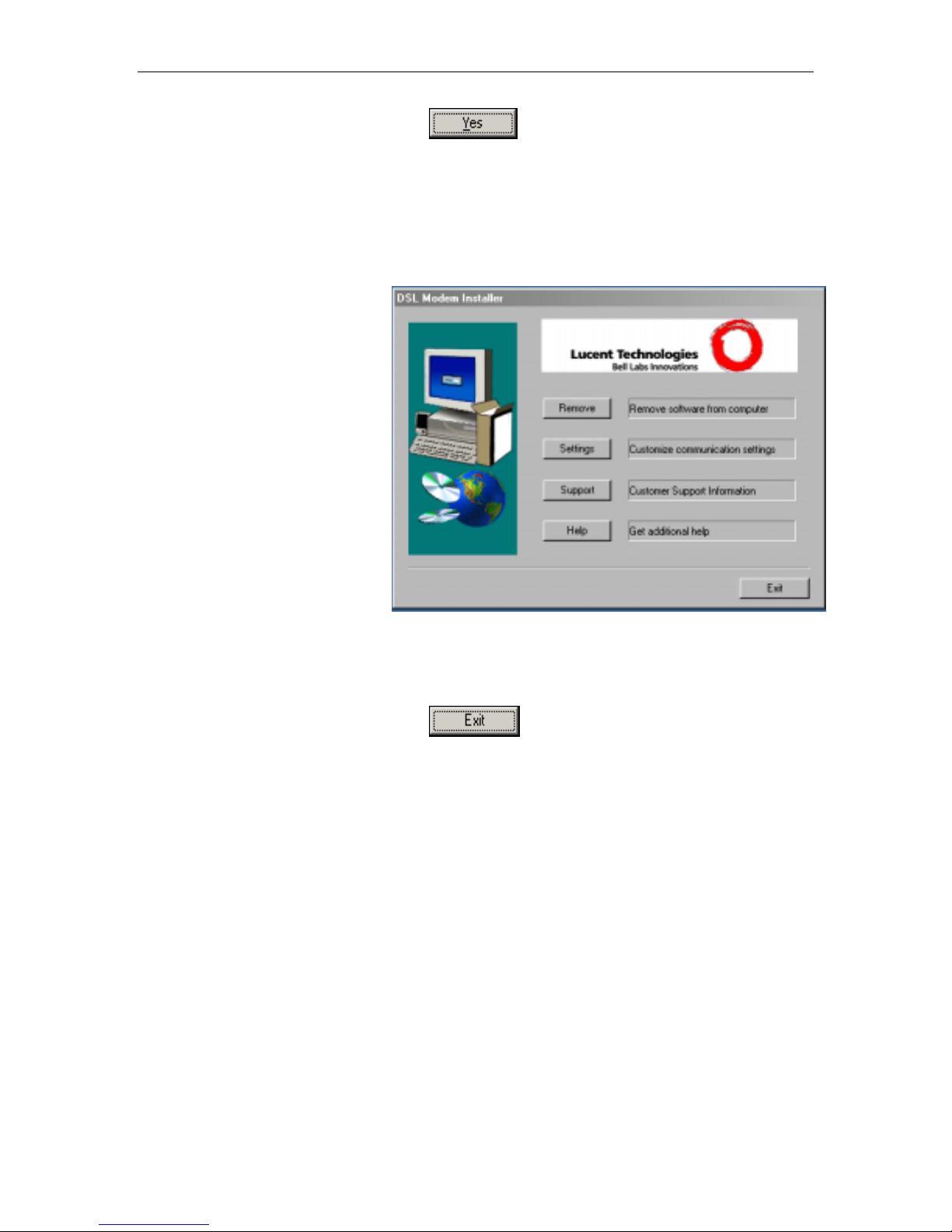
10. Click to restart your computer.
When your computer fini shes rebooti ng, make sure that the Lucent
installer program displays as an item on your Windows Start menu:
11. Click the Start button, point to Programs » Lucent DSL
Modem, and click on Configure.
The DSL Modem In stall er dial og bo x sho uld display, as shown
in Figure 6.
Figure 6. DSL Modem Installer Dialog Box
This step is o nly ve rifi cati on . Y ou do not n eed t o a cce ss th e
configuration program at this time.
12. Click
.
You are now finished installing the necessary drive r. Proceed to
Part 2 to configure IP properties on the USB PC.
26

CellPipeTM 22A-GX ADSL Ethernet Router User Manual Chapter 3. Quick Start
Part 2. Configuring IP properties on the USB PC. Now that the
USB driver installation is comple te, you must config ure the USB PC
so that its IP prope r ties pl a ce it on t he sa me subne t a s t he Cel lPipe
22A-GX’s USB port. There are two ways to do this:
! The CellPipe 22A -GX is configu red to assign an
appropriate IP address to the USB PC. If you wan t to use
this automatic assignment feature, called “DHCP server,”
you must configure the USB PC to accept dynamically
assigned IP information. Follow the instruction on pages 17
through 21 that corre spond to the operati ng syste m
installed on the PC .
! If you want to assign a static IP address to the PC, follow
the instructions on pa ge 22 an d u se the followi ng
information.
• In the Netw o r k and D ial -u p Co nnectio n s w ind ow , b e
sure to select the icon that corresponds to your new
USB connection (not the one that correspond s to your
Ethernet NIC). When you display the properties for the
icon, the follow ing t e xt should di splay in th e Con ne ct
Using text box:
Lucent USB IA D LA N M od em #n
• The USB port on the CellPipe 22A-GX is preconfigured
with these properties:
USB port IP address: 192.168.2.1
USB port subnet mask: 255.255.255.0
Therefore, your PC must be configured as follows:
IP address: 192.168.1.n where n is a
number from 2 to 254.
Subnet mask: 255.255.255.0
Default gatewa y: 192.168.2.1
27

Chapter 3. Quick Start CellPipeTM 22A-GX ADSL Ethernet Router User Manual
Part 3 — Configuring the CellPipe 22A -GX
In Part 3, you log into the progra m on the CellPi pe 22A-GX an d
configure basic settings for your Internet connection. Your ISP
should provide you with the necessary information to complete this
step.
Logging in t o th e Ce llP i pe 22 A -GX Q uick C on fi g u rat io n P a ge
The CellPipe 22A-GX provides a preinstalled software program
called Configuratio n M ana ger w hi c h enabl e s you to con figu re th e
operation of the device via your Web browser. The settings that you
are most likely t o nee d to cha nge befo re u sing th e devi ce a re
grouped onto a single Quic k Configu ration pag e.
Follow these inst ruction s configu re the devi ce set ting s:
1. At any PC connected to the CellPipe 22A-GX via Ethernet,
open your Web browser, and type the following URL in the
address/location box:
192.168.1.1/se tu p
When you press <Return>, the page shown in Figure 7 should
display (see Appendix C, “ Troubleshoo ting,” if you receive an
error message or th e pag e do e s not di splay ).
28
Figure 7. Quick Configuration Page in Configuration Manager

CellPipeTM 22A-GX ADSL Ethernet Router User Manual Chapter 3. Quick Start
The fields are described in the following table. Work with your ISP to
determine which settings you need to change.
Field Description
General Settings
ATM Interface
Operation
Mode
Encapsulation
VCI and VPI
Bridge
IGMP
IP Address
and Subnet
Mask
Default Route
Gateway IP
Address
PPP User
Name and
Password
Use DNS
Primary/
Secondary
DNS Server
Select the ATM interface you want to use (usually atm-0).
Your system may be configured with more than one ATM
interface if you are using different types of services with
your ISP.
This setting enables or disables the CellPipe 22A-GX.
When set to “No,” the device cannot be used to provide
Internet connectivity for your network. Set it to “Enabled”
now, if necessary.
This setting determines the type of data link your ISP uses
to communicate with your CellPipe 22A-GX. Contact them
to determine the appropriate setting.
These values are provided by your ISP and determine the
unique path your connection uses to communicate with
your ISP.
This setting enables or disables bridging between the
CellPipe 22A-GX and your ISP. Your ISPs may also refer
to this as “RFC 1483” or “Ethernet over ATM”.
This setting enables or disables the Internet Group
Management Protocol, which some ISPs use to perform
remote configuration of your device.
If your ISP has assigned a public IP address to your LAN,
enter the address and the associated subnet mask in the
boxes provided. (Note: in some configurations, the public
IP address should be entered on your PC rather than on
the CellPipe 22A-GX; check with your ISP.)
When enabled, this setting specifies that the IP address
specified above will be used as the default route for your
LAN. Whenever, one of your LAN computers attempts to
access the Internet, the data will be sent via the WAN
interface.
Specify the IP address that identifies the ISP server
through which your Internet connection will be routed.
PPP Settings
Enter the username and password you use to log in to
your ISP. (Note: this is not the same as the user name and
password you used to log in to Configuration Manager.)
Enable this feature if the DNS server addresses that your
LAN will use should be supplied dynamically each time
you connect to the ISP. If you click Disable, you must
configure DNS addresses manually on each PC or on the
fields below.
DNS Settings
Enter the Primary and Secondary Domain Name System
(DNS) server addresses provided by your ISP.
29

Chapter 3. Quick Start CellPipeTM 22A-GX ADSL Ethernet Router User Manual
2. When finished customizing these settings, click .
The settings are now in effect; however, if you reboot or if the
power is disconnected , y ou r settings will be lost. In step 3, y ou
save the changes to permanent memory:
3. Click the Admin tab that displays in the upper right of the
page, and then click Commit & Reboot in the task bar.
4. Click
.
A page will display b rie fly to co n firm y ou r chang e s, an d then
you will be ret u rned to th e Co mmi t & Reboot page.
You can click
to remove all existing Quick Configuration
settings and retu rn t o the d e fault v al ue s.
You are now finished customiz ing basic se tting s. Read the foll owing
section to determine i f you need to change addition al settin gs.
30

CellPipeTM 22A-GX ADSL Ethernet Router User Manual Chapter 3. Quick Start
Default Router Settings
In addition to handling the DSL connection to your ISP, th e CellPipe
22A-GX ADSL/Ethernet router can provide a variety of services to
your network. The device is preconfigured with default settings for
use with a typical home or small office network.
Table 1 lists some of the most important default settings; these and
other features a re de scri bed fu lly in the subsequent chapte r s. I f y ou
are familiar with netwo rk configu ration, review the set tings in Table
1 to verify that they meet the needs of your network. Follow the
instructions to change them if necessary. If you are unfamiliar with
these settings, try using the device without modification, or contact
your IS P fo r a ssi st an ce .
Before you modifying any settings, revi ew Chapt er 4 for gene ral
information about a ccessing a nd u sing the Con figu ratio n M ana ger
program. We strongly recommend that you contact your ISP prior to
changing the default co nfigu ration.
Table 1. Default Settings Summary
Option Default Setting Explanation/Instructions
DHCP (Dynamic
Host Configuration
Protocol)
NAT (Network
Address Translation)
LAN Port
IP Address
USB Port
IP Address
DHCP server enabled with the following
pool of addresses:
192.168.1.3 through 192.168.1.34
NAPT rule enabled Your computers’ private IP addresses (see
Static IP address: 192.168.1.1
subnet mask: 255.255.255.0
Assigned static IP address:
192.168.2.1
subnet mask: 255.255.255.0
The CellPipe 22A-GX maintains a pool of
private IP addresses for dynamic assignment to
your LAN computers. To use this service, you
must have set up your computers to accept IP
information dynamically, as described in Part 2
of the Quick Start. See Chapter 7 for an
explanation of the DHCP service.
DHCP above) will be translated to your public
IP address whenever they access the Internet.
See Chapter 1 for a description of the NAT
service.
This is the IP address of the LAN port on the
device. The LAN port connects the device to
your Ethernet network. Typically, you will not
need to change this address. See Chapter 5 for
instructions.
This is the IP address assigned to the USB port
on the device (if used). Typically, you will not
need to change this address. See Chapter 5 for
instructions.
31

Chapter 3. Quick Start CellPipeTM 22A-GX ADSL Ethernet Router User Manual
Testing Your Setup
The Quick Start process should enable any computer on your LAN
to use the CellPipe 22A-GX’s ADSL co nnection to a ccess the
Internet.
To test the co nnectio n, t urn o n the dev i ce, w ait a bou t 30 se conds,
and then veri fy t hat i t s LED s a r e il lu minat ed a s show n i n Tab le 2.
Table 2. LED Indicators
This LED : ...should be:
PWR
DIAG
USB
LINK LAN
LINK WAN
WAN ACT
Solid green to indicate that the device is turned on. If this
light is not on, check the power cable attachment.
Flashing on/off while the device is booting. After about 1015 seconds, it should turn off.
Solid yellow to indicate that the USB connection is
operational.
Solid green to indicate that the device can communicate
with your LAN.
Solid green to indicate that the device has successfully
established a connection with your ISP.
Flashing when the device is sending or receiving data from
the Internet. It may be unlit, flashing, or appear solid
depending on the current activity.
If the LEDs illuminate as expe cted, te st your Inte rnet connecti on
from a LAN computer (and from the USB computer, if applicable):
Open your web browser, and type the URL of any external website
(such as http://www.yahoo.com
should be blinking rapidly and may appea r solid a s the
). The LED labeled WAN ACT
device
connects to the site .
If the LEDs do not illuminate as expe cted or the web page does not
display, see Appendi x C for tr ouble shoo tin g sugge stio n s. Or,
contact your ISP for assistance.
32

4 Getting St arted with the Configuration Manager
The CellPipe 22A-GX includes a preinstalled program called the
Configuration Man age r, which provides an interface to the software
installed on the devi ce. I t ena ble s you to configure the devi ce
settings to meet the needs of your network. You access it through
your web browser from any PC connected to the CellPipe 22A-GX
via
the LAN or USB ports.
This chapter describes how to use the Configuration Manager.
Accessing the Configuration Manager
The Configurati on Man age r p r ogra m i s p rei n stal led in to me mory on
the CellPipe 22A- GX. To a ccess t he p rogra m, y ou n eed th e
following:
! A PC o r lap top conne cted t o t he LA N p o rt on t he devi ce as
described in the Quick Start chapter.
! A w eb brow ser in stal led on th e P C. The p rogr a m i s
designed to wo r k be st wi th Mi cr o soft In te rn et E xplor e r®
version 5.0, Ne ts cape Navi ga to r® ve r sion 4.7 , o r lat er
versions.
You can access the program from any computer connected to the
CellPipe 22A-GX via the L AN o r USB p or ts.
1. From a LAN computer, open your web browser, type the
following URL in the web address (or location) box, and
press <Enter>:
http://192.168.1.1
Or, from the USB computer, type:
http://192.168.2.1
These are the predefined IP addresses for the LAN and USB
ports on the Cell Pipe 22 A- GX.
A login screen di splay s, a s shown in Figu re 8.
33

Chapter 4. Getting Started with the Configuration Manager CellPipeTM 22A-GX ADSL Ethernet Router User Manual
Figure 8. Login Screen
2. Enter your user name and password, and then click
.
The first time you log into the program, use these defaults:
Note
Default User Name:
Default Password:
root
root
You can change the password at an y time (see Chan ging You r
Login Password on p age 39 ). The u ser n ame cannot b e chang ed.
The System View page on the Home tab displays each time
you log into the p ro g ram (s how n in F igu re 9 on pa ge 35 ) .
34

CellPipeTM 22A-GX ADSL Ethernet Router User Manual Chapter 4. Getting Started with the Configuration Manager
Functional Layout
Configuration Man age r t a sks a re grou ped in to ca tego rie s, whi c h
you can access by clicking the tabs at the top of each page. Each
tab displays the available tasks in a horiz ontal menu at the top o f
the page. You can click on these menu i te ms to di splay t he speci fic
configuration options.
Tab
A separate page displays for each task in the task bar. The leftmost task displays by default wh en you cli ck on a new tab. The
same task may appear in more than one ta b, when appro priate. For
example, the Lan Config ta sk displ ays in bot h the LAN tab and the
Routing tab.
Task bar
Commonly used buttons
The following but ton s a re u sed th rougho ut t he application.
Button Function
Stores in temporary system memory any changes you
have made on the current page. See “Committing your
changes” on page 40 for instructions on storing
changes permanently.
Redisplays the curr ent p age w ith u pda ted
statistics or settings.
On pages that di splay a c cumula ted stati sti cs, t hi s
button resets the statistics to their initial values.
Launches the online help for the current to pic in a
separate browse r win dow . Hel p i s available from
any main topic page.
35

Chapter 4. Getting Started with the Configuration Manager CellPipeTM 22A-GX ADSL Ethernet Router User Manual
The Home Page and System View Table
The Home page displays when you first access the program. This
page is one of tw o o pti on s avai labl e in the Home tab (the ot he r i s
the Quick Configuration page, as described on page 28).
Figure 9. Home Page and System View Table
The System View table provide s a snapshot of your system
configuration. Note that some of the settings are links to the
software pages that enabl e you to configu re those se ttings. The
following table describes each section of the system view table.
Table Heading Description
Device
DSL
WAN Interfaces
Displays basic information about the CellPipe
22A-GX hardware and software versions, the
system uptime (since the last reboot), and the
preconfigured operating mode.
Displays the operational status, version, and
performance statistics for the DSL line. You can
on DSL in the table heading or display the WAN
tab to view additional DSL settings, which are
described in Chapter 14.
Displays the software name(s) and various
settings for the device interfaces that
communicate with your ISP via DSL. Although you
only have one physical DSL port, multiple
software-defined interfaces can be configured to
use it. See the ATM VC, PPP, EOA, and IPoA
chapters (chapters 12, 13, 14, and 15,
respectively) for more information about the WAN
interfaces defined on your system.
36

CellPipeTM 22A-GX ADSL Ethernet Router User Manual Chapter 4. Getting Started with the Configuration Manager
Table Heading Description
LAN Interfaces
Services Summary
Displays the software names and various settings
for the device interfaces that communicate directly
with your network. These typically include an
Ethernet interface named eth-0, and may include
a USB interface named usb-0. For information on
modifying properties of these interfaces, see
Chapter 5.
Displays the following services that the CellPipe
22A-GX performs to help you manage your
network:
o NAT: Translating private IP addresses to your
public IP address (Chapter 1).
o IP Filter: Setting up filtering rules that accept
or deny incoming or outgoing data
(Chapter 18).
o RIP: Enabling router-to-router communication
(Chapter 1).
o DHCP Relay: Enabling dynamic assignment
of IP information from your ISP to your
computers (Chapter 7).
o DHCP Client: Enabling dynamic assignment
of IP information from your ISP or another
computer on your network to the device’s
LAN port (Chapter 5).
o DHCP Server: Enabling dynamic assignment
of IP information from the device’s built-in
DHCP server to your LAN computers
(Chapter 7).
o IGMP: Enabling message forwarding from
external sources such as your ISP, based on
Internet Group Management Protocol (not
configurable).
37

Chapter 4. Getting Started with the Configuration Manager CellPipeTM 22A-GX ADSL Ethernet Router User Manual
Changing System Information
You can change the system date and time, which it uses to
calculate and report various performance data.
Changing the Ce llPipe 2 2A -GX da te and ti me do es n ot affe ct th e
Note
date and time on your PCs.
Follow these inst ru ction s to chang e the da te an d time:
1. At the bottom of the Home page, click
.
The System – Modify page di splays in a separa te brow ser
window:
Figure 10. System – Modify Page
2. Use the drop-down lists to select a new date and tim e.
3. Type the acronym for your time zone in the text box
provided.
4. Specify the host name (i.e., a name for the device) and the
domain name (i.e., the name of the network on which the
device resides) in the text boxes provided.
38
5. Click
6. On the confirmation page, click
.
to return to the
System View page.
7. To save your changes to permanent memory, click the
Admin tab, and then click
8. Click
.
Commit & Reboot in the task bar.

CellPipeTM 22A-GX ADSL Ethernet Router User Manual Chapter 4. Getting Started with the Configuration Manager
Changing Your Login Password
The first time you log into the Configuration Manager, you use the
default user ID and password (root and root). The system allows
only one user I D and pa sswor d. Only th e p a sswor d can b e
changed.
This user ID and password is used only for logging into the
Configuration Man age r ; i t is not the same as th e login you may use
Note
to connect to your ISP (described in Chapter 1).
To change the Configuration Man ager login password:
1. Click the Admin tab.
The User Password Con figura tio n p age di splay s by default.
Figure 11. User Password Configuration Page
2. Type your current password in the Old Password text box.
3. Type the new password in the New Password text box and
again in the Confirm New text box.
The password can be up to eigh t ASCII cha racte rs long. When
logging in, you must type the new pa ssword in the same upper
and lower case characters that you use here.
4. Click
5. Click the Admin tab, and then click
.
Commit & Reboot in the
task bar.
6. Click
to save your changes to permanent
memory.
39

Chapter 4. Getting Started with the Configuration Manager CellPipeTM 22A-GX ADSL Ethernet Router User Manual
Committing Your Changes and Rebooting the Device
Committing your changes
Whenever you use the C on figu ration Ma nage r to chan ge system
settings, the changes are initially placed in temporary storage called
random access memory or RAM. Your changes are made effective
when you submit them, but will be lost i f the device is reset or
turned off.
You can commit changes to save them pe rmanently to flash
memory.
Submitting changes activates t hem immedia tel y, bu t saves t hem
only until the d e vi ce i s re set o r po we red dow n. Committing
Note
changes saves them permanently.
Follow these steps to commit changes.
1. Click the Admin tab, and then click
Commit & Reboot in the
task bar.
The Commit & Rebo ot pa ge displays:
Figure 12. Commit & Reboot Page
2. Click
. (Disregard the selection in the Reboot
Mode drop-down list; it does not affect the commit process.)
The changes are sav ed to pe rmane nt sto rage.
The previous setting s are copied to bac kup storage so that they
can be recalled if your new settings do no t w o rk p ro perly (se e
the rebooting in stru ction s on p age 41 ) .
40

CellPipeTM 22A-GX ADSL Ethernet Router User Manual Chapter 4. Getting Started with the Configuration Manager
Rebooting the device using Configuration Manager
To reboot the device, displ ay the Co mmit & Reboot page, sele ct the
appropriate reboo t mode from th e drop -down menu , and then click
.
You can select from the following three optio ns when rebo oti ng:
Option Description
Reboot from Last
Configuration
Reboot from Backup
Configuration
Reboot from Default
Configuration
Reboots the device using the current settings in
permanent memory, including any changes you
just committed.
Reboots the device using settings stored in
backup memory. These are the settings that were
in effect before you committed new settings in the
current session.
Reboots the device to default settings provided by
your ISP or the manufacturer. Choosing this
option erases any custom settings.
WARNING
Do not reboot the device using the Reset button on the back panel
of the CellPipe 22A-GX to acti vate new ch ange s. This button
resets the device setti ng s to the manuf actur er’ s default val ues.
Any cus tom se tt i ng s wil l be lo s t.
41


5 Configuring the LAN and USB Ports
This chapter describes how to configure IP properties for the
interfaces on the Ce llPip e 2 2A -GX th at co mmuni cate w ith your LAN
and USB computers.
Connecting via Ethernet and/or USB
If you are using the C ellPi pe 2 2A -GX wit h multi ple PC s on y our
LAN, you must con nect t he LAN via an Ethe rnet hub t o th e d evi ce' s
LAN port, called eth-0.
If you are using a si ngle PC w ith t he CellPip e 2 2A - GX, yo u h ave
two options fo r conn e cting it t o the d evi ce :
! Y ou can conn e ct th e P C di rectly to the LAN port u sing a
crossover Ethernet cable . S ee Ap pendi x C,
“Troubleshooting“ for a description of crossover versus
straight-through Ethe rnet cabl es.
! I f th e P C i s US B- ena ble d, you can connect it di re ctly to the
device's USB port, called usb-0. Only one computer can be
connected in this manne r.
You can also u se t he USB an d E the rnet p ort s simul taneou sly ,
connecting your L AN to t he E the rnet po rt and a standa lon e P C to
the USB port.
You must assign a unique IP addre ss to each device port that you
use.
43

Chapter 5. Configuring the LAN and USB Ports CellPipeTM 22A-GX ADSL Ethernet Router User Manual
Configuring the LAN Port IP Address
The LAN IP add re ss i den ti fies th e L AN po r t (eth -0 ) a s a no de on
your network; that is, its IP address must be in the same subnet as
the PCs on your LA N.
A network node can be thought of as any interface where a
device connects to the network, such as the CellPipe 22A-GX
Definition
device’s LAN port and the network interface cards on your PCs.
See Appendix A for an explanati on of subne ts.
You can change the default to refle ct the set of IP add re sses that
you want to u se wi th y our netwo r k.
If your networ k u s e s a D HCP serve r ( ot he r th an the C ellPi pe 22A GX) to assign IP addresses, you can configure the device to accept
and use a LAN IP a dd ress assig ned by that serve r. S imilarly, if your
ISP performs DHCP serving for your netw ork, you can con figu re the
device to accept an IP address assigned from the ISP’s server. In
this mode, the CellPipe 22A-GX is consid ered a DHCP c lie nt of
your (or your ISP ’ s) D HCP se rver .
Note
The CellPipe 22A-GX itself can function as a DHCP server for
your LAN computers, as described in Chapter 7, but not for its
own LAN port.
Follow these steps to change the default LAN IP address or to
configure the LAN port as a DHCP client:
1. Log into Configuration Manager, and then click the LAN tab.
The LAN Configu rat ion pa ge di splays, as shown in Figu re 13 .
44
Figure 13. LAN Configuration Page

CellPipeTM 22A-GX ADSL Ethernet Router User Manual Chapter 5. Configuring the LAN and USB Ports
The LAN Configuration table display s the followin g setting s:
Setting
System Mode
Get LAN
Address
LAN IP
Address and
Network Mask
Description
The preconfigured mode for your device, such as
Routing mode, Bridging mode, or both modes
simultaneously. This setting is not user -configurable.
Provides options for how the device’s LAN port is
assigned an IP address:
o Manual indicates that you will be assigning a
static IP address, which you can enter in the
fields below.
o External DHCP Server indicates that your ISP will
be assigning an IP address from their own DHCP
server to the port, dynamically each time you log
on.
o Internal DHCP Server indicates that you have a
DHCP server device on your network that will
assign an address to the port.
If you choose either the internal or external server
option, the LAN port is called a DHCP client of the
server.
Note that the public IP address assigned to you by
your ISP is not your LAN IP address. The public IP
address identifies the WAN (ADSL) port on your
CellPipe 22A-GX to the Internet.
The IP address and network mask for the port. See
Appendix A for and overview of IP addresses and
masks.
2. Enter an IP address and mask in the fields provided and
choose Disabled in the Use DHCP field, or enable either a
remote or local DHCP server. Keep these points in mind:
! Man ually speci fyin g an address : If you are using routing
services on you LAN such as DHCP and NA T, you will
want to assign a fixed LAN IP address and mask. This
ensures that your LAN computers have a fixed address
that they use to communicate with the device.
The IP address you assign must be in the same subnet as
your LAN computers that connect to this port (that is, the
network ID portion o f their IP addr esses and thei r subnet
masks must be the same). See Appendix A for an
explanation of IP addresses and network masks.
If you change the LAN IP a dd r e ss, you may need to upda te
the DHCP configuration so that the addresses that the
DHCP server dynamically assigns to your computers are
on the same subnet as the new LAN IP add ress. See
Chapter 7 for in st ruction s on changing the pool of
dynamically assigned ad d resses.
45

Chapter 5. Configuring the LAN and USB Ports CellPipeTM 22A-GX ADSL Ethernet Router User Manual
! Enabling DHCP: If you choose to have the LAN port be a
DHCP client of an internal or exte rnal serve r, the LA N
Network Mask field will be dimmed an d made unavail able
for entry. The LAN IP Address fie ld will remain editable ,
however. The address that you specify here will be used as
a request to the DHCP se rver. This is refer red to as a
"Configured IP Address" in the program. If the configured
IP address is not available from the DHCP server, then
system will accept anoth e r assig ned a dd re ss. Ev en a fter
another number is assigned, th e same configu red IP
address will continue to di splay in t hi s fiel d.
3. Click
.
! I f you change d the LAN IP ad dre ss while wor king from a
PC that is co nnected t o the devi c e vi a E the rne t, th en y our
connection will be te r mina ted.
! I f you change d the LAN IP ad dre ss while wor king from a
PC connected to the device via USB, a page will display to
confirm your change a nd y our conne ction w ill remai n
active.
! I f you enabled the DHCP servi ce , th e CellPi pe 22A - GX w ill
initiate a request fo r an IP addre ss from y our LAN's DHCP
server. If a different IP add ress is assigned th an was
previously configured, you r current conne ction will be
terminated.
4. Reconfigure your PCs, if necessary, so that their IP
addresses place them in the same subnet as the new IP
address of the LAN port. See the Quick Start chapter, “Part 2
— Configuring Your Computers,” for instructions.
5. Log into Configuration Manager by typing the new IP
address in your Web browser’s address/location box.
6. If the new settings work properly, click the Admin tab, and
then click
7. Click
Commit & Reboot in the task bar.
to save your changes to permanent
memory.
46

CellPipeTM 22A-GX ADSL Ethernet Router User Manual Chapter 5. Configuring the LAN and USB Ports
Configuring the USB Port IP Address
1. If the LAN Configuration page is not already displaying,
click the LAN tab.
If the USB Con figu ration t able do e s not di splay bel ow t he LAN
Configuration table , then your syste m does not curr ently
support USB functionality. Contact your ISP for assistance.
2. In the USB Configuration table, enter the IP Address and
Network Mask for the USB port.
The IP address must place the USB port in the same subnet as
the USB computer. The USB port and USB computer can also
be in the same subnet as the LAN port and the computers
attached to it.
For example, if the LAN and USB ports are assigned addresses
192.168.1.1 and 192 .168.1.2, respe ctively , then the PCs
attached to either port can be assigne d addresse s in the range
192.168.1.3 th r oug h 19 2.168 .1 .25 5.
3. Click
.
! I f you changed the USB p ort IP ad dr es s whil e w o rking fr om
the USB-attached compute r, th en the conne ction will be
terminated.
! I f you were using the Eth e rnet interface, a page w ill di splay
to confirm your change and your conne ction will remain
active.
4. If necessary, reconfigure your USB PC so that its IP address
places it in the same subnet as the new IP address of the
USB port. See the Quick Start chapter, “Part 2 —
Configuring Your Computers,” for instructions.
5. Log into Configuration Manager by typing the new USB port
IP address in your Web browser’s address/location box.
6. If the new settings work properly, click the Admin tab, and
then click
7. Click
Commit & Reboot in the task bar.
to save your changes to permanent
memory.
47


6 Viewing System IP Addresses and IP
Performance S tatistics
The interfaces on the CellPipe 22A-GX that communicate with other
network and Internet devices are identified by unique Internet
protocol (IP) addresses. You can use the Configuration Manager to
view the list of IP addresses that your device uses, and to view
other system and network performance data.
See Appendix A fo r a de scriptio n o f IP addr e sses an d masks.
Viewing the CellPipe 22A-GX device’s IP Addresses
To view the CellPipe 22A-GX device’ s IP addre sses, click the
Routing tab, and then click
Table page displays, a s shown in Figu re 14:
IP Addr in the task bar. The IP Address
Figure 14. IP Address Table Page
The table lists the IP addresses, network masks (“Net Mask”), and
interface names (“IF Name”) for each of its IP-enabled interfaces.
The listed IP addresses may include:
! The IP address of the device’s LAN (Ethernet) port, called
eth-0. See Chapter 5 for instructions on configuring this
address.
! The IP address of the device’s USB port, named usb-0.
See Chapter 5 for instructions on config uring thi s address.
! The IP address of the WAN (ADSL line) interface, which
your ISP and othe r ext e rnal d evi ces u se t o i den ti fy y our
network. It may be identified in the Configuration Manager
by the names ppp -0, eoa -0, or ip oa -0, dependin g on the
protocol your device uses to communicate with your ISP.
Your ISP may assign the same address each time, or it
may change ea ch ti me y ou re conn ect .
! The “loopback” IP address, named lo-0, of 127.0.0.1. This
special address ena ble s t he d evi ce to ke ep any da ta
addressed directly to it, rath er th an route the data th rough
the WAN or LAN ports.
If your device ha s additional IP-enable d i nte rfa ce s, th e IP
addresses of these will also display.
49

Chapter 6. Viewing System IP Addresses and IP Performance Statistics CellPipeTM 22A-GX ADSL Ethernet Router User Manual
Viewing IP Performance Statistics
You can view st ati sti cs on the pro ce ssing o f In te rnet p roto col
packets (a packet i s a co llectio n o f da ta th at has b een bun dled fo r
transmission). You will not typically ne ed to view thi s da ta, b ut y ou
may find it help ful w hen w orking w it h y ou r ISP to di agn o se ne tw o rk
and Internet da ta t ran smission p r oble ms.
To view global IP statistics, click
on the IP
Address Table page . Figu re 15 show s t he IP Globa l S tatist i cs page :
50
Figure 15. IP Global Statistics Page
To display update d sta ti stics sh ow ing any new data since you
opened the page, click
.

7 Configuring Dy namic Host Configuration
Protocol
You can configure your networ k and CellPipe 22A-GX to use the
Dynamic Host Configuration Protocol (DHCP). This chapter
provides an overview of DHCP and instructions for implementing it
on your network.
Overview of DHCP
What is DHCP?
DHCP is a pro tocol t ha t e nabl e s netw o rk ad mi ni st rato rs to cent ral ly
manage the assignment and distri bution of IP infor mation to
computers on a network.
When you enable DHCP on a network, you allow a device — such
as the CellPipe 22A-GX or a router located with your ISP — to
assign temporary I P a dd resses t o y ou r co mputer s wheneve r they
connect to your network. The assigning devi ce is called a DHCP
server, and the receivi ng device is a DHCP cl ien t.
Note
If you used the Quick Start instructions, you configured each LAN
PC with an IP address, or you specifi ed that it will receive IP
information dynamically (automatically). If you chose to have the
information assigned dynamically, then you configured your PCs
as DHCP clients t hat will a c cept IP ad dre sses a ssi gned from a
DCHP server such as the CellPipe 22A-GX.
The DHCP server draws from a de fined pool of IP addresse s and
“leases” them for a specified amount of time to your computers
when they request an Internet session. It monitors, collects, and
redistributes the a dd res ses as nee ded.
On a DHCP-enabled netw ork, the IP info rmati on is assi gned
dynamically rather than statically. A DHCP client can be assigned a
different addre ss from the pool each ti me it re connect s to the
network.
Why use DHCP?
DHCP allows you to manage and di stribute IP add re sses
throughout your netw or k from a central compute r. Without DHCP,
you would have to configure each compute r separa tely with IP
addresses and related information. DHCP is commonly used with
large networks and thos e that are freq uently expande d or othe rwise
updated.
51

Chapter 7. Configuring Dynamic Host Configuration Protocol CellPipeTM 22A-GX ADSL Ethernet Router User Manual
CellPipe 22A-GX DHCP mo de s
The device can be configured as a DHCP server, relay agent or
client.
! I f you configu re the device as a DHCP serve r, it will
maintain the pool of addre sses and di stribute the m to your
LAN computers. If the pool of addresses includes private IP
addresses, you must also configure the Network Address
Translation service, so that the private addresses can be
translated to your public IP ad dress on the Inte rnet.
! I f your ISP perfor ms the DCHP serv er func tion fo r your
network, then you can co nfigu re the device as a DHCP
relay agent. When the CellPipe 22A-GX receives a request
for Internet access from a computer on your network, it
contacts your ISP for the necessary IP information, and
then relays the assigne d informatio n back to the computer .
! If you have another PC or device on your network that is
already performi ng the DH CP serve r fun ction, then you can
configure the devi ce’ s LA N po rt to be a D HCP client o f t ha t
server (as are your PCs). This configuration is described in
Chapter 5.
Note
You can input settings for both DH CP serve r and DHCP rel ay
mode, and then a cti vate eit he r mo de at an y t ime . Dea c ti vated
settings are retain ed for your future use.
52

CellPipeTM 22A-GX ADSL Ethernet Router User Manual Chapter 7. Configuring Dynamic Host Configuration Protocol
Configuring DHCP Server
Before you begi n, be su re t o co nfi gu re your PCs t o a ccep t DH CP
Note
information a ssigned b y a DH CP ser ver . For de tailed instructions,
see the Quick Start chapter, “Part 2 — Configuring Your
Computers.”
To set up DHCP server, you first define the ranges of IP addresses
that you want to be distributed to you r PC s, call ed DHCP se rv er
address pools.
Guidelines for creating DHCP server address pools
IP address pools can contain multiple pub lic addresse s that you
have purchased from your ISP, but are typically private addresses
that you create. LAN admini strator s often create p rivate IP
addresses for use only on their networks. See “Overview of NAT”
on page 61 for an explanation of pr ivate IP addre sses.
You can create up to two pools. The pool s can maintain a combined
total of 254 IP addresses. For example , you could config ure only
one pool with a dd resse s i n th e ra nge 19 2.168 .1 .2 th ro ugh
192.168.1.255, o r two pools with the following ad d ress r an ge s:
Pool 0: 192.168.1 .2 th roug h 1 92 .168 .1 .12 8
Pool 1: 192.168.1.129 th rough 192.1 68.1. 255
The same pool can be used for di stribut ing IP add resses to you r
LAN PCs (connected via the Eth ernet po rt) and a USB -conne cted
computer, as long as these po rts are in the same subnet . You may
want to create a second pool if any of the se circu mstances apply :
! The device’s Ethernet (eth-0) and USB (usb-0) ports are in
different subnet s. S ee Appendix A for an e xplana tion o f
subnets.
! Your LAN configuration includes two subnets.
! Y ou have only one subnet, bu t the add resses you wan t to
distribute are not in a continuous range. (Alternatively, you
can exclude particular addresses fr om distribu tion fro m a
single pool; see p age 57 . )
The DHCP server will di stri bu te ad dre sses to compu ter s conne cted
to a given device interface only w hen t ha t i nte rfa ce i s in th e same
subnet as the pool addresses. For example, assume that the
Ethernet and USB interfaces are assigned IP addresses that place
them in two different subnets, as shown:
Etherne t interface (eth-0 ): IP address 192.168 .1 .1
mask 255.255.255. 0
USB interface (usb -0 ): IP address 192.168 .2 .1
mask 255.255.255. 0
53

Chapter 7. Configuring Dynamic Host Configuration Protocol CellPipeTM 22A-GX ADSL Ethernet Router User Manual
With this configuration , you could create th e following tw o pool s:
Pool 0: 192.168.1.2 through 192.168 .1 .11
Pool 1: 192.168.2.2 through 192.168 .2 .2
The DHCP server w ould auto mat i cally di st ribu te t he P ool 0
addresses only to computers connected to the interface in the same
subnet as these addresses—the LAN interface, eth-0. Likewise, the
address in Pool 1 w ould be di st rib uted to t he USB -co nnected
computer.
Adding DHCP Server Address Pools
Follow these instructions to create an IP address pool:
1. Log into Configuration Manager, click the LAN tab, and then
click
DHCP Server in the task bar.
The DHCP Server Con figu rat ion pa ge di splays:
Figure 16. DHCP Configuration Page
Depending on your preco nfigured setting s, the table may
display up to tw o a ddre ss pool s, ea ch in a row, o r may be
empty.
2. Click
.
The DHCP Server Po ol – A dd pa ge di splays, as shown in
Figure 17.
54

CellPipeTM 22A-GX ADSL Ethernet Router User Manual Chapter 7. Configuring Dynamic Host Configuration Protocol
Figure 17. DHCP Server Pool – Add Page
3. Enter values for the Start IP Address, End IP Address, and
Net Mask fields, which are required, and any others as
needed:
Field Description
Start/End IP
Addresses
Specify the lowest an d high est add resse s
in the pool, up t o a maxi mum rang e o f 254
addresses. For example, if the LAN port is
assigned IP address 192. 168.1.1, then
you could create a pool with address
range 192.168 .1.2 – 1 92 .168 .1 .25 4 fo r
distribution to your LAN computer s.
Mac Address
A MAC address is a manufacturerassigned hardware ID that is unique for
each device on a n etwo r k. Use t hi s fiel d
only if you want to assign a specific IP
address to the computer that uses this
MAC address. If y ou ty pe a MA C add re ss
here, you must have specified the same IP
address in both the Start IP Address and
End IP Address fields.
55

Chapter 7. Configuring Dynamic Host Configuration Protocol CellPipeTM 22A-GX ADSL Ethernet Router User Manual
Field Description
Net Mask
Domain Name
Gateway
Address
DNS/SDNS
Address
Specifies which portion of each IP address
in this range refe r s to t he ne tw o rk and
which portion refe r s to t he ho st
(computer). For a description of network
masks and LAN network masks, see
Appendix A. You can use the network
mask to distinguish whi ch pool of
addresses should be distributed to a
particular subnet (as expl ained on pag e
53.
A user-friendly name that refers to the
subnet that include s the addre sses in thi s
pool. This is used fo r reference only .
The address of the default gateway for
computers that receive IP addresses from
this pool. If n o v alue i s speci fie d, t hen t he
appropr ia te L AN (et h-0 ) o r USB (u sb-0 )
port address on th e d evi ce will b e
distributed to each PC as its gateway
address, depending on how each is
connected.
See “Hops and gat ew ay s” on page 82 for
an explanation of gateway addresses.
The IP address of the Domain Name
System server and Se condary Dom ain
Name System server to be used by
computers that receive IP addresses from
this pool. These DNS servers translate
common Internet names that you type into
your web browse r int o the ir eq uival ent
numeric IP addresses. Typically, these
servers are located wi th your ISP.
56
SMTP...SWINS
(optional)
The IP addresses of devices that perform
various services for computers that
receive IP addre sses from t hi s po ol ( such
as the SMTP, or Simple Mail Transfer
Protocol, server which handles e-mail
traffic). Cont a ct your ISP for the se
addresses.
4. When you are done defining the pool, click
A confirmation p age di splay s b riefly to in di cat e that th e p ool h a s
been added successfully. After a few secon d s, t he DH CP
Server Pool – Add pag e di splay s w ith t he newly added pool.
5. Follow the instructions in “Setting the DHCP Mode” on
page 60 to enable the DHCP Server.
.

CellPipeTM 22A-GX ADSL Ethernet Router User Manual Chapter 7. Configuring Dynamic Host Configuration Protocol
Viewing, modifying, and deleting address pools
To view, modify, or delete an exi sting add ress pool, display the
DHCP Server Configurati on page , and cli ck the icon s in the
corresponding row in the address pool table.
! To del ete an IP add ress pool, cli ck
, then submit a nd
commit your changes.
! To view d et ail s on an IP ad dre ss po ol, cli ck
. A page
displays with t he same in fo rmation that you ente re d when
you added the p ool .
! To mod i fy the pool, cli ck
. The DHCP Server Pool –
Modify page di splay s, a s sh own i n Fi gu re 18 .
Figure 18. DHCP Server Pool – Modify Page
You can change th e d o main n a me a sso ciat ed w i th an IP
address pool or e nabl e/ di sable the p ool . By default, a pool
is enabled when y ou creat e it .
When you are done making modifications, click
. Use the Commit function to save your
changes to permanent memory (see page 40).
Excluding IP addresses from a pool
If you have IP add re sses that ar e d e signat ed fo r fixed u se w ith
specific devices, or for some other reason you do not want to make
them available to your netw ork, y ou can ex clude them fro m the
pool. Display the DHCP Server Poo l – M odi fy p age , a s sh own in
Figure 18. Type each addre ss to be exclude d in the E xcluded IP
field, and click
addresses, click
. When you are done specifying excluded
, and then use t he Co mmit fun ction t o
save your changes to perman ent memory (see page 40 ).
57

Chapter 7. Configuring Dynamic Host Configuration Protocol CellPipeTM 22A-GX ADSL Ethernet Router User Manual
Viewing current DHCP address assignments
When the CellPipe 22A-GX functions as a DHCP server for your
LAN, it keeps a r e cord o f a ny addresses currently leased to your
computers. To view a table of all current IP address assignments,
display the DHCP Se rve r Con fig u ration pa ge, a nd then
click
.
A page display s si mila r to t ha t shown in Figure 19:
Figure 19. DHCP Server Address Table Page
The DHCP Server Address Table lists any IP addresses that are
currently leased t o LAN device s . For ea ch l ea sed add ress, the table
lists the following information:
Field Description
IP Address
Netmask
Mac Address
The address that has been leased from the pool.
The network mask associated with the leased address.
This identifies the network ID and host ID portions of
the address (see Appendix A for an explanation of
these terms).
The unique hardware ID of the computer to which
the IP addres s ha s be en a ssigned .
Pool Start
The lower bounda ry o f the ad d res s pool ( show n
here to identi fy th e p ool fro m whi c h the le ased
address was assigned).
58
Address Type Can be Static or Dynamic. Static indicates that
the IP number has be en a s signed pe r man ently to
the specific hardware device. Dynamic indicates
that the number has been leased temporarily for
a specified length of time.
Time
Remaining
The amount of time left for the device to use the
assigned address. The de fault lea se ti me is 30
days (31536000 seconds).

CellPipeTM 22A-GX ADSL Ethernet Router User Manual Chapter 7. Configuring Dynamic Host Configuration Protocol
Configuring DHCP Relay
Some ISPs perform the DHCP server function for their customers’
home/small office networks. In this case, you can configure the
device as a DHCP relay agent. When a computer on your network
requests Internet access, the CellPipe 22A-GX contacts your ISP to
obtain an IP address (and other information), and then forwards that
information to the computer. Follow these instructions to configure
DHCP relay:
First, you must configure your PCs to accept DHCP information
assigned by a D HCP serve r :
1. Open the Windows Control Panel and display the computer's
Networking properties. Configure the TCP/IP properties to
"Obtain an IP address automatically" (the actual text may
vary depending on your operating system). For detailed
instructions, see the Quick Start chapter, “Part 2 —
Configuring Your Computer s. ”
Next, you specify the IP address of the DHCP server and select the
interfaces on your network that will be using the relay service.
2. Log into the Configuration Manager, click the LAN tab, and
then click
DHCP Relay in the task bar.
The DHCP Relay Configuration page displays:
Figure 20. DHCP Relay Configuration Page
3. In the DHCP Server Address fields, type the IP address of
your ISP’s DHCP server.
If you do not have t hi s nu mbe r , i t i s n ot e s senti al to en te r i t
here. Requests for IP in fo rmatio n fro m y our LA N will be passed
to the default g atew ay , whi ch should rou te th e r eque st
appropriately .
4. Select your WAN interface from the drop-down list and click
.
Your WAN interface may be named ppp -0, eoa-0, o r ipoa-0 .
Contact your ISP if you are unsure which type of WAN interface
you use.
59
(Note that you can also delete an interfa ce fro m the table by
clicking
in the right column.)

Chapter 7. Configuring Dynamic Host Configuration Protocol CellPipeTM 22A-GX ADSL Ethernet Router User Manual
5. Click .
A page displays to confirm your changes, and then the program
returns to the DHCP R elay C on figu rati on pag e.
6. Follow the instructions in “Setting the DHCP Mode” to set the
DHCP mode to DHCP Relay.
Setting the DHCP Mode
You must enable the ap p ropria te D HCP mode to a c tiva te your
DHCP relay or DHCP server settings.
Follow these ins tru ction s to set the D HCP mode :
1. Click the LAN tab, and then click DHCP Mode in the task
bar.
The DHCP Configu r ati on pag e d i splays , a s show n i n Figu re 2 1.
Figure 21. DHCP Configuration Page
2. From the DHCP Mode drop-down list, choose DHCP Server,
DHCP Relay, or None.
If you choo se non e, your LAN computers must be configured
with static IP addresses.
3. Click
.
4. Click the Admin tab, and then click Commit & Reboot in
the task bar.
5. Click
to save your changes to permanent
memory.
60

8 Configuring Network Address T ranslation
This chapter provides an overview of Network Address Translation
(NAT) and instruction s for modi fying the de fault con figurat ion on
your device.
Overview of NAT
Network Address Translati on is a method for disgui sing the privat e
IP addresses you u se on y our LA N a s t he pu bli c IP add re ss y ou
use on the Internet. You define NAT rules that specify exactly how
and when to tra n slate be tw ee n p ubli c a nd p rivate IP add resse s.
A private IP address is created by a netwo r k ad mini st rator for u se
only on a LAN, whereas a public IP address is purchased from th e
Definitions
Internet Co rpor ati on fo r Assigned Names and Numb e r s (ICANN)
for use on th e In te rnet. Typi cal l y, your ISP p rov ide s a publi c IP
address for your entire LAN, and you define the private addresses
for computers on your LAN.
Definitions
In a typical NAT setup, your ISP provides y ou with a single publi c IP
address to use for your entire network. Then, you assign each
computer on your LA N a un iq ue p rivate IP ad dre ss. (Or, y ou d e fine
a pool of private IP addresses for dynamic assignment to your
computers, as descri bed in C hap te r 7 .) On the CellP i pe 2 2A -GX,
you set up a NAT rule to specify that whenever one of your
computers communicates with the Internet, (that is, it sends and
receives IP data pa cket s) its private IP address—which is
referenced in each packet—will be repl aced by the LAN’ s public IP
address.
An IP data pac ke t contain s bits of data bundl ed toget her in a
specific format for efficient transmission over the Internet. Such
packets are the building blocks of all I nte rnet commu ni catio n. Ea ch
packet contains hea der info rmati on that identi fie s the IP add ress of
the computer that initiates the communication (the source IP
address), the port number that th e r out e r asso cia tes wi th t hat
computer (the source port number), the IP address of the
targeted Internet computer (the destination IP address), and other
information.
When this type of NAT rule is applied, because the source IP
address is swapped out, it appears to other Internet computers as if
the data packets are actually originating from the computer
assigned your public IP address (in this case, the CellPipe 22AGX).
61

Chapter 8. Configuring Network Address Translation CellPipeTM 22A-GX ADSL Ethernet Router User Manual
The NAT rule co uld furthe r be de fin ed to di sgui se the source po rt i n
the data packet (i.e ., ch ange it t o a not he r nu mbe r), so t hat o utsi de
computers will not be able to de termine th e actual po rt from w hich
the packet originated. Data packets that arrive in response contain
the public IP add r e ss a s the d e stinat ion IP ad d ress and th e
disguised source port numbe r. The CellPi pe 22A-G X changes the
IP address and source port number back to the original values
(having kept track of the change s it made earli er), and then rout es
the packet to the originating computer.
NAT rules such as these provide several benefits:
! They eliminate the nee d fo r pu r chasi ng multiple public IP
addresses for computers on your LAN. You can make up
your own private IP addresses at no cost, and then have
them translated to th e p ubli c I P a dd re ss when y our
computers access the Internet.
! They provide a measure of security for you LAN by
enabling you to a ssign p rivate IP a dd resse s and th en have
these and the source port numbers swapped out before
your computers access the Internet.
The type of NA T fu n ction descr ib ed above is called ne twor k
address port translation (
NAPT). You can use other types, called
flavors, of NAT for other purposes; for example, providing outside
access to your LAN or translating multiple private addresses to
multiple public add re sses.
For a description of
NAPT rules, see page 68.
62

CellPipeTM 22A-GX ADSL Ethernet Router User Manual Chapter 8. Configuring Network Address Translation
g
Viewing NAT Global Settings and Sta tistics
To view your NAT settings, log i nto Configu rati on Manage r, cli ck the
Services tab. The NAT Configuration page displays by default, as
shown in Figure 22.
Figure 22. NAT Configuration Page
The NAT Configuration page contain s the follow ing ele ments:
! The NAT Options drop-down list, which provides access to
the NAT Configuration page and Global Information table
(shown by defau lt an d in Figure 22), th e NA T Rule
Configuration pag e (see Figu re 24 ), and the NAT
Translations pa ge (see Fi gu re 26 ) .
! En able /Disable radio button s, w hi ch all ow y ou t o tu rn on o r
off the NAT feature.
! The NAT Global In formatio n table, which di splay s the
following setting s t ha t a pply to all NAT rule tran sl ati on s:
Field Description
TCP Idle Timeout (sec)
TCP Close Wait (sec)
TCP Def Timeout (sec)
When two computers communicate via the
Internet, a TCP-based communication
session is created between them to control
the exchange of data packets. The TCP
session can be in viewed as being in one of
three states, depending on the types of
packets being transferred: the establishing
state, where the connection is being set up,
the active state, where the connection is
being used to transfer data, and the closing
state, in which the connection is being shut
down. When a NAT rule is in effect on a TCP
session in the active state, the session will
timeout if no packets are received for the time
specified in TCP Idle Timeout. When in the
state, the session will timeout if no
closin
63

Chapter 8. Configuring Network Address Translation CellPipeTM 22A-GX ADSL Ethernet Router User Manual
Field Description
packets are received for the time specified in
TCP Close Wait. When in the establishing
state, the session will timeout if no packets
are received for the time specified in TCP Def
Timeout.
UDP Timeout (sec)
ICMP Timeout (sec)
GRE Timeout (sec)
Default Nat Age (sec)
NAPT Port Start/End
Same as TCP Idle Timeout, but for UDPbased communication sessions.
Same as TCP Idle Timeout, but for ICMPbased communication sessions.
Same as TCP Idle Timeout, but for GREbased communication sessions.
For all other NAT translation sessions, the
number of seconds after which a translation
session will no longer be valid if no packets
are received.
When an NAPT rule is defined, the source
ports will be translated to sequential numbers
in this range.
If you change any val ue s , click
, and then click the
Admin tab and commit your chang es to per manent sy stem memory
(see page 40).
You can click
to view accumulated data on
how many NAT rules have been invoked and how much data has
been translated. A page di splays si milar to the one shown in Figu re
23.
64
Figure 23. NAT Rule Global Statistics Page
The table provide s ba si c in formatio n fo r ea ch N A T rule y ou hav e set
up. You ca n cli c k
to restart th e a ccu mul ati on o f t he
statistics at their initial values.

CellPipeTM 22A-GX ADSL Ethernet Router User Manual Chapter 8. Configuring Network Address Translation
Viewing NAT Rules and Rule Statisti cs
To view the NAT rules currently define d on your syste m, sele ct NAT
Rule Entry in the NAT Option s drop -down list. Th e NAT Rule
Configuration page di splays, a s shown in Figu re 24.
Figure 24. NAT Rule Configuration Page
The NAT Rule Configuration table displays a row containing basic
information for each r ule. Fo r a descriptio n of the se field s, refer to
the instructions for adding rules (pages 68 through 76).
From the NAT Rule Configuration page, you can click
a new rule, or use the icons in the right colu mn to delete (
view details on (
NAT rule has been used, click
) a rule. To view data on how often a specifi c
in the Action( s) colu mn. A
to add
) or
page displays similar to the one shown in Figu re 25:
Figure 25. NAT Rule Statistics Page
The statistics show how many times thi s rule has been invoke d and
how many currently active sessions are using this rule. You can
click
to reset the statisti cs to ze ros and to
display newly a ccumula ted da ta.
65

Chapter 8. Configuring Network Address Translation CellPipeTM 22A-GX ADSL Ethernet Router User Manual
Viewing Current NAT Translations
To view a list of NAT translations that have recently been performed
and which remain in effect (for any of the defined rules), select NAT
Translations from the NAT Options drop-down list. The NAT
Translations page displays, as shown in Figu re 2 6:
Figure 26. NAT Translations Page
For each current NAT tran slation se ssion, the tabl e contai ns the
following fields:
Field Description
Trans Index
Rule ID
Interface
Protocol
Alg Type The Application Level Gateway (ALG), if any, that
NAT Direction
Entry Age
The sequential number assigned to the IP session
used by this NAT translation session.
The ID of the NAT rule invoked.
The device interface on which the NAT rule was
invoked (from the rule definition).
The IP protocol used by the data packets that are
undergoing translations (from the rule definition)
Example: TCP, UDP, ICMP.
was used to enable this NAT translation (ALGs are
special settings that certain applications require in
order to work while NAT is enabled).
The direction (inside or outside) of the translation. A
NAT direction is assigned to each port; the Ethernet
and USB ports are defined as inside ports, and the
WAN ports are defined as outside ports. The NAT
direction is determined by the interface on which the
rule is invoked.
The elapsed time, in seconds, of the NAT
translation session.
You can click
in the Action col u mn to v i ew ad diti ona l d etai l s
about a NAT translation se ssion, as shown in Figure 27.
66

CellPipeTM 22A-GX ADSL Ethernet Router User Manual Chapter 8. Configuring Network Address Translation
Figure 27. NAT Translation – Details Page
In addition to the infor mation di splayed in th e NAT Tran slation s
table, this table di splays the following for the selecte d current
translation sessions:
Field Description
Translated
InAddress
In Address
Out Address
In/Out Packets
In Ports
Out Ports
Translated In Ports
The public IP address to which the private IP
address was translated.
The private IP address that was translated.
The IP address of the outside destination (web, ftp
site, etc.)
The number of incoming and outgoing IP packets
that have been translated in this translation session.
The actual port number corresponding to the LAN
computer.
The port number associated with the destination
address.
The port number to which the LAN computer’s
actual port number was translated.
67

Chapter 8. Configuring Network Address Translation CellPipeTM 22A-GX ADSL Ethernet Router User Manual
Adding NAT Rules
This section explains how to create rules for each NAT flavor.
Note
delete it and a dd a new rul e wi th the mo difi ed set tin g s.
You cannot edit existing NAT rules. To change a rule setu p,
NAPT rule: Translating between private and public IP
The
addresses
Follow these instructions to create a rule for translating the private
IP addresses on you r LAN t o your public IP addre ss. Thi s ty pe o f
rule uses the NAT flavor
configuration. The
addresses to a single public IP address. The
NAPT, which was used in your default
NAPT flavor translates private source IP
NAPT rule also
translates the source port numbers to port numbers that are defined
on the NAT Global Configura tion page ( see page 63) . The
Introduction to NAT on page 61 describes how the
NAPT rule wo rks .
1. Click the NAT tab, and then select NAT Rule Entry from the
NAT Options drop-down list .
The NAT Rule en t ry page displ ays a row for each cur rently
configured NAT rule.
2. Click
to display the NAT Rule – Add page.
3. From the Rule Flavor drop-down list, select NAPT.
The page redisplay s wi th only those fields that a re ap p ropri at e
for the NAPT rule flavor, a s shown in Figur e 28.
68
Figure 28. NAT Rule – Add Page (NAPT Flavor)

CellPipeTM 22A-GX ADSL Ethernet Router User Manual Chapter 8. Configuring Network Address Translation
4. Enter a Rule ID.
The Rule ID determines the order in which rules are invoked
(the lowest numbe red r ule i s invo ked fir st , a nd so on). I f yo u
define two or more rules that a ct on the sa me set of IP
addresses, be sure to assign the Rule ID so that the highe r
priority rules are invoked first. It is recommended that you
specify rule IDs as multiples of 5 or 10 so that, in the future, you
can insert a rule between two existing rules.
Once a data packet matches a rule, the data is acte d upon
according to that rule and is not subjected to higher -numbe red
rules.
5. From the IFName drop-down list, select the interface on the
device to which this rule applies.
Typically, NAT r ules a re u sed fo r commun i cati on betw een y our
LAN and the In te rn et. Because the device u se s the WAN
interface (which may be named ppp-0, eoa-0, or i poa - 0 ) to
connect your LAN to your ISP, it is the usual IFName selection.
6. In the Local Address From field and Local Address To fields,
type the starting and ending IP addresses, respectively, of
the range of private address you use on your network that
you want to be translated.
You can specify that data from all LAN addre sses should be
translated by ty ping 0 (z ero) in ea ch F rom fi eld a nd 255 in ea ch
To field. Or, type the same add ress in both fiel ds if the rule only
applies to one LAN computer.
7. In the Global Address From and Global Address To fields,
type the public IP address assigned to you by your ISP.
If you have multiple WAN interfa ces, in bo th field s type the IP
address of the interface to which this rule applies. This rule will
not be enforced for data that arrives on other WAN interfaces.
If you have multiple WAN interfa ces and want th e rule to be
enforced on a r ang e o f the m, ty pe t he sta r ting a nd ending IP
addresses of the range.
8. Click
.
9. When a page displays to confirm your change, click
to return to the NAT Configuration page.
The new rule should display in the NAT Rule Configuration
table.
10. Ensure that the Enable radio button is selected, and then
click
.
A page displays to confi rm your change s.
69
11. Click the Admin tab, and then click
the task bar.
12. Click
to save your changes to permanent
memory.
Commit and Reboot in

Chapter 8. Configuring Network Address Translation CellPipeTM 22A-GX ADSL Ethernet Router User Manual
The RDR rule: Al low ing ex te rnal acce ss t o a LAN comp ute r
You can create an RDR rule to make a computer on your LAN,
such as a Web or FTP server, available to Interne t u s er s with ou t
requiring you to obtain a public IP address for that computer. The
computer’s private IP address is translated to your public IP
address in all incoming and outgoing data packets.
Without an RDR rule (or Bima p ru le de scribed on pa ge 75) , the
Note
CellPipe 22A-GX blocks attempts by external compute rs to
access your LAN computers.
The following example illustrates using the RDR rule to provide
external access to your web server:
Your CellPipe 22A-GX receives a packet containing a request
for access to your Web server. The packet header contains the
public address for y our LA N a s t he de stina tion IP add r ess, a nd
a destination port number of 80. Because you have set up an
RDR rule for in coming pa cket s w ith d e stinat ion po rt 80, t he
device recognizes the data as a reque st for Web server access.
The device change s th e packet 's d e sti nation ad d ress to th e
private IP address of your Web server and forwards the data
packet to it.
Your Web server sends data packets in response. Before the
CellPipe 22A-GX forwards them on to the Internet, it changes
the source IP address in the data packets from the Web
server's private ad d ress to yo u r LA N' s publi c add re ss. To an
external Inte rn et u se r th en , i t app ea r s a s i f your Web server
uses your public I P a dd ress.
Figure 29 shows the fields used to establi sh an RDR ru le:
Figure 29. NAT Rule – Add Page (RDR Flavor)
70
Follow these inst ruction s to a dd an R DR rule ( see step s 1-4 u nde r
"The NAPT rule" on page 68 for speci fic instru ctions corre sponding
to steps 1 and 2 that follow):

CellPipeTM 22A-GX ADSL Ethernet Router User Manual Chapter 8. Configuring Network Address Translation
1. Display the NAT Rule – Add Page, select RDR as the Rule
Flavor, if necessary, and enter a Rule ID.
2. Select the interface on which this rule will be effective.
3. Select a protocol to which this rule applies, or choose ALL.
This selection specifies which type of Internet communication
will be subject to this translatio n rule. You can sele ct ALL if the
rule applies to all data . Or, sele ct TCP, UDP , ICMP, or a
number from 1-255 that represents the IANA-specified protocol
number.
4. In the Local Address From and Local Address To fields, type
the same private IP address, or the lowest and highest
addresses in a range:
! I f you type the same IP address in both fields , incoming
traffic that matches the cr iteria you spe cify in step s 5 and 6
will be redirected to that IP add ress.
! I f you type a range o f add resse s, i n comi ng tra ffi c w ill be
redirected to any available compute r in that rang e. This
option would ty pi cally be u sed fo r l oad bal an ci ng, whe re by
traffic is distrib uted a mong several redundant server s to
help ensure efficient network performance.
These addresses should correspond to private add resses
already in use on your network (either assigned statically to
your PCs or assi gne d dy namica l ly u sing DH CP, as di scussed
in the Quick Start, Part 2).
5. In the Global Address From and Global Address To fields,
type the public IP address assigned to you by your ISP.
If you have multiple WAN (PPP) interfaces, this rule will no t be
enforced for data that a rriv e s on othe r PPP i nt e rfaces. This rule
will not be enforced for data that arrives on WAN interfaces not
specified here.
If you have multiple WAN interfa ces and want th e rule to be
enforced on more than one of them (or all), type the starting
and ending IP addresses of th e range.
6. In the Destination Port From and Destination Port To fields,
enter the port ID (or a range) that you expect to see on
incoming packets destined for the LAN computer for which
this rule is being created.
Incoming traffic that mee ts these rule cri teria will be redirect ed
to the Local Port number you specify in the next field.
For example, if you grant public access to a Web server on
your LAN, you w oul d e xpect t ha t i n coming pa cke ts de stined fo r
that computer would contain the well-known web server port
number, 80. This setting serves as a filter; data packets not
containing this por t nu mber w oul d n ot be g ra nted a c cess to y ou
local computer.
7. If the LAN computer that you are making publicly available is
configured to use a non-standard port number for the type of
traffic it receives, type the non-standard port number in the
Local Port field.
71

Chapter 8. Configuring Network Address Translation CellPipeTM 22A-GX ADSL Ethernet Router User Manual
This option translat es the stan dard port numbe r in packe ts
destined for your LAN computer to the non-standard number
you specify. For example, if your Web server uses (nonstandard) port 2000, but y ou expect inco ming data packets to
refer to (st and ard ) p o rt 80 , yo u w oul d ent e r 2000 h er e and 80 in
the Destination Port fields. The headers of incoming packets
destined for po rt 80 will b e mo di fied to refe r to po rt 2000. Th e
packet can then be rout ed app ropriate ly to the web server.
8. Follow steps 8-12 under "The NAPT rule" on page 68 to
submit your changes.
The Basic rule: Pe rfo rming 1:1 tra nsla tions
The Basic flavor tra nsla tes th e p rivat e (LAN -side ) IP addre ss to a
public (WAN-side) addre ss, like NAP T rules. Howev er, unli ke NAPT
rules, Basic rules do not also translate the port numbers in the
packet header; they are passe d through untranslat ed. The refore,
the Basic rule does not provide the same level of security as the
NAPT rule.
Figure 30 shows the fields used fo r adding a Basi c rule.
72
Figure 30. NAT Rule – Add Page (Basic Flavor)
Follow these inst ruction s to a dd a BA SI C rule ( see step s 1 -4 un de r
"The NAPT rule" on page 68 for speci fic instru ctions corre sponding
to steps 1 and 2 b elow):
1. Display the NAT Rule – Add Page, select BASIC as the Rule
Flavor, and enter a Rule ID.
2. Select the interface on which this rule will be effective.
3. Select a protocol to which this rule applies, or choose ALL.
This selection specifies which type of Internet communication
will be subject to this translatio n rule. You can sele ct ALL if the
rule applies to all data . Or, sele ct TCP, UDP , ICMP, or a
number from 1-255 that represents the IANA-specified protocol
number.

CellPipeTM 22A-GX ADSL Ethernet Router User Manual Chapter 8. Configuring Network Address Translation
4. In the Local Address From and Local Address To fields, type
the starting and ending IP addresses that identify the range
of private address you want to be translated. Or, type the
same address in both fields.
If you specify a range , ea ch a dd ress will b e t ransl ated in
sequence to a corresponding addre ss in a range of global
addresses (which you specify in step 5).
You can create a BASIC rule for each spe cific address
translation to occur . The range of add resse s should corre spond
to private addresses already in use on your network, whether
assigned statically t o y ou r PCs, o r a ssigned dy na mically u sing
DHCP.
5. In the Global Address From and Global Address To fields,
type the starting and ending address that identify the pool of
public IP addresses that the private addresses should be
translated to. Or, type the same address in both fields (if you
also specified a single address in step 4).
6. Follow steps 8-12 under "The NAPT rule" on page 68 to
submit your changes.
The Filter rule: Configuring a BASIC rule with additional criteria
Like the BASIC flavo r, t he Fi lt er flav or t r an slate s pu bli c and p riv ate
IP addresses on a one-to-one basis. The Filter flavor extends the
capability of the BASIC rule . R e fer to “The BAS IC Rule ” on pa ge 72
for a general description.
You can use the Filter rule if you wan t an addre ss translatio n to
occur only when your LAN computers initiate a ccess to speci fic
destinations. The d e sti nations can be id ent i fied by their IP
addresses, server type (such as FTP or Web server), or both.
Figure 31 shows the fields used to e stablish a Filt er rule.
73
Figure 31. NAT Rule
Add Page (Filter Flavor)

Chapter 8. Configuring Network Address Translation CellPipeTM 22A-GX ADSL Ethernet Router User Manual
Follow these inst ruction s to a dd a Fil ter rule (see step s 1-4 un de r
"The NAPT rule" on page 68 for speci fic instru ctions corre sponding
to steps 1 and 2 b elow):
1. Display the NAT Rule – Add Page, select FILTER as the
Rule Flavor, and enter a Rule ID.
2. Select the interface on which this rule will be effective.
3. Select a protocol to which this rule applies, or choose ALL.
This selection specifies which type of Internet communication
will be subject to this translatio n rule. You can sele ct ALL if the
rule applies to all data . Or, sele ct TCP, UDP , ICMP, or a
number from 1-255 that represents the IANA-specified protocol
number.
4. In the Local Address From and Local Address To fields, type
the starting and ending IP addresses that identify the range
of private address you want to be translated. Or, type the
same address in both fields.
If you specify a range , ea ch a dd ress will b e t ransl ated in
sequence to a corresponding addre ss in a range of global
addresses (which you specify in step 5).
The address (or range of addresses ) should corre spond to a
private addresses (or addresses) already in use on your
network. These may be as signed stati cally to your PCs or
assigned dynami cally u sing D HCP, a s di scus sed i n the Quick
Start.
5. In the Global Address From and Global Address To fields,
type the starting and ending address that identify the range
of public IP addresses to translate your private addresses to.
Or, type the same address in both fields (if you also
specified a single address in step 4).
6. Specify a Destination Address or addresses, Destination
Port (or ports), or both. You can specify a single value by
entering that value in both fields.
! Sp e cify a de stin ati on add r e ss ( or range ) i f y ou w ant thi s
rule to apply only to outbound t ra ffic to the address (or
range).
If you enter only t he ne twor k I D po rtion o f the de stination
address, then the rule will apply to out bound traffic to all
computers on network.
! Sp e cify a de stin ati on po rts (o r range ) i f you want this rule to
apply to any outbou nd t raffic to the types o f serv ers
identified by th at po rt n u mber.
For example, if you do not speci fy a de stin ati on add re ss,
but specify a Destination Port From/To of 21, then this
translation will o ccur on al l acce sse s by y our LA N to all
external FTP servers. That is, when one of your LAN
computers communicates with an external FTP server, the
source IP address in the packet hea ders is ch anged to the
public address, replacing the ini tiato r's privat e IP address.
74

CellPipeTM 22A-GX ADSL Ethernet Router User Manual Chapter 8. Configuring Network Address Translation
Port number assignments are maintained in RFCs
maintained by IANA. Common port nu mbe rs in cl ude :
20, 21—FTP (file transfer protocol) server
25—SMTP (simple mail transfe r prot ocol) se rver
80—HTTP (World Wide Web) server
! Sp ecify both a destinati on addr ess (or range ) and a
destination por t (or ra nge ) i f you want this tr an slatio n rul e to
apply to accesses to the speci fied serve r ty pe at t he
specified IP address or network.
7. Follow steps 8-12 under "The NAPT rule" on page 68 to
submit your changes.
The Bimap rule: Performing two-way translations
Unlike the other NAT flavors, the Bimap flavor performs address
translations i n bot h the o utg oin g and in co ming d ire cti ons .
In the incoming direction, when the specified CellPipe 22A-GX
interface receives a packet with your public IP address as the
destination add res s, t hi s addre ss i s tran slat ed to t he p rivate IP
address of a computer on your LAN. To the external computer, it
appears as if the access is being made to the publ ic IP addre ss,
when, in fact, it i s co mmuni catin g w it h a LA N co mpute r .
In the outgoing direction, the private source IP address in a data
packet is tran sla ted t o the LA N’ s publi c I P a dd ress. To th e rest o f
the Internet, it ap pea r s a s i f th e d at a p a cke t o rigin ate d fr om t he
public IP address.
Bimap rules can be used to provide external access to a LAN
device. They do not provide the same level of security as RDR
rules, because RDR rules also re route inco ming pa ckets ba sed on
the port ID. Bimap rules do not account for the port number, and
therefore allow external access regardless of the destination port
type specified i n the in co ming pa cket .
Figure 32 shows the fields used to e stablish a Bimap rule.
Figure 32. NAT Rule – Add Page (Bimap Flavor)
75
Follow these inst ruction s to a dd a B i map rule (se e step s 1 - 4 unde r
"The NAPT rule" on page 68 for speci fic instru ctions corre sponding
to steps 1 and 2 b elow):
1. Display the NAT Rule – Add Page, select BIMAP as the
Rule Flavor, and enter a Rule ID.

Chapter 8. Configuring Network Address Translation CellPipeTM 22A-GX ADSL Ethernet Router User Manual
2. Select the interface on which this rule will be effective.
3. In the Local Address field, type the private IP address of the
computer to which you are granting externa l acces s .
4. In the Global Address field, type the address that you want
to serve as the publicly known address for the LAN
computer.
5. Follow steps 8-12 under "The NAPT rule" on page 68 to
submit your changes.
The Pass rule: Allowing specific addresses to pass through
untranslated
You can create a Pa ss rul e to all ow a rang e o f IP ad dre sses t o
remain untranslated w hen an oth e r rule w o uld ot he rwi se do so.
Figure 33. NAT Rule – Add Page (Pass Flavor)
The Pass rule must be assigned a rule ID that is a lower number
than the ID assign ed to t he rul e i t i s i ntende d to pa ss. In yo u w an t a
specific IP address or range of addr esses to not be sub ject to an
existing rule, say rul e ID #5, th en you can c reate a Pas s rule with ID
#1 through #4.
Follow these inst ruction s to a dd a P a ss rule ( see ste p s 1-4 un de r
"The NAPT rule" on page 68 for detai led inst ructions correspon ding
to steps 1 and 2 b elow):
1. Display the NAT Rule – Add Page, select PASS as the Rule
Flavor, and enter a Rule ID.
2. Select the interface on which this rule will be effective.
3. In the Local Address From and Local Address To fields, type
the lowest and highest IP addresses that define the range of
private address you want to be passed without translation.
If you want the Pa ss rule to a ct on only on e add ress, ty pe t hat
address in both fields.
4. Follow steps 7-12 under "The NAPT rule" on page 68 to
submit your changes.
76

9 Configuring DNS Server Addresses
About DNS
Domain Name System (DNS) serve rs map the user -friendly domain
names that user s ty pe in to thei r Web browsers (e.g., "yahoo.com")
to the equivalent numerical IP addresses that are used for Internet
routing.
When a PC user types a domain name into a browser, the PC must
first send a reques t to a DNS serve r to obtai n the equival ent IP
address. The DNS serve r will atte mpt to loo k up the domai n name
in its own data base , and w ill co mmun i cate wit h high e r-level D NS
servers when the name cannot be found locally. When the address
is found, it is sent back to th e reque sting PC and i s referen ced in IP
packets for the remainder of the communication.
Assigning DNS Addresses
Note
Multiple DNS addresses are useful to p rovide alterna tives when one
of the servers i s down o r i s en coun te ring heavy traffic. ISPs ty pi cally
provide primary and seconda ry D NS add re sses, and may provide
additional addresses. Your LAN PCs learn these DNS addresses in
one of the following way s:
! S ta tica lly: If your ISP p rov ides y ou w ith t hei r D NS serve r
addresses, you can assign them to each PC by modifying
the PCs' IP properties.
! Dynamically from a DHCP pool: You can configure the
DHCP Server feature on the CellPipe 22A-GX and create
an address pool that specify the DNS addresses to be
distributed to the PCs. Refer to Chapter 7, “Configuring
DHCP Server” on page 53 for instructions on creating
DHCP address pools.
In either case, you can specify the actual addresses of the ISP's
DNS servers (on the PC or in the DHCP pool), or you can specify
the address of the LAN port on the CellPipe 22A-GX (e.g.,
192.168.1.1). When you specify the LAN port IP address, the
device performs DNS relay, as described in the followi ng se ctio n.
If you specify the actual DNS addresses on the PCs or in the
DHCP pool, the DNS rela y fe atu re is not used.
77

Chapter 9. Configuring DNS Server Addresses CellPipeTM 22A-GX ADSL Ethernet Router User Manual
Configuring DNS Relay
When you specify the device's LAN port IP address as the DNS
address, then the ADSL/Ethernet automatically performs “DNS
relay”; i.e., b e cau se the d evi ce it sel f is not a DNS serve r, i t fo rw a rds
domain name lookup requests from the LAN PCs to a DNS server
at the ISP. It then relays the DNS server’ s respon se to the PC.
When performing DNS relay, the CellPipe 22A-GX must maintain
the IP addresses of the DNS servers it contacts. It can learn these
addresses in either or both of the following ways:
! Learned through PPP: If the device uses a PPP
connection to the ISP, the primary and seconda ry DNS
addresses can be l ea rned v ia t he PPP prot o col. To u se thi s
method, the "Use DNS" checkbox must be selected in the
PPP interface properties. (See Chapter 0 for instructions on
configuring your PPP interface. Note that you cannot
change this property by modifying an existing PPP
interface; you must delete the interface and recreate it with
the new setting.)
Using this option p rovi de s the adv an tag e tha t y ou will not
need to reconfigu re the PCs o r t he CellPipe 22A-GX if the
ISP changes their DNS addresses.
! C onfi gure d on th e CellP ipe 22A -GX : You can use the
device's DNS feature to specify the ISP's DNS addresses.
If the device al so u s es a PPP in te rfa ce wi th th e " U se
DNS" property enable d, t hen th ese con figur ed add re sses
will be used in a ddi tion t o the tw o add re sses lea rn ed
through PPP. If " Use D NS" is no t e nabled , or i f a p roto col
other than PPP is used (such as EoA), then these
configured addresse s will be u sed a s t he p rimary an d
secondary DNS addre sse s.
Follow these steps to configure DNS relay:
78
1. Configure the LAN PCs to use the CellPipe 22A-GX's LAN
IP address as their DNS server address—by assigning the
LAN IP address statically to each PC, or by inputtin g the
LAN IP address or the address 0.0.0.0 as the DNS address
in the DHCP server pool used by the PCs.
2. If using a PPP connection to the ISP, click the "Use DNS"
check box so that the DNS server addresses it learns are
used for DNS relay.
Or, ...
If not using a PPP connection (or if you want to specify DNS
addresses in addition to those learned through PPP),
configure the DNS addresses on the CellPipe 22A-GX as
follows:

CellPipeTM 22A-GX ADSL Ethernet Router User Manual Chapter 9. Configuring DNS Server Addresses
a.
Click the Services tab, and then click DNS in the task bar. The
DNS Configuration page displays.
Figure 34. DNS Configuration Page
b. Type the IP address of the DNS server in an empty row and click
.
You can enter only two addresses.
Note
c.
Click the Enable radio button, and then click
3. Click the Admin tab, and then click Commit & Reboot in
the task bar.
4. Click
to save your changes to permanent
memory.
DNS addresses that are assigned to LAN PCs prior to enabling
DNS relay will remain in eff ect u ntil t he PC i s rebo ote d. DN S rela y
will only take effe ct when a PC 's DNS add ress i s th e LAN IP
address.
Similarly, if after enablin g DNS relay, you spe cify a DNS address
(other than t he LAN IP a dd ress) in a DH CP pool o r stati call y on a
PC, then that add re ss will be used instead of t he DNS relay
address.
.
79


10 Configuring IP Routes
You can use Configuration Manager to define specific routes for
your Internet and network data. This chapter describes basic routing
concepts and provides instruct ions fo r creating rout es.
Note that most users do not need to define IP routes.
Overview of IP Routes
The essential challeng e o f a ro ute r i s: when i t receive s dat a
intended for a p a rticula r de stination, which next devi ce should it
send that data to? When you define IP routes, you provide the rules
that a computer uses to make these decisions.
IP routing versus telephone switching
IP routing decisions are similar to thos e made by switchbo ards that
handle telephone call s.
When you dial a long distance telephone nu mbe r, you are first
connected to a swit chboa r d ope rated by your local phone servic e
carrier. All calls you initiate go first to thi s main switchboard.
If the phone number you dialed is out side you r calling area, the
switchboard opens a conne ction t o a hi ghe r-l evel swit chboa rd fo r
long distance calls. That switchboa rd looks at the area code you
dialed and connects you with anothe r switchboa rd that serve s that
area. This new switchboa rd, in turn, may look at the pre fix in the
number you dialed (the middle set of three numbers) and connect to
a more localized swit chbo a rd t hat handles numbers with tha t p re fix .
This final switchboard can then look at the last four digits of the
phone number to open a connection with the person or company
you dialed.
In comparison, when your computer initiates communication over
the Internet, su ch a s v iew ing a w eb p age con ne cting t o an web
server, the dat a i t sends ou t in cl udes t he IP ad d res s o f the
destination computer (the “phone number”). All your outgoing
requests first go to the same route r at your ISP (the fir st
“switchboard”). That router looks at the network ID portion of the
destination address (the “area code”) and determines which next
router to send the reque st to . Afte r several such pa sses, the re quest
arrives at a router for the destination network, which then uses the
host ID portion of the destination IP address (the local “phone
number”) to route the request to the appropriate computer. (The
network ID and host ID portions of IP addresses are explained in
Appendix A.)
With both the telephone and the comput er, all tra nsactions a re
initially sent to the same switchboard or router, which serves as a
gateway to oth er hi ghe r- o r low e r-lev el devi ces. No sin gle dev i ce
knows at the ou t set the event ual pa th t he da ta w ill t a ke, bu t ea ch
uses a specific part of the destination address/phone number to
make a decision about which devi ce to conne ct to ne xt.
81

Chapter 10. Configuring IP Routes CellPipeTM 22A-GX ADSL Ethernet Router User Manual
Hops and gateways
Each time Internet data is passed fr om one Inte rnet addr ess to
another, it i s sai d to ta ke a ho p. A hop can be a ha ndo ff to a
different po rt o n the sa me d evice, to a diffe r en t d evi ce on t he same
network, or to a device on an enti rely different netw o rk.
When a hop passes data from one ty pe of networ k to anothe r, it
uses a gateway. A gateway is an IP ad d re ss th at p rovides initial
access to a network, just as a switchboard serves as a gateway to a
specific set of phone numbers. For example, when a computer on
your LAN reque sts a cce ss to a co mpany ’s w eb site , your ISP
serves as a ga tew ay to t he In te rn et . A s y our reque s t reac h e s it s
destination, anothe r gateway p rovides a ccess to the company ’s
web servers.
Using
IP routes to define default gateway s
IP routes are d e fi ned on co mp ute rs, r oute r s, an d o th e r IP -e nabl ed
devices to ins tru ct the m w hi ch ho p to ta ke, o r whic h gat eway to use,
to help forward data along to it s specified de stination.
If no IP route is defined fo r a destinat ion, the n IP data is passed to a
predetermined de fa ult ga te wa y . The de fault gat eway serves like a
higher-level telephon e switchboa rd; it may not be able to conne ct
directly to the de stin ati on , b ut it will know a set o f o the r devi ces t hat
can help pass the da ta in tellig ently. If it cannot dete rmine w hi ch o f
these devices provides a good next hop (because no such route
has been defined ), the n tha t d evi ce w ill fo rwa rd the d ata to it s
default gateway. Eventually, a high level device, using a predefined
IP route, will be able to forward the da ta along a path to its
destination.
Do I need to de fine IP rou tes?
Most users do not need to define IP rout es. On a typical small ho me
or office LAN, the existing routes that set up the default gateways
for your LAN computers and for the CellPipe 22A -GX provid e the
most appropriate path fo r all your Inte rnet tra ffic.
! On y our LAN computers, a defau lt ga tew ay di rect s all
Internet traffic to the LAN port on the CellPipe 22A-GX.
Your LAN comput ers know th ei r de faul t g at eway either
because you assigned it to the m when you modi fied the ir
TCP/IP properties, or because you configured them to
receive the information dynamically from a server
whenever they access the Internet. (Each of these
processes is described in the Quick Start instructions,
Part 2.)
! On th e Cell Pipe 22 A-GX i t self, a de faul t ga tew ay is d e fined
to direct all outbound In ternet traffi c to a route r at your ISP.
This default ga teway is assigned automatically by your ISP
whenever the device nego tiate s an Internet connect ion.
(The process for adding a default route is described on
page 85.)
You may need to define routes if your home setup includes two or
more networks or subnets, if y ou connect to two or more ISP
services, or if you connect to a remote corporate LAN.
82

CellPipeTM 22A-GX ADSL Ethernet Router User Manual Chapter 10. Configuring IP Routes
Viewing the IP Routing Table
All IP-enabled compute rs and router s maintain a tab le of IP
addresses that are commonly accessed by their users. For each of
these destination IP addresses, the table lists the IP address of the
first hop the data should take. Thi s table is known as the devi ce’s
routing table.
To view the CellPipe 22A-GX device’ s routing table, cli ck the
Routing tab. The IP Route page di splay s by default , as shown in
Figure 35:
Figure 35. IP Route Table Page
The IP Route Table displays a row for each existing route. These
include routes tha t w e re p red efi ned on t he devi c e, rou te s y ou may
have added, and rou te s th at t he devi ce ha s ide nti fied a uto mat i cally
through communication with other devices.
The routing table should re flect a defaul t gatew ay, which dire cts
outbound Internet t raffi c to your ISP. Thi s defaul t gateway is shown
in the row containing destination address 0.0.0.0.
83

Chapter 10. Configuring IP Routes CellPipeTM 22A-GX ADSL Ethernet Router User Manual
The following table de fines the fiel ds in the IP Rout ing Tabl e.
Field Description
Destination
Netmask
NextHop Specifies the next IP address to send data to when its
IFName
Route Type Displays whether the route is direct or indirect. In a direct
Route Origin Displays how the route was defined. Dynamic indicates
Action
Specifies the IP address of the destination computer.
The destination can specified as the IP address of a
specific computer or an entire network. It can also be
specified as all zeros to indicate that this route should be
used for all destinations for which no other route is
defined (this is the route that creates the default
gatew ay).
Indicates which parts of the destination address refer to
the network and which parts refer to a computer on the
network. Refer to Appendix A, for an explanation of
network masks. The default gateway uses a netmask of
0.0.0.0.
final destination is that shown in the destination column.
Displays the name of the interface on the device through
which data is forwarded to the specified next hop.
route, the source and destination computers are on the
same network, and the router attempts to directly deliver
the data to the computer. In an indirect route, the source
and destination computers are on different networks,
and the router forwards data to a device on another
network for further handling.
that the route was created automatically or predefined
by your ISP or the manufacturer. Routes you create are
labeled Local. Other routes can be created automatically
(using RIP, as described in Chapter 1), or defined
remotely through various network management
protocols (LCL or ICMP).
Displays an icon (
) you can click on to delete a route.
84

CellPipeTM 22A-GX ADSL Ethernet Router User Manual Chapter 10. Configuring IP Routes
Adding IP Routes
Follow these instructions to add an IP route to the routing table.
1. From the IP Route Table page, click
.
The IP Route – A dd pag e displ ay s, as shown in Figu re 36 .
Figure 36. IP Route – Add Page
2. Specify the destination, network mask, and gateway or next
hop for this route.
For a description o f th e se fie ld s, re fer t o the t able o n page 84 .
To create a route that defines th e defaul t gatew ay for your LAN ,
enter 0.0.0.0 in both the Destination and Net Mask fields. Enter
your ISP’s IP address in the Gatew ay/Ne xtHop fiel d.
Note that you cannot spec ify the inte rfa ce name, rout e type or
route origin. These parameters are used only for routes that are
identified auto matically as the dev i ce c ommunicates with othe r
routing devices. For routes you cre ate, the routing table
displays system default values in these fields.
3. Click
4. On the confirmation page, click
.
to return to the IP
Route table page.
The IP Routing Tabl e will now di splay the new route.
5. Click the Admin tab, and then click
Commit & Reboot in the
task bar.
6. Click
to save your changes to permanent
memory.
85


11 Configuring th e Routing Information P rotocol
The CellPipe 22A-GX can be configured to communicate with other
routing devices to det e r mine t he be st path fo r sending da ta t o i t s
intended desti nation . Rou ting dev ices communicate th i s info rmation
using a variety of IP protocols. This chapter describes how to
configure the CellPipe 22A-GX to use one of these, called the
Routing Information Protocol (RIP).
RIP Overview
RIP is an Internet proto col you can set up to share rou ting table
information wi th othe r rout ing dev ices on your LAN, at y our ISP ’s
location, or on remote netw orks conn ected to your netw ork via th e
ADSL line. Generally, RIP is used to enable commun icatio n on
autonomous networ ks. An auton omou s networ k is one in which all
of the computers are administered by the same entity. An
autonomous networ k may be a single ne twork, or a groupi ng of
several networks u nde r th e sa me ad mini str ati on. An e xample o f a n
autonomous network i s a corporat e LAN, includ ing devices th at can
access it from remote locations, such as the computers
telecommuters use.
Using RIP, each device sends its routing tab le to its close st
neighbor every 30 seconds. The neighboring device in turn passes
the information on to its next neighbor and so on until all devices in
the autonomous network have the same set of routes.
When should you conf i gure RIP?
Most small home or office networks do not need to use RIP; they
have only one router, such as the CellPipe 22A-GX, and one path
to an ISP. In these cases, ther e is no need to sh are routes, because
all Internet data fro m the netw ork is sent to the same ISP ga teway .
You may want to configure RIP if any of the following circumstances
apply to your n etwo r k:
! Y ou r ho me ne tw o rk setu p i nclu de s an ad dit iona l ro uter or
RIP-enabled PC (othe r th an t he Ce llPip e 22A - GX). The
CellPipe 22A-GX and the router will n eed t o commun i cate
via RIP to share their routi ng table s.
! Your network connects via the ADSL line to a remote
network, such as a corporate network. In order for your
LAN to learn the routes use d within your corpo rate ne twork,
they should both be configured with RIP.
! Y our ISP requ ests that you run RIP for commun icati on with
devices on their netw or k.
87

Chapter 11. Configuring the Routing Information Protocol CellPipeTM 22A-GX ADSL Ethernet Router User Manual
Configuring the device’s interfaces with RIP
The following instructions describe how to enable RIP on the
CellPipe 22A-GX.
In order for the CellPipe 22A-GX to communicate with other
Note
devices using RIP, you must al so enabl e the othe r devices to use
the protocol. See the product documentation for those devices.
1. Log into the Configuration Manager, click the Services tab,
and then click
RIP in the task bar.
The RIP Configuration page displays, as shown in Figure 37.
Figure 37. RIP Configuration Page
The page contai ns radio bu tto n s fo r ena blin g o r disabling the
RIP feature and a ta ble li sting in te rfa ces on w hi ch th e pr oto col
is currently running . The fi rst ti me you open thi s page, th e table
may be empty.
2. If necessary, change the Age and Update Time.
These are global settings fo r all inter faces that use RIP.
! Ag e is the amount of time in seconds that the device’s RIP
table will retain each route that it learns from adjacent
computers.
! U pdate Time speci fies how frequen tly the CellPipe 22A-GX
will send out its routing tabl e i t s neig hbors.
3. In the IFName column, select the name of the interface on
which you want to enable RIP.
For communication wi th RIP- e nabl ed devi ce s on y ou r LAN,
select eth-0 or the name of the appropriate virtual Ethernet
interface.
For communication with your ISP or a remote LAN, select the
corresponding ppp, e oa, o r ot he r WAN interface.
88
(See page 49 fo r a d e scription o f va riou s in te rfa ces and their
names.)
4. Select a metric value for the interface.
RIP uses a “hop co unt ” a s a w ay to determine th e be st p at h to
a given destinatio n i n the ne tw o rk. The ho p co un t i s t he sum o f
the metric value s as signe d to ea ch po rt t h rou gh which data is
passed before reaching the destination. Among several

CellPipeTM 22A-GX ADSL Ethernet Router User Manual Chapter 11. Configuring the Routing Information Protocol
alternative route s, the one with the lowest hop count is
considered the fast est path .
For example, if you assign this port a metri c of 1, then RIP will
add 1 to the hop count when calcul ating a route that pa sses
through this port. If y ou know that co mmunicati on via thi s
interface is slower than through other interfaces on your
network, you ca n a ssign it a hi ghe r metri c valu e tha n the o the rs.
You can select any integer from 1 to 15.
5. Select a Send Mode and a Receive Mode.
The Send Mode sett ing in di cate s th e RIP ve rsi on thi s in ter fa ce
will use when it sends i ts route i n fo rmation t o oth er d evi ces.
The Receive Mode setting indicates the RIP version(s) in which
information must be passed to the CellPipe 22A-GX in order for
it to be ac cepte d i nt o i t s ro utin g tabl e.
RIP version 1 is th e or igin al RIP p ro tocol . Sele ct RIP 1 i f y ou
have devices that communicate with this interface that
understand RIP version 1 only .
RIP version 2 is the preferred selection because it supports
“classless” IP addresses (which are used to create subnets)
and other features. Select RIP2 if all othe r routing devi ce s on
the autonomous network support this version of the protocol.
Note
Note
6. Click
.
The new RIP entry will d i splay in the table.
7. Click the Enable radio button to enable the RIP feature.
If you disable the RIP feature, the interface settings you have
configured will remain available fo r future ac tivatio n.
8. When you are finished defining RIP interfaces, click
.
A page displays to confi rm your change s.
9. Click the Admin tab, and then click
Commit & Reboot in the
task bar.
10. Click
to save your changes to permanent
memory.
You can delete an existing RIP entry by clicking in the Action
column.
89

Chapter 11. Configuring the Routing Information Protocol CellPipeTM 22A-GX ADSL Ethernet Router User Manual
Viewing RIP Statistics
From the RIP Configurati on page, y ou can cli ck
to view statistic s on atte mpts to send and
receive route ta ble da ta ove r RIP- enable d interfaces on th e
CellPipe 22A-GX.
Figure 38. RIP Global Statistics Page
You can click
to reset all statistics to zero and
to display any newly accumulated data.
90

12 Configuring th e A TM V irtual Circuit
As your LAN computers access the In tern et via the CellPip e 22AGX, data is ex change d wi t h y ou r ISP th rough a comple x netw o rk o f
telephone switches, In ternet ro uters, se rvers, and oth er spe cialized
hardware. These various devices communicate using a common
language, or protocol, called Asynchronous Transfer Mode (ATM).
On the Wide Area Network (WAN) that connects you to your ISP,
the ATM proto col pe r fo rms fu n cti on s li ke th o se th at t he Ethe rn et
protocol perfor ms on your LAN.
This chapter describes how to configure the ATM virtual ci r cui t (VC).
The VC propertie s define the pa th th e CellPi pe 22A -G X uses t o
communicate with your ISP over the ATM network.
Viewing Your ATM VC
To view your curr ent co n figura tio n, log in to Co n figu ratio n M anage r,
click the WAN tab, and then click
ATM VC Configuration page displays, as shown in Figure 39.
ATM VC in the task bar. The
Figure 39. ATM VC Configuration Page
91

Chapter 12. Configuring the ATM Virtual Circuit CellPipeTM 22A-GX ADSL Ethernet Router User Manual
The ATM VC Configuration ta ble display s the followin g field s
(contact your ISP to de termin e thes e setting s):
Field Description
Interface
Vpi, Vci, and Mux
Type
Max Proto per
AAL5
Actions
The name of the lower-level interface on which this
VC operates. The low-level interface names are
preconfigured in the software and identify the type of
traffic that can be supported, such as data or voice.
Internet data services typically use an AAL5-type
interface.
These settings identify a unique ATM data path for
communication between your CellPipe 22A-GX and
your ISP.
If you are using an AAL5-type of interface, this setting
indicates the number of higher-level interfaces that
the VC can support (the higher level interfaces can be
PPP, EoA, or IPoA interfaces). Contact your ISP to
determine which connection protocol(s) they require.
Displays icons you can click on to modify (
page 94) and delete (
You cannot delete an ATM interface if another
protocol such as PPP, EoA, or IPoA has been defined
to operate over the ATM interface. Delete the higherlevel interface first, and then delete the ATM interface.
) the associated interface.
— see
Adding ATM VCs
You may need to cr eat e a VC i f n one h a s been p re define d o n y ou r
system or if you use multiple services with your ISP. Each service
may require its ow n VC . Fol low the s e i n structio n s to ad d a VC:
1. From the ATM VC Configuration page, click
The ATM VC – Add pa ge di splays, as shown in Figu re 40.
Figure 40. ATM VC – Add Page
.
92

CellPipeTM 22A-GX ADSL Ethernet Router User Manual Chapter 12. Configuring the ATM Virtual Circuit
2. Select an interface name from the VC Interface drop-down
list.
3. Enter the VPI and VCI values assigned by your ISP, and
select the mux type from the drop-down list.
4. In the Max Proto per AAL5 text box, enter the number of
protocols that the ISP indicated that you will need to
configure (usually only one).
5. Click
6. When the confirmation page displays, click
.
to
return to the ATM VC Configuration page.
The new interfa ce shoul d now di splay in t he A TM V C
Configuration table .
You may need to create a new WAN inte rface, or modify an exis ting
interface, so that it uses the new VC. See the instructions for
configuring a PPP interface (Chapter 13), an EoA interface (Chapter
14), or an Ip oA i nte r fac e (Cha pte r 1 5) , dep end ing on t he ty pe you
use to communicate with your ISP.
You can verify t hat t he new settings work by atte mpti ng to a cce ss
the Internet fro m a LAN/USB comput er. Co ntact you r ISP for
troubleshooting a s sistan ce.
7. When you have verified that the new settings work properly,
click the Admin tab, and then click
Commit & Reboot in the
task bar.
8. Click
to save your changes to permanent
memory.
93

Chapter 12. Configuring the ATM Virtual Circuit CellPipeTM 22A-GX ADSL Ethernet Router User Manual
Modifying ATM VCs
Your device may already be precon figu red w ith th e n e cessa ry A TM
VC properties, or t he ta ble may con tai n pla ce hold er v alues th at y ou
must change befo re u sing the device. Contact your I SP to
determine your ATM VC values. Follow these instructions to modify
a preconfigured V C:
1. From the ATM VC Configuration page, click
in the
Actions column for the interface you want to modify.
The ATM VC Inte rfa ce – Modify page display s, as shown in
Figure 41.
Figure 41. ATM VC Interface – Modify Page
2. Enter the new VPI and VCI values, select the MUX type, or
change the maximum number of protocols that the VC can
carry, as directed by your ISP.
You cannot modi fy th e i nt er fa ce ty pe ove r w hi ch an e xi stin g V C
operates (aal5-0, for exa mple). If you wan t to change the
interface type, you must delete the e xi stin g i nt erfa ce, create a
new one, and sele ct t he de sire d i nte rfa ce ty pe .
94
3. Click
4. On the confirmation page, click
.
to return to the
ATM VC Configuration page.
5. Click the Admin tab, and then click
Commit & Reboot in the
task bar.
6. Click
to save your changes to permanent
memory.
You can verify t hat t he new settings work by atte mpti ng to a cce ss
the Internet fro m a LAN/USB comput er. Co ntact you r ISP for
troubleshooting a s sistan ce.

13 Configuring PPP Interfaces
When powered on, the CellPipe 22A -GX initiate s a connection
through your DSL line to your ISP.
The point-to-point (PPP) protocol is commonly used between ISPs
and their customers to identi fy and control vari ous communi cation
properties, in cluding :
! I den ti fy ing t he ty pe o f se rvi ce t he ISP p rovide s to a give n
customer
! Identifying the customer to the ISP through a username
and password login
! En abling th e ISP to assig n Interne t infor mation to the
customer’s computers
Your ISP may or may not use the PPP protocol. Con tact you r ISP to
determine if y ou w ill ne ed to chang e the de fa ult setti ng s in o rd e r to
connect to their server.
Viewing Your Current PPP Configurati on
To view your current PPP setup, log int o Configu ration Manag er,
click the WAN tab, and then click
Point Protocol (PPP) Configu rati on page di splays, as shown in
Figure 42.
Figure 42. Point to Point Protocol (PPP) Configuration Page
PPP is configured as a group of software settings associated with
the ADSL port. Al th oug h the d evi ce ha s on ly one phy si cal ADSL
port, the CellPipe 22A-G X can be defined with more than one group
of PPP settings. Each group of setting s is called a PPP in terfa ce
and is given a name, such as ppp-0, ppp-1, etc.
PPP in the task bar. The Point to
95

Chapter 13. Configuring PPP Interfaces CellPipeTM 22A-GX ADSL Ethernet Router User Manual
You can configure the followin g setting s on the PPP Configu ration
page:
! I nacti vity Time Out: The time in minutes that must el apse
before a PPP conne ction t i mes- out d ue to ina ctivi ty .
! Ignore WAN to LAN traffic while monitoring inactivity:
enabled, data tra ffic trav eling in the in coming di rection—
from the WAN port to the LAN port—will not count as
activity on the WAN port; i.e., th e o ccu r renc e o f WAN to
LAN traffic will not prevent the connec tion from being
terminated due t o l a ck o f a ctivi ty in the LA N to WAN
direction.
The PPP Configuration Table displays the following fields:
Field Description
Interface
VC
Interface Sec Type
Protocol
WAN IP
Gateway IP
Default Route
The predefined name of the PPP interface.
The virtual circuit over which this PPP data is sent.
The VC identifies the physical path the data takes to
reach your ISP. See Chapter 1 for more information.
The type of firewall protections that are in effect on
the interface (public, private, or DMZ):
o A public interface connects to the Internet (PPP
interfaces are typically public). Packets received
on a public interface are subject to the most
restrictive set of firewall protections defined in the
software.
o A private interface connects to your LAN, such
as the Ethernet interface. Packets received on a
private interface are subject to a less restrictive
set of protections, because they originate within
the network.
o The term DMZ (de-militarized zone), in Internet
networking terms, refers to computers that are
available for both public and in-network accesses
(such as a company's public Web server).
Packets incoming on a DMZ interface -- whether
from a LAN or external source -- are subject to a
set of protections that is in between public and
private interfaces in terms of restrictiveness.
The type of PPP protocol used. Your ISP may use
PPP-over-Ethernet (PPoE) or PPP-over-ATM
(PPoA).
The IP address currently assigned to your WAN
(DSL) port by your ISP.
The IP address of the server at your ISP that provides
you access to the Internet. See “Hops and gateways”
on page 82 for a description of gateway addresses.
Indicates whether the CellPipe 22A-GX should use
the IP address assigned to this connection as its
default route. Can be Enabled or Disabled. See
Chapter 1 for an explanation of default routes.
96

CellPipeTM 22A-GX ADSL Ethernet Router User Manual Chapter 13. Configuring PPP Interfaces
Field Description
Use DHCP When set to Enable, the device will acquire additional
IP information from the ISP's DHCP server. The PPP
connection itself acquires the device's IP address,
mask, DNS address, and default gateway address.
With Use DHCP enabled, the device will acquire IP
addresses for various other server types (WINS,
SMTP, POP3, etc. -- these server types are listed on
the DHCP Server Configuration page).
User DNS When set to Enable, the DNS address learned
through the PPP connection will be distributed to
clients of the device's DHCP server. This option is
useful only when the CellPipe 22A-GX is configured
to act as a DHCP Server for your LAN. When set to
Disable, LAN hosts will use the DNS address(es)
preconfigured in the DHCP pool (see “Configuring
DHCP Server” on page 53) and in the DNS feature
(see Chapter 9, “Configuring DNS Server Addresses”
).
Oper. Status
Indicates whether the link is currently up or down or if
a specific type of data exchange is under way (e.g.,
password authorization or DHCP).
Actions
You can use these icons to modify (
and view additional details on (
), delete ( ),
) the PPP interface.
97

Chapter 13. Configuring PPP Interfaces CellPipeTM 22A-GX ADSL Ethernet Router User Manual
Viewing PPP Interface Details
When you click to view additional details, the PPP Interface Detail page displays, as shown in Fi gure 43.
Figure 43. PPP – Detail Page
In addition to th e prope r tie s d e fined on page 96 , the D etai l p age
displays these fields:
Field Description
Status
Service Name
Indicates whether the interface has been specified in the
system as:
o Enabled: A connection will be established for use
when the device is turned on or rebooted.
o Disabled: The PPP interface cannot currently be
used.
o Start On Data: The PPP connection will be made
only when data is sent to the interface (e.g., when a
LAN user attempts to use the Internet).
(This feature is available with PPoE interfaces but not
with PPoA interfaces.) The name of the ISP service you
are using with this PPP connection. ISPs may offer
different types of services (for example, for online
gaming or business communications), each requiring a
different login and other connection properties.
98

CellPipeTM 22A-GX ADSL Ethernet Router User Manual Chapter 13. Configuring PPP Interfaces
Field Description
Last Fail Cause
DNS
SDNS
Security
Protocol
Login Name
Indicates the action that ended the previous PPP
session:
o No Valid PADO Recvd: The unit initiated a PPoE
handshake but did not receive a packet in reply from
the ISP.
o No Valid PADS Recvd: After the initial handshake,
the unit did not receive a confirmation packet from
the ISP.
o Stopped by User: The user stopped the connection
(for example, by changing the Configuration
Manager settings for the PPP interface.)
o No Activity: The PPP communication timed out, in
accordance with the timeout period specified on the
PPP Configuration page.
o Auth Failure: The ISP could not authorize the
connection based on the user name and/or
password provided.
o PADT recvd: The ISP issued a special packet type
to terminate the PPP connection.
o VC down: The Virtual Circuit between the unit and
the ISP is down.
o Internal failure: A system software failure occurred.
The IP address of the DNS server (located with your
ISP) used on this PPP connection.
The IP address of the secondary DNS server (located
with your ISP) used on this PPP connection.
The type of PPP security your ISP uses: PAP (Password
Authentication Protocol) or CHAP (Challenge
Handshake Authentication Protocol).
The name you use to log in to your ISP each time this
PPP connection is established.
99
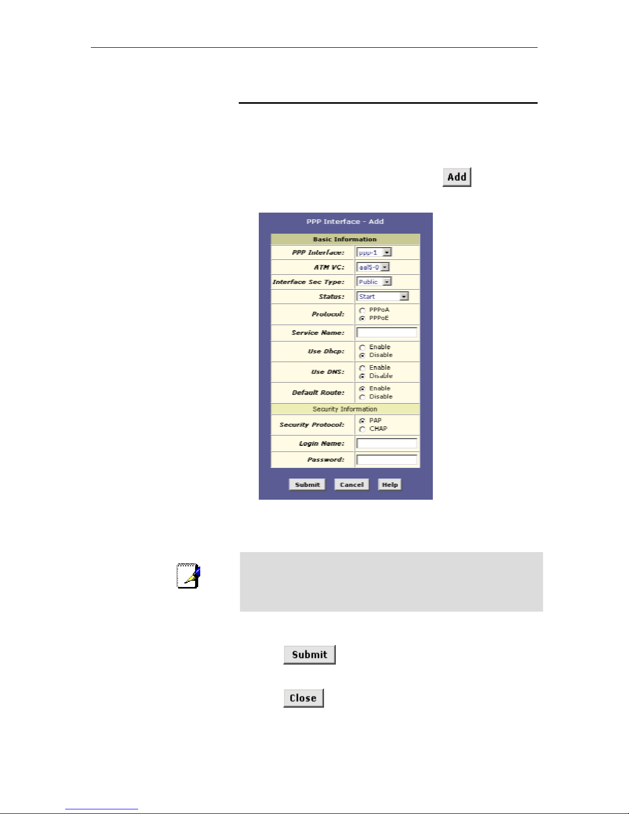
Chapter 13. Configuring PPP Interfaces CellPipeTM 22A-GX ADSL Ethernet Router User Manual
Adding a PPP Interface Definition
If you intend to u se more t han on e ty pe o f se rvi ce fr om your ISP,
the device may be con figur ed with multip le PPP i nt erfac es, e a ch
with unique logo n a nd ot he r prope r tie s. Foll ow t hi s pr oced u re to
define properties for a PPP interface:
1. From the PPP Configuration Page, click
.
The PPP Interface – Add page displays, as shown in Figure 44.
100
Note
Figure 44. PPP Interface – Add Page
2. Select a PPP interface name from the drop-down list, and
then enter or select data for each field.
You can create multiple PPP interfaces only if you are usin g the
PPoA protocol; onl y one PPP in te rfa ce can be de fin ed if yo u a re
using PPoE. Check with your ISP which version of the protocol
they require.
The fields are d e fined in th e ta ble s on pa ge 96 an d 9 8.
3. Click
.
A page displays to confi rm your change s.
4. Click
to return to the PPP page and view the new
interface in the table.
 Loading...