

Page 1

Network Video Recorder
Quick Operation Guide
Page 2

Quick Operation Guide of 87XX-P Series NVR
1
Thank you for purchasing our product. If there is any question or request, please do not hesitate to contact
dealer.
This manual is applicable to the models listed in the following table.
Series
Model
Type
87XX-P series
4CH(4 POE)
8CH(4 POE)
8CH(8 POE)
16CH(8 POE)
16CH(16 POE)
Network Video Recorder
NVR Pre-Installation
This series NVR are highly advanced surveillance equipment that should be installed with care. Please take into
consideration the following precautionary steps before installation of the NVR.
1. Keep all liquids away from the NVR.
2. Install the NVR in a well-ventilated and dust-free area.
3. Ensure environmental conditions meet factory specifications.
4. Install a manufacturer recommended HDD.
NVR Installation
During the installation of the NVR:
1. Use brackets for rack mounting.
2. Ensure there is ample room for audio and video cables.
3. When installing cables, ensure that the bend radius of the cables are no less than five times than its diameter.
4. Connect both the alarm and RS-485 cable.
5. Allow at least 2cm (≈0.75-inch) of space between racks mounted devices.
6. Ensure the NVR is grounded.
7. Environmental temperature should be within the range of -10 ºC ~ 55 ºC, 14ºF ~ 131ºF.
8. Environmental humidity should be within the range of 10% ~ 90%.
Hard Disk Installation
Before you start:
Before installing a hard disk drive (HDD), please make sure the power is disconnected from the NVR. A factory
recommended HDD should be used for this installation.
Up to 2 SATA hard disks can be installed on your NVR.
Tools Required: Screwdriver.
Steps (for 87XX Series):
Note: The installation steps of 8/16 Series is the same as 4ch series, so we take the installation steps of 4ch as
example.
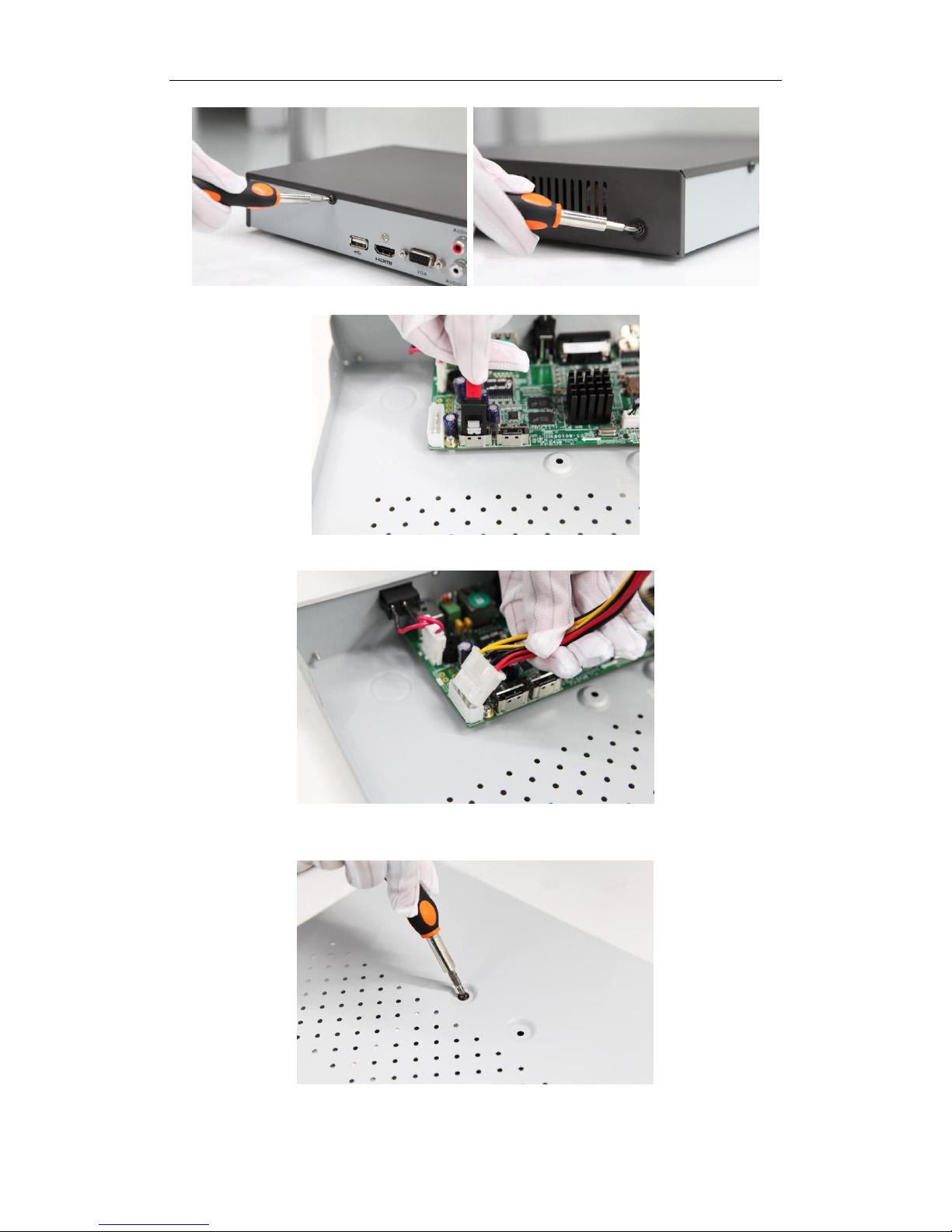
1. Remove the cover from the NVR by unfastening the screws on the back and side.
Page 3
Quick Operation Guide of 87XX-P Series NVR
2
2. Connect one end of the data cable to the motherboard of NVR and the other end to the HDD.
3. Connect the power cable to the HDD.
4. Place the HDD on the bottom of the device and then fasten the screws on the
bottom to fix the HDD.
5. Re-install the cover of the NVR and fasten screws.
Page 4
Quick Operation Guide of 87XX-P Series NVR
3
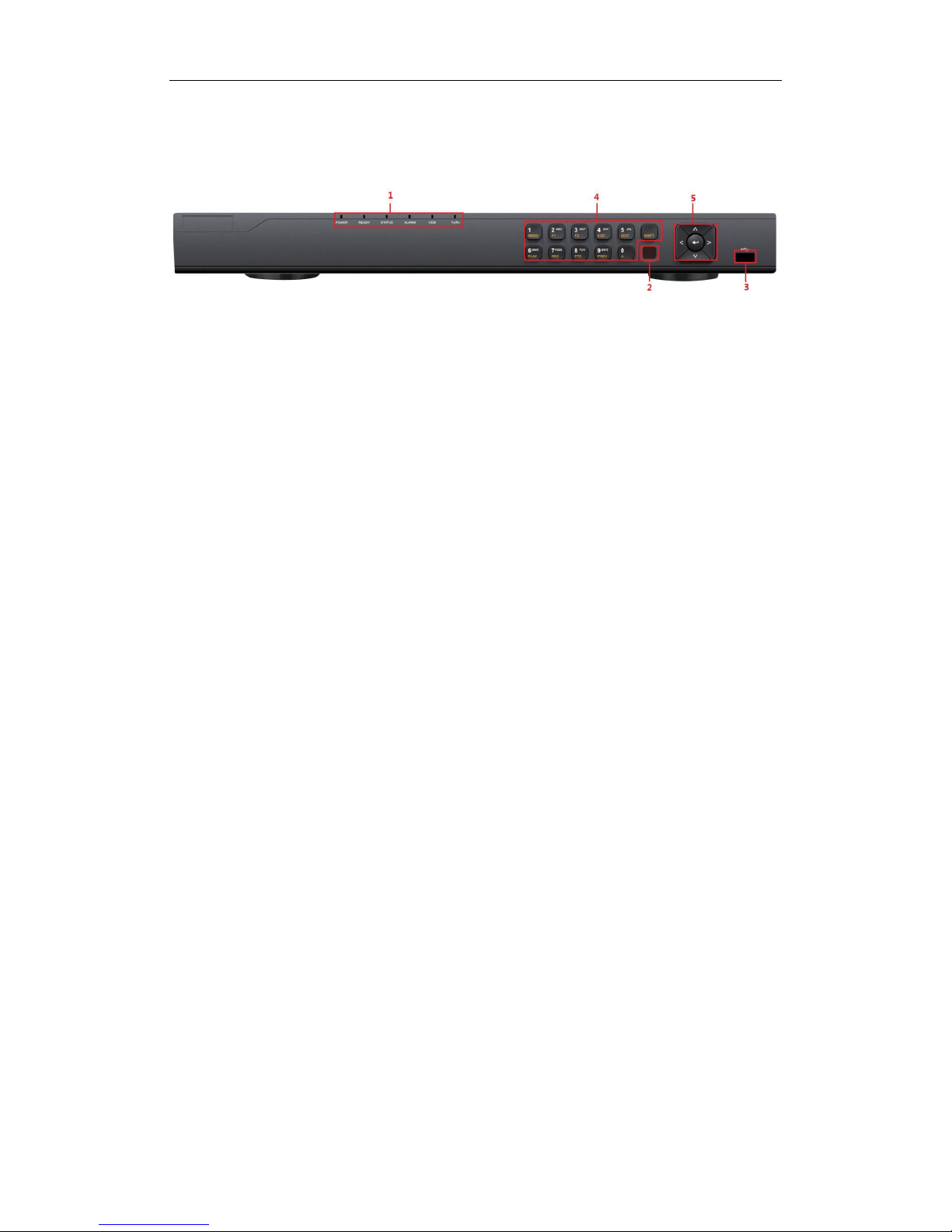
Front Panel
87XX-P Series
① Status Indicators (Alarm, Ready, Status, HDD, power, Tx/Rx)
② USB Interfaces
③ Composite Keys
④ SHIFT
⑤ Compound Buttons
Page 5
Quick Operation Guide of 87XX-P Series NVR
4
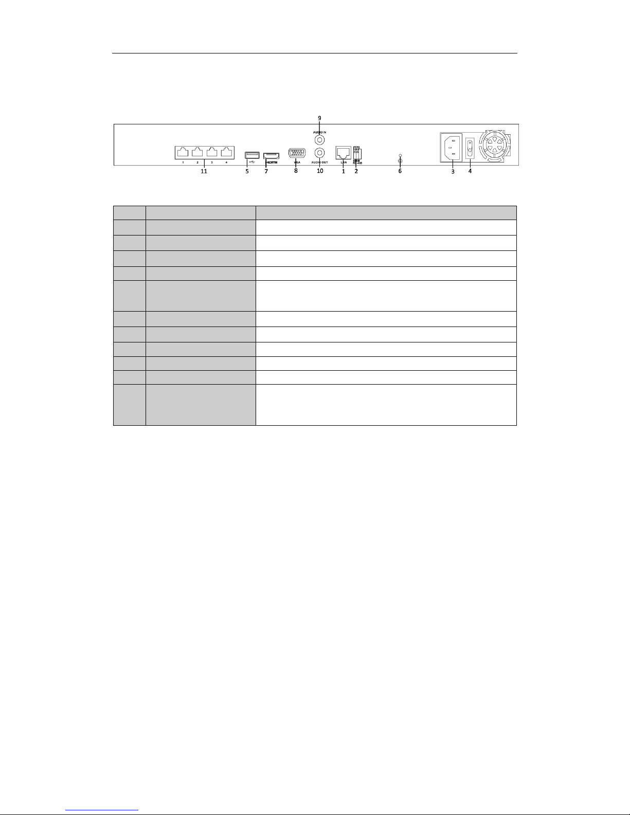
Rear Panel
87XX-P Series(with 4 POE)
Note: The rear panels of others provide 8 POE/16 POE interfaces.
No.
Item
Description
1
LAN Network Interface
Connector for LAN (Local Area Network).
2
RS-485 Interface
Connects to RS-485 devices.
3
Power Supply
100~240VAC power supply
4
Power Switch
Switch for turning on/off the device.
5
USB Interface
Universal Serial Bus (USB) ports for additional devices such as USB
mouse and USB Hard Disk Drive (HDD).
6
GND
Ground (needs to be connected when NVR starts up).
7
HDMI Interface
HDMI video output connector.
8
VGA Output
DB9 connector for VGA output. Display local video output and menu.
9
Audio In
RCA connector for voice talk input
10
Audio Out
RCA connector for audio output
11
Network Interfaces with
PoE function
(for B Series)
Network interface for the cameras and to provide power over
Ethernet.
Page 6
Quick Operation Guide of 87XX-P Series NVR
5
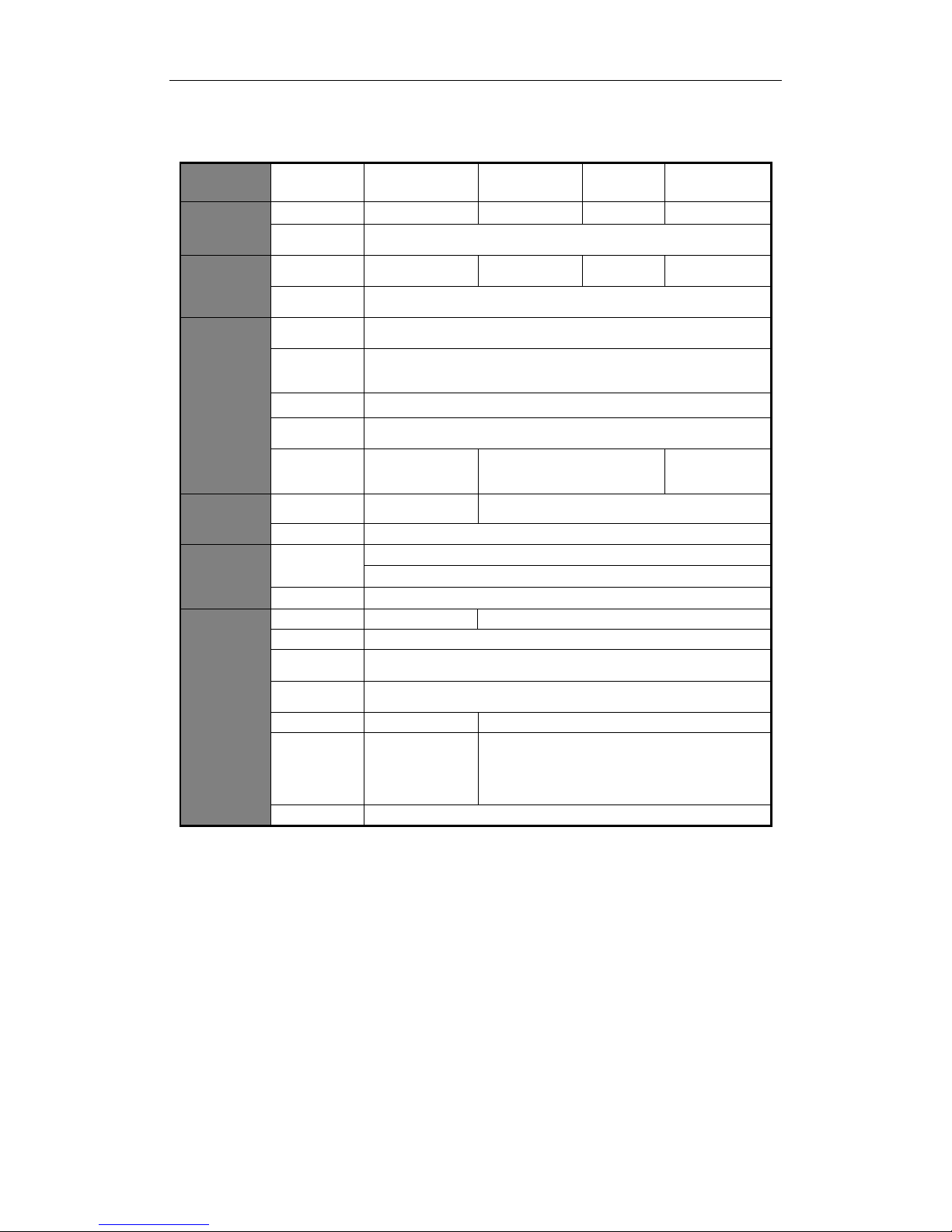
Specifications
Model
4CH-P4
8CH- P8
16CH-P8
16CH-P16
Video/Audi
o input
IP video input
4-ch
8-ch
16-ch
16-ch
Two-way
audio input
1-ch, RCA (2.0 Vp-p, 1kΩ)
Bandwidth
Incoming
bandwidth
25Mbps
50Mbps
100Mbps
160Mbps
Output
bandwidth
80Mbps
Video/Audi
o output
Decoding
resolution
6MP/5MP/3MP/1080P/UXGA/720P/VGA/4CIF/DCIF/2CIF/CIF/QCIF
HDMI/VGA
output
1-ch, resolution:
1920 × 1080P /60Hz, 1600 × 1200 /60Hz, 1280 × 1024 /60Hz, 1280 × 720
/60Hz, 1024 × 768 /60Hz
Audio output
1-ch, RCA (Linear, 1kΩ)
Playback
resolution
6MP/5MP/3MP/1080P/UXGA/720P/VGA/4CIF/DCIF/2CIF/CIF/QCIF
Synchronous
playback
4-ch, 720P
2-ch, 1080P
8-ch@720P
6-ch@1080P
16-ch@4CIF,
12-ch@720P,
6-ch@1080P
Hard disk
SATA
1 SATA interface
for 1 HDD
2 SATA interfaces for 2 HDDs
Capacity
Up to 6TB for each disk
External
interface
Network
interface
1 RJ-45 10 /100 /1000 Mbps self-adaptive Ethernet interface
4/8/16 independent 10 /100 Mbps PoE Ethernet interfaces
USB interface
2 × USB 2.0
Others
Power supply
48V DC
100~240VAC, 47~63Hz, 3A
Consumption
≤ 15 W (without hard disk)
Working
temperature
-10 ºC ~ +55 ºC (14 ºF ~ 131 ºF)
Working
humidity
10 % ~ 90 %
Chassis
1U chassis
19-inch rack-mounted 1U chassis
Dimensions
(W × D × H)
315 × 230 ×
45mm
(12.4 ×9.1 × 1.8
inch)
445 × 290 × 45mm (17.5 ×11.4 × 1.8 inch)
Weight
≤ 2 Kg (4.4 lb) (without hard disk)
Page 7

Quick Operation Guide of 87XX-P Series NVR
6
HDD Storage Calculation Chart
The following chart shows an estimation of storage space used based on recording at one channel for an hour at
a fixed bit rate.
Bit Rate
Storage Used
96K
42M
128K
56M
160K
70M
192K
84M
224K
98M
256K
112M
320K
140M
384K
168M
448K
196M
512K
225M
640K
281M
768K
337M
896K
393M
1024K
450M
1280K
562M
1536K
675M
1792K
787M
2048K
900M
4096K
1.8G
8192K
3.6G
16384K
7.2G
Note: Please note that supplied values for storage space used is just for reference. Storage space used is
estimated by formulas and may have some deviation from actual value.
Page 8

Quick Operation Guide of 87XX-P Series NVR
7
Menu Operation
Menu Structure
Menu
Export
Manual
HDD Camera
Maintenance
Shutdown
Record
Configuration
Playback
Normal
Record
General
Schedule Camera General
System Info
Logout
Event
Advanced
Parameters OSD
Network
Log
Information
Shutdown
Advanced
Image
Import/
Export
Reboot
Holiday PTZ
Upgrade
Motion
Live View Default
Privacy
Mask
Exceptions
Net Detect
Video
Tampering
User
Video Loss
HDD Detect
Alarm
RS-232
VCA
Normal
Event
Tag
Smart
Sub-periods
External
File
VCA Search
Behavior
Search
Face Search
People
Counting
Heat Map
Alarm
Hot Spare
Startup and Shutdown
Proper startup and shutdown procedures are crucial to expanding the life of the NVR.
To start your NVR:
1. Check the power supply is plugged into an electrical outlet. It is HIGHLY recommended that an
Uninterruptible Power Supply (UPS) be used in conjunction with the device. The Power indicator LED on the
front panel should be red, indicating the device gets the power supply.
2. Turn on the power switch on the rear panel to start the NVR immediately.
To shut down the NVR:
1. Enter the Shutdown menu.
Menu > Shutdown
Shutdown Menu
2. Select the Shutdown button.
3. Click the Yes button.
4. Shut the power switch down when the shutdown attention pops up.
Page 9

Quick Operation Guide of 87XX-P Series NVR
8
Setting the Admin Password
Purpose:
For the first-time access, you need to activate the device by setting an admin password. No operation is allowed
before activation. You can also activate the device via Web Browser, SADP or Client Software.
Steps:
1. Input the same password in the text field of Create New Password and Confirm New Password.
STRONG PASSWORD RECOMMENDED– We highly recommend you create a strong password of your
own choosing (using a minimum of 8 characters, including upper case letters, lower case letters,
numbers, and special characters) in order to increase the security of your product. And we recommend
you reset your password regularly, especially in the high security system, resetting the password
monthly or weekly can better protect your product.
2. Click OK to save the password and activate the device.
For the old version device, if you update it to the new version, the following dialog box will pop up once the
device starts up. You can click YES and follow the wizard to set a strong password.
Page 10

Quick Operation Guide of 87XX-P Series NVR
9
Login and Logout
User Login
Purpose:
If NVR has logged out, you must login the device before operating the menu and other functions.
Steps:
1. Select the User Name in the dropdown list.
2. Input Password.
3. Click OK to log in.
The device gets locked for 60 seconds if the admin user performs 7 failed password attempts (5 attempts for the
guest/operator).
User Logout
Purpose:
After logging out, the monitor turns to the live view mode and if you want to do some operation, you need to
enter user name and password tog in again.
Steps:
1. Enter the Shutdown menu.
Menu > Shutdown
2. Click Logout.
After you have logged out the system, menu operation on the screen is invalid. It is required to input a user name
and password to unlock the system.
Page 11

Quick Operation Guide of 87XX-P Series NVR
10
Using the Start Wizard
Purpose:
After admin password is set, the setup wizard pops up automatically. It can walk you through some basic settings
of the NVR.
Start Wizard Interface
Steps:
1. If you don’t want to use the setup wizard at that moment, click the Exit button. You can also choose to use
the Setup Wizard next time by leaving the “Start wizard when the device starts?” checkbox checked.
2. Click the Next button to enter the Date and Time Settings interface.
Date and Time Settings
3. After the time settings, click Next button which takes you back to the Basic Network Setup Wizard
interface.
Page 12

Quick Operation Guide of 87XX-P Series NVR
11
Network Configuration
The dual-NIC network 10 /100/1000 Mbps self-adaptive Ethernet interfaces are provided for the
DS-8600NI-E8 and DS-7700NI-E4 series NVR;one 10 /100 Mbps self-adaptive Ethernet interface for
DS-7604/7608NI-E1(E2) series NVR; and one 10 /100/1000 Mbps self-adaptive Ethernet interface for
other models.
For the models have the PoE or built-in switch network interfaces, including DS-7600NI-E1(E2)/N,
DS-7600NI-E1(E2)/P and DS-7700NI-E4/P series NVR, the internal NIC IPv4 address should be configured
for the cameras connecting to the PoE or built-in switch network interface of the NVR.
4. Click Next button after you configured the basic network parameters. Then you will enter the Cloud P2P
interface. Configure the Cloud P2P according to your need.
Advanced Network Parameters
5. Click Next button to enter the Advanced Network Parameter interface. You can enable PPPoE, enable
DDNS and set other ports according to your need.
Page 13

Quick Operation Guide of 87XX-P Series NVR
12
Advanced Network Parameters
6. After configuration finishes, click Next button to enter HDD Management interface.
HDD Management
7. To initialize the HDD, click the Init button. Initialization removes all the data saved in the HDD.
8. Click Next button to enter the IP Camera Management interface.
9. Click Search to search the online IP Camera and the Security status shows whether it is active or inactive.
Before adding the camera, make sure the IP camera to be added is in active status.
If the camera is in inactive status, you can click the inactive icon of the camera to set the password to
activate it. You can also select multiple cameras from the list and click the One-touch Activate to activate
the cameras in batch.
Click the Add to add the camera.
Page 14

Quick Operation Guide of 87XX-P Series NVR
13
IP Camera Management
10. Click Next button. Configure the recording for the searched IP Cameras.
Record Settings
11. Click OK to complete the startup Setup Wizard.
Live View
Some icons are provided on screen in Live View mode to indicate different camera status. These icons include:
Live View Icons
In the live view mode, there are icons at the right top of the screen for each channel, showing the status of the
record and alarm in the channel, so that you can find problems as soon as possible.
Alarm (video loss, tampering, motion detection or sensor alarm).
Record (manual record, schedule record, motion detection or alarm triggered record)
Alarm & Record
Page 15

Quick Operation Guide of 87XX-P Series NVR
14
Adding and Configuring IP Cameras
You should add and configure the online IP cameras to enable the live view and recording function.
Adding IP Cameras
You can search and add the online IP cameras by following the startup wizard, or according to the following
steps.
Steps:
1. Enter the Camera Management interface.
Menu> Camera> Camera
Main Menu
2. To add the online cameras with same network segment:
1) Click Search to search the online cameras.
Camera Settings Interface
2) Check the checkbox of certain cameras to be added.
Page 16

Quick Operation Guide of 87XX-P Series NVR
15
3) Click Quick Add to add the camera.
3. To add other IP cameras:
1) On the left side of the interface, you can enter the IP address, protocol, management port, and other
information of the IP camera to be added.
2) Click Add to add the camera.
Note: If you check the Synchronize IP Camera checkbox, the default settings of the NVR for the IP
camera is applied to the added camera.
Configuring Basic Parameters of IP Cameras
After the adding of the IP cameras, the basic information of the camera lists in the page, and you can configure
the basic setting of the IP cameras.
Steps:
1. Click the icon to edit the parameters; you can edit the IP address, protocol and other parameters.
Edit the Parameters
2. Click apply to save the settings and click OK to exit the editing interface.
To edit more parameters:
1. Click the Advance Set icon.
Network Configuration of the Camera
2. You can edit the network information and the password of the camera.
Page 17

Quick Operation Guide of 87XX-P Series NVR
16
3. Click Apply to save the settings and click OK to exit the interface.
Explanation of the icons:
Edit basic parameters of the camera
Get the live view of the camera
PTZ Control
Follow the procedure to set the parameters for PTZ. The configuring of the PTZ parameters should be done
before you set the PTZ camera.
Before you start, please check that the PTZ and the NVR are connected properly through RS-485 interface.
PTZ Settings
Steps:
1. Enter the PTZ Settings interface.
Menu >Camera> PTZ
Camera Settings Interface
2. Choose the camera for PTZ setting next to Camera label.
3. Enter the parameters of the PTZ camera.
Note: All the parameters should be exactly the same as the PTZ camera parameters.
4. Click Copy if you want to configure same settings to other PTZ cameras.
5. Click the Apply button to save and exit the interface.
PTZ Control
In the Live View mode, you can press the PTZ Control button on the front panel or on the remote, or choose the
PTZ Control icon to enter the PTZ toolbar.
Page 18

Quick Operation Guide of 87XX-P Series NVR
17
PTZ Control Bar
Description of the PTZ toolbar icons
Icon
Description
Icon
Description
Icon
Description
Direction button
and the auto-cycle
button
Zoom+, Focus+,
Iris+
Zoom-, Focus-, Iris-
The speed of the
PTZ movement
Light on/off
Wiper on/off
3D-Zoom
Image
Centralization
Preset
Patrol
Pattern Menu
Previous item
Next item
Start pattern/patrol
Stop the patrol or
pattern movement
Minimize
windows
Exit
Page 19

Quick Operation Guide of 87XX-P Series NVR
18
Playback
Play back the record files of a specific channel in the live view menu. Channel switch is supported.
Instant playback by channel
Steps:
Choose a channel in live view mode using the mouse and click the button in the quick setting toolbar.
Note: In the instant playback mode, only record files recorded during the last five minutes on this channel will
be played back.
Instant Playback Interface
Playback by channel
Steps:
1. Enter the Playback menu.
Mouse: right click a channel in live view mode and select Playback from the menu.
Right-click Menu under Live View
Front Panel: press PLAY button to play back record files of the channel under single-screen live view.
Under multi-screen live view, record files of the top left channel (not masked) will be played back.
Note: pressing numerical buttons will switch playback to related channels during playback process.
2. Playback management.
The toolbar in the bottom part of Playback interface can be used to control playing process.
Page 20

Quick Operation Guide of 87XX-P Series NVR
19
Playback Interface
Just check the channel or channels if you want to switch playback to another channel or execute
simultaneous playback of multiple channels.
Export
Recorded files can be backed up to various devices, such as USB flash drives, USB HDDs or a DVD writer.
Steps:
1. Enter Video Export interface.
Choose the channel(s) you want to back up and click on the Search button.
Quick Export Interface
2. Check Search result.
Choose the record file in Export interface and press button to check it. Then click Export button.
3. Enter Export interface, choose backup device and press Export button to start exporting.
Page 21

Quick Operation Guide of 87XX-P Series NVR
20
Quick Export using USB1-1
Checkup of Quick Export Result Using USB1-1
Page 22

Quick Operation Guide of 87XX-P Series NVR
21
Accessing by Web Browser
Logging In
If the device has successfully connected to the network, you can get access to the device via web browser. Open
web browser, input the IP address of the device and then press Enter. The login interface appears.
Input the user name and password, and click the Login button.
Notes:
1. The default IP address is 192.0.0.64.
2. The default user name is admin, and password is 12345.
3. You may use one of the following listed web browsers: Internet Explorer 6.0, Internet Explorer 7.0, Internet
Explorer 8.0, Internet Explorer 9.0, Internet Explorer 10.0, Apple Safari, Mozilla Firefox, and Google Chrome.
4. The supported resolutions include 1024*768 and above.
When you log in for the first time, the system will remind you to install the Plug-in control. After the installation,
you can configure and manage the device remotely.
Live View
The live view interface appears by default when you log in the device.
Interface Introduction
① Camera List: Displays the list of cameras and the playing and recording status of each camera.
② Live View Window: Displays the image of camera, and multi-window division is supported.
③ Play Control Bar: Play control operations are supported.
④ PTZ Control: Pan, tilt, zoom operations are supported, as well as preset editing and calling.
Note: PTZ function can only be realized if the connected camera supports PTZ control.
Page 23

Quick Operation Guide of 87XX-P Series NVR
22
Start Live View
Steps:
1. In the live view window, select a playing window by clicking the mouse.
2. Double-click a camera from the device list to start the live view.
3. You can click the button on the toolbar to start the live view of all cameras on the device list.
Refer to the following table for the description of buttons on the live view window:
Icon
Description
Icon
Description
Select the
window-division
mode
/
Start/Stop all live view
Capture pictures in
the live view mode
/
Start/Stop all
recording
Previous page
Next page
/
Open/Close audio
/
Start/Stop two-way
audio
Adjust volume
/
Enable/Disable digital
zoom
Full-screen
/
Main/Sub Stream
Recording
Before you start
Make sure the device is connected with HDD or network disk, and the HDD or network disk has been initialized
for the first time to use.
Two recording types can be configured: Manual and Scheduled. The following section introduces the
configuration of scheduled recording.
Steps:
1. Click Remote Configuration> Camera Settings> Record Schedule to enter Record Schedule settings interface.
2. Select the camera to configure the record schedule.
3. Check the checkbox of Enable Record Schedule to enable recording schedule.
4. Click Edit to edit record schedule.
5. Choose the day in a week to configure scheduled recording.
1) Configure All Day or Customize record:
If you want to configure the all-day recording, please check the All Day checkbox.
If you want to record in different time sections, check the Customize checkbox. Set the Start Time and
End Time.
Note: The time of each segment can’t be overlapped. Up to 8 segments can be configured.
2) Select a Record Type. The record type can be Normal, Motion, Alarm, Motion & Alarm, and Motion |
Alarm.
3) Check the checkbox of Select All and click Copy to copy settings of this day to the whole week. You can
also check any of the checkboxes before the date and click Copy.
4) Click OK to save the settings and exit the Edit Schedule interface.
6. Click Advanced to configure advanced record parameters.
7. Optionally, check the checkboxes of other cameras to copy the settings to.
Page 24

Quick Operation Guide of 87XX-P Series NVR
23
8. Click Save to validate the above settings.
Playback
Interface Introduction
① Camera List: Displays the list of cameras and the playing status of each camera.
② Playback Window: Displays the video of camera.
③ Play Control Bar: Play control operations are supported.
④ Time Line: Displays the time bar and the records marked with different colors.
⑤ Playback Status: Displays the playback status, including camera No. and playback speed.
⑥ Calendar: You can select the date to play.
Start Playback
Steps:
1. Click Playback on the menu bar to enter playback interface.
2. Click the camera from the device list for playback.
3. Select the date from the calendar and click Search.
Note: The day with record will be marked like .
4. Click the button to play the video file searched on the current date.
5. Use the buttons on the toolbar to operate in playback mode.
Button
Description
Button
Description
/
Play/Pause Stop
Slow down
Speed up
Play by single frame
Capture
Stop All Playback
Download
/
Video Clip
/
Open/Close audio
Full-screen
6. You can drag the progress bar with the mouse to locate the exact playback point. You can also input the
time in the textbox and click button to locate the playback point.
Page 25

Quick Operation Guide of 87XX-P Series NVR
24
The color of the video on the progress bar stands for the different video types.
 Loading...