


Digital Video Recorder
User Manual

Digital Video Recorder User Manual
User Manual
About this Manual
This Manual is applicable to HD Digital Video Recorder (DVR).
The Manual includes instructions for using and managing the product. Pictures, charts, images and all other information hereinafter are for description and explanation only. The information contained in the Manual is subject to change, without notice, due to firmware updates or other reasons. Please find the latest version in the company website.
Please use this user manual under the guidance of professionals.
Legal Disclaimer
REGARDING TO THE PRODUCT WITH INTERNET ACCESS, THE USE OF PRODUCT SHALL BE WHOLLY AT YOUR OWN RISKS. OUR COMPANY SHALL NOT TAKE ANY RESPONSIBILITES FOR ABNORMAL OPERATION, PRIVACY LEAKAGE OR OTHER DAMAGES RESULTING FROM CYBER ATTACK, HACKER ATTACK, VIRUS INSPECTION, OR OTHER INTERNET SECURITY RISKS; HOWEVER, OUR COMPANY WILL PROVIDE TIMELY TECHNICAL SUPPORT IF REQUIRED.
SURVEILLANCE LAWS VARY BY JURISDICTION. PLEASE CHECK ALL RELEVANT LAWS IN YOUR JURISDICTION BEFORE USING THIS PRODUCT IN ORDER TO ENSURE THAT YOUR USE CONFORMS THE APPLICABLE LAW. OUR COMPANY SHALL NOT BE LIABLE IN THE EVENT THAT THIS PRODUCT IS USED WITH ILLEGITIMATE PURPOSES.
IN THE EVENT OF ANY CONFLICTS BETWEEN THIS MANUAL AND THE APPLICABLE LAW, THE LATER PREVAILS.
1

Digital Video Recorder User Manual
Regulatory Information
FCC Information
Please take attention that changes or modification not expressly approved by the party responsible for compliance could void the user’s authority to operate the equipment.
FCC compliance: This equipment has been tested and found to comply with the limits for a Class A digital device, pursuant to part 15 of the FCC Rules. These limits are designed to provide reasonable protection against harmful interference when the equipment is operated in a commercial environment. This equipment generates, uses, and can radiate radio frequency energy and, if not installed and used in accordance with the instruction manual, may cause harmful interference to radio communications. Operation of this equipment in a residential area is likely to cause harmful interference in which case the user will be required to correct the interference at his own expense.
FCC Conditions
This device complies with part 15 of the FCC Rules. Operation is subject to the following two conditions:
1.This device may not cause harmful interference.
2.This device must accept any interference received, including interference that may cause undesired operation.
EU Conformity Statement
This product and - if applicable - the supplied accessories too are marked with "CE" and comply therefore with the applicable harmonized European standards listed under the EMC Directive 2014/30/EU, the LVD Directive 2014/35/EU, the RoHS Directive 2011/65/EU.
2012/19/EU (WEEE directive): Products marked with this symbol cannot be disposed of as unsorted municipal waste in the European Union. For proper recycling, return this product to your local supplier upon the purchase of equivalent new equipment, or
dispose of it at designated collection points. For more information see: www.recyclethis.info
2006/66/EC (battery directive): This product contains a battery that cannot be disposed of as unsorted municipal waste in the European Union. See the product documentation for specific battery information. The battery is marked with this symbol, which may include
lettering to indicate cadmium (Cd), lead (Pb), or mercury (Hg). For proper recycling, return the battery to your supplier or to a designated collection point. For more information see: www.recyclethis.info
Industry Canada ICES-003 Compliance
This device meets the CAN ICES-3 (A)/NMB-3(A) standards requirements.
2
Digital Video Recorder User Manual
Applicable Models
This manual is applicable to the models listed in the following table.
Series Model
LTD8404K-ST
LTD8408K-ST 84XXK-ST LTD8416K-ST LTD8424K-ST
LTD8432K-ST
Symbol Conventions
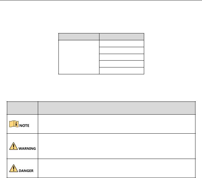
The symbols that may be found in this document are defined as follows.
Symbol Description
Provides additional information to emphasize or supplement important points of the main text.
Indicates a potentially hazardous situation, which if not avoided, could result in equipment damage, data loss, performance degradation, or unexpected results.
Indicates a hazard with a high level of risk, which if not avoided, will result in death or serious injury.
Safety Instructions
Proper configuration of all passwords and other security settings is the responsibility of the installer and/or end-user.
In the use of the product, you must be in strict compliance with the electrical safety regulations of the nation and region. Please refer to technical specifications for detailed information.
Input voltage should meet both the SELV (Safety Extra Low Voltage) and the Limited Power Source with 100 to 240 VAC, 12 VDC or 48 VDC according to the IEC60950-1 standard. Please refer to technical specifications for detailed information.
Do not connect several devices to one power adapter as adapter overload may cause over-heating or a fire hazard.
Please make sure that the plug is firmly connected to the power socket.
If smoke, odor or noise rise from the device, turn off the power at once and unplug the power cable, and then please contact the service center.
3

Digital Video Recorder User Manual
Preventive and Cautionary Tips
Before connecting and operating your device, please be advised of the following tips:
Ensure unit is installed in a well-ventilated, dust-free environment.
Unit is designed for indoor use only.
Keep all liquids away from the device.
Ensure environmental conditions meet factory specifications.
Ensure unit is properly secured to a rack or shelf. Major shocks or jolts to the unit as a result of dropping it may cause damage to the sensitive electronics within the unit.
Use the device in conjunction with an UPS if possible.
Power down the unit before connecting and disconnecting accessories and peripherals.
A factory recommended HDD should be used for this device.
Improper use or replacement of the battery may result in hazard of explosion. Replace with the same or equivalent type only. Dispose of used batteries according to the instructions provided by the battery manufacturer.
Ensure to use the attached power adaptor only and not to change the adaptor randomly.
The USB flash drive can only connect to mouse or keyboard.
Use only power supplies listed in the user instructions.
4

Digital Video Recorder User Manual
Product Key Features
General
Connectable to HD and analog cameras;
Supports UTC (Coaxitron) protocol for connecting camera over coax;
Connectable to AHD cameras;
Connectable to HDCVI cameras;
Connectable to IP cameras;
The analog signal inputs including HD, AHD, HDCVI, and CVBS can be automatically recognized without configuration;
Each channel supports dual-stream. And sub-stream supports up to WD1 resolution;
The main stream of LTD84XXK-ST series supports up to 5 MP resolution of all the channels;
For LTD84XXK-ST series DVR, 5 MP long distance transmission can be enabled for the analog cameras;
Independent configuration for each channel, including resolution, frame rate, bit rate, image quality, etc.;
The minimum frame rate for main stream and sub-stream is 1 fps;
Encoding for both video stream and video & audio stream; audio and video synchronization during composite stream encoding;
Supports enabling H.265+/H.264 ZIP+ to ensure high video quality with lowered bit rate;
H.265+/H.265/H.264 ZIP+/H.264 encoding for the main stream, and H.265/H.264 encoding for the sub-stream of analog cameras;
Connectable to H.265 and H.264 IP cameras;
Defog level, night to day sensitivity, day to night sensitivity, IR light brightness, day/night mode, and WDR switch configurable for the connected analog cameras supporting these parameters;
4 MP/5 MP signal switch for the supported analog cameras;
Watermark technology.
Local Monitoring
HDMI output at up to 4K (3840 × 2160) resolution;
For LTD84XXK-ST series, there are two HDMI interfaces of which the HDMI1 and VGA interfaces share simultaneous output. For HDMI1/VGA output, up to 1920 × 1080 resolution is supported. For HDMI2 output, up to 4K (3840 × 2160) resolution is supported;
1/4/6/8/9/16/25/36 screen live view is supported, and the display sequence of screens is adjustable;
5

Digital Video Recorder User Manual
For LTD8424K-ST and LTD8432K-ST series DVR, up to 32-window division mode is supported for VGA/HDMI1 output, and up to 16-window division mode is supported for CVBS output. For the HDMI2 output, if the resolution is lower than 4K, up to 36-window division mode is supported; if the resolution is 4K, up to 64-window division mode is supported.
For LTD84XXK-ST series DVR, if the sum of the analog and IP channels exceeds 25, up to 32-window division mode is supported for the VGA/HDMI1 output.
Live view screen can be switched in group and manual switch and automatic cycle live view are also provided, the interval of automatic cycle can be adjusted;
CVBS output only serves as the aux output or live view output.
Quick setting menu is provided for live view;
The selected live view channel can be shielded;
VCA information overlay in live view for the supported analog cameras and in smart playback for the supported analog and IP cameras;
Motion detection, video-tampering detection, video exception alarm, video loss alarm and VCA alarm functions;
For LTD84XXK-ST series DVR, 1-ch analog camera supports people counting and heat map functions;
LTD84XXK-ST series support line crossing detection and intrusion detection of all channels, and 2-ch sudden scene change detection. For the analog channels, the line crossing detection and intrusion detection conflict with other VCA detection such as sudden scene change detection, face detection and vehicle detection. You can only enable one function;
For LTD84XXK-ST series DVR, the enhanced VCA mode conflicts with the 2K/4K output and 4 MP/5 MP signal input;
Privacy mask;
Several PTZ protocols (including Omnicast VMS of Genetec) supported; PTZ preset, patrol and pattern;
Zooming in/out by clicking the mouse and PTZ tracing by dragging mouse.
HDD Management
Each disk with a maximum of 8 TB storage capacity for LTD84XXK-ST;
8 network disks (8 NAS disks, 8 IP SAN disks or n NAS disks + m IP SAN disks (n+m ≤ 8)) can be connected;
Remaining recording time of the HDD can be viewed;
Supports cloud storage;
S.M.A.R.T. and bad sector detection;
HDD sleeping function;
HDD property: redundancy, read-only, read/write (R/W);
HDD group management;
HDD quota management; different capacity can be assigned to different channels.
6

Digital Video Recorder User Manual
For LTD84XXK-ST series, hot-swappable HDD supporting RAID0, RAID1, RAID5, RAID 6 and RAID10 storage scheme, and can be enabled and disabled on your demand. And 16 arrays can be configured.
Recording, Capture and Playback
Capture is supported by LTD84XXK-ST series DVR only.
Holiday recording schedule configuration;
Cycle and non-cycle recording modes;
Normal and event video encoding parameters;
Multiple recording types: manual, continuous, alarm, motion, motion | alarm, motion & alarm and event;
Supports POS triggered recording for LTD84XXK-ST series DVR;
8 recording time periods with separated recording types;
Supports Channel-Zero encoding;
Main stream and sub-stream configurable for simultaneous recording;
Pre-record and post-record for motion detection triggered recording, and pre-record time for schedule and manual recording;
Searching record files and captured pictures by events (alarm input/motion detection);
Customization of tags, searching and playing back by tags;
Locking and unlocking of record files;
Local redundant recording and capture;
When HD, AHD, or HDCVI input is connected, the information including the resolution and frame rate will be overlaid on the bottom right corner of the live view for 5 seconds. When CVBS input is connected, the information such as NTSC or PAL will be overlaid on the bottom right corner of the live view for 5 seconds.
Searching and playing back record files by camera number, recording type, start time, end time, etc.;
Smart playback to go through less effective information;
Main stream and sub-stream selectable for local/remote playback;
Zooming in for any area when playback;
Multi-channel reverse playback;
Supports pause, fast forward, slow forward, skip forward, and skip backward when playback, locating by dragging the mouse on the progress bar;
4/8/16-ch synchronous playback;
Manual capture, continuous capture of video images and playback of captured pictures.
Backup
7

Digital Video Recorder User Manual
Exports data by a USB, and SATA device;
Exports video clips when playback;
Video and Log, Video and Player, and Player are selectable to export for backup;
Management and maintenance of backup devices.
Alarm and Exception
Configurable arming time of alarm input/output;
Alarms for video loss, motion detection, video tampering, illegal login, network disconnected, IP confliction, record/capture exception, HDD error, and HDD full, etc.;
Alarm triggers full screen monitoring, audio alarm, notifying surveillance center, sending email and alarm output;
One-key disarms the linkage actions of the alarm input;
PTZ linking for the VCA alarm;
VCA detection alarm is supported;
Supports POS triggered alarm;
Supports coaxial alarm;
System will automatically reboot when a problem is detected in an attempt to restore normal functionality.
LTD8424K-ST and LTD8432K-ST series DVR, you can enable false alarm filer for the motion detection of the PIR cameras. Then only when the motion detection events and PIR events are both triggered, the motion detection alarm will be triggered.
Other Local Functions
Manual and automatic video quality diagnostics;
Operable by mouse and remote control;
Three-level user management; admin user can create many operating account and define their operating permission, which includes the permission to access any channel;
Completeness of operation, alarm, exceptions and log writing and searching;
Manually triggering and clearing alarms;
Importing and exporting of configuration file of devices;
Getting cameras type information automatically;
Unlock pattern for device login for the admin;
Clear-text password available;
GUID file can be exported for password resetting;
Multiple connected analog cameras supporting HD or AHD signal can be upgraded simultaneously via DVR.
Network Functions
8

Digital Video Recorder User Manual
Self-adaptive 1000M network interface;
IPv6 is supported;
TCP/IP protocol, PPPoE, DHCP, DNS, DDNS, NTP, IP PORTAL, SMTP, NFS, iSCSI, UPnP™ and HTTPS are supported;
Supports access by PT Cloud. If you enable PT Cloud, the device will remind you the internet access risk and ask you to confirm the “Terms of Service” and “Privacy Statement” before enabling the service. You should create a verification code to connect to the PT Cloud;
TCP, UDP and RTP for unicast;
Auto/Manual port mapping by UPnPTM;
Remote search, playback, download, locking and unlocking the record files, and downloading files broken transfer resume;
Remote parameters setup; remote import/export of device parameters;
Remote viewing of the device status, system logs and alarm status;
Remote keyboard operation;
Remote HDD formatting and program upgrading;
Remote system restart and shutdown;
Supports upgrading via remote FTP server;
RS-485 transparent channel transmission;
Alarm and exception information can be sent to the remote host;
Remotely start/stop recording;
Remotely start/stop alarm output;
Remote PTZ control;
Two-way audio and voice broadcasting;
Output bandwidth limit configurable;
Embedded WEB server;
If DHCP is enabled, you can enable DNS DHCP or disable it and edit the Preferred DNS Server and Alternate DNS Server.
Development Scalability
SDK for Windows and Linux system;
Source code of application software for demo;
Development support and training for application system.
9
Digital Video Recorder User Manual
|
Table of Contents |
|
Product Key Features ............................................................................................................... |
5 |
|
Chapter 1 Introduction....................................................................................................................... |
16 |
|
1.1 |
Front Panel ....................................................................................................................... |
16 |
1.2 |
IR Remote Control Operations ......................................................................................... |
19 |
1.3 USB Mouse Operation...................................................................................................... |
22 |
|
1.4 |
Input Method Description................................................................................................ |
24 |
1.5 |
Rear Panel ........................................................................................................................ |
24 |
Chapter 2 Getting Started .................................................................................................................. |
28 |
|
2.1 Starting Up and Shutting Down the DVR.......................................................................... |
28 |
|
2.2 |
Activating the Device........................................................................................................ |
29 |
2.3 |
Using the Unlock Pattern for Login .................................................................................. |
31 |
|
2.3.1 Configuring the Unlock Pattern............................................................................... |
31 |
|
2.3.2 Logging in via Unlock Pattern.................................................................................. |
32 |
2.4 |
Basic Configuration in Startup Wizard ............................................................................. |
34 |
2.5 |
Login and Logout.............................................................................................................. |
39 |
|
2.5.1 User Login................................................................................................................ |
39 |
|
2.5.2 User Logout ............................................................................................................. |
40 |
2.6 |
Resetting Your Password .................................................................................................. |
40 |
2.7 Adding and Connecting the IP Cameras........................................................................... |
42 |
|
|
2.7.1 Activating the IP Camera......................................................................................... |
42 |
|
2.7.2 Adding the Online IP Camera .................................................................................. |
43 |
|
2.7.3 Editing the Connected IP Camera ........................................................................... |
46 |
2.8 |
Configuring Signal Input Channel..................................................................................... |
48 |
2.9 |
Configuring 5 MP Long Distance Transmission ................................................................ |
49 |
Chapter 3 Live View ........................................................................................................................... |
50 |
|
3.1 |
Introduction of Live View................................................................................................. |
50 |
3.2 Operations in Live View Mode......................................................................................... |
50 |
|
|
3.2.1 Using the Mouse in Live View................................................................................. |
51 |
|
3.2.2 Switching Main/Aux Output.................................................................................... |
53 |
|
3.2.3 Quick Setting Toolbar in Live View Mode ............................................................... |
53 |
3.3 |
Channel-Zero Encoding .................................................................................................... |
56 |
3.4 |
Adjusting Live View Settings ............................................................................................ |
56 |
10

Digital Video Recorder User Manual
3.5 |
Manual Video Quality Diagnostics................................................................................... |
58 |
Chapter 4 PTZ Controls....................................................................................................................... |
60 |
|
4.1 |
Configuring PTZ Settings .................................................................................................. |
60 |
4.2 |
Setting PTZ Presets, Patrols and Patterns ........................................................................ |
61 |
|
4.2.1 Customizing Presets ................................................................................................ |
61 |
|
4.2.2 Calling Presets ......................................................................................................... |
62 |
|
4.2.3 Customizing Patrols................................................................................................. |
63 |
|
4.2.4 Calling Patrols.......................................................................................................... |
64 |
|
4.2.5 Customizing Patterns .............................................................................................. |
65 |
|
4.2.6 Calling Patterns ....................................................................................................... |
65 |
|
4.2.7 Customizing Linear Scan Limit................................................................................. |
66 |
|
4.2.8 Calling Linear Scan................................................................................................... |
67 |
|
4.2.9 One-Touch Park ....................................................................................................... |
67 |
4.3 PTZ Control Panel ............................................................................................................. |
68 |
|
Chapter 5 Recording and Capture Settings ........................................................................................ |
70 |
|
5.1 |
Configuring Encoding Parameters.................................................................................... |
70 |
5.2 |
Configuring Recording and Capture Schedule ................................................................. |
75 |
5.3 |
Configuring Motion Detection Recording and Capture ................................................... |
78 |
5.4 |
Configuring Alarm Triggered Recording and Capture ...................................................... |
79 |
5.5 |
Configuring Event Recording and Capture ....................................................................... |
81 |
5.6 |
Configuring Manual Recording and Continous Capture .................................................. |
82 |
5.7 |
Configuring Holiday Recording and Capture.................................................................... |
82 |
5.8 |
Configuring Redundant Recording and Capture .............................................................. |
84 |
5.9 Configuring HDD Group.................................................................................................... |
85 |
|
5.10 Files Protection .............................................................................................................. |
86 |
|
5.11 One-Key Enabling and Disabling H.264 ZIP+/H.265+ for Analog Cameras .................... |
88 |
|
Chapter 6 Playback............................................................................................................................. |
90 |
|
6.1 |
Playing Back Record Files ................................................................................................. |
90 |
|
6.1.1 Instant Playback ...................................................................................................... |
90 |
|
6.1.2 Playing Back by Normal Search ............................................................................... |
90 |
|
6.1.3 Playing Back by Event Search .................................................................................. |
93 |
|
6.1.4 Playing Back by Tag ................................................................................................. |
95 |
|
6.1.5 Playing Back by Smart Search ................................................................................. |
98 |
|
6.1.6 Playing Back by System Logs ................................................................................. |
102 |
11

Digital Video Recorder User Manual
|
6.1.7 Playing Back by Sub-Periods.................................................................................. |
103 |
|
|
6.1.8 Playing Back External File...................................................................................... |
104 |
|
|
6.1.9 Playing Back Pictures............................................................................................. |
105 |
|
6.2 |
Auxiliary Functions of Playback...................................................................................... |
106 |
|
|
6.2.1 Playing Back Frame by Frame ............................................................................... |
106 |
|
|
6.2.2 Digital Zoom .......................................................................................................... |
107 |
|
|
6.2.3 Reverse Playback of Multi-Channel....................................................................... |
107 |
|
|
6.2.4 File Management .................................................................................................. |
108 |
|
Chapter 7 Backup ............................................................................................................................. |
109 |
||
7.1 |
Backing up Record Files.................................................................................................. |
109 |
|
|
7.1.1 Backing up by Normal Video/Picture Search........................................................ |
109 |
|
|
7.1.2 Backing up by Event Search................................................................................... |
111 |
|
|
7.1.3 Backing up Video Clips.......................................................................................... |
112 |
|
7.2 Managing Backup Devices.............................................................................................. |
113 |
||
Chapter 8 Alarm Settings ................................................................................................................. |
115 |
||
8.1 |
Setting Motion Detection............................................................................................... |
115 |
|
8.2 |
Setting Sensor Alarms .................................................................................................... |
117 |
|
8.3 |
Detecting Video Loss...................................................................................................... |
119 |
|
8.4 |
Detecting Video Tampering ........................................................................................... |
120 |
|
8.5 |
Setting All-day Video Quality Diagnostics...................................................................... |
121 |
|
8.6 |
Handling Exceptions....................................................................................................... |
123 |
|
8.7 |
Setting Alarm Response Actions .................................................................................... |
124 |
|
Chapter 9 POS Configuration ........................................................................................................... |
127 |
||
9.1 |
Configuring POS Settings................................................................................................ |
127 |
|
9.2 |
Configuring Overlay Channel.......................................................................................... |
131 |
|
9.3 |
Configuring POS Alarm................................................................................................... |
132 |
|
Chapter 10 VCA Alarm ..................................................................................................................... |
134 |
||
10.1 |
Face Detection.............................................................................................................. |
134 |
|
10.2 |
Vehicle Detection ......................................................................................................... |
134 |
|
10.3 |
Line Crossing Detection................................................................................................ |
135 |
|
10.4 |
Intrusion Detection ...................................................................................................... |
137 |
|
10.5 |
Region Entrance Detection .......................................................................................... |
139 |
|
10.6 |
Region Exiting Detection .............................................................................................. |
140 |
|
10.7 |
Loitering Detection....................................................................................................... |
140 |
|
12

Digital Video Recorder User Manual
10.8 |
People Gathering Detection......................................................................................... |
140 |
10.9 |
Fast Moving Detection ................................................................................................. |
141 |
10.10 Parking Detection....................................................................................................... |
141 |
|
10.11 Unattended Baggage Detection ................................................................................. |
141 |
|
10.12 Object Removal Detection ......................................................................................... |
142 |
|
10.13 Audio Exception Detection......................................................................................... |
142 |
|
10.14 Defocus Detection...................................................................................................... |
143 |
|
10.15 Sudden Scene Change................................................................................................ |
144 |
|
10.16 PIR Alarm.................................................................................................................... |
144 |
|
Chapter 11 VCA Search .................................................................................................................... |
145 |
|
11.1 |
Face Search................................................................................................................... |
145 |
11.2 |
Behavior Search............................................................................................................ |
147 |
11.3 |
Plate Search.................................................................................................................. |
148 |
11.4 |
People Counting........................................................................................................... |
149 |
11.5 Heat Map...................................................................................................................... |
150 |
|
Chapter 12 Network Settings ........................................................................................................... |
152 |
|
12.1 |
Configuring General Settings ....................................................................................... |
152 |
12.2 |
Configuring Advanced Settings .................................................................................... |
153 |
12.2.1 Configuring PPPoE Settings................................................................................. |
153 |
|
12.2.2 Configuring PT Cloud........................................................................................... |
153 |
|
12.2.3 Configuring DDNS................................................................................................ |
155 |
|
12.2.4 Configuring NTP Server ....................................................................................... |
157 |
|
12.2.5 Configuring NAT .................................................................................................. |
157 |
|
12.2.6 Configuring More Settings .................................................................................. |
159 |
|
12.2.7 Configuring HTTPS Port....................................................................................... |
160 |
|
12.2.8 Configuring Email ................................................................................................ |
162 |
|
12.2.9 Checking Network Traffic .................................................................................... |
163 |
|
12.3 |
Configuring Network Detection ................................................................................... |
164 |
12.3.1 Testing Network Delay and Packet Loss .............................................................. |
164 |
|
12.3.2 Exporting Network Packet................................................................................... |
164 |
|
12.3.3 Checking Network Status .................................................................................... |
165 |
|
12.3.4 Checking Network Statistics................................................................................ |
166 |
|
Chapter 13 RAID............................................................................................................................... |
167 |
|
13.1 |
Configuring Array ......................................................................................................... |
167 |
13

Digital Video Recorder User Manual
13.1.2 Enable RAID......................................................................................................... |
168 |
|
13.1.3 One-touch Configuration .................................................................................... |
169 |
|
13.1.4 Manually Creating Array ..................................................................................... |
170 |
|
13.2 |
Rebuilding Array........................................................................................................... |
172 |
13.2.2 Automatically Rebuilding Array........................................................................... |
172 |
|
13.2.3 Manually Rebuilding Array.................................................................................. |
173 |
|
13.3 Deleting Array .............................................................................................................. |
174 |
|
13.4 |
Checking and Editing Firmware ................................................................................... |
174 |
Chapter 14 HDD Management......................................................................................................... |
176 |
|
14.1 |
Initializing HDDs ........................................................................................................... |
176 |
14.2 Managing Network HDD .............................................................................................. |
177 |
|
14.3 Managing HDD Group .................................................................................................. |
179 |
|
14.3.1 Setting HDD Groups ............................................................................................ |
179 |
|
14.3.2 Setting HDD Property.......................................................................................... |
180 |
|
14.4 Configuring Quota Mode ............................................................................................. |
181 |
|
14.5 |
Configuring Cloud Storage ........................................................................................... |
182 |
14.6 |
Configuring Disk Clone ................................................................................................. |
184 |
14.7 Checking HDD Status.................................................................................................... |
186 |
|
14.8 |
Checking S.M.A.R.T Information .................................................................................. |
186 |
14.9 Detecting Bad Sector.................................................................................................... |
187 |
|
14.10 Configuring HDD Error Alarms ................................................................................... |
188 |
|
Chapter 15 Camera Settings............................................................................................................. |
189 |
|
15.1 |
Configuring OSD Settings ............................................................................................. |
189 |
15.2 |
Configuring Privacy Mask............................................................................................. |
190 |
15.3 |
Configuring Video Parameters..................................................................................... |
191 |
15.3.1 Configuring Image Settings ................................................................................. |
191 |
|
15.3.2 Configuring Camera Parameters Settings ........................................................... |
192 |
|
Chapter 16 DVR Management and Maintenance ............................................................................ |
195 |
|
16.1 |
Viewing System Information........................................................................................ |
195 |
16.2 |
Searching Log Files ....................................................................................................... |
195 |
16.3 |
Importing/Exporting IP Camera Info............................................................................ |
198 |
16.4 |
Importing/Exporting Configuration Files ..................................................................... |
198 |
16.5 Upgrading System......................................................................................................... |
199 |
|
16.5.1 Upgrading by Local Backup Device...................................................................... |
199 |
|
14

Digital Video Recorder User Manual
16.5.2 Upgrading by FTP ................................................................................................ |
199 |
|
16.6 Upgrading Camera........................................................................................................ |
200 |
|
16.7 |
Restoring Default Settings............................................................................................ |
200 |
Chapter 17 Others............................................................................................................................ |
202 |
|
17.1 |
Configuring General Settings ....................................................................................... |
202 |
17.2 |
Configuring RS-232 Serial Port ..................................................................................... |
203 |
17.3 |
Configuring DST Settings.............................................................................................. |
203 |
17.4 |
Configuring More Settings ........................................................................................... |
204 |
17.5 Managing User Accounts.............................................................................................. |
206 |
|
17.5.1 Adding a User ...................................................................................................... |
206 |
|
17.5.2 Deleting a User.................................................................................................... |
209 |
|
17.5.3 Editing a User ...................................................................................................... |
210 |
|
Chapter 18 Appendix ....................................................................................................................... |
212 |
|
18.1 |
Glossary........................................................................................................................ |
212 |
18.2 Troubleshooting ........................................................................................................... |
213 |
|
15

Digital Video Recorder User Manual
Chapter 1 Introduction
1.1 Front Panel
Front Panel
|
|
|
|
|
|
|
Figure 1-1 Front Panel of LTD84XXK-ST |
|
|
||
|
|
|
|
|
|
|
Table 1-1 LTD84XXK-ST Front Panel Description |
|
|
||
|
|
|
|
|
|
|
|
|
|
|
|
|
No. |
|
Name |
|
|
Function Description |
|
|
|
||
|
|
|
|
|
|
|
|
|
|
|
|
|
|
|
|
POWER |
|
|
Turns green when DVR is powered up. |
|
|
||
|
|
|
|
|
|
|
|
|
|||
|
|
|
|
READY |
|
|
Turns green, indicating that the DVR is functioning |
||||
|
|
|
|
|
|
properly. |
|
|
|
||
|
|
|
|
|
|
|
|
|
|
|
|
|
|
|
|
|
|
|
|
|
|
|
|
|
|
|
|
|
|
|
|
Turns green when device is controlled by an IR |
|||
|
|
|
|
|
|
|
|
remote. |
|
|
|
|
|
|
|
STATUS |
|
|
|
|
|
|
|
|
|
|
|
|
|
Turns red when controlled by a keyboard and purple |
|||||
|
1 |
|
|
|
|
|
|
||||
|
|
|
|
|
|
|
when IR remote and keyboard is used at the same |
||||
|
|
|
|
|
|
|
|
time. |
|
|
|
|
|
|
|
|
|
|
|
|
|
||
|
|
|
|
ALARM |
|
|
Turns red when a sensor alarm is detected. |
|
|||
|
|
|
|
|
|
|
|
|
|
|
|
|
|
|
|
HDD |
|
|
Flickers in red when data |
is being |
read from |
or |
|
|
|
|
|
|
|
written to HDD. |
|
|
|
||
|
|
|
|
|
|
|
|
|
|
|
|
|
|
|
|
|
|
|
|
|
|
|
|
|
|
|
|
Tx/Rx |
|
|
Flickers in green when |
network |
connection |
is |
|
|
|
|
|
|
|
functioning properly. |
|
|
|
||
|
|
|
|
|
|
|
|
|
|
|
|
|
|
|
|
|
|
|
|
|
|
|
|
2 |
|
|
DVD-R/W |
|
|
Slot for DVD-R/W. |
|
|
|
||
|
|
|
|
|
|
|
|
|
|||
|
|
|
|
Composite |
|
|
|
Switches between the numeric or letter input and |
|||
|
3 |
|
|
|
SHIFT |
|
functions of the composite keys. (Input letter or |
||||
|
|
|
|
Keys |
|
|
|
numbers when the light is out; Realize functions |
|||
|
|
|
|
|
|
|
|
when the light is red.) |
|
|
|
|
|
|
|
|
|
|
|
|
|
|
|
16

Digital Video Recorder User Manual
No. |
Name |
Function Description |
|
|
|
Enters numeral “1”;
1/MENU
Accesses the main menu interface.
Enters numeral “2”;
Enters letters “ABC”;
The F1 button when used in a list field will select all
items in the list;
2/ABC/F1
Turns on/off PTZ light in PTZ Control mode, and use it to zoom out the image;
Switches between main and spot video output in live view or playback mode.
Enters numeral “3”;
Enters letters “DEF”;
3/DEF/F2
Uses the F2 button is used to change the tab pages;
Zooms in the image in PTZ control mode.
Enters numeral “4”;
4/GHI/ESC Enters letters “GHI”;
Exits and back to the previous menu.
Enters numeral “5”;
Enters letters “JKL”;
5/JKL/EDIT Deletes characters before cursor;
Check the checkbox and select the ON/OFF switch;
Starts/stops record clipping in playback.
17

Digital Video Recorder User Manual
|
No. |
|
Name |
Function Description |
||||
|
|
|||||||
|
|
|
|
|
|
|
|
|
|
|
|
|
|
|
|
|
Enters numeral “6”; |
|
|
|
|
|
|
|
|
|
|
|
|
|
|
|
6/MNO/PLAY |
|
Enters letters “MNO”; |
|
|
|
|
|
|
|
|
|
|
|
|
|
|
|
|
|
Accesses to playback interface in Playback mode. |
|
|
|
|
|
|
|
|
|
|
|
|
|
|
|
|
|
Enters numeral “7”; |
|
|
|
|
|
|
|
|
|
|
|
|
|
|
|
7/PQRS/REC |
|
Enters letters “PQRS”; |
|
|
|
|
|
|
|
|
|
|
|
|
|
|
|
|
|
Accesses to manual record interface; |
|
|
|
|
|
|
|
|
Manually enables/disables record. |
|
|
|
|
|
|
|
|
|
|
|
|
|
|
|
|
|
Enters numeral “8”; |
|
|
|
|
|
|
|
|
|
|
|
|
|
|
|
8/TUV/PTZ |
|
Enters letters “TUV”; |
|
|
|
|
|
|
|
|
|
|
|
|
|
|
|
|
|
Accesses PTZ control interface. |
|
|
|
|
|
|
|
|
|
|
|
|
|
|
|
|
|
Enters numeral “9”; |
|
|
|
|
|
|
|
|
|
|
|
|
|
|
|
9/WXYZ/PREV |
|
Enters letters “WXYZ”; |
|
|
|
|
|
|
|
|
|
|
|
|
|
|
|
|
|
Multi-channel display in live view. |
|
|
|
|
|
|
|
|
|
|
|
|
|
|
|
|
|
Enters numeral “0”; |
|
|
|
|
|
|
0/A |
|
|
|
|
|
|
|
|
|
Shifts the input methods in the editing text field. |
|
|
|
|
|
|
|
|
|
(Upper and lowercase, alphabet, symbols or numeric |
|
|
|
|
|
|
|
|
input). |
|
|
|
|
|
|
|
|
|
|
|
|
|
|
|
|
|
Navigates between different fields and items in |
|
|
|
|
|
|
|
|
menus. |
|
|
|
|
|
|
|
|
|
|
|
|
|
|
|
|
|
Uses the Up and Down buttons to speed up and slow |
|
4 |
|
|
DIRECTION |
|
down the playing of video files in Playback mode. |
||
|
|
|
|
|
||||
|
|
|
|
|
|
|
|
The Left and Right button will select the next and |
|
|
|
|
|
|
|
|
previous record files. |
|
|
|
|
|
|
|
|
|
|
|
|
|
|
|
|
|
Cycles through channels in Live View mode. |
|
|
|
|
|
|
|
|
|
18

Digital Video Recorder User Manual
|
No. |
|
Name |
Function Description |
|
|
|
||||
|
|
|
|
|
|
|
|
|
|
|
Controls the movement of the PTZ camera in PTZ |
|
|
|
|
|
control mode. |
|
|
|
|
|
|
|
|
|
|
|
Confirms selection in any of the menu modes. |
|
|
|
|
|
|
|
|
|
|
|
Checks the checkbox. |
|
|
|
|
|
|
|
|
|
ENTER |
|
Plays or pauses the playing of video files in Playback |
|
|
|
|
mode. |
|
|
|
|
|
|
|
|
|
|
|
|
Advances the video by a single frame in single-frame |
|
|
|
|
|
Playback mode. |
|
|
|
|
|
|
|
|
|
|
|
Stops/starts auto switch in Auto-switch mode. |
|
|
|
|
|
|
5 |
|
POWER |
Power on/off switch. |
||
|
|
|
|
|
|
|
|
|
|
|
Moves the active selection up and down in a menu. |
|
|
|
|
|
|
|
|
|
|
|
Cycles through different channels in live view mode. |
|
|
|
|
|
|
|
|
|
JOG SHUTTLE Control |
|
Jumps 30s forward/backward in video files in the |
|
6 |
|
|
playback mode. |
|
|
|
|
|
|
|
|
|
|
|
|
Controls the movement of the PTZ camera in PTZ |
|
|
|
|
|
control mode. |
|
|
|
|
|
|
|
|
|
|
|
Moves the active selection up and down in a menu. |
|
|
|
|
|
|
|
|
|
USB Interface |
|
Universal Serial Bus (USB) ports for additional |
|
7 |
|
|
devices such as USB mouse and USB Hard Disk Drive |
|
|
|
|
|
|
(HDD). |
|
|
|
|
||
8 |
|
IR Receiver |
Receiver for IR remote control. |
||
|
|
|
|
|
|
1.2 IR Remote Control Operations
The DVR may also be controlled with the included IR remote control, shown in Figure 1-2.
Batteries (2×AAA) must be installed before operation.
19
Digital Video Recorder User Manual
|
|
|
|
|
|
Figure 1-2 Remote Control |
|
The keys on the remote control closely resemble the ones found on the front panel. |
|||||
|
|
|
|
|
|
Table 1-2 Description of the IR Remote Control Buttons |
|
|
|
|
|
|
|
|
No. |
|
Name |
Description |
||
|
|
|
|
|
|
|
|
|
|
|
|
|
Power on/off the device. |
|
1 |
|
|
POWER |
|
|
|
|
|
|
Power on/off the device by pressing and holding the button for 5 |
||
|
|
|
|
|
|
|
|
|
|
|
|
|
seconds. |
|
|
|
|
|
|
|
|
|
|
|
|
|
Press the button to return to the main menu (after successful login). |
|
|
|
|
|
|
|
|
2 |
|
|
MENU Button |
|
Press and hold the button for 5 seconds will turn off audible key beep. |
|
|
|
|
|
||
|
|
|
|
In PTZ Control mode, the MENU button will start wiper (if applicable). |
||
|
|
|
|
|
|
|
|
|
|
|
|
|
|
|
|
|
|
|
|
In Playback mode, it is used to show/hide the control interface. |
|
|
|
|
|
||
3 |
|
|
REC Button |
Enter the Manual Record setting menu. |
||
|
|
|
|
|
|
|
20
|
|
|
|
|
|
|
Digital Video Recorder User Manual |
|
|
|
|
|
|
|
|
|
|
|
|
No. |
|
Name |
Description |
|
||
|
|
|
|
|
|
|
|
|
|
|
|
|
|
|
|
In PTZ control settings, press the button and then you can call a PTZ |
|
|
|
|
|
|
|
|
preset by pressing Numeric button. |
|
|
|
|
|
|
|
|
|
|
|
|
|
|
|
|
|
It is also used to turn audio on/off in the Playback mode. |
|
|
|
|
|
|
|
|
|
|
|
|
|
|
|
|
|
Navigate between different fields and items in menus. |
|
|
|
|
|
|
|
|
|
|
|
|
|
|
|
|
|
In the Playback mode, the Up and Down button is used to speed up and |
|
|
|
|
|
|
DIRECTION |
|
slow down recorded video. The Left and Right button will select the next |
|
|
|
|
|
|
|
and previous record files. |
|
|
|
|
|
|
|
Button |
|
|
|
|
|
|
|
|
|
|
|
|
|
|
|
|
|
|
|
In Live View mode, these buttons can be used to cycle through channels. |
|
|
|
|
|
|
|
|
|
|
|
|
4 |
|
|
|
|
In PTZ control mode, it can control the movement of the PTZ camera. |
|
|
|
|
|
|
|
|
|
|
|
|
|
|
|
|
|
Confirm selection in any of the menu modes. |
|
|
|
|
|
|
|
|
|
|
|
|
|
|
|
|
|
It can also be used to tick checkbox fields. |
|
|
|
|
|
|
ENTER Button |
|
|
|
|
|
|
|
|
|
In Playback mode, it can be used to play or pause the video. |
|
|
|
|
|
|
|
|
|
|
|
|
|
|
|
|
|
|
|
|
|
|
|
|
|
|
|
In single-frame Playback mode, pressing the button will advance the |
|
|
|
|
|
|
|
|
video by a single frame. |
|
|
|
|
|
|
|
|
|
|
|
5 |
|
|
PTZ Button |
In Auto-switch mode, it can be used to stop /start auto switch. |
|
||
|
|
|
|
|
|
|
||
|
6 |
|
|
DEV |
Enables/Disables Remote Control. |
|
||
|
|
|
|
|
|
|
|
|
|
|
|
|
|
|
|
Switch to the corresponding channel in Live view or PTZ Control mode. |
|
|
|
7 |
|
|
Alphanumeric |
|
|
|
|
|
|
|
|
Input numbers and characters in Edit mode. |
|
||
|
|
|
|
Buttons |
|
|
||
|
|
|
|
|
|
|
|
|
|
|
|
|
|
|
|
|
|
|
|
|
|
|
|
|
Switch between different channels in the Playback mode. |
|
|
|
|
|
|
|
|
|
|
|
|
8 |
|
|
ESC Button |
|
Back to the previous menu. |
|
|
|
|
|
|
|
|
||
|
|
|
|
|
Press for Arming/disarming the device in Live View mode. |
|
||
|
|
|
|
|
|
|
|
|
|
|
|
|
|
|
|
||
|
9 |
|
|
PLAY Button |
The button is used to enter the All-day Playback mode. |
|
||
|
|
|
|
|
|
|
|
|
21

|
|
|
|
|
|
|
Digital Video Recorder User Manual |
|
|
|
|
|
|
|
|
|
|
|
|
No. |
|
Name |
Description |
|
||
|
|
|
|
|
|
|
|
|
|
|
|
|
|
|
|
It is also used to auto scan in the PTZ Control menu. |
|
|
|
|
|
|
|
|
|
|
|
|
|
|
|
|
|
Switch between single screen and multi-screen mode. |
|
|
|
10 |
|
|
PREV Button |
|
|
|
|
|
|
|
|
In PTZ Control mode, it is used to adjust the focus in conjunction with the |
|
||
|
|
|
|
|
|
|
|
|
|
|
|
|
|
|
|
A/FOCUS+ button. |
|
|
|
|
|
|
|
|
|
|
|
|
Troubleshooting Remote Control: |
|
|||||
Make sure you have installed batteries properly in the remote control. And you have to aim the remote control at the IR receiver on the front panel.
If there is no response after you press any button on the remote, follow the procedure below to troubleshoot.
Step 1 Go to Menu > Configuration > General > More Settings by operating the front control panel or the mouse.
Step 2 Check and remember the DVR No. The default DVR No. is 255. This number valid for all IR remote controls.
Step 3 Press the DEV button on the remote control.
Step 4 Enter the DVR No. in step 2.
Step 5 Press the ENTER button on the remote.
If the Status indicator on the front panel turns blue, the remote control is operating properly. If the Status indicator does not turn blue and there is still no response from the remote, please check the following:
Step 1 Batteries are installed correctly and the polarities of the batteries are not reversed.
Step 2 Batteries are fresh and not out of charge.
Step 3 IR receiver is not obstructed.
If the remote still cannot function properly, please change the remote and try again, or contact the device provider.
1.3 USB Mouse Operation
A regular 3-button (Left/Right/Scroll-wheel) USB mouse can also be used with this DVR. To use a USB mouse:
Step 1 Plug USB mouse into one of the USB interfaces on the front panel of the DVR.
22

Digital Video Recorder User Manual
Step 2 The mouse should automatically be detected. If in a rare case that the mouse is not detected, the possible reason may be that the two devices are not compatible, please refer to the recommended the device list from your provider.
The operation of the mouse:
|
|
|
|
Table 1-3 Description of the Mouse Control |
||
|
|
|
|
|
|
|
|
Name |
|
Action |
Description |
||
|
|
|
|
|
|
|
|
|
|
|
|
|
Live view: Select channel and show the quick set |
|
|
|
|
Single-Click |
|
menu. |
|
|
|
|
|
|
|
|
|
|
|
|
|
Menu: Select and enter. |
|
|
|
|
|
|
|
|
|
|
|
Double-Click |
|
Live view: Switch between single-screen and |
|
|
|
|
|
multi-screen. |
|
|
Left-Click |
|
|
|
|
|
|
|
|
|
|
|
|
|
|
|
|
|
PTZ control: Wheeling. |
|
|
|
|
|
|
|
|
|
|
|
|
|
|
Privacy mask and motion detection: Select target |
|
|
|
|
Drag |
|
area. |
|
|
|
|
|
|
|
|
|
|
|
|
|
Digital zoom-in: Drag and select target area. |
|
|
|
|
|
|
Live view: Drag channel/time bar. |
|
|
|
|
|
|
|
|
Right-Click |
|
|
Single-Click |
|
Live view: Show menu. |
|
|
|
|
|
||
|
|
|
|
|
|
Menu: Exit current menu to upper level menu. |
|
|
|
|
|
|
|
|
|
|
|
Scrolling up |
|
Live view: Previous screen. |
|
|
|
|
|
|
|
|
Scroll-Wheel |
|
|
|
|
Menu: Previous item. |
|
|
|
|
|
|
|
|
|
|
Scrolling |
|
Live view: Next screen. |
|
|
|
|
|
|
||
|
|
|
|
|
|
|
|
|
|
|
down |
|
Menu: Next item. |
|
|
|
|
|
|
|
|
|
|
|
|
|
|
23

Digital Video Recorder User Manual
1.4 Input Method Description
Figure 1-3 Soft Keyboard
Description of the buttons on the soft keyboard:
Table 1-4 Description of the Soft Keyboard Icons
|
Icon |
Description |
|
Icon |
Description |
|
|
||||
|
|
|
|
|
|
|
… |
Number |
|
… |
English letter |
|
|
|
|
|
|
|
|
Lowercase/Uppercase |
|
|
Backspace |
|
|
|
|
|
|
|
|
Switch the keyboard |
|
|
Space |
|
|
|
|
|
|
|
|
Positioning the cursor |
|
|
Enter |
|
|
|
|
|
|
|
|
Symbols |
|
|
Reserved |
|
|
|
|
|
|
1.5 Rear Panel
The rear panel vaires according to different models. Please refer to the actual product. The following figures are for reference only.
Rear Panel1
Figure 1-4 Rear Panel of LTD8416K-ST (with 16 Video Inputs)
24

Digital Video Recorder User Manual
|
|
|
|
Table 1-5 |
Description of LTD84XXK-ST Rear Panel |
||
|
No. |
|
Item |
Description |
|||
|
|
|
|
|
|
|
|
1 |
|
|
VIDEO IN |
BNC interface for HD and analog video input. |
|||
|
|
|
|
|
|
|
|
2 |
|
|
VIDEO OUT |
BNC connector for video output. |
|||
|
|
|
|
|
|
|
|
3 |
|
|
AUDIO IN |
RCA connector |
|||
|
|
|
|
|
|
|
|
4 |
|
|
USB Port |
Universal Serial Bus (USB) port for additional devices. |
|||
|
|
|
|
|
|
|
|
5 |
|
|
HDMI1/VGA |
Simultaneous HDMI1/VGA output. Display local video output and menu. |
|||
|
|
|
|
|
|
|
|
6 |
|
|
HDMI2 |
HDMI2 video output connector. |
|||
|
|
|
|
|
|
|
|
7 |
|
|
AUDIO OUT |
RCA connector. |
|||
|
|
|
|
|
|
|
|
8 |
|
|
Network Interface |
Connector for network |
|||
|
|
|
|
|
|
|
|
|
|
|
|
|
|
Connector for RS-485 devices. T+ and T- pins connect to R+ and R- pins |
|
|
|
|
|
|
|
of PTZ receiver respectively. |
|
|
|
|
|
|
|
|
|
|
|
|
|
|
|
D+, D- pin connects to Ta, Tb pin of controller. For cascading devices, the |
|
|
9 |
|
|
RS-485 and Alarm |
|
first DVR’s D+, D- pin should be connected with the D+, D- pin of the |
|
|
|
|
Interface |
|
next DVR. |
|
|
|
|
|
|
|
|
||
|
|
|
|
|
|
|
|
|
|
|
|
|
|
Connector for alarm input. |
|
|
|
|
|
|
|
|
|
|
|
|
|
|
|
Connector for alarm output. |
|
|
|
|
|
|
|
|
|
10 |
|
|
Power Supply |
100 to 240 VAC power supply. |
|||
|
|
|
|
|
|||
11 |
|
|
Power Switch |
Switch for turning on/off the device. |
|||
|
|
|
|
|
|
||
12 |
|
|
GND |
Ground |
|
||
|
|
|
|
|
|||
13 |
|
|
LINE IN |
BNC connector for audio input. |
|||
|
|
|
|
|
|||
14 |
|
|
eSATA |
Connects external SATA HDD, CD/DVD-RW. |
|||
|
|
|
|
|
|||
15 |
|
|
RS-232 Interface |
Connector for RS-232 devices. |
|||
|
|
|
|
|
|
|
|
25

Digital Video Recorder User Manual
Rear Panel2
|
|
|
|
|
|
Figure 1-5 Rear Panel of LTD8432K-ST (with 32 Video Inputs) |
|
|
|
|
|
|
|
|
No. |
|
Item |
Description |
||
|
|
|
|
|
|
|
1 |
|
|
VIDEO IN |
BNC interface for Turbo HD and analog video input. |
||
|
|
|
|
|
|
|
2 |
|
|
AUDIO IN |
RCA connector. |
||
|
|
|
|
|
|
|
3 |
|
|
LINE IN |
BNC connector for audio input. |
||
|
|
|
|
|
|
|
4 |
|
|
AUDIO OUT |
RCA connector. |
||
|
|
|
|
|
|
|
5 |
|
|
VIDEO OUT |
BNC connector for video output. |
||
|
|
|
|
|
|
|
|
|
|
|
|
|
Connector for RS-485 devices. T+ and T- pins connect to R+ and R- pins of |
|
|
|
|
|
|
PTZ receiver respectively. |
|
|
|
|
|
|
|
|
|
|
|
|
|
D+, D- pin connects to Ta, Tb pin of controller. For cascading devices, the |
|
6 |
|
|
RS-485 and |
|
first DVR’s D+, D- pin should be connected with the D+, D- pin of the next |
|
|
|
Alarm Interface |
|
DVR. |
|
|
|
|
|
|
||
|
|
|
|
|
|
|
|
|
|
|
|
|
Connector for alarm input. |
|
|
|
|
|
|
|
|
|
|
|
|
|
Connector for alarm output. |
|
|
|
|
|
|
|
7 |
|
|
RS-232 Interface |
Connector for RS-232 devices. |
||
|
|
|
|
|
||
8 |
|
|
VGA Interface |
VGA video output connector. Display local video output and menu. |
||
|
|
|
|
|
||
9 |
|
|
eSATA |
Connects external SATA HDD, CD/DVD-RW. |
||
|
|
|
|
|
||
10 |
|
|
HDMI1 Interface |
HDMI1 video output connector. Display local video output and menu. |
||
|
|
|
|
|
|
|
26
|
|
|
|
|
Digital Video Recorder User Manual |
|
|
|
|
|
|
|
|
|
|
No. |
Item |
Description |
|
|
|
|
|
|
|
|
|
|
11 |
|
HDMI2 Interface |
HDMI2 video output connector. |
|
|
|
|
|
|
|
|
|
|
|
12 |
|
Network |
Connector for network. |
|
|
|
|
Interface |
|
||
|
|
|
|
|
|
|
|
|
|
|
|
|
|
|
13 |
|
USB Interface |
Universal Serial Bus (USB) port for additional devices. |
|
|
|
|
|
|
|
|
|
|
14 |
|
GND |
Ground |
|
|
|
|
|
|
|
|
|
|
15 |
|
Power Supply |
100 to 240 VAC power supply. |
|
|
|
|
|
|
|
|
|
|
16 |
|
Power Switch |
Switch for turning on/off the device. |
|
|
|
|
|
|
|
|
|
27

Digital Video Recorder User Manual
Chapter 2 Getting Started
2.1 Starting Up and Shutting Down the DVR
Purpose
Proper startup and shutdown procedures are crucial to expanding the life of the DVR.
Before you start
Check that the voltage of the extra power supply is the same with the DVR’s requirement, and the ground connection is working properly.
Starting up the DVR
Step 1 Check the power supply is plugged into an electrical outlet. It is HIGHLY recommended that an Uninterruptible Power Supply (UPS) be used in conjunction with the device.
Step 2 Turn on the power switch on the rear panel, and the Power indicator LED should turn on indicating that the unit begins to start up.
Step 3 After startup, the Power indicator LED remains on.
Shutting down the DVR
Step 1 Go to Menu > Shutdown.
Figure 2-1 Shutdown Menu
Step 2 Click Shutdown.
Step 3 Click Yes.
Step 4 Turn off the power switch on the rear panel when the note appears.
Figure 2-2 Shutdown Tips
Rebooting the DVR
28

Digital Video Recorder User Manual
While in the Shutdown menu (Figure 2-1), you can also reboot the DVR.
Step 1 Go to Menu > Shutdown.
Step 2 Click Logout to log out or the Reboot to reboot the DVR.
2.2 Activating the Device
Purpose
For the first-time access, you need to activate the device by setting an admin password. No operation is allowed before activation. You can also activate the device via Web Browser, IP PORTAL or Client Software.
Step 1 Input the same password in the text field of Create New Password and Confirm New Password.
Figure 2-3 Settings Admin Password
STRONG PASSWORD RECOMMENDED-We highly recommend you create a strong password of your own choosing (Using a minimum of 8 characters, including at least three of the following categories: upper case letters, lower case letters, numbers, and special characters.) in order to increase the security of your product. And we recommend you reset your password regularly, especially in the high security system, resetting the password monthly or weekly can better protect your product.
Step 2 Click OK to save the password and activate the device.
Clear-text password is supported. Click the  icon and you can see the clear text of the password. Click the icon again and the content of the password restores invisible.
For the old version device, if you update it to the new version, the following dialog box will pop up once the device starts up. You can click YES and follow the wizard to set a strong password.
29
 Loading...